

Page 1
GE Energy
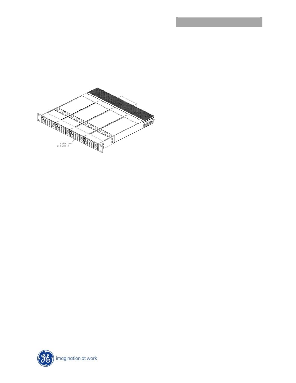
ACE184 Series Power Shelf
Main Output: 600A; Standby output: 8A
Applications
12Vdc distributed power architectures
Mid-End Servers
Blade Servers
Network Equipment
Network Attached Storage
Storage Area Networks
Preliminary Data Sheet
Features
Fits in a 19” wide rack system
Designed for ETS300 rack mounting.
Supported by a retracted side ‘runner’
1U high
Accommodates hot swap capability
Accepts up to 4 modules
Proved in with the CAR1812 and CAR1612
rectifiers
Active current sharing
Hot insertion/removal (hot plug)
UL, CSA and VDE certified
EMI: class A FCC docket 20780 part 15, EN55022
System meets EN6100 immunity and transient
standards
Shock & vibration: IPC-9592A, Class II
Routers/Switches
Enterprise Networks
Advanced workstations
Description
The ACE184 series of Power Shelves are designed for the Datacom and Server market segments. These shelves are
designed to minimize installation and maintenance time with easy access warm-swap insertion, accommodating, up
to 4 modules, rectifiers or converters, with output voltages as high as 60Vdc, in a 19” wide enclosure compliant to
ETS300 rack mounting standards. All the necessary interfacing for output and signaling needs are provided. The
signaling pins of each module are separately brought out for maximum flexibility.
October 29, 2012 ©2012 General Electric Company. All rights reserved.
Page 2
GE Energy
Preliminary Data Sheet
ACE184 Series Power Shelf
Main Output: 600A; Standby output: 8A
Absolute Maximum Ratings
Stresses in excess of the absolute maximum ratings can cause permanent damage to the device. These are absolute stress ratings
only, functional operation of the device is not implied at these or any other conditions in excess of those given in the operations
sections of the data sheet. Exposure to absolute maximum ratings for extended periods can adversely affect the device reliability.
Parameter Device Symbol Min Max Unit
Operating Ambient Temperature All TA -10 70 °C
Storage Temperature All Tstg -40 85 °C
Electrical Specifications
Unless otherwise indicated, specifications apply over all operating input voltage, resistive load, and temperature conditions.
Parameter Device Symbol Min Typ Max Unit
OUTPUT
Main output All I
Standby Output All I
Isolation1 Output - Ground All 500 Vdc
out
0 8 A
out
0 600 A
dc
dc
Port Phenomena test criteria Reference standard
Enclosure ESD (immunity) 8 kVair 4 kVcontact A EN 61000-4-2
1
Isolation in the context of this data sheet documents the capability of the shelf. Actual isolation capability may be further reduced by the isolation
capability of the utilized modules. Consult the module data sheet for actual capability.
October 29, 2012
©2012 General Electric Company. All rights reserved. Page 2
Page 3

GE Energy
ACE184 Series Power Shelf
Main Output: 600A; Standby output: 8A
Status and Control
Some features, such as programming of the output voltage,
may be controlled both by hardware and firmware.
Unless otherwise noted, control of the output voltage via the
signal pin (Vprog) is ‘active’ and overrides as long as the
signal voltage is ≤ 3Vdc. A firmware initiated command,
attempting to change the output voltage will be ignored as
long as the signal voltage (Vprog) is ≤ 3Vdc
Details of analog controls are provided in this data sheet
under Signal Definitions. GE Energy will provide separate
application notes for the I2C protocol ( Document
#97FS2855). Contact your local GE Energy sales
representative for details.
Note that most control and capability functions
Signal Definitions
All signals and outputs are referenced to Output return.
These include ‘Vstb return’ and ‘Signal return’.
Input Signals
Note: Refer to the individual rectifier data sheets for
supported features.
Voltage programming (V
signal can vary the output voltage of all modules.
If 12V output CAR1812 or CAR1612 rectifiers are used, the
output can vary ± 10% from 10.8Vdc to 13.2Vdc. The
equation of this signal is:
V
= 10.8 + (V
out
If 2.5 < Vprog < 3, the output is 13.2V. If Vprog is > 3V or left
open the programming signal is ignored and the unit output
is set at the setpoint of 12Vdc.
This signal is paralleled among the power supplies.
Load share (Ishare): This is a single wire analog signal that is
generated and acted upon automatically by power supplies
connected in parallel. The Ishare pins are tied together
among the power supplies in the shelf. No resistors or
capacitors should get connected to this pin.
Remote ON/OFF: Controls the presence of the main output
voltage. This is an open collector, TTL level control signal.
This signal needs to be pulled HI externally through a
resistor. Maximum collector voltage is 12Vdc and the
maximum sink current is 1mA. A Logic 1 (TTL HI level) turns
ON the main output, while a Logic 0 (TTL LO level) turns OFF
the main output.
This signal is not overwritten by the firmware ON/OFF
instruction. The default firmware setting is ON. An OFF
command either through this signal or firmware would turn
OFF the power supply.
The default state re-initializes if bias power is interrupted to
the processor.
These signals are brought out independently for each power
supply.
* 0.96) 0 < V
prog
): An analog voltage on this
prog
< 2.5
prog
Preliminary Data Sheet
Enable (ON/OFF): This is a short signal pin that controls the
presence of the main output. This pin should be connected
to ‘output return’ on the system side of the output
connector. The purpose of this pin is to ensure that the
output turns ON after engagement of the power blades and
turns OFF prior to disengagement of the power blades.
These signals are brought out independently for each power
supply.
Write protect (WP): This signal protects the contents of the
EEPROM from accidental over writing. When left open the
EEPROM is write protected. A LO (TTL compatible) permits
writing to the EEPROM. This signal is pulled HI internally by
the power supply. Note: only for factory programming.
This signal is interconnected among the power supplies
Output signals
Output current monitor (Imon): A voltage level proportional
to the delivered output current is present on this pin. The
signal level is 150A = 3V when the CAR182 or CAR1612
rectifiers are used.
These signals are brought out independently for each power
supply.
INPUT OK: A TTL compatible status signal representing
whether the input voltage is within the anticipated range.
This signal needs to be pulled HI externally through a
resistor.
These signals are brought out independently for each power
supply.
DC OK: A TTL compatible status signal representing
whether the output voltage is present. This signal needs to
be pulled HI externally through a resistor.
These signals are brought out independently for each power
supply.
Over temp warning: A TTL compatible status signal
representing whether an over temperature exists. This signal
needs to be pulled HI externally through a resistor.
These signals are brought out independently for each power
supply.
If an over temperature should occur, this signal would pull
LO for approximately 10 seconds prior to shutting down the
power supply. The unit would restart if internal temperatures
recover within normal operational levels. At that time the
signal reverts back to its open collector (HI) state.
Fault: A TTL compatible status signal representing whether
a Fault occurred. This signal needs to be pulled HI externally
through a resistor.
These signals are brought out independently for each power
supply.
This signal activates for OTP, OVP, OCP, AC fault or No
output.
Module Present: This pin is connected to ‘output return’
within the power supply. Its intent is to indicate to the
system that a power supply is present. This signal may need
to be pulled HI externally through a resistor.
October 29, 2012 ©2012 General Electric Company. All rights reserved. Page 3
Page 4

GE Energy
ACE184 Series Power Shelf
Main Output: 600A; Standby output: 8A
These signals are brought out independently for each power
supply.
Interrupt (SMBAlert): A TTL compatible status signal,
representing the SMBusAlert# feature of the PMBus
compatible i
needs to be pulled HI externally through a resistor.
Maximum sink current ≤ 4mA and the pull up resistor should
be tied to 3.3Vdc. Open collector (HI) on this signal indicates
that no Interrupt has been triggered.
This signal is paralleled among the power supplies.
Serial Bus Communications
The I²C interface facilitates the monitoring and control of
various operating parameters within the unit and transmits
these on demand over an industry standard I²C Serial bus.
All signals are referenced to ‘Signal Return’.
Device addressing: The microcontroller (MCU) and the
EEPROM have the following addresses:
Device Address Address Bit Assignments
MCU 0xBx 1 0 1 1 A2 A1 A0 R/W
EEPROM 0xAx 1 0 1 0 A2 A1 A0 R/W
Address lines (A1, A0): These signal pins allow up to four (4)
modules to be addressed on a single I²C bus. The pins are
configured automatically in the shelf. Rectifier addressing
increments from left to right as viewed from the front.
Address line (A2): This bit sets the address of the shelf. The
bit setting depends on the rear accessible dip switch and pin
51 of the signal connector. In order to set the address HI
(‘1’), the dip switch needs to be set to Mark 1 and the signal
pin needs to be left open. Setting the dip switch to Mark 0 or
grounding pin 51 will configure the shelf to address bit 0
(LO).
Serial Clock (SCL): The clock pulses on this line are generated
by the host that initiates communications across the I²C
Serial bus. This signal is pulled up internally to 3.3V [ 5V
a 10kΩ resistor. The end user should add additional pull up
resistance as necessary to ensure that rise and fall time
timing and the maximum sink current is in compliance to
the I²C specifications.
This signal is paralleled among the power supplies.
Serial Data (SDA): This line is a bi-directional data line. . This
signal is pulled up internally to 3.3V [ 5V ] by a 10kΩ resistor.
The end user should add additional pull up resistance as
necessary to ensure that rise and fall time timing and the
maximum sink current is in compliance to the I²C
specifications.
This signal is paralleled among the power supplies.
2
C protocol in the power supply. This signal
(Most to Least Significant)
2
] by
Preliminary Data Sheet
Another separate EEPROM IC will provide another 128 bytes
of memory with write protect feature. Minimum information
to be included in this separate EEPROM: model number,
revision, date code, serial number etc.
See the communications protocol for further information.
Communications Protocol
The I²C protocol is described in detail by the I2C and PMBus
Serial Communications Protocol for the CAR Family of
Power Supplies application note.( Document # 97FS2855)
EEPROM
The microcontroller has 96 bytes of EEPROM memory
available for the system host.
2
Module configured with 5V standby output
October 29, 2012
©2012 General Electric Company. All rights reserved. Page 4
Page 5

GE Energy
ACE184 Series Power Shelf
Main Output: 600A; Standby output: 8A
Outline Drawing
Preliminary Data Sheet
Perforated areas need to be
exposed for cooling purposes
Dip switch for Shelf Address:
Mark 0 – ‘A2 pin set to 0’
Mark 1 – ‘A2 pin set to 1’
(if Pin51 is not grounded)
Output Power Terminations
The outputs of the four power supplies are internally connected in parallel and brought out on the rear panel via four sets of
M6 studs with 5/8 inch center spacing, accommodati ng industry standard lugs. The lug terminations can e xit the sh e lf either
above or below the shelf, or to the rear when right angle lugs are utilized. An insulation cover is provided over the lug
terminations and it ca n be rotated to accommodate the cables exiting either upward or downward.
The maximum output current capacity of the lug/wire combination should be sized to carry 300 amperes per set when two
lugs are utilized.
October 29, 2012 ©2012 General Electric Company. All rights reserved. Page 5
Page 6

53
54
55
56
57
58
59
60
GE Energy
Preliminary Data Sheet
ACE184 Series Power Shelf
Main Output: 600A; Standby output: 8A
Connector Pin Assignments
Signal Connector: shelf end: Tyco AMP P/N 1-5499786-1
Mate: Tyco AMP P/N 1-1658621-1
Pin
1
2
3
4
5
6
7
8
9
10
11
12
13
14
15
16
17
18
19
20
Ordering Information
Please contact your GE Energy Sales Representative for pricing, availability and optional features.
Signal Function Pin Signal Function Pin Signal Function
INPUT OK 1
DC OK 1
Mod present 1
Temp OK 1
On / Off 1
Imon 1
N.C.
Fault 1
INPUT OK 2
DC OK 2
Mod present 2
Temp OK 2
On / Off 2
Imon 2
N.C.
Fault 2
INPUTOK 3
DC OK 3
Mod present 3
Temp OK 3
PRODUCT DESCRIPTION PART NUMBER
600A Shelf Power Shelf capable of delivering 600A of main output and 8A of Standby power ACE184RUW12XZ01A
INPUT OK 1
DC OK 1
Module present 1
Temp OK 1 24
Remote On / Off 1 25
Current readout 1 26
27
Fault 1
INPUT OK 2
DC OK 2 30
Module present 2 31
OK 2
Temp
Remote On / Off 2
Current readout 2 34
35
Fault 2
INPUT OK 3
DC OK 3
Module present 3 39
Temp OK 3 40
21
22
23
28
29
32
33
36
37
38
On / Off 3
Imon 3
N.C.
Fault 3
INPUT OK 4
DC OK 4
Mod present 4
Temp OK 4
On / Off 4
Imon 4
N.C.
Fault 4
N.C.
N.C.
N.C.
N.C.
N.C.
N.C.
N.C.
N.C.
Remote On / Off 3
Current readout 3
Fault 3 44
INPUT OK 4 45
DC OK 4 46
Module present 4 47
Temp OK 4
Remote On / Off 4
Current readout 4 50
51
Fault 4
41
42
43
48
49
52
N.C.
I_share
V_prog Voltage Setting
INT
SCL
SDA
WP
RS +
RS -
RTN
Shelf Address
Vsb
Vsb
Vsb
Vsb
N.C.
Vsb_rtn
Vsb_rtn
Vsb_rtn
Vsb_rtn
Current sharing
I²C interrupt
I²C clock line
I²C data line
Write Protect
Positive sense
Negative sense
Signal return
A2 pin
output
standby
output
standby
output
standby
output
standby
standby return
standby return
standby return
return
standby
Contact Us
For more information, call us at
USA/Canada:
+1 888 546 3243, or +1 972 244 9288
Asia-Pacific:
+86.021.54279977*808
Europe, Middle-East and Africa:
+49.89.878067-280
India:
+91.80.28411633
October 29, 2012 ©2012 General Electric Company. All rights reserved. Page 6
www.ge.com/powerelectronics
 Loading...