

Page 1

6KCV301PDP33
INSTRUCTIONS
GE Industrial Control SystemsGE Industrial Control Systems
Profibus - DP Bus for AV300i
TM
Page 2

These instructions do not purport to cover all details or variations in equipment, nor to
provide every possible contingency to be met during installation, operation, and
maintenance. If further information is desired or if particular problems arise that are
not covered sufficiently for the purchaser’s purpose, the matter should be referred to
GE Industrial Control Systems.
This document contains proprietary information of General Electric Company, USA
and is furnished to its customer solely to assist that customer in the installation,
testing, operation, and/or maintenance of the equipment described. This document
shall not be reproduced in whole or in part nor shall its contents be disclosed to any
third party without the written approval of GE Industrial Control Systems.
© 1999 by General Electric Company, USA. All rights reserved.
Page 3

Profibus-DP
TABLE OF CONTENTS
1.0 INTRODUCTION ................................................................ 5
1.1 ABOUT THIS MANUAL ........................................................................ 5
1.2 OVERVIEW OF PROFIBUS-DP .............................................................. 5
2.0 HARDWARE DESCRIPTION .............................................. 7
2.1 DIMENSIONS, WEIGHT, DEGREE OF PROTECTION ................................ 7
2.2 MOUNTING .......................................................................................... 8
2.3 POWER SUPPLY.................................................................................. 9
2.4 LEDS ................................................................................................... 9
2.5 TECHNICAL SPECIFICATION .............................................................. 10
2.6 INTERFACE. ....................................................................................... 10
3.0 BYTES ASSIGNMENT FOR DATA EXCHANGE ............... 13
3.1 CONTROL BYTE SETTING ................................................................... 15
3.2 MEANING OF HANDSHAKE ............................................................... 16
3.3 EXAMPLE OF DRIVE PARAMETER ACCESS ....................................... 17
3.3.1 Drive parameter writing ................................................... 17
3.3.2 Drive parameter reading .................................................. 18
4.0 PROCESS DATA CHANNEL CONTROL ............................. 19
5.0 ALARMS .......................................................................... 23
5.1 PROFIBUS-DP ALARMS .................................................................... 23
5.2 DRIVE ALARMS HANDLING ............................................................... 23
6.0 VIRTUAL DIGITAL INPUT/OUTPUT CONTROL ................ 25
7.0 KEYBOARD INTERFACE.................................................. 27
7.1 MAIN MENU STRUCTURE ................................................................. 27
7.1.2 Warning and error message handling ............................... 27
7.2 6KCV301PDP33 INFO MENU .............................................................. 28
8.0 IDENTIFICATION CODES ................................................ 29
8.1 CARD IDENTIFICATION NUMBER ....................................................... 29
8.2 CARD CONFIGURATION CODES.......................................................... 29
8.3 DATA TYPE AND GSD FILE DISKETTE ................................................. 29
——————
TABLE OF CONTENTS ——————
III
Page 4

GEI-100422
9. MISCELLANEOUS .............................................................. 31
9.1 GLOSSARY ........................................................................................ 31
9.2 ABBREVIATIONS ............................................................................... 31
9.3. REFERENCES .................................................................................... 31
IV
—————— TABLE OF CONTENTS ——————
Page 5

Profibus-DP
1.0 INTRODUCTION
This manual describes the 6KCV301PDP33 optional card for connecting of
inverters to Profibus-DP networks.
Drives belonging to AV300i series can be connected in network through the
6KCV301PDP33 card.
This manual is intended for design engineeres and technicians responsible for
the maintenance, commissioning and operation of Profibus-DP systems. A
basic knowledge of Profibus-DP is assumed and may be found in the “Draft
Standard DIN 19245 Part 3” manual.
1.1 ABOUT THIS MANUAL
Chapter 2 Mechanical Card mounting, electrical connections
and switches setting
Chapter 3 Master - Slave transmission data
Chapter 4 Assignment of the drive parameter to the Process
Data Channel
Chapter 5 Profibus-DP diagnostic handling
Chapter 6 Assignment of the drive parameter to the virtual
digital I/O
Chapter 7 Keypad drive menu
Chapter 8 Identification number and codes for Bus connection
Chapter 9 Miscellaneous: glossary, abbreviations and
references
1.2 OVERVIEW OF PROFIBUS-DP
Profibus-DP is a field Bus designed for a fast data exchange relating to sensors
/ actuators level; the communication is established between a Master central
unit (PLC or PC) and Slave units, i.e. sensors, actuators, drives, etc.
The data exchange is cyclic; the Master unit reads the Slaves input data and
writes the Slaves output data. The Bus cycle time is shorter than the cycle time
of the central unit; the Baud Rates for the 6KCV301PDP33 card are from 9,6
kbit/s to 12 kbit/s according to Profibus-DP standard part. 3.
5—————— INTRODUCTION ——————
1
Page 6

GEI-100422
The total cycle time depends on the number of Slaves connected; the 1.5-Mbit/
s Baud Rate allows 8 SIEI drives to be polled in 6 milliseconds.
The physical support is the RS485 serial line; the max. number of Slaves
connected to the Bus is 125.
Example of Mono-Master Profibus-DP system.
MASTER
SLAVESLAVE SLAVE
Profibus-DP allows a Multi-Master system as well. For further information
please refer to chapters 6 and 7 of the “Draft Standard DIN 19245 Part 3”
manual.
1
6
—————— INTRODUCTION ——————
Page 7
Profibus-DP
2.0 HARDWARE DESCRIPTION
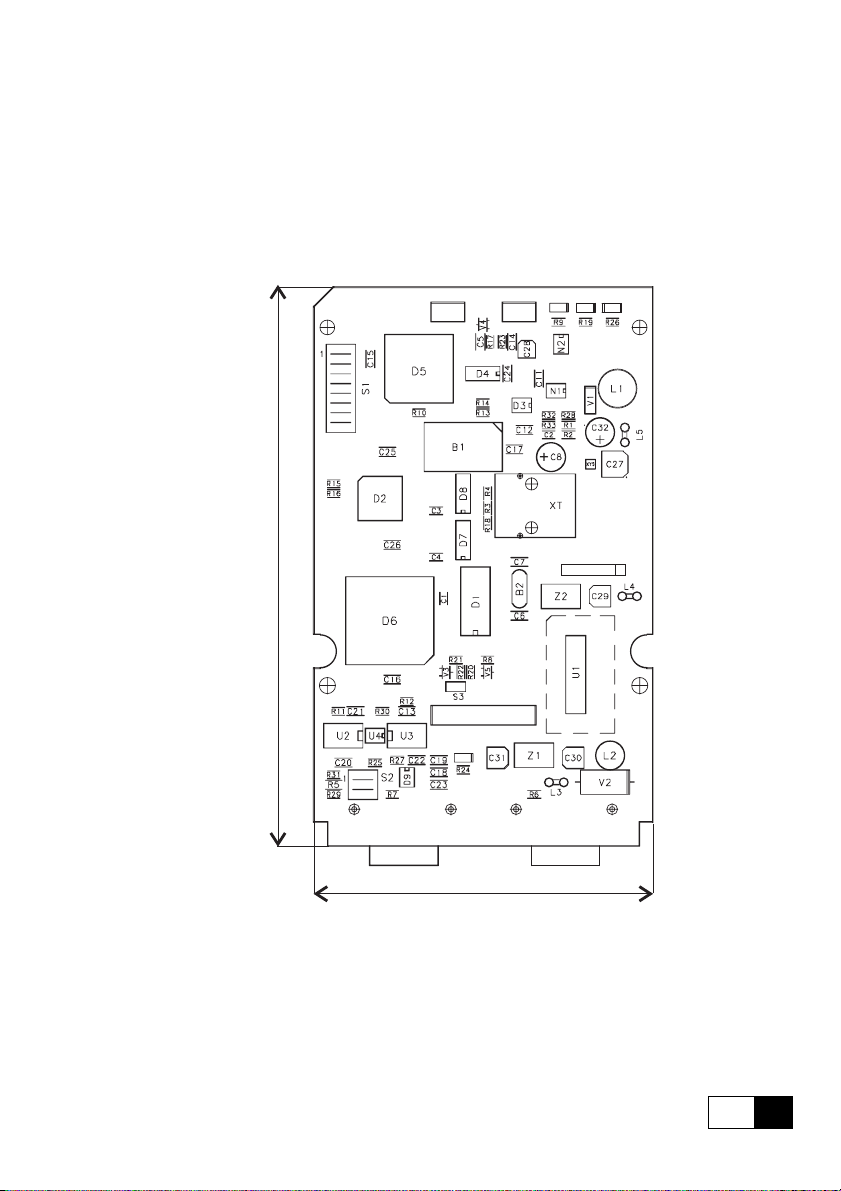
2.1 DIMENSIONS, WEIGHT, DEGREE OF PROTECTION
+5V RST DEA
H
+5VE
XS1 XS2
L
SBI-PDP-33
Dimensions H=145 mm [5.7 “], L = 88 [3.4 “] , D = 27.5 [1 “]
W eight 102 g [3.57 oz]
Degree of protection IP00
2
7—————— HARDW ARE DESCRIPTION ——————
Page 8
GEI-100422
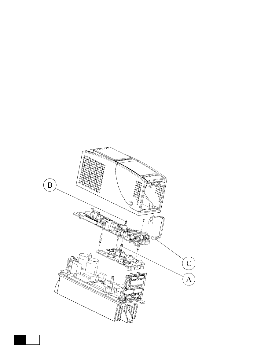
2.2 MOUNTING
The 6KCV301PDP33 card is supplied with standoffs, screws, washers and a
6KCV301PDP33-Drive link cable provided with connectors.
1 . Switch the drive off.
2. If the card is inside the drive mounted (see example below), fasten the
6KCV301PDP33 card to the drive regulation board by means of screws
(B) and standoffs (A). The 6KCV301PDP33-Drive link cable (C) must be
connected between XT1 (on Regulation board) and XT (on
6KCV301PDP33 card).
If the card is mounted outside the drive, the 6KCV301PDP33 card has to
be fastened to a DIN rail by using the external mounting kit; it is
recommended to keep the 6KCV301PDP33 card as close as possible to the
drive. Do not put the 6KCV301PDP33-Drive link cable near power cables.
2
8
—————— HARDW ARE DESCRIPTION ——————
Page 9

Profibus-DP
3 . The 6KCV301PDP33-Drive link cable is connected to the XT connector
on the 6KCV301PDP33-card.
4. The bus terminating resistors are connected or disconnected through the
S2 dip switch.
The last physical card in network shall have such resistors connected in
case the connector in use should not contain terminating resistors itself.
ON = connected
OFF = disconnected.
5 . The S1 dip switch determines the Slave address.
The addresses “0” and “1” are reserved to the Master and can not be
used. The switch S1-8 is not significant for the address and must always
be set to OFF . The address is only detected when the card is switched on.
If the address has been modified, the Profibus-DP interface card has first
to be switched off and then on in order assume the new address.
6 . Connect the Bus cable to XS1 or XS2 connectors.
7 . Switch on the drive.
8. The LEDs +5V and +5VE light up.
9. The LED DEA lights up when the communication enters in the Data
Exchange Phase.
2.3 POWER SUPPLY
The power supply is provided by the XT connector which is also used to
transfer data between the 6KCV301PDP33 card and the drive regulation card.
Current draw: 350 mA
2.4 LEDS
+5V +5V power supply.
RST Reset active.
DEA Data Exchange Phase active.
+5VE +5V power supply on the RS 485 driver side galvanic isolated.
9—————— HARDW ARE DESCRIPTION ——————
2
Page 10
GEI-100422
2.5 TECHNICAL SPECIFICATION
Storage temperature: -20°... +70°C (-68...+158°F)
Operating temperature: 0°... +55°C (32...+131°F)
These temperatures are adequate to those of the drive, to which the cards are
connected.
2.6 INTERFACE.
For the mechanical connection, according to the internal or external mounting,
please use the kit and the mounting instruction sheet supplied with the card.
For the electrical connection please use the 6KCV301PDP33-Drive link cable,
also supplied.
For the connection to the Bus please use a shielded twisted cable recommended
by Profibus specification.
The pinout of the Bus connectors are the following:
N.C.
+5V
100 ohm to 0V
N.C.
RX/TX-B
RX/TX-A
N.C.
N.C.
0V
6
7
8
9
1
2
3
4
5
(XS1 - XS2)
The connection among the single cards is implemented by a shielded cable as
shown in the following diagrams:
2
10
—————— HARDW ARE DESCRIPTION ——————
Page 11

Profibus-DP
6KCV301PDP33
XS1
XS2
XS1
XS2
XS1
XS2
PE
Shield
6KCV301PDP33 6KCV301PDP33
6KCV301PDP33 6KCV301PDP33
Vcc
390 ohm150 ohm
S2-2
A
XS1/XS2
XS1/XS2 S2-2
A
Vcc
390 ohm150 ohm
Gnd
390 ohm
S2-1
S2-1
B
B
390 ohm
Gnd
2
11—————— HARDW ARE DESCRIPTION ——————
Page 12

Page 13

Profibus-DP
3.0 BYTES ASSIGNMENT FOR DATA EXCHANGE
The 6KCV301PDP33 card uses a 16-byte frame. The first 8 bytes represent the
configuration channel for the acyclic data exchange, the other 8 are the process
data channel for the cyclic exchange.
The bytes assignment is as follows:
Configuration channel Process data channel
01234567
WORD 0 WORD 1 WORD 2 WORD 3
Data / error
Subindex / Type
Index
Control byte
As to the Data/Error and Index fields, the data format is arranged from the
least to the most significant byte. The meaning of the fields is the following:
A ) Data frame from Master to Slave:
1 ) Data / Error
The content of this field depends on the kind of service carried out: in
case of writing it contains the parameter value, in case of reading it has no
meaning.
2 ) Subindex/Type
It contains the parameter subindex, if any. If the parameter has no
subindexes it has to be set to 0. For parameters with subindex, this has to
be set from 1 to the max. number of parameter elements; the value 0 is not
accepted and rejected. It is not possible to read the whole object, but only
its single elements. In case of service carried out towards the DGF option,
this field should contain the data type (see DGF manual).
3 ) Index
Index of the parameter involved in the operation with format low byte high byte.
4 ) Control byte
The meaning of this byte is described in 3.1.
3
13—————— BYTE ASSIGNMENT ——————
Page 14

GEI-100422
B ) Data frame from Slave to Master:
1 ) Data / Error
The content of this field depends on the kind of service carried out. In
case of writing it contains the operation result. In case of reading it contains
the parameter value if the reading had positive result; if not, it contains the
detailed error code. As to the error codes and operation result, please
refer to drive manual).
2 ) Subindex/Type
It contains the parameter subindex, if any. If the parameter has no
subindexes it has to be set to 0. For parameters with subindex, this must
be set from 1 to the max. number of parameter elements; the value 0 is not
accepted and rejected. It is not possible to read the whole object, but only
its single elements. In case of service carried out towards the DGF option,
this field contains the data type (see DGF manual).
3 ) Index
Index of the parameter involved in the operation with format low byte high byte.
4 ) Control byte
The meaning of this byte is described in 3.1.
In case of service towards DGF option, please refer to the DGF manual for
error codes.
3
14
—————— BYTE ASSIGNMENT ——————
Page 15

3.1 CONTROL BYTE SETTING
76543210
Profibus-DP
Service
210
000No request communications
0 0 1 Drive parameter reading
0 1 0 Drive parameter writing
1 1 0 DGF option parameter reading
1 1 1 DGF option parameter writing
Reserved
Handshake
Status
Bit
7
0 Service carried out without errors
1 Error occurred
Bit
Meaning
Meaning
The status bit is only used by the Slave, therefore it has a meaning only during
the transmission from Slave to Master; in the transmisson from Master to Slave it has always to be set to 0.
15—————— BYTE ASSIGNMENT ——————
3
Page 16

GEI-100422
3.2 MEANING OF HANDSHAKE
The Handshake bit prevents the same service request from being carried out
more than once and its function is the same both in the direction from Master
to Slave and from Slave to Master. The explanation below refers to the direction
Master to Slave, but the same considerations may be applied for the opposite
direction.
The default value of this Bit is 0. Every time that a transition of this Bit occurs,
both from 0 to 1 (positive edge) and from 1 to 0 (negative edge), the Slave
carries out the service requested by the Master through the data frame previously
set. Therefore, this Bit acts as a Trigger, through which the Master indicates
the Slave that the data for the requested service are ready.
The Slave responds to the Master in the same way , by causing a Handshake Bit
transition (both positive or negative).
Consequently, the Master is able to send a service on the Bus only if its
Handshake Bit is equal to the one received by the Slave.
During the initialization and in case the Master does not receive the Slave
response within a Timeout of 500 mSec, the Master shall send a no-request
service (all Bits are set to 0), thus allowing the Slave to perform a
communication Reset. This causes the reset of the Slave Handshake Bit.
The Timeout for the service towards the DGF option shall be longer (1.5 sec).
The Master should therefore have two different Timeouts: one for the services
towards the drive and one for those towards the DGF option.
3
16
—————— BYTE ASSIGNMENT ——————
Page 17

Profibus-DP
42h 2Ch 20h 00h E8h 03h 00h
Drive parameter value to be
written
Drive parameter index
Control Byte (see section 3.1)
Drive parameter subindex must
always be set to zero
00h
3.3 EXAMPLE OF DRIVE PARAMETER ACCESS
These example are referred to the AV300i drive software version 1.X. It is
assumed that the handshake bit is set to 0 at the beginning.
For error codes from the drives please refer to the drive manuals.
3.3.1 Drive parameter writing
The Ramp Ref 1 parameter of the A V300i drive (software version 1.X) must be
written by the master. The required numerical information is :
1 ) Ramp ref 1 parameter index of the AV300i drive : 202Ch (8192 + 44).
2 ) Value to be written: 1000dec (03E8h).
Response from the slave:
42h 2Ch 20h 00h 00h 00h XX
XX
No meaning
Response code of the drive
parameter access (please refer
to the drive manual)
Drive parameter subindex
Drive parameter index
Control Byte (see section 3.1)
3
17—————— BYTE ASSIGNMENT ——————
Page 18

GEI-100422
3.3.2 Drive parameter reading
The Actual speed parameter of the A V300i drive (software version 1.X) must
be read by the master. The required numerical information is :
1 ) Actual speed parameter index of the A V300i drive : 207Ah (8192 + 122).
2 ) Value to be read is 1500dec (05DCh)
41h
7Ah 20h 00h XX
Response from the slave:
XX XX XX
No Meaning
Drive parameter subindex must always
be set to zero
Drive parameter index
Control Byte (see section 3.1)
41h 7Ah 20h 00h DCh05h 00h
3
18
—————— BYTE ASSIGNMENT ——————
00h
Read value of the drive parameter
Drive parameter subindex
Drive parameter index
Control Byte (see section 3.1)
Page 19

Profibus-DP
4.0 PROCESS DATA CHANNEL CONTROL
This function allows the assignment of the drive parameter to the Process Data
Channel W ords.
The 6KCV301PDP33 card uses four words (WORD) for the Process Data
Channel (abbr. PDC Process Data Channel ).
The Process Data Channel for the 6KCV301PDP33 card has the following
configuration
WORD 0 WORD 1 WORD 2 WORD 3
The Slave can both read and write Process Data Channel data.
The data read from Profibus-DP by the Slave are referred to as input data; the
data written in Profibus-DP by the Slave are referred to as output data.
The Slave parameters are cyclically read by the Master by assigning drive
parameters to the PDC output configuration parameters.
The Master cyclically transmits drive parameters to the Slave by assigning
drive parameters to the PDC input configuration parameters.
Drive
6KCV301PDP33
Input
PDC
Output
————— PROCESS DATA CHANNEL CONTROL ———
19
4
Page 20

Operating modes:
Process data from Profibus-DP
GEI-100422
012
0123
WORD 0 WORD 1 WORD 2 WORD 3
PAR. 1 PAR. 2 PAR. 3
DRIVE PARAMETER
PAR. 1 PAR. 2 PAR. 3 PAR. 4
WORD 0 WORD 1 WORD 2 WORD 3
0123
0123
Process data to Profibus-DP
3
PAR. 4
PDC Input channel
PDC Input memory
PDC Input
configuration parameter
PDC Output
configuration parameter
PDC Output memory
PDC Output channel
sb3_4020
The drive parameters assignment to the Process Data Channel W ords is carried
out by means of the index of the parameter itself.
Only drive parameters with a 16-Bit width (1 Word) may be assigned to the
Process Data Channel.
4
20
————— PROCESS DAT A CHANNEL CONTROL ———
Page 21

Profibus-DP
Input data descriptor of the Process Data Channel:
PDC Input configuration
202Ah
8234 dec
00
st
1 Word PDC
WORD 0 WORD 2
Speed ref 1 Ramp ref 1
[42] dec 2Ah [44] dec 2Ch
NOTE:
Example referred to A V300i drives (software version 1.X).
Parameters with index 0000 mean that the Word is not
assigned to any drive parameter.
0000
00
202 Ch
8236 dec
00
0000
00
nd
2 Word PDC
rd
3 Word PDC
th
4 Word PDC
For PDC configuration, please refer to the “OPTION 1” chapter of the drive
instruction manual.
————— PROCESS DATA CHANNEL CONTROL ———
21
4
Page 22

Page 23

Profibus-DP
5.0 ALARMS
5.1 PROFIBUS-DP ALARMS
The alarms indicated to the drive by the 6KCV301PDP33 card are the following:
1 - Bus loss: if an accidental interruption of the connection occurs, this alarm
is generated.
2 - 6KCV301PDP33 Hardware Fault: if the 6KCV301PDP33 card is faulted,
this alarm is generated.
The alarm handling carried out by the drive depends on the drive itself and
how the alarms are configured.
If the Master is switched off before the Slave, the Bus-Loss alarm occurs; the
drive handles this event by not storing the alarm in order to avoid having the
alarm annunciated when the drive is next switched on.
The communication between Master and Slave can only be carried out if the
initialization of the drive and of the 6KCV301PDP33 card is successfully
terminated; if not, it is not possible to determine the cause of the erroneous
initialization using the Bus.
5.2 DRIVE ALARMS HANDLING
The drive reports automatically its status to the 6KCV301PDP33 card, if an
alarm condition occurs.
When the communication is established, the drive status is sent to the Master
in at the moment in which the drive initialization has terminated.
Every time the Drive changes its status, the 6KCV301PDP33 card sends the
updated drive status to the Master by means of a diagnostic message ( please
refer to “Draft Standard DIN 19245 Part 3” sect. 8.3.1 ).
The information are contained in the ‘User Specific Diagnostic Data’ field of
the diagnostic message.
This field is made up of three Bytes. The first contains the ‘User Specific
Diagnostic Data Length (in bytes)’ and is set to three. The second and the third
contains the code of the drive status (for the code please refer to the drive
manual). When a drive alarm occurs, also the ‘Ext_Diag’ bit in the first Byte
of the ‘Diagnostic Data’ is set to 1.
23—————— ALARMS ——————
5
Page 24

Page 25

Profibus-DP
6.0 VIRTUAL DIGITAL INPUT/OUTPUT CONTROL
Virtual digital I/O are descrete signals which can be controlled by the master:
- 16 Input and 16 Output are available with the 6KCV301PDP33 board.
Virtual Dig I/O are thus an additional terminal strip:
PDC In Dig in
0
Enable
1
Start/stop
0
1
2
3
2
Jog+
3
Jog -
4
5
6
7
8
9
10
11
12
13
14
15
16
As for the digital terminals, before operating the virtual digital I/O, drive
parameters must be assigned to the single terminal; in order to do this, please
refer to the drive manual.
Digital I/O value can be cyclically and fast transferred through the PDC channel,
in order to do this, the virtual digit I/O value parameter must be assigned to
one of the PDC words.
Above picture shows that the virtual digital input has been assigned to the
PDC Input Word 0. The example reports also some drive signal assigned to
the virtual digital input.
For virtual digital I/O configuration, please refer to the “OPTION 1” chapter
of the drive instruction manual.
25———— VIR TUAL DIGIT INPUT OUTPUT CONTROL ———
6
Page 26

Page 27

Profibus-DP
7.0 KEYBOARD INTERFACE
7.1 MAIN MENU STRUCTURE
This structure appears when the Enter key is pressed and “OPTION1” is
displayed; in this case, keypad control passes to the 6KCV301PDP33 card.
OPTION 1
SBI INFO
SB3_8000
Move between the Menus by pressing the Cursor-Up/Cursor-Down keys and
use the Enter key to enter the currently displayed Menu. Pressing the Cancel
key in any displayed menu causes the “OPTION1” Menu to appear and keypad
control returns to the Drive.
7.1.2 Warning and error message handling
W arning and error messages can be displayed on the first and second rows of
the keypad’s display; a maximum of 16 characters can be displayed per line.
The Cancel key must be pressed in order to clear these messages, at this point
the system automatically returns to the immediately superior Menu level.
7
27—————— KEYBOARD INTERFACE ——————
Page 28

GEI-100422
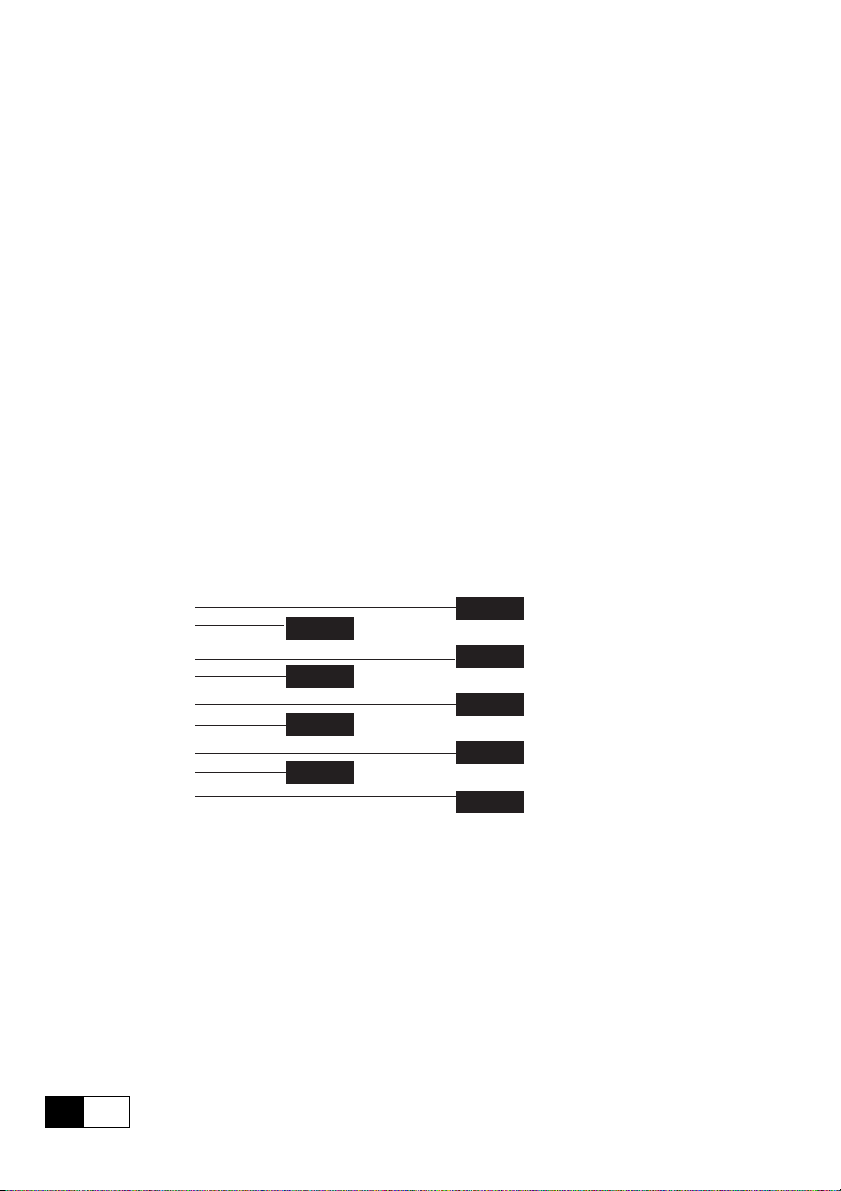
7.2 6KCV301PDP33 INFO Menu
This Menu is used to display various information about the 6KCV301PDP33
card; all data items are strictly read-only.
SBI INFO
Station Address
XXX
Baud Rate
Baud search
Communic. status
Wait parameter
SYNC = ON/OFF
FREEZE = ON/OFF
SPC3 initialization
OK Failed
Software version
V. X.XXX
Compatib. index
V XX.XX
SB3_8010
Move between the Menu items by pressing the Cursor-Up/Cursor-Down keys;
use the Cancel key to return the immediately superior Menu level.
The”Baud Rate”, Communic. status” and “SYNC=ON/OFF” data items are
automatically refreshed.
7
28
—————— KEYBOARD INTERFACE ——————
Page 29

Profibus-DP
8.0 IDENTIFICATION CODES
8.1 CARD IDENTIFICATION NUMBER
The Profibus-DP protocol requires an identification number for every kind of
devices that can be connected to the Bus.
The identification number assigned to the 6KCV301PDP33 card by the
Profibus Nutzerorganisation is the following:
00F2 hexadecimal corresponding to 242 decimal
TSB8130
8.2 CARD CONFIGURATION CODES
The 6KCV301PDP33 card does not require user parameter data.
The configuration data consist of 2 Bytes made up as follows:
Byte
1 183-B7
2 183-B7
Value
decimal-hexadecimal
Tsb8140
For the meaning of these bytes please refer to the paragraph 8.3.5 of the “Draft
Standard PROFIBUS -DP DIN 19245 Part 3” manual.
8.3 DATA TYPE AND GSD FILE DISKETTE
This diskette contains the type files and GSD files suitable for the Profibus-DP
network configurator.
The files contained in the TYPEFILE directory have to be copied in the work
directory of the configurator.
The file contained in the WINCOM directory has to be copied in the work
directory of the configurator for WINDOWSTM environment.
8
29—————— IDENTIFICATION CODES ——————
Page 30

Page 31

Profibus-DP
9. MISCELLANEOUS
9.1 GLOSSARY
- Master PLC or PC device controlling the Profibus-
DP; it has the right to access the Bus.
- Slave Drive or Input/Output modules without rights
to access the Bus.
- Process Channel Channel for the fast, cyclic and high-priority
data transfer of parameters previously
configured.
- Configuration Channel Channel for the non-cyclic and low-priority
data transfer used, for instance, for the drive
configuration.
9.2 ABBREVIATIONS
- PDC Process Data Channel.
- DP Decentralized Peripherals.
9.3. REFERENCES
1 - Draft Standard PROFIBUS-DP DIN 19245 Part 3.
Issue 1994 by Profibus Nutzeroganisation e. V.
2 - DGF option manual
3 - AV300i drive manual.
31—————— MISCELLANEOUS ——————
9
Page 32

MANUALE 6KCV301PDP33 (2/99)
Rev. 0.0 - 11.2.99
We bring good things to life.
GEI-100422 Rev. 0.0 (2/99)
GE Industrial Control Systems
Internet Address: http://www.ge.com
 Loading...