

Page 1
6KCV301ENC
for AV-300i Drives
Digital Encoder Input Expansion
and Encoder repeater
INSTRUCTIONS
GE Industrial SystemsGE Industrial Systems
Page 2

These instructions do not purport to cover all details or
variations in equipment, nor to provide every possible contingency to be met during installation, operation, and
maintenance. If further information is desired or if particular
problems arise that are not covered sufficiently for the
purchasers purpose, the matter should be referred to GE
Industrial Systems.
This document contains proprietary information of General
Electric Company, USA and is furnished to its customer
solely to assist that customer in the installation, testing,
operation, and/or maintenance of the equipment described.
This document shall not be reproduced in whole or in part
nor shall its contents be disclosed to any third party without
the written approval of GE Industrial Systems.
© 1999 by General Electric Company, USA. All rights
reserved.
Page 3

Table of contents
1. INTRODUCTION ...................................................................... 5
2. MOUNTING ............................................................................. 7
3. ENCODER CONNECTOR ......................................................... 8
3.1 ENCODER INPUT ................................................................................. 8
3.2 ENCODER REPEATER CONNECTOR .................................................... 9
3.2.1 Divider for encoder repeater ........................................................ 10
4. LEDS ...................................................................................... 11
5. JUMPERS ............................................................................. 11
6. TECHNICAL DATA ................................................................. 12
Dimensions and weight........................................................................... 12
General data ............................................................................................12
Encoder interface ..................................................................................... 12
Encoder repeater ..................................................................................... 13
Temperature ............................................................................................ 14
7. ACCESSORIES ...................................................................... 14
8. MAXIMUM WIRE SIZES ....................................................... 14
9. EXAMPLE OF APPLICATION................................................. 15
Tach Follower .......................................................................................... 15
Page 4

Page 5

6KCV301ENC
1. INTRODUCTION
The 6KCV301ENC card is an AV300i drive option used to add a second
optocoupled encoder input and an encoder repeater to the drive. It is possible
to use only one I/O expansion card per Drive.
This option card features:
- 1 optocoupled digital encoder input
- A / A not +5V or 15V/24V selectable (150kHz max)
- B / B not +5V or 15V/24V selectable (150kHz max)
- C / C not +5V or 15V/24V selectable (150kHz max)
- Encoder qualifier input (QC+ / QC -) 15VDC up to 24VDC
Encoder loss detection is available only when a differential encoder is used
with a 15V – 24VDC power supply
- 1 optocoupled encoder data repeater TTL (@5V) and HTL (@15….24V)
- A / A not +5V and 15V/24V (150kHz max)
- B / B not +5V and 15V/24V (150kHz max)
- C / C not +5V and 15V/24V (150kHz max)
- Encoder qualifier (home position signal) input (QC+ / QC not) 15VDC
up to 24VDC
Encoder repeater has frequency divider functionality selectable between 1,
2, 4, 8 times using hardware jumpers.
Digital Encoder Input Expansion and Encoder Repeater
5
Page 6

GEI-100428
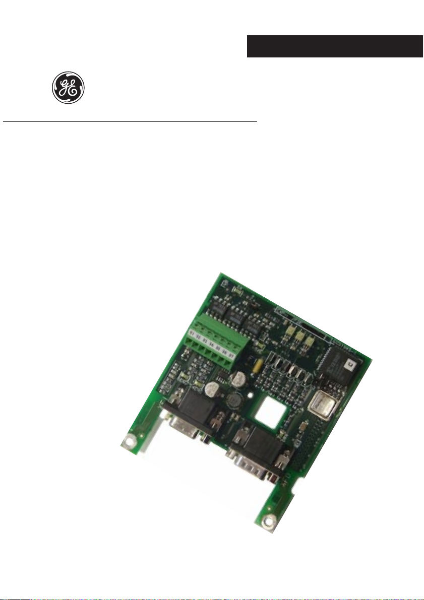
Front side
Back side
Digital Encoder Input Expansion and Encoder Repeater
6
Page 7

6KCV301ENC
2. MOUNTING
The 6KCV301ENC card is supplied with standoffs and the cable for
connection between regulation and expansion card .
1. Switch the drive off.
2. Fasten the 6KCV301ENC card to the drive regulation board by means
of screws (B) and standoffs (A).
3. The 6KCV301ENC card is connected to the regulator card through the
XH connector using the supplied cable. The power supply (+5V) and the
control signals are provided by the drive via the XH connector.
4. Switch on the drive.
Digital Encoder Input Expansion and Encoder Repeater
7
Page 8

GEI-100428
3. ENCODER CONNECTOR
3.1 ENCODER INPUT
The 6KCV301ENC expansion board is used to add an additional digital
encoder input through a 15 pin high density connector (VGA type). An external
power supply for the encoder type (+5V or +15V/24V) is needed. Terminal
points 93,94,95 are used to connect an external power supply.
ENCODER INPUT
Connector
PIN 12 3 45678
B-
Signal
I/O I O I I I I O I
(5V)
+24VEC+
(5V)C-(5V)A+(5V)A-(5V)
XFI
0VE
B+
(5V)
Connector
PIN 9 10 11 12131415
Signal +5VE
I/O OI IIIII
WARNING!
A+
(15V
up to
24V)
It is not possible a connection of 5V encoder type signals
A-
(15V
up to
24V)
B+
(15V
up to
24V)
XFI
B-
(15V
up to
24V)
C+
(15V
up to
24V)
C(15V
up to
24V)
exp2F10
and 15V/24V encoder type signals contemporary.
ENCODER SUPPLY
Connector
Terminal 91 92 93 94 95
Signal
QC1+ QC1- +5VE +24VE 0VE
XSI
exp2F20
QC+ and QC- is the encoder qualifier (home position signal) input. Encoder
power supply should be connected to +5VE and 0VE (for +5V encoder) or
+24VE and 0VE (for +15V/+24V encoder).
Digital Encoder Input Expansion and Encoder Repeater
8
Page 9

6KCV301ENC
3.2 ENCODER REPEATER CONNECTOR
The optocoupled encoder repeater interface allows the encoder data repeater
simultaneously with TTL level and HTL level through a 15 pin high density
connector (VGA type). An external power supply (+15V/24V) is needed
through terminals 96,97.. This power supply is also needed for the +5V
repeater.
ENCODER REPEATER
Connector
PIN 12345678
Signal
B-
(TTL)
C+
*
(TTL)C-(TTL)A+(TTL)A-(TTL)
XFO
B+
*
(TTL)
Connector
PIN 9 101112131415
Signal *
* Reserved
A+
(HTL)A-(HTL)B+(HTL)B-(HTL)C+(HTL)C-(HTL)
ENCODER REPEATER SUPPLY
Connector
Terminal 94 95
Signal
+24V DRV 0V DRV
XFO
exp2F30
XSI
exp2F40
TTL driver are self protected against short circuit for 1 sec, after this time
the drivers could be damaged. HTL driver are protected against short circuit
through 375mA fuse Bussman MCR 3/8 type. An external protection is
recommended with external power supply using 500mA fuses at least.
Digital Encoder Input Expansion and Encoder Repeater
9
Page 10

GEI-100428
3.2.1 Divider for encoder repeater
The board has jumpers to set a divider ratio between the encoder repeater
frequency compared to the encoder input data.
The following divider settings are available: /1, /2, /4, /8.
The following table describes the phase shift between input and output.
Divider Description
A out channel is in phase with A in channel
/1
B out channel is in phase with B in channel
C out channel is in phase with C in channel
A out channel edges are phased with either rising or falling edges
of A in (depending on initial condition)
B out channel edges are phased with either falling or rising edges
/2
of A in (depending on initial condition)
C out channel raising edge is in phase with rising edge of C in
and the falling edge after two edges of A in and/or B in
A out channel is in phase with falling edge of A in channel
B out channel is in phase with falling edge of A in channel
/4
C out channel rising edge is in phase with rising edge of C in
and the falling edge after five edges of A in and/or B in
A out channel is in phase with falling edge of A in channel
B out channel is in phase with falling edge of A in channel
/8
C out channel rising edge is in phase with rising edge of C in
and the falling edge after nine edges of A in and/or B in
exp2F50ge
Digital Encoder Input Expansion and Encoder Repeater
10
Page 11

6KCV301ENC
4. LEDs
+5V ________________________ The led is lit when internal +5V power supply is
available from the Drive.
5ENC ______________________The led is lit when +5V power supply is provided by
XSI terminal.
24ENC _____________________ The led is lit when +15÷24V power supply is provided
by XSI terminal.
+5VE _______________________ The led is lit when power supply for driver encoder
repeater TTL (+5V) is provided.
DRV _______________________ The led is lit when power supply for driver encoder
repeater TTL (+15÷24V) is provided.
5. JUMPERS
Name Default
S1 and S2 Setting divider for encoder repeater (see table below) OFF, OFF
ON 0 Channel included in the encoder loss logic
S7 OFF
OFF 0 Channel not included in the encoder loss logic
Description
exp2F70
Set Jumper to ON when encoder loss detection is used also for zero channel.
(Alarm active only if a digital encoder with all A, Anot, B, Bnot channels and
+15V/24V power supply is used)
DIVIDER FOR ENCODER REPEATER SELECTION
Encoder divider Jumper S1 Jumper S2
/1 OFF OFF
/2 OFF ON
/4 ON OFF
/8
Digital Encoder Input Expansion and Encoder Repeater
ON ON
exp2F80
11
Page 12

Dimensions and weight
105.41 mm
GEI-100428
6. TECHNICAL DATA
92.08 mm
Dimensions __________________ 3.6 inches [92.08mm] x 4.1 inches [105.41 mm]
W eight ______________________ 1.5 oz [45 g]
General data
Internal power supply from the drive ______________ +5VDC
Encoder interface
Interface type _______________________________ optocoupled digital encoder
Encoder sw selection__________________________ ENCODER 2
Digital Encoder Input Expansion and Encoder Repeater
12
input interface
Page 13

6KCV301ENC
Standard inputs ______________________________ A+, A-, B+, B-, C+, CAdditional input for encoder qualifier ______________ QC1+,QC1- (optocoupled)
Encoder power supply _________________________ +5V or 15V/24V , selectable
V oltage input range High level (on pin) ) (U
V oltage input range Low level (on pin) ) (U
) ________ 2.5V up to 5.25V (@5V)
High
) _______ <= 0.8V (@5V)
Low
9 up to26V (@15V/24V)
<= 1.6V (@15V to 24V)
Current input value (@ 5V , per pin)_______________ 10mA
Current input value (@ 15V , per pin)______________ 8mA
Current input value (@ 24V , per pin)______________ 13mA
V oltage (Current) value additional input for encoder qualifier 15 up to 30V
(4.5upto 9mA)
No. encoder pulses ___________________________ 600 up to 9999
Max Frequency input__________________________ 150kHz
Encoder repeater
Interface type _______________________________ optocoupled digital encoder
Standard outputs _____________________________ A+, A-, B+, B-, C+, COutput voltage level ___________________________ standard TTL and HTL
V oltage output range TTL high level (on pin) (U
V oltage output range TTL low level (on pin) (U
Driving capability TTL_________________________ 20mA max each
Max parallel connection for drives input (TTL) ______ 3 inputs
V oltage output range HTL high level (on pin) (U
V oltage output range HTL low level (on pin) (U
Max output current HTL _______________________ 80mA max each
Max parallel connection for drives input (HTL)______ 8 inputs @ 15V 5
Repeat output delay___________________________ 3µs for A, B (Encoder 1)
Max frequency ______________________________ 150kHz
Power supply________________________________ 15V up to 24V -10%..+20%
Power requirements __________________________ 600mA
TTL) >=2.5V
High
TTL) <=0.5V
Low
HTL) __ >=power supply less 3.5V
High
HTL) __ <=1.5V
Low
inputs @ 24V
5µs for C (Encoder 1) 1
.3µs for A, B (Encoder 2) 1.5µs
for C (Encoder 2)
Digital Encoder Input Expansion and Encoder Repeater
13
Page 14

GEI-100428
Temperature
Storage temperature: __________________________ -20°... +70°C (-68...+158°F)
Operating temperature: ________________________ 0°... +55°C (32...+131°F)
These temperatures are adequate to those of the drive, to which the card is connected.
7. ACCESSORIES
XFI Connector________________ 15 pin high density (VGA type), male.
XFI connector cover ___________ Standard 9 pin low profile. Example manufacturer code:
AMP: 0-748676-1
3M: 3357-6509
XFO Connector _______________ 15 pin high density (VGA type), female.
XFI connector cover ___________Standard 9 pin low profile. Example manufacturer
code: AMP: 0-748676-1
3M: 3357-6509
Driver HTL fuse ______________ 375mA Bussmann type MCR 3/8
8. MAXIMUM WIRE SIZES
2
Terminals & Connector
91, 92, 93, 94, 95, 96, 97, XFI, XFO 0.14 … 1.5 28 … 16
Digital Encoder Input Expansion and Encoder Repeater
14
mm
AWG
exp2F90
Page 15

Tach Follower
6KCV301ENC
9. EXAMPLE OF APPLICATION
Encoder
supply
+5V
Master Follower
Encoder
supply
+5V
E
XE
6KCV301ENC
M
Drive
XFO
E
M
Drive
XE
6KCV301ENC
6KCV301ENC
XFO
XFI
Follower
M
Drive
XE
Digital Encoder Input Expansion and Encoder Repeater
15
Page 16

6KCV301ENC GEI-100428 04/99
Rev. 0.0 / 06.04.99
1S5G19
We bring good things to life.
GEI-100428 Rev. 0.0 (04/99)
GE Industrial Systems
Internet Address: http://www.ge.com
 Loading...