

Page 1
GE Industrial Systems
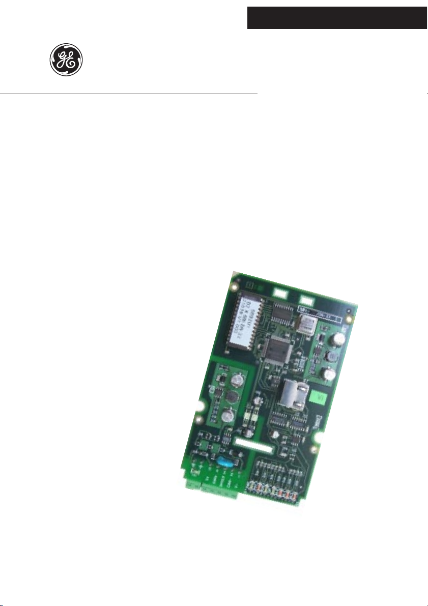
6KCV301DNET
DeviceNet interface board
for AV-300i Drives
INSTRUCTIONS
GE Industrial Systems
Page 2

Supersedes GEI-100435 Rev. 0.1 (10/99)
These instructions do not purport to cover all details or variations
in equipment, nor to provide every possible contingency to be met
during installation, operation, and maintenance. If further information is desired or if particular problems arise that are not covered
sufficiently for the purchaser’s purpose, the matter should be referred to GE Industrial Systems.
This document contains proprietary information of General Electric Company, USA and is furnished to its customer solely to assist that customer in the installation, testing, operation, and/or
maintenance of the equipment described. This document shall not
be reproduced in whole or in part nor shall its contents be disclosed to any third party without the written approval of GE Industrial Systems.
© 1999 by General Electric Company, USA. All rights reserved.
Page 3

6KCV301DNET
TABLE OF CONTENTS
1.0 INTRODUCTION ................................................................... 5
1.1 THE MANUAL ........................................................................................... 5
1.2 DEVICENET GENERAL DESCRIPTION ......................................................... 6
2.0 HARDWARE DESCRIPTION ................................................. 7
2.1 DIMENSIONS, WEIGHT, PROTECTION DEGREE........................................... 7
2.2 INSTALLATION ......................................................................................... 8
2.3 POWER SUPPLY ..................................................................................... 10
2.4 TERMINALS ........................................................................................... 10
2.5 LEDS ...................................................................................................... 10
2.6 TECHNICAL SPECIFICATION ................................................................... 11
2.7 INTERFACE ............................................................................................. 11
3.0 DEVICENET FUNCTION ...................................................... 12
3.1 OBJECT DESCRIPTION ........................................................................... 13
3.1.1 Object Model ................................................................................. 13
3.1.2 How Objects Affect Behavior. .......................................................... 14
3.1.3 Defining Object Interface ................................................................ 14
3.1.4 I/O Assembly Instances ................................................................... 15
3.1.5 I/O Assembly Data Attributes Format ............................................... 15
3.2 DATA TRANSFER VIA EXPLICIT MESSAGING .......................................... 15
3.2.1 Drive Parameter Access ................................................................. 16
3.2.1.1 Class code ...................................................................................... 16
3.2.1.2 Class attributes ............................................................................... 16
3.2.1.3 Instance Attributes ......................................................................... 16
3.2.1.4 Common Services ........................................................................... 16
3.2.1.5 Object Specific services .................................................................. 16
3.2.1.6 Behavior ......................................................................................... 17
3.2.1.6.1 Write Drive Parameter ................................................................ 17
3.2.1.6.1.1 Write Drive Parameter Request ............................................... 17
3.2.1.6.1.2 Write drive parameter - Reply OK ............................................ 18
3.2.1.6.1.3 Write drive parameter - Reply Error ........................................ 18
3.2.1.6.2 Read Drive Parameter ................................................................. 18
3.2.1.6.2.1 Read Drive Parameter Request ............................................... 18
3—————— TABLE OF CONTENTS ——————
Page 4

SIEI
3.2.1.6.2.2 Read drive parameter - Reply OK ............................................ 19
3.2.1.6.2.3 Read drive parameter - Reply Error ......................................... 19
3.2.2 DGF Option Parameter Access .......................................................... 19
3.2.2.1 Class code ...................................................................................... 20
3.2.2.2 Class attributes ............................................................................... 20
3.2.2.3 Instance Attributes ......................................................................... 20
3.2.2.4 Common Services ........................................................................... 20
3.2.2.5 Object Specific services .................................................................. 20
3.2.2.6 Behavior ......................................................................................... 20
3.2.2.6.1 Write DGF Parameter .................................................................. 21
3.2.2.6.1.1 Write DGF Parameter Request ................................................. 21
3.2.2.6.1.2 Write DGF parameter - Reply OK ............................................. 21
3.2.2.6.1.3 Write DGF parameter - Reply Error .......................................... 22
3.2.2.6.2 Read DGF Parameter .................................................................. 22
3.2.2.6.2.1 Read DGF Parameter Request ................................................. 22
3.2.2.6.2.2 Read DGF parameter - Reply OK .............................................. 23
3.2.2.6.2.3 Read DGF parameter - Reply Error .......................................... 23
4.0 POLLING FUNCTION ........................................................... 24
5.0 SETTING OF VIRTUAL DIGITAL I/O ..................................... 25
6.0 KEYBOARD INTERFACE...................................................... 26
6.1 MAIN MENU STRUCTURE ...................................................................... 26
6.1.2 Warning and error message handling ............................................. 26
6.2 SBI INFO MENU ...................................................................................... 27
6.2.1 Display node address (MAC ID) ...................................................... 28
6.2.2 Display Baud Rate .......................................................................... 28
6.2.3 Node status .................................................................................... 28
6.2.3.1 DeviceNet error types .................................................................... 29
6.2.4 Status of allocation ......................................................................... 31
6.2.5 CNXN status ................................................................................... 32
6.2.6 I/O CNXN status .............................................................................. 32
6.2.7 DUP MAC ID test (DMC) ................................................................. 33
6.2.8 Display Software version (Sotware version) ................................... 33
6.2.9 Display compatibility index(Compatib. index) .................................. 33
7.0 MISCELLANEOUS ............................................................... 34
7.1 DEFINITIONS ........................................................................................... 34
7.2 REFERENCES .......................................................................................... 34
—————— TABLE OF CONTENTS ——————4
Page 5

6KCV301DNET
1.0 INTRODUCTION
The manual describes the optional 6KCV301DNET card for connecting of
inverters and converters to DeviceNet networks.
A V300i drives can be connected in network through the 6KCV301DNET card.
This manual is intended for design engineeres and technicians responsible for
the maintenance, commissioning and operation of DeviceNet systems.
A basic knowledge of DeviceNet is assumed and may be found in the follow-
ing manuals:
- DeviceNet Specifications. Volume 1 - DeviceNet Communication Model
and Protocol (Issued by ODVA).
- DeviceNet Specifications. V olume 2 - DeviceNet Device Profiles and Object Library (Issued by ODV A).
1.1 THE MANUAL
Chapter 2 Dimensions, card mechanical installation, electric
connections and Dipswitch setting.
Chapter 3 DeviceNet functions: description of the objects
controlled by the card, data transfer via “Explicit
messaging”.
Chapter 4 “Polling” operations for the exchange of Drive pa-
rameters between the Master and the interface card
(M->S and S->M)
Chapter 5 Setting of virtual digital I/Os
Chapter 6 Keypad menus
Chapter 7 Definitions and references
—————— Interface card DeviceNet ——————
5
Page 6

GEI-100435A
1.2 DEVICENET GENERAL DESCRIPTION
DeviceNet is a profile of communication for industrial systems based on CAN.
As protocol CAN (ISO 11898) is used CAN2.0A with the 11 bit identifier .
The SBI card is developed as “Slave UCMM Capable Device” for operating
only in “Predefined Master/Slave Connection Set”.
The data transfer is carried out cyclically; the Master unit reads the data supplied by the Slaves and writes the Slave reference data; the Baud Rate supported by the SBI card are:
- 125 kbit
- 250 kbit
- 500 kbit .
The physical support is given by the RS485 serial line; a maximum of 64 Slaves
can be connected to the Bus.
6
—————— Interface card DeviceNet ——————
Page 7
6KCV301DNET
2.0 HARDWARE DESCRIPTION
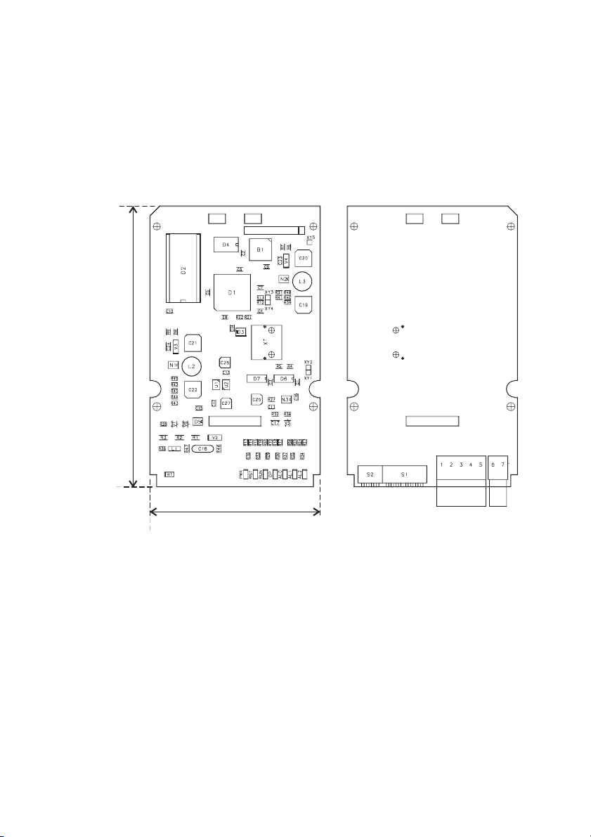
2.1 DIMENSIONS, WEIGHT, PROTECTION DEGREE
Component side Soldering side
SBI- /DN-33
145 mm [5,7“]
88 mm [3,4“]
BUS terminal Ground
Dimensions 145 [5.7”] x 88 [3.4”] x 30 [1.2]mm [in.] (H) x (W) x (D)
W eight 88 g [3.1 oz]
Protection degree IP00
—————— Interface card DeviceNet ——————
7
Page 8
GEI-100435A
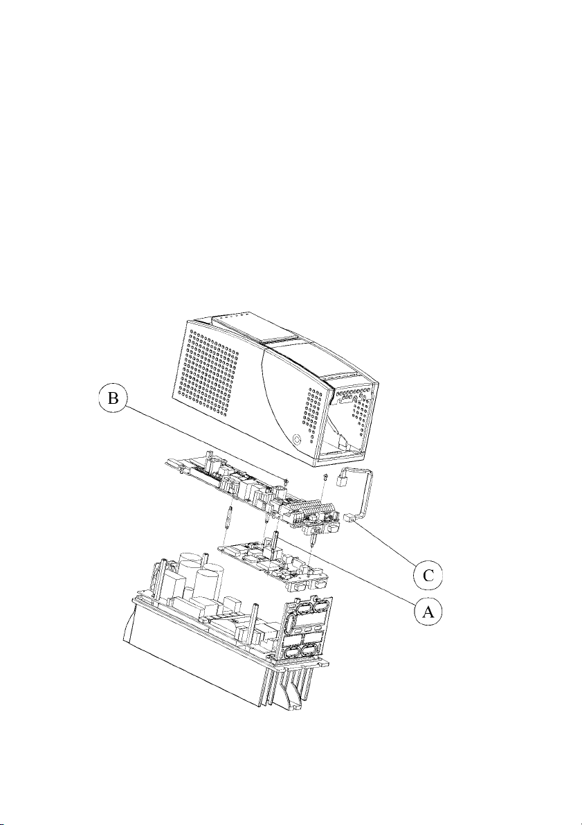
2.2 INSTALLATION
The SBI card is supplied with standoffs, screws, washers and a SBI-Drive link
cable provided with connectors.
1 . Switch the drive off.
2 . If the card is mounted inside the drive (see example below), fasten the SBI
card to the drive regulation card by means of screws (B) and standoffs
(A). The SBI-Drive link cable (C) must be connected between XT1 (on
Regulation card) and XT connector (on SBI card).
If the card is mounted outside the drive, the SBI card has to be fastened to
a DIN rail by using the external mounting kit; it is recommended to keep
the SBI card as close as possible to the drive. Do not put the SBI-Drive link
cable near power cables.
3. The SBI-Drive link cable is connected to the XT connector on the SBI-card.
8
—————— Interface card DeviceNet ——————
Page 9

6KCV301DNET
4. The Baud Rate of the SBI card is set via the Switches 7 and 8 of the
Dipswitch S1. The Baud Rate is detected only when the card is switched
on and it can be modified only by switching off and swtching on the card
again.Table 2 shows the relation between the DIP-Switches and the selectable Baud Rate value. The Default value is 125 Kbaud.
Switch 8 Switch 7 Baud Rate
OFF OFF 125 kBaud
OFF ON 250 kBaud
ON OFF 500 kBaud
ON ON 125 KBaud
DN21
.
5 . The switches 1..6 of the Dip-Switch S1 determine the address.
The address is only detected when the card is switched on. If the address
has been modified, the SBI card has first to be switched off and then on in
order assume the new address.
6. The Dip-Switch S2 determines the amount of words exchanged over the
Polling I/O. The table describes the relationship between the switches and
the number of Polling I/O words.
switch 4 switch 3 switch 2 switch 1 # of Polling I/O word
OFF OFF OFF OFF 1
OFF OFF OFF ON 1
OFF OFF ON OFF 2
OFF OFF ON ON 3
OFF ON OFF OFF 4
OFF ON OFF ON 5
OFF ON ON OFF 6
All Other 6
Combination
tdn0010
The Polling I/O word number is only detected when the card is switched on. If
the polling I/O word number has been modified, the SBI card has first to be
switched off and then on.
7 . Connect the Bus cable to the BUS terminal.
8 . Switch on the drive.
9 . The LEDS PWR and RUN light up.
10. Switch the Device Net power supply on; the LED H1 lights up.
11. The LED OP lights up when the Master/Slave connection has been established.
—————— Interface card DeviceNet ——————
9
Page 10
GEI-100435A
2.3 POWER SUPPLY
The power supply is provided by the XT connector which is also used to
transfer data between the SBI card and the drive regulation card.
Current draw: 350 mA
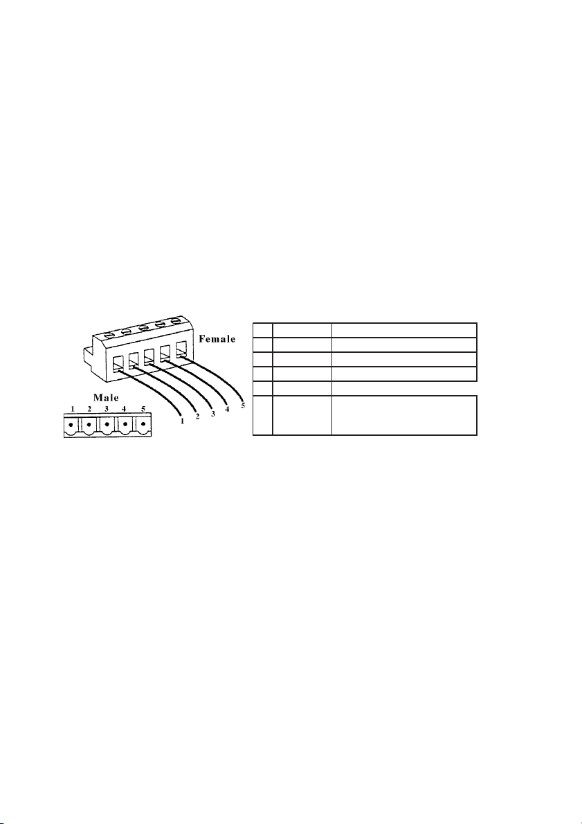
2.4 TERMINALS
Ground terminals (6-7) DeviceNet cable shield is connected to the ground
(PE) through these terminals.
T erminal BUS See the figure below. It allows to connect the SBI
card to the DeviceNet network. The pins are the
following:
Pin Signal Description
1 CAN_GND Ground / 0V /V2 CAN_L Can_L bus line (dominant low)
3 CAN_SHLD CAN shield
4 CAN_H CAN_H bus line (dominant high)
5 CAN_V+
CAN external positive supply
(dedicated for supply of
transceiver and optocouplers)
dn22
2.5 LEDS
PWR +5V power supply .
RST Reset active.
H1 +5V power supply on the RS 485 driver side. It is
supplied by the Bus.
RUN It is on when the microcontroller is operating.
OP It is on when the Master/Slave connection is es-
tablished.
AL0 It blinks when the “Duplicate MAC ID” test has
not been passed.
AL1, AL2 Not used and are always off.
10
—————— Interface card DeviceNet ——————
Page 11
6KCV301DNET
2.6 TECHNICAL SPECIFICATION
Storage temperature: -20°... +70°C (-68...+158°F)
Operating temperature: 0°... +55°C (32...+131°F)
Such temperatures are suitable to be used with those of the drive, which they
are connected to.
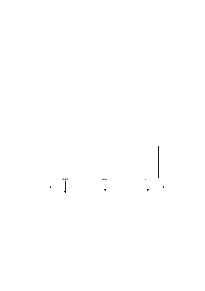
2.7 INTERFACE
For the mechanical connection, according to the internal or external mounting,
please use the kit and the mounting instruction sheet supplied with the card.
For the electrical connection please use the SBI-Drive link cable, also supplied.
For the connection to the Bus please use a shielded twisted cable recom-
mended by DeviceNet specification.
The connection among the single cards is accomplished by a shielded cable as
shown in the following figure:
6KCV301DNET
6KCV301DNET 6KCV301DNET
—————— Interface card DeviceNet ——————
PE
Shield
11
Page 12

GEI-100435A
3.0 DEVICENET FUNCTION
In this chapter are described the functions of DeviceNet managed by the SBI
card. The main characteristics of the card are:
1 . The card operates only as Slave in “Predifined Master/Slave Connection
Set”.
2. W ithin the “Predefined Master/Slave Connection Set” the card is a “UCMM
Capable Device”.
3 . The “Explicit Messaging” is managed.
4. The “Polling” for the fast cyclical data exchange Master/Slave is managed.
5 . The detection mechanism of the “Duplicate MAC ID” is implemented.
Regarding the “Explicit Messaging” the fragmentation of the data frame, with
a total of max. 38 byte, is managed.
Connection sizes
CONNECTION INSTANCE PRODUCED CONSUMED
Polled I/O
Explicit messaging 38 38
12
—————— Interface card DeviceNet ——————
Dependent on frame setting
tdn30020
Page 13

6KCV301DNET
3.1 OBJECT DESCRIPTION
Hereafter you find the description of the objects managed by the SBI card.
3.1.1 Object Model
The Fig. 3.11 shows the SBI card “Object Model”.
Application Objects
DGF par
Assembly Class
I/OI/O
Drive par
Message
Router
Connection
ExplicitI/O
Figure 3.1: DeviceNet Object Model
The following table shows:
1 . The object classes of the SBI-card.
2 . If the class is mandatory.
3. The number of instances included in every class.
See “DeviceNet Specifications” for the Standard classes.
IDENTITY
DeviceNet
—————— Interface card DeviceNet ——————
13
Page 14

GEI-100435A
Object Optional/Required # of Instances
Identity Required 1
Message Router Required 1
DeviceNet Required 1
Connection Required at maximum one Explicit
Assembly Optional 0..2
Drive Parameter Access Optional many
DGF Parameter Access Optional many
tdn0030ge
3.1.2 How Objects Affect Behavior.
The “Affect Behaviour” of the objects is reported in the following table:
Object
Identity
Message Router
DeviceNet
Connection
Assembly
Drive Parameter Access
DGF Option Parameter Access
Effect on Behavior
Supports “Reset Service”.
No effect
Port attributes configuration
Contains the number of logical ports
internal or external to the SBI board
Defines the I/O data format
Drive parameters read/write
DGF parameters read/write
3.1.3 Defining Object Interface
The object interface of the SBI card is the following:
Object Interface
Identity Message router
Message Router
DeviceNet Message router
Connection Message router
Assembly
Drive Parameter Access Message router
DGF Parameter Access Message router
Explicit Messaging
Connection Instance
I/O Connection or
Message Router
tdn0040ge
tdn0050ge
14
—————— Interface card DeviceNet ——————
Page 15

6KCV301DNET
3.1.4 I/O Assembly Instances
The following table identifies the “I/O Assembly” instances of the SBI card:
Number Type Name
195 Input PMSCS Assembly Cons
194 Output PMSCS Assembly Prod
DN325
3.1.5 I/O Assembly Data Attributes Format
The “I/O Assembly” attributes format for the Input is the following:
PMSCS Assembly Cons:
Instance Byte Bit 7 Bit 6 Bit 5 Bit 4 Bit 3 Bit 2 Bit 1 Bit 0
0
1
2
195
….
….
(n2)-1
n*2
(n) is the number of consumed Words; it depends on frame setting.
word #1 to consume, low byte
word #1 to consume, high byte
word #2 to consume, low byte
….
….
word #n to consume, low byte
word #n to consume, high byte
dn330
PMSCS Assembly Prod:
Instance Byte Bit 7 Bit 6 Bit 5 Bit 4 Bit 3 Bit 2 Bit 1 Bit 0
194
0
1
2
….
….
(n2)-1
n*2
word #1 to produce, low byte
word #1 to produce, high byte
word #2 to produce, low byte
….
….
word #n to produce, low byte
word #n to produce, high byte
dn335
(n) is the number of produced Words; it depends on frame setting.
3.2 DATA TRANSFER VIA EXPLICIT MESSAGING
The data transfer via Explicit Messaging is made through two new objects: one
for accessing the Drive parameters, the other to access the parameters of the
DGF option card.
—————— Interface card DeviceNet ——————
15
Page 16

GEI-100435A
3.2.1 Drive Parameter Access
For reading/writing the drive parameters the Drive Parameter Access object is
defined with the following characteristics:
- Class ID: 66h.
- Class Attribute: Revision
- Instance Attribute: This instance does not provide any attribute.
3.2.1.1 Class code
Class Code: 66hex
3.2.1.2 Class attributes
Number
1 Optional Get Revision UINT
Need in
implementation
Access Rule Name
3.2.1.3 Instance Attributes
Number
Need in
implementation
Access Rule Name
This instance does not provide attributes
3.2.1.4 Common Services
This object has no common services.
3.2.1.5 Object Specific services
Service
Code
32
hex
33
hex
Need in
implementation
Class Instance
n/a Required Get_Drive_Value Read drive parameter value
n/a Required Set_Drive_Value Writes drive parameter value
Service Name Description of Service
DeviceNet
Data Type
DeviceNet
Data Type
Description
of Attribute
Revision of
this object
Description
of Attribute
Semantics of
values
dn345
Semantics of
values
dn350
dn355
16
—————— Interface card DeviceNet ——————
Page 17

6KCV301DNET
3.2.1.6 Behavior
This object is the interface between the DeviceNet network and all Drive parameters. The access to the Drive parameter is carried out by the parameter
index; if the parameter does not exist or may not be accessed for any reason
(for example: try to write a read only parameter) an error code will be returned.
Drive parameters in text format cannot be accessed.
In the following are repeted patterns of how the data frame of data has to be
composed for reading/writing Drive parameters.
3.2.1.6.1 Write Drive Parameter
In this example the writing of a Drive parameter is shown; the cases of positive
or wrong writing are distinguished.
3.2.1.6.1.1 Write Drive Parameter Request
The data frame for writing a drive parameter is composed as follows:
DATA TYPE FIELD VALUE MEANING
Byte
See Note
Byte
1)
Byte or W ord depending on the type of allocation executed by the Master .
2)
The number of bytes of the “Value”-field depends on the length of the
Service
Code
Class ID 66hex
1)
Instance
2)
VA LU E
ID
33hex
XXXX
XX
XX
XX
XX
Set Drive Parameter -
Object Specific Service.
Drive Parameter Access
Class Object.
Drive Parameter Index in
format Low byte-High
byte.
Low byte-Low word drive
parameter value.
High byte-Low word drive
parameter value.
Low byte-High word drive
parameter value.
High byte-High word
drive parameter value.
dn360
Drive parameter; i.e.: if the Drive parameter type is “Integer” the length of
V ALUE is 2 bytes.
—————— Interface card DeviceNet ——————
17
Page 18

GEI-100435A
3.2.1.6.1.2 Write drive parameter - Reply OK
If the Drive parameter is written correctly, the response is:
DATA TYPE FIELD VALUE MEANING
Byte Service Code 33hex OR 80hex
Word Result 0000
Set Drive Parameter
Reply code- Object
Specific Service.
Result field equal to zero
means writing correctly
executed.
dn365
3.2.1.6.1.3 Write drive parameter - Reply Error
If the writing of the drive parameter has been rejected, the response is the
following:
DATA TYPE FIELD VALUE MEANING
Byte Service Code 33hex OR 80hex
Word Result
XXXX
Set Drive Parameter
Reply code- Object
1
Specific Service.
Drive specific error code.
dn370
1) For error codes see chapter 6.0
3.2.1.6.2 Read Drive Parameter
In this example is shown the reading of a Drive parameter; the cases of positive
or wrong reading are distinguished.
3.2.1.6.2.1 Read Drive Parameter Request
The data frame for the Drive parameter reading is composed as follows:
DATA
TYPE
Byte
See Note
See Note1)Instance
FIELD VALUE MEANING
1)
Service
Code
Class ID 66hex
ID
32hex
XXXX
Get Drive Parameter -
Object Specific Service.
Drive Parameter Access
Class Object.
Drive Parameter Index in
format Lowbyte-High
byte.
dn375
1) Byte or W ord depending on the type of allocation executed by the Master.
18
—————— Interface card DeviceNet ——————
Page 19

6KCV301DNET
3.2.1.6.2.2 Read drive parameter - Reply OK
If the Drive parameter is read correctly, the response is:
DATA TYPE FIELD VALUE MEANING
Byte
Word Result 0
Byte 1) XX
Byte 1) XX
Byte 1) XX
Byte 1) XX
Service
VA LU E
Code
32hex OR
80hex
Get Drive Parameter
Reply code- Object
Specific Service.
Result field equal to zero
means reading correctly
executed.
Low byte-Low word drive
parameter value.
High byte-Low word drive
parameter value.
Low byte-High word drive
parameter value.
High byte-High word
drive parameter value.
dn380
1) The number of bytes of the Value-field depends on the length of the Drive
parameter; i.e. if the Drive parameter type is “Integer” the length of V ALUE is 2
bytes.
3.2.1.6.2.3 Read drive parameter - Reply Error
If Drive parameter reading is rejected, the response is the following:
DATA TYPE FIELD VALUE MEANING
Byte
Word Result
Service
Code
32hex OR
80hex
XXXX
Get Drive Parameter
Reply code- Object
Specific Service.
1
Drive specific error code.
dn385
1) For error codes see chapter 6.0
3.2.2 DGF Option Parameter Access
For reading/writing the parameters of the DGF optional card the DGF Parameter
Access object is defined with the following characteristics:
- Class ID: 67h.
Class Attribute: - Revision
Instance Attribute: - This instance does not foresee any attribute.
—————— Interface card DeviceNet ——————
19
Page 20

3.2.2.1 Class code
3.2.2.2 Class attributes
GEI-100435A
Class Code: 67hex
Number
1 Optional Get Revision UINT
Need in
implementation
Access Rule Name
3.2.2.3 Instance Attributes
Number
Need in
implementation
Access Rule Name
This instance does not provide attributes
3.2.2.4 Common Services
This object has no common services.
3.2.2.5 Object Specific services
Service
Code
32
hex
33
hex
Need in
implementation
Class Instance
n/a
Required
n/a Required
Service
Name
Get_DGF_
Value
Set_DGF_
Value
3.2.2.6 Behavior
DeviceNet
Data Type
DeviceNet
Data Type
Description
of Attribute
Revision of
this object
Description
of Attribute
Description of Service
Read DGF option
parameter value
Writes DGF option
parameter value
Semantics of
values
dn345
Semantics of
values
dn350
Dn395ge
This object is the interface between the DeviceNet networkand all parameters
of the optional DGF card that can be mounted on the drive. The access to the
DGF parameter is made by the parameter index and the data type: if the parameter does not exist or cannot be accessed for any reason (i.e. try to write a read
only parameter) a specific DGF error code is returned.
Hereafter are reported patterns of how to compose the data frame for read/write
DGF parameters.
20
—————— Interface card DeviceNet ——————
Page 21

6KCV301DNET
3.2.2.6.1 Write DGF Parameter
In this example the writing of a DGF parameter is reported; cases of positive
and wrong writing are distinguished.
3.2.2.6.1.1 Write DGF Parameter Request
The data frame for writing a DGF parameter is composed as follows:
DATA TYPE FIELD VALUE MEANING
Byte
See Note
Byte
Service
Code
Class ID 67hex
1)
Instance
ID
Data Type
2)
N/U 00
VA LU E
33hex
XXXX
XX
XX
XX
XX
XX
Set DGF Parameter Object Specific Service.
DGF Parameter Access
Class Object.
DGF Parameter Index in
format Low byte-High
byte.
DGF specific data type
code.
Not used; has to be set to
zero.
Low byte-Low word DGF
parameter value.
High byte-Low word DGF
parameter value.
Low byte-High word DGF
parameter value.
High byte-High word
DGF parameter value.
dn3960ge
1) Byte or W ord depending on the type of allocation executed by the Master.
2) For codes see DGFC- manual.
3.2.2.6.1.2 Write DGF parameter - Reply OK
If the DGF parameter is written correctly, the response is:
DATA TYPE FIELD VALUE MEANING
Byte
Word Result 0
Service
Code
33hex OR
80hex
Set DGF Parameter
Reply code- Object
Specific Service.
Result field equal to zero
means writing correctly
executed.
—————— Interface card DeviceNet ——————
dn3970ge
21
Page 22

GEI-100435A
3.2.2.6.1.3 Write DGF parameter - Reply Error
If the writing of the DGF parameter is rejected, the response is:
DATA TYPE FIELD VALUE MEANING
Byte
Word Result
Service
Code
33hex OR
80hex
XXXX
Set DGF Parameter
Reply code- Object
Specific Service
1)
DGF specific error code
dn3975ge
1) For error codes see DGF-manual.
3.2.2.6.2 Read DGF Parameter
In this example the reading of a DGF-parameter is shown; the cases of positive
or wrong reading are distinguished.
3.2.2.6.2.1 Read DGF Parameter Request
The data frame for the reading of a DGF parameter is composed as follows:
DATA TYPE FIELD VALUE MEANING
Byte
See Note
Word
Byte
Byte N/U 0
Service
Code
1)
Class ID 67hex
Instance
ID
Data Type
2)
32hex
XXXX
XX
Get DGF Parameter -
Object Specific Service
DGF Parameter Access
Class Object
DGF Parameter Index in
format Low byte-High
byte
DGF specific data type
code
Not used; has to be set to
zero
dn3980ge
1) Byte or W ord depending on the type of allocation executed by the Master.
2) For data-type codes see DGF-manual.
22
—————— Interface card DeviceNet ——————
Page 23

6KCV301DNET
3.2.2.6.2.2 Read DGF parameter - Reply OK
If the DGF-parameter is read correctly, the response is:
DATA TYPE FIELD VALUE MEANING
Byte
Word Result 0000
Byte
Service
Data Type
VA LU E
32hex OR
Code
N/U 00
80hex
1)
XX
XX
XX
XX
XX
1) For data-type codes see DGF-manual.
Get DGF Parameter
Reply code- Object
Specific Service.
Result field equal to zero
means reading correctly
executed.
DGF specific data type
code.
Not used; has to be set to
zero.
Low byte-Low word DGF
parameter value.
High byte-Low word DGF
parameter value.
Low byte-High word DGF
parameter value.
High byte-High word
DGF parameter value.
dn3985ge
3.2.2.6.2.3 Read DGF parameter - Reply Error
If the reading of the DGF-parameter is rejected, the response is the following:
DATA TYPE FIELD VALUE MEANING
Byte
Word Result
Service
Code
32hex OR
80hex
XXXX
1) For error codes see DGF-manual.
—————— Interface card DeviceNet ——————
Get DGF Parameter
Reply code- Object
Specific Service
1)
DGF specific error code
dn3990ge
23
Page 24

GEI-100435A
4.0 POLLING FUNCTION
This type of DeviceNet-function is used for a fast cyclic exchange of Driveparameters between Master and SBI card.
The characteristics of the Polling-function are:
1. The data frame length is configurable through Dip-Switch and can vary
from 1 to 6 word for both directions (Slave->Master and Master->Slave).
From 1 up to 6 Drive parameters of one W ord each in Input and Output can
be transferred cyclically .
2. The card, as it is a Slave, during the Polling consumes Output data and
produces Input data as response.
The configuration of the Drive parameters transferred via Polling is set by
using configuration parameter allocated in the drive.
For the configuration of the Polling parameters, see the “OPTION 1” chapter of
the drive instruction manual.
24
—————— Interface card DeviceNet ——————
Page 25

6KCV301DNET
5.0 SETTING OF VIRTUAL DIGITAL I/O
The configuration of the Virtual Digital I/Os, is set by using configuration
parameter allocated in the drive.
For the configuration of the “Virtual Digital I/Os” see the “OPTION 1” chapter
of the drive instruction manual.
Remember that in this chapter the virtual digital inputs/outputs refer to the
Drive, it means that the Master can “write” the virtual digital inputs and
“read” the virtual digital outputs.
Virtual digital I/O are descrete signals which can be controlled by the master:
- 16 Input and 16 Output are available with the SBI card.
Virtual Dig I/O are thus an additional terminal strip:
Polling I/O Master>Slave Dig in
0
Enable
1
Start/stop
0
1
2
3
2
Jog+
3
Jog -
4
5
6
7
8
9
10
11
12
13
14
15
16
As for the digital terminals, before operating the virtual digital I/O, drive parameters must be assigned to the single terminal; in order to do this, please refer to
the “OPTION 1” chapter of the drive instruction manual.
Digital I/O value can be cyclically and fast transferred through the Polling I/O,
in order to do this, the virtual digit I/O value parameter must be assigned to one
of the Polling I/O words. Above picture shows that the virtual digital input has
been assigned to the Polling I/O Master>Slave Word 0. The example reports
also some drive signal assigned to the virtual digital input.
—————— Interface card DeviceNet ——————
25
Page 26

GEI-100435A
6.0 KEYBOARD INTERFACE
6.1 MAIN MENU STRUCTURE
This structure appears when the Enter key is pressed and “OPTION1” is displayed; in this case, keypad control passes to the SBI card.
OPTION 1
SBI INFO
SB3_8000
Move between the Menus by pressing the Cursor-Up/Cursor-Down keys and
use the Enter key to enter the currently displayed Menu. Pressing the Cancel
key in any displayed menu causes the “OPTION1” Menu to appear and keypad control returns to the Drive.
6.1.2 Warning and error message handling
Warning and error messages can be displayed on the first and second rows of
the keypad’s display; a maximum of 16 characters can be displayed per line.
The Cancel key must be pressed in order to clear these messages, at this point
the system automatically returns to the immediately superior Menu level.
26
—————— Interface card DeviceNet ——————
Page 27

6KCV301DNET
6.2 SBI INFO MENU
The keypad display shows either general purpose useful information (card
address, current Baud Rate, etc.) or information about the communication states
(node status, allocation status, etc.), in order to allow a fast troubleshooting if
the card can not be connected to the bus.
SBI INFO
MAC ID
XX
Baud Rate
XXX kBit
Node status
XX X
Status of alloc.
S:X A:X M:XXX
CNXN status
PE:X PP:X UE:X
IO CNXN status
XXX
DUP.MAC ID TEST
"text"
reserved - 1
XXXXXXXXXXXXX
Software version
V. X.XXX
Compatib. index
V XX.XX
DNM0040
By pressing the Cursor-Up/Cursor-Down keys it is possible to move through
the Menu items; the Cancel key allows to go back to the upper level Menus.
The first 8 information are automatically refreshed.
—————— Interface card DeviceNet ——————
27
Page 28

GEI-100435A
6.2.1 Display node address (MAC ID)
The node address (MAC ID), set by Dip-Switches, is displayed.
6.2.2 Display Baud Rate
The current Baud Rate of the node, set by Dip-Switches, is displayed.
6.2.3 Node status
The following node status are displayed:
· DNet Status.
· DNet StAux.
· DNet StUser.
By pressing the ENTER key , these three error-conditions are set to zero.
In normal conditions all must be set to zero; when pressing th ENTER key, all
error conditions are set to zero; if after this, the values are different from zero,
it means that an error occurred; even if these states are different from zero, the
PLC Master may be connected anyway.
28
—————— Interface card DeviceNet ——————
Page 29

6KCV301DNET
6.2.3.1 DeviceNet error types
DNetStatus Meaning
Code
0 No error exists
1 Resource not available
2 Value out of range
3 transportClass_trigger invalid
4 Invalid service for object state
5 Illegal message format
6 Invalid condition for transmission
7 Outstanding request exists
8 Object does not exist
9 Service not supported
1 0 Duplicate MacId check response received
1 1 Duplicate MacId check request received
1 2 Object not available
1 3 OpenAllIOCnxn failed
1 4 Duplicate MacId error
1 5 Time-out error
1 6 Software error
1 7 Message error
1 8 Hardware error
DnetStAux Meaning
Code
0 No additional information
1 All available group 2 message identifiers have been allocated
2 Invalid Ainitial_comm_characteristic@ attribute
3 All available group 1 message identifiers have been allocated
4 All available group 3 message identifiers have been allocated
5 Invalid value within the AtransportClass_trigger@ attribute
6 An Apply request is sent to a Connection instance when it is in
7 Illegal to send fragmented explicit Connection message
8 Connection object must be in Established state and must
9 Cannot send cnxn-based request since a request is outstanding
1 0 Invalid instance identifier specified in received explicit message
1 1 Explicit message request is directed at non-existent cnxn instance
1 2 A Create request can only be sent to the class, not a particular
1 3 ConfigCnxnndex already set
1 4 Unable to create cnxn class
1 5 Apply_attribute cannot be sent to the cnxn class, only a specific
1 6 Invalid service code received in explicit message request
1 7 Class specified in received Cnxn Based Explicit request message
the Established or Timed-out state
beMessaging type of Connection in order to send a cnxn-based
request
request
instance
instance
does not exist
—————— Interface card DeviceNet ——————
29
Page 30

GEI-100435A
1 8 More than 2 group 2 object have been created
1 9 Maximum number of allocatable group 3 identifiers already allo-
2 0 Group specified in open messaging connection is invalid
2 1 Invalid service code received in received ucmm request message
2 2 Duplicate MacId check response has been received
2 3 Duplicate MacId check request has been received
2 4 Cannot send open cnxn-based request since a request is outstanding
2 5 A connection within the client is not available
2 6 Timer Id not correct
2 7 expected_packet_rate not supported (is greater than maximum
2 8 No more Timer available
2 9 watchdog_timeout_action not correct
3 0 Watchdog time-out occured
3 1 UCMM time-out occured
3 2 Explicit time-out occured
3 3 Attempt to deallocate a CAN channel not allocated
3 4 No more CAN channel available
3 5 No more CAN channel available for transmission
3 6 CAN Interrupt register error
3 7 CAN is still in hardware reset
3 8 CAN status register error
3 9 Error on allocation
4 0 BusOff detected
4 1 Error on the-allocation
4 2 Too much data
4 3 Parameter object data type not correct
4 4 Connection path not correct
4 5 I/O length not correct
cated
allowed)
DnetStUser Meaning
Code
0 No error exists
1 No resource available
2 Duplicate MacId Check error
3 Illegal transmission
4 Illegal reception
5 Illegal action
6 Time-out error
7 Parameter error
8 DeviceNet is not enabled
9 DeviceNet module is not present or not ok
1 0 Hardware problem
0FFFFH General error
30
—————— Interface card DeviceNet ——————
Page 31

6KCV301DNET
6.2.4 Status of allocation
The following states of allocation are displayed:
1. S - Software state DNET ;1.the values, which this state can assume, are:
· 0 = initialization.
· 1 = Duplicate MAC ID Check in progress.
· 2 = Duplicate MAC ID Failed.
· 3 = Pre_Loop.
· 4 = Loop.
2. A - Bitmap of the allocations; the values are:
· 0 = No CNXN allocation.
· 1 = Explicit CNXN.
· 2 = Polled CNXN.
· 3 = Explicit + Polled CNXN.
3. M - MAC ID of the Master; the value is 255 if the Master has no allocation.
The following table shows the values of the single states corresponding to
specific operating conditions
TATUS ALLOCATION MAC ID
CONDITION
Normal functioning, the PLC
has not allocate connection yet
Normal functioning, the PLC
has allocate connections
Normal functioning, connections
goes on Timeout
Duplicate MAD ID Check in
Duplicate MAD ID failed
Pre_Loop (need some sec.) 3
1)
See DMC handling.
Progress
1)
S
0 255
4
1
1)
2
3
1
0 255
MasterMAC
—————— Interface card DeviceNet ——————
ID
dn6000
31
Page 32

GEI-100435A
6.2.5 CNXN status
The following states of the connections are displayed:
1. PE - Predefined Mode Explicit connection status .
2. PP - Predefined Mode Polled connection status .
3. UE - UCMM Explicit connection status.
Every single state can assume following values:
· 0 = does not exist.
· 1 = Configuring.
· 2 = W aiting for ID.
· 3 = Established.
· 4 = Timed-out.
· 5 = Deferred.
The following table shows the values of the single states corresponding to
specific operating conditions
CONDITION PE PP UE
Disconnected SBI card 0 0
Connected PLC 3 3
Disconnected PLC 3 4 or 0
1)
UE might have values different from zero occasionally for some seconds
1)
0
1)
0
1)
0
dn6010
from the allocation by PLC.
6.2.6 I/O CNXN status
The following states of the I/O connections are displayed:
1. E Expected Packet Rate; milliseconds indicating the Timeout, set by the
Master.
2. C Consuption Length; number of byte consumed (direction Master->Slave); set by the Master, for the card SBI depends on frame length.
3. P Produced Length; number of byte produced (direction Slave->Master) ;
set by the Master, for the card SBI depends on frame length.
32
—————— Interface card DeviceNet ——————
Page 33

6KCV301DNET
6.2.7 DUP MAC ID test (DMC)
The SBI card carries out a Test to check if there is another node with the same
address (Duplicate MAC ID) in the network; if there is a duplication of a node
address, the following message shows up:
DUP. MAC ID TEST
FAILED
In addition to this information, the red LED AL0 starts blinking.
In this case the address of the SBI card must be changed.
If the “Duplicate MAC ID” test is positive, the following message shows up:
DUP. MAC ID TEST
PASSED
This message means that the MAC ID is correct.
During the “Duplicate MAC ID” test, the following message shows up:
DUP. MAC ID TEST
IN PROGRESS - X
X is the current DMC state.
This test takes about two seconds; if the message remains, check cables,
connections and Baud Rate. See also the paragraph “Status of Allocation” to
display the Sw Dnet status.
6.2.8 Display Software version (Sotware version)
The Software version of the SBI card is shown.
6.2.9 Display compatibility index(Compatib. index)
The index of compatibility of the Software between the Drive and the SBI card
is shown.
—————— Interface card DeviceNet ——————
33
Page 34

GEI-100435A
7.0 MISCELLANEOUS
7.1 DEFINITIONS
- CAN Controller Area Network
- CNXN Connections
- C O S Change of State - DeviceNet operation mode
- DM C Duplicate Mac ID
- MAC ID Media Access Control Identifier (node address)
- ODVA Open DeviceNet Vendor Association
- UCMM Unconnected Message Manager
7.2 REFERENCES
- DeviceNet Specifications. Volume 1 - DeviceNet Communication Model
and Protocol (issued by ODVA)
- DeviceNet Specifications. Volume 2 - DeviceNet Device Profiles and Object Library (issued by ODV A )
- A V300i Instruction manual
- 6KCV301DGF Instruction manual
34
—————— Interface card DeviceNet ——————
Page 35

Page 36

6KCV301DNET 10/99
Rev. 0.2 - 21.8.2000
We bring good things to life.
GEI-100435A Rev. 0.2 (08/00)
GE Industrial Systems
Internet Address: http://www.ge.com
 Loading...