

Page 1
6KCV301DGF
Digital General Function Card
for AV-300i Drives
INSTRUCTIONS
GE Industrial SystemsGE Industrial Systems
Page 2

These instructions do not purport to cover all details or variations in
equipment, nor to provide every possible contingency to be met during
installation, operation, and maintenance. If further information is desired
or if particular problems arise that are not covered sufficiently for the
purchaser’s purpose, the matter should be referred to GE Industrial
Systems.
This document contains proprietary information of General Electric
Company, USA and is furnished to its customer solely to assist that
customer in the installation, testing, operation, and/or maintenance of
the equipment described. This document shall not be reproduced in
whole or in part nor shall its contents be disclosed to any third party
without the written approval of GE Industrial Systems.
© 1999 by General Electric Company, USA. All rights reserved.
Page 3

Table of contents
1. GENERAL DESCRIPTION ..................................................................6
1.1 INTRODUCTION .................................................................................... 6
1.2 HARDWARE DESCRIPTION .................................................................. 7
1.2.1 MEMORY MAP .............................................................................................. 7
1.2.2 SERIAL LINE RS-485 ...................................................................................... 8
1.2.3 LEDS ............................................................................................................ 11
1.2.4 JUMPERS .................................................................................................... 12
1.2.5 CAN CONNECTOR ........................................................................................ 13
1.3 MECHANICAL LAYOUT ....................................................................... 14
2. DGF OVERVIEW ..............................................................................15
2.1 INTRODUCTION .................................................................................. 15
2.1.1 Firmware organization ................................................................................. 15
2.1.2 DGF application ............................................................................................ 16
2.1.2 Working of the DGF ..................................................................................... 17
2.1.3 Global organization of the DBASE ................................................................ 19
2.1.4 Parameters and variables ............................................................................ 22
2.1.4.1 Initialization of the General variables ............................................ 23
2.1.4.2 Data management inside the DBASE ............................................ 23
2.1.4.3 Access to a parameter from the external world ............................ 23
2.1.4.4 Storage of the parameter and of the associated record ................ 24
2.1.5 FVAR, IVAR and NUM .................................................................................. 26
2.1.6 DPRAM organization .................................................................................... 26
2.1.6.1 DPRAM hardware ......................................................................... 27
2.1.6.2 DPRAM software organization ...................................................... 27
2.2 DGF STATUS ....................................................................................... 29
2.2.1 Status commands ........................................................................................ 31
2.2.2 Alarms ......................................................................................................... 32
2.2.2.1 Alarm code from the drive ............................................................. 36
2.2.2.2 Severe alarm ................................................................................. 36
2.3 DATA FORMATS .................................................................................. 38
2.3.1 Description of base-10 floating point ........................................................... 38
2.3.1.1 Shreal format ................................................................................ 38
2.3.1.2 Slreal format ................................................................................. 39
Page 4

2.3.1.3 S3hreal format .............................................................................. 39
2.3.1.4 S3LREAL format ............................................................................ 39
2.4 INTERFACE.......................................................................................... 40
2.4.1 Drive keypad ................................................................................................ 40
2.4.2 DGF Serial line ............................................................................................. 47
2.4.2.1 HIBS .............................................................................................. 47
2.4.3 DRIVE SERIAL LINE ...................................................................................... 47
2.4.4 DeviceNet .................................................................................................... 47
2.4.5 Serial bus interface (SBI) ............................................................................. 47
2.5 DRIVE PARAMETERS .......................................................................... 48
2.6 PARAMETER DESCRIPTION ............................................................... 49
2.6.1 List of parameters ........................................................................................ 49
2.6.2 Description of parameters ........................................................................... 51
2.6.2.1 Identification parameters .............................................................. 51
2.6.2.2 DPRAM parameters ...................................................................... 52
2.6.2.3 I/O configuration ........................................................................... 53
2.6.2.4 Mode configuration ....................................................................... 53
2.6.2.5 Can controller parameters (DeviceNet) ........................................ 53
2.6.2.6 System parameters ....................................................................... 53
2.7 HOW TO CONFIGURE THE DGF........................................................... 57
2.7.1 Which method to use .................................................................................. 57
2.7.2 First configuration of DGF ............................................................................ 57
2.7.3 Mode configuration ...................................................................................... 57
2.7.4 Basic transition ............................................................................................ 57
2.7.5 Working mode ............................................................................................. 58
2.7.6 Serial address .............................................................................................. 59
2.7.7 DP-RAM ....................................................................................................... 59
2.7.8 I/O configuration .......................................................................................... 59
Page 5

List of tables and figures
1. GENERAL DESCRIPTION ..................................................................6
Figure 1.2.1: 6KCV301DGF connections ............................................................................ 7
Figure 1.2.1.1: 6KCV301DGF memory map........................................................................ 8
Figure1.2.1.2: 6KCV301DGF flash Eprom memory map ..................................................... 8
Figure 1.2.2.1: RS-485 interface ....................................................................................... 9
Figure 1.2.2.2: RS-485 single point comm. without signal isolation ................................ 10
Figure1.2.2.3: RS-485 communications with signal isolation .......................................... 10
Figure 1.2.4.1: 6KCV301DGF Jumper Locations .............................................................. 12
Figure 1.3.1: DGF Location .............................................................................................. 14
2. DGF OVERVIEW ..............................................................................15
Figure 2.1.1: DGF block diagram ..................................................................................... 15
Figure 2.1.1.1: Logical structure ...................................................................................... 16
Figure 2.1.2.1: DGF Program Structure............................................................................ 19
Figure 2.1.7.1.1: DPRAM Hardware ................................................................................ 27
Figure 2.2.1: Logic of DGF status ..................................................................................... 29
Table 2.2.1: Leds status ................................................................................................... 31
Table 2.2.2.1: DGF alarm codes ....................................................................................... 33
Table 2.2.2.2: Alarm code 2 (AL_DPRAM)cause ............................................................. 33
Table 2.2.2.3: Alarm code 6 cause .................................................................................. 34
Table 2.2.2.4: Alarm code 14 (AL_BRICKS_DP) cause ................................................... 35
Table 2.2.2.5: Alarm code 15 (AL_REGISTER) cause ...................................................... 35
Table 2.2.2.6: Alarm code 16 (AL_CCZ) cause ............................................................... 35
Table 2.2.2.7: Alarm code 22 (AL_DNET) cause ............................................................. 36
Figure 2.4.1: DGF Communication ................................................................................... 40
Page 6

GEI-100430
1. GENERAL DESCRIPTION
1.1 INTRODUCTION
The optional Digital General Function Card (DGF) is mounted on the AV300i drives
for special functions such as winder/unwinder control, positioning, etc. It connects
with the drive regulation card via the connector for an optional card. The connection
with the drive also provides the power supply for the DGF.
The communication between the two cards uses a 2Kbytes dual-port ram (DPRAM).
The 6KCV301DGF card is based on an Intel 80C386EX-25 with a numerical processor
80C387SX-25.
The standard user communication on the card is RS-485 serial link.
It is possible to mount an option module with CAN controller for DeviceNet
communication.
It is also possible to read and write DGF parameters using all the drive communications
[serial link, local keypad and an additional optional communication card (e.g. GENIUS,
INTERBUS-S or PROFIBUS-DP)]. All these communications use the drive
microprocessor and DPRAM.
This manual comprises four chapters:
- Chapter 1 describes the DGF hardware. Its installation and configuration settings
are detailed. Settings for serial communications are explained.
- Chapter 2 details the software architecture of the DGF. It describes the MARTE
operating system, task organization, DGF parameters and variables, the five card
status states, and the DGF alarm conditions. Permissible data formats are described.
Drive keypad programmer operation is also described.
- Chapter 3 describes the HIBS software, which is used to download compiled user
programs to the DGF Card ; it is also used to load .BLK files (explained in chapter
4) to create supervision pages to monitor drive operation.
- Chapter 4 details .BLK file syntax. The .BLK file is an ASCII file which is used
to configure DGF DPRAM (Dual-Ported Random Access Memory) and create
supervision pages.
6
—————— Digital General Function Card ——————
Page 7

6KCV301DGF
1.2 HARDWARE DESCRIPTION
The power supply is external to the card and comes directly from the drive.
The DGF is defined as the option 2 card in the drive
A module with DNet interface can be mounted on the 6KCV301DGF card, if desired.
The main 6KCV301DGF hardware characteristics are:
- Intel “embedded” 80386EX 25MHz microprocessor
- Numerical processor 80387 SX 25MHz
- Two static RAM memories (128Kword)
- A FLASH-EPROM boot block memory (256Kword)
- 2 Kbytes serial EEPROM
- VPP signal 12V circuit generator for flash clear/programming
- Microprocessor supervisory circuit for supply surveillance and reset generation
- Serial link RS-485 with SLINK3 protocol.
- 2 Kbytes DPRAM (Dual Port Ram)
- CPU OK (Hardware Watchdog)
- Led for PWR, RST,VPP,CPU OK, CAN and status
The following picture shows the connections between 6KCV301DGF card and the
other cards.
AV-300i Regulation card DGF card
RV33-1
X0 X0
1
1
36
36
Dnet
DeviceNet
(optional)
RS485
(S-LINK3)
Figure 1.2.1: 6KCV301DGF connections
1.2.1 MEMORY MAP
The RAM address must start at 0:0 because the vector interrupts area is in the lowest
address. The flash EPROM must be mapped on the top area because the reset address
is FFFF:0. The DPRAM is mapped at the end address of RAM area.
—————— Digital General Function Card ——————
7
Page 8

GEI-100430
MEMORY MAP
FFFF:FH
FLASH EPROM
8000:0H
4800:0H
DPRAM
SRAM
Figure 1.2.1.1: 6KCV301DGF memory map
The flash EPROM boot-block programming is done once at time of manufacture.
Thereafter, all the software is downloaded using the boot code and the serial link.
The firmware is loaded starting from the first main block (8000:0H) while the data
block will be used to save parameters and block information.
DGFC-386: FLASH MEMORY MAP
4000:0H
0000:0H
FFFF:FH
BOOT BLOCK
DATA BLOCK 2
DATA BLOCK 1
MAIN BLOCK 3
MAIN BLOCK 2
MAIN BLOCK 1
MAIN BLOCK
FC00:0
FA00:0
F800:0
E000:0H
C000:0H
A000:0H
8000:0H
Figure1.2.1.2: 6KCV301DGF flash Eprom memory map
1.2.2 SERIAL LINE RS-485
The RS-485 interface allows data transfer using a two-wire twisted conductor with
shield. The transfer rate is 9.6 Kbaud. The serial link circuit is the same of the drive.
For download applications programs directly to the RS485 port, use a 6KCV300CTI
and a standard 9 pin m/f cable.A 9-socket female connector allows communication
with an external device in a multidrop configuration. The serial link may be used either
with or without signal isolation. When using signal isolation an external power supply
is necessary for 5V. This is the default configuration. The configuration without signal
isolation is possible only with short connections and with HIBS during the card
8
—————— Digital General Function Card ——————
Page 9
6KCV301DGF
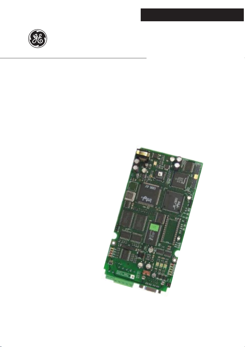
configuration. When you use RS-485, the line terminator resistors are connected through
S23 and S24 jumpers and must be ON only on the line end device. The protocol used
is SLINK3, detail provided in separate manuals.
X3
470R
470R
0VS
+5VS
120R
S23
S24
TXB/RXB
TXA/RXA
100R
GND
+5V
5
9
4
8
3
7
2
6
1
Figure 1.2.2.1: RS-485 interface
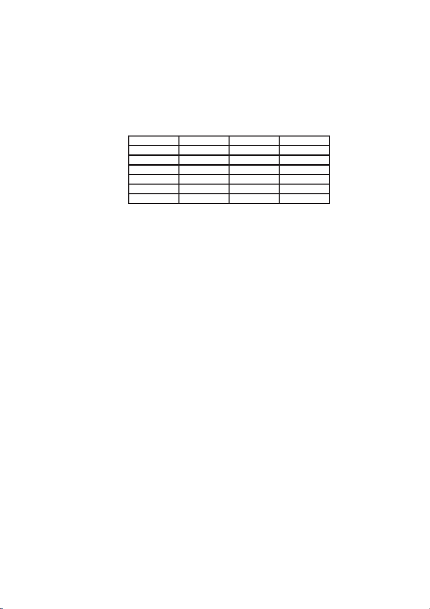
Pin Signal Description
1
2
3 RXA/TXA (+) Positive differential I/O
4 GNDS
5 GNDS 0V External power supply
6 +5V
7 RXB/TXB (-) Negative differential I/O
8 GND
9 +5VS 5V External power supply Max 120 mA
- Reserved
Connected with pin 8 GNDS with 110 ohm for
equipotential connection
Internal +5V . You need to join with pin 9 for internal
supply
Internal GND. You need to join with pin 5 for internal
supply
d0010g
In this configuration you need to join pin 5 with pin 8 and pin 9 with pin 6 of X3
connector. DGF connectors are female connectors.
The configuration without signal isolation is possible only with short connections: for
example, with HIBS during the card configuration. On the drive, you need to use
signal isolation as described below.
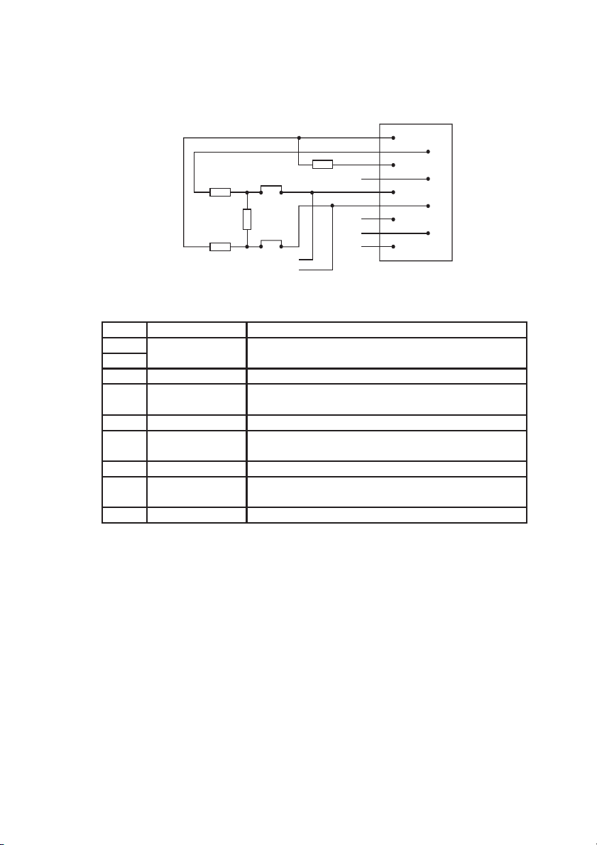
Figure 1.2.2.2 shows a single-point connection between a PC or PLC RS-232 interface
and one 6KCV301DGF.
An adapter RS-232/485 is necessary to convert the PC RS-232 COM to an RS-485
signal. A simple two wire twisted cable is necessary to transmit the RS-485 differential
signals TXA/RXA - TXB/RXB.
—————— Digital General Function Card ——————
9
Page 10
DGFC
X3 RS485
59 6837
GEI-100430
S23=ON
S24=ON
RS485
RS232
RS232
PC/PLC
Figure 1.2.2.2: RS-485 single point comm. without signal isolation
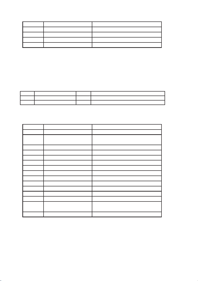
The DGF jumpers are:
Name Default Function
S23 ON "ON" RS-485 line end device (for terminal resistor)
S24 ON "ON" RS-485 line end device (for terminal resistor)
d0020g
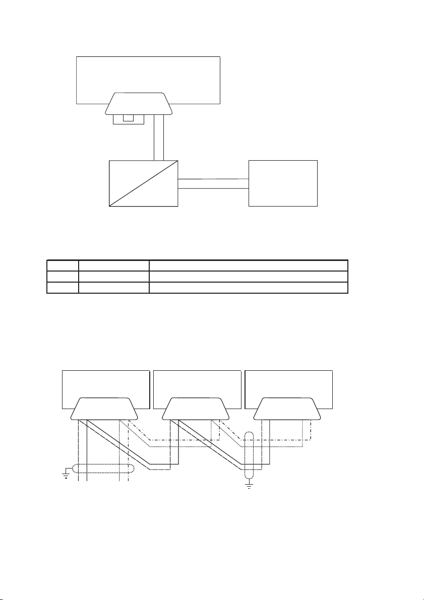
Figure 1.2.2.3 shows an RS-485 communications link with three 6KCV301DGF cards
with signal isolation.This is the recommended configuration for applications that use
the serial link. The card at the end of the line (both ends) must have the terminator
resistor inserted, and thus S23=S24=ON while the other two 6KCV301DGF cards
must have S23=S24=OFF.
DGFC DGFC DGFC
59 37 59 37 59 37
S23=OFF
S24=OFF
X3 RS485 X3 RS485 X3 RS485
S23=OFF
S24=OFF
S23=ON
S24=ON
+5V
RS485
COM
Figure1.2.2.3: RS-485 communications with signal isolation
DGF connectors are female connectors. In this configuration, all 6KCV301DGF cards
need external power supply for serial interface.
10
—————— Digital General Function Card ——————
Page 11
6KCV301DGF
1.2.3 LEDS
The LEDs on 6KCV301DGF card have the following meanings:
Name Color Function if LED ON
PWR Green Power 5V
RST Red Reset
OK Green Hardware watchdog = OK
VPP Green Flash eprom programming voltage
PRG Green Flash eprom programming voltage command
H1 Yellow Status LED 1 (see table 2.2.1)
H2 Red Status LED 2 (see table 2.2.1)
H3 Red Status LED 3 (see table 2.2.1)
H4 Red Status LED 4 (see table 2.2.1)
d0030g
PWR is on when 5V supply is present; this LED must be always on when the regulation
board of the drive is supplied.
RST led indicates that a hardware reset occurs. This LED is always OFF; the only
operation that puts the LED ON briefly is the power on and off operation
during the firmware download sequence.
OK is always ON during normal operation and indicates that the card is working
normally. If it is OFF during normal operation, this indicates a card malfunction;
this condition forces an alarm on the drive. The LED should be OFF only
during the firmware download sequence.
VPP indicates the presence of the flash eprom programming voltage (12V). This
LED must be ON only during the firmware download sequence or during the
archive operation (save parameters).
PRG indicates the enable of the flash eprom programming voltage generation. This
LED must be ON only during the firmware download sequence or during the
archive operation (save parameters).
H1 – H4 These LEDs are controlled by the software of the card. Refer to Chapter 2 for
additional information.
—————— Digital General Function Card ——————
11
Page 12
GEI-100430
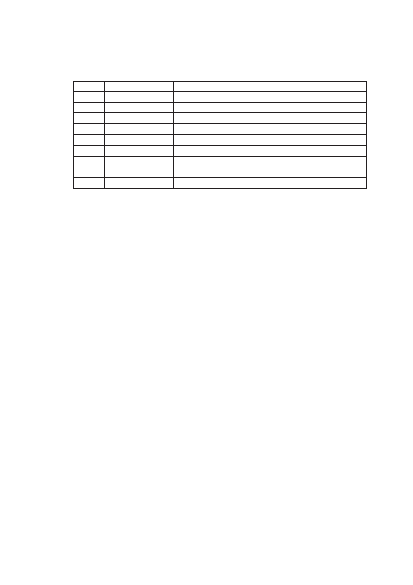
1.2.4 JUMPERS
The following table shows the 6KCV301DGF jumpers:
Name Default Function
S7 OFF Reserved (NMI)
S17 OFF Reserved (hardware reset)
S23 ON
S24 ON
S27 A Reserved
S28 OFF Reserved
The only jumpers that it is possible to move are the RS-485 serial link jumpers. For
more information see section 1.2.2.
ON only on the RS-485 line end device (for terminal
resistor)
d0040ge
12
Figure 1.2.4.1: 6KCV301DGF Jumper Locations
—————— Digital General Function Card ——————
Page 13
6KCV301DGF
1.2.5 CAN CONNECTOR
The DNet (CAN) interface provides signal isolation and uses a 4- wire cable : two for
signals and two for external power supply. The 6KCV301DGF connectors have the
following meanings:
Pin Signal Description
1 V- Negative external power supply
2 CAN- Negative CAN signal
3 SHIELD Cable shield
4 CAN+ Positive CAN signal
5 V+ Positive external power supply
6
7
Note that the line terminator resistor is external to the card according to DeviceNet
specification.
GND Ground: connect to ground
d0050g
—————— Digital General Function Card ——————
13
Page 14

GEI-100430
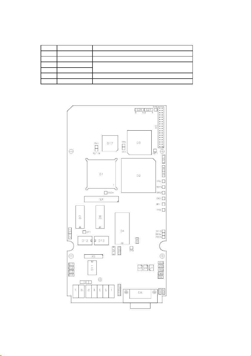
1.3 MECHANICAL LAYOUT
Figures 1.3.1 shows the location of the 6KCV301DGF card on the drive. The DNET
module are optional and therefore they may not be present. The connector connects
only the Drive Regulation Board to DGF.
For more information about the connections see Figure 1.2.1 of this manual.
Regulation board
14
DGF card
DNET module
Figure 1.3.1: DGF Location
—————— Digital General Function Card ——————
Page 15
6KCV301DGF
2. DGF OVERVIEW
2.1 INTRODUCTION
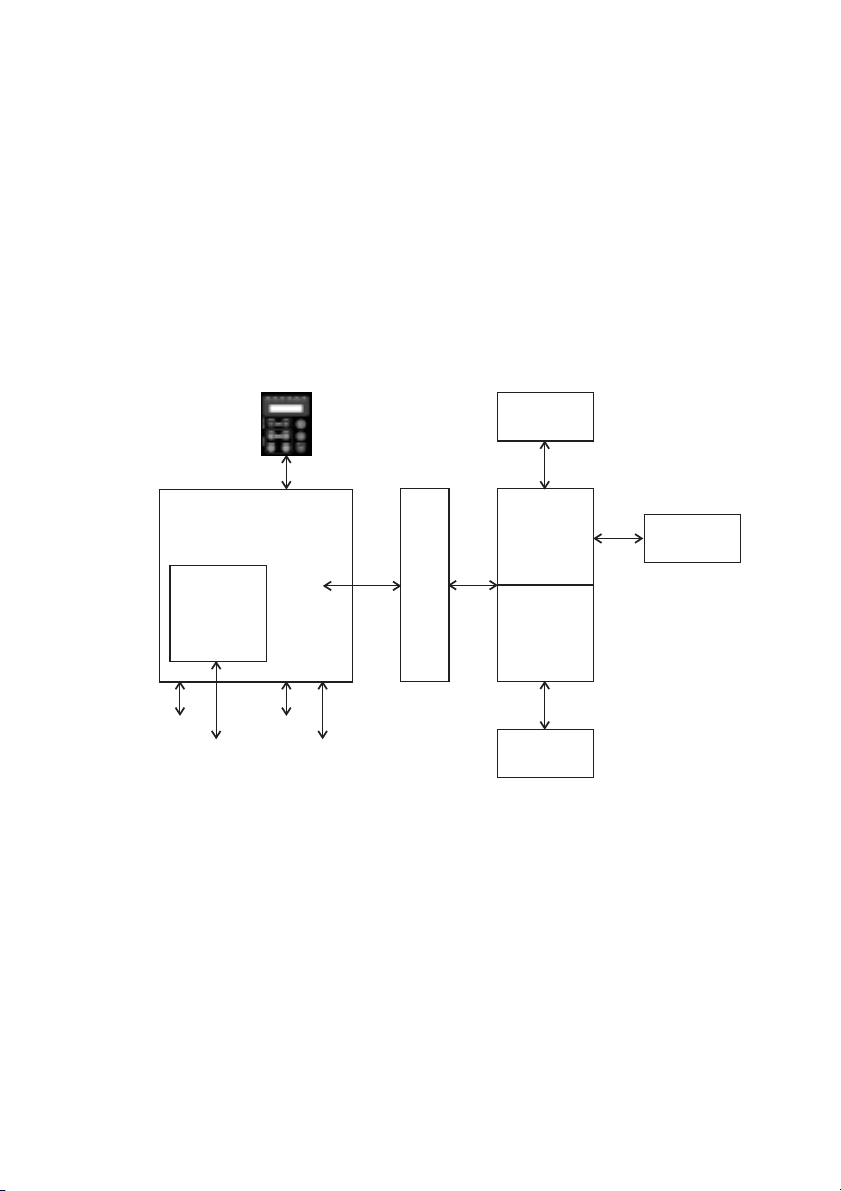
DGCF is a general purpose, where the final user can load the custom firmware which
carry out the desidered applications.
The DGF option is mounted on the drive with which it communicates through a DUAL
PORT RAM. Therefore it is possible to read drive parameters (including parameters
connected to analog and digital I/O), perform the algorithms, and write the result or
other parameters necessary to realize the desired functions.
The functional blocks also allow the reading of inputs and writing of outputs, physically
present on the optional I/O card and available to the DGF.
I/O
Firmware
D
Standard
Dbase
P
R
Communication
card
Analog I/O
Serial Link
(Profibus-DP, Interbus-S,...)
DRIVE
Digital I/O
Serial Link
(Slink3)
A
M
User
HIB
Figure 2.1.1: DGF block diagram
2.1.1 Firmware organization
The firmware of the DGF is divided in two parts: a fixed part, factory developed, and
a personalized one which can be developed even by the final user.
The final user has different possibilities to personalize the firmware of the DGF. The
main tools are the developing environment Win+Drive. Users with a programming
knowledge can develop directly with a C or Assembler language.
—————— Digital General Function Card ——————
15
Page 16
GEI-100430
2.1.2 DGF application
Application code can be obtained these ways:
1 Graphical development tool Win+Drive and design the specific application.
2 Graphical development tool Win+Drive and a factory predeveloped application.
The standard application can be modified with Win+Drive according to the specific
needs.
3 Use a factory developed and tested application and load it on the DGF unmodified.
In this case the Win+Drive can be used.
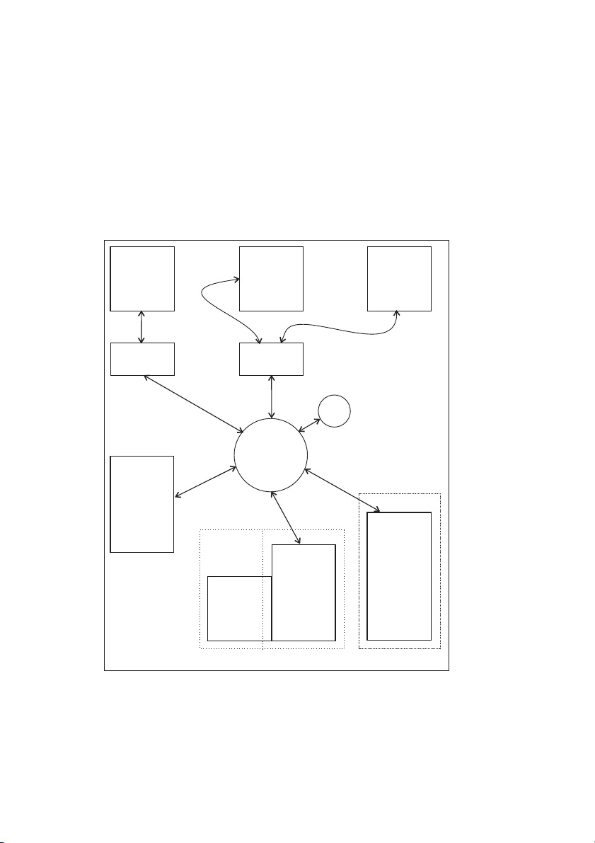
4 Demo version
DRIVE PC
SLINK3
DPRAM
I/O
OPTIONAL
CARD
ARCHIVE
DBASE
EEPROM STORE AREA DBASE AREA
CAN
Controller
COPROCESSOR
387
386
Firmware
DBASE
Figure 2.1.1.1: Logical structure
NUCLEUS & FIRMWARE The firmware core of the DGF consists of the operati-
ve system multi-task real time MARTE. The core regulates the
times and the task priorities forming the firmware.
16
—————— Digital General Function Card ——————
Page 17

6KCV301DGF
CPM Mathematical co-processor 387.
DPRAM DPRAM is a bi-accessible storage device that allows the DGF
to communicate with the connected drive. Various connection
structures are available, with different exchange capacity and
priority.
I/O OPTIONAL CARD It is possible to add additional cards to expand the
hardware capability of the DGF. The detailed description of
these devices can be found in their specific documentation.
The DGF can be provided with various I/O cards.
DBASE DBASE is a block used for the communication with the external
world. It is a catalog of variables provided by the DGF and
containing different information on the system. For each
variable access modes are specified, for example:
- read-only or read and write
- limits of the variable value
- access level, etc.
All information coming from or directed to the external world
goes through DBASE.
ARCHIVE Archive is a particular storage area where DBASE data are
stored so that the DGF can restart after a supply voltage failure.
2.1.2 Working of the DGF
The software of the card is based on the multi-task real-time operating system called
MARTE.
The structure of the program comprises a nucleus of 5 tasks with the following
characteristics (see Figure 2.1.3.1):
TASK SYN DPRAM This task executes the communications with the drive, for the
parameters at high priority , using the SYN DPRAM structure
of the DPRAM. The connection is executed with the maximum
priority at constant frequency. The event which wakes up the
task is a signal coming from the drive, whose execution is
synchronous with the regulation task of the drive.
TASK PERIOD This task carries out the regulation program developed by the
user. The task is normally carried out as a sub-routine of the
task SYN DPRAM. As a consequence, it inherits the main
characteristics:
- execution at the maximum priority ,
- constant priority
- synchronous with the drive.
In particular applications the task could be carried out in an independent way from the
task SYN DPRAM. In this case the execution of the task is carried out in an
asynchronous, with respect to the drive.
—————— Digital General Function Card ——————
17
Page 18

GEI-100430
The execution cycle of the above-mentioned two tasks is fixed through a parameter
and can vary from 2 to 20 milliseconds with a tick of 2 milliseconds. The reason the
execution time of these important tasks is variable is that the TASK PERIOD carries
out the program developed by the user, and is dependant on the size of the custom
application program. A later chapter explains how to choose a correct execution time.
T ASK MEDIUM This task executes code with medium importance; in the futu-
re parts of the user-developed program will be allowed to
execute in this task. The execution time is fixed at 50
milliseconds.
T ASK ASYN DPRAM This task in the applications code executes with the drive for
the parameters at low priority, using the structure ASYN
DPRAM of the DPRAM. The connection is carried out
asynchronous from the regulation task of the drive.
T ASK POLLING This task carries out checks of very low importance. The
execution time is fixed at 500 milliseconds. The DGF interacts
with the external environment through two devices:
DRIVE DGFCy Can read and write some parameters of the drive and through
these modify the working of the drive. Moreover, the DGF
has the ability to manage directly the physical I/O of the drive.
For additional information, refer to section 2.1.7.
I/O CARDS If the physical I/O of the drive is insufficient for the application
it is possible to add additional optional cards with specific
functions. Further information is given in their respective
documentation.
The DGF operation can be configured through DGF parameters. The access from the
external world to these parameters is managed by the DBASE. The DBASE is a set of
procedures and data which coordinates and manages the access to DGF parameters.
The DBASE is the interface between the operating system of the DGF and the external
world. The devices which can access the DBASE
of the DGF are the following:
- Serial port RS-485 of the DGF in modality SLINK2, SLINK3 and SLINK4
- Serial port RS-232 of the DGF in modality SLINK2, SLINK3 and SLINK4
- Serial protocol DeviceNet
- Drive keypad from the application card or Opt 2 menu
- Optional communication cards on the drive
- Serial port RS-485 of the drive in modality SLINK3 for DGF
Further information regarding the DBASE is given in section 2.1.6.
18
—————— Digital General Function Card ——————
Page 19

6KCV301DGF
s
e
m
c
)
0
0
5
(
G
N
M
I
A
R
L
P
L
D
O
P
S
K
A
S
Q
A
L
T
C
A
T
5
0
(
N
Y
E
M
K
S
S
A
T
J
B
U
I
D
E
P
K
Q
L
C
O
-
D
P
M
(
2
D
O
I
R
D
N
Y
S
MARTE
W
m
s
e
c
)
.
/
.
2
0
m
s
P
e
R
c
A
M
DEFINED
FVAR
IVAR
NUM
D
B
A
S
E
SLINK3
SLINK2
DNET
CLQ SLINK3 DPRAM
KEY DRIVER (DPRAM)
SER1
SER2
SER1
SER2
DNET
SER
DRIVER
Figure 2.1.2.1: DGF Program Structure
2.1.3 Global organization of the DBASE
The DBASE is a set of data and procedures which regulates the parameter management of the DGF . For each parameter that has been put in the DBASE, an associated a
record of information which describes the parameter has been created:
-IP A parameter’s identifier.
-UNM 4-character label defining the measure unit of the parameter .
-DESCRIBE 10-character array which contains the parameter’s name.
-TYPE specifies the type of the parameter.
-PROCEDURE if this field is not 0, it is a procedure that will be carried out
each time the parameter is read or written.
-MINIMUM minimum value of the parameter .
-MAXIMUM maximum value of the parameter.
-LIMIT MINIMUM minimum limit of the attribute MINIMUM.
-LIMIT MAXIMUM maximum limit of the attribute MAXIMUM.
-STATUS OF ACCESS it specifies the modes of access for the reading and writing
of the parameter.
- LEVEL OF ACCESS it specifies the level of the password to enter into the parameter
modification.
-MEMO it specifies the storage modes of the parameter.
-DEFAULT parameter’s default value .
The collection of these records forms the DBASE area. For storage reasons, that will
be explained below, this area is multiplied 4 times.
- DBASE_RAM working area
- DBASE_ROM area in which the default records are stored
—————— Digital General Function Card ——————
19
Page 20

GEI-100430
- DBASE_FLASH area in which the user’s customization is stored.
- DBASE_EEPROM area in which the parameters with attribute MEMO equal to
RUN are stored
DB_RAM DB_ROM DB_FLASH DB_EEPROM
RAM: work FLASH: firmware FLASH: parameters EEPROM: data
The only area that will be used during the normal operations is the DB_RAM. The
other three areas will be used only to manage the initialization and the storage of the
data contained in the DBASE_RAM area.
To understand why there are 4 different areas and how they behave, it is necessary to
illustrate the kind of storage in which they have been allocated:
- DBASE_RAM allocated in RAM storage. This means that when the DGF is
powered off all data contained in it are lost.
- DBASE_ROM allocated in the FLASH storage. This means that this
information can neither be lost nor modified by the user.
- DBASE_FLASH allocated in a special area of the FLASH storage, which is
different from DBASE_ROM. This means that information is
not lost at power off. This area can be deleted or rewritten
through particular commands at the user’s disposal. Unfortunately the reading and writing operations are executed quite
slowly , 2 or 3 seconds, so these operations are possible only
in particular conditions.
- DBASE_EEPROM allocated in EEPROM storage. This storage can be deleted or
written quickly and all data contained in it are not lost, even
when the DGF is powered off.
As we described above, the software operates from DBASE_RAM. This area is allocated
RAM storage. This means that at power-on the data is unpredictable, so it is necessary
to carry out an initialization. The operation is done by copying the DBASE_FLASH
into the DBASE_RAM, in other words, the default values are loaded.
The DBASE_RAM is composed of a collection of records. Each record contains the
parameter and the information that describes it.
20
—————— Digital General Function Card ——————
Page 21

6KCV301DGF
The user may need to do one of the following operations:
- Read the parameter’s value.
- Change the parameter’s value.
- Read one or more information field(s) of the record associated with the parameter.
- Change one or more information field(s) of the record associated with the parameter.
If the user decides to carry out some modification on the parameter or on the record
that describes it, the new information will be stored in DBASE_RAM. With the
characteristics of the DBASE_RAM storage, all the modifications made by the user
will be lost at the first power-off of the DGF . To avoid this, the user must carry out
a storage operation of the DBASE_RAM. In other words the user must copy
DBASE_RAM into DBASE_FLASH. Below are some considerations concerning this
operation:
- Not all the parameters and their associated fields that are contained into
DBASE_RAM are copied into the DBASE_FLASH but only those parameters in
which the attribute MEMO has been set in a suitable way.
- The writing into DBASE_FLASH is a slow operation that requires 2 or 3 seconds.
For this reason this operation can be executed only when the DGF is in IDLE
status.
- At power on , after the DBASE_ROM has been copied into the DBASE_RAM,
the DBASE_FLASH is analyzed. If it is OK, it will automatically execute a copy
of the DBASE_FLASH into the DBASE_RAM, retrieving the customization made
by the user.
To save: use HIBS, or drive keypads.
The fourth area where some data of DBASE is stored is DBASE_EEPROM. For
example, it is useful in the following conditions :
- DGF configuration has been performed while drive and the DGF are working.
The Drive and DGF cannot be stopped for the couple of seconds that it requires to
make a copy of the DBASE_RAM into the DBASE_FLASH.
- DGF configuration has been performed while the drive and DGF are working. If,
for unpredictable reasons, the DGF must be powered off, we do not want to lose
the configuration parameters.
Under either of these conditions ( or any other where the value of a parameter must be
saved immediately after its modification, even if the DGF is in RUN status), the
DBASE_EEPROM is available. This storage retentive area allows the storage of the
parameter’s value, but not its attributes, when the DGF is in RUN status.
So the initialization of the DBASE of the DGF can be summarized in the following
schema:
1) Power on or reset of the DGF
2) The DBASE_ROM is copied into DBASE_RAM. All the parameters and
respective records have their default values.
3) The integrity of the DBASE_FLASH is checked. If satisfactory:
—————— Digital General Function Card ——————
21
Page 22

GEI-100430
4) The DBASE_FLASH is copied into DBASE_RAM. All the parameters and
respective records have the user’s customization.
5) The attribute MEMO of each parameter is checked and if it is equal to RUN the
parameter’s value is copied from DBASE_EEPROM to DBASE_RAM.
2.1.4 Parameters and variables
The configurations parameters of the DGF can be divided in two main categories:
- Predefined
- General
The two categories are necessary because the DGF , unlike the Drive, is a programmable
device. This means that a user, during the development of a regulation program, could
need to use parameters to configure the program developed.
The predefined parameters are used to configure the basic functions of the DGF
firmware. Their behavior is totally fixed during the development of the basic software,
as in the Drive parameters.
The general parameters are defined by the firmware but their behavior is not defined.
The behavior of these general parameters is determined by the user , who develops the
application. This means that the user can develop some regulations that can be configured
later, for instance through the keypad of the drive. General parameters have the same
rules as predefined ones.
Win+ VERSION 1:
The general parameters are effectively composed of two arrays of variables :
-FVAR is an array composed of 50 variables of floating-point type
-IVAR is an array composed of 50 variables of integer type
Win+ VERSION 2:
The general parameters are effectively composed of three arrays of variables :
-FVAR is an array composed of 200 variables of floating-point type
-IVAR is an array composed of 200 variables of integer type
-NUM is an array composed of 100 variables of configured type
All these variables can be used for any reason inside the program developed by the
user. These variables are totally at the user’ s disposal. This doesn’t mean that the DGF
firmware will not modify these variables, such as:
- Initialization
- Management of the access to the variable from the external environment
- Storage
22
—————— Digital General Function Card ——————
Page 23

6KCV301DGF
2.1.4.1 Initialization of the General variables
Each General variable (IVAR, FVAR and NUM) is combined with the attribute Init
Level stating the rule with which these variables are initialized by the firmware.
This attribute can have the following values:
Firmware
Persistent
Retentive
Volatile
The variable initialization and control is carried out by the standard
firmware and the user has no possibility to intervene
The variable initialization value can be modified by the final user and it
is stored in the DBASE. This variable is initialized with a value set at the
card start.
The initialiation value is set during the program developing phase. The
final user CAN NOT modify the initialization value but he can modify
the variable value after the initialization. The variable initialization is
carried out during every transition from the IDLE to the READY
condition.
The initialiation value is set during the program developing phase. The
final user CAN NOT modify the initialization value but he can modify
the variable value after the initialization. The variable initialization is
carried out during every transition from the READY to the RUN
condition.
d0070g
2.1.4.2 Data management inside the DBASE
Each parameter that has been put up from DBASE is identified through a unique
identifier, called IP A. Furthermore, for each parameter , predefined or general, a data
record is associated that regulates the behavior of the parameter in the different phases
of the program. The detailed description of the fields of this record will be made in
another paragraph but the functions which are conditioned by this record are the
following :
- Initialization at power-on
- Access to the parameter from the external world.
- Parameter storage
- Display of the parameter on the keyboard of the Drive.
2.1.4.3 Access to a parameter from the external world
The external world can access a parameter to perform one of the following operations:
- Parameter reading
This operation is always possible independent from the DGF status. The parameter is
normally returned in the size specified by the attribute TYPE.
—————— Digital General Function Card ——————
23
Page 24

GEI-100430
- Parameter writing
The execution of this operation is conditioned by the following attributes from the
descriptive record
STATUS OF ACCESS permissible values:
READ ONLY the parameter can only be read.
WRITE IDLE the parameter can be changed only in IDLE status.
WRITE READY the parameter can be changed in IDLE and READY status.
WRITE RUN the parameter can be changed in IDLE, READY or RUN status.
WRITE ALL the parameter can be changed independently from status.
LEVEL OF ACCESS it is possible to protect the access to a parameter through a
password.
The DBASE provides 4 level of access :
Level 0 access permitted without any protection
Level 1 access protected using a first password
Level 2 access protected through a second password
Level 3 access protected through the factory password
MINIMUM and MAXIMUM these two attributes set the limits for the new value of
the parameter .
- Reading an attribute of the associated record.
This operation is always possible independently from the status of the DGF.
- Writing an attribute of the associated record
This operation is possible only when the DGF is in IDLE status.
2.1.4.4 Storage of the parameter and of the associated record
The management of the parameter storage is regulated through the attribute MEMO
that can assume the following values:
OFF This option indicates that neither the parameter nor the
respective attributes will be saved in the DBASE_FLASH. This
means that this record assumes the default
values(DBASE_ROM) at power on.
ATTRIBUTE This option indicates that only the attributes linked with the
24
—————— Digital General Function Card ——————
Page 25

6KCV301DGF
parameter are saved in the DBASE_FLASH, while the
parameter value won’t be saved. This means that when the DGF
is reset, the DEF AUL T value of this parameter contained in the
DBASE_ROM is loaded, while the attributes record is loaded
from DBASE_FLASH. The utility of this option is when, for
instance, with a read-only parameter, the user wants to change
the attribute NAME or the attribute UNM. This operation can
be executed only when the DGF is in status of IDLE.
IDLE This option indicates that the parameter and respective attributes
are stored in the DBASE_FLASH. This operation can be carried
out only when the DGF is in IDLE status.
RUN This option indicates that the parameter is stored in
DBASE_EEPROM in each status, while the attributes will be
stored in the DBASE_FLASH only in IDLE status.
The commands that allow the execution of the above-mentioned operations are described
in Appendix A. Key-pad operation is described in section 2.4.1.
—————— Digital General Function Card ——————
25
Page 26

GEI-100430
2.1.5 FVAR, IVAR and NUM
The DBASE and the FVAR and IVAR arrays have been described in the previous
paragraphs. We can imagine the DBASE as a data array that has been assembled in
connection with its function and destination.
IPA
1
2
100
299
300
349
350
399
400
499
500
599
600
699
700
799
1000
1199
1200
1399
2000
2009
Win+ 1.X Win+ 2.X
Parameters group Parameters group
Software versions
customer codes
DPRAM configurations
hardware configurations
WIN+DRIVE configurations
DeviceNet configurations
System parameters
FVAR
n/a
IVAR
FVAR
n/a
IVAR
NUM
d0080
The observation of this table allows us to note that data written into retentive and
volatile groups will be lost at DGF power off.
2.1.6 DPRAM organization
The drive and the DGF are two devices that can be configured or conditioned through
the parameters. There are two different set of parameters: one for the Drive and one for
the DGF. The DGF can condition the Drive’s working by acting on its parameters.
Reading and writing from the DGF to the parameters of the Drive occurs through the
DPRAM.
26
—————— Digital General Function Card ——————
Page 27

6KCV301DGF
2.1.6.1 DPRAM hardware
From the hardware point of view, the DPRAM is a bi-accessible storage device.
RAM ROM
RAM ROM
D
P
R
A
M
Microp.
DGFC_386
Microp.
Figure 2.1.7.1.1: DPRAM Hardware
As shown above, the drive microprocessor accesses its own RAM and ROM and
DPRAM on the DGF . The DGF microprocessor accesses its own RAM and ROM and
DPRAM. The DPRAM chip is 2 Kbytes RAM storage. The feature of this chip is that
the storage cells can be accessed by the two buses but these buses cannot access each
other. This permits the two cards to exchange data without affecting each other.
2.1.6.2 DPRAM software organization
The DPRAM storage area has been designed with different areas to support the different
types of connection between the DGF and the Drive. These connections satisfy different
needs and are executed at different times and with different modalities. The need to
build up different kinds of connections comes from the need to satisfy and coordinate
the different elements of the system.
The drive parameters can be divided into three categories, according to the speed with
which it is possible to access them:
- “parameters of configuration”: the access time is very long so that it is not possible
to use them in the automatic connections .
- “low priority” parameters: they have a medium access time so that it is possible to
use them through the automatic asynchronous connection .
- “high priority” parameters: they have a quick access time so that it is possible to
use them with all the automatic connections.
—————— Digital General Function Card ——————
27
Page 28

GEI-100430
The defined categories in the DPRAM satisfy the following needs:
1) DGF to access the drive parameters. These channels of connection can be divided
into two main categories:
MANUAL The manual connections allow access to all the parameters of
the Drive. The goal of this connection is to allow devices
connected to the DGF , for instance through the serial port RS485, to access the Drive parameters.
AUTOMATIC The automatic connections allow access to only some of the
Drive’s parameters. The goal of these connections is to allow
the DGF regulation program to manage the Drive. There are
two automatic connections:
SYNCHRONOUS The automatic synchronous connection
, called SYN DPRAM, allows access
to only the “HIGH PRIORITY”
parameters of the Drive. This
connection is managed by the DGF
from the task SYN DPRAM with all
the characteristics of this task.
ASYNCHRONOUS The automatic asynchronous
connection, called ASYN DPRAM,
allows access to only the HIGH and
LOW PRIORITY parameters of the
Drive. This connection is managed on
the DGF from the task ASYN DPRAM
with all the charac-teristics of this task.
2) DGF to manage the keypad of the Drive. This operation is executed by the structure
of connection GSTKEY.
3) Devices connected to the Drive through the optional card SBI to access the
parameters of the DGF.
4) Issue messages SLINK3 received from the Drive by the serial port RS-485 to the
DGF .
5) Management of a special status structure which allows two devices, the DGF and
Drive, to know the respective status.
6) Management of a check structure like Watch-dog which ensures a check on the
correct working of the operations.
28
—————— Digital General Function Card ——————
Page 29

6KCV301DGF
2.2 DGF STATUS
The software of the DGF has a status logic. In each status different functions are executed.
The following figure shows all the possible states and transitions of DGF modes.
RESET
0
SINCRO
1
IDLE
3
2
11
READY
5
RUN
4
8
7
9
ALERT
6
Figure 2.2.1: Logic of DGF status
The transition from one status to another occurs via commands sent to the card by the
DGF serial line, keypad, serial line of the drive, field bus, or digital input.
SINCRO: The DGF moves into this state only after a reset of the system.
In this phase the following operations are executed:
- initialization of hardware devices
- synchronization with the drive
- initialization of DBASE data from ARCHIVE DBASE
At the end of these operations the DGF goes automatically
into IDLE.
IDLE: The DGF can move into this state from any other one. IDLE is
the programming status. In this state, the following commands
can be executed:
- configuration of DPRAM automatic structures
- configuration of system parameters
- loading and updating of ARCHIVE DBASE areas
—————— Digital General Function Card ——————
29
Page 30

GEI-100430
- reading / writing of all the parameters
- loading and saving database commands
- moving to the READY status
The DGF can also arrive in this state from RUN or READY
status When the DGF is in this status the drive is placed into a
“Block” condition. From the IDLE status only the transition to
the READY status is possible. This transition is automatic only
at the start-up, in any other case it must be requested by the user.
Before leaving the IDLE status, the DGF always checks that
all functions are correctly configured. If not, the DGF remains
in IDLE.
READY: Normal status of the card at the start-up, if there are no problems
at configuration.
The control can move into this condition from any other one.
In READY, the card is ready to execute the user program that
has been loaded; the parameters of the card can be read or
written but the loading and saving commands of database cannot
be performed. Automatic structures with the drive are alive
but the read value are ignored and the values written are
fixed(usually set to 0). From this status the card can move to
IDLE, RUN and, in case of malfunction to ALERT. This is the
only status that allows the transition into RUN.
RUN: DGF can arrive in this condition only from READY. The
software executes periodically the following operations:
1 - execution of applications program
2 - synchronous and asynchronous communication with the
drive
3 - interface to any optional I/O cards
From RUN the card can move to the READY, IDLE or ALERT
conditions.
ALERT : The DGF can arrive in this condition from any other status, if
a system malfunction is detected. The transition to ALERT
status causes an alarm on the drive (“Opt2”).
The card can exit this status via an alarm reset command.
From ALERT, the card can move to READY or to IDLE.
The main events that can move this card into this status are:
- malfunctioning of the hardware
- errors of co-processor 80C387
- DPRAM communication errors
- watch dog hardware
- regulation alert
30
—————— Digital General Function Card ——————
Page 31
6KCV301DGF
2.2.1 Status commands
The status can be changed by writing the status parameter, by a digital input, by the
status transition of the drive or by the keypad of the drive.
It is also possible to know the status by reading the status parameter or by looking at
the LEDs H1, H2, H3 and H4 of the DGF.
The following table shows how the LEDs change their state depending on DGF status.
LED H1 is always blinking when the DGF communicates with the drive.
at RESET ON ON ON
SINCRO ON OFF OFF
IDLE OFF ON OFF
READY ON ON OFF
RUN OFF OFF ON
ALERT Blink Blink Blink
LED H4 LED H3 LED H2
d0110g
Table 2.2.1: Leds status
If the execution of an illegal transition is attempted, the command is ignored.
Possible status transitions
1 - RESET->IDLE:
At the start up or at the reset of the card, the system moves into the IDLE condition,
and if an application program is loaded, the DGF moves automatically to READY.
Otherwise it remains in IDLE.
2 - IDLE->READY:
This transition occurs if a the program is formally correct. The following cases are
possible:
- automatic at the start up if an application program is loaded
- by writing the status parameter
3 - READY->IDLE:
This transition is possible only by writing the status parameter.
4 - 5 READY->RUN and RUN->READY:
These two transitions depend on a parameter.
By writing this parameter, it is possible to select the event that determines the transition.
Possible events are:
- only by writing the status parameter
- only by enable/disable transition of the drive
- only by digital input
—————— Digital General Function Card ——————
31
Page 32

GEI-100430
6 - 7 - 8 STATUS->ALERT:
From any status, the DGF moves automatically into the ALERT status in case of detected
malfunction. An alarm “Opt2” is forced to the drive.
It is also possible to put the DGF in an alarm condition via the serial line of the option.
NOTE: This transition disables the drive.
9 - ALERT->READY:
The transition occurs if the DGF moves to ALERT from the READY or RUN status.
This transition depends on a parameter.
By writing this parameter it is possible to program the event that allows exiting the
alert status. Possible events are :
- only by writing the status parameter
- only by the failure reset of the drive
- only by digital input
10 - ALERT->IDLE:
This transition occurs if the DGF moves to ALERT from IDLE condition. The
description at point 9 is valid also here.
11 - RUN->IDLE:
This transition is possible only by writing the status parameter.
NOTE: This transition disables the drive.
2.2.2 Alarms
When an alarm is generated, the DGF always moves to ALERT status. This forces an
alarm “Opt2” on the drive. Note that all the alarms disable the drive. There are two
types of alarms:
Alarm type 1: “simple” alarms (e.g. alarms generated from an application) . It is possible
to exit from alarm status by executing a transition 9 of the status logic.
Alarm type 2: Severe alarms or malfunctions of the DGF (e.g. hardware). It is possible
to exit this status only by resetting the DGF or switching the drive off.
The alarm code can be read through an “ERROR CODE” via serial line, by using a
HIBS program, or via the keypad.
Any DGF alarm has an alarm code and may also have an alarm cause (description).
Both kinds of information are available on local drive keypad and through the HIBS
program. When an alarm occurs while using the keypad, the following message blinks
on the keypad:
Failure
Opt2: XXXX-YYYY
XXXX = ALARM CODE is the main code
YYYY = ALARM CAUSE contains more detailed information about the alarm
32
—————— Digital General Function Card ——————
Page 33

6KCV301DGF
The following table shows the list of alarm codes.
CODE NAME TYPE DESCRIPTION
0 AL_NONE - no alarms
1 AL_WD_DPRAM 2 DPRAM watchdog
2 AL_DPRAM 2 DPRAM communication
3 AL_DRIVE 2 Drive alarm
4 AL_AZT_CHK 2 DPRAM checksum error
5 AL_AZT_UCMD 2 Unknown command from drive
6 AL_NPX 2 Numeric processor exception
7 AL_PERIOD 2 Period not executed
8 AL_SER 1 Serial line
11 AL_BRICK_UNK 2 Unknown brick
12 AL_BRICK_USR 1 Brick ALL alarm (applications alarm)
13 AL_BRICK_FUN 2 Unknown I/O Brick functions
14 AL_BRICK_DP 2 DPRAM brick alarm
15 AL_REGISTER 2 Reserved (GS or FS register corrupted)
16 AL_CCZ 2 CCZ hardware alarm
17 AL_STACK TASK 2 Reserved (Task stack overflow)
18 AL_TIME_BASE 1
20 AL_WPD_CFG 1 WPD configuration alarm
21 AL_WPD_EXE 1 WPD execution alarm
22 AL_DNET 1 DeviceNet
30 AL_EH_TYPE_0 2 Reserved
Time base DGF card different from Time base
AZT
Table 2.2.2.1: DGF alarm codes
d0120g
CAUSE NAME DESCRIPTION
1 rd_sincro new_cfg != CFG_OK
2 rd_sincro SEM busy
3 rd_sincro checksum
4 rd_sincro LAST WRITE not updated
11 wr_sincro new_cfg != CFG_OK
12 wr_sincro SEM busy
14 wr_sincro LAST WRITE not updated
21 first initialization or synchronization failed
22 medio dpram task not activated
30 rd_stato 30+control status
41 wd_asincro
42 wd_asincro configuration
51 rd_asincro
52 rd_asincro configuration
Table 2.2.2.2: Alarm code 2 (AL_DPRAM)cause
—————— Digital General Function Card ——————
d0140g
33
Page 34

GEI-100430
Alarm CODE 1, 2, 4, 5: generated if there are hardware problems in the communication
with the drive. Replace DGF or Regulation card, check XO
connections. See table 2.2.2.2.
Alarm CODE 6: generated if an error code in the mathematics co-processor is
detected (e.g. zero indexing). The possible errors of the
mathematics co-processor are shown in the table 2.2.2.3. Check
the scheme for Mathematical error (E.g. division by 0).
DEFAULT
MSG Exception Cause
Illegal Operation on a signal,
unsupported format, indeterminate
-
∞
form (0
or stack overflow / underflow (SF is
also set)
, 0/0), (+∞)+(-∞), etc.)
IE
Invalid
Operation
ACTION (If
exception is
Masked
Result is a quiet
NaN, integer
indefinite or BCD
indefinite
The operand is
normalized, and
normal processing
continues
Result is
Result is largest
finite value
Result is
denormalized or
zero
Normal processing
continues
∞
∞
d0130
Denormalized
DE
operand
ZE Zero Divisor
OE Overflow
UE Underflow
Inexact Result
PE
(Precision)
At least one of the operands is
denormalized, i.e. it has the
smallest exponent but a nonzero
significand
The divisor is zero while the
dividend is a noninfinite, nonzero
number
The result is too large in magnitude
to fit in the specified format
The true result is nonzero but too
small to be represented in the
specified format, and, if underflow
exception is masked,
denormalization causes loss of
accuracy
The true result is not exactly
representable in the specified
format (e.g.1/3); the result is
rounded according to the rounding
mode
Table 2.2.2.3: Alarm code 6 cause
Alarm CODE 7: generated if the execution cycle of the application code remains
active for a longer time than the max. time expected (50 ms).
This is possible if, for instance, there is an infinite loop in the
program. Increase execution time or reduce your application.
34
—————— Digital General Function Card ——————
Page 35

6KCV301DGF
Alarm CODE 8: generated via the DGF serial line.
Alarm CODE 11: unknown block. The program contains an unknown block.
Check the scheme.
Alarm CODE 12: alarm generated by the application program or Win+Drive via
an ALL block.
E.g.: space error in a system like “ELECTRICAL AXIS” or
block for this alarm is used in the application.
Alarm CODE 13: generated if the program contains a call to an invalid I/O block
(I/O optional cards).
Verify the connections in your scheme I/O blocks.
Alarm CODE 14: software alarm in the DPRAM interface due to a wrong
conversion of the read or written value.
V erify the DPRAM block setting on the scheme (e.g. FLOA T to
integer).
CAUSE NAME DESCRIPTION
0..99 AL_BRICK_DP_S_IE INT—>EXT syn
100..199 AL_BRICK_DP_S_EI EXT—>INT syn
200..299 AL_BRICK_DP_A_IE INT—>EXT asyn
300..399 AL_BRICK_DP_A_EI EXT—>INT asyn
Table 2.2.2.4: Alarm code 14 (AL_BRICKS_DP) cause
d0150g
Alarm CODE 15, 17,30: DGFCy internal software alarms.
CAUSE NAME DESCRIPTION
1 AL_FS FS register alarm
2 AL_GS GS register alarm
d0160g
Table 2.2.2.5: Alarm code 15 (AL_REGISTER) cause
Alarm CODE 16: CCZ hardware alarm, signaling a hardware malfunction of
the card. Replace the card or check X0 connector.
CAUSE NAME DESCRIPTION
1 ALC_CCZ_1 CCZ not false at start
2 ALC_CCZ_2 CCZ not true at start
3 ALC_CCZ_3 CCZ is at first FALSE and then TRUE
d0170g
Table 2.2.2.6: Alarm code 16 (AL_CCZ) cause
Alarm CODE 18: generated if the DGF time base is different from drive time
base. See the system parameter value (IPA 500 up to IPA600)
Alarm CODE 20: Win+Drive configuration alarm. Verify the DPRAM block
setting on the scheme (e.g. DPRAM configuration error).
Alarm CODE 21: Win+Drive execution alarm.
Alarm CODE 22: DeviceNet. See Dnet Manual.
—————— Digital General Function Card ——————
35
Page 36
GEI-100430
CAUSE NAME DESCRIPTION
0..1000 ALC_WFIX WFIX brick alarm
1000..1999 ALC_RFIX RFIX brick alarm
2000..3999 ALC_CFIX CFIX brick alarm
10000 ALC_M10_TIMEOUT Time-out mode 10
d0180g
Table 2.2.2.7: Alarm code 22 (AL_DNET) cause
2.2.2.1 Alarm code from the drive
The following ALARM CODES are generated by the drive if it detects a malfunction
with the DGF.
Replace DGF or Regulation card, check XO connections
CODE NAME TYPE DESCRIPTION
100 AL_DPRAM_DRV 1 DPRAM communications on Drive
101 AL_CCZ_DRV 2 CCZ hardware on drive
d0190g
Alarm 100 (AL_DPRAM_DRV): ALARM CAUSES
CAUSE NAME DESCRIPTION
1 AL_WD_SW Software watchdog on drive
2 AL_CHK_KEY Checksum err. on keypad communication
3 AL_CFG_OPAZ_LP Configuration err. IE-ASYN
4 AL_CHK_OPAZ_LP Checksum err. IE-ASYN
5 AL_CFG_OPAZ_HP Configuration err. IE-SYN
6 AL_SEM_OPAZ_HP Semaphore IE-SYN
7 AL_LWR_OPAZ_HP Last write IE-SYN
8 AL_CHK_OPAZ_HP Checksum IE-SYN
9 AL_CFG_AZOP_LP Configuration EI-ASYN
10 AL_CFG_AZOP_HP Configuration EI-SYN
11 AL_SEM_AZOP_HP Semaphore EI-SYN
12 AL_LWR_AZOP_HP Last write EI-SYN
13 AL_SYNC_WD Watch dog synchronization alarm
99 AL_GEN_DPRAM
111 OPT2_TMO_SINCRO Synchronization timeout
Drive DPRAM structure has been
disabled
d0200g
2.2.2.2 Severe alarm
It is not always possible for the DGFCy to recover from an unexpected condition. In
this case all functionality of the card is disabled. The DGFCy starts blinking LEDs
H1,H2,H3 and H4. The following table describes the type of these errors. The exception
ID is the number that is blinked on the LEDs.
36
—————— Digital General Function Card ——————
Page 37

6KCV301DGF
LEDs H4-H3-
EXCEPTION
ID
1 80387 0-0-0-1 severe hardware error (*)
2 divide error 0-0-1-0
4
5 array bound 0-1-0-1
6 invalid opcode 0-1-1-0
7
8 double fault 1-0-0-0
9
10 invalid Tss 1-0-1-0
11
12 stack exception 1-1-0-0
13 general protection 1-1-0-1
14 page fault 1-1-1-0
15 bus failure 1-1-1-1 severe hardware error (*)
NAME
INT0 detected
overflow
coprocessor not
available
coprocessor
segment overrun
segment not
present
H2-H1
(1=ON,0=
OFF)
0-1-0-0
0-1-1-1 severe hardware error (*)
1-0-0-1
1-0-1-1
BRIEF DESCRIPTION
division by 0/division overflow
(**)
severe software error (*)
severe software error (*)
d0210g
(*) : Replace DGF or Regulation card. If the problem persist please contact your
sales office.
(**): Verify application,check the scheme or parameter for Mathematical error (E.g.
division by 0).
—————— Digital General Function Card ——————
37
Page 38

GEI-100430
2.3 DATA FORMATS
The table shows the characteristics of each type of data used in the DGF.
Name in
TYPE
language
VOID void 0 N/A N/A N/A
CHAR char 1 1 0 255
UCHAR
INT int 3 2 -32768 32767 Signed integer
UINT
LINT long int 5 4 -2147483648 2147483647 Signed integer
ULINT
FLOAT float 7 4 -3.40E+38 3.40E+38
DOUBLE double 8 8 -1.79E+308 +1.79E+308
LDOUBLE N/A 9 10 -1.1E+4932 1.1E+4932
SHREAL N/A 10 4 -1.677E+70 1.677E+70 (2)
SLREAL N/A 11 4 -32768E+63 32768E+63 (3)
S3HREAL N/A 12 3 -5.2E+12 5.2E+12 (2)
S3LREAL N/A 13 3 -32768E+63 32768E+63 (3)
HUCHAR N/A 21 1 0 255
HUINT N/A 22 2 0 65535
HULINT N/A 23 4 0 4294967295
unsigned
unsigned
unsigned
long int
(2) Floating point, base 10 representation, high precision
(3) Floating point, base 10 representation, low precision
C
char
int
TYPEIDLength
in bytes
2 1 -128 127
4 2 0 65535
6 4 0 4294967295
MIN(1) MAX(1)
Signed
character
Unsigned
character
Unsigned
integer
Unsigned
integer
Floating
point(7 digits
BCD)
Floating point
(not used)
Integer 32 bit
in hexadecimal
format
d0220g
N/A: not applicable
(1) for floating point, MIN and MAX values are approximate
2.3.1 Description of base-10 floating point
2.3.1.1 SHREAL format
Characteristics: mantissa = 24 bits + sign (25 bit as complement of 2)
38
—————— Digital General Function Card ——————
Page 39

6KCV301DGF
exponent (base 10) = 6 bits + sign (7 bit as complement of 2)
Sm Se 6 bit exp. Hi-byte Med-byte Low-byte
Mantissa (3 bytes as complement of 2)Exponent
d0230g
Low-Med-Hi bytes + Sm = mantissa as complement of 2 (25 bit)
Exp + Se = exponent as complement of 2 (7 bit)
2.3.1.2 SLREAL format
Characteristics: mantissa = 15 bits + sign (16 bit as complement of 2)
exponent (base 10) = 15 bits + sign (16 bit as complement of 2)
HIGH WORD Exponent
Se Hi-byte
15 bit exp. (*) Low-byte
Mantissa (2 bytes as complement of 2)
LOW WORD
d0250g
Low-Hi bytes = mantissa as complement of 2
Exp + Se = exponent as complement of 2
(*) representation of the exponent limited to 63 by the software.
2.3.1.3 S3HREAL format
Characteristics: mantissa = 19 bits + sign (20 bits as complement of 2)
exponent (base 10) = 3 bits + sign ( 4 bits as complement of 2)
HIGH BYTE HIGH BYTE LOW BYTE
HIGH WORD LOW WORD LOW WORD
Always 0 Se Exp SM Mantissa
15 .......................... 8 7 6 . 4 3 2 ......... 0 15 ................... 8 7 ....................... 0
LOW BYTE
HIGH WORD
Bit Number
Exp + Se = exponent as complement of 2 (4 bit)
Mantissa + Sm = mantissa as complement of 2 (20 bit)
2.3.1.4 S3LREAL format
Characteristics: mantissa = 1 word + sign (as complement of 2)
exponent (base 10) = 1 byte + sign (as complement of 2)
HIGH BYTE HIGH BYTE LOW BYTE
HIGH WORD LOW WORD LOW WORD
Always 0
15 .......................... 8 15 ................... 8 7 ....................... 0
LOW BYTE
HIGH WORD
Exponent (*) Mantissa
7 ............................. 0
Bit Number
Exponent = exponent as complement of 2
Mantissa = mantissa as complement of 2
(*) representation limited to 63 by the software.
—————— Digital General Function Card ——————
d00260g
d0270g
39
Page 40

GEI-100430
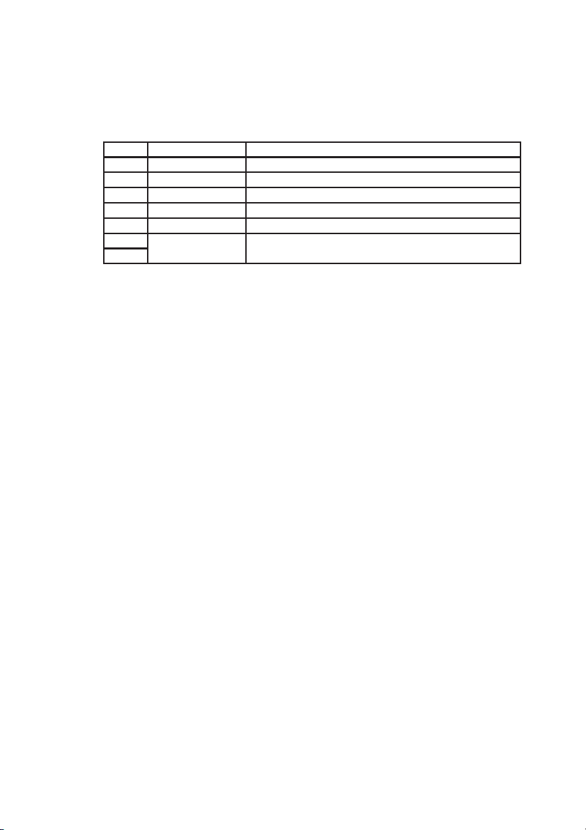
2.4 INTERFACE
The most common access to the parameters of the card is done using the drive keypad.
From the OPTIONS\Option2\Menu menu, the parameters of the option can be read/
written, status and database commands can be executed.
DRIVE
PLC
FIELD BUS card
DNET card
DGFC
FIELDBUS
card
BUSDNET
SLINK3 SLINK3
RS485RS485
Figure 2.4.1: DGF Communication
A second possibility is the use of the DGF serial line, connecting it to a personal
computer and using a HIBS program. It is possible to execute read/write parameter
commands, supervision pages, to visualize the card parameters, execute status commands
or database load and save commands from/to disk. The serial line of the option uses SLINK3 protocol.
DGF parameters can be read or written also via the serial line of the drive on which it
is installed. Figure 2.4.1 shows the various connection and communication possibilities.
2.4.1 Drive keypad
The drive keypad can be used to control the functions of the DGF, and to modify the
DGF parameters.
T o enter the DGF Menu from the drive main menu, it is necessary to call the submenu
OPTION, then OPTION 2.
The “OPTIONS/OPTION2/OPT2” submenu contains the Enable/Disable option
command that enables or disables the DGF. This parameter is read only once at
power on. If modified, the new value is operative after the next power on.
In the “OPTION/OPTION2/MENU”, the DGF controls the keypad. DGF items are
displayed through the menus and submenus; you can move in the menu by pressing
UP (from the current item to the previous one) and DOWN (from the current item to
the next one). If you are not able to access OPTION2\MENU, this means that the DGF
is not recognized by the drive.
The current menu or submenu can be entered by pressing ENT (access to submenus)
and ESCAPE (return to the previous menu or submenu).
The structure of the various menus of the DGF is shown in the following diagram:
40
—————— Digital General Function Card ——————
Page 41

6KCV301DGF
MENU
OPT2
VIEW PARAMETER
VIEW DATA BASE
STATUS DGFC
RESET ALARM
IDLE TO READY
READY TO RUN
STATUS TO IDLE
ARCHIVES
CHECK ALL DB
SAVE ALL DB
LOAD ALL DB
INIT ALL DB
CHECK PARAMETERS
SAVE PARAMETERS
LOAD PARAMETERS
DEFAULT PARAMETERS
CHECK BRICKS
SAVE BRICKS
LOAD BRICKS
INIT BRICKS
SPECIAL FUNCTIONS
PASSWORD
d0028
MENU VIEW PARAMETER:
In this submenu all parameters of the card are displayed. If the parameters can be
changed and the status logic permits it, they can be written.
To access this menu (from OPTION/OPTION2/MENU) move among menus by pressing
UP and DOWN until you find:
opt: DGFC
view parameters
k001
then press enter(ENT).
You are now in the view parameters DGF menu.
Once enter is pressed the following information will be displayed:
1DgfcBrk386
1.000 ver
k002
The first line shows a number (this is the IPA of parameter) and a string (this is the
DESCRIPTOR).
The second line shows the actual value of the parameter and the measure unit, if any. If
the parameter type is defined as hexadecimal, the parameter is displayed in hexadecimal
notation. You can move from a parameter to another by pressing UP and DOWN .
For example, by pressing DOWN , a new parameter will be displayed:
—————— Digital General Function Card ——————
41
Page 42

GEI-100430
749 ivar 49
0
_______
k003
If you want know some of the parameter attributes press enter(ENT).
749 ivar 49
par 0
k004
By pressing UP and DOWN you can display some attributes of the parameter.
Available attributes are:
par
min
max
att
proc
def
type
ipa
k005
Refer to the DBASE description for the meaning of these attributes.
T wo of these fields are also writable. These fields are:
par
ipa
k006
If you change the par attribute you change the value of the parameter.
If you change the ipa attribute you can move directly to a new parameter, without the
use of UP and DOWN (this can be faster).
To enter a new value, you must select the desired attribute, then press enter(ENT). If
the attribute is writable the rightmost digit starts blinking. You can:
1) change the value of the blinking digit by pressing plus(+) and minus(-) keys. The
available characters you can enter are:
IF THE VALUE YOU WANT TO
ENTER IS IN DECIMAL NOTATION
‘0’ to ‘9’ ‘0’ to ‘9’
e ‘A’ to ‘F’
.
-
space
IF THE VALUE YOU WANT TO
ENTER IS IN HEXADECIMAL
NOTATION
d0290g
As you can see, if the number is in decimal notation you can enter even the exponential
notation.
42
—————— Digital General Function Card ——————
Page 43

6KCV301DGF
For example, you can enter :
7 e-1 for 0.700.
2) change the digit you want to modify, by pressing UP and DOWN . The blinking
digit changes its position
3) enter the value you have written, by pressing enter(ENT)
4) abort the edit, by pressing cancel(CANC)
IMPORTANT: after the value is entered, the value is displayed “as best is possible”.
So, it may happen, that the value entered in exponential notation seems not to be
“accepted” by the DGF, for example when it has too many decimals to fit the normal
notation of the keypad. For example, if you enter:
1.0001 e-10
this will be displayed as:
1.000 e-10
while the real value is the value entered. Note also that the value displayed may be
rounded. For example, if you enter:
1.0005 e-10
this will be displayed as:
1.001 e-10
while the real value is the value entered. To exit this menu press cancel(CANC) until
you find:
opt: DGFC
view parameters
k001
MENU STATUS DGF:
In this menu the current status of the card is displayed. It can also be modified. To
access this menu(from
OPTION/OPTION2/MENU) move among menus by pressing UP and DOWN until
you find:
opt: DGFC
status DGFC
k007
then press enter(ENT).
Y ou are now in the status DGF menu. Once enter is pressed the following information
will be displayed:
status IDLE
reset alarm
k008
The first line shows the actual status of the DGF.
The second line shows the actual transition you can perform by pressing enter(ENT).
By pressing UP and DOWN you can change the possible transitions:
The available transitions are:
—————— Digital General Function Card ——————
43
Page 44

GEI-100430
reset alarm
status to IDLE
READY to RUN
IDLE to READY
k010
If you want to perform one of the above transitions, display it and then press enter(ENT).
If it is possible to perform the selected transition, the new status will be displayed in
the first line of the menu.
To return to the main menu of the DGF press cancel (CANC) until you find:
opt: DGFC
status DGFC
k007
MENU ARCHIVES:
From this menu it is possible to verify, save, load, or initialize the whole database
(Application program + Parameters), only parameters, or only bricks.
NOTE: These commands can be executed only in IDLE condition.
To access this menu (from OPTION/OPTION2/MENU) move among menus by pressing
UP and DOWN until you find:
opt: DGFC
archives
k012
then press enter(ENT). You are now in archives menu.
Once enter is pressed the following information will be displayed:
archives
check all DB
k013
The first line never changes.
The second line shows the possible action you can choose. Available actions are:
44
check all DB checks all DB
action meaning
save all DB saves in flash all DB
load all DB loads from flash all DB
init all DB initializes all DB
check parameter checks parameters
save parameter saves parameters in flash
load parameter loads parameters from flash
default parameter loads default parameters
check bricks checks bricks
save bricks saves bricks in flash
load bricks loads bricks from flash
init bricks initializes bricks in RAM
d0300g
—————— Digital General Function Card ——————
Page 45

6KCV301DGF
Choose the desired action, then press enter(ENT).
Once enter is pressed the following information will be displayed:
init briks
are you sure ?
k015
The first line displays the action you have chosen.
The second line(blinking) asks you whether are you sure or not.
Press enter(ENT) to confirm the operation, press cancel (CANC) to abort the operation.
This submenu is very useful to save the parameters from the keypad, without using the
PC. If you want to save the parameters, place the DGF in IDLE status and then select
the “save parameter” action of this submenu.
To return to the main menu of the DGF press cancel (CANC) until you find:
opt: DGFC
archives
k012
MENU SPECIAL FUNCTION:
This menu contains only the input of a password. If the password is enabled, it is
possible to change some of the attributes that are not changeable in the “view parameter”
menu. To access this menu (from OPTION/OPTION2/MENU) move among menus by
pressing UP and DOWN until you find:
opt: DGFC
special funct.
k016
then press enter (ENT). You are now in special function menu.
Once enter is pressed the following information will be displayed:
special funct.
password
k017
The first line displays the name of menu.
The second line display the name of the submenu. Since there are no other submenus,
press cancel to return to the main menu, or enter to enter the password.
If you press enter the following information will be displayed:
password
k018
At this point you must enter the password. The correct password is:
UP
DOWN
CANC
ENT
During the input an asterisk will be displayed for each key pressed.
password
**
k019
—————— Digital General Function Card ——————
45
Page 46

GEI-100430
If you want to abort the input press CANC until an error message appears on the
display. If the password is entered correctly the following information will be displayed:
special funct.
password
k017
If the password is not entered correctly the following information will blink:
ERROR: 9
k021
If this message appears, press any key to continue.
To return to the main menu of the DGF press cancel (CANC) until you find:
opt: DGFC
archives
k012
If the password is entered correctly, you will be able now to go in the “view parameter”
menu and change all the following attributes:
attribute
par YES YES
min NO YES
max NO YES
att NO NO
proc NO YES
def NO NO
type NO NO
ipa YES YES
changeable without
password
changeable with
password
d0310g
ERROR MANAGEMENT:
When you are using the keypad to enter a value, you can introduce one or more errors.
In this case the following information will blink:
ERROR: 9
k021
If this message appears, look at the error table for specific information.
T o recover from this error press any key and retry the input.
46
—————— Digital General Function Card ——————
Page 47

6KCV301DGF
2.4.2 DGF Serial line
Using the DGF serial line RS485 port it is possible to communicate with an external
device (e.g. PC) by using S-LINK 3 protocol.
The DGF uses the following S-LINK3 commands:
1) “Read typed parameter” with S=0, fixed length (only one parameter per command)
and “DATA TYPE” included between 2 and 8.
2) “Write typed parameter” with S=0, fixed length (only one parameter per command)
and “DATA TYPE” included between 2 and 8.
For more information see the S-LINK3 manual, GEI-100342.
2.4.2.1 HIBS
2.4.3 DRIVE SERIAL LINE
By using the serial line of the drive RS485 port, the DGF can be accessed as it is
directly connected to its serial line.
The HIBS program can be used in the same way. The only thing you must remember is
to choose the appropriate protocol and address.
For more information refer to SLINK3 Communications Protocol manual.
2.4.4 DeviceNet
The DGF and drive parameters, IVARs and FVARs can be read and written via
DeviceNet.
For more information refer to DeviceNet manual .
2.4.5 Serial bus interface (SBI)
DGF parameters can be read and written via an optional communication card (Interbus,
Profibus, etc).
For more information see the specific bus documentation.
—————— Digital General Function Card ——————
47
Page 48

GEI-100430
2.5 DRIVE PARAMETERS
All the drive parameters are accessed using the DPRAM communications of the DGF .
With the high priority synchronous communications (high speed) it is possible to
exchange only a subset of the drive parameters. This subset is listed in the drive manual
in the “LIST OF HIGH PRIORITY PARAMETERS”. This list includes the main
regulation parameters (speed, current ref..), encoder parameters and pad parameters.
Limits of these parameters are not tested on the drive so the limits must be controlled
in the DGF program. Please note that the measure units of high priority parameters are
different from the units of low priority parameters. For detailed information see the
drive manual.
Encoder parameters allow the DGF to read the Encoder position, Speed and Last time
of the two encoders of the drive regulation.
The Pad parameter may be programmed on the drive to read the three analog inputs or
write the analog outputs of the TBO. Pad parameters are also used for fast communication
between a bus card (e.g. Profibus) and a DGF.
With the low priority asynchronous communications it is possible to exchange a
larger subset of parameters. The digital I/O of the two TBO cards can be exchanged by
using pad parameters A and B.
With manual communication it is possible to exchange all the drive parameters.
48
—————— Digital General Function Card ——————
Page 49
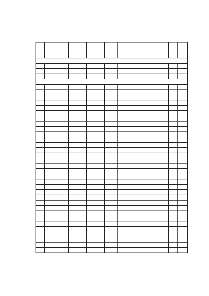
2.6 PARAMETER DESCRIPTION
2.6.1 List of parameters
6KCV301DGF
IPA Descriptor
1 Sgf briks ver. READ IDLE FLOAT 0 65000 N/A 1
2 identif - WIDLE IDLE FLOAT 0 65000 0 3 act addr - READ IDLE UCHAR 0 127 1 3
100 ie syn 0 - WIDLE IDLE UINT 0 65000 0 100
101 ie syn 1 - WIDLE IDLE UINT 0 65000 0 100
102 ie syn 2 - WIDLE IDLE UINT 0 65000 0 100
103 ie syn 3 - WIDLE IDLE UINT 0 65000 0 100
104 ie syn 4 - WIDLE IDLE UINT 0 65000 0 100
110 ei syn 0 - WIDLE IDLE UINT 0 65000 0 110
111 ei syn 1 - WIDLE IDLE UINT 0 65000 0 110
112 ei syn 2 - WIDLE IDLE UINT 0 65000 0 110
113 ei syn 3 - WIDLE IDLE UINT 0 65000 0 110
114 ei syn 4 - WIDLE IDLE UINT 0 65000 0 110
120 ie asyn 0 - WIDLE IDLE UINT 0 65000 0 120
121 ie asyn 1 - WIDLE IDLE UINT 0 65000 0 120
122 ie asyn 2 - WIDLE IDLE UINT 0 65000 0 120
123 ie asyn 3 - WIDLE IDLE UINT 0 65000 0 120
124 ie asyn 4 - WIDLE IDLE UINT 0 65000 0 120
125 ie asyn 5 - WIDLE IDLE UINT 0 65000 0 120
126 ie asyn 6 - WIDLE IDLE UINT 0 65000 0 120
127 ie asyn 7 - WIDLE IDLE UINT 0 65000 0 120
128 ie asyn 8 - WIDLE IDLE UINT 0 65000 0 120
129 ie asyn 9 - WIDLE IDLE UINT 0 65000 0 120
140 ei asyn 0 - WIDLE IDLE UINT 0 65000 0 140
141 ei asyn 1 - WIDLE IDLE UINT 0 65000 0 140
142 ei asyn 2 - WIDLE IDLE UINT 0 65000 0 140
143 ei asyn 3 - WIDLE IDLE UINT 0 65000 0 140
144 ei asyn 4 - WIDLE IDLE UINT 0 65000 0 140
145 ei asyn 5 - WIDLE IDLE UINT 0 65000 0 140
146 ei asyn 6 - WIDLE IDLE UINT 0 65000 0 140
147 ei asyn 7 - WIDLE IDLE UINT 0 65000 0 140
148 ei asyn 8 - WIDLE IDLE UINT 0 65000 0 140
149 ei asyn 9 - WIDLE IDLE UINT 0 65000 0 140
297 ie save - WIDLE IDLE HULINT 0 FFFFFFFFH 0 299 en dpram (2) - WIDLE IDLE UINT 0 1 1 -
Measure
unit
Status of
access
Memo Type Min Max Def. Proc
IDENTIFIERS
DP-RAM
dpar1
—————— Digital General Function Card ——————
49
Page 50

GEI-100430
IPA Descriptor
300 cw cpu - WIDLE IDLE HULINT 0 FFFFFFFFH 7 301 id card 1 - WIDLE IDLE UINT 0 100 0 302 cw card 1 - WIDLE IDLE HULINT 0 FFFFFFFFH 0 303 id card 2 - WIDLE IDLE UINT 0 100 0 304 cw card 2 - WIDLE IDLE HULINT 0 FFFFFFFFH 0 305 id card 3 - WIDLE IDLE UINT 0 100 0 306 cw card 3 - WIDLE IDLE HULINT 0 FFFFFFFFH 0 307 id card 4 - WIDLE IDLE UINT 0 100 0 308 cw card 4 - WIDLE IDLE HULINT 0 FFFFFFFFH 0 -
350 dgf mode (2) - WIDLE IDLE INT 0 10 2 351 WPD status - READ OFF INT 0 1 0 351
400 DNet enable - WIDLE IDLE UINT 0 1 0 401 DNet status - WRUN OFF UINT 0 65535 0 402 DNet StAux - WRUN OFF UINT 0 65535 0 403 DNetStUser - WRUN OFF UINT 0 65535 0 404 DNetMacId - WIDLE RUN UINT 0 63 63 405 DNetBaud - WIDLE RUN UINT 0 2 0 406 DNSvrCnxn - WIDLE IDLE UINT 0 10 3 407 DNetMsg - WRUN IDLE UINT 0 5 0 420 DNetI/OEpr mSec WIDLE IDLE UINT 0 16250 0 421 DNSlaveLow - WIDLE IDLE HULINT 0 FFFFFFFFH 0 422 DNSlaveHig - WIDLE IDLE HULINT 0 FFFFFFFFH 0 430 DN#RxPLC - WIDLE IDLE UINT 1 20 1 431 DN#TxPLC - WIDLE IDLE UINT 0 20 0 -
500 period mode - WIDLE IDLE UINT 0 2 1 501 period time mSec WIDLE IDLE UINT 1 50 1 501
502 period rea mSec READ OFF UINT 0 65000 0 503 ab. Resall - WALL IDLE UINT 0 2 1 503
504 ab. RUN - WIDLE IDLE UINT 0 2 1 504
506 wstato - WALL OFF UCHAR 0 10 2 506
507 en. Last (1) - WIDLE IDLE UINT 0 1 1 508 auto run - WIDLE IDLE UINT 0 1 0 509 sbord Syn - WRUN OFF UINT 0 65535 0 510 sbord.asyn - WRUN OFF UINT 0 65535 0 511 address - WIDLE OFF UCHAR 0 127 1 511
512 Real time mSec WRUN OFF UINT 0 65535 0 555 cmd remote - WALL OFF UINT 0 65535 0 555
Measure
unit
Status of
access
Memo Type Min Max Def. Proc
I/O CONFIGURATION
MODE SELECTION
DEVICENET
SYSTEM
dpar2
50
—————— Digital General Function Card ——————
Page 51

6KCV301DGF
IPA Descriptor
1000 fvar - WRUN IDLE FLOAT -3.4E+38 3.4E+38 0 1199 fvar - WRUN IDLE FLOAT -3.4E+38 3.4E+38 0 1200 ivar - WRUN IDLE INT 0 32767 0 1299 ivar - WRUN IDLE INT 0 32767 0 2000 num - WRUN IDLE HULINT - - 0 2099 num - WRUN IDLE UINT - - 0 -
Measure
unit
Status of
access
Memo Type Min Max Def. Proc
PROGRAMMABLE
dpar3
N/A: not applicable
(1) this parameter is reserved
(2) this parameter is active only at power-on
Status of access:
WIDLE -> write only in IDLE status
WREADY -> write in IDLE and READY status
WRUN -> write in IDLE, READY and RUN status
WALL -> write in all status, including ALERT
READ -> read only parameter
Memo:
IDLE -> store the entire record in flash in IDLE state
RUN -> store the attribute in flash in IDLE status and the value in EEPROM in
RUN status
ATTR -> store only the attribute in flash in IDLE status.
OFF -> do not store anything
2.6.2 Description of parameters
2.6.2.1 Identification parameters
[1] VERSION Base Software version DGF-BRICKS
[2] IDENTIF Identification, reserved for name and version
of the BRICKS application
[3] ACT-ADDR Address for S-LINK3 cards. The address is
written through parameter 511 and then
automatically copied and stored in parameter
3. The ACT-ADDR cannot be saved in a
parameter file.
—————— Digital General Function Card ——————
51
Page 52

GEI-100430
2.6.2.2 DPRAM parameters
[100...104] IE SYN 0...4 Synchronous communication (high priority)
between the DGF and drive.
Contains the drive parameter number written on the drive (0 = no parameters)
[110...114] EI SYN 0...4 Synchronous communication between the drive
and DGF.
Contains the drive parameter number read from the drive (0 = no parameters)
[120...129] IE ASYN 0...9 Asynchronous communication (low priority)
between the DGF and drive.
Contains the drive parameter number written by the DGF (0 = no parameters)
[140...149] EI ASYN 0...9 Asynchronous communication between the
drive and DGF.
Contains the drive parameter number read by the DGF (0 = no parameters)
[297] EI _SAVE
FORMAT
WORD H WORD L
31 31 24 23 22 21 20 19 18 17 16 4 3 2 1 0
IE-ASYN IE-SYN
When the DGF is in “Run” status, the automatic synchronous
and asynchronous communications cyclically write several
drive parameters. When the DGF is not in “Run” status, the
drive parameters controlled by automatic communications are
not cyclically written.
The bits of parameter 297 allow or inhibit modification of the
drive parameter value, when the DGF is not in “Run” status.
The first 5 bits of the low word are associated respectively
with the 5 synchronous communications. The first 10 bits of
the high word are associated respectively with the 10
asynchronous communications.
297 [n] = 0 drive parameter is forced to zero
297 [n] = 1 drive parameter keeps the last value calculated by DGF
where n: 0...31 is the bit number of the double word.
As default value, the 297 parameter is set to zero.
52
—————— Digital General Function Card ——————
Page 53

6KCV301DGF
[299] EN DPRAM Disables the DPRAM communication structure
when it is equal to “0”.
If it is changed, it has an effect only after a hardware reset.
2.6.2.3 I/O configuration
[300] CW_CPU Control word of CPU
Enables the use of some hardware resources of the DGF
[301, 303, 305, 307] ID_CARD Cards 1, 2, 3, 4 identifier
Identifies the DGF I/O optional card used (not yet available)
[302, 304, 306, 308] CW_CARD Control word card 1, 2, 3, 4
Each card has a control word associated (not yet available)
2.6.2.4 Mode configuration
[350] DGF_MODE It sets the mode of the DGF
Permissible values are the following:
0 = Only BRICKS Enabled
1 = BRICKS and WIN+DRIVE Enabled
2 = Only WIN+DRIVE Enabled
10 = Only DeviceNet enabled
[351] WPD STATUS Status of WIN+DRIVE block
Permissible values are the following:
0 = WIN+DRIVE block disabled
1 = WIN+DRIVE block enabled
2.6.2.5 Can controller parameters (DeviceNet)
The range of indexes of the parameters dedicated to DeviceNet is from 400 to 499.
For a detailed description, see DeviceNet manual.
2.6.2.6 System parameters
These are parameters that modify the behavior of the system, e.g.. on sampling period
or status logic and define the various modes at which the operation status of the option
can be changed.
[500] PERIOD_MODE Working operation mode; possible values are:
1 = synchronous with drive
2 = asynchronous (DGF internal Timer)
Any other value can crash the DGF .
—————— Digital General Function Card ——————
53
Page 54

GEI-100430
[501] PERIOD_TIM Period scan time in msec.
With synchronous operation, a multiple of 2 will be accepted.
[502] PERIOD_REA Period real scan time in msec (example 10 = 10
msec). This is the period that has been accepted
by the DGF.
With PERIOD_MODE at 2 this is equal to
PERIOD_TIM
With PERIOD_MODE at 1 this is a multiple of
2 of PERIOD_TIM(rounded up)
[503] AB_RESALL Enable reset alarms
This parameter selects the source that determines the end of the alert status (transition
Alert-Ready). Possible values are the following:
0 = transition enabled via DGF serial line S-LINK3,
drive keypad or field bus
1 = transition through drive alarm reset
2 = transition via digital input of the optional I/O
card. In case 0, the transition is performed by
writing the parameter WSTATO[506]. In case
1, the DGF exits from the Alert status
automatically when the alarm status on the drive
is reset. In case 2 the DGF exits from the Alert
status by using the digital input of the optional
I/O card.
[504] AB_RUN T ransitions READY - RUN and RUN - READY
It determines the conditions for READ Y-RUN and RUN - READY transition.
Possible values are:
0 = only the transition via serial line S-LINK3 or
field bus is active
1 = only the automatic transition with drive enable/
disable is active
2 = transition via digital input of I/O optional card
(see also “AUTO-RUN” [508]).
[506] WSTATO Status of the DGF
This parameter displays the status of the card. If it is written, it allows changing the
DGF status.
54
—————— Digital General Function Card ——————
Page 55

6KCV301DGF
Possible values are :
VALUE STATUS
0 Reserved (NULL (#) )
1 Reserved (SINCRO (#) )
2 IDLE
3 READY
4 Reserved (SINGLE (#) )
5 RUN
7 ALERT
8 (*) RESALL (*)
(*) By writing this value an alarm reset will be performed
(#) Special status, not to be used (reserved only to factory)
d0340g
Note that the transitions Ready - Run and the alarm reset occur via AB_RUN and
AB_RESALL parameters. Therefore, this parameter can be used to write the new
status only if the serial communication, keypad or field bus is enabled (AB_RUN
and/or AB_RESALL equal to 0).
[507] EN_LAST Reserved
[508] AUTO_RUN Automatic RUN status
When the card is supplied power, AUTO_RUN controls the automatic
transition
READY-RUN, if the necessary operating conditions are satisfied.
The transition depends on the “AB_RUN” parameter setting.
The possible configurations are as follows:
AUTO_RUN = 0 : the automatic transition is not carried out.
AUTO_RUN = 1 AB_RUN = 0 : the transition READY-RUN is
carried out automatically one time. To set the card in READY again,
a command via serial line SLINK3, keypad or field bus is necessary
AUTO_RUN = 1 AB_RUN = 1 : the card remains in READY
condition until the drive is disabled.
AUTO_RUN = 1 AB_RUN = 2 : the card remains in READY
condition until the appropriate digital input of the optional I/O card
is set to high level
AUTO_RUN =2 ABI_RUN=1
The control reaches directly the run condition and ir remain here in
spite of possible ALARM condition of the drive.
For each of these configurations, it is necessary that initial conditions
move the card into the READY status. If this does not occur, the
card remains in the IDLE state.
[509] SBORD SYN Number of times the period exceeds
PERIOD_TIM
—————— Digital General Function Card ——————
55
Page 56

GEI-100430
When the period is activated by the drive(PERIOD_MODE=1) this
parameter indicates the number of times that the synchronous period
takes longer than PERIOD_TIM. This parameter must be always 0.
[510] SBORD ASYN Number of times the period exceeds
PERIOD_TIM
When the period is activated by the DGF(PERIOD_MODE=2) this
parameter indicates the number of times that the asynchronous period
takes longer than PERIOD_TIM. This parameter must be always 0.
[511] ADDRESS Address of the card for SLINK 3
It is used to write the Slink3 address of the DGF . If written, the value
is copied and saved in parameter [3] “ACT-ADDR”.
Note: the address of the serial line cannot be saved in a parameter
file.
[512] Real time Maximum real period time
This is the maximum number of milliseconds taken by the user
program to execute the period.
[555] CMD_REMOTE Remote command
It allows the receiving of DBASE commands via the serial line of
the drive or via a communication card. Possible commands:
56
CODE COMMAND
310 Save Dbase parameters
311 Load Dbase parameters
312 Check Dbase parameters
313 Init. Dbase parameters
d0350g
—————— Digital General Function Card ——————
Page 57

6KCV301DGF
2.7 HOW TO CONFIGURE THE DGF
2.7.1 Which method to use
In order to configure the DGF you must choose the appropriate method. There are
several ways to access the DGF:
1) through the DRIVE KEYPAD;
2) through the serial line of the DGF, in conjunction with a PC running the HIBS or
WHIB programs;
3) through the serial line of the Drive, in conjunction with a PC running the HIBS or
WHIB programs ;
4) through a fieldbus.
We strongly recommend the use of the HIBS or WHIB programs. This is faster than
the drive keypad and fieldbus, allowing access to all resources of the DGF.
2.7.2 First configuration of DGF
The following guide is intended as an aid to configure the DGF for the first time, when
the DGF has the default parameters, or when you want to change some basic parameters.
When you access parameters of the DGF always remember the “status of access” of
each parameter. Many of the parameters described later are accessible only in IDLE
state. This will require you to transition the DGF to the IDLE state before starting.
2.7.3 Mode configuration
There are 2 modes to operate the DGF:
1) execute a W in+Drive program;
2) execute only DeviceNet software.
The mode is selected by parameter DGFC_MODE(350). Parameter
WPD_STATUS(351) monitors the status of WPD enable flag.
Note that when you choose “only DeviceNet” the card acts as a fieldbus interface,
losing the ability to be programmed. You can use DeviceNet in a Win+Drive program
by choosing the first mode. See DeviceNet manual for additional information.
2.7.4 Basic transition
Basic transitions are the transitions from/to RUN status and the exit from ALERT
status. These transitions can be configured to be executed from 3 different sources:
1) from the serial line, fieldbus or drive keypad (by writing parameter WSTATO,
506);
2) through the corresponding transition of the drive;
3) through a digital input of a DGF optional card.
—————— Digital General Function Card ——————
57
Page 58

GEI-100430
There is also the possibility to transition the DGF directly to RUN status at power-on.
For the READY to RUN transition the parameter to set is AB_RUN(504). T o transition
the card into RUN status at power on set the parameter AUTO_RUN(508). T o exit the
ALARM status(transition ALARM to READY) set the AB_RESALL(503) parameter.
Depending on your system requirements, configure these three parameters in the
appropriate way.
2.7.5 Working mode
The working mode of the DGF determines how and when the DGF starts the execution
of the user program or of the DeviceNet interface, when this is executed alone (from
now they are referred to as “period”).
You can configure:
1) how often to execute the period in the DGF;
2) whether the period can be started by the drive or cyclically by the DGF.
To set the source of the beginning of the period use parameter PERIODMODE(500).
Normal condition requires that the DGF starts the period with the drive.
To set how often the period will be executed, set the parameter PERIOD_TIM(501).
This must be a multiple of 2. You can read the effective value (a multiple of 2) in
parameter PERIOD_REA(502). To know the length of the maximum period, read
parameter REAL_TIME(512).
IMPORTANT: since the period has the highest execution priority internally to
the DGF, you must be sure to allow enough time for the
remaining services of the DGF (serial, fieldbus, dbase,
malfunction check, ...). For this reason the maximum value of
REAL_TIME must not exceed 2/3 of the value of
PERIOD_REA.
Depending on the period you have written, the period can take a longer or a shorter
time to be executed. This time is longer when you use complex blocks or many blocks
inside your period. So you must always set the appropriate period time in order to
optimize the use of the DGF.
To set the appropriate period time, you can do the following:
1) Set PERIOD_TIM to 50msec (this is how often the period is started, for now
every 50msec)
2) Load the period and execute it
3) Look at PERIOD_REA after a certain time (this is the maximum time the period
took to be executed)
4) Set PERIOD_TIM to PERIOD_REA * 1.5, multiple of 2 (this is how often the
period is started, now with the optimized value)
58
—————— Digital General Function Card ——————
Page 59

6KCV301DGF
2.7.6 Serial address
The DGF supports the Slink3 and Slink4 multi-point protocols. The DGF can
communicate via its own serial line as well by the drive serial line. When the DGF
communicates through its own serial line you must address it by its own address,
parameter ADDRESS(511) . When the DGF communicates through the drive serial
line you must address it by drive address, setting the option field at 2. When you link
2 or more nodes together you must specify different addresses for each node. Y ou must
set the ADDRESS parameter (511) to the desired address. It will be copied into parameter
ACT_ADDR(3).
2.7.7 DP-RAM
Y ou must configure the interface with the drive. Parameter EN_DPRAM(299) enables/
disables the DPRAM. If enabled, you must configure the parameters of the drive you
want to modify. Parameters 100 to 149 specify the direction of the parameter (IE means
from the DGF to drive, EI means from the drive to DGF) and their priority (SYN
means high priority, ASYN means low priority). You must set the index of the drive
parameter you want to access. The drive parameter will be accessed by the period.
When the period is not executed (the DGF is in READY status) the value of the written
parameters are set to 0. Y ou can avoid this by setting the appropriate bits in the IE_SAVE
parameter (297). Usually these parameters are not set through DBASE but with the
programming tools.
2.7.8 I/O configuration
It is possible an hardware configuration directly by the DGF. This includes DGF
LEDs H1, H2, H3 and H4 and some test points and all the possible I/O cards.
To configure on-board DGF hardware use the parameter CW_CPU(300). For normal
operation set this parameter to the default value. If you need one or more of the resources
of the DGF reset the corresponding bit in the in CW_CPU and use then with the
appropriate brick.
To configure the additional hardware there are 4 sets of parameters: ID_CARD 1,2,3
and 4(301, 303, 305, 307) and the corresponding CW_CARD 1,2,3 and 4 (302, 304,
306, 308). Y ou must set the identifier of the additional card in the ID_CARD parameter
and the configuration of the hardware in CW_CARD. Refer to the applicable card
documentation for more information.
—————— Digital General Function Card ——————
59
Page 60

6KCV301DGF GEI-100430 04/99
Rev. 0.1 / 4.5.99
1S5G20
We bring good things to life.
GEI-100430 Rev. 0.0 (04/99)
GE Industrial Systems
Internet Address: http://www.ge.com
 Loading...