

Page 1
6KCV3oOWPD
Win+Drive
GE Motors & Industrial Systems
Page 2

GEL100340
These instructions do not purport to cover all details or variations in equipment, nor to provide every
possible contingency to be met during installation, operation, and maintenance. If further information is
desired or if particular problems arise that are not covered
sufficiently
for the purchaser’s purpose, the
matter should be referred to GE Motors & Industrial Systems.This document contains proprietary information of General Electric Company, USA and is furnished to its customer solely to assist that customer
in the installation, testing, operation, and/or maintenance of the equipment described. This document
shah not be reproduced in whole or in part nor shah its contents be disclosed to any third party without
the written approval of GE Motors & Industrial Systems.
0
1997 by General Electric Company, USA. All rights reserved.
Page 3

Table of Contents
Wintllrive
1.
Introduction
1.1
About
1.2
Document Conventions ........................................................................................................................
1.3
Installation
1.3.1 System requirements ...................................................................................................................
1.3.2
2.
Developing a
2.1What
2.2 Introducing
2.2.1
2.2.2 The Code Generation ..................................................................................................................
2.2.3
2.2.4
2.3 The Development Process
3.
FastTrack to
3.1
Menu Summaries .................................................................................................................................
3.1.1 Managing
3.1.2 Editing schematics
3.1.3 Changing the view of the schematics
3.1.4
3.15 Working with compound blocks
3.1.6 Debugging projects
3.1.7 Tools ............................................................................................................................................
3.1.8 Options ........................................................................................................................................
3.1.9 Window operations
3.1.10 Help
4.
The Win+Drive
4.1 Starting Win+Drive
4.1.1 Starting from Windows
4.1.2 Starting from Windows 3.1
4.2 Opening
4.2.1 Creating
4.2.2 Opening an
4.3
Saving
4.4
The
4.4.1 Menus .........................................................................................................................................
4.4.2 Toolbar.. ......................................................................................................................................
4.4.3 Block Selection Bar...................................................................................................................
4.4.4 Statusbar
4.4.5 Windows ....................................................................................................................................
4.4.6 Schematics Windows.................................................................................................................
4.4.7 Output Window
4.4.8 Monitor Windows ......................................................................................................................
4.4.9 Trace Windows
4.4.10 Getting Help ............................................................................................................................
4.5
Exiting
..................................................................................................................................................
Manual ................................................................................................................................
this
of Win+Drive ....................................................................................................................
Installation
The
Win+Drive Application ..........................................................................................................
Win+Drive?. ............................................................................................................................
is
the Tools ...........................................................................................................................
The
Schematic Editor ..................................................................................................................
The Simulator
The
Library Editor.......................................................................................................................
Win+Drive ..............................................................................................................................
Inserting
menu
Design Environment..
Projects ................................................................................................................................
a Project .................................................................................................................................
Win+Drive
Win+Drive .............................................................................................................................
Sequence ...........................................................................................................
..............................................................................................................................
Files and Printing
into
items
.................................................................................................................................
............................................................................................................................
a new project...............................................................................................................
existing
Screen Layout ...........................................................................................................
....................................................................................................................................
1
1
2
2
2
2
3
3
3
3
3
3
3
....................................................................................................................
.......................................................................................................
.......................................................................................................................
..........................................................................................
the schematics .............................................................................................
..................................................................................................
.....................................................................................................................
......................................................................................................................
.......................................................................................................
95
........................................................................................................
.......................................................................................................
project..
.........................................................................................................................
..........................................................................................................................
.....................................................................................................
4
5
5
5
6
6
7
7
8
8
8
9
9
10
10
10
10
10
10
10
10
11
11
11
12
12
13
13
14
15
15
16
16
i
Page 4

GEL100340
5.
Creating Software Schematics
5.1 Placing Software Blocks
....................................................................................................................
....................................................................................................................
5.1.1 Toolbar Placing Blocks by Drag&Drop from the Block
5.1.2
Placing
5.2 Connecting
Blocks
Software Blocks
5.3 Placing Text and Labels
5.3-l Placing a Text
5.3.2 Placing a Label
5.3.3
Modifying
5.3.4 Moving Texts or Labels
5.4 Editing the Ports of Blocks
5.4.1
Opening the Ports Editor Dialog
54.2 Setting the Port Connection
5.4.3 Setting the Port Attributes
5.5
Editing
Block Parameters
5.6 Changing the View
5.6.1
Positioning
56.2
Changing the Zoom factor
using
the Insert Menu
..............................................................................................................
.....................................................................................................................
............................................................................................................................
..........................................................................................................................
the Text ....................................................................................................................
.............................................................................................................
................................................................................................................
.......................................................................................................
.........................................................................................................
..................................................................................................................
of the Schematic
the View
................................................................................................................. 22
.........................................................................................................
5.6.3 Displaying additional Information on the Window
5.7
Modifying
Schematics
.......................................................................................................................
5.7.1 Selecting blocks and lines .........................................................................................................
5.7.2 Moving selected items
and
5.7.3 Copying
5.7.4
Resizing
5.7.5
Deleting items
5.7.6
Rotating
Moving via the
items
Blocks
5.8 Printing Schematics
5.8-l
Printing
5.8.2
Printing
5.8.3 Page Setup
in Window
in
Page Mode
for Printing
5.8.4 Setting Stamp Variables
5.8.5 Stamp
6.
ConnectiontoExternal
definition file format
Variables ...............................................................................................................
6.1 Variables and Logicals
6.2 The Variables
Dialog
6.3 The Logicals Dialog
...........................................................................................................................
...........................................................................................................................
...........................................................................................................................
...........................................................................................................................
...............................................................................................................
Clipboard ....................................................................................
.........................................................................................................................
.........................................................................................................
Mode
............................................................................................................... 26
.............................................................................................................
............................................................................................................ 28
......................................................................................................
....................................................................................................................... 30
...................................................................
6.4 Connecting Block Ports to Logicals
7.
Working
7.1
with
Hierachy and Compound
Creating and Opening Compound Blocks
7.1-l Creating a New Compound Block
7.1.2 Opening an existing Compound Block
7.1.3
Renaming
7.2 Block Inputs
Compound Block ..................................................................................................
a
and Outputs ...................................................................................................................
7.2.1 Placing Input and Output Ports
7.2.2 Renaming Ports
7.2.3
Changing
7.3 Updating and
Closing
7.4 Copying Compound Blocks
.........................................................................................................................
the Size of Ports ........................................................................................................
a Compound
...............................................................................................................
17
17
...........................................................
.......................................................................................
17
18
18
19
19
19
19
19
20
...............................................................................................
20
20
21
21
.................................................................................................
22
22
...................................................................
22
23
23
23
23
24
24
24
25
25
27
28
30
..................................................... 30
%.
31
..................................................................................................
Blocks .........................................................................................
.........................................................................................
............................................................................................
.....................................................................................
32
33
33
33
33
34
34
.................................................................................................
34
34
34
Block ........................................................................................
35
35
Page 5

WintDrive
7.5
7.6
Deleting
Using
Compound Blocks
Compound
Blocks ...................................................................................................................
...............................................................................................................
7.7 Export and ImportofCompound Blocks ...........................................................................................
7.7.1 ExportofCompound Blocks .....................................................................................................
of
7.7.2 Import
8.
Generating Programs ..................................................................................................................................
8.1
Generating
Compound Blocks .....................................................................................................
the Program
from
the Schematic .....................................................................................
8.2 Execution Order.................................................................................................................................
8.3
Compiling
8.4 Generating
the Program ......................................................................................................................
a Cross Reference ............................................................................................................
8.5 Editing the Block Icons ......................................................................................................................
8.6
Changing Build
9. Simulating Programs on the PC
9.1
Setting Probes ....................................................................................................................................
9.1.1 Setting Probes from the Edit menu
9.1.2 Setting Probes by the Context Sensitive Menu
9.2
Removing
9.3 Configuration of the Monitor Window
9.3.1 Monitor
9.3.2
Changing
9.3.3 Zoom within the Monitor Window
9.4 Configuration of the Trace Window
Options ....................................................................................................................
.................................................................................................................
...........................................................................................
.........................................................................
Probes ...............................................................................................................................
..............................................................................................
Configuration Dialog
the
List
of Probes
..................................................................................................
......................................................................................................
............................................................................................ 43
..................................................................................................
9.5 Running the Model ............................................................................................................................
9.5 .lDisplaying
9.5.2
Changing
10.
Changing
10.1
Settings
Scheme
Settings ...............................................................................................................................
10.2 General Settings
10.3 Changing the Colors
Values
Values
during Simulation
during Simulation
........................................................................................
..........................................................................................
of Win+Drive .............................................................................................................
...............................................................................................................................
........................................................................................................................
10.4 Setting up External Tools .................................................................................................................
35
36
36
36
37
39
39
39
40
40
40
40
41
41
41
41
42
42
43
43
43
44
44
44
45
45
46
46
47
Appendix A. Block Library
A.1
Block
library for
A.2 Introduction
DGFC 386
............................................................................................................................................
...................................................................................................
HELP ........................................................................................................
A.3 Block.. .....................................................................................................................................................
Group .......................................................................................................................................................
I/o
Group .................................................................................................................................................
Mathematics Group
Logical
Timer
Group ..........................................................................................................................................
Group .............................................................................................................................................
..................................................................................................................................
Delay Group .............................................................................................................................................
Function Group ........................................................................................................................................
Control Group ..........................................................................................................................................
Arithmetic
Variable Group
Generator
Group .....................................................................................................................................
.........................................................................................................................................
Group ......................................................................................................................................
49
49
49
49
50
50
50
5 1
51
51
52
52
53
53
53
I
. . .
111
Page 6

GEL100340
Input port..................................................................................................................................................
Parameter ................................................................................................................................................
output port
...............................................................................................................................................
A.4 Blocksinalphabetical order ....................................................................................................................
alarm ........................................................................................................................................................
and ............................................................................................................................................................
cfix
...........................................................................................................................................................
delay.........................................................................................................................................................
diamobs ....................................................................................................................................................
exe1 ..........................................................................................................................................................
exe2 ..........................................................................................................................................................
exe4 ..........................................................................................................................................................
exe8 ..........................................................................................................................................................
fabs ...........................................................................................................................................................
fadd ..........................................................................................................................................................
fass ...........................................................................................................................................................
fchs ...........................................................................................................................................................
fcnt
...........................................................................................................................................................
fcmp .........................................................................................................................................................
fdelay ........................................................................................................................................................
fdiv
...........................................................................................................................................................
feq ............................................................................................................................................................
ffd
.............................................................................................................................................................
ffjk
............................................................................................................................................................
fge
............................................................................................................................................................
fgt
.............................................................................................................................................................
fle
.............................................................................................................................................................
flt
..............................................................................................................................................................
fmod .........................................................................................................................................................
fmul
..........................................................................................................................................................
fmux
.........................................................................................................................................................
fne
.............................................................................................................................................................
fprc ...........................................................................................................................................................
fsel.................................................. ..........................................................................................................
fsub ...........................................................................................................................................................
fti
..............................................................................................................................................................
fun
............................................................................................................................................................
fvar
...........................................................................................................................................................
gsine
.........................................................................................................................................................
gsquare .....................................................................................................................................................
gtriangl
.....................................................................................................................................................
iabs ...........................................................................................................................................................
iadd.. .......................................................................................................................................................
iass..
........................................................................................................................................................
ichs .........................................................................................................................................................
icmp ........................................................................................................................................................
icnt
..........................................................................................................................................................
ida..
.........................................................................................................................................................
idelay
. . . . . . . . . . . . . . . . . . . . . . . . . . . . . . . . . . . . . . . . . . . . . . . . . . . . . . . . . . . . . . . . .
idiv
. . . . . . . . . . . . . .._.........................................................................................................................................
ids
. . . . . . . . . . . . . . . . . . . . . . . . . . . . . . . . . . . . . . . . . . . . . . . . . . . . . . . . . . . . . . . . . . . . . . . . . .
..-..................................................................................
..“.~.........~...........~............................~...............~..........
54
54
54
55
56
57
58
59
60
65
66
67
68
70
70
72
73
74
75
76
77
78
79
80
81
82
83
84
85
86
87
89
90
91
92
93
94
95
96
97
98
99
100
101
102
103
104
105
108
109
110
iv
Page 7

Wintllrive
ieq..
..........................................................................................................................................................
ige..
..........................................................................................................................................................
igt
............................................................................................................................................................
ile..
...........................................................................................................................................................
ilt
.............................................................................................................................................................
imod
........................................................................................................................................................
imul
.........................................................................................................................................................
imux
........................................................................................................................................................
ine
...........................................................................................................................................................
iprc .........................................................................................................................................................
isel
..........................................................................................................................................................
isub
.........................................................................................................................................................
itf
............................................................................................................................................................
ivar
.........................................................................................................................................................
.........................................................................................................................................................
land
lnot
.........................................................................................................................................................
lor
...........................................................................................................................................................
lxor
.........................................................................................................................................................
mfti
.........................................................................................................................................................
mitf
.........................................................................................................................................................
not ..........................................................................................................................................................
Oda
..........................................................................................................................................................
ods ..........................................................................................................................................................
Or
............................................................................................................................................................
.........................................................................................................................................................
Pwr
rbit
..........................................................................................................................................................
l-fix ..........................................................................................................................................................
speedobs .................................................................................................................................................
sqrt..........................................................................................................................................................
T .............................................................................................................................................................
tbd ..........................................................................................................................................................
tme
..........................................................................................................................................................
..........................................................................................................................................................
tpc ...........................................................................................................................................................
wbit
........................................................................................................................................................
wfix
........................................................................................................................................................
xor ..........................................................................................................................................................
112
113
114
115
116
117
118
119
121
122
123
124
125
126
127
128
129
130
131
132
133
134
137
139
140
141
142
144
146
147
148
150
152
154
155
156
158
V
Page 8

GEL100340
Appendix B Compound Library for
Compound Library for DGFC ...............................................................................................................
B. 1
B.2 Introduction
............................................................................................................................................
....................................................................................................
DGFC
Brief Library description ........................................................................................................................
How to use the Compound Library ........................................................................................................
Import compound block .........................................................................................................................
Input
port priority
Compound block
B.3
Library
contents .....................................................................................................................................
...................................................................................................................................
name ..........................................................................................................................
Analog Input ..........................................................................................................................................
AntiWindUp-PID
Cycle
Time
DC-MOTOR.
..................................................................................................................................
.............................................................................................................................................
.........................................................................................................................................
Deadband ...............................................................................................................................................
Digital-Input
First-Run..
FULL-RAMP
..........................................................................................................................................
..............................................................................................................................................
........................................................................................................................................
Integrator................................................................................................................................................
Lim-integrator
Limit..
.....................................................................................................................................................
Low-Pass-Filter
.......................................................................................................................................
....................................................................................................................................
Ramp ......................................................................................................................................................
Sign
........................................................................................................................................................
Time-Derivative
Time-Integrator..
Time-LimJnt
....................................................................................................................................
....................................................................................................................................
........................................................................................................................................
Ts ............................................................................................................................................................
Units-Converter
Glossary ................................................................................................................................................
B.4
.....................................................................................................................................
159
160
161
162
162
162
162
162
163
164
16.5
167
168
169
17 1
173
174
176
178
180
182
184
187
188
190
192
194
195
197
Page 9

WhOrive
List of Figures
Figure
2.3.1
Design
Flow .............................................................................................................................
Figure 4.4.2.1 Toolbar ....................................................................................................................................
Figure 4.4.3.1 Block Selection Bar ...............................................................................................................
Figure
Figure 4.4.5.1 Schematic Window
Figure
Figure
Figure
4.4.4.1 Status
Bar
...............................................................................................................................
................................................................................................................
4.4.7.1 Output window..
4.4.8.1
Monitor Window ....................................................................................................................
.....................................................................................................................
4.4.9.1 Trace Window ........................................................................................................................
Figure 5.1 Block ......................................................................................................................................
Figure
5.3.3.1
Change Text
Dialog
...............................................................................................................
Figure 5.4-l. 1 Ports Editor Dialog ................................................................................................................
Figure 5.5
Figure
Figure
Figure
Figure 5.8.2.1 Block Print List Dialog
Figure
Figure
Figure
Figure
Figure
Figure 6.3.1
Figure
Figure
Figure
.. 1
Block Parameter Dialog .........................................................................................................
5.7.6.1
Rotate Block Dialog
5.8.1
58.2
Window Print Mode
Page Print Mode Dialog .........................................................................................................
...............................................................................................................
Dialog
...................................................................................................
..........................................................................................................
5.8.3.1 Page Setup Dialog1(page setup) ..........................................................................................
5.8.3.2 Page Setup
5.8.3.3
5.8.4.1
6.2.1
Page Setup Dialog 3 (grid setup) ...........................................................................................
StampVariables
Variable Editor Dialog ...........................................................................................................
Logical
7.1.1.1
New Compound Block...........................................................................................................
Dialog2(stamp setup) ........................................................................................
Dialog
..........................................................................................................
Variable Editor Dialog ..............................................................................................
7.1.2.1 Open Compound Dialog ........................................................................................................
7.1.3.1
Rename Compound Dialog ....................................................................................................
Figure 7.4.1 Copy Compound Dialog ........................................................................................................
Figure 7.5.1 Delete Compound Dialog ......................................................................................................
Figure
7.7.1.1
Export Compound
Figure 7.7.2.1 Import Compound Dialog
Dialog
......................................................................................................
......................................................................................................
Figure 7.7.2.2 Import Variables Dialog .........................................................................................................
Figure
Figure
Figure
Figure
Figure 9.3.1
Figure 9.3.2.1 Setting the List of Probes
Figure 9.5.1
Figure
Figure
Figure 10.2.1 Colors Dialog
Figure
7.7.2.3 Import Action .........................................................................................................................
8.2-l
8.2.2
9.1.2.1
Execution
Changing the
Set Debug Window
order......................................................................................................................
execution
order ................................................................................................
Dialog
....................................................................................................
Oscillogram Configuration Dialog
........................................................................................
.......................................................................................................
Set Run Steps Dialog .............................................................................................................
10.1.1
10.1.2 Settings
Set Scheme
Dialog
Dialog
.................................................................................................................
.......................................................................................................................
.........................................................................................................................
Tools
10.4.1
Dialog
...........................................................................................................................
4
11
12
12
13
14
15
15
17
19
20
21
24
25
26
26
27
27
27
28
30
3 1
33
33
34
35
35
36
37
37
37
39
40
42
42
43
44
45
45
46
47
Vii
Page 10

Page 11
WintDrive
1.
Win+Drive is a graphic programming tool for the Windows
graphic assembly of blocks which represent pieces of program code. Win+Drive is especially useful for
designing the software of control systems. The tool generates C code that can be compiled and run
ent target platforms including the PC itself.
I.1
This manual decribes how to install and to use Win+Drive. It contains the following chapters:
lntruduction
TM
operating system. Programs can be built by the
on differ-
About this Manual
Chapter 1 describes the document conventions and the installation process.
Chapter 2 gives an overview of the concepts and features of Win+Drive.
Chapter 3 contains a quick reference to the features of Win+Drive. Summaries of the menus and keyboard
actions are given.
Chapter 4 describes the basic components of the Win+Drive design environment. This includes how to
open, save and close projects, the different elements of the screen layout including menus, toolbars and
windows for schematics, compiler and simulator output. Also how to get online help is explained here.
Chapter 5 shows how to create schematics using Win+Drive. This includes the placing and connecting of
software blocks, the editing of block ports and parameters and methods to view, modify and print schematics.
Chapter 6 explains how software parts developed and created by Win+Drive are connected to the target
system using variables.
Chapter 7 describes how
shows how these compound blocks are created and used within other blocks. Also the transfer of compound blocks from one project to another is explained.
Chapter 8 explains how program code is generated from Win+Drive schematics. This also includes the
automatic run of the compiler.
Chapter 9 provides information about the simulation of Win+Drive generated programs on the PC including the display of simulation results in tabular form and graphically.
Chapter 10 contains the necessary information how to change general settings of Win+Drive.
Appendix A (a printout of the Win+Drive on-line help) details all the supplied blocks.
appendix was current at time of printing: for latest information, always refer to the on-line help.
Appendix B (a printout of the Win+Drive on-line help) details all the supplied compound blocks.
that this appendix was current at time of printing: for latest information, always refer to the online help.
hierachy
can be used within Win+Drive projects by using compound blocks. It
Note that this
Note
The user of Win+Drive and thus the reader of this manual should be familiar with the Windows operating
system and user interface. Throughout this manual all information that is common
omitted to prevent redundancy and overhead.
to
Windows applications is
Page 12
GEL100340
12
Document Conventions
Within this document the following visual orientation help are used:
Font Function
1.3
Bold Names
Italic Items to input (i.e. filenames).
SMALL CAF’ITALS
Fixed spacing
Installation of Win+Drive
of menus, commands and register cards.
Key codes.
Code examples, contents of text files.
The Win+Drive environment is composed of three elements :
- WlN+Drive
is the base software of the graphic editor and contains the New Project tool to
create a project.
-
WIN-PRJ
-
visual c++
1.5x is the Microsoft C ++ compiler used to compile the diagrams created with
is the software that allows a user to create an application
WIN-PRJ.
This section presents the minimum system requirements and a recommended installation sequence.
1.3. I
System requirements
The minimum system requirements of Wm+Drive are:
IBM or compatible personal computer with 386 processor or higher
-
-
operating system Windows 3.1,3.11, Windows 95
-
at least 4 Mbyte of free disk space
-
8 Mbytes system memory (16 Mbytes recommended)
1.3.2
The Installation Sequence
The installation sequence of the various elements is not critical, but observing the following sequence will
simplify the installation:
1. visual c++
2.
WIN+Drive
1.5x
Refer to the Getting Started manual, GEL100354, for installation details.
Page 13

WintDrive
2
2.1
The control of systems by electronics was traditionally done by analog circuits. These analog circuits operate
continuously. Their structure can be described by block diagrams based on general blocks like PI controllers,
adders etc.
Using digital software control by microcontrollers for the same control tasks is possible in many cases. Now
the continuous operation is replaced by the cyclic execution of a control program. Programs consist of a
sequence of operations. For describing programs, typically text files containing program code in assembler or
high-level languages like “C” are used. This kind of representation is often not appropriate for the description
of control tasks.
Win+Drive is a graphical program generator for the Windows
control tasks. Building control programs is as easy as drawing block diagrams. Basic pieces of code are
placed on a schematic and are connected. Parts of the whole control structure can be put into compound
blocks that are inserted into schematics once or several times. From this graphical representation code is
generated that can be compiled and executed on the PC for simulation and on the target system.
Developing a
What is Win+Dfive?
Win+Drive
Application
TM
operating system especially designed for
2.2 Introducing the Tools
2.2.1 The Schematic Editor
The schematic editor is the most important interactive tool of Win+Drive. It is used to create and edit the
schematics. These contain the basic blocks which represent library elements with pieces of code within them
and compound blocks which are schematics by themselves. The blocks are connected by connection lines to
make the output value of the calculation of one block the input value of another one. Texts and labels can be
inserted into the schematic as comments.
There are numerous commands to modify schematics. Schematics can be printed for documentation purposes.
22.2
While the schematic editor is an interactive tool with a lot of user commands the code generation is a batch
process that is started by only a few commands. It generates C code from the schematics and compiles it to
executable binaries. The PC itself or the target system can be selected as the platform for the code generation.
The Code Generation
2.2.3 The Simulator
The generated code can be executed on the PC. For this purpose Win+Drive includes a simulation and probing shell. Probes can be set on ports of blocks to be displayed during simulation graphically or in tabular lists.
The simulation can be run for one or several cycles.
2.2.4 The library Editor
For creating and modifying the basic blocks which build the library for Win+Drive applications some tools
for creating and modifying the library are provided. This includes an editor for the graphic symbols of the
blocks and a library tool for the administration of the source code of the basic blocks.
3
Page 14

2.3 The Development Process
GEI-100340
Figure 23.1: Design Flow
The total process for developing a Win+Drive application consists of the following steps:
1.
Create a new project.
2.
Create the schematics by placing basic blocks and connecting them. This is done using the schematic
editor. If complex projects have to be created you can create compound blocks to insert hierachy into your
project.
3.
Generate code from the schematics and compile them for the PC as the target system.
4.
Simulate the generated code on the PC for debugging. If errors are found go back to step 2. Change the
schematic, generate and compile once more and simulate again.
5.
Generate code for the target system and compile it.
6.
Run the compiled code on the target system.
4
Page 15

WintDrive
3 Fast Track to
3.1
Menu Summaries
Wiit+Drive
This section summarizes most of the Win+Drive procedures by giving a comprehensive menu overview. This
is also an index to the individual description of each menu action within this User’s Guide.
3.1.1 Managing Files and Printing
To
Create a new project
Open an existing project
Close a project
Save a project
Rename a
Load a Basic Block into
Project
Import a compound
block
Export a compound
block
Print a window or
schematic
Setting up the page for
printing
Exiting the program
project
&ew
Open.. CTRL+O
Close
Save
Save As..
Load Basic
Block
Import
Compound
Block..
Export
Compound
&lnt
Shortcut Comments
CTRL-FN
CTRL+S The current project is saved to disk.
I
CTRL+P A dialog is opened for printing
Creates an empty
named when it is saved.
Opens an existing file by showing the
standard Windows
selecting a project file.
The current project is closed.
The current project is saved with a new
name. The standard Save As File dialog
I
is opened.
This block is only available during the
current
Get a hierachical block from another
project (after exporting).
Export a compound block to a file for
inserting it into another project.
The current session of Wm+Drive is
session.
schematic
Fileopen
dialog for
that will
See paragraph
be
4.2.1
4.2.2
4.3
4.3
4.3
51.2
7.7.2
7.7.1
5.8
5.8.3
4.5
Page 16

3.1.2 Editing schematics
GEL100340
Comments
Put a part of a schematic Cu$
into the clipboard
Copy a part of a
COPY
schematic into the
cliDboard
Insert from clipboard
Delete the selected part
Easte
Qelete
of a schematic
Select the whole
Select All
schematic
Remove the whole
Remove All
contents of the
schematic
Edit the list of logical ~ogicals..
variables
Edit the list of variables
Xariabies..
CTRL+X
CTRL+C
CTRL+V
DEL
CTRL+A
The parts of a schematic which were put 5.7.3
into the clipboard
by
Cut or Copy are
inserted into the current schematic
The selected part of the schematic is
57.5
deleted.
The total contents of the schematic is
5.7.1
selected.
The total contents of the schematic is
5.7.5
deleted.
A dialog window is opened for editing
6.3
(inserting, deleting, changing) the logical
variables of the project.
A dialog window is opened for editing 6.2
(inserting, deleting, changing) the
variables of the oroiect.
3.1.3
To
Zoom into schematic
Zoom out of schematic
Zoom original size
Show whole schematic
Showing/hiding the
block
Showing/hiding the
execution order
Showing/hiding
ofblockandpc&names
Changing the view of the schematics
View Shortcut Comments See paragraph
ZoomJn
Zoom Qut
Zoom
mole
Block
toilbar
execution
Order
the
info
Quick Info
Showing/hiding the Quick
value
of
signals
1:l
Toolbar
1
Xalue
1
CT++
ALT+ALT+l
IIncreases the zoom factor. 5.6
1
Decreases the zoom factor. 5.6
Sets the zoom factor to a value of 1. 5.6.2
ALT+2 Changes the zoom factor to a value that 5.6
the entire contents of the schematic fits
into the window.
If this menu item is checked the toolbar 4.4.2
for selecting blocks is visible.
If this menu item is checked the 8.2
execution order is displayed within the
schematics.
If this menu item is checked the names of 5.6.3
)
the blocks and ports are displayed when
the cursor moves on them.
If this menu item is checked the actual 9.5.1
value of a signal is displayed during
simulation if the cursor moves on it.
wow3
6
Page 17

WintDrive
3.1.4 Inserting items into the schematics
TO Insert Shortcut Comments
See paragraph
Insert an
Insert an output port
Insert a text
Insert a label
Insert a block
3.1.5
To
input port
Working with compound
Input Port
Qutput Port
Text
Label
(Group name of
blocks)
An input port is inserted into a
compound block which is used as a
connection to the upper level of
hierarchy for input signals.
An output port is inserted into a
compound block which is used as a
connection to the upper level of
hierarchy for output signals.
A text is inserted. This is used as a
comment only.
A label for the selected block is inserted.
This label is a comment that moves
together with the block.
Within the Insert menu the list of all
groups of basic blocks is shown. If one
item is selected a submenu with all basic
blocks belonging to this group is opened.
Selecting one item from this submenu
inserts the block into the schematic.
7.2.1
7.2.1
5.3.1
5.3.2
5.1
hlocks
Compound Shortcut Comments See paragraph
Create a new compound New
block
Open an existing Qpen..
compound block
Delete a compound
block
Rename a compound
block of the project is displayed; this can be
Copy a compound block Coey..
within a project
Close the actual
compound block associated window.
Updating
of changed compound
blocks
the instances
Delete..
Eename..
I
I Close
Update
Instances
I
1
CTRL+F41 Closes the compound block and its
A new compound block is created. An 7.1.1
associated window is opened.
A list with the existing compound blocks 7.1.2
of the actual project is opened. The
selected item will be opened in a new
window for editing.
A list with the existing compound blocks 7.5
of the project is opened. The selected
item will be deleted.
A list with the existing compound blocks 7.1.3
used for renaming the blocks.
The entire contents of an existing 7.4
compound block is copied into a new one
1
within the same project.
The instances of the compound block 7.3
that was edited are updated.
I
(7.3
WDM)S
Page 18

3.1.6
Debugging
GEL100340
prujects
To
Simulate several cycles
Stop the simulation
Unload the model
Set probe on signal.
Create a monitor
Create a trace
Remove a probe
Remove all probes
3.1.7 Tools
Debug
I
conthme
stop
I
Unload DLL
Se& Probe
create
Create Trace
Remnve Probe
Remove &I
Probes
&$onitor
Shortcut Comments See paragraph
F5
F8
FlO The model is simulated several times. 9.5
AL,T+FS The model is unloaded and the data is 9.5
I
IReloads the model into memory and
initializes it.
~
The model is simulated once on the PC 9.5
The number of cycles is determined by a
didOE.
removed from the monitors
The model is removed from memory.
A probe is set on the selected signal
(connection line)
After selecting this menu item a signal is
selected which is monitored.
After selecting this menu item a signal is
selected to trace a signal.
Afier selecting this menu item a probe is 9.2
selected which will be removed.
All probes within the project are
removed.
9.5
9.5
9.1
9.1.1
9.1.1
9.2
Woo06
Generate a cross
3.1.8 Options
/oIyoRI
::,,
Set
Set the microcontroller
C166asthetarget
system
Set the settings of the
schematic
Set general settings
Set the colors
Setting the external tools Xools
the
PC as the target
-
PC Simulation
Target
Execution
I
I I
ISchgme
Settings..
settings..
dolors..
r
Code will be generated for the target 8.4
I
system
I
I
‘A dialog is opened for setting options of
the schemes
A dialog is opened for general settings. 10.2
A dialog is opened for setting the colors
within the schematics.
A dialog is opened that where external 10.4
tools that extend the tools menu are
defined
10.1
10.3
Page 19

3.1.9
Window operations
WintDrive
To
Place the windows side
by side on the screen
Place the windows in a
cascade
Arrange the icons of the
closed windows
Close all open windows
Select a window
3.1.10
Help menu
To
Open the help file
Search for help on a
snecific tonic
Get help about how to
use heln
Get help about the basic
blocks
Get general information
about Win+Drive
Window
Tile
Cascade
Arrange Icons
Close All
(list of open
windows)
Help
contents
,zrh
for help
How to use help
‘&lock Help
I
About
Shortcut Comments
All open windows are arranged that they
don’t overlap.
All open windows are arranged in a
cascade.
The icons are arranged within the main
window of Win+Drive.
All windows are closed.
The menu includes a list of all windows.
If one menu item is clicked the
corresponding window gets the focus.
Shortcut
Comments
The help file is opened; the contents 4.4.10
tonic is disolaved.
1
The search dialog of the help system is
I
ODened.
A help file about how to use help is
opened.
A help cursor is shown. After selecting a
block the appropriate help page
opened.
A dialog with general information about
Win+Drive is opened.
will
See paragraph
4.45
4.4.5
4.4.5
4.4.5
4.4.5
woo09
See paragraph
4.4.10
4.4.10
4.4.10
be
4.4.10
Page 20
GEI-100340
4. The
4.1 Starting
After Win+Drive is installed a program group called “Win+Drive” is created. It contains the following items:
m
starting
-
starting the Image editor
-
opening the Win-tDrive help
-
uninstalling
Files with the extension.
4.1. I Starting from Wind0 ws 95
From the
Win+Drive will be started.
Alternatively you can create a shortcut to Win+Drive on the desktop or within any folder.
Win+Drive project files with the extension.
This will start Win+Drive and open the selected project file.
4.1.2 Starting from Windows 3.1
Open the Win+Drive group within the program manager and double-click the Win+Drive icon within this
window. Win+Drive will be started.
From the file manager Win+Drive project files with the extension .
Win+Drive and open the selected file.
Win+Drive
Win+Drive
W&Drive
Start
button select
Win+Drive
WDR
Design Environment
will be associated with the Win+Drive application.
the Program
item, then
WDR
the Win+Drive
cart also be double-clicked within the explorer or any folder.
group and finally
WDR
can be double-clicked to start
the Win+Drive
item.
4.2
42.1 Creating a newproject
To create a new project select the menu item New from the
name
If another project was open and modified when a new project is created a dialog is opened for asking if the
old project should be saved.
4.22
To open an existing project the menu item
dows file open dialog is opened for selecting the project file. Win+Drive project files always have the exten-
sion
An existing project can also be opened from the list of recently used projects at the bottom of the
After opening a project a window with the top schematic is opened and shown.
4.3
For saving a project to disk the menu item
newly created a standard windows dialog for entering the name and path of the project file is opened.
To save a project under a new filename use the menu item
the windows dialog for entering the file name will always be opened.
After saving a project the project is still active and can be modified. To close a project the menu item
from
be saved to disk. After closing the project no project is active. A new project can be created or another existing project can be opened.
Opening Projects
nuname.wdr.
Opening an existing project
. WDR.
Saving a Project
the File
A window for the main schematic titled
menu has to be selected. If the project was modified a dialog is opened asking whether it should
Open
Save
from the
from the
File
File
menu. A new project will be created with the
Scheme
File
Save As
is opened with no contents.
menu has to be selected. The standard win-
File
menu.
menu has to be selected. If the project was
from the
File
menu. Selecting this action
Close
10
Page 21
WintDrive
4.4 The
Win+Drive
Screen Layout
The Win+Drive screen layout closely resembles the layout of Windows MD1 applications (Multiple Document Interface) like Microsoft Word or Excel. The main window includes a menu bar, a toolbar and a block
selection bar at the top and a statusbar at the bottom. Between these bars there is the client area where one or
more child windows can appear. If the size of the child windows is larger than the client space of the main
window scroll bars appear which can be used to move the actual visible portion of the total client area that is
used by all child windows.
The Win+Drive main window can be
minimized, resized and maximized by the standard methods of Win-
dows. In most cases it will be run in maximized mode.
4.4. I Menus
The menus are located at the top of the main window. Each menu item can be accessed by the standard
methods of Windows (clicking by the mouse or keycodes). A complete overview of all menu items is given in
Chapter 3.
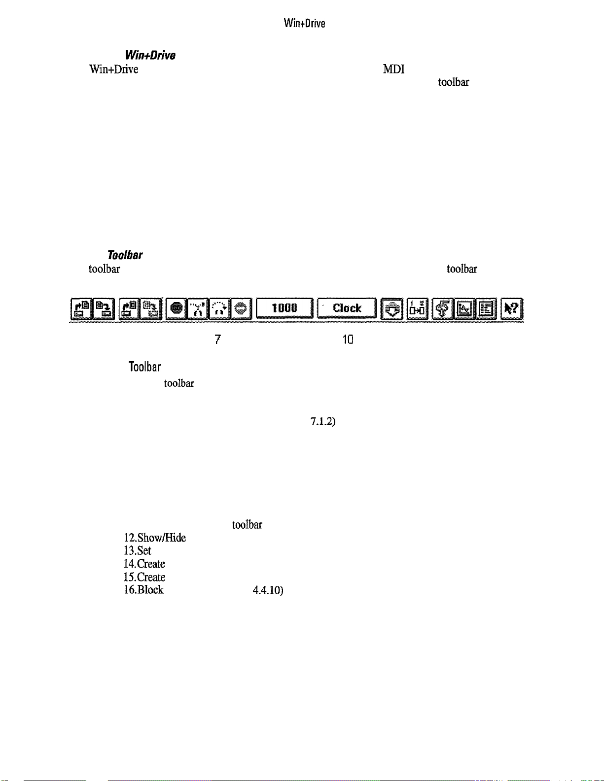
4.4.2
Toolbar
The toolbar provides a fast method to access often used menu items. Clicking one of the toolbar buttons
equals accessing the equivalent menu item.
12 3 45 6
7
8 9
ICI
11 12 13 14 15 16
Figure 4.4.2.1:
Toolbar
By the buttons of the toolbar the following commands can be accessed by a simple mouse click
1. Open a tile (see paragraph 4.2.2)
2.
Save a file (see paragraph 4.3)
3.
Open a compound block (see paragraph 7.1.2)
4.
Update the instances of a compound block (see paragraph 7.3)
5. Restart the simulation (see paragraph 9.5)
6. Simulate one loop (see paragraph 9.5)
7. Simulate several loops (see paragraph 9.5)
8. Stop the simulation (see paragraph 9.5)
9.
Set the number of loops to simulate (see paragraph 9.5)
lO.Display the number of loops that have been simulated (see paragraph 9.5)
11. Show/Hide the block toolbar (see paragraph 4.4.2)
12.Show/Hide the execution order (see paragraph 8.2)
13.Set a probe (see paragraph 9.1)
14.Create a monitor window (see paragraph 9.1)
15.Create a trace window {see paragraph 9.1)
IdBlock
help (see paragraph 4.4.10)
11
Page 22
GEL100340
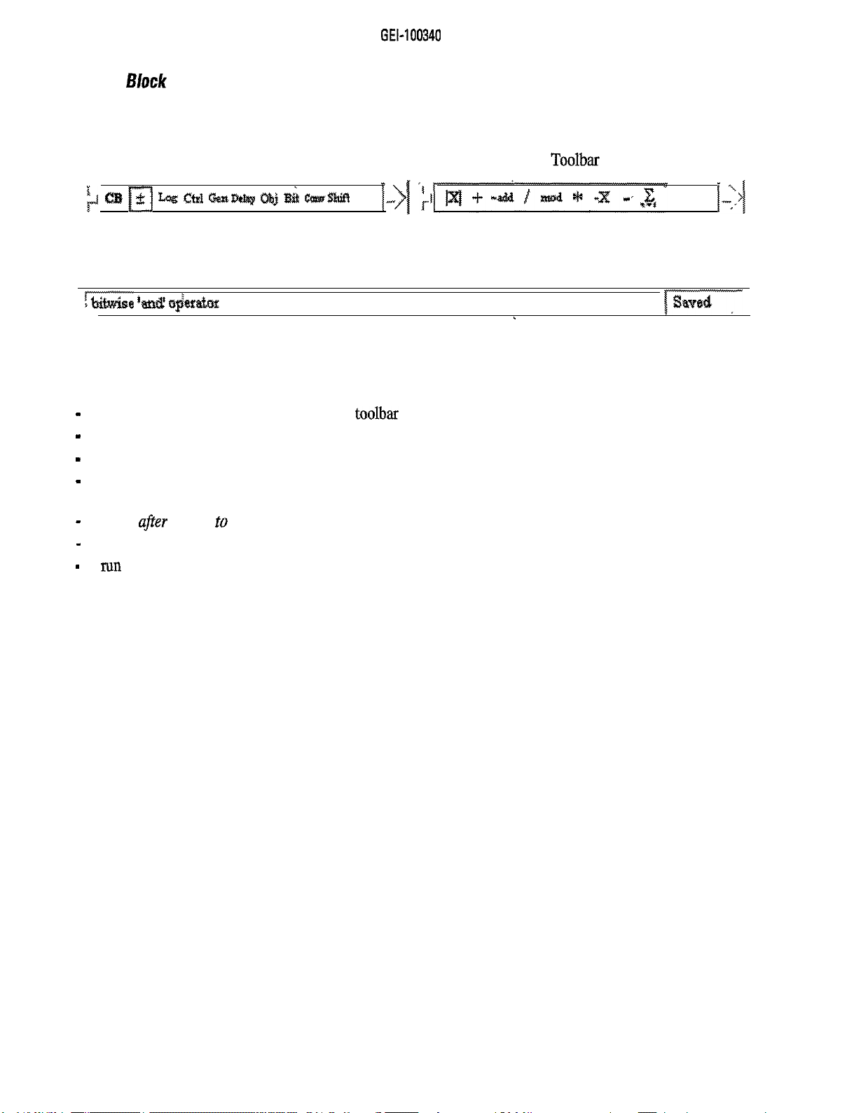
4.4.3 Block
Selection Bar
The block selection bar provides quick access to the building blocks of the schematics. It is divided into two
parts: the left part is used for selecting a group. The members of the selected group are displayed on the right
half of the bar. Placing of a block is done by dragging and dropping a block into the schematic.
The block selection bar can be made hidden or visible by the menu item Block Toolbar of the View menu.
;J CtB fTJ Zag CM GasB&y c&j ah emwmf!
Figure 4.4.3.1: Block Selection Bar
4.4.4 Status Bar
5z$iMse ‘& i$e#atlFnr
,
I
,
lg,,d-
Figure 4.4.4.1: Status Bar
The status bar is located at the bottom of the main window and gives information about the schematic being
edited On the left side the following items are displayed:
-
if the mouse pointer is on a button of the toolbar an explanation of the button is given
-
if the mouse pointer is on a button of the block selection bar, its name is displayed
-
if the mouse is within the schematic during editing the name of the block it is pointing to is displayed
-
in all other cases this part is left empty
The right part of the status bar displays information about the status of the project:
-
saved ufrer
-
changed
-
run if simulation is active.
saving to disk,
after editing changes,
12
Page 23
WintDrive
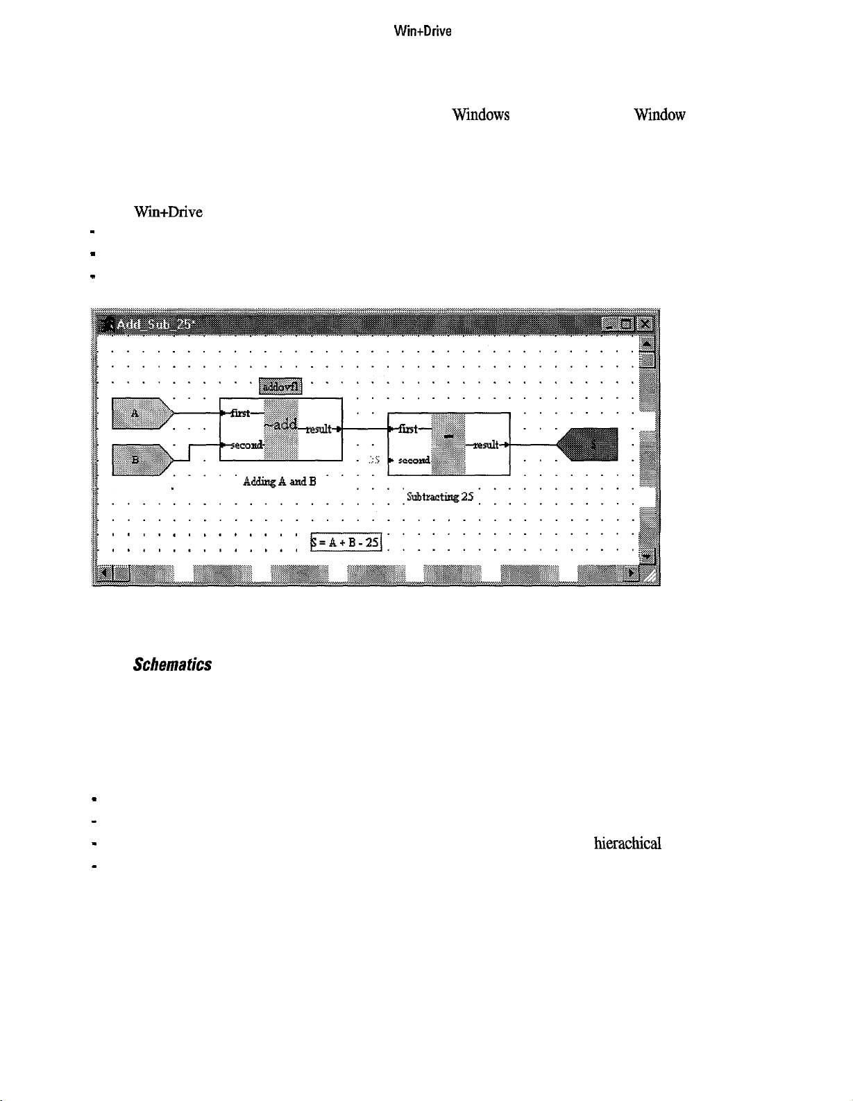
4.4.5 Windows
Within the main window of Win+Drive several child windows can be placed. Each child window can be
maximized, minimized, resized and closed with the standard Wrndows actions. Within the Window menu
there are some items for arranging the open windows (tiling and cascading) and for arranging the the icons of
the closed windows. Another menu item is provided for closing all windows.
The window menu also includes the list of the open windows. Selecting one of these items will change the
focus to the corresponding window.
Within Wm+Drive there are four different types of child windows:
-
schematic windows for the main scheme and for the compound blocks
-
the output window of the code generation and compilation process
-
monitor and trace windows for displaying dam during simulation.
. . . . _ . . . . . . . . . . .
.
............
.
............
Figure 4.451: Schematic Window
4.46
Schemafics
The schematic windows are the main part of a Win+Drive application. They display the structure of the
program to generate and allow graphical editing of this structure.
The title bar of the main scheme always is
bar The schematics windows have scroll bars for changing the actual view within the total schematic. They
can be minimized, maximized and resized.
Within the client area of a schematic window there are the following elements:
-
the blocks of the schematics. These can be basic blocks or compound blocks
-
connections between the ports of the blocks
-
input and output ports within compound blocks for connecting them to the next
-
texts and labels as comments.
AU blocks and connection lines are placed on a grid. Within the page setup dialog (called from the File menu)
the grid can be sized and made visible and printable.
Schematics can be printed on many pages. The boundaries of the pages for print out are visible within the
schematics as fine lines.
Windows
k;=A+B-251:::::::::::::::::
Scheme
while the compound blocks have their names in the title
hierachical
layer
13
Page 24
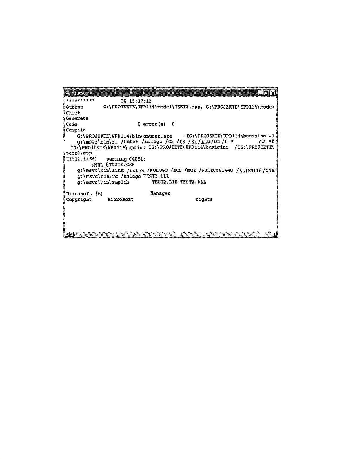
GEL100340
4.4.7 Output Window
Output windows are used to display the messages and errors of the code generation and the compilation. Also
source files can be displayed.
Output windows allow no editing. Only after double-clicking an error
message
the appropriate schematic or
source file that caused this error will be opened.
+*ff******
~Qutput files G:~PROJEKTE\WPDll4~moclel)TEST2.cpp, G:jPROJEKTEjWPD114jmode
i
iCheck tags for Scheme
$Generate code for Scheme
$Code
$Compile
s
i
!
. f IG:\PROJEKTE~WPD114~wpdinc: f IG:\PROJEKTE\WPD114\basicinc /?G:\PROJEKTE
I
,test2.cpp
TESTZ.i(46) : aarnlng C4051: type conversion: possible loss of data
is
1
I
;
$Hlcrosoft
!Copyright
$
I
i
Tue Jul 09
has been generated,
and
G:\PROJEKTEjWPD1141bin\gnucpp.exe -P -IG:jPROJEKTEjWPD114\basicinc
g:jmsvc\bln\cl /batch {nologo /GZ /W3
echo >NUL @TESTZ.CRF
g:\msvc\bin!llnk /batch /NOLOGO /NOD /NOE /PAcKc:61440 faIm:l6 foN
g:\msvc)binjre !nologo TESTP.DLL
g:\msvc!blnjlmplib fnowep TEST2.LIB TESTZ.DLL
link TEST2 for PC
[R]
(C]
Figure 4.4.7.1: Output window
15':37:12
Import Library Hanager Version 1.50
EIicrosoft
Corp 1984-1993.
1996
0 error(s)D warning(s)
fZi fALw fOd
ill rights reserved.
i'D rr
DEBUG"
-
/D
14
Page 25
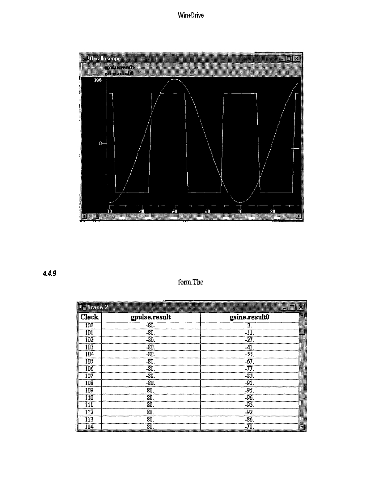
4.4.8 Monitor Windows
Wintllrive
Figure 4.4.8.1: Monitor Window
Monitor windows display simulation results graphically, similar to oscilloscopes. They are used only for
display; no editing is possible.
4.4.9
Trace
Windows
Trace windows display simulation results in tabular form-The contents of trace files can be written to text
files. Editing is not possible.
Figure 4.4.9.1: Trace Window
15
Page 26
GEI-100340
4.4.10 Getting Help
Within the
Help
menu there are items to open the help file and to get help from it. The
Contents
help topic
can be opened directly. Alternatively a dialog for searching help on a specific topic can be opened. Another
menu item is provided for getting help on how to use help.
Context-sensitive help is implemented in Win+Drive. Key ~1
can be used to open a help topic that corre-
sponds to the actual situation of the user.
To get help on the basic blocks the item
Block Help
in the
Help
menu is provided. Also the help button of the
toolbar can be used. After pressing one of these a cursor will be opened with a help symbol. After clicking on
a block the appropriate help page
Selecting
the About
item from
will
be opened.
the Help
menu will open a dialog with general information about Win+Drive
(Version etc.). Clicking on the logo will display different information about the program (version, build date
etc.) in the box.
4.5
For exiting Win+Drive the menu item
kiting Win+Drive
Exit
from the
File
menu has to be selected. If a project is loaded and
modified it is asked whether it should be saved.
Page 27
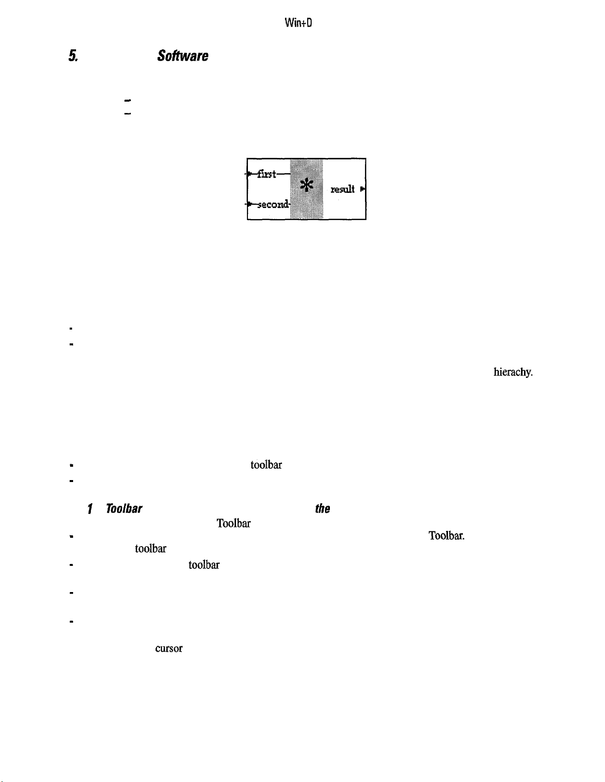
WindI
rive
5.
Creating
Software
Schematics
Building programs using Win+Drive is very similar to creating electrical circuit descriptions. It consists
mainly of two actions:
-
selecting and placing blocks of code onto the schematic
-
and connecting these blocks.
5.1 Placing Software Blocks
Figure 5.1: Block
A block is always the representation of a specific function that is performed by a piece of code. This software
function evaluates input values which are represented by input ports and calculates output values which are
represented by output ports. If the input port of a block is connected to the output port of another then this
block will read the results of this preceding block.
There are two different types of blocks:
-
basic blocks
-
compound blocks.
Basic blocks are the atomic building parts and always represent software code. Compound blocks are repre-
sentations of schematics and are used for dividing the total project into several schematics within a hierachy.
Compound blocks will be described in detail in Chapter 7.
Basic blocks are organized in groups. Since there can be a large number of different basic blocks its easier to
select them if there is this kind of organization and ordering. Groups are normally organized in a way that
basic blocks with similar functions are grouped together (for example arithmetic blocks, logical blocks,
function generators).
For placing blocks onto the schematic two different methods are implemented:
-
placing by drag&drop from the block toolbar
-
and selecting from the insert menu.
5.1. ITooibar
Placing Blocks by Drag&Drop from
the
Block
To place a block from the Block Toolbar perform the following actions:
-
first select the appropriate group by clicking an icon of the left side of the Block Toolbar. Now the right
half of this
-
select a block from the toolbar by moving the mouse onto its icon and pressing the left mouse button. The
toolbar
will display the members of this group
mouse cursor will change to a symbol representing a block
-
hold down the left mouse button and
move
the mouse to the place within the schematic the block should
be placed (Drag action)
-
At this point release the mouse button. The block will be placed at this point (Drop action).
If the mouse is positioned on a point where the block cannot be placed (outside the client area of a schematics
window) the mouse cnrsor changes to a symbol showing that no drop action is possible.
17
Page 28
GEI-100340
5
1.2 Placing Blocks using the
To select a block from the
-
first open
the Insert
Insert
Menu and select the appropriate group. Now a submenu is opened showing the
lnserf
Menu
menu act as follows:
members of this group.
-
select one of them by clicking the menu item. The cursor changes to a symbol representing a basic block.
-
move the mouse to the place the block shall be inserted
-
then click the left mouse key. The block is now inserted at this place,
If you want to stop this action after you have selected a block press the
EST
key.
The groups and blocks that can be selected are defined by definition files which are read and evaluated during
the startup of Win+Drive. To load during a
Basic Block
from the
File
menu can be selected. This basic block will only be available during this session.
W&Drive
session an additional basic block the menu item
Load
To make it generally available it has to be added to the define directory.
5.2 Connecting
S&ware
Blocks
Connection lines between blocks are the graphical representation that one block is evaluating the results of
another one for its own calculation. Therefore connections are always done between the output port of a block
and the input of the next one. One output can be connected to several inputs.
For drawing a connection perform the following actions:
-
place the mouse onto the port of one block
-
press together the
-
while pressing
CXXL
key and the left mouse button
CTRI,
and the left mouse key move the mouse to the port
that
shall be connected. During
this movement a direct line is drawn from the starting point to the actual mouse position
-
after the mouse pointer has arrived at the port that shall be connected release the left mouse button. Now a
rectangular connection line that doesn’t overlay blocks is drawn between the two ports.
If an output shall be connected to several inputs, first draw the connection from this output to one input. Then
start a new connection from a point of this existing connection line to the next input. The starting point will
get the junction of the two connection lines.
Connection lines can also be created between blocks (instead of the ports of blocks). This is used for changing
the execution order (see chapter 8). Creating these lines is done by pressing the left mouse button within the
block center of the block that should be executed first. After holding down the mouse button and moving the
mouse to the block that has to be executed after the first one, the button is released. Now a connection line
between the two blocks is drawn. A virtual output and virtual input are created for this purpose.
Page 29
WintDrive
5.3 Placing Text and labels
In order to have comments on a schematic for explanation texts and labels can be placed. Both have no
function for the code generation and are provided only for readability. Texts and labels are nearly identical;
the only difference is that labels are linked to blocks while texts are not.
53.1
Placing a Text
For placing a text perform the following actions:
-
select the menu item
Text
from the
Insert
menu. The cursor changes to four arrows pointing to the
middle.
-
move the mouse to the point within the schematic the text should be placed
-
click the left mouse button at this point. Now a text “Comment on scheme“ is inserted
-
to change the
initial
string of the text you have to modify it as decribed below.
To cancel this action, press the ESC key.
53.2 Placing a label
To insert a label the following actions have to be performed:
-
select the menu item
-
move the mouse over the block the label should be linked to.
-
click the left mouse over this block. Now a label with the text “Comment on Block [blockname]“ is
Label
from
the Insert
menu. The cursor changes.
inserted below this block.
-
to change the initial string you have to modify it.
To cancel this action press the
5.3.3 Modif’jGng
the Text
ESC
key.
To change a text or label, the appropriate item has to be selected by clicking the left mouse button on it. The
color of the selected item changes to red. By double-clicking or by pressing the right mouse button, a dialog is
opened for entering the new string.
Figure 5.3.3.1: Change Text Dialog
Enter the new text in the
Cancel
leaves it unchanged.
text
field. Closing the dialog by the
OK
button will change its value, while pressing
A text can consist of several lines. The font cannot be changed.
5.3.4 Moving Texts or Labels
To move a text or label to a new position, first it has to be selected by clicking the left mouse button. Then by
holding down the left mouse button while moving the mouse it can be moved to a new position. The movement is finished by releasing the left mouse button.
19
Page 30
GEL100340
5.4 Editing the
Ports
of Blocks
Section 5.2 above explained that the ports of blocks represent input and output variables of the underlying
piece of code and that these ports can be connected together. Drawing a connection line is the most common
operation on the ports of blocks. Other operations are available by opening the ports dialog.
5.4.1 Opening the Ports Editor Dialog
The ports dialog for a block is opened by double-clicking a block or by selecting a block, pressing the right
mouse button to open the context sensitive menu and selecting
Ports..
from this menu. The ports dialog is
used for changing properties of all ports of one block
Figure
5.4.1.1: Ports
Editor Dialog
Within the Ports Editor dialog there are two lists that include all input and output ports. After selecting one of
the ports its properties can be changed by the control elements in the middle of the dialog window. The port
that is selected immediately after opening this dialog is determined by the mouse position at the time the
block was double-clicked or the right mouse button was pressed. Thus the user can determine the initial
selection by double-clicking a port of the block.
5.42 Setting the
Putt
Connection
For each port the type of connection can be changed by selecting an item of the drop down list box. The
following selections are available:
-
None: the port has no connections. Output ports can be left open (if the result is not used). Input ports
have always to be connected to something.
-
Variable: a variable is used for connecting the schematic to the embedding program of the target system.
Variables are described in detail in Chapter 6.
-
Tag: a tag is a connection that is done by setting the same tag on different ports within one schematic.
Tags are useful for connections to many ports. All ports that share the same tag string are connected.
-
Connection line: this choice is selected if a connection line was drawn. Setting the combo box to this
value will cause an error after closing the dialog.
-
Constant: the input of a block will be set to a constant value. Setting an output port to a constant will
cause an error message after closing this dialog.
20
Page 31

Win&rive
5.4.3 Setting the Port Attributes
The port attributes consist of two properties:
-
the name of the port
-
the data type of the port.
The name cannot be changed for basic blocks, only for compound blocks. The data type can be set to the
standard types of the C language:
-
char
-
short
-
int
-
long
-
Uchar (unsigned char)
-
Ushort (unsigned short)
-
Uint (unsigned int)
-
Ulong (unsigned long)
The selections available depend on the definition of the basic block. Especially basic blocks for arithmetic
operations provide a wide choice of data types. During code generation it is checked if the selected data types
fit together.
5.5
Editing Block Parameters
Some basic blocks not only have ports but also parameters to determine their behavior. These parameters can
be considered as internal constants of the block that can be set to fixed values by the user while creating the
schematic. The parameters are changed by opening the parameter dialog. First a block has to be selected, then
the context-sensitive menu has to be opened by pressing the right mouse button and finally the
Parameter..
item has to be selected from this menu.
. . . . . . . . . . . . . . . . . . . . . . . . ...” . . . . . . . . . . . . . .
“..“”
. . . . . . . . . . . . . . . . . . . . . . . . . . . . . . . . . . . . . . . . . . . . . . . . . . . . . . . . . . . . . . . . . . . . . . .
int
I
101
I
. . . . . . . . . . . . . . .
.......................
_..“...” ...................
Figure 5.5.1: Block Parameter Dialog
A parameter is changed by selecting it from the list of available parameters. The text boxes for its name and
type show the actual values. A new value can be entered in the corresponding text box. A command button is
provided to change it back to the default value. Leaving the dialog by
Cancel
leaves everything unchanged.
OK
makes the change while pressing
21
Page 32

GEI-100340
5.6 Changing the View of the Schematic
Schematics can get larger than the window displaying it. Therefore the window shows only a small view on
the entire schematic. This view can be changed in several ways:
-
the position of the view can be changed by the scroll bars and key combinations
-
the magnification ratio can be changed by menu items from the
View
menu and by key combinations.
5.6.1
Positioning the View
The actual position of the view is changed primarily by using the scrollbars on the left and lower side of the
window. There are some key combinations that have similar effects:
-
pressing the cursor keys moves the view into the corresponding direction
-
pressing the cursor keys together with the
CTRL
key moves the view by larger portions in the correspond-
ing direction
-
pressing
-
pressing the
PAGE-UP
HOME
or
PAGE-DOWN
has the same effect as pressing
CTRL+UP
or
cm+~om
key moves the view to the upper left comer of the schematic.
All these key operations can be used to move the view freely over the whole schematic.
5.6.2
Changing the Zoom factor
To be able to see more details or larger portions of the schematic within one window the magnification factor
(also called the zoom factor) can be changed by using menu items from the View menu. Most of these menu
items are also available by key combinations. The following operations are provided:
-
zooming into the schematic (increasing the magnification)
-
zooming out of the schematic (decreasing the magnification)
-
zooming to original size
-
zooming to a magnification that the whole schematic fits onto the window
(ALT+~)
(ALT++)
(ALT+-)
(AL.T+~)
If the zoom factor has a small value texts are no longer displayed. They are only visible if the magnification is
high enough.
5.6.3 Displaying additional Information on the Window
Within the view menu there are items that can be checked to make additional information available:
-
if the
Execution Order
item is checked the order of execution is displayed for each block after code
generation has been executed.
-
if
the
Quick Info
item is checked the name of each port and block is displayed within a small info box
above the cursor position. This box is displayed immediately after the cursor moves over the port of
block.
-
if the Quick value
item is checked the actual value of a port is displayed during simulation after the
mouse moves over it.
22
Page 33

Wirdrive
5.7 Modifying Schematics
A schematic is normally not entered one time but entered and changed several times. Modifying a schematic
is done by performing two steps:
-
select one or more items to modify,
-
then perform the modification.
Modifications can be done in several ways:
-
moving items,
-
duplicating items,
-
deleting items.
5.71
I Selecting
Mocks
and lines
A block, junction, connection line, text or label is selected by clicking on it with the left mouse button. The
selected item will be surrounded by a red rectangle.
To select several blocks or junction press the
SHIET
key and select the next item.
It is also possible to select all blocks and junctions within one rectangular area:
-
Press the left mouse button outside an item,
-
Move the mouse with the left mouse button pressed down. A rectangular box is shown.
-
Release the mouse button. Now all blocks and junctions within this area will be selected.
It is not possible to select more than one connection line segment or more than one text or label at a time.
Multiple selections are only possible with blocks, junctions, inputs and outputs.
If all items within one schematic shall be selected the menu item
Deselection is done by pressing the
ESC
key. All selections disappear
Select All
from the
Edit
menu can be used.
5.7.2
Moving selected items
Selected items can be moved by the following actions:
-
Move the mouse into one of the selected areas (red surrounded).
-
Hold down the left mouse button.
-
Move the mouse with the button held down to the new position. The selected items will be moved together with the mouse.
-
Release the left mouse button at the fmal position.
If blocks are moved the connections are modified in a way that its relative position to the blocks are kept.
Also labels are moved together with blocks so that their relative position to the blocks are kept. If segments of
connections lines are moved the junctions are adapted to the new position.
5.713 Copying and Moving via the Clipboard
Portions of a schematic can be moved or copied within one schematic or between different schematics within
one project by using the clipboard
-
selecting
Cut
from the
Edit
menu (or
CTRL+X)
deletes the selected items from the schematic and puts
them into the clipboard,
-
selecting
-
using
Copy
Paste
from the
from the
Edit
Edit
menu (or
menu (or
CTRL-c)
CTRL-v)
gets the items from the clipboard and places them into the
places a copy of the selected items into the clipboard,
active window. Items that are pasted stay selected and can then be moved to the desired position.
If blocks are cut from the schematic all connection lines to not-selected blocks are deleted. The connection
lines between the selected blocks are kept in the clipboard. Pasting after cutting within the same schematic
doesn’t restore the position and connections of the selected blocks.
If blocks are copied to the clipboard all connections between these blocks are kept and all connections to not
selected blocks are not put into the clipboard.
Pasting from the clipboard is always done to a fixed position in the middle of the active window. After pasting
the items they have to be moved to their final position.
23
Page 34

GEL100340
5.7.4 Resizing items
Basic blocks can be resized. This is done by the following steps:
-
Select the block. It will be surrounded by a red rectangle.
-
Move the mouse to one of the border lines or corners of the red rectangle. The cursor will change to a
double arrow.
-
Hold down the left mouse key and move the mouse to the new size.
-
Release the left mouse key after the required size was achieved.
If the block is getting too small to display texts they will not be displayed. Resizing is always done in grid
units. There is a minimum size that is defined by the number of ports.
5.1;5
Deleting items
Selected items can be deleted by
All items of the schematic will be removed by the
chasing Delete
from the
Edit
Remove All
menu or pressing the
item of the
Edit
menu.
DEL
key.
NOTE: There is no undo feature, therefore deleting should be done carefully.
57.6
Rotating Blocks
Each block can be rotated to all four 90” positions. The image of the block is not changed and the text is
always from left to right. The rotation is selected by a dialog box that is opened after selecting one block,
opening the context-sensitive menu by pressing the right mouse button and then selecting the
Rotate..
item.
24
Figure 5.7.6.1: Rotate Block Dialog
The required rotation can be selected by the radio buttons.
everything unchanged.
OK
performs the change while
Cancel
leaves
Page 35

5.8 Printing Schematics
Wintllrive
For documentation purposes Win+Drive schematics can be printed. Printing is started
from the
File
menu. A dialog appears that is used for setting the print options. There are two modes for
by the Print command
printing schematics:
-
window print mode
-
page print mode
The window print mode is used for draft printouts, while the page print mode delivers document ready prints.
Both modes are started from the Print item of the File menu.
Figure 5.8.1: Window Print Mode Dialog
5.8.1
For printing a scheme in window mode select
Printing in Window Mode
Print
from the
File
menu and then
Window mode
from the tab
riders of the dialog. The window mode dialog appears.
Within this dialog you can change the following options:
the margins of the printing at all four borders in inches. These margins will not be printed. They should be
-
bigger than the printer margins.
the print range can be selected between the visible window and the whole schematic.
-
-
the printing especially for larger schematics can be divided onto more than one page. For this purpose the
Multipage checkbox has to be marked.
-
If the Keep aspect ratio is checked, the magnification in x- and y-direction is the same. Otherwise they are
optimized to fit the schematic to the page.
-
If the Frame around page is checked, a border and a headline will be printed to identify the printout.
OK
starts the printing while
Cancel
aborts it.
Setup
can be used to open the Page Setup dialog.
25
Page 36

GEL100340
Figure 5.8.1.1: Page Print Mode Dialog
5.82
For printing a scheme in page mode select
Printing in Page Mode
Print
from
the File
menu and
then Page Mode
from the tab riders
of the dialog. The page mode dialog appears.
Within this dialog you can change the following settings for the printing:
-
the margins of the printing at all four borders in inches. These margins will not be printed. They should be
bigger than the printer margins.
-
whether all pages of the total schematic are printed or only selected ones. For entering the list of selected
pages, use the format ~,y;x,y.
-
checking Coordinate labels will print coordinates and dotted lines to separate them in x and y directions.
1,1
is the upper left page, 2,1 the page to its right and
1,2
the page below it.
In x direction letters (A, B,..) are used while in y direction numbers are used (1,2,..).
-
checking Frame around page will print a rectangle around each page of the printout.
A printout in Page mode will include a stamp (title block) that is defined in the Page setup dialog.
OK starts the printing while
It is possible to print selected schematics using
checkbox
.and open
the
Cancel
aborts it.
Setup
this
can be used to open the Page Setup dialog.
dialog. For
this
purpose check the
Allow CB printing
dial0g
appears:
26
Figure 5.8.2.1: Block Print List Dialog
By using the two arrows in the middle of the dialog selected items from the lists can be included into or
excluded from the printing. Pressing
OK
ends this dialog.
Page 37

WintDrive
5.8.3
For setting up the page for printing select
Page Setup fur Printing
Page setup
Page Setup dialog will appear.
Figure 5.8.3.1: Page Setup Dialog 1 (page setup)
from the
File
menu or
Setup
from the Print dialog. The
Figure 5.8.3.2: Page Setup Dialog 2 (stamp setup)
Figure 5.8.3.3: Page Setup Dialog 3 (grid setup)
27
Page 38

GEL100340
Within this dialog the following options can be set:
the orientation and size of the paper,
-
the position and definition of the stamp (title block),
- thegrid.
There are checkmarks that determine if the stamp and grid are displayed and/or printed. Also the text inside
the stamp can be shown or hidden.
58.4
Seffing
Stamp Variables
Stamps can include variables (for example for the name of the author, the company, the project etc.). The
stamp variables dialog that is opened from the Page Setup dialog is used to set these variables to text stings.
Figure 5.8.4.1: Stamp Variables Dialog
After choosing one of the variables from the list its name can be inserted into the bottom textbox. The
Default
button can be used to reset the variable to its default value as described in the stamp definition file.
58.5
Stamp definition file format
The size and format of a stamp is defined by a text file with extension
definition file:
[Metric]
pixels
[ Dimension]
350 60
[Position]
Down Right
[Line]
0 15 350 15
0 30 350 30
120 0 120 15
180 15 180 30
[Text]
0 12U Page : @page@" 8 0 @Courier New
120
12 I3 File
0 27m Author
name : @filename@ ,, 8 0 @Courier New
: SAuthorS" 8 0 @Courier New
.smp.
This is an example for the stamp
28
Page 39

WintDrive
200 27 m Date : @date@ ,, 8 0 @Courier New
0 42 w Window :
[Variable]
Author=Mr.
[Bitmap]
‘l:\wpd\smpl.ogo.bmp"
Black
@winname@ ,, 8
321 31
0 @Courier New
The file consists of sections which are introduced by the name of the section in square brackets. After the
section heading one or more lines with information follow. All lines starting with
//are
comment lines and
only for explanation.
The following sections are provided:
[Metric]: can be set
[Dimension]: one
[Position]: one
[Line]:
x-end
pext]:
the font size, the font type and the font name preceded by @. within the string build in ftelds can be used
one line for each line within the stamp follows. Each line includes values for x-start, y-start,
and
y-end
one line for each text follows. Each lines includes the x-position, the y-position, the string (in “
(@date@, @winname@, @filename@
of the schematic being printed. Also text variables can be used which are enclosed by
[Variable]:
one line for each variable; the variable name is followed by = and its default value (i.e.
to
inches, millimeters ar pixels
line
with width and heightfollows
line with
Up or
(numbers separated by spaces)
Downfollowed
and
by Left or
@page@);
tightfollows
“),
thesefields will be replaced by the actual values
$
(i.e.
$author$).
Author=Mr. Black)
[Bitmap]:
thejZename of the bitmap enclosed in” ” is followed by its position (x and y)
29
Page 40

GEI-100340
6.
Connection to External Variables
Programs generated using Win+Drive normally have connections to the environment outside. For example,
set and measured quantities for control have to be read and output values have to passed to servos. For
creating these connections between internal values of Win+Drive generated programs and external ones
variables have to be defined and ports of blocks have to be connected to them. The connections are managed
not directly by the variables but by aliases called logicals.
6.1 Variables and
Logicals
There are two kinds of objects for connecting internal ports to the outside world:
-
variables are used in the generated program and provide the names that are used by external programs,
-
logicals are used in the schematics and are connected to ports. They are mapped to variables.
Variables are initially defined by the file
Target.ini that is read during startup of Win+Drive. During the
execution they can be edited by the variables dialog.
6.2
The variables dialog is opened by the item
The Variables Dialog
Variables
from the
Edit’
menu.
;‘;$,g;. . . . . . . .
..~ . . :.. . . . . . . . . . . . .
‘@ 4
;‘i,;:
. . . . . . . . . . . . . . . . . . . . . . . . . . . . . . . . . . .
I
i&.&Jug
.._......... . . . . . . . . . . . . . . . . . . . . . . .
[iti
.._........ i . . . . . . . . . . . . . . . . . . . .
.
...”
t....
Figure 6.2.1: Variable Editor Dialog
The dialog lists all available variables in a multi column list:
-
Nbr is used for numbering the list,
-
Variable name contains the name. If a variable consists of an array the size is appended after the name in
square brackets (i.e.
-
Data type shows the type.
-
Storage class shows where the variable is defined and available.
FVAR[lUi.I]
is an array of 100 elements).
Pressing the New button will insert a new line into the list with a new variable. Its initial name and attributes
can be edited.
Delete
removes a variable from the list. Variables that are described as read-only in the file
target.ini cannot
be deleted from the list.
To edit a variable the corresponding line must be selected by clicking with the mouse. The name can directly
be edited in the list while the type and storage class are changed by selecting other entries in the appropriate
lists.
The data types are the standard C data types and correspond to the data types of the ports described in para-
graph 54.3.
30
Page 41

WintDrive
The storage class defines where the variable is declared and visible. The following values are available:
-
external variables are declared in the external program and can be used in the generated program. They
get the attribute extem in the generated program.
-
global variables are declared in the generated program and can be used by the external program. They get
no attribute in the generated program.
-
static variables are declared in the generated program and cannot be accessed by the external program.
They get the attribute static.
-
local variables are declared in the generated program, but within the blocks that use these variables (not in
the global scope as compared to static variables).
All changes to the variables are saved by pressing OK. They are stored in the project file. To change the
initial settings the file
target&i
must be edited.
6.3
The Logicals Dialog
While variable names are included into the generated program and are used by external programs, the logicals
are used within Win+Drive to connect ports to these variables. The connection is done by the port dialog that
is described in paragraph 5.4.1. Within this dialog a logical can be selected if the connection type is set to
variable.
The logicals available and their mapping to variables is edited by the
Logicals
item from the
Edit
menu.
Choosing this item will open the Logical Variable Editor dialog.
Figure 6.3.1: Logical Variable Editor Dialog
Within this dialog a list is used for all logicals available. The different columns display the attributes of each
logical. At the bottom of the dialog there are some lists that can be used to change a value of a column of the
selected logical. The columns are used for these attributes:
-
the Nbr is a used for numbering
-
Logical shows the name of the logical,
-
Variable shows the name of the corresponding variable the logical is mapped to. This can be an array. In
this case an index must be entered or the Fixed field can be set to “No”. Toggling between “Yes” and
“No” is done by double-clicking the Fixed field.
-
the data type and storage type of the variable are shown. For variables that are not read-only these attributes can be changed within this list.
Page 42

GEL100340
-
the groups are defined in the
target.ini
files. They are used to put the index of the logical variable into a
predefined range of the total variable (that normally is an array). “*” marks the default group that has no
index checking.
-
the value is provided for setting an initial value. This value is used for initialization of the variable within
the generated program.
-
a comment can be used to describe the logical.
New entries are inserted by the New button, while selected items are deleted by the Delete button.
If an entry
witbin
this list is not correct it is displayed in red color.
From this dialog the variable dialog can be opened directly by a command button.
The list can be sorted by the name of the logicals, variables or group names by choosing the sort criteria from
the list and pressing the Sort List button.
6.4 Connecting Block Ports to f
ogicals
A port of a block is connected to a logical by setting the connections type to Variable in the Port dialog
(described in paragraph
54.1).
Within this dialog all available logicals are listed and can be selected.
32
Page 43

Wintilrive
7.
Working with
Hierachy
and Compound Blocks
Complex projects get soon so complex that it is not possible or useful to have all blocks in one schematic. For
splitting a project into several schematics compound blocks are provided. Compound blocks contain basic
blocks and other compound blocks. Compound blocks are inserted into schematics similar to basic blocks.
The inputs and outputs of compound blocks represent their connection to the upper level of hierarchy and
build the ports of inserted compound blocks.
7.1
Creafing
and Opening Compound Blocks
7.1. ICreating a New Compound Block
A new compound block is created by selecting New from
the Compound
menu, A dialog is opened for
entering the block name.
Figure 7.1.1.1: New Compound Block
After entering the name and pressing
OK
a new window is created that contains no elements,
7.12
To open an existing compound block within the project choose the
Opening an existing Compound
Block
Open
item from
the Compound
menu. A
dialog appeares that lists all existing compound blocks within this project. By selecting an item and pressing
OK
or by double-clicking the item the corresponding compound block is opened into a new window.
Figure 7.1.2.1: Open Compound Dialog
33
Page 44

GEL100340
Z
1.3 Renaming a Compound Block
The name of compound blocks can be changed by selecting item
dialog appears that lists all compound blocks of the project. Selecting
upper text box. This dialog can be used to change the
names
Rename
from
one
allows typing a new name in the
of all available compound blocks without leaving
the dialog.
Figure 7.1.3.1: Rename Compound Dialog
If the name of a compound block
removed
by
renaming a compound block.
is
changed all instances get this new name. No instances or connections are
the Compound
menu. A
7.2
Block Inputs and Outputs
Connections from a compound block to the outside are done by input and output ports.
7.2 IPlacing
input
and Output Ports
To place an input or output perform the following steps:
-
select
Input Port
-
move the mouse
-
press the left mouse button. A new input
or
Output Port
to
the place the input or output should be placed.
from the
Insert
or
output is placed into the schematic with the initial name
menu. The cursor changes its appearance.
Portn
(n is a number which is incremented with each insertion).
To cancel this procedure press
ESC
.
7.22 Renaming Ports
Modifying the name
selecting a port, pressing the right mouse button for the context sensitive menu and choosing the
is
done by the ports dialog. This dialog is opened either by double-clicking a port or by
Ports
item.
The port dialog is similar to the one for basic blocks (see paragraph 54.1) except that now the names of the
ports can be changed.
Renaming the port of a compound block results in deleting the connection lines to this port at every instance
of this compound block.
7.2.3
Changing
the
Size of Ports
The input and output port symbols can be resized. This is done by the following steps:
-
Select the port The port will be surrounded by a red rectangle.
-
Move the mouse to one of the border lines or corners of the red rectangle. The cursor will change to a
double arrow.
-
Hold down the left mouse key and move the mouse to the new size.
-
Release the left mouse key after the required size is achieved.
If the port is getting too small to display the name this will not be displayed.
Page 45

WintDrive
z7.3
Updating and Closing a Compound Block
As long as a compound block is edited its instances in other schematics are not updated. To reflect all editing
changes to these instances the compound block must be saved. This
the Compound
Windows displaying compound blocks are closed by the
menu.
Close
is
item of
done by the
Update Instances
the Compound
item of
menu. If the compound block was changed and not saved a message box appears asking if it should be saved. After closing the
compound block the window disappears.
7.4
Copying Compound Blocks
Often new compound blocks are created from existing ones by copying and then modifying them. To copy a
compound block to a new one the item
Figure 7.4.1: Copy Compound Dialog
Copy
from
the Compound
menu can be used.
The compound block to be copied is selected and the new name is entered into the top text box. After pressing
OK
the new compound block with the contents of the source is created.
7.5
To delete compound blocks select the item
blocks is displayed. Select the item to delete and press
Figure7.5.1: Delete Compound Dialog
Deleting Compound Blocks
Delete
from
the Compound
OK
or double-click the item.
menu. A list with
ail
compound
A compound block can only be deleted if it’s not loaded in a window. Therefore close the window that
displays the compound block to be deleted.
After a compound block is deleted a message appears.
35
Page 46

GEI-100340
7.6
Using Cbmpound BIocks
Using compound blocks in schematics is equivalent to using basic blocks. Placing is done from the Insert
menu or by Drag&Drop operations as described in paragraph 5.1.1. All available compound blocks are treated
as a group of blocks. In the Insert menu the bottom item
Compound
opens a submenu with all available
compound blocks. In the block selection toolbar there is also one icon in the left part (“CB”) that will display
all compound blocks in the right part of the toolbar.
Double-clicking the instance of a compound block will create a new window where the block can be edited.
This is an easy and fast way to change the contents of a compound block from its instance.
1.7
Export and lmporf of Compound Blocks
Compound blocks often describe structures that are not only useful for one project, but can be used also in
other projects. Compound blocks used within one project are stored in the project file with extension.
WDR.
To move them to other projects they can be exported from one project and imported into another. Doing this
the contents of the compound block will be stored in a file with extension.
1.X
I
&port
To export a compound block the item
of Compound Blocks
Export Compound
from the
CB.
File
menu has to selected. First a dialog
appears that lists all compound blocks.
Figure
7.7.1.1:
Selecting the item to export and pressing
Export Compound Dialog
OK
or double-clicking the item selects the block to be exported.
Now the standard windows dialog for entering the filename for export is opened. The default name is the
name of the compound block with extension
pressing
OK
the compound block is saved into the selected file. From this file it can be imported into another
.CB.
After changing the name and directory (if desired) and
project.
36
Page 47

Win+Drive
7.7.2
The import
menu. Firstthe standard windows dialog
Import
ofa
of Compound Blocks
compound block into a project is started by choosing
for entering
the
filename will
Import Compound
anuear.
from
the File
After selection of the file, the import process wilt start. First it is checked if groups, logical variables, variables and compound blocks (as part of the compound block to be imported) with the same name are used
within the compound to be imported and the existing project. The result is displayed in a dialog box.
Figure 7.7.2.2: Import Variables Dialog
“Different” means that the attributes of variables are different. This wilt need modification. For doing this
pressing the
chapter 6. Only the
Edit Logicals
logicals
or
Edit Variables
button will open the
logic&
or variables dialog as described in
and variables that are used by the block to be inserted are listed and can be edited.
After leaving these dialogs the result is updated.
Pressing
the Edit CB action
button
will
open a dialog for selecting the import action.
Figure 7.7.2.3: Import Action
37
Page 48

GEL100340
For each compound block within the list the import action
replace an existing block with the one being imported. Not
can
be chosen. Selecting
Accept
will not import the selected compound
block and keep the already existing one.
After finishing the editing of
logicals
and variables the block can be imported by pressing
is available for editing and insertion within the project.
Abort All
stops the import process.
Accept and Replace will
Import All. Now
it
38
Page 49

Win+Drive
8.
Generating Programs
After the schematics of a program have been created they should be converted to programs that can be
executed either on the PC or on the target system. The total code generation is split into two parts:
-
generating the C program from the schematics
-
compiling the C program to binaries.
8.1
To generate the C program from the schematic select
Generating the Program from the Schematic
Generate C-Code
from the
Tools
menu. This will start
the code generation. Output messages and error messages are placed into the output window.
If errors occured there will be error messages in the output window. Double-clicking these lines will open the
schematic where this error is located and will put the cursor position at the appropriate block or port. The item
that caused the error will be blinking. This can be used to go very quickly to the source of the error.
8.2
Execution
Order
After generating the code the execution order is displayed if the appropriate option was selected within the
View
menu. The order is shown in the left upper corner of each basic block and consists of two numbers. The
first gives the number of the chain of basic blocks in the order they are calculated. Win+Drive always places
blocks whose output values are only used by one other block or variables into a chain. The second number is
the order within this chain. This order is on a stack basis: a block with a lower number will call the block with
the number above. This block will thus be calculated before. Therefor the order of the second number is from
back to front within one chain.
. .
, . . . . . . . . . . . . . . . . . . . . . . . . . . . . . . . . . . . . . . .
Figure 8.2.1: Execution order
To change the execution order, basic blocks can be connected. These connnections are created similar to the
connections of ports of blocks, but now the body of the blocks is selected. A connection line will appear that
extends from one block to another.
39
Page 50

GEI-100340
Figure 8.2.2: Changing the execution order
A block that is connected from its block output to the block input of another by this execution order connec-
tion line will always be executed before. Within the example shown this is done by putting this block into the
execution chain before.
8.3 Compiling the Program
After the code is generated without errors it can be compiled. Selecting the item
Tools
If
menu will start this process. The compiler messages and errors are again placed into the output window.
compile errors occur they are placed into the output window. By double-clicking an error line a window
Compile + Link
from the
with the appropriate source code is opened and the line that caused the error is highlighted. This window is
for text display
The menu item
only;
it cannot be used as an editor.
Make Model
from the
Tools
menu combines the code generation and compilation. It will first
generate the C-Code and, if no errors were encountered, will compile it.
84
The command
Generate a Cross Reference
Variable Cross-Reference
creates a file where we can find all the information about the
variables used.
8.5 Edit
The command
the
Block hns
VMP Editor
opens a graphic editor used to draw the icons for the blocks aud compound
blocks.
8.6 Changing Build Options
It is possible to generate code either for the PC or for the target system. Depending on this choice different
makefiles and different compilers are used. The required target system can be set using the items
tion
and
Target Execution
from the
Options
menu. Another way to set the target system is to press the
appropriate radio button in the settings dialog that is opened by the Settings item from the
PC Simula-
Options
menu.
40
Page 51

Wintllrive
9.
Simulating Programs on the PC
Win+Drive includes a simulation environment for the code that was generated for the PC simulation. The
generated program is put into a DLL that is called from Win+Drive. To display output data of the simulation,
probes can be set. The values of these probes can be displayed graphically in monitor windows (looking
like
oscilloscopes) and in a tabular form in trace windows.
To run a simulation the following steps must be performed:
-
the project must be successfully generated and compiled for the PC simulation.
-
probes must be set for all variables that shall be displayed in monitor or trace windows.
-
the monitor and trace windows have to be defined.
-
the simulation will be started for one or more steps. After each simulation step the actual values of the
ports can be examined using the quick value function of the schematics.
-
now the simulation output can be watched using the monitor and trace windows.
As long as the simulation is running the schematics cannot be changed. The simulation has to be stopped
before making any changes.
91
Setting Prubes
Probes are set on ports of blocks. Only the values of ports where probes are set are traced during the simulation, For setting probes two methods can be used:
-
by an item of the
-
by
the context
Edit
menu, or
sensitive menu (right mouse button) while the mouse pointer is on a connection line or port
of a block.
9.1-l Setting Probes from the Edit menu
Within the
-
-
-
All three menu items act in a similar way:
-
-
-
-
9.
I.2
For setting probes using the context sensitive menu perform the following actions:
-
-
-
Within this dialog you can change the name of the probe. The default name is the block name plus the port
name. If a probe already has this name (because same block name is used elsewhere), then a number is
appended.
Edit
menu there are three items that can be used to set probes:
Set Probe
Create Monitor
Create lkace
will set a probe without automatically allocating it to a monitor or trace window,
will
set a probe and create a new monitor window where this probe is displayed,
will set a probe and create a new trace window where this probe will be displayed.
after selecting the menu item, the mouse pointer changes its icon,
move the mouse pointer to the port that should be probed,
press the left mouse button. Now the port will change its color (the color is set in the
Options
if Create Monitor
menu).
or
Create Trace
was selected also a new window will appear.
Colors
item of the
Setting Probes by the Context Sensitive Menu
move the mouse pointer to a connection line or port of a block.
now press the right mouse button, the context sensitive menu will appear
choose
Set Probe
from this menu. Now the
Set Debug Window
dialog appears.
41
Page 52

GEI-100340
Figure 9.1.2.1: Set Debug Window Dialog
Using radio buttons it can be selected if the probe shall be displayed in a monitor or trace window. The two
lists at the bottom of the dialog are used to select the windows in which the probe will be displayed. Select the
appropriate windows from the right list and move them by the left arrow button to the left list. A probe can be
displayed in several windows.
OK
ends the probe setting while
Cancel
leaves everything unchanged.
9.2 Removing Probes
Removing probes can be done either using the
Remove Probe
item of the
Edit
menu or using the context
sensitive menu while the mouse pointer is on a probe. The actions to be performed are similar to the ones for
setting a probe.
If all probes shah be removed select the
9.3 Configuration of
the
Monitor Window
Remove All Probes
item from the
Edit
menu.
The configuration of a monitor window is done by a context sensitive menu that is opened by the right mouse
button while the monitor window has the focus. The following items are available:
-
Turn Off Monitor
-
Hide Legend
will disable the monitor,
‘Jkrn On Monitor
will hide the description of the displayed probes,
will enable it.
while Show Legend will
display them on
the top of the window.
-
Show Grid
-
Monitor Config
-
List of Probes
will display a grid,
Hide Grid
will make it invisible.
will open a dialog for configuration.
will change the list of displayed probes.
42
Figure 9.3.1: Oscillogram Configuration Dialog
Page 53

WintDrive
9.3. I Monitor Configuration Dialog
This dialog is used for setting the display configuration of the monitor window:
-
the Y range can be set automatically or manually by entering the minimum and maximum values,
-
X and Y axis can be displayed or hidden,
-
Cross lines at the actual position of the mouse pointer together with a display of the x and y values can be
displayed,
-
the x axis range can be set by a scrollbar.
OK will apply these changes while Cancel leaves everything unchanged.
9.3.2 Changing the fist of Probes
Figure9.3.2.1: Setting the List of Probes
The list of probes dialog includes two list boxes. The left one includes the probes that are displayed in the
monitor window while the right one includes all others. Selecting an item and moving it from one list to the
other using the arrow buttons will include or exclude it from display in this window.
Cancel
leaves it unchanged.
OK
ends this setup while
9.3.3 Zoom within the Monitor Window
To enlarge the view in a monitor window a rectangle can be drawn with the left mouse button pressed down.
This area will be zoomed and displayed in the total window.
Pressing the right mouse button while in a zoomed view will go back to the original size.
9.4 Configuration of the Trace Window
The trace window is modified by items from a context sensitive menu that is opened by pressing the right
mouse button while the trace window has the focus. The following menu items are available:
-
Show Grid
-
Align Left
-
List of Probes
and
Hide Grid
and
Centering
control the display of horizontal lines between each line.
control the display of the values.
will change the probes that are displayed in this window (see description of the menu item
of the monitor window above)
-
Save as Text File
the standard windows
will write the contents of the Trace Window to a text file. The filename is entered by
file dialog.
43
Page 54

9.5 Running fhe Model
GEL100340
The simulation of the model is controlled by items from the
-
Go restarts the simulation and sets the variables to its initial values.
-
Step
simulates the model once (one loop)
-
Continue
-
Stop
-if the model has crashed
simulates the model a number of loops that is setup by the Change run steps dialog
terminates the simulation and returns to the edit mode of the schematic.
Unload DLL
can be used to remove it from memory.
Debug
menu.
The actual number loops that have been simulated is displayed in a button of the task bar
The number of loops that are started by the Continue item is setup by the Change Run Steps dialog that is
opened by a button from the task bar.
Figure 9.5.1: Set Run Steps Dialog
9.5. IDisplaying
Values
during Simulation
Besides the display of values in the monitor and trace windows which always display the complete history
during the simulation session, the actual
on by the
Options
Quick Value
menu.
item of the
value
can also be displayed by the quick value option. This is turned
View
menu or by a check field of the
Settings
dialog called from the
If the quick value option is turned on the actual value of a port is displayed if the mouse rests upon it within a
schematic window. A small text window appears. This kind of display is available for all values but shows no
history.
9.52
The actual
-
-
-
-
Changing Values during Simulation
value
of a port can be changed manually by the following actions:
move the mouse pointer over this port,
open the context sensitive menu by the right mouse button,
select
the Change Value
item.
a dialog is opened where the new value can be entered.
44
Page 55

WintDrive
10.
Changing Settings of
Win+Drive
The configuration of the actual project and Wm+Drive can be changed by dialogs that are opened from the
Options
IO.
The scheme settings dialog is opened by selecting
menu.
I Scheme Settings
Scheme Settings
from the
Options
menu.
Figure 10.1.1: Set Scheme Dialog
The two lists include all schematics of the project. Each schematic will be either in the list of compound
blocks (left list) or of schemes (right list). Schemes are root schematics of the project (top level) while compound blocks must be included in other schematics. By using the arrow keys each block can be put in one of
these two lists.
After selecting one of the schematics its name dan be changed. This name is used in the status bar if the
mouse is over its icon in the block selection bar
Figure 10.1.2: Settings Dialog
45
Page 56

GEI-100340
10.2 General Settings
Within this dialog the following settings can be done:
showing or hiding the block toolbar (see paragraph 10.1)
showing or hiding the quick info or quick value text boxes (see paragraph 10.1)
by checking the
hierachical
compound block opening the compound blocks will show the complete path
in their caption if they are opened by double-clicking from their instances in other schematics
the Auto compound block label will ask for the picture of a compound block after it was created by
Compound New
the Overwrite Makefile will cause new
suppresses this
makefile
generation. This is useful if there are user changes in the
makefiles
to be generated with each code generation. Unchecking
makefile
for existing
projects
Page print mode will set the page mode printing as the default after choosing Print from the File menu
the number of simulation loops can be set for updating the monitor windows. This speeds up simulation
since the windows will not be redrawn after each simulation step
using the text boxes additional flags for compilation and linking can be set.
the locations of the compilers can be changed
the filename of the target description file can be set
the PC or target system can be selected for code generation
46
Figure 102.1: Colors Dialog
lg.3 Changing the Colors
The colors dialog is opened by the item Colors from the Options menu. Selecting one of the screen elements
and clicking one of the colors will change it. The effect is visible in the picture at the left side. By the buttons
the palette can be adopted.
Page 57

WintDrive
10.4 Setting up External Tools
Table 10.4.1 lists the tool functions integrated into Win+Drive. Note that these tools may require the installation of programs and/or compiler(s) not supplied with Win+Drive.
The Tools menu can be extended. This is useful for running other programs without leaving Win+Drive. The
Tools item of the Options menu will open the tools dialog.
Figure 10.4.1: Tools Dialog
This dialog can be used for adding and deleting items of the Tools menu. The user defined tools are listed.
Selecting one shows the settings of this tool:
-
the command line includes the name of the program to run. This should include the complete path.
-
the menu text is used in the Tools menu.
arguments can additionally be defined.
the initial directory defines where the tool is started from.
if Ask for Arguments is checlced, a dialog will be opened asking for arguments before the program is
Staaed.
Run in DOS mode will run programs in a DOS box.
if a program is running in DOS mode, its output can be put into the output window
programs can run visible or invisible
Win+Drive can be hidden as long as the tool is running
Tools for DGFC
To
Tools Comments
&e
Generate & compile for DGFC Compile for DGFC The code is generated & compiled GEI- 100339
for the DGFC target
Download code Load firmware Download the generated code into GEI-100339
the DGFC
Configure the DGFC HlBS
The
HIBS contigurator
is called
GEI-100339
Page 58

GEI-100340
48
Page 59

Witdrive
Appendix A
A. I Block library for DGFC
The following Help Topics are available:
Introduction
Block
Blocks in alphabetical order
Note:
This Appendix was current at time of printing. For the latest information, always refer to the on-line
help.
A.2 Introduction
Win+Drive is a graphic editor that permits the development of schemes for any type of target that can be
programmed in C language. A specific library of basic blocks can exist for any target. This manual presents
the blocks for DGFC.
A.3
The
Group
Input port
Parameter
output port
Block
block
represents a basic instruction of Win+Drive and is composed of the following elements:
49
Page 60

GEI-100340
Group
It is used to group the different types of blocks in an homogeneous way, for instance arithmetical, logical etc.
This grouping facilitates the search of blocks when compiling a scheme.
ln
the present version the defined groups are the following:
I/O
Mathematic
Logical
Timer
Delay
Function
Control
Arithmetic
Variable
Generator
//O
Group
This group is composed of blocks that permit the control of I/O devices of the target.
Operator
Akm
Interface to the syuchronous communication structure DGF->DRIVE.
Interface
Interface to the asynchronous communication structure
to the synchronous communication structure
DRIVE->DGF.
DGF->DRIVE.
Interface to the asynchronous communication structure DRIVE->DGF.
Drives the
CPU test point.
DeviceNet master coumumication
Read
slave DeviceNet communication area
Write slave DeviceNet communication area
Access to optional I/O card
Mathema
tic Group
This group contains mathematic blocks.
Computes the value of Xy
Calculates the square root
Block
name icon
alarm
ods
ids ids
Oda
ida ida
tpC tpC
CfiX CfiX
lfii
wfix wfix
fun
Block
I
name
pWr
sqlt
ah-m
OdS
oda
rfix
fuu
woo11
icon
Pm
sqrt
WOOllZ3
50
Page 61

WintDrive
Logical Group
This group contains all those
blocks
performing logical operations. Only integer data
(id) can be treated by
these blocks.
There are two operator sub-groups:
l
Control of data as a unique logical variable (logic), that means:
TRUE if equal to zero
FALSE
l
Control of data as a group of 16 logical variables, one for each bit that forms the
if different from zero
data
itself
(bitwise).
Operator Block for
logic
data Block for
bitwise data
name icon name
and
or
land
lor
xor lxor
not blot
Operator
a&&b
a II b
a-b
!a
and
or
xor aAb
not
Block
name icon
D
Flip-flop
with set and reset inputs
J-K Flip-flop with
preset and clear inputs
ffd
ffjk ffjk
Timer Group
This group contains temporization blocks. Only integer data
icon
a&b
alb
-a
(int)
WC012
ffd
wm3
can be treated by these blocks.
Delay Group
This group contains blocks that have two purposes:
.
.
define the starting point in the execution of a circular connection
perform one cycle delay
Operator
one cycle delay
one cycle delay
Block for
name icon
idelay
int
data
dly
Block for
name icon
fdelay
delay
float data
Clly
delay
woo14
51
Page 62

Function Group
This group contains special functions:
GEL100340
Operator
Function
name icon
Diameter and thickness observer
Speed observer
Operator
Block for
name icon
UP/DOWN counter
icnt cnt
int
data
diamobs diamobs
speedobs speedobs
Vii015
Block for
float
data
name icon
fcnt cnt
wQ316
Control Group
This group contains all those blocks performing operations that will condition the execution of a scheme.
There are three operator sub-groups:
l
Control of integer data
l
Control of floating data
l
Control of integer
(int)
(float)
(int)
and floating point
(float)
data
52
target / simulation
selector
Operator
one-way executor
two-way executor
four-way executor
eight-way executor
T
Block for
int
name
exe1
exe2
exe4
exe8
and
T
wall7
float data
icon
exe
exe
exe
exe
WOO18
Page 63

WintDrive
Arithmetic Group
This group contains all those blocks performing arithmetical operations.
There are two operator sub-groups:
l
Controls integer data
l
Controls floating point data
(id)
(float)
Variahh
Group
This group is composed of blocks that permit the handling of variables and the conversion of types of data.
Operator
Generator Group
This group is composed of blocks that permit the generation of wave-forms.
53
Page 64

Input port
GEL100340
Represents the element from which the
A
block
may have
An Input port
l
AVariable
l
AConstant
l
The Output port of another block through a connecting line
l
The Input port of a Compound through a connecting line
only
one
Input port,
can be connected to the following elements:
block
multiple
receives information in the
Input ports
or no
scheme
Input ports.
In any of the above mentioned cases, the connection can be performed only if the type of the elements comply
with each other.
Parameter
This element is used for the block configuration. The configuration of a
block
can be defined only from the
graphic editor and cannot be changed while the program is being loaded on the target.
A
block
may have
only
one
Parameter,
multiple
Parameters
or no
Parameters.
output port
Represents the element from which the block issues the result of its operations.
A
block
may have
Au Output
l
AVariable.
l
The Input port of another block through a connecting line.
l
The Output port of a Compound through a connecting line.
only
one
Output port,
multiple
Output ports
or
no Output ports.
port can be connected to the following elements:
In any of the above mentioned cases, the connection can be performed only if the type of the elements
comply with each other.
54
Page 65

A.4 Blocks in alphabetical order
WintDrive
imod ilnul
iprc isel
ivar
lxor
OdZl OdS
rbit
land
lllfti
l-fix
T tbd
tpc wbit
imux
isub
blot
mitf
or
speedobs
true
WfiX
ine
itf
lor
not
Pm
sqrt
lmr
xor
w@322
55
Page 66

GEL100340
alarm
Description
This block enables alarm notification on the digital keypad using
Input ports
name type alternative type function
g
C int
int
gate (rising edge)
alarm cause
output ports
AI-BRICK-USR
woo23
: c.
name
0
Parameters
tvue
iut
alternative
tvue function
alarm presence : 0 - alarm not present
No
parameters
1 - alarm
present
woo24
56
Page 67

Wint Drive
and
Description
This block carries out a bit wise “and” operation of the integer data read by input ports a and b.
It shows the result of the operation in output port o.
T 1 T 1 T
Input
ports
name type
a
b
output ports
name typeI alternative type 1 function
0 int 1
Parameters
int
int
woo26
alternative type function
Data
Data b
Result of the logical operation
No parameters
a
~0027
wooti
57
Page 68

cfix
GEI-100340
il
i2
B
trim
fix
*l
42
co3
r
[411
Description
It performs a master
and sends them to the appropriate slave, retrieves the words received from the slave and writes them to output
words
(01,02
occur for 1 cycle or for
DeviceNet
communication
(LocalBus).
and 03). It also manages the timeout
tmo
cycles.
This block gets the input words (il, i2 and i3)
signaling(to
r output) when the communication does not
Input ports
Name
il int
i2 int
i3
tmo int
Type
int
Executed
always
always
always
always
Function
1 st word to be transmitted
2nd word to be transmitted
3rd word to be transmitted
number of cycles after which the r output is set to 2.
we274
Output ports
Name Type
01
02 int
03
r
int
1 st word received
2nd word received
int
3rd word received
int
~
communication status:
if 0 the block has found valid received words since previous
execution
if 1 the block has not found valid received words since
previous execution, but not for more than tmo cycles
~0275
58
Parameters
Name
slave-id int
len-w int
fix-dst-ind
len-r
fix-src-ind
Alarm causes
Code 1 Function
0
slave-id
1
len-w
2
ind-dst-fix
4
len-r
5
ind-src-fix
8
the
sum of
9 the
200
sum of
the program contains more than 32 cfix blocks
Type Function
MACID(address) of the slave
number of words to be transmitted to the slave
int
index of slave FWA where to write the 1st words
transmitted by the master
number of words to be received from the slave
int
int
index of slave
by the slave
must be positive and not greater than 63
must be positive and not greater than 3
must be positive and not greater than 47
must be positive and not greater than 3
must be positive and not greater than 47
len-w
and
ind-dst_fix
len-r
and
ind-src-fm
FWA
where to read the 1 st words transmitted
exceeds 47
exceeds 47
~0276
wo277
Page 69

WintDrive
delay
Description
This
block has two purposes:
l
define the starting point in the execution of a circular connection
l
perform one cycle delay
Input ports
name
iI float
type
alternative
I
I
type function
IData
i
Output ports
name type alternative type function
0
float
Data i delayed one cycle
Parameters
name
IniCondition
We
float
alternative type function
Initial condition
ImDortant:
Kept only for compatibility with old versions.
For all versions ,from January
the
1st 1997, it will be deleted.
of the
output
WC030
woo31
WC032
59
Page 70

GEL100340
diamobs
C Unuind
b WMmtThrZ
b WMmtThrZ
C MinDirm
C MinDirm
b M.uDiam
b M.uDiam
C MaxThick
C MaxThick
C Initialir*
C Initialir*
L 1niDi.m
L 1niDi.m
C IniThuck
C IniThuck
Thtck
Thtck
l
Description
The DIAMeter OBServer block estimates winder diameter
measured line speed
constants: Taul[sec]
(LineSpd) and
and Tau2[sec].
winder motor speed
(Diameter)
(WMotSpd)
and material thickness
(Thick)
from
using a algorithm with two time
It is used to estimate rewinder or unwinder diameter with or without dancer.
GearRt
UnitsSys
[>l]
is gear-box ratio of winder.
is a input that controls units of line speed, winder motor speed, diameter and thickness. The follow-
ing table explains all available units system:
unltssys
Line speed Winder motor speed
0 - European units meters/ruin rev/min
1 - USA units
feethin
rev/min inches IniI
Diameter
mm
Thickuess
mm
otherwise - International System metershec raclhec meters meters
of units
Control
(3)
input can enable or disable
the
functionalities of
diamobs
block according to the following table:
60
Page 71

WintDrive
Control
0
1
Description
Functionalities are all enabled: diameter and thickness are estimated from line speed
(LineSpd) and winder motor speed (WMotSpd)
1
Diameter and thickness estimation are disabled, but diameter is updated according to
actual thickness. This is used during speed match and when torret is rotating. In this
case material path is changing so diameter estimation has to be disabled, however
,
diameter is increasing (or decreasing if unwind) of
If thickness estimation is disabled (when
1
below) and
otherwise
cal to
’
Control=2.
Functionalities are all disabled: estimated diameter and thickness are constant.
This case is identical to Control=1 when thickness estimation is disabled (when
or
Tau2 are
StartingThickness
Unwind
and diameter decrease when
input indicates direction of winding: rewinder and diameter increase when
unwind = 1.
thickness
set to
le9
is set to 0).
Tat11
or Tau2 are
is zero (when
StartingThickness
[set], see below) and thickness is zero (when
actual
thickness.
set to
le9
[set], see
is set to 0) this case is identi-
unwind
= 0, unwinder
Taul
Diamobs block can control increment or decrement of diameter according to direction of winding: rewinding
or unwinding. For
this porpose IncDecDis
(Increment and Decrement Disabling) and
Unwind
(Unwinder)
inputs are provided. The meanings of these inputs are described in the following table:
IncDecDis
0
different from 0
different from 0
Unwind
i3Ily
0
Description
Estimated
diameter is tiee
Estimated diameter can only increase (rewinder)
different from 0 Estimated diameter can only decrease (unwinder)
xvccMn
Diamobs is a algorithm with two time constants:
Taul [set] and Tau2
[set]. These inputs determine time that
observer takes to estimate diameter and thickness.
The simplest case is when user needs to estimate only diameter: Tau2 must be set to
le9 [set]. Taul [set]
is
diameter estimation time constant. It represents the same concept of time constant in electronic analog circuits
and it is equivalent to the product of Resitance and Capacitance. It is the time that estimated value takes to
reach 63% of its steady state value. After four times time constant reaches steady state value (98%).
More complex case is when user needs to estimate both variables: diameter and thickness. This is the case
when material is very thick.
If for example user wants to estimate diameter with a time constant of 2 [set] and thickness with a time
constant of 10
Taul
[set]
In general terms the least value between
[set],
to 10
he has to set
[set]
is exactly equivalent).
Taul
[set] to
Taul
2 [set]
and
Tau2 [set]
to 10 [set]
(Tau2 [set]
to 2 [set] and
and Tau2 is the time constant of diameter estimation while the
largest value is the time constant of thickness estimation.
Diamobs can estimate diameter and thickness with accuracy depending on winder motor speed
(WMotSpd):
the higer winder motor speed, the more accuracy estimation will be. When winder motor speed is close to
zero, estimations have to stop. For this purpose two winder motor speed thresholds are provided
and
WMotThr2).
WMotThr2
time constants start very high and decrease until
WMotThrl
WMotThrl
When
WMotSpd
is below
WMotThrl
estimation is completely enabled. When
Taul
must be below
and
WMoThr2
WMotThr2.
values depends on speed sensor accuracy and on sample time of the control. The
estimation is disabled. When
WMotSpd
and
Tau2
is between
when
WMotSpd
WMotSpd
WMotThrl
reaches
and
(WMotThrl
is above
WMotThd
WMotThrl.
less accnrate sensor and the shorter sample time, the higher thresholds have to be.
61
Page 72

GEI-100340
With two digital encoders with a resolution of 1000 counts/rev each and a sample time of 10 msec,
WMotThrl
Minimum diameter
are provided to limit possible error estimations.
User
can initialize
diameter
and
WMotThr2
(MinDiam),
should be larger than
maximum diameter
10 rpm
(MaxDiam),
Zero
diameter and thickness using
(Diameter) and thickness (Thick) are
Initialize
respectively set
and
100 rpm
maximum
respectively.
thickness (MaxThick)
is minimum thickness.
input. When this input is different from zero
to IniDiam
and
IniThick.
inputs
62
Page 73

Input ports
WintDrive
Name Type
LiueSpd
WMotSpd
GearRt
unitssys int
Control
Unwind
IucDecDis
Taul
Tau2
WMotThrl
WMotThd
M&am
MaxDiam
MaxThick
Initialize
IuiDiam
IuiThick
Executed Description
float
always Measured line speed
float always Measured winder motor speed
float always
Wmder gear-box ratio
always Units systems for line speed, winder motor speed, diameter and thickness
irlt
always
Controls the functionalities: O=all enabled, l=Diameter and thickness
estimation are disabled, but diameter is updated according to actual
thickness: otherwise=all disabled
int
int
always
always
Winding direction: O=rewinder;
Disables free diameter: O=diameter free; c>O=diameter can only increase
or decrease deDendinP on Unwind innut value
float
always
First observer time constant [set]. The least value between Taul and
Tau2 is the time constant of diameter estimation while the largest value
is the time constant of thickness estimation
float
always
Second observer time constant [set]. The least value between Taul and
Tau2 is the time constant of diameter estimation while the largest value
is the time constant of thickness estimation
float
always
Fist winder motor speed threshold; when WMotSpd is below this value
estimations are disabled. When WMotSpd is between WMotThrl and
WMotlbr2
time constants starts very high and decreses until Taul and
Tau2 when WMotSpd is reached WMotThrl.
It must be below WMotThr2.
float
always
Second winder motor speed threshold; when WMotSpd is above this
value estimations are enabled. When WMotSpd is between WMotThrl
and WMotThr2 time constants starts very high and decreses until Taul
and Tau2 when WMotSpd is reached WMotThrl.
It must be above WMotThrl .
float
float
float
int
always
always
always
always
Minimum allowed estimated diameter
Maximum allowed estimated diameter
Maximum allowed estimated thickness
When different from zero, estimated diameter and thickness are
resnectivelv set to IniDiam and IniThick
float
only if Initialize=0
Estimated diameter is set to this value when Initialize input is different
from zero
float
only if Initialize=0
Estimated thickness is set to this value when Initialize input is different
oO=unwinder.
Output ports
Name Type
Diameter
Thickness float
float
Description
Estimated Diameter
Estimated thickness
woo38
63
Page 74

Parameters
Name
StartingDiameter
StartingThickness
Type
float
float
GEL100340
c
Description
Diameter using by observer as a initial estimated diameter
value
Thickness using by observer as a initial estimated thickness
Page 75

WintDrive
exe1
Description
This block permits
connecting lines, as a function of the status of input port z, 0= not-performed branches, l= performed
branches.
The branch has to be connected to the input port a and executed when exe block is enabled.
the execution
of a
branch,
that is a group of blocks connected to each other through
In any case, the value read by input port
a
is lost.
From output port o the status of input port z is issued.
Input ports
name type
2
a
int
float
alternative type
int
fimction
Block enabler:
= 0 The branch connected to input
=
1 The branch connected to
branch to be
performed
output ports
name type alternative type function
0 int
See also: exe2, exe4, exe8
status of
input port z
port
input port
a
is not performed.
a
is
performed.
woo41
v&MO
65
Page 76

GEI-100340
exe2
Description
This block permits the execution of
connecting lines, as a function of the status of input port z, 0= not-performed branches, l= performed
branches.
The branch has to be connected to one of the input ports a..b .
If the exe block is enabled, the execution sequence of branches will be as follows:
1”
branch connected to input port
2”
branch connected to input port
branches,
a.
b.
that is a group of blocks connected to each other through
In any case, the value read by input port
a,b
is lost.
From output port o the status of input port z is issued.
Input ports
name type alternative type
Z
int
function
Block enabler:
== 0 The branch connected to input ports
=
1 The branch connected to input ports
float
float
int
int
1” branch to be performed
2’ branch to be performed
Output ports
name type
0
int
alternative type function
status of input port z
a,b are
a,b are
woo43
not performed.
pexfomxd.
woo42
66
See
also:
exel, exe4,
exe8
Page 77

WintDrive
exe4
2
a
b
c
a
i
Description
This block permits
connecting lines, as a function of the status of input port z, 0= not-performed branches, l= performed
branches.
The branch has to be connected to one of the input ports
If the exe block is enabled, the execution sequence of branches will be as follows:
1”
branch connected to input port
2” branch connected to input port
. .
4” branch connected to input port
the
execution of
branches,
a.
b.
d.
that is a group of blocks connected to each other through
a..d .
III any case, the value read by input port
a..d
is lost.
From output port o the status of input port z is issued.
Input ports
name type
Z
int
alternative
type
function
Block enabler:
== 0 The branches connected to input
== 1 The branches connected to input port
a
b
C
d
float irlt
float
float int
float
int
int
lo
branch to be
2’ branch
3’ branch to be
to
be
performed
performed
4’ branch to be
Output ports
name type
0
int 1
alternative type function
Status of input port
See also: exel, exe2, exe8
performed
performed
2
port
a..d are not performed.
a..d
are
performed.
woc4l
67
Page 78

GEL100340
exe8
Description
This block permits
connecting lines, as a function of the status of input port z, 0= not-performed branches, l= performed
branches.
The branch has to be connected to one of the input ports
If the exe block is enabled, the execution sequence of branches will be as follows:
lo
2” branch connected to input port
the execution
of
branches,
branch connected to input port
that is a group of blocks connected to each other through
a..h .
a.
b.
8” branch connected to input port h.
In
any case, the value read by ‘input port a..h is lost.
From output port o the status of input port z is issued.
68
Page 79

Input ports
Win+ D rive
name e
Z int
alternative type
T-
int
int
int
int
int
int
int
int
Output ports
name type
0 int
See also: exel, exe2, exe4
alternative type function
function
Block enabler:
== 0 The branches connected to input port
== 1 The branches connected to input port
1 O branch to be
2’ branch to be
3” branch to be
4’ branch to be
5” branch to be performed
6” branch to be
7” branch to be
8” branch to be performed
Status of input
performed
petformed
performed
performed
petiormed
performed
port z
a..h are
a..h are
not performed.
performed.
WOO41
Page 80

GEI-100340
fabs
0 =
lal
Description
It calculates the absolute value of a floating point variable.
Input ports
name type
a
Output ports
name type
0
Parameters
float Data
float
alternative type function
a
alteruative type function
Absolute value of data
No parameters
woo4a
a
wM)49
woo25
70
Page 81

WintDrive
fadd
o=a+b
Description
It calculates the sum of two floating point variables.
Input ports
name type
a
b
Output ports
name type
0
Parameters
float Addend
float
float
alternative type function
Addend
alternative type function
Result of the sum
No parameters
woo51
woo52
71
Page 82

fass
Description
It duplicates a floating point variable.
Input ports
GEI-100340
o=a
d=a
name type
a
Output ports
name type
d
0
Parameters
float
float
float
alternative type function
Data
a
alternative type function
Copy of data
Copy of data
No parameters
woo54
a
a
we055
woo25
72
Page 83

WintDrive
fchs
=-
0 a
Description
It changes the sign to a floating point variable.
Input ports
name type
a
Output ports
name type
0 float
Parameters
float Data
alternative type function
a
alternative type function
Value of data a with changed sign
No parameters
woo.57
woo58
73
Page 84

GEL100340
fcnt
enabh
step
UP
preret
set
cnt
actual
I_
clear
t
Description
UP/DOWN float counter.
Input ports
:
Output ports
uame
type
I
actual
Parameters
1 float 1
name
start-value
alternative typeIfunction
I
actual count value
tme
float
alternative type function
Initial condition of the output
woa62
74
Page 85

WintDrive
fcmp
Description
It compares the data read by input port a with the data read by input port
If a < b it shows 0 in output port o.
If a = b it shows 1 in output port o.
If a > b it shows 2 in output port o.
if(a<b)
o=o;
elseif
( a == b )
o= 1;
elseif
( g > 2 )
0 = 2;
b.
Input ports
name type
a
b
float
float
alternative type function
output ports
name type alternative type
0
float Result of the comparison
Parameters
Data
a
to
Data b to
fknction
No
parameters
be compared
be compared
woo63
wDo64
75
Page 86

GEI-100340
fdela
y
Description
This block has two purposes:
l
define the starting point in the execution of a circular connection
l
perform one cycle delay
Input ports
name
i
float
Output ports
name type
0
float
Parameters
name
IniCondition
type
alternative type function
Datai
alternative type function
Data i delayed one
tw
alternative type function
float
cycle
Initial condition of the output
v&O56
wM)67
76
Page 87

WintDrive
fdiv
o=a/b
Description
It performs a division of two floating point variables.
Input ports
name type
float
it
Output ports
name type
0
Parameters
float
float
alternative type function
Numerator
a
Denominator
alternative type function
Result of division
No parameters
b
woo70
woo71
77
Page 88

ferr
Description
It compares two floating-point data.
ifa
== b it shows 1 in output port o, otherwise it shows
Input ports
name
type
alternative type function
GEL100340
0.
a
b
float
float
Output ports
name
0
type
Parameters
int
Data a to be compared
Data
b to
be compared
alternative type function
Result of the comparison:
l->a==b
0
-->
No parameters
woo25
WC073
otherwise
woo74
78
Page 89

ffd
d
ck ffd
Win+Drive
9
Pr
clr
Kll
w
Description
D Flip-flop with set and reset inputs.
Input ports
name type
d
ck
pr
clr
int
int clock (rising edge Q=D)
int preset
int
alternative type function
Data
input
clear (low-level Q=O
(low-level Q=l)
Output ports v
name type
Q
qn
int
int
alternative type function
output q
negative output
v&m
q
woo77
Parameters
Truth table
Ck
F
T
T T
T T
T T
T T
A
->
F
->
T
->
Q
-->
!Q
->
No parameters
pr
ck
X
F
X X
X
A
A
F
T
d
X
F F
T
X
X
q
F
T
;
Q
qn
T
F
T
!YJ
!Q
woo79
rising edge
value
equal zero FALSE (0)
value different from zero TRUE ( != 0)
output value
negative output value
79
Page 90

GEL100340
ffjk
Description
J-K Flip-flop with preset aud clear inputs.
Input ports
name type
.
ck
k
pr
Ck
Output ports
name type
4
qn int
Parameters
Truth tableTruth table
int
int
int
int
int
int
alternative type function
Data input
j
clock (rising edge)
Data input
k
preset (low-level Q=l)
clear (low-level
alternative type function
output q
negative output
No parameters
Q=O)
q
WC081
80
A ->
F
->
T
->
Q
-->
!Q ->
v/O083
rising edge
value equal zero FALSE (0)
value different from zero TRUE (!= 0)
output value
negative output value
Page 91

WintDrive
fv
Description
It compares two floating-point data.
If a >= b it shows 1 in output port o, otherwise it shows 0.
Input ports
name
type alternative type function
a
b
float
float
Data
Data
output ports
name type alternative type function
0
Parameters
int
Result of the comparison: 1
a
to be compared
b
to
be
compared
No
parameters
0
->
-->
~0084
a >= b
otherwise
~0085
81
Page 92

GEL100340
f#
f
Description
It compares two floating-point data.
If a > b it shows 1 in output port o, otherwise it shows 0.
Input ports
name
type
a
b
float Data
float
Output ports
name type
0 int
Parameters
alternative type function
a to
be compared
Data b to
be compared
alternative type function
Result of the comparison: 1
No parameters
-z= a > b
0
-->
otherwise
woo25
woo87
~0088
82
Page 93

f/e
Description
It compares two floating-point data.
If a <= b
Input ports
it shows 1 in output port o, otherwise it shows 0.
Win+Drive
name type
a
b
float Data a to be compared
float
output ports
name type
0 iut
Parameters
alternative type function
Data b to be compared
woo90
alternative type function
Result of the comparison: 1 -> a C= b
0 -> otherwise
WOO!21
No parameters
83
Page 94

GEI-100340
Description
It compares two floating-point data.
If a c b it shows 1 in output port o, otherwise it shows 0.
Input ports
;;
1 alternative type
m311
1
Output ports
function
Data
a to be
Data b to be CornDared
compared
name type
0 int
I I
Parameters
alternative type
function
Result
of the
No parameters
I
comparison: 1 -> a < b
0
-->
otherwise
Page 95

Win-drive
fmod
o=a%b
Description
It calculates the remainder of the division between two floating point variables.
Input ports
name type
float
ii
float
Output ports
name
0
float Remainder of division
Parameters
alternative type function
Numerator
a
Denominator
@ye alternative type function
1
No parameters
b
wDo96
woo97
85
Page 96

fmul
o=a*b
Description
It performs a multiplication of two floating point
Input ports
GEL100340
variables.
name type
a
b
Output ports
name
0
Parameters
float
float
type
float Result of multiplication
alternative type function
Factor
a
Factor
b
alternative type
function
No parameters
wows
woo99
woo25
86
Page 97

WintDrive
fmux
Description
It reads the status of input port g.
It reads input port a or input port b or input port c as a function of the status of input port g.
If input port g is = 0, it reads input port
If input port g is = 1, it reads input port
a.
b.
If input port g is = 2, it reads input port c.
In any other case it reads input port c.
It shows the read data in output port o.
if (g==O)
0 = a;
elseif(g==l)
o = b;
elseif(g==2)
0 = c;
else
0 = c;
Input ports
name
R
a
b
type
float
float
float
int
alternative type
Selector of the input port to be read
This input port is
Attention:
blocks that could eventually
port
a are
This input port is
Attention: if input port g is different from one, the
blocks that could eventually be connected to input
port b are
This input port is read only if input port g is different
from zero or one.
Attention:
blocks that could eventually be connected to input
port c are not performed.
read
if input
only if input port g is =
port
g is different from zero, the
0.
be connected to input
not performed.
read
only if input port g is = 1.
not performed.
if input port g is equal zero or one, the
87
Page 98

Output ports
GEL100340
name type
0
Parameters
float
alternative type function
Data read by input port a orb or c
No parameters
16.50
88
Page 99

WintDrive
fine
Description
It compares two floating-point data.
If a != b it shows 1 in output port o, otherwise it shows 0.
Input ports
name type alternative type function
a
b
output ports
name
0
Parameters
float Data a to be compared
float Data b to be compared
Qw
int
alternative type function
Result of the comparison: 1
{No parameters
->
a !=
b
0 -> otherwise
Will02
xv0103
89
Page 100

GEI-100340
fprc
Description
It controls the storage of the previous data as floating point data.
It shows the data read by input port i in output port o.
In output port p it shows the data read in the previous cycle by input port
It stores internally the data read by input port
i.
i.
If input c (clear) is different from 0 (TRUE) it shows the data read b input port Y in output port
are then stored inside the block.
static float buf;
p; these
data
if(c) buf=v;
p=buf;
buf = i;
0 = i;
Input ports
name type
i
C
float Input data
int
alternative type function
Clear: if different
port v is issued by output port
V
float
Value issued in output port p if input port c is
different from 0
output ports
name type alternative type function
P
float
Ifc
== 0 data read in the previous cycle by input
port i
if c != 0 data read by input port v
0
float Data read by input
fi-om
0 the value read by input
p
port
i
wolO<
V/O106
90
Parameters
1
No parameters
 Loading...