

Page 1

6KCV3OOllK
InterbusS
GE
industrial
Control Systems
Page 2
GEI-100445
CONTENTS
1.0 INTRODUCTION . .................... ............... ...... ....
1.1
Information ......................................................... .................................................................................... ........................
HARDWARE DESCRIPTION . ....... ..................... .....
2.0
2.1 Drmensrons, weight, protectron level..
Mountmg..
2.2
2.3
Power
2.4 Connectors
Switches . .
2.5
LEDs ..... .....
2.6
Technical
2.7
2.8
Interface .................................................................................... ..........................................................................................
3.0 BASIC INFORMATION ABOUT INTERBUS-S
3.1
Service Models .....................................................................................................................................................................
3.1.1 Short
3.1.1.1
3.1.1.2
3.1.1.3
3.1.2 Objects description
4.0 SERVICES SUPPORTED BY THE
4.1
Context Management
4.1.1
4.1.2 Abort..
4.1 3
4.2
Variable Access Services .2
4.2 1
4.2 2
4.2.3
4.3 VFD Support Servrces
4.3.1 Status..
4.3.2 Identify..
DRIVE PARAMETERS
5.0
6.0 HOW TOCOMMUNICATE..
61
Process Data Channel Control
6.1.1
6.1.2 PDC Output data Descriptor
6.1 3 PDC Output Enable..
7.0
INTERBUS-S ALARM
Description
7.1
7.2
Communication Status.. .............................................................................................................................................
Alarm Recovery ...................
7.3
8.0 PROCEDURES FOR THE BEGINNING AND THE END OF THE PCP CONNECTION..
9.0 HANDLING OF THE DRIVE ALARMS ....
10.0 SERVICE ERROR CODES AND OPERATION RESULT
11.0 VIRTUAL DIGITAL INPUT/OUTPUT CONTROL..
11.1 Vu-tual drgital input..
11.1.1 Descriptors
11.2
12.0 PARAMETERS HANDLING THE OPTION (DGF)
12.1 Description of parameter send a command to DGF option
12.2 Description
12.3
13.0
14.0
15.0
Virtual digital output ........................................................................................................................................................
11.2.1 Descriptors vrrtual d&al
Example
12.3.1
12.3.2
12.3.3
12.3.4
GLOSSARY ..................................................................................................................................................................
ABBREVIATIONS .......
REFERENCES
............................. ........................................................................................................................................
Supply
................................................ ......................................................................................................................
................................... ...................................... ...... ....
................................................... ..................................................
..........................................
Features
service
Client
Services
Service primitives.
Initiate
Reject.......................................................................................................................................................................
Read.
Wrote .
Information
PDC Input data Descriptor..
Wrrtmg
Example writing DGF parameter .....................................................................................................................
Reading DGF parameter.............................................
Example for the reading DGF parameter ................................................................................................................
................................................................................................................................................................
description.
and
Server..
with
and without
...................................................................................................................................................................
...........................................................................................................................................................................
....................................................................................................................................................................
...............................................
Report..
...............................................................................................................................................................
....................................................................................................................................................................
............................................................................................................... .........................................................
of reading value of DGF parameter.. .......................................................
for access DGF parameters
DGF parameter ................
. .
...................
....................................................................................................................................................
....................... ............................................................................................................................
...................................................................................................................................................
.........................................................................................................................................................
Servrces..
Varrable
...................................................................................................................................................
................................
.....................................................................................................................................................
............................................................................................................................................
.....................
...........................................................
.......................................................................................
of virtual digital
....... ._.
................................................................................................................................. 4
confirmatron
6KCV300INS
..........................................................................................................................................
Access Services..................................................................................................
.................................................................................................................................
....
.... .... ........................... .... .......... .... ....
.........................................
..... ........................... ......
.................................
input
.........................................
output.............................................................................................................................
......................................
.....................................................................
....................... ..............................................
...
........
..................................................................
.........
................ .....
....
.................................................
........................
....................................................................................................................
CARD ................................... ............................................................
.............................................
...
.....
...................................................... ....................................................
.......................... ..............................................................
......................................................
............................................
..................................................
....................................................................................................
................................................................................................ ............. ....
................
.....
........
...................................................................................
.....
..................................................................................
............................................................................................
................................. ..................................................
...................
............................................. .......................
............. .....................................................................
....
............. ..............................................
.... ..........
.......................................................................
...
...................................................................
.........................................................
....
................................................................
...............................................................
.....
..................................................
..................................................................... 34
.... ..... ......
...
.... .....
...............................................
...................... .........................
....................................................
..................................................
.
..........
............................................
....
.............................................
...........................................
._ .
...........................................
...
...............
.....
.......... ......
........
.... 10
..... 20
.....
3
3
.4
5
6
6
6
.6
7
7
8
8
8
8
9
.9
9
10
10
10
10
10
10
10
11
11
11
11
12
13
14
21
22
23
23
23
.23
25
25
26
28
28
...
28
29
30
31
32
33
33
33
34
35
36
36
3 6
Page 3
Interbus -
S
This manual is updated according to the
Variations of the number replacing
The identification number of the sottware version can be read on the label of the EPROM chip mounted on
the card.
6KCV300lNS
<cX),
have no influence on the functionality of the device.
software version
V2.XOO.
1 .O INTRODUCTION
This manual describes the option card
Interbus-S network.
The DV300 and AV300 drives can be connected to the network through this card.
This manual is intended for design engineers and technicians responsible for the maintenance,
commissioning and operation of InterBus-S systems. A basic knowledge of Interbus-S is assumed. For
further information refer to ((Reference Manual for
1. I
Information
6KCV300lNS
Interbus-S-PCP),.
for the connection of
inverters
and converters to the
InterBus-S
It allows the interconnection of field devices produced by different manufacturers into a single system.
InterBus-S
(physical layer), layer 2 (data connection layer) and layer 7 (application layer). Because of costs and
efficiency the 3rd through 6th layers have not been implemented.
The 7th layer of Interbus-S is made up of two parts, PMS (Peripherals Message Specification) and LLI
(Lower Layer Interface); the
obtained with LLI.
The purpose of PMS is to supply the user with a Standard interface to several automated devices which are
able to communicate with Interbus-S thus obtaining an
PMS also supplies a subset of services defined in PROFIBUS and it is based on FMS (Fieldbus Message
Specification) of PROFIBUS; uniformity with the automated MAP system (
Protocol) is obtained even with a limited use of the PROFIBUS protocol.
is a
field
Bus designed for automated applications and industrial control.
architecture is based on the communication model
compatrbility
between the PMS layer and 2nd layer (Protocol Data Link) is
(<open
communication,> system.
ISO/OSI (IS0
7498).
Manufactoring
InterBus-S
uses layer 1
Automation
Page 4
GEL100445
2.0
2.1
HARDWARE DESCRIPTION
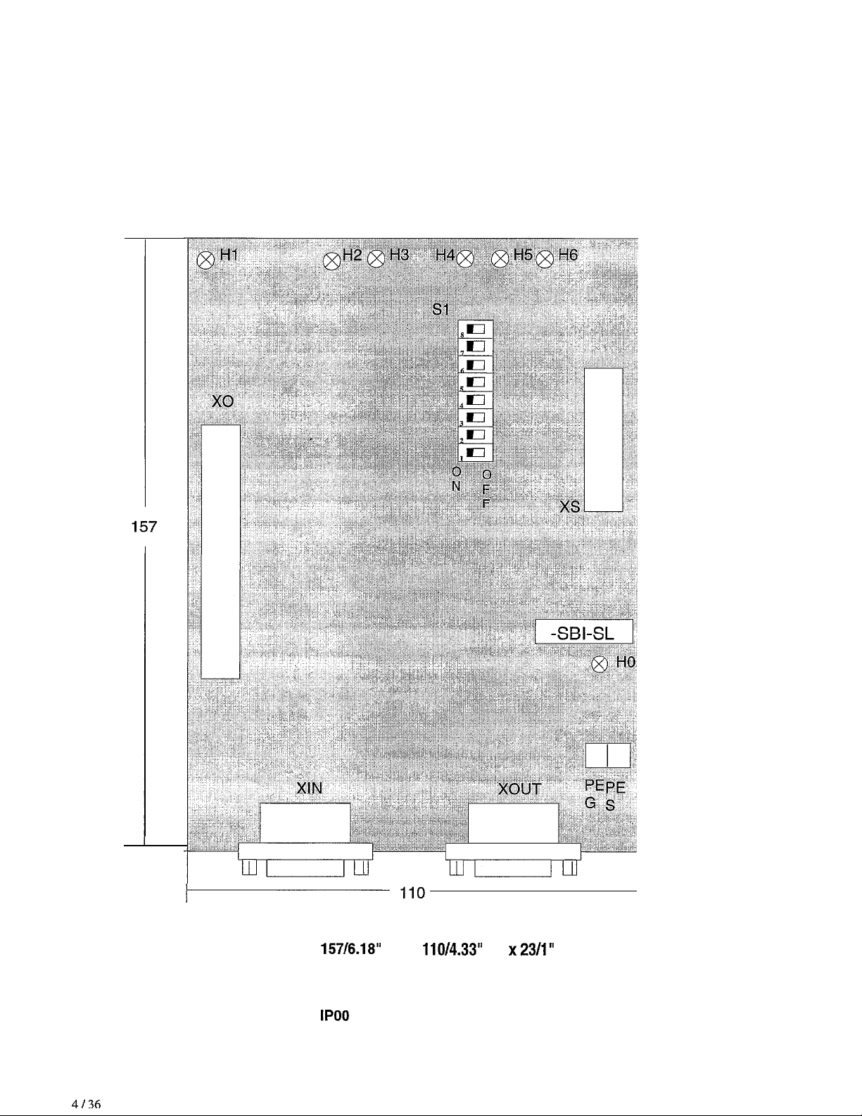
Dimensions, weight, protection level
4136
Dimensions (mm/inches)
Weight
Protection level
157/6.18”
200 g (7.102)
IPOO
(H) x
110/4.33”
(L)
x23/1”
(D)
Page 5
Interbus -
S
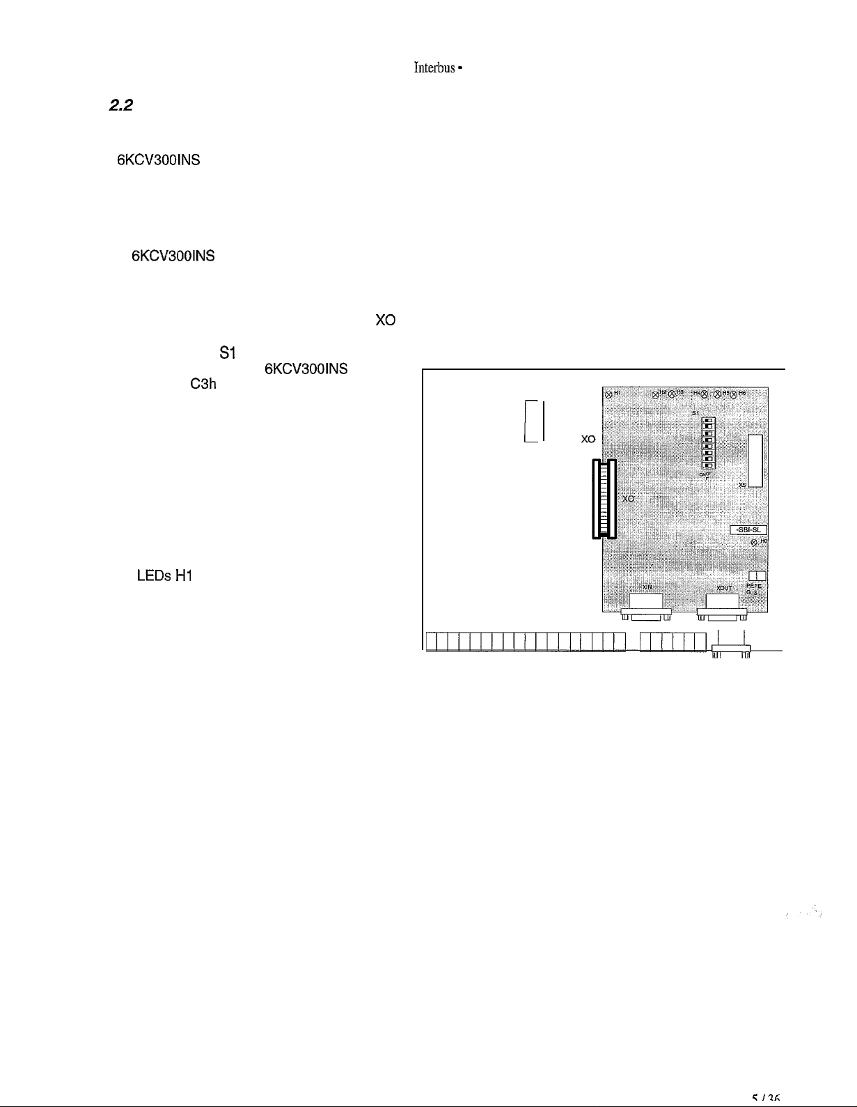
2.2
The
6KCV300lNS
cable with connectors.
1. Switch the drive off.
2. The
Hereby we are representing as an example the card R-TPD3.
Connectors linking the Bus are placed in the same direction of the terminals belonging to the regulation card.
3. The flat cable is connected to the connector X0 already existing on the cards.
4. The dip switch Sl determines the Slave
identification code; for
this code is
and it absolutely can not be changed
otherwise the Master will not be able to
identify the card correctly .
5. Link the input local Bus cable to the
connector XIN and eventually the output
cable to the connector XOUT.
Mounting
6KCV300lNS
C3h
cards are provided with a kit made up of 4 spacers, 4 screws, washers and a 40-pole fiat
card must be fixed with the screws and the spacers to the regulation card.
6KCV300lNS
(Slave on local Bus PCP)
card
I
6. Switch on the drive and supply the local
Bus.
7. The
8. The LED H6 lights up when the Bus is
LEDs Hi
active.
The LED H3 lights up when a PCP service
is required.
and HO light up.
Page 6
GEI-100445
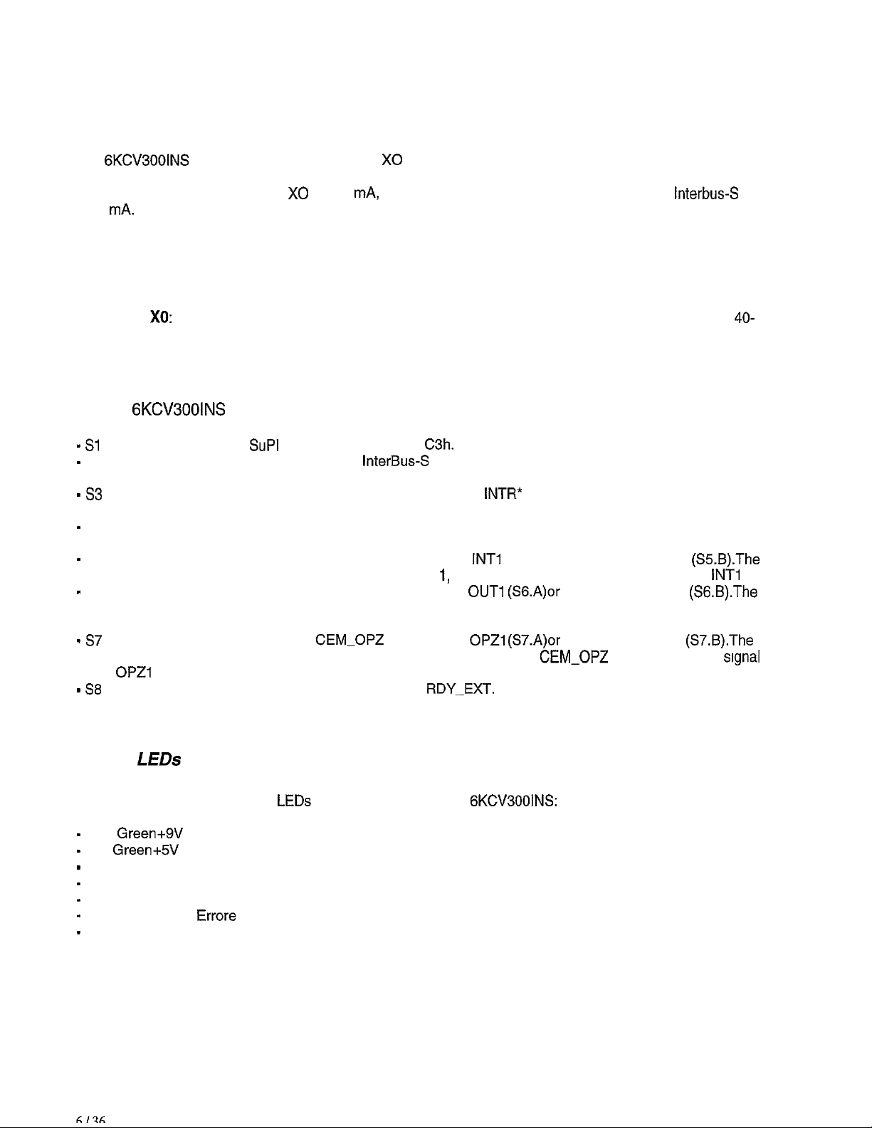
2.3 Power Supply
The
6KCV3001NS
and through the local Bus line InterBus-S There is no need to supply the card from the outside.
The current draw of the connector X0 is 350
is 70 mA.
card are supplied through the X0 connector which links them to the drive regulation card
mA,
while the current drawn from the local Bus line
2.4 Connectors
Interbus-S
Connector X0:
It allows to connect directly the InterBus-S interface card to the regulation card; it is
pin connector.
2.5 Switches
On the
- Sl
-
s2
- 53
-
s4
-
s5
-
S6
- 57
- 58
6KCV300lNS
Configuration Switch
It is used to connect the shield of the
has a default connection.
It is used to connect the signal INT-OPZ to the signal
(S3.B). Default S3.B.
It is used to connect the reset of the regulation card TRST to the reset circuit of the interface. It is
inserted by default.
It is used to connect the signal INT-OPZ to the signal
interface card is configured per default as OPTION 1, therefore INT-OPZ is linked to the signal
It is used to connect the signal OUT-OPZ to the signal
interface card is configured per default as OPTION 1, therefore OUT-OPZ IS linked to the signal
OUT1 .
It is used to connect the signal
interface card is configured per default as OPTION 1, thereforei
OPZl
.
It is used to connect the signal BSY to the signal
card there are the following Switches:
SuPl
II, their value must be
InterBus-S
CEM-OPZ
C3h.
connection cables to the GND supply reference. It
OUT1 (SG.A)or
to the signal
RDY-EXT.
INTR*
(S3.A) or to the port P1.4 of CPU
INTl
(S5.A) or to the signal INT2
to the signal OUT2
OPZl (S7.A)or
It is inserted by default.
to the signal OPZ2
GEM-OPZ
is linked to the
40-
(%.B).The
INTl
(S6.B).The
(S7.B).The
signal
.
2.6
A series of diagnostic and state
-
HO
-
Hi
-
H2 Red
-
H3 Yellow Communication (LBDA).
-
H4 Red Disable the Extended RB Interface (RBDA).
-
H5 Red
-
H6 Green Active lnterbus (BA).
LEDs
Green+SV
Green+5V
LEDs
are present on the cards
(Line Power Supply).
(Regulation Power Supply).
Reset.
Errore
(Error).
6KCV300lNS:
Page 7
Interbus -
S
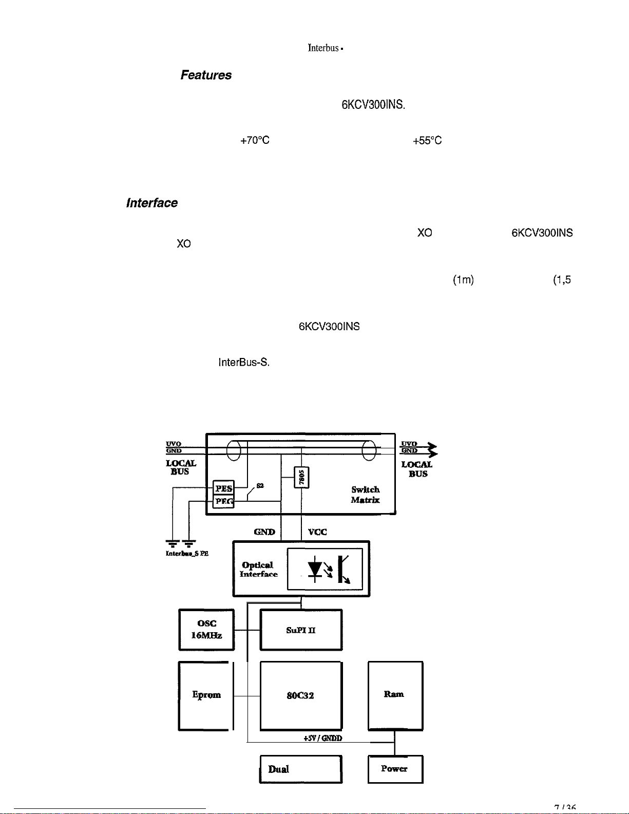
2.7 Technical
The basic model of the Interbus-S interface card is called
According to the type of the drive connected, you can find several variants.
The card used must correspond to the specific drive.
The storage temperature is -20°C
drive temperature they are connected to.
2.8
The card must be installed on the regulation card of the drive so that the X0 connector of the
cards is near the X0 connector of the regulation card, maintaining the link connectors to the line
INTERBUS-S in a downward direction. The tools provided with the card have to be used for the mechanical
connection. A 40 pin Flat Cable is necessary for the electric connection. As far as the connection to to the
Local Bus INTERBUS-S is concerned, you have to use the cables IBS PBC 100
m) which have to be linked to the connectors XIN and XOUT. If the device in use is the last of the Local Bus
line, the connector XOUT should not need to be linked to any cable.
The GND ground reference connection of the
PEG (ground), which has to be connected in one single point to the other PE terminals of the units belonging
to the same section of Local InterBus-S and to the PE terminal of the BK (Bus Terminal) modulus which
generates the local section of
lnferface
Feafures
InterBusS.
6KCV300lNS.
+7O”C
and the operating one is 0°C
6KCV300INS
+55”C
These are adequate to the
6KCV300lNS
(lm)
or IBS PBC 150
card can be carried out through the terminal
(1,5
The shield ground connection of the cables of the Local Bus Interbus-S can be carried out through the PES
terminal , which has to be connected in one single point to the other PE terminals of the units belonging to
the same section of Local InterBus-S and to the PE terminal of the BK (Bus Terminal) modulus which
generates the local section InterBus-S.
EpWIO
soc32
c
+SVIQ54DD
I
Dual Port Ram
Page 8

GEI-100445
3.0
PMS provides the user with some services allowing the
required by all the applications; for specific applications regarding a profile some limitations exist.
The services offered take into consideration the following criteria:
BASIC INFORMATION ABOUT INTERBUS-S
<(open
communication,. The whole service set is not
The service set becomes suitable for the application field of
The uniformity with PROFIBUS is only partially guaranteed.
The services available must be compatible with PROFIBUS.
The times required for the application must be taken into consideration.
The services correspond to an object orientated planning.
InterbusS.
3.7 Service Models
The service models allow to process an object; a part of the object is implicitly specified (for example it is
determined by the interface PMS). The other part is explicitly specified in the object dictionary (called OV).
The access to an object is possible through some services and the addressing can be logical (through an
index) symbolical or implicit.
3.1.1 Short service description
The following services can be used with PMS:
-
Initiate.
-
Abort.
-
Reject.
-
Status.
-
Identify.
-
Get OV.
-
Read.
-
Write.
-
Information Report.
3.1 .l
.I
From a communication point of
VFD functionalities (Virtual Field Device) of the remote user process. The Server, on the contrary, carries out
these duties and provides the Client with its VFD functionalities.
A user process can be both Server and Client (the
Client and Server
view
a Client is an application which assigns some duties in order to use the
6KCV300lNS
cards can only act as Servers).
The Client services are only used to assign a duty; such duty is transmitted to the Server through a PDU
message (Protocol Data Unit).
Page 9
Interbus -
S
3.1 .I .2Services with and without confirmation
There are services with and without confirmation.
As for the services
services without confirmation there is no acknowledgement on the side of the Server.
wrth
confirmation, the Server can acknowledge the duty carried out; in the case of
3.1.1.3
As for the Client, the assignment of the service is specified by the primitive
the acknowledgement on the side of the Server by the primitive
For the Server, the primitive to which the service is assigned to is called
is sent by the primitive
Service primitives
<<Request,,,
&onfirmatiom~.
-Indication>>,
((Response>>.
3.1.2 Objects description
Espkit
PMS identifies explicitly the following objects specified in the object dictionary:
objects
Object dictionary.
Access to single variables.
Access to vectors.
Access to structures.
while the reception of
while the identification
Page 10

GEI-100445
4.0 SERVICES SUPPORTED BY THE
Hereby you have a description of the services which a Master can require to the
6KCV300lNS
CARD
6KCV300lNS
cards .
4.1 Context Management Services
The services regarding the system control are the following:
Initiate
Abort
Reject.
4.1.1 Initiate
This service can establish the connection between two communication Partners. To achieve this, there is an
information exchange about the possible services accepted and the length of PDU.
4.1.2 Abort
This service terminates the previously established connection between two communication Partners.
4.1.3 Reject
With this service PMS rejects a non-allowed PDU.
4.2 Variable Access Services
The services regarding the access to the variables are:
Read
Write
Information Report.
.2
Variable Access Services
4.2.1 Read
This service gives the possibility to read the values of a parameter, an array or a structure. As far as arrays
and structures are concerned, their values can be entirely read (by setting the subindex to zero) or read the
elements one by one (by setting in the subindex the number of the element involved in the operation).
4.2.2 Write
Page 11

Interbus -
This service gives the possibility to write the values of a parameter, an array or a structure. As far as arrays
and structures are concerned, their values can be entirely written (by setting the subindex zero) or written the
elements one by one (by setting in the subindex the number of the element involved in the operation).
S
4.2.3 Information Report
This service is an information message carried out by the Slave in the Master direction: this service has not
been previously required by the Master.
The Slave generates this service when for example it has to indicate an alarm condition.
4.3 VFD Support Services
The following VFD services are supported:
Status
Identify.
4.3.1 Status
The status of the user device (Slave) can be read through this service.
4.3.2 Identify
Information suitable for the identification of VFD (and therefore of the user device) can be read with this
service.
Page 12

GEI- 100445
5.0 DRIVE PARAMETERS
The user parameters have an Offset referred to the type of drive linked to Interbus-S; in order to obtain the
parameter index, the specific Offset for that drive has to be added to the index of the drive parameter.
At present the Offsets are the following:
DRIVE OFFSET (in
hexadecimal)
AV300 2000hex
DV300 2000hex
Example:
The DV300 drive parameter having the index
the index 200Fhex.
The Drivecom parameters start with the index 6000h (hexadecimal); for their indexes see paragraph
5.2.1.1.4.2 of the manual
The Drivecom parameters for the configuration of the process data channels
implemented on all the cards in order to allow the configuration of the above-mentioned channels, which are
later described.
All the drive parameters can be transmitted through the PCP; as for the meaning of the parameters see the
drive manual.
DRIVECOM
,
PROFILE 21.
OFh
(which corresponds to 15 decimal) with InterBus-S has
6000h,
6001 h and 6002h are
Page 13

Interbus - S
6.0 HOW TO COMMUNICATE
Communicating is possible through a series of services demanded by the Master to the Slave; such services
are:
-
Context Management:
-
Initiate.
-
Abort.
-
Reject.
-
VFD Support Services:
-
Status.
-
Identify.
-
Variable Access:
-
Read.
-
Write.
-
information Report
In order to communicate through the Communication Channel it is necessary that the Master sends to the
Slave a request to initiate the communication (Initiate Service) and that the Slave acknowledges a positive
response.
After the
reading and writing.
The Slave can only carry out the services requested by the Master; it can not ask for any service: only with
the Information Report can the Slave carry out a service for the Master without it being asked previously.
When the Master asks the Slave to read a parameter, it must send the parameter index and eventually the
subindex; if the data is correct, the Slave responds positively with the parameter value, otherwise it responds
negatively indicating the error cause.
As for writing a parameter, the Master sends to the Slave the parameter index, eventually the subindex and
the writing value; in this case the Slave responds positively if the writing has been carried out successfully
otherwise it responds negatively indicating the error cause.
The Slave always verifies the validity of the index, of the subindex, of the access rights and in the case of
writing the length of the value sent and if the value is in range of the stated limits; it verifies also if in that
moment the parameter can be written.
As for error codes, the composition and the meanrng of the different services, see the Reference Manual for
InterBus-S ( see reference chapter).
communication
is initialized, the Master can request to the Slave all the other services, such as
Page 14

GEI- 100445
6.7
Process
Dafa
Channel Control
This function allows to assign drive parameters to the Process Data Channel Bytes.
In InterBus-S ring the
6KCV300lNS
cards occupy a total of four words (WORD); the first Word (that is 16 Bit)
is represented by the PCP, while the following three are avaliable for the Process Data Channel
(abbreviation PDC).
Representation of the words occupied in InterBus-S ring by the
. . . . . . . . . . . . . . . ..*......
.
WORD 1 l l WORD 2 n . WORD 3 l l WORD 4 l
.
.
PCP
. . . . . . . . ...* . .
The
6KCV300lNS
The data read by the
the
6KCV300lNS
. . . . . . . . . . . . . . . . . . . . .
. .
.
.
.
.
. .
l
. . . . . . ..*............
e......
. . . . . . . . . . . . .
l lPDC 1 l . PDC 2 l l PDC 3 l
..t.......
card can both read and write the Process Data Channel.
6KCV3001NS
card from InterBus-S are referred to as output data; the data written by
card in Interbus-S are referred to as input data.
l Process Data
l Drive parameters
.
.
.
l *m Input data descriptor
Process
Channel
Control
.
l Process data
l Drive parameters
.
.
.
l ** Output data descriptor
.
l -- Output data enable
.
. . . . . . . . . . . . . . . . . . . . . . .
. . . ...*.....
6KCV300lNS
..*........
cards :
*
Assigning the drive parameters to the communication object
c<PDC
are read with cyclicity by the Master.
Assigning the drive parameters to the communication object
transmits to the Server with cyclicity such parameters.
Input data Descriptor,,, such parameters
(<PDC
Output data Descriptor),, the Master
Page 15

Interbus
\
-S
The assignment of the processed data to specific drive parameters can be set. To this purpose the
Input data
data can be enabled or disabled by the
Descriptor>>
and
<<PDC
Output data
Descriptor>>
<(PDC
output Enable= communication object .
communication objects are involved . The output
How it works:
Process Data from Interbus-S
.
<cPDC
.................................
I
l 1=2*3*4*5*6*7*8* PDC Output Channel
.................................
........
.................................
l 1*2*3*4*5*6*7*8* PDC Output Memory
.......................................................
.........
........................
..............................................
..............................
.........
........
.......................................................
l
P.l*P.l*P.l*P.l=P.2*P.2*P.2*P.2*
.................................
.
PARAMETER 1 l PARAMETER 2 l
.................................
.
DRIVE
PARAMETERS
.................................
.
PARAMETER 1 l
.................................
l
P.l*P.l*P.l*P.l*P.2*P.2*P.2*P.2*
PARAMETER
2 l
.................................
..............................
.........
........
..............................
.................................
l 1*2*3*4*5*6*7*&* PDC Input Memory
.................................
........
.................................
~1*2*3*4*5*6*7*8*
.................................
.
PDC Output
***Enable
**PDC Output data
-descriptor
.
PDC Input data
***descriptor
PDC Input Channel
.
.
.
.
.
.
I
Process Data for Interbus-S
Page 16

GEI- 100445
The
<<PDC
Input data Descriptor>> communication object (input data for the Master) determines the drive
parameter assigned to the Bytes of the Process Data Channel . The
<<PDC
Output data Descriptor),
communication object (output data for the Master) determines the Bytes of the Process Data Channel
assigned to the drive parameter.
The assignment of the drive parameters to the Bytes of the Process Data Channel is performed through the
index and the subindex of the parameter itself. The dimension of the structures
and
c<PDC
the
6KCV300lNS
Output data
Descriptor>>
depends on the length of the Process Data Channel, which in the case of
card is three Words. In the first element of these two objects you can find the length (in
(<PDC
Input data Descriptor,,
Bytes) of the Process Data Channel.
There is the possibility to assign to the Process Data Channel different drive parameters with different
dimensions, except Byte parameters.
Output data descriptor in a Process Data Channel:
PDC OUTPUT DATA DESCRIPTOR
. . . . . . . . . .
l
PDC WID.*
. . . . . . . . . .
. . . .
. . . . . . . . . . .
. .
. . . . . . . . . . . . . . . . .
.
. . . . . . . . . . . .
.
.
.
.
.
.
.
.
. ..*.... . ..*......
.
.
. .
. . . .
. . . .
. l . . . . . . . . .
. .
. .
. . . . . . . . . . .
. . . . . .
. . . . . . .
.
C....................
f 10
. 20 l 30 . 40 . . m . . .
. . . . . . . . . . . . . . .
. l
.
. . . . . . . . . . . . . . . . . . . . .
Ref. 1
Speed
Ramp
1
202A l l *
00 l **
. . . . . . . . . .
0000 l l *
00 l **
. . . . . . . . . .
202c
00 l *-
0000 l l -
00 l *’
- -
.
m
. . . . . . . . . .
. . .
l * 1st Byte PDC
l * 2nd Byte PDC
l
-0
l * 3rd Byte PDC
l * 4th Byte PDC
l * nth Byte PDC
. . . . . . . . . .
NOTE:
The meaning of the parameters with index 0000 is that the Byte is not assigned as it is already
occupied by the previous parameter.
Page 17

Interbus - S
To reconfigure the PDC data outcoming from the Master it is necessary to interrupt the data transfer to the
drive parameters.
This is the task of the communication object
<<PDC
Output
Enable,>.
Enabling of the PDC output:
PDC OUTPUT DATA DESCRIPTOR
. . . . . . . . . .
l
PDC
WID.*
. . . . . . . . . .
. . . .
.
. .
. . . . . . . . ...*.....
.
.
.
.
.
.
.
.
. .
. .
. .
. . . . . . . . . . . . . . . . . . . . . .
l
. ..*.................
.
. . . . . . . .
.
.
. . . . . . . . . . . . . . .
. . . .
. . . .
.
. .
. .
. . . . . . . . . . . . . . .
. . . .
. .
. 10 . 20 . 30 . 40 . .
. . . . . . . . . . . . ..*......
REF.
Ramp
202A . .
. ...**...*
00 l l
. . . . . . . . . .
.
0000 l l
00 l l
. . ...*....
202c
. ...*.....
00 l l
. ...*....*
0000 l l
00 l l
- -
xxxx
. . . . . . . . . . . . . .
. . . .
l l
. . . .
-Y
xx
. .
. . . . . . . . . .
Speed
PDC OUTPUT
ENABLE
. . . . . . . . . . . .
.
Bit 0
. . . . . . . . . . . .
9
.
.
Bit1 l
.
t...........
.
Bit 2 l
.
. . . . . . . . . . . .
.
Bit 3 l
.
. . . . . . . . . .
:
.
Bit n l
.
. . . . . . . ...*.
Every Bit of the
<cPDC
output
enablej>communication
object is assigned to a Byte of the Process Data
Channel.
The meaning is the following:
Bit = 0
Bit = 1
-
The assignment of the Byte to a drive parameter is disabled.
-
The assignment of the Byte to a drive parameter is enabled.
If an drive parameter occupies more than one Byte, the Bit assigned to the first Byte becomes significant.
This corresponds to the position of the drive parameter
Descriptor)>
and in the object
c<PDC
input data Descriptor
Index
both in the object
1’.
The remaining Bits have no importance.
<<PDC
output data
With the writing of the object cc PDC output data Descriptor>> the data transfer of the PDC data outcoming
from the Master is automatically interrupted; this is possible by clearing the corresponding control Bit in
<cPDC
Output Enable)).
Example 1:
If the assignment of the first parameter in the
c<PDC
output data Descriptor)> is modified, the Bit 0 is
cleared. The remaining Bits do not change.
Example 2:
If the assignment of all parameters
c<PDC
output data
Descriptor)>is modified, all the Bits are cleared.
Page 18

GEI-100445
This is an example of the assignment of the drive parameters to the object
and to the object
I-
Drive Parameter A Type of datum: Unsigned1 6
2-
Not used
3-
Drive Parameter B Type of datum: Unsigned16
4-
Not used
(<PDC
input data Descriptor c( in the case of
6KCV3001NS
card with 16 Bit parameters.
Object subindex Meaning of the object element Byte number of the
sPDC
input data Descriptor>>
({PDC
output data Descriptor
Process Data Channel
)X
1
2
Length of the Process Data Channel
Index of the Drive parameter A
(16 Bit)
3
Subindex of the Drive
parameter A
4
Not used.
Index = 0000
5 Not used.
Subindex = 00
6
Index of the Drive Parameter B
(16 Bit)
7
Subindex of the Drive
Parameter B
8 Not used.
Index = 0000
9 Not used.
Subindex = 00
“-
1
1
2
2
3
3
4
4
Page 19

Interbus -
This is an example of the assignment of the drive parameters to the object
and to the object
l-
Parameter A
2-
Not used.
3-
Not used.
4-
Not used.
c<PDC
input data
Data Type: Unsigned32
Descriptor,>
with a32 Bit parameter.
S
<<PDC
output data
Descriptonr
wPDC
Object
input data
subindex
1
2
3
4
5 Not used.
6 Not used.
7 Not used.
8 Not used.
Descriptoru
Meaning of the object element
Length of the Process Data Channel
Index of the drive parameter A
I 32 Bit
Subindex of the drive parameter A
Not used.
Index = 0000
Subindex = 00
Index = 0000
Subindex = 00
Index = 0000
Byte number of the
Process
Data
1
1
2
2
3
3
4
Channel
9 Not used.
Subindex = 00
If the assignment of a drive parameter to the Process Channel is replaced with the assignment of a larger
parameter, the following Bytes of the object
must be cleared. If the assignment can not be correctly carried out , the response is negative.
-
IMPORTANT
In the current versions ot the
drive parameters to the Process Data Channel; the user, therefore, must control with care such assignment,
avording,
the case these assignments are not carried out in a proper way, the system could behave in an unexpected
and potentially dangerous way.
for example, the overlap of parameters or the overflow of the Process Data Channel capacities. In
6KCV300lNS
<<Process
cards there is no control on the validity of the assignment of the
Data Channel Descriptors, involved in the operation
4
Page 20

GEI- 100445
6.1 .IPDC Input data Descriptor
This communication object has the information which determines the assignment of the Process Data
Channel data incoming to the Master to the drive parameters. In the case of a conflict between the index and
the subindex the assignment is not carried out and an error message is generated.
Description of the communication object ’ PDC Input data Descriptor),:
OBJECT ATTRIBUTE VALUE
Index 6000h
Object Code 09
Index of the data Type 20
Password
Access Group
Access Rights
Local Address
Range of the descriptor values:
Subindex 1
Subindex 2 : Unsigned1 6
: Unsigned8
00
00
03
xxxx
MEANING
PDC Input data descriptor
Record
Structure PDB
Non-existing
”
Non-existing
Read-All,
Write-All
Manufacterer
Specific
Subindex 3
Subindex 4 : Unsigned1 6
Subindex 5
Subindex n : Unsigned1 6
Sublndex
For further information refer to the Manual Profile 21 Drivecom.
n + 1
: Unsigned8
:
Unsigned8
: Unsigned8
Page 21

Interbus -
S
6.1.2
This communication object has the information which determines the assignment of the drive parameters to
the data of the Process Data Channel outcoming from the Master. With the writing of this object the data
transfer of the data outcoming from the Master is automatically interrupted. In the case there is a conflict
between the index and the subindex, the assignment is not carried out and an error message is generated.
Moreover, the writing of this object causes the clearing of the corresponding Bit in the object
enable,,.
Description of the object
PDC Output data Descriptor
c<PDC
Output data descriptor>>:
OBJECT ATTRIBUTE VALUE MEANING
II
Index of the data Type
II
Index
Object code
Password
Gruppo d’accesso
c<PDC
output
I
I
I
6001 h
09
20
‘00
00
PDC Output data descriptor
I
Record
Structure PDB
I
I
Non-existing
Non-exisrting
Access rights 03
Local Address xxxx
Range of the descriptor values:
Subidex 1
Subindex 2
Subindex 3
Subindex 4 : Unsigned1 6
Subindex 5
Subindex n
Subindex n +
For further information refer to the Manual Profile 21 Drivecorn.
: Unsigned8
: Unsigned1 6
: Unsigned8
: Unsigned8
: Unsigned16
1
: Unsigned8
Read-All,
Write-All
Manufacterer
Specific
Page 22

6.1.3 PDC Output Enable
GEI- 100445
Each Bit of the communication object
Channel.
Therefore, the following assignment must be taken into consideration :
-
Bit = 0 The corresponding value of the process data is disabled.
-
Bit =
1
If a drive parameter occupies more than one Byte, the Bit considered is the one assigned to the parameter.
Description of the object
OBJECT ATTRIBUTE
II
Object code 07
Index of the data Type 20
The corresponding value of the process data is enabled.
c<PDC
Output
Index 6002h
Length
<cPDC
Output
Enables):
VALUE
I
On
Enable))
I
is assigned to a Byte of the Process Data
MEANING
PDC Output Enable
Single variable
Octet string: manufacterer specific, it
depends on the width of the PDC
n Byte: manufacterer specific; it
depends on the width of the PDC
II
II
Password
Access Group
Access Rights 03
Local Address xxxx
I
I
00
00
I
I
Non-existing
Non-existing
Read-Ail,
Write-All
Manufacterer Specific
Page 23

7.0 INTERBUS-S ALARM
Interbus -
S
7.1
The alarms regarding Interbus-S are:
I-
2-
3-
Description
Bus
Loss; if an accidental interruption of the connection occurs, this alarm is generated; the
visualization of the corresponding alarm message depends on the drive configuration.
SBI Hardware Fault; if the Interbus-S interface card is faulted, this alarm is generated; the visualization
of the alarm message depends on the drive configuration.
SBI Ram Fault; this alarm is generated if there is a fault in the Dual-Port-Ram of interface between the
drive and the InterBus-S card;the visualization of the alarm message depends on the drive
configuration.
7.2 Communication Status
In case of alarm the behaviour of the interface
following cases must be distinguished:
l-
The communication between the Master and the drive has already been established; more precisely it
means that the Peripherals Communication Protocol (PCP) IS active and therefore the Initiate Service
has already successfully been carried out.
2-
The communication between the Master and the drive has not been established yet; it means that the
Peripherals
3-
The Abort Service has successfully been carried out; this case is the same as case number two and
therefore it is treated in the same way; the Peripherals Communication Protocol is not active.
Communrcation
Protocol PCP is not active.
InterBusS
card depends on the communication status. The
N.B. The concept of established communication makes reference to the activation of the Peripherals
Communication Protocol (PCP); it means that the Process Data Channel is active in any way and the
data exchange through this channel takes place regularly.
7.3 Alarm Recovery
The description of the behaviour takes into consideration the above-mentioned communication status; it is
necessary to remember, anyway, that what will be described depends on how the drive has been set to
handle the alarm; in the following description it is assumed that the drive totally handles the alarm of Field
Bus
Loss.
1 - First case of communication status
a - Reaction to the alarm.
If the above-mentioned conditions are respected, in case of InterBus-S alarm the drive stops
immediately the motor, displays the alarm message and waits for its recovery; the InterBus-S
interface card interrupts the data transfer of the Process Data Channel outcoming from the Master by
clearing the parameter
c<PDC
Output
Enable>,
(Index 6002h).
Page 24

GEI-100445
b - Procedures for the recovery and the restarting.
In the case of alarm caused by a
the cause in the Hardware of the card and eventually replace it.
If the connection has accidentally been stopped (for example a cable breaking), after reestablishing
the
phisical
Now the data cycle is active again.
line, proceed as follows:
The Master data cycle must be established.
If the Bus control has not been stored in the drive, control must be recovered by acting as
required by the drive (see relative manual).
Clear the alarm acting as required by the drive (see relative manual).
Enable the Process Data Channel outcoming from the Master by correctly setting the parameter
aPDC
Output
Enables,,
InterBusS
(Index 6002h).
Card Hardware fault or Dpram fault you must look for
2 - Second case of communication status.
In this case the
If the Peripherals Communication Protocol is not active, the Master can not control the drive; be aware that
the Process Data Channel has been enabled and therefore the exchange of data can be carried out through
it; more precisely the data outcoming from the Master and incoming in the drive (PDC Output) are transferred
but they are not active because the parameter
active after the setting of this parameter, while the data incoming in the Master and outcoming from the drive
(PDC Input) are always active.
This is valid only if the Process Data Channel has already been configured by setting the parameters 6000h
for the data incoming in the Master and 6001 h for the data outcoming from the Master.
InterBusS
interface card does not indicate any alarm to the drive.
<(PDC
Output
Enable,>
has been cleared; they will become
3 - Third case of communication status.
This case is similar to case number two because the Peripherals Communication Protocol is not active; the
above-mentioned considerations are valid too.
We should emphize the behaviour in case the Abort service is successfully carried out while the drive is
active, i.e. it is controlling a motor (the Abort service should be never carried out under this condition).
The card acts in the following way:
The command ‘Drive Stop’ is sent to the drive.
The data of the parameters PDC Output are cleared (data outcoming from the Master; incoming
in the drive).
The Process Data Channel outcoming from the Master and incoming in the drive (PDC Output)
is disabled by clearing the parameter ” PDC Output Enable”.
Note that the drive does not display an alarm message because this case is not considered a real alarm.
Procedures for the recovery and the starting.
Reactivate the Communication Channel by successfully carrying out the Initiate service.
Enable the PDC data outcoming from the Master (PDC Output) by setting the parameter
Output Enable)).
((PDC
Page 25

Interbus -
S
8.0
PROCEDURES FOR THE BEGINNING AND THE END OF THE PCP
CONNECTION
At the beginning it is suggested to supply power first to the drive and then the Master;
when the Master has terminated successfully the identification cycle, proceed as follows:
l-
Establish the connection by activating the Peripherals Communication Protocol by successfully
carrying out Initiate service.
2-
If the Bus control has not been stored in the drive, activate such control by acting as required by
the drive (see relative manual).
Configure the Process Data Channel by setting the relative parameters (see chapter 6).
3-
4-
Enable the Process Data Channel outcoming from the Master (PDC Output) by setting the
parameter
To switch off the system or stop the connection proceed as follows:
l-
Stop the motor and disable the control by acting as required by the drive (see the relative
manual).
2-
Disable the PDC data outcoming from the drive by clearing the parameter
Enable,).
3-
Stop the Peripherals Communication Protocol by successfully carrying out the Abort service; if
the previous two points have not been carried out, the case
occurs.
<<PDC
Output
Enable,,.
&ommunication
<<PDC
Output
Status number 3”
From now on potential alarms of Interbus-S are no longer indicated by the interface card to the drive:
To avoid generating the
If the Master is switched off without carrying out the ABORT Service, to activate the bus again proceed as
follows:
Carry out the Warm-Start command of the Master
al
Carry out the Initiate-Request Service (code 0088 hex)
b)
The Slave responds with an Abort-Indication (code 81AD hex)
with Abort-ID = 02 and Reason-Code = 02.
Carry out again a Warm-Start command of the Master
cl
Carry out again the Initiate-Request Service (code 008B hex).
d)
In this case the Slave responds an Initiate-Response (code
This procedure is necessary to allow the correct synchronization of the Layer 2 of the Master and of the
Slave.
9.0
Every time the drive status changes, the
the Information-Report service. This service sends the
alarm, the index of the drrve parameter which contains the
parameter, whose length is 2 byte, containing the alarm code. In order to identify the alarm code see the
drive manual.
HANDLING OF THE DRIVE ALARMS
<(Field Loss>
alarm at power off, proceed as described above.
818B
hex).
6KCV300lNS
card
indrcates
Communication-Reference
codlflcation
it immediately to the Master through
of the alarm and the value of such
of the Slave
indicating
the
Page 26

GEI- 100445
10.0 SERVICE ERROR CODES AND OPERATION RESULT
The following table shows the different error codes that may occur during the execution of a service. These
codes are contained in the “Additional error codes” field.
I
OK no error
Parameter not exist
Reserved
Control Access denied
Reserved
Attribute Access denied
Type value error
Reserved
Destination option not exist
Parameter Access Conflict
Value out of the maximun ranae
Value out of the minimun range
Value not supported
Parameter Confiauration Conflict
Command Submitted
Reserved
Unknown Command
Read only Parameter
Write not allowed
Value out of constant limits
State not correct
Password
Type Unknown
Hardware Fail
Checksum Fail
Reserved
Reserved
NOK generic
User defined
RESULT
1 CODES
OOOOH
0001 H
OOOZH
0003H
0004H
0005H
0006H
0007H-OOOFH
OOlOH
OOllH
0012H
0013H
0014H
0015H
0016H
0017H
0018H
0019H
OOIAH
001 BH
001 CH
001 DH
001 EH
0030H
0031 H
001 FH-007CH
0082H-OOFCH
OOFFH
01 OOH-FFFFH
moo
t
Page 27

Explana
Con:
Interbus -
S
Parameter not exist
Control Access denied
Attribute Access denied
Type value error
Destination option not exist
Parameter Access Conflict
The specified parameter does not exist
The access is denied because of the control status
The parameter attributes do not allow the access
The specified type value is incorrect
The destination option does not exist at node
The addressed parameter can not be accessed (for example if the command
is write and parameter is connected to an external input)
Value out of the max range
Value out of the min range
Value not supported
Value is out of the maximum range
Value is out of the minimum range
Value is in range but not allowed
Parameter Configuration Conflict The addressed parameter can not be accessed for sistem configuration
conflict (for example try to connect an input source to a
paramete;
that is
already connected to an input source)
Command Submitted
Command has been submitted but is not possible to know if it has been
executed
Unknown Command
Read only Parameter
Write not allowed
Value out of constant limits
State not correct
Password
Type Unknown
Hardware Fail
Checksum Fail
NOK generic
The command is not known
The parameter has read only attribute
Write operation is not allowed for the slave conditions
Value is out of constant fixed
limits
The control state doesn’t allow the command execution
The command is not executed because the password is active
The parameter type is not known
The access is denied because of an hardware failure
The access is aborted because of an error in
cheksum
control
The access is aborted because of an indeterminated error
Page 28

GEI-100445
11 .O VIRTUAL DIGITAL INPUT/OUTPUT CONTROL
The control of the virtual digital
for the control forwarding.
It is
imporfant
input/output of the drive, thus meaning that the Master
output.
I 1. I
The parameters taken into consideration for the virtual digital input are:
-
Parameter index 5EFCh: configuration virtual digital input.
-
Parameter index 5EFEh: writing of the values to virtual digital input.
Parameter 5EFCh: 16 element array Unsigned Int.
This array is used to configure the virtual digital input; therefore, it must be written before using the input
themselves. It has the drive codes assigned to the input; these inputs are then written through the parameter
5EFEh,
the virtual digital
Example:
Element I of the parameter array
AV300 drive, which means Ramp-Out = 0.
The functioning is the following: after configuring the element I of the parameter
index
the parameter
Virtual digital input
type Unsigned Int, where the status of the single Bit indicates the command which must be sent to
2158hex,
to notice that in this chapter virtual digital input/output make reference to the digital
Input
assigned through the configuration array.
the function Ramp-Out = 0 of the the
5EFEh.
I/O
of the drive is possible through configuration parameters and parameters
5EFCh
contains
ccwritesp
tee
parameter index
DV300 -
the digital inputs and
2158hex,
5EFCh
AV300 drive is controlled through the Bit of
((reads>>
referring to the
with the parameter
the digital
DV300 -
11 .I .1 Descriptors of virtual digital input
The parameter 5EFCh is used to configure the virtual digital input, it can be written/read through each single
element or as a whole object (by setting the subindex to 0).
OBJECT ATTRIBUTE VALUE MEANING
Index
Object code
Number of the elements
~ I- ~~~
Tvw
Password
Access group
Access rights
Local address xxxx
SEFCh
08
16
I
06
00
00
03
virtual digital input configuration
-1 ~
16 virtual digital input channel
I
I
Manufacterer
Array
Unsigned1 6
Non-existing
Non-existing
Read-All,
Write-All
Specific
Page 29

Interbus -
The parameter 5EFEh is used to control the virtual digital input previously configured; the status of the single
Bits controls the virtual
digrtal
input assigned to the Bit during the configuration:
S
OBJECT ATTRIBUTE
Index
Object code
Index of the type of datum
Length
Password
Access group
Access rights
Local address
11.2
As for the virtual digital output the parameters used to control are:
Virtual digital output
VALUE
I
5EFEh
I
I
I
1 MEANING
07
05
02 2 Byte
00 Non-existing
00
02
xxxx
I
The status of the single Bit controls the
I
I
Value (drive)
virtual digital input
Single variable
virtual digital input assigned
Non-existing
Write-Ail
Manufacterer
Specific
-
Parameter index 5EFDh:
-
Parameter index 5EFFh: reading of the values virtual digital output.
Parameter
This array is used to configure the virtual digital output; it has to be written before using the virtual digital
output. It has the drive codes assigned to the the output; these outputs are then controlled through the
parameter
virtual digital output assigned during the configuration.
Example:
The elemenf I of fhe parameter array
AV300 drive, which means Drive-Ready.
The functioning is the following: after configuring the element I of the parameter
index
paramefer
5EFDh:16
5EFFh,
217Chex,
5EFFh.
type Unsigned Int where the status of the single Bits corresponds to the status of the
the status Drive-Ready of the the
configuaration
element array Unsigned Int.
virtual digital output.
5EFD
contains
the
parameter index
DV300-AV300
217Chex,
drive is read fhrough fhe
referring to fhe
5EFDh
with the parameter
DV300-
Bit
0 of the
Page 30

11.2.1 Descriptors virtual digital output
GE&100445
The parameter 5EFDh is used to configure the virtual
single element or as a whole object (by setting the subindex to 0).
OBJECT ATTRIBUTE
Index 5EFDh
Object code
Number of the elements
VALUE
I
I
Type
Password
Access group
Access rights
Local address
I
xxxx
08
16
06
00
00
digrtal
output; it can be written/read through each
I
I
I
MEANING
virtual digital output configuration
Array
16 Channels virtual digital output
Unsigned 16
Non-existing
Non-existing
Read-All,
Write-All
Manufacterer Specific
The parameter 5EFFh is used to read the virtual digital output previously configured; the
status of the single Bits corresponds to the status of the virtual digital output assigned to the
Bit during the configuration:
OBJECTATTRIBUTE
Index
Object code
Index of the type of datum 05 The status of the single Bit
Length
Password
Access group
Access rights
Local address
I
I
I
VALUE
5EFFh
07
02 2 Byte
00 Non-existing
00
01
xxxx
I
corresponds to the
virtual digital output assigned
1
~~~
I
MEANING
Value (current status)
virtual digital output
Single variable
Non-existing
Read-All
Manufacterer Specific
status
of the
Page 31

Interbus -
S
12.0 PARAMETERS HANDLING THE OPTION (DGF)
In order to handle the option DGF parameters two
Parameter 5EFAh: command sent to DGF.
Parameter 5EFBh: reading of the parameter and DGF operation result.
For better undrestanding of this chapter see the DGF manual , in particularly the organization of the
parameters.
The handling of the
mentioned in this chapter make reference to the DGF communication.
The InterBus-S parameter 5EFAh is a Record made up of:
Ne
EL
1
2
3
InterBusS
errors is not mentioned in the following chapter, therefore the error causes
ELEMENT
Command
Type
IPA
InterBusS
LEN.
BYTE
1
1
2
parameters are involved:
MEANING
Operation which has to be carried out
by the DGF (reading/writing etc.)
DGF Parameter type
DGF parameter index involved in the
operation
4
This is a write only parameter: the access to this parameter is possible in the following ways:
l-
In the case of writing DGF parameter all the elements have to be filled, that is 8 Bytes have to be sent:
for the elements with more than one Byte the filling order starts from the less significant Byte to the
most
significant
2-
In the case of reading DGF parameter the Parameter Value element has not to be filled; that is 4
Bytes have to be sent: even in this case for the elements
starts from the less
To correctly carry out the operation required, the exact number of necessary Bytes must be sent: every
attempt to access a single element (by using
of Bytes (for example by carrying out a reading service sending also the DGF parameter value) is rejected
and the operation
5EFAh must always be 0.
V-PAR (Write Only)
one.
signrficant
termrnates
with a negative result; for this reason the subindex of the InterBus-S parameter
4
Byte to the most significant one.
InterbusS
subindex different from 0), or with a wrong number
Value to be written to the DGF
parameter (Only by wiriting)
with
more than one Byte, the filling order
Page 32

GEI-100445
The InterBus-S parameter 5EFBh is a Record made up as follows:
NeEL
1 ELEMENT LENG.BYTE 1 MEANING
2
1
3
4
This is a read only parameter; the access to this parameter is possible in the following ways:
I-
In case of writing DGF parameter: if this writing has a negative result the Result element (operation
result) contains the specific error cause (for the meaning of the error code see the DGF manuals).
2-
In case of reading: if the reading has a positive result the V-PAR element contains the value of the
DGF parameter involved in the operation; if the reading has a negative result the Result element
(operation result) contains the specific cause of the error (for the meaning of the error code see the
DGF manuals).
A>
for the elements with more than one Byte the order of the Bytes received starts always from the less
significant Byte to the most significant one.
The elements of this Record can be read one by one, by entering the subindex or all together (by setting the
subindex to 0) .
IPA
Parameter
V-PAR (Read
Only)
2
4
Result of the operation carried out
by the DGF (reading/writing etc.)
DGF Paramete type
DGF parameter index involved in
the operation
DGF parameter value read
(only by reading)
12.
I Description of parameter send a command to DGF option
OBJECT ATTRIBUTE VALUE
Index 5EFAh
Object code
Index of the
Range of the descriptor values:
tvpe
of datum 1
Password
Access group 00 Non-existing
Access rights
Local address xxxx
Bubindex 1
Subindex 2 : Unsigned8
Subindex 3
Subindex 4 : Unsigned32
I
09
21
00 Non-existing
02
: Unsigned8
: Unsigned1 6
Parameter send command to
1
1 Structure of DGF command
Manufacterer
MEANING
DGF
Record
Write-All
Specific
Page 33

Interbus - S
12.2
Range of the descriptor values:
Description of reading value of DGF parameter
OBJECT ATTRIBUTE VALUE
Index
Object code
Index of the type of datum
Password 00
Access group
II ~~
Access rights
Local address xxxx
Subindex
Subindex
Subindex
Subindex 4
MEANING
5EFBh
09
22
00
I
1
2
3
:
Unsigned1 6
:
Unsigned8
:
Unsigned1 6
:
Unsigned32
01
Parameter reading value DGF
parameter
Record
Structure reading DGF
parameter
Non-existing
Non-existing
I
Read-All
Manufacterer
Specific
II
12.3
Example for access DGF parameters
12.3.1 Writing DGF parameter
l-
Fill the elements of the InterBus-S parameter 5EFAh in the following way:
Element Command
;;
Element Type with DGF parameter type.
Element
c)
Element V-PAR with DGF parameter value (4 Bytes have always to be written; in the case of
d)
DGF parameters with a length less then 4 Bytes fill the remaining Bytes with 0).
The elements with more than one Byte must always be filled starting from the less significant Byte to
the most significant one.
2-
Carry out the InterBus-S ‘Write’ service by always setting the Interbus-S subindex to 0 and wait for
the response.
3-
If the response is positive, the value of the DGF parameter has been correctly written.
4-
If the response is negative, the error cause can be found by reading, with the Interbus-S “Read”
service , the Result element (operation result) of the Interbus-S parameter 5EFBh. The single element
can be read by setting the subindex to 1, or the whole parameter can be read by setting the subindex
to 0 (in this case the V-PAR element has no meaning).
IPA
with DGF parameter index.
with
a command writing DGF parameter.
Page 34

GEI-100445
123.2 Example writing DGF parameter
-
Index:
-
Type: Integer.
-
Value:
Fill the elements of the InterBus-S parameter 5EFAh as follows:
102h.
2134h
ELEMENT
Command
Type
IPA
V-PAR
If the response is positive, the DGF parameter has been correctly written.
If the response is negative, the error cause can be found by reading the
our example it has the following values:
ELEMENT
Result
Type
IPA
V-PAR
VALUE
xx
YY
02101
34121100100
VALUE
LL-HH
YY
02101
xxlxxlxxlxx
MEANING
Command writing DGF parameter
DGF Parameter type: Integer
DGF parameter index
DGF parameter value to be written
MEANING
Result of the operation as
low Byte - high Byte
DGF parameter type: Integer
DGF parameter index
No meaning
InterBusS
parameter
5EFBh;
in
12.3.3 Reading DGF parameter
-I-
Fill the elements of the InterBus-S parameter 5EFAh as follows:
Element Command with command reading DGF parameter.
a)
Element Type with DGF parameter type.
b)
Element
c)
The elements with more than one Byte have always to be filled from the less significant Byte to the
most
sianificant
2-
Carry out the Interbus-S
response.
3-
Either with a negative or a positive response, read the Inter&us-S parameter 5EFBh by carrying out
the
InterbusS <<Read,)
4-
If the response is positve the value of the DGF parameter is in the V-PAR element
5-
If the response is negative, the error cause can be found by reading the Result element (operation
result) of the Interbus-S parameter 5EFBh. The elements can be read one by one, by setting the
subindex to 1, or the entire structure can be read by setting the subindex to 0 (in this case the
V-PAR element has no meaning).
IPA
with DGF parameter index.
one.
<<Write>>
service .
service by setting the InterBus-S subindex to 0 and wait for the
Page 35

Interbus -
S
123.4 Example for the reading DGF parameter
-
Index:’
-
Type: Integer.
-
Value: 4567h
Fill the elements of the InterBus-S parameter 5EFAh as follows:
201h.
ELEMENT
Command xx
Type
IPA
If the response is positive, the DGF parameter has been correctly read and the value can be obtained by
reading the InterBus-S parameter 5EFBh; in the specific case of this example it has the following values:
ELEMENT
Result
Type
II
IPA
V-PAR
I
VALUE
YY
01102
VALUE
00100
YY
01102
67145100100
MEANING
Command writing DGF parameter
DGF Parameter type: Integer
DGF Parameter index
MEANING
Operation result = 0 OK
DGF parameter type: Integer
I
DGF parameter index
Value of the parameter read
If the response is negative, the error cause can be obtained by reading the InterBus-S parameter
for our example it has the following values:
ELEMENT
Result
Type
IPA
V-PAR
VALUE
LL-HH
YY
01102
xxlxxlxxlxx
MEANING
Result of the operation as
low Byte- high Byte
DGF parameter type: Integer
DGF parameter index
No meaning
5EFBh;
as
Page 36

GEI-100445
13.0 GLOSSARY
-
Master:
-
Slave: Device for the drive or for the modules Input/Output which can not have access to the Bus.
-
Client:
-
Server: The Server carries out a service required by a Client.
PLC
o PC device which drives and controls InterBus-S; it can therefore have access to the Bus.
The Client asks for a service to the Server.
-VFD:
Virtual Field Device: refer to the Reference Manual for Inter&us-S (see the chapter References)
14.0 ABBREVIATIONS
- ALI
-
PMS
-
LLI
-
MAP
-
MMS
-
FMS
-0v
- PCP
-
PDC
Application Layer Interface.
Peripherals Message Specification.
Lower Layer Interface.
Manufacturing Automation Protocol.
Manufacturing Message specification.
Fieldbus
Object Dictionary ( Dizionario Oggetti
Peripherals Communication Protocol).
Process Data Channel).
Message Specification
).
-
PDL
-
PDU
Protocol Data Link.
Protocol Data Unit.
15.0 REFERENCES
1.
Reference Manual for InterBus-S. Peripherals Communication Protocol. Version 1.5 ( PCP 1.2 ). Code:
IBS PCP RE HB E
2.
Manual Profile 21 Drivecorn. Number of the order: DRI 21 - E
3. Option DGF manuals
4.
Drive manuals DV300, AV300,
5. User Manual Peripherals Communication Protocol Revision: A Type: IBM PCP UM E Order No.
275393 1.
Number of the order: 27 80 99 1
etc.
 Loading...