

Page 1
GEI-100275
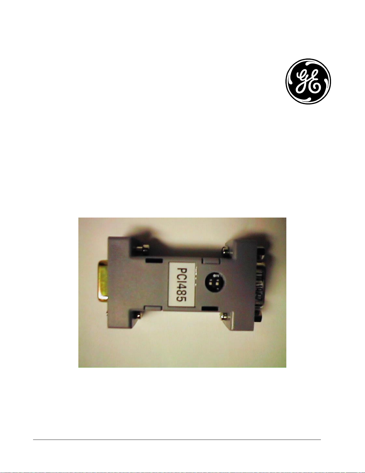
6KCV300CTI
Instruction book
6KCV300CTI - 11/97
1
Page 2

Page 3

1 General
The 6KCV300CTI interface allows the connection of a PC to AV-300, DV-300 and DGF card using the
RS485 port.
GEI-100275
Terminating resistor
Dip-switches
FM
XS2 XS1
Lato PC/
The Interface can be connected directly to the RS232 serial line of the PC, and through a standard
9 pin cable to the XS connector of the Drive or the DGF board.
The interface allows two type of connection:
• Point to Point Connection
• Multidrop connection
PCI-485
PC side
Lato Drive /
Drive side
Point to Point connection
This type of connection can only be used for direct communication of the PC to the Drive and its
options, using software configuration tools designed for this purpose. Do not use 6KCV300CTI for system
control or monitoring. The maximum cable length is of 2 meters from the PC to drive.
The board is powered from by means of the communication line RS 485 through the XS1 connector
with a +5V (±10%) referred to GNDD. The supply is provided by the Drive regulation board or by the DGF
card. See section 6 to properly set jumpers
The Interface converts the RS232 of the full duplex serial line of the PC into the RS485 of the half
duplex serial line of the Drives. The management of the RS485 device is completely automatic and it does not
require any software control.
The Interface has two dip-switches for the insertion or disconnection of the terminating resistors. For
the Point to Point connection these switches must be set in OFF position.
To configurate the 6KCV300CTI Interface as Point to Point, it is necessary to connect it to the Drive through a
standard cable. To do this, connect directly pin to pin all the single wires (9 wires) or at least the pins 3, 4, 5, 7
and 9 (5 wires) of the connectors XS1 (CV300CTI) and XS (Drive or DGF).
6KCV300CTI - 11/97
2
Page 4

GEI-100275
Dip-switches
DRIVE
S12-13 ON / S18-19 B-C
DGFC
XS
S21-22 ON / S23-24 ON
6KCV300CTI
XS1
PCI-485
XS2
RS232
Dip-switches
RS485
OFF
Figure 1.1 Point to point connection
Multidrop connection
This connection is used to connect the PC to a Multidrop line, which connects the RS485 with two or
more Drives and DGF boards. The maximum length of the connection is 600 meters. It is reccomended to
connect the CV300CTI converter as close as possible to the PC and use the RS485 line to cover the remaining
distance required by the connection.
Supply the board through the connector XS1 providing a +5V (±10%) supply referred to GNDD. The
supply must be provided to the XS1.9 (+5V) and XS1.5 (GND) pins.
The interface converts the RS232 of the PC into the RS485 of the Drives. The management of the
RS485 drive, must be carried out by the PC by mean of the RTS∗ command, available on the RS232 serial line
connector. When active, the command RTS∗ enables the RS485 drive for the transmission.
The two dip-switches placed on the interface have the function to insert or disconnect the terminating
resistors of the line, when set as first and last drop of the net. As default the terminating resistors are
disconnected (switches = OFF).
The interface connects directly the command RTS∗ (7) to the signal CTS∗ (8) and the command DTR∗
(4) to the signal DSR∗ (6) of the PC.
The Multidrop configuration is carried out connecting the CV300CTI interface to the Drives or DGF
through a standard cable. The connection requires only the direct connection of pins 3, 5, 7 and 9 (4 wires) of
the two connectors XS1 (6KCV300CTI) and XS (Drive or DGF). For this it is necessary keeping the pin XS1.4
not connected to any signal (Float).
6KCV300CTI - 11/97
3
Page 5

GEI-100275
Figure 1.2 – 1.3 : Example of Multidrop connection
6KCV300CTI - 11/97
4
Page 6

GEI-100275
2 Power required - Cable length – Maximum number of Drops
2.1 +5 VDC Power required
CTI converter 20mA max
Drive (RS485) 60mA max
DGF Card 60mA max
2.2 Cable length
The maximum cable length of the RS485 serial protocol allows is equal to 600 meters.
Using the CV300CTI Interface, no length of the connection cable is determined about the RS232 side
(PC side), and it is required to set the Interface directly to the PC serial output.
2.3 Maximum number of Drops
Each 6KCV300CTI can supply, in Multidrop configuration, a maximum number of 32 devices
Drives/Dgfc.
A properly sized 5V external power supply is required. A rule of thumb would be 2.5 ADC 5 V power
supply for 32 devices.
3 General information
The connection of the command DTR* to the signal DSR* is direct, without electrical interface. The
status of the signal DSR* can be used to verify the PCI-485 Interface connection to the PC.
The connection of the command RTS* to the signal CTS* is performed by mean of an electical interface
RS232. The status of the signal CTS can be used ti verify the connection and the supply of the PCI-485
interface.
4 Blocks diagram
∗
∗
∗
∗
Figure 4.1: Blocks diagram
6KCV300CTI - 11/97
5
Page 7

5 Connectors
5.1 XS1 Connector
Pin
GEI-100275
XS1 Connector
Number
1- - - 2- - - 3 A A RS485 I/ O RS485
4 SEL Multidrop selection I CMOS AC
5GND
6 +5V Power supply I 7 B B RS485 I/ O RS485
8GND
9 +5V Power supply I/O -
Signal Description
0V Power supply
0V Power supply
Table 1: XS1 Connector
Function Electrical protocol
I/O -
I-
5.2 XS2 Connector
XS2 Connector
Pin
Number
Signal Description
Function Electrical protocol
1- - - 2 RX RX RS232 O RS232
3 TX TX RS232 I RS232
4
5GND
6
7
8
9- - - -
DTR∗
DSR∗
RTS∗
CTS∗
DTR RS232 I RS232
0V Power Supply
DSR RS232 O RS232
RTS RS232 I RS232
CTS RS232 O RS232
Table 2: XS2 Connector
I/O -
6 Drives and DGF card configuration for use with 6KCV300CTI Interface
6KCV300CTI - 11/97
6
Page 8

GEI-100275
pply
pply
pply
DV-300
Jumpers name function Default configuration Using 6KCV300CTI
S12/S13 Insertion/disconnection of
S15
the terminating resistor
Insertion/disconnection of
RX channel ON = Inserted ON = Inserted
ON = Inserted
(On the first and the last drop of the
net)
ON = Inserted
S29/S30 Insertion/disconnection of
S18/S19
TX-RX TTL level
Selection internal/external
su
for RS485 interface
A-C Position
External (pin 5-9)
B-C Position (Internal)
OFF
Not Active
A-C Position
(External)
OFF
Not Active
B-C Position
(Internal)
AV-300
Jumpers name function Default configuration Using 6KCV300CTI
S12/S13 Insertion/disconnection of
S15 Insertion/disconnection of
S31/S32 Insertion/disconnection of
S18/S19
the terminating resistor
RX channel
TX-RX TTL level
Selection internal/external
su
for RS485 interface
A-C Position
External (pin 5-9)
ON = Inserted
ON = Inserted ON = Inserted
OFF
Not Active
A-C Position
(External)
ON = Inserted
(On the first and the last drop of
the net)
OFF
Not Active
B-C Position
(Internal)
B-C Position (Internal)
DGF card
Jumpers name function Default configuration Using 6KCV300CTI
S23/S24 Insertion/disconnection of
S25
S26/S27 Insertion/disconnection of
S21/S22
the terminating resistor
Insertion/disconnection of
Selection internal/external
su
OFF Position
External (pin 5-9)
ON Position (Internal)
RX channel ON = Inserted ON = Inserted
TX-RX TTL level
for RS485 interface
6KCV300CTI - 11/97
ON = Inserted
OFF
Not Active
OFF Position
(External)
(On the first and the last drop of
the net)
ON = Inserted
OFF
Not Active
ON Position
(Internal)
7
 Loading...