

Page 1

Logix 764 Operation Manual
Models: 293/298 Magnum IT
Twin Alternating
Twin Parallel
Single with Remote Regeneration Start
Multi-Single Tank with Lockout
Page 2

Page 3

Table of Contents
Table of Contents . . . . . . . . . . . . . . . . . . . . . . . . . . . . . . . . . . . . . . . . . . . . . . . . . . . . . . . . . . . . 1
Safety Information . . . . . . . . . . . . . . . . . . . . . . . . . . . . . . . . . . . . . . . . . . . . . . . . . . . . . . . . . . . 3
Installation Profile Summary . . . . . . . . . . . . . . . . . . . . . . . . . . . . . . . . . . . . . . . . . . . . . . . . . .4
How To Use This Manual . . . . . . . . . . . . . . . . . . . . . . . . . . . . . . . . . . . . . . . . . . . . . . . . . . . . .5
Icons That Appear In This Manual . . . . . . . . . . . . . . . . . . . . . . . . . . . . . . . . . . . . . 5
Location Selection . . . . . . . . . . . . . . . . . . . . . . . . . . . . . . . . . . . . . . . . . . . . . . . . . . . . . . . . . . . 6
Outdoor Locations . . . . . . . . . . . . . . . . . . . . . . . . . . . . . . . . . . . . . . . . . . . . . . . . . . . . . . . . . . . 7
Assembling the Logix 764 Control to the
Magnum Valve . . . . . . . . . . . . . . . . . . . . . . . . . . . . . . . . . . . . . . . . . . . . . . . . . . . . . . 8
Magnum General Specifications . . . . . . . . . . . . . . . . . . . . . . . . . . . . . . . . . . . . . . . . . . . . .12
General Installation Information . . . . . . . . . . . . . . . . . . . . . . . . . . . . . . . . . . . . . . . . . . . . .13
Magnum Valve Installation Guide (Top Mount) . . . . . . . . . . . . . . . . . . . . . . . . 14
Magnum IT Dimensional Specifications . . . . . . . . . . . . . . . . . . . . . . . . . . . . . . . . . . . . . . .15
Typical Installation Drawings . . . . . . . . . . . . . . . . . . . . . . . . . . . . . . . . . . . . . . . .16
Camshaft Cycle Positions . . . . . . . . . . . . . . . . . . . . . . . . . . . . . . . . . . . . . . . . . . . . . . . . . . . .17
764 Control Operation . . . . . . . . . . . . . . . . . . . . . . . . . . . . . . . . . . . . . . . . . . . . . . . . . . . . . . . 17
Power Loss Memory Retention . . . . . . . . . . . . . . . . . . . . . . . . . . . . . . . . . . . . . . 17
Flow Diagrams . . . . . . . . . . . . . . . . . . . . . . . . . . . . . . . . . . . . . . . . . . . . . . . . . . . . . . . . . . . . . .18
Identifying the Logix Control . . . . . . . . . . . . . . . . . . . . . . . . . . . . . . . . . . . . . . . . . . . . . . . . .23
Display Icons & Cursors . . . . . . . . . . . . . . . . . . . . . . . . . . . . . . . . . . . . . . . . . . . . . . . . . . . . .24
Keypad — Buttons . . . . . . . . . . . . . . . . . . . . . . . . . . . . . . . . . . . . . . . . . . . . . . . . . .25
Programming Conventions . . . . . . . . . . . . . . . . . . . . . . . . . . . . . . . . . . . . . . . . . .25
Placing Water Conditioning System Into Operation . . . . . . . . . . . . . . . . . . . . . . . . . . .26
Level l Programming - 764 Control with 298 Valve, 5 Cycle Conditioner . . . . . . . .28
Level l Programming - 764 Control with 293 Valve, 3 Cycle Filter . . . . . . . . . . . . . .29
Placing Water Conditioning System Into Operation (continued) . . . . . . . . . . . . . . . .30
Quick Cycling the Control 293/298A, 293/298P and 293/298L . . . . . . . . .30
In Service Display . . . . . . . . . . . . . . . . . . . . . . . . . . . . . . . . . . . . . . . . . . . . . . . . . . . . . . . . . . .32
Programming Overview . . . . . . . . . . . . . . . . . . . . . . . . . . . . . . . . . . . . . . . . . . . . . 32
Level I Programming . . . . . . . . . . . . . . . . . . . . . . . . . . . . . . . . . . . . . . . . . . . . . . . . 32
Level II Programming – P Values . . . . . . . . . . . . . . . . . . . . . . . . . . . . . . . . . . . . . . . . . . . . .33
Programming the Lockout Feature . . . . . . . . . . . . . . . . . . . . . . . . . . . . . . . . . . . . . . . . . . .34
Salt Setting (298 Conditioner) . . . . . . . . . . . . . . . . . . . . . . . . . . . . . . . . . . . . . . . . . . . . . . . . 34
Level lll Cycle Programming – C Values . . . . . . . . . . . . . . . . . . . . . . . . . . . . . . . . . . . . . . .35
Level IV Viewing History - H Values . . . . . . . . . . . . . . . . . . . . . . . . . . . . . . . . . . . . . . . . . . .36
Program Reset . . . . . . . . . . . . . . . . . . . . . . . . . . . . . . . . . . . . . . . . . . . . . . . . . . . . . . . . . . . . .36
Manual Regeneration Options . . . . . . . . . . . . . . . . . . . . . . . . . . . . . . . . . . . . . . . . . . . . . . .37
Regeneration Modes for Parallel Systems . . . . . . . . . . . . . . . . . . . . . . . . . . . . . . . . . . . .38
Page 4

Wiring Diagrams . . . . . . . . . . . . . . . . . . . . . . . . . . . . . . . . . . . . . . . . . . . . . . . . . . . . . . . . . . . . 39
Connecting the Logix 764 Twin Alternating or Parallel Controls . . . . . . . . 39
Remote Regeneration Start . . . . . . . . . . . . . . . . . . . . . . . . . . . . . . . . . . . . . . . . . 39
Connecting the Logix 764 Multi Single Tank Control . . . . . . . . . . . . . . . . . . 40
Troubleshooting . . . . . . . . . . . . . . . . . . . . . . . . . . . . . . . . . . . . . . . . . . . . . . . . . . . . . . . . . . . . .41
764 Controller – Error Codes & 298 ”L” with Check Salt Light . . . . . . . . . 41
System Troubleshooting . . . . . . . . . . . . . . . . . . . . . . . . . . . . . . . . . . . . . . . . . . . . 42
Magnum Valve Cartridge Troubleshooting . . . . . . . . . . . . . . . . . . . . . . . . . . .44
Magnum Valve Cartridge Removal Procedure . . . . . . . . . . . . . . . . . . . . . . . . . . . . . . . .46
Performance Injectors . . . . . . . . . . . . . . . . . . . . . . . . . . . . . . . . . . . . . . . . . . . . . . . . . . . . . . .47
Injector Charts . . . . . . . . . . . . . . . . . . . . . . . . . . . . . . . . . . . . . . . . . . . . . . . . . . . . . . 47
Magnum Flow Controls . . . . . . . . . . . . . . . . . . . . . . . . . . . . . . . . . . . . . . . . . . . . . . . . . . . . . .49
Refill Control Identification . . . . . . . . . . . . . . . . . . . . . . . . . . . . . . . . . . . . . . . . . .49
Drain Line Flow Control . . . . . . . . . . . . . . . . . . . . . . . . . . . . . . . . . . . . . . . . . . . . .50
Recommended Backwash Flow Rates for Various Media . . . . . . . . . . . . . .51
764 Logix Magnum Exploded View . . . . . . . . . . . . . . . . . . . . . . . . . . . . . . . . . . .52
Replacement Components: Logix Magnum Conditioner/Filters . . . . . . . . . . . . . . . .53
Camshaft and Pilot Valve Assembly . . . . . . . . . . . . . . . . . . . . . . . . . . . . . . . . .53
Magnum Valve Cartridges . . . . . . . . . . . . . . . . . . . . . . . . . . . . . . . . . . . . . . . . . .54
Injector Assembly . . . . . . . . . . . . . . . . . . . . . . . . . . . . . . . . . . . . . . . . . . . . . . . . . . .55
Refill Flow Control Assembly . . . . . . . . . . . . . . . . . . . . . . . . . . . . . . . . . . . . . . . . .56
Magnum IT Flow Sensor Assembly . . . . . . . . . . . . . . . . . . . . . . . . . . . . . . . . . . .57
Installation Adapter Kits . . . . . . . . . . . . . . . . . . . . . . . . . . . . . . . . . . . . . . . . . . . . .58
Miscellaneous Kits and Assemblies . . . . . . . . . . . . . . . . . . . . . . . . . . . . . . . . . .59
Page 5

Safety Information
This water conditioner’s control valve conforms to UL/CE
Standards. Generic valves were tested and certified for
compliance as verified by the agency listing.
• Please review the entire Installation and Operation
Manual before installing the water conditioning
system.
• As with all plumbing projects, it is recommended that
a trained professional water treatment dealer install
the water conditioning system. Please follow all local
plumbing codes for installing this water conditioning
system.
• This system will not make microbiologically unsafe
water safe. Water that is unsafe must be treated
separately from this conditioner.
• This water conditioning system is to be used only for
potable water.
• Inspect the water conditioning system for carrier
shortage or shipping damage before beginning
installation.
• Use only lead-free solder and flux, as required by
federal and state plumbing codes, when installing
soldered copper plumbing.
• Use caution when installing soldered metal piping
near the water conditioning system. Heat can
adversely affect the plastic control valve and bypass
valve.
• All plastic connections should be hand tightened.
1
Teflon
tape may be used on connections that do not
use an O-ring seal. Do not use pipe dope type
sealants on the valve body. Do not use pliers or pipe
wrenches.
• Do not use petroleum-based lubricants such as
Vaseline, oils or hydrocarbon-based lubricants. Use
only 100% silicone lubricants.
• Use only the AC adapter supplied with this water
conditioning system.
• All electrical connections must be completed
according to local codes.
• The power outlet must be grounded
• Install an appropriate grounding strap across the inlet
and outlet piping of the water conditioning system to
ensure that a proper ground is maintained.
• To disconnect power, unplug the AC adapter from its
power source.
• Observe drain line requirements.
• Do not support the weight of the system on the
control valve fittings, plumbing, or the bypass.
• Do not allow this water conditioning system to freeze.
Damage from freezing will void this water
conditioning system’s warranty.
• Operating ambient temperature: 34° to 120°F
(1° to 49°C).
• Operating water temperature: 34° to 100°F
(1° to 38°C).
• Operating water pressure range : 25 to 100 psi (1.72
to 6.89 bar). In Canada the acceptable operating
water pressure range is 25 to 100 psi (1.72 to 6.89
bar).
• Observe all warnings that appear in this manual.
• Keep the media tank in the upright position. Do not
turn upside down or drop. Turning the tank upside
down or laying the tank on its side can cause media
to enter the valve.
• Use only regenerants designed for water
conditioning. Do not use ice melting salt, block salt or
rock salt .
1. Teflon is a trademark of E. I. duPont de Nemours.
3
Page 6
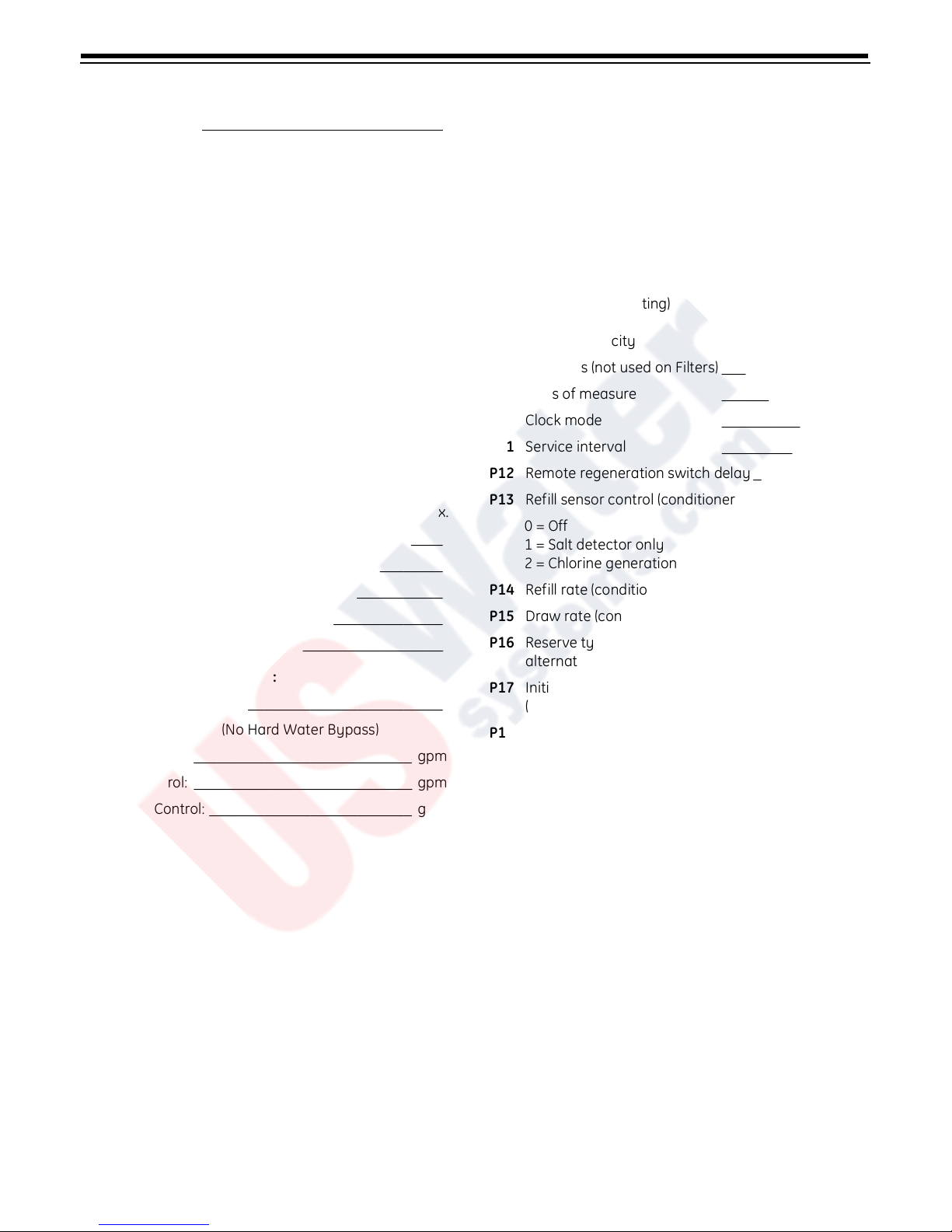
Installation Profile Summary
Installation Date: _______________________________
Installation Location: ____________________________
Installer(s): _____________________________________
Phone Number:_________________________________
Valve Number: _________________________________
Application Type: (Softener) (Filter) (Dealkalizer)
Water Source:
(Public Well) (Private Well)
(Surface Supply)
(Other)
Water Test Results:
Hardness: _______________ Iron:_______________
Other: ________________________________________
Misc:
Capacity:________ Flow Rates: ____ min. ______ max.
Tank Size: Diameter _________ Height: ___________
Resin or Media Volume: __________________________
Resin or Media Type: ____________________________
Brine Tank Volume:______________________________
Salt Setting per Regeneration:_____________________
Control Valve Configuration:
Valve Type: ____________________________________
(Hard Water Bypass) (No Hard Water Bypass)
Refill Control:_______________________________ gpm
Injector Control: ____________________________ gpm
Electronic Demand Settings
P1 Time of day ________________
P2 Day of week ________________
P3 Time of regeneration ________________
P4 Number of days between regeneration (99 day
calendar override) ________________
P6 Amount of regenerant used per regeneration or filter
backwash time (salt setting) ________________
P7 System capacity ________________
P8 Hardness (not used on Filters) ________________
P9 Units of measure ________________
P10 Clock mode ________________
P11 Service interval ________________
P12 Remote regeneration switch delay ____________
P13 Refill sensor control (conditioner only) _________
0 = Off
1 = Salt detector only
2 = Chlorine generation
P14 Refill rate (conditioner only) ________________
P15 Draw rate (conditioner only) ________________
P16 Reserve type (not used for
alternating mode) ________________
P17 Initial average or fixed reserve
(not used for alternating mode)_______________
P18 Flow sensor select ________________
P19 K-factor or pulse equivalent ________________
Backwash Control: __________________________ gpm
4
Page 7
How To Use This Manual
This installation manual is designed to guide the
installer through the process of installing and
starting water conditioning systems featuring the
Logix 764 controller.
This manual is a reference and will not include every
system installation situation. The person installing
this equipment should have:
• Training in the 764 series control and the 298 valve.
• Knowledge of water conditioning and how to
determine proper control settings.
• Adequate plumbing skills.
Icons That Appear In This Manual
WARNING:
can result in personal injury or damage to
the equipment.
Note:
Helpful hint to simplify procedure.
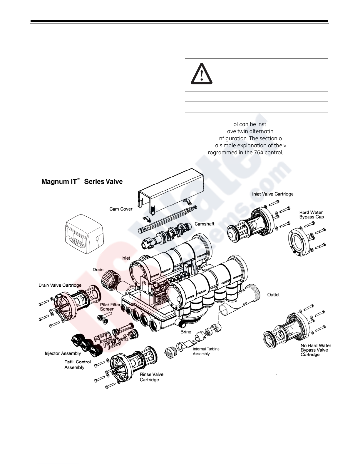
The Logix 764 control can be installed on several type
valves that can have twin alternating, twin parallel or
single tank configuration. The section on Logix 764 startup provides a simple explanation of the valve types that
are pre-programmed in the 764 control.
Failure to follow this instruction
R
Tim
egen Tim
e & D
SU
ay
e & D
Salt Am
MO
ay
TU
ount
WE
C
apacity
TH
H
ardness
Logix 764
FR
SA
DAYS
Figure 1 293/398 Valve Layout
5
Page 8
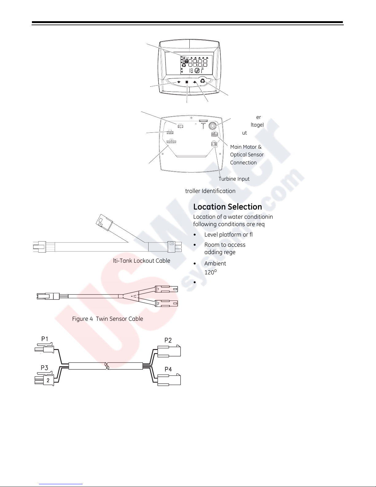
LCD Display
Front
Down Button
No-Salt Detector
(Chlorine Generator)
Connection (not used
on Magnum Valves)
Multi Single Tank
Back
Lockout & Remote
Regen/Start
Dry Contact Signal Input
Connection
Extension Cable
Connection
SU MO TU WE TH FR SA
Time & Day
Regen Time & Day
Salt
Capacity
Hardness
Set Button
x2
P
H
C
PM
MIN
g/L
KG
x100
Lbs/ft³
Up Button
Main Motor &
Optical Sensor
Connection
Turbine Input
Figure 2 764 Controller Identification
Location Selection
Location of a water conditioning system is important. The
following conditions are required:
Manual Regen Button
AC Adapter
(low voltage)
Input
Figure 3 Remote Start/Multi-Tank Lockout Cable
Figure 4 Twin Sensor Cable
Figure 5 Twin Cable Extension
• Level platform or floor.
• Room to access equipment for maintenance and
adding regenerant (salt) to tank.
• Ambient temperatures over 34
o
F (49oC).
120
o
F (1oC) and below
• Water pressure below 100 psi (6.89 bar) and above 25
psi (1.7 bar).
• In Canada the water pressure must be below 100 psi
(6.89 bar).
• Constant electrical supply to operate the controller.
• Total minimum pipe run to water heater of ten feet
(three meters) to prevent backup of hot water into
system.
• Local drain for discharge as close as possible.
• Water line connections with shutoff or bypass valves.
• Must meet any local and state codes for site of
installation.
• Valve is designed for minor plumbing misalignments.
Do not support weight of system on the plumbing.
• Be sure all soldered pipes are fully cooled before
attaching plastic valve to the plumbing.
6
Page 9
Outdoor Locations
When the water conditioning system is installed outdoors,
several items must be considered.
• Moisture – The valve and control are rated for NEMA 3
locations. Falling water should not affect
performance. The system is not designed to
withstand extreme humidity or water spray from
below. Examples are: constant heavy mist, near
corrosive environment, or upwards spray from
sprinkler.
Caution:
used with a listed Class 2 power supply suitable for
outdoor use.
• Direct Sunlight – The materials used will fade or
• Temperature – Extreme hot or cold temperatures will
This unit is for dry location use only unless
discolor over time in direct sunlight. The integrity of
the materials will not degrade to cause system
failures.
cause damage to the valve or control. Freezing
temperatures will freeze the water in the valve. This
will cause physical damage to the internal parts as
well as the plumbing and conditioning resin. High
temperatures will affect the control. The display may
become unreadable but the control should continue
to function. When the temperature returns to normal
operating limits the display will re-appear. A
protective cover should assist with high temperature
applications.
• Insects – The control and valve have been designed
to keep all but the smallest insects out of the critical
areas. Any holes in the top plate can be covered with
duct tape. The top cover should be installed securely
in place.
7
Page 10

Assembling the Logix 764 Control to the
Magnum Valve
The control and the Magnum valve work together as an
integral system to ensure synchronization. Follow the
steps outlined below to install the control on the Magnum
valve.
Slide Camshaft
Slide the camshaft toward the back of the valve by
pressing on the release tab and pulling on the back end of
the camshaft (Figure 8). The front end of the camshaft will
be flush with the mounting plate.
Remove Cam Cover
Remove the cam cover by pressing in on the cover release
tabs (Figure 6). Note the cover locking tab and the slot in
the top plate. When you reassemble the cover, the locking
tab is placed in the slot first and the cover lowered into
position.
Locking Tab and Slot
Cover Release Tabs
Figure 6
Release Tabs
Figure 8
Mount Control
Mount the control onto the valve by sliding the mounting
tabs over the mounting plate. Note that all models of
Magnum controls mount to the valve in the same manner
(Figure 9).
Mounting Tabs
Align Camshaft
The camshaft is keyed and should only be engaged or
disengaged when in the position illustrated (Figure 7). If
the camshaft is not in the proper position, rotate the cam
assembly counterclockwise until the camshaft arrow
aligns with pillow block arrow.
Camshaft Arrow
Pillow Block Arrow
Figure 7
Mounting Plate
Figure 9
Engage Assembly
The camshaft will not rotate by hand when engaged with
the controller. The Logix Magnum controller contains a
motor with gears that drive a socket. The camshaft is
keyed to only properly engage the socket when the Logix
controller is in the treated water (Home) position.
If the camshaft is pulled back and not engaged it can be
rotated counterclockwise. Rotate the camshaft to align
the arrows (Figure 7). If the Logix Magnum controller is not
8
Page 11

in the treated water position, cycling the power will cause
the socket to rotate to that position.
Engage the control by pressing on the release tab and
pushing the camshaft into the control (Figure 10). Do not
force the camshaft. If the camshaft does not slide freely
into the control, check the alignment of the camshaft to
the controller. Ensure it is in the proper position (Figure 7).
The Logix controller moves to the treated water (home)
position when first power is applied.
Release Tab and
Camshaft
Figure 10
To disassemble the control from the valve, reverse the
assembling procedure.
Inlet, Outlet and Drain Connections
The inlet, outlet, and drain connections are designed to
accept a GE Water Technologies supplied CPVC or brass
adapter (Figure 11). The adapters provide a convenient
union for the three connection ports on the valve. In
addition, they incorporate a positive O-ring face seal for
ease of installation and leak free operation. DO NOT
OVERTIGHTEN THE ADAPTERS. As a general guideline,
hand tightening the nut onto the valve is adequate. If
additional tightening is required, never exceed a quarter
turn beyond the hand tight position.
The outlet of the 2-inch Magnum IT has an integrated
turbine. The turbine measures the flow of water through
the outlet. This information is used by the controller to
determine the best time to recycle.
Figure 11
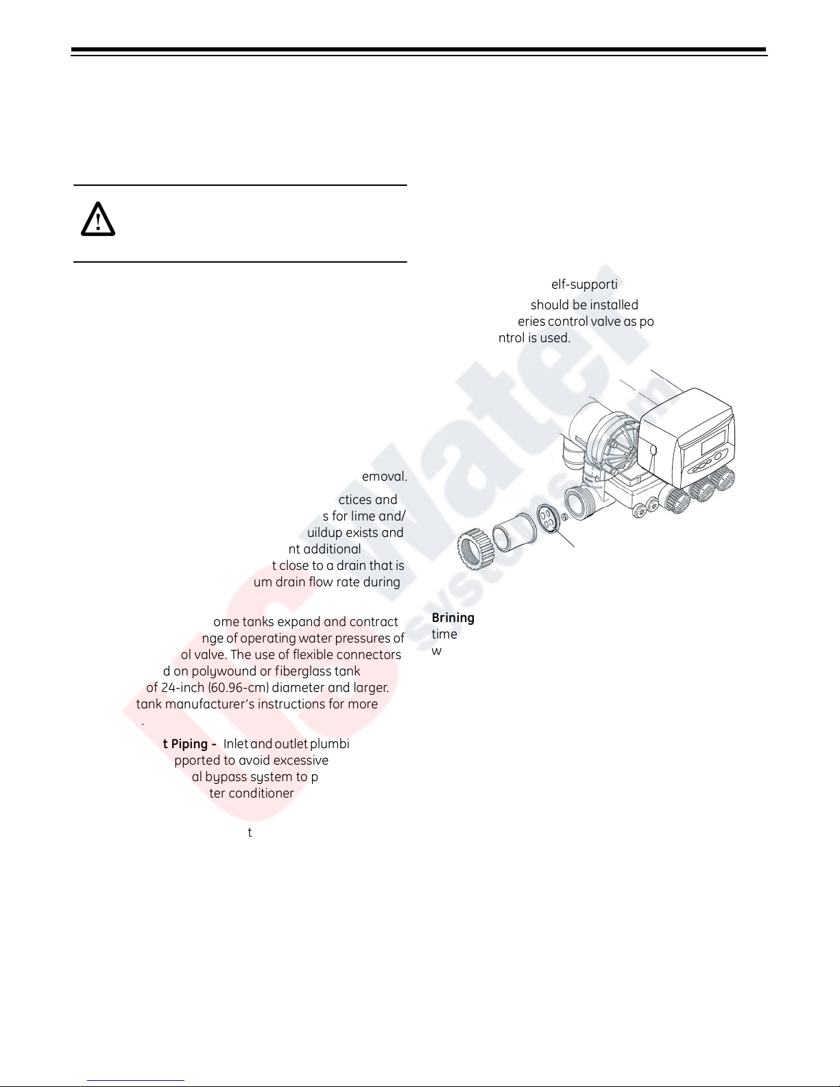
No Hardwater Bypass Feature
The Magnum control valve may be configured for “Hard
Water Bypass” or “No Hard Water Bypass”. With Hard
Water Bypass, unsoftened or unfiltered water is allowed to
bypass the Magnum control valve during regeneration or
backwash. With No Hard Water Bypass, a valve cartridge
ensures that no unsoftened or unfiltered water bypasses
the valve during regeneration or backwash.
It is easy to observe which option is installed in the valve.
Note that the Hard Water Bypass End Cap has much
longer standoffs than the No Hard Water Bypass
cartridge. The No Hard Water Bypass assembly looks
identical to the other three valve cartridges on the valve
and has a label identifying the cartridge assembly (Figure
12).
No Hard Water Bypass
No Unfiltered Water Bypass
Normal Standoffs
Extended Standoffs
With Hard Water Bypass
End Cap
Figure 12
9
Page 12

Hydraulic Output Signal
T
Magnum Tank Adapter
An optional hydraulic output signal is available on the
valve. An optional cam lobe on pilot valve #6 is used on the
camshaft assembly to initiate the hydraulic output signal
during regeneration or backwash (Figure 13). The
hydraulic line pressure signal is available through the
1/4-inch connection on the back of the valve marked
“AUX”. See Figure 14. Remove the tube cap installed for
shipping.
Optional cam lobes available are:
P/N 1000554 Provides a hydraulic signal from the
beginning of BACKWASH through the start
of REFILL.
P/N 1000553 Provides a hydraulic signal from the
beginning of BACKWASH through the end
of REFILL.
P/N 1041064 Breakaway cam. Can be programmed to
send a hydraulic signal at any time during
the REGENERATION or BACKWASH cycle.
Note: The camshaft must be turning for
the signal to change states, i.e. switch
from OFF to ON, or from ON to OFF.
The tank adapter on the control valve is designed to be
compatible with a 4 inch-8UN (8 threads per inch) tank
opening. In addition, the adapter is designed to accept a
full 1-1/2-inch (3.81-cm) riser pipe with outside diameter of
1.90 to 1.91 inches (48.26 to 48.51 mm) (Figure 15). The
riser pipe is sealed by an O-ring on the inside of the tank
adapter (Figure 15). It is recommended that the riser pipe
extend beyond the top of the tank by 1/4 inch ± 3/8 inch (6
mm ± 9 mm).
O-ring
Tank O-ring
op of Tank
.375" (9.52 mm)
Top of Riser
Riser O-ring
O-ring
0.25"
(6.4 mm)
±.375"
(9.5 mm)
Figure 13
Optional Cam
Lobe Position #6
“Hydraulic Output
Signal”
Auxiliary
Hydraulic
Output Port
“AUX”
Figure 15
Optional Switch Assembly
A single optional feedback switch kit is available to provide
an electrical signal during the entire regeneration or
backwash cycle (Figure 16). The switch may be wired in
the “Normally Open” or “Normally Closed” position and is
rated for 0.1 amp at 125 volts AC. An optional 5.0 amp
switch at 1/10 HP 125/250 volts AC is available upon
request.
Common
Normally Open
Figure 14
Normally Closed
Pilot Drain Port
Figure 16
Optional multi-switch kits are available to provide
10
Page 13

additional electrical or switch closure signals during the
regeneration or backwash cycles. Coupled with the
optional breakaway cams, signals can be sent to external
system equipment at virtually any time while the control/
camshaft motor is running. Consult the instruction sheet
covering the multi-switch option for additional application
and programming information. The instruction sheet is
sent with the switch kit.
11
Page 14

Magnum General Specifications
Operating and Environmental
Dynamic Pressure .................................................................................................................................................25 to 100 psig (172 to 688 kPa)
100 psig (688kPa) maximum in Canada
o
Operating Water Temperature Range.......................................................................................................................... 34 to 100
Ambient Temperature Range............................................................................................................................................ 34 to 120
F (1 to 36oC)
o
F (1 to 50oC)
Cap Bolt Torque ............................................................................................................................................... 35 to 40 inch lbs. (3.95 to 4.51 N
m
Connections
Inlet and Outlet ...................................................................................................................... ........................ ......................... .......... 2-inch Magnum IT
Tank....................................................................................................................................................................................................................... 4-inch 8UN
Brine...................................................................................................................................................................................................................3/4-inch NPT
Pilot Drain and Auxiliary Hydraulic Out .............................................................................................................................1/4-inch tube fitting
Riser Pipe Fitting............................................................................................................................................................................ 1-1/2 inch (3.81-cm)
Drain ...................................................................................................................................................................................................1-1/2 inch (3.81-cm)
Physical
Dimensions ...................................................................................................................................................26-11/16" L, 16-1/4" W, 10-11/16" H
Approximate Weight (Valve and Control) ................................................................................................................................23.3 lbs. (10.6 kg.)
Electrical*
Voltage - Logix 764 Series Control..................................................................................................... 12 VAC wall mount transformer only
Power Consumption...............................................................................................................................................................................................4 watts
)
*See section on Electronic Controls for alternative electrical configurations.
12
Page 15
General Installation Information
Please review the following items thoroughly to ensure an
efficient and safe installation of the water treatment
system. The typical installation line drawings for the
Magnum valves are shown in Figure 19.
WARNING:
Filter media may need to be
properly conditioned before the filter is placed
into full operation. Consult the original equipment
manufacturer for proper procedure.
Operating Conditions -
A minimum dynamic
operating water pressure of 25 psig (172 kPa) is
required for the Magnum control valve to operate
properly.
(688 kPa). In Canada, water pressure is not to exceed
100 psig (688 kPa). Water temperature is not to exceed
100
conditions.
Space Requirements - Allow adequate space for the
water treatment system and associated piping. A
minimum of 4 1/2 inches (11.5 cm) front and rear
clearance is required for cartridge assembly and removal.
Plumbing - Always follow good plumbing practices and
conform to local codes. Check existing pipes for lime and/
or iron buildup. Replace piping if heavy buildup exists and
initiate the proper treatment to prevent additional
occurrences. Locate the equipment close to a drain that is
capable of handling the maximum drain flow rate during
backwash.
Flexible Connectors - Some tanks expand and contract
over the acceptable range of operating water pressures of
the Magnum control valve. The use of flexible connectors
is recommended on polywound or fiberglass tank
installations of 24-inch (60.96-cm) diameter and larger.
Follow the tank manufacturer’s instructions for more
information.
Inlet and Outlet Piping - Inlet and outlet plumbing should
be adequately supported to avoid excessive loads on the
valve. Install a manual bypass system to provide for
occasions when the water conditioner must be bypassed
for servicing.
Drain LIne Piping - To prevent mineral loss during
backwash, and to ensure proper operation of the control
valve, A DRAIN LINE FLOW CONTROL must be plumbed
into the drain line prior to placing the valve in the service
mode. Flow controls from 5 to 40 gpm (18.92 to 151.4 Lpm)
are available from GE Water Technologies and can be
easily installed in the drain line. Flow controls greater than
40 gpm (151.4 Lpm) must be plumbed externally. Selection
of the proper drain line flow control depends on the tank
size and media used for the installation.
Water pressure is not to exceed 100 psig
o
F (36oC). Do not subject the valve to freezing
The following general drain line piping guidelines should
be observed:
• 1-1/2 inch (3.81 cm) or larger piping
• Should not exceed 20 feet (6.1 m)
• Should not be elevated higher than f ive feet above the
control valve
• No shut-off valves should be installed in drain line
• Minimal number of elbows and fittings should be
installed in drain line
• Piping must be self-supporting
• Flow control should be installed as close to the
Magnum Series control valve as possible if an external
flow control is used.
DAYS
SUMO TU WE TH FR SA
Time & Day
Salt Amount
Regen Time & Day
Capacity
Hardness
Drain Line Flow Control Disk
Figure 17
Brining System - The Magnum control valve utilizes
timed water refill to add water to the salt tank. A refill tube
with check ball is required in the brine tank that does not
restrict the refill or brine draw flow rate capabilities of the
valve. Although not required, a separate brine valve (safety
float) system is recommended for use with Magnum
installations. Select a “High-Flow” brine valve that does not
restrict the refill or brine draw flow rate capabilities of the
valve. The “Performance Injectors and Magnum Flow
Controls” section of this manual contains flow rate
information for various size injectors and refill controllers.
Pilot Drain - During regeneration, a small amount of
water (200 ml or 1 cup) is discharged from the 1/4-inch
(6.3-mm) tube fitting on the back of the valve marked
DRAIN (Figure 18). To prevent this water from being
discharged to the floor, plumb this connection to a nonpressurized drain or to the brine tank. Do not plug or
apply back pressure to the pilot drain at any time.
Crimping the pilot drain line or installing the line to go up,
which causes backpressure, prevents the diaphragm
cartridges from shifting properly through the cycles of
regeneration or backwash.
13
Page 16

Auxiliary Hydraulic
Output Port - Plugged
Electrical
1. Electrical requirements for the installation depends on
the configuration of the control.
2. The standard North American Series Logix electronic
control is supplied with a 12 volt AC adapter. Optional
AC adapters must be ordered separately for all
international 12 VAC configurations.
Pilot Drain Port
Figure 18
Magnum Valve Installation Guide (Top Mount)
Before the installation of the internal distribution system
and loading of the media into the tank, the Magnum valve
must be temporarily installed onto the tank. This will
ensure that correct alignment of the inlet and outlet piping
once the internals are installed and the media is loaded
onto the tank.
1. Install tank O-ring into the tank adapter section at the
bottom of the Magnum valve. Be sure to lightly
lubricate the O-ring with the 100% silicone lubricant
provided with the valve.
2. Screw the Magnum valve onto the empty tank until
O-ring touches the top of the tank.
3. Turn (tighten) the Magnum valve an additional 60° to
90° (max).
4. Align valve with plumbing connections to minimize
unnecessary stress.
Caution:
The Logix Control and supplied AC adapter are
for dry location use only, unless used with a Listed Class 2
power supply suitable for outdoor use.
Lubricants
It is very important that 100% silicone lubricant is the only
lubricant used for installing the Magnum control valve. Any
other lubricant may cause material degradation and
potential failure of the valve components.
NOTE: Some silicone based lubricants contain
petroleum-based ingredients. If there is a question about
the lubrication that you are using contact the lubricant
manufacturer to be sure the product is 100% silicone.
Caution:
Plumbing cannot be used for electrical
grounding when metal inlet and outlet piping is
connected to a non-metal valve.
Connect the inlet and outlet piping together using a
grounding strap or clamp to establish continuity.
5. For reference, place a mark on the tank beneath the
front center of the Magnum valve.
6. Remove the Magnum valve in preparation for
installation of the internals and media loading.
7. Prior to loading media, make sure the tank alignment
is correct using the mark on the front of the tank.
8. Cut riser 1/4-inch above the top of the tank, plus or
minus 3/8 inch. Place riser inside the tank.
9. Load media following your supplier’s
recommendations.
10. Follow piping recommendations to provide support
and flexibility. Layout piping to accommodate for FRP
tanks and piping dimensional changes and potential
water hammering. Flexible connectors may be
needed.
11. Proper pipe alignment is needed.
Flex connectors are recommended when installing valves
on FRP tanks that are 24 inches or larger in diameter.
14
Page 17

Magnum IT Dimensional Specifications
2-Inch Inlet and Outlet, 1 1/2-Inch Drain
1-11/16
(4.3 cm)
9-3/4
(24.8 cm)
4-7/16
(11.3 cm)
7
(17.8 cm)
16-1/4
(41.3 cm)
4-1/2
(11.4 cm)
13-1/2
(34.2 cm)
9
(22.9 cm)
4-1/2
(11.4 cm)
6-1/2
(16.5 cm)
2-15/16
(7.5 cm)
7-1/2
(19 cm)
11-3/4
(29.9 cm)
13-15/16
(35.5 cm)
1-1/16
(2.7 cm)
15-7/16
(39.2 cm)
26-11/16
(67.8 cm)
4-7/16
(11.3 cm)
15
Page 18

Typical Installation Drawings
Twin Tank
Multiple Tank
Figure 19
16
Page 19

Camshaft Cycle Positions
764 Control Operation
The front end of the camshaft has an indicator cup. The
cup has slots in the outer edge and cycle numbers on the
inside face.
Remove the cover and look over the top of the 764 control
to view the cycle numbers. The number in the opening,
(Figure 20) indicates the current cycle position of the
control valve. The corresponding slot for the number is
positioned at the optical sensor, which is rotated
approximately 90 degrees out of phase.
Cycle Indicators:
0 = Treated Water
1 = Backwash Cycle
2 = Regenerant Draw Cycle
3 = Slow Rinse Cycle
5 = Fast Rinse Cycle
8 = Regenerant Refill Cycle
Number of Current
Cycle
Power Loss Memory Retention
The 764 control features battery-free Time of Day and Day
of Week retention during loss of power. A super capacitor
is designed to keep time for 8 to 24 hours depending on
the installation. If the super capacitor is exhausted the
Logix control will display four dashes
(- - :- -) immediately upon power up. The Time of Day and
Day of Week must be reset.
All other programmed parameters are stored in the static
memory and are retained.
Figure 20 View with Cover and Logix Control Removed
17
Page 20

Flow Diagrams
The Magnum control valve utilizes a series of pilot valves to
properly position the diaphragm valve cartridges (Figure
21). The pilot valves are activated by the camshaft (Figure
22). The flow diagrams that follow represent the Service
Cycle for a 5-cycle conditioner and
Spring
Figure 21 Pilot Valve Principle of Operation, Front View
3-cycle filter configuration. Both the Hardwater Bypass
and No Hardwater Bypass service flow diagrams are
presented.
Spring
Front
Back
Figure 22 Cam Assembly
18
Page 21

Brine
S
ervi
c
e
C
y
c
le
Tank
Refill
Control
Pilot
B1B2
Valves
Injector
Screen
Pilot
Screen
654321B2B1
OPEN OPEN OPENCLSD CLSDCLSDCLSD
CLSD
OPEN OPEN CLSDCLSDOPEN CLSD CLSD
CLSD
OPEN OPEN
OPENOPENOPEN CLSD CLSD
CLSD
CLSDCLSD
OPEN OPEN OPEN OPENCLSD
CLSD
OPEN OPENCLSD OPEN OPENOPEN
CLSD CLSD
Service Cycle
2
12
3
4
56
Injector
Untreated
Water
Treated
Water
Backwash
Water
Regenerant
Service
Backwash
Brine/Slow Rinse
Fast Rinse
Refill/Service
1
Drain
Outlet
Magnum 5-Cycle Conditioner Hard Water Bypass
Bypass
Hard Water
3
Tank Bottom
Pilot Drain
Aux. Pilot
Output
Figure 23
19
Inlet
4
Resin Tank
Tank Top
Page 22

Brine
S
ervi
c
e
C
y
c
le
Tank
Refill
Control
Pilot
B1B2
Valves
Injector
Screen
Pilot
Screen
654321B2B1
OPEN OPEN OPENCLSD CLSDCLSDCLSD
CLSD
OPEN OPEN CLSDCLSDOPEN CLSD CLSD
CLSD
OPEN OPEN
OPENOPENOPEN CLSD CLSD
CLSD
CLSDCLSD
OPEN OPEN OPEN OPENCLSD
CLSD
OPEN OPENCLSD OPEN OPENOPEN
CLSD CLSD
Service Cycle
2
12
3
4
56
Injector
Untreated
Water
Treated
Water
Backwash
Water
Regenerant
Service
Backwash
Brine/Slow Rinse
Fast Rinse
Refill/Service
1
Drain
Outlet
Magnum 5-Cycle Conditioner No Hard Water Bypass
No Hard
Water Bypass
3
Tank Bottom
Pilot Drain
Aux. Pilot
Output
Figure 24
20
Inlet
4
Resin Tank
Tank Top
Page 23

Pilot
B1B2
Valves
Pilot
Screen
654321B2B1
OPEN OPEN OPENCLSD CLSDCLSDCLSD
CLSD
OPEN OPEN CLSDCLSDOPEN CLSD CLSD
CLSD
CLSDCLSDOPEN OPEN OPEN OPENCLSD
CLSD
Service Cycle
2
12
Untreated
Water
Treated
Water
Backwash
Water
Regenerant
Plugged Injector
3
4
56
Service
Backwash
Fast Rinse
1
Drain
Magnum 3-Cycle Filter: Unfiltered Water Bypass
Outlet
Unfiltered
Water Bypass
3
Tank Bottom
Aux. Pilot
Pilot Drain
Output
Figure 25
21
Inlet
4
Media Tank
Tank Top
Page 24

Pilot
B1B2
Valves
Pilot
Screen
654321B2B1
OPEN OPEN OPENCLSD CLSDCLSDCLSD
CLSD
OPEN OPEN CLSDCLSDOPEN CLSD CLSD
CLSD
CLSDCLSDOPEN OPEN OPEN OPENCLSD
CLSD
Service Cycle
2
12
Untreated
Water
Treated
Water
Backwash
Water
Regenerant
Plugged Injector
3
4
56
Service
Backwash
Fast Rinse
1
Drain
Outlet
Magnum 3-Cycle Filter: No Unfiltered Water Bypass
No Unfiltered
Water Bypass
3
Tank Bottom
Aux. Pilot
Pilot Drain
Output
Figure 26
22
Inlet
4
Media Tank
Tank Top
Page 25

Identifying the Logix Control
If you are unsure of your control model, simply remove
the cover and disconnect the controller module from the
control valve. On the back of the control valve is a silver
label that shows your model number and version revision.
Model number: 764
GE Infrastructure
Milwaukee, WI USA
Autotrol Brand
Model 764
12 V/ 60 Hz/ 4W
VERSION 1.02
WO#4340000
Ser. No: 764090052683-3
GE Infrastructure
Milwaukee, WI USA
Autotrol Brand
Model Magnum/764
12 V/ 60 Hz/ 4W
VERSION 1.02
WO#4340000
Ser. No: MAG058070634
Serial number with date code
Figure 27
Figure 28
How To Read the Serial Number
Ser. No. MAG 058 07 0634
Model
Day of
the Year
Year Unit Number
Figure 29
23
Page 26

Display Icons & Cursors
16
8
10
7
9
2
13
14
a
Time/Day
Regeneration Time
15
Salt Amount
SU MO TU WE TH
12
13
26
Capacity
a
Hardness
C
H
25
23
22
Note:
24
In normal operation and during programming,
only a few of the icons are actually displayed.
1. This cursor is displayed when the days between
regeneration are being programmed (used with .5 to
99 day regeneration programming).
2. One of these cursors is displayed to indicate which
day will be programmed into the controller.
3. "PM" indicates that the time displayed is between
12:00 noon and 12:00 midnight (there is no AM
indicator). PM indicator is not used if clock mode is set
to 24-hour.
4. When "MIN" is displayed, the value entered is in
minute increments.
5. When g/L is displayed, the value for regenerant
amount entered is in grams/Liter.
6. When "Kg" is displayed, the value entered is in
kilograms or kilograins.
7. Four digits used to display the time or program value.
Also used for error codes.
8. Colon flashes as part of the time display. Indicates
normal operation (742 only).
9. Locked/unlocked indicator. In Level I programming
this is displayed when the current parameter is
locked-out. It is also used in Level II programming to
indicate if the displayed parameter is locked (icon
flashes) when controller is in Level I.
FR
SA DAYS
PM
MIN
g/L
KGx2
x100P
3
Lbs/ft
6
17
1
3
4
5
a
If your Logix 764 controller was
purchased as a filter control, the
overlay will show: Time/Day,
Backwash Time, Backwash Length
and Capacity.
18
19
21
20
11. The recycle sign is displayed (flashing) when a
regeneration at the next time of regeneration has
been called for. Also displayed (continuous) when in
regeneration.
12. The display cursor is next to "SALT AMOUNT" when
programming the amount of regenerant. If the
controller is on a 3-cycle filter then backwash time is
programmed.
13. The display cursor is next to "REGENERATION TIME"
when programming the time of regeneration and the
days of regeneration.
14. The display cursor is next to "TIME/DAY" when
programming the current time and day.
15. The hourglass is displayed when the motor is running.
The camshaft should be turning.
16. These cursors appear next to the item that is
currently displayed.
17. X100 multiplier for large values.
18. When Lbs/ft
3
is displayed the value for regenerant
amount entered is in pounds/cubic foot.
19. Faucet is displayed when the current flow rate is
displayed. Control may show the faucet and "0",
indicating no flow.
20. Maintenance interval display turns on if the months
in service exceed the value programmed in P11.
21. Used with #24, #25, and #26. Displays valve in
service, a sequence number or a value.
10. When "x2" is displayed, a second regeneration has
been called for.
22. History Values (H). The number displayed by #23
identifies which history value is currently displayed.
24
Page 27

23. Parameter (P). Displayed only in Level II Programming.
The number displayed by #23 identifies which
parameter is currently displayed.
24. Cycle (C). The number displayed by #23 is the current
cycle in the regeneration sequence.
25. Hardness setting—only used with 298 conditioners.
26. Capacity display—shows estimated system capacity.
Keypad — Buttons
1
2
Figure 30
3
4
Programming Conventions
The 700 series controller is programmed using the
buttons on the keypad. The programming instructions are
described two ways whenever a section has keypad
input.
First, a table shows simplified instructions. Second, text
follows that describes the action. In each table:
"Action" lists the event or action desired.
"Keys" are listed as:
UP for up arrow
DOWN for down arrow
SET for set
REGEN for regeneration
"Duration" describes how long a button is held down:
P/R for press and release
HOLD for press and hold
X sec for a number of seconds to press the button
and hold it down
"Display" calls out the display icons that are visible.
1. DOWN arrow. Generally used to scroll down or incre-
ment through a group of choices.
2. SET. Used to accept a setting that normally becomes
stored in memory. Also used together with the arrow
buttons.
3. UP arrow. Generally used to scroll up or increment
through a group of choices.
4. Regenerate. Used to command the controller to
regenerate. Also used to change the lock mode.
Note:
If a button is not pushed for thirty seconds,
the controller returns to normal operation mode.
Pushing the Regenerate button immediately returns
the controller to normal operation.
25
Page 28

Placing Water Conditioning System Into Operation
After you have performed the installation steps, the
conditioner will need to be placed into operation.
Follow these steps carefully, (pages 26 to 31) as they
differ from previous Autotrol valve instructions.
Note:
(treated water) position. Check to see that the camshaft
is aligned to service position. See Figure 7 on page 8 for
proper control/camshaft alignment.
The incoming supply water should be turned off.
Remove air from tank(s).
Table 1 Preprogrammed Valves
All Logix 764 controls will be shipped in the service
1. Position the bypass valve(s) to the in service (not in
bypass) position.
2. Open the nearest water faucet completely.
3. Open the incoming water supply valve slowly to the
Type Valve
255 A 255
273 A 273 3-cycle filter 1
278 A 278 5-cycle conditioner 1
293 A 293 3-cycle filter 2
298 A 298 5-cycle conditioner 2
255 P 255
273 P 273 3-cycle filter 1
278 P 278 5-cycle conditioner 1
293 P 293 3-cycle filter 2
298 P 298 5-cycle conditioner 2
255 L 255
273 L 273 3-cycle filter 1
278 L 278 5-cycle conditioner 1
293 L 293 3-cycle filter 2
298 L 298 5-cycle conditioner 2
Single Tank Remote Regeneration or
Multi-Single Tank Lockout
Twin Alternating
Twin Parallel
quarter open position.
Note:
tank(s) will fill with water. The air will exit through the
faucet. When water flows steady from the faucet, the
tank(s) are purged.
Power-up the Control
Do not plug in the power supply until step 5. The
4. Turn off the faucet then turn off the incoming water
supply.
5. Plug the AC adapter into a non-switched outlet. The
display will show the valve type that was loaded from
memory.
If this is the first time the control is powered up the
display will show 255A.
6. Use the or buttons to increment
through the available selections, Table 1.
8-cycle conditioner 3/4
8-cycle conditioner 3/4
8-cycle conditioner 3/4
Connection -
inches
For the next steps you may want to remove the cover to
watch the camshaft movement.
7. Press to enter the valve type and the proper
preprogrammed valves for your application:
293A for Twin Alternating Filter
298A for Twin Alternating Conditioner
293P for Twin Parallel Filter
298P for Twin Parallel Conditioner
293L for single or multiple tank filters with regener-
ation lockout or remote regeneration start
298L for single or multiple tank conditioners with
regeneration lockout or remote regeneration
start
Note:
whether a filter or conditioner Logix control was
purchased. If a filter control is programmed to be a
conditioner then the overlay will not be correct. However,
the Logix control will function properly. See previous page
for overlay text.
26
The control overlay changes depending on
8. The display will show
“F” for filter set-up. If a number or an “F” is displayed
then the resin volume or filter type has been
preprogrammed, Table 2.
Finish programming the Logix 764 control using the
Level I programming guide.
---. Select media volume or
Page 29

For a 293/298A system: the control will automatically
syncronize the cam positions.
Tank 1 will move to standby
Tank 2 will move to service
err# will be displayed when the Tank 1 cam is
moving.
cam is moving.
For a 293/298P system:
Tanks 1 and 2 will move to service if not already in
service.
For a 293/298L system:
The tank(s) will move to service if not already in
service.
These cam movements may take up to 5 minutes.
err4 will be displayed when Tank 2
Table 2
Resin Volume - 1.0 ft
Tank Dia
(inches)
14 14 3.00 75
14 14 100
16 16 4.00 125
18 18 5.00 150
21 21 6.00 175
21 21 7.00 200
21 21 8.00 225
24 24 9.00 250
24 24 10.00 275
24 24 300
24 24 11.00 325
Injector US Metric
3
and 25 Liter Steps
Resin Volume
30 30 12.00 350
30 30 13.00 375
30 30 14.00 400
30 30 15.00 425
30 30 16.00 450
30 30 17.00 475
30 30 500
36 36 18.00 525
36 36 19.00 550
36 36 20.00 575
36 36 600
36 36 625
36 36 650
36 36 675
36 36 700
27
Page 30

Level l Programming - 764 Control with 298 Valve, 5 Cycle Conditioner
Screen Buttons to Description Range
Press
SU MO TU WE TH FR SA DAYS
Time/Day
Regeneration Time
Salt Amount
Capacity
Hardness
Time/Day
Regeneration Time
Salt Amount
Capacity
Hardness
Time/Day
Regeneration Time
Salt Amount
Capacity
Hardness
Time/Day
Regeneration Time
Salt Amount
Capacity
Hardness
Time/Day
Regeneration Time
Salt Amount
Capacity
Hardness
Time/Day
Regeneration Time
Salt Amount
Capacity
Hardness
Time/Day
Regeneration Time
Salt Amount
Capacity
Hardness
Time/Day
Regeneration Time
Salt Amount
Capacity
Hardness
SU MO TU WE TH FR SA DAYS
SU MO TU WE TH FR SA DAYS
SU MO TU WE TH FR SA DAYS
SU MO TU WE TH FR SA DAYS
SU MO TU WE TH FR SA DAYS
SU MO TU WE TH FR SA DAYS
SU MO TU WE TH FR SA DAYS
PM
Lbs/ft
KG
then
press
press
then
press
press
then
press
press
then
press
press
then
press
press
then
3
press
press
to override
press
then
press
or
1. Resin Volume
Select correct resin volume
Cubic feet: 3.00
to
20.00
2. Time of Day (12 hr.)
or
Set to time of day
Note: Setting includes PM indicator.
or
3. Day of Week
Set to actual day of the week
4. Time of Regeneration
or
Set to desired time of regeneration
5. Days Override
Leave at 0 to disable
or
or
Set to desired days between
to
99
regeneration
or
Set to desired desired dosage
6. Salt Dosage
Lbs/f
lbs per cubic feet of resin
press
then
or
7. Capacity
Capacity calculated by Logix Control
Use to OVERRIDE calculated capacity
press
8. Hardness
or
Set to actual water hardness
Kilograins:
Grains/gal: 3
in grains per gallon
Days:0
3
:
t
3
to
18
1
to
900
to
200
Control programming is complete
Note:
If one of the following conditions occur:
– control displays Err3 and goes to home position or
– power outage discharges the supercapacitor and when power is restored the time of day is reset;
the Regen Icon will begin flashing. This indicates that a delayed regeneration will occur at the next programmed time of
regeneration. If a delayed regeneration is not desired, press the REGEN Button to disable the delayed regeneration and
the system will regenerate by water usage.
28
Page 31

Level l Programming - 764 Control with 293 Valve, 3 Cycle Filter
Screen Buttons to Description Range
Press
SU MO TU WE TH FR SA DAYS
Time/Day
Backwash Time
Backwash Length
Capacity
Time/Day
Backwash Time
Backwash Length
Capacity
Time/Day
Backwash Time
Backwash Length
Capacity
Time/Day
Backwash Time
Backwash Length
Capacity
Time/Day
Backwash Time
Backwash Length
Capacity
Time/Day
Backwash Time
Backwash Length
Capacity
Time/Day
Backwash Time
Backwash Length
Capacity
SU MO TU WE TH FR SA DAYS
SU MO TU WE TH FR SA DAYS
SU MO TU WE TH FR SA DAYS
SU MO TU WE TH FR SA DAYS
SU MO TU WE TH FR SA DAYS
SU MO TU WE TH FR SA DAYS
Lbs/ft
X100
PM
3
then
press
press
then
press
press
then
press
press
then
press
press
then
press
press
then
press
press
to override
or
1. Program
Type
Select "F"
2. Time of Day (12 hr.)
or
Set to time of day
Note: Setting includes PM indicator.
or
3. Day of Week
Set to actual day of the week
4. Time of Backwash
or
Set to desired time of Backwash
Note: Time of Backwash is not used for Alternating mode.
5. Days Override
Leave at 0 to disable
or
or
Set to desired days between
regeneration
6. Backwash Length (minutes)
or
Set to desired Backwash length
press
then
press
or
7. Capacity (gallons)
Set to desired Capacity in
multiples of 100 gallons
Days:0
to
99
Minutes: 0
to
200
Gallons:
to
900
1
Control programming is complete
Note:
If one of the following conditions occur:
– control displays Err3 and goes to home position or
– power outage discharges the supercapacitor and when power is restored the time of day is reset;
the Regen Icon will begin flashing. This indicates that a delayed regeneration will occur at the next programmed time of
regeneration. If a delayed regeneration is not desired, press the REGEN Button to disable the delayed regeneration and
the system will regenerate by water usage.
29
Page 32

Placing Water Conditioning System Into
Operation (continued)
Note:
have one Logix 764 control that is mounted on tank 1.
Tank 2 has a blank faceplate and the valve is controlled
by the Logix 764 control on tank 1.
293/298 Alternating and parallel tank systems
4. Add water to the regenerant tank.
A. With a bucket or hose add approximately 4
gallons (15 liters) of water to the regenerant
tank.
B. If the tank has a salt platform in the bottom of
the tank, add water until the water level is
approximately 1 inch (25 mm) above the
platform.
Quick Cycling the Control 293/298A, 293/298P
and 293/298L
It is required that the control be quick cycled to specific
regeneration cycles when placing the conditioner into
operation. This will ensure that all of the air in the tank and
valve is purged. The process also provides a check for leaks
and functioning of the brine system. Please perform the
following steps for quick cycling the control, before
proceeding to start-up.
1. With the control in the treated water position, Press and
hold the REGEN button on the controller for 5 seconds.
This will initiate a manual regeneration. The control will
display a solid hourglass indicating that the motor and
camshaft are turning to the backwash cycle (C1). When
the control reaches the backwash cycle, the total
regeneration time remaining will be displayed. Pressing
the SET button will display the specific cycle time
remaining.
2. Press and release the UP and SET buttons to move the
control to the Regenerant Draw cycle (C2).
3. Repeat Step 2 to advance to each cycle.
Before the final filling of the media tank with water
check that:
– the nearest water faucet is completely closed.
– the valve drain line is properly routed to a drain
– the regenerant tank is empty and the regenerant
hose is connected to the valve
– the water supply valve is off.
Note:
treated water position from any regeneration cycle. Press
the UP and SET buttons (about 5 seconds) until the
hourglass icon begins flashing. The control will now skip
all remaining regeneration cycles.
The control can be sent directly back to the
Note:
into the tank until after the control valve has been put into
operation. With no regenerant in the tank, it is much
easier to view water flow and motion in the tank.
It’s recommended that you do not put regenerant
5. Press and hold the button on the controller for 5
seconds. This will initiate a manual regeneration.
The control will display a solid hourglass indicating
that the motor and camshaft are turning to the
backwash cycle (C1). When the control reaches the
backwash cycle, the total regeneration time
remaining will be displayed. Pressing the SET button
will display the specific cycle time remaining.
6. While the controller is in cycle C1 (Backwash), open
the water supply valve very slowly to approximately
the ¼ open position. Water will begin to enter the
media tank. Any air remaining will begin to be purged
to drain as the media tank fills with water.
WARNING:
media may be lost out of the tank into the valve or
the plumbing. In the ¼ open position, you should
hear air slowly escaping from the valve drain line.
When all of the air has been purged from the media
tank (water begins to flow steadily from the drain
line), open the main supply valve all of the way. This
will purge the final air from the tank.
Allow water to run to drain until the water runs clear
from the drain line. This purges any debris from the
media bed.
7. Check Regenerant Draw.
A. Quick cycle the control to the C2 regenerant
draw/slow rinse position .
B. C2 will be displayed. W ith the control in this
position, check to see that the water is being
drawn out of the regenerant tank. The water
level in the regenerant tank should recede
very slowly.
C. Observe that water is being drawn from the
regenerant tank for at least three minutes. If
the water level does not recede, check all
regenerant line connections for air leaks.
If opened too rapidly or too far,
30
Page 33

8. If the water level is receding from the regenerant tank
you can quick cycle the control to the C8 Regenerant
tank refill position.
A. The control will cycle to the regenerant tank
refill cycle, and water will be directed down
through the regenerant line to the regenerant
tank. Let the water flow through the line until
all air bubbles have been purged from the
line. Note: Do not let the water flow down the
line to the tank for more than one to two
minutes, or the tank may overfill.
9. Repeat steps 4 and 8 for each additional tank.
10. Finally, turn on a faucet plumbed after the water
conditioner. Run the faucet until the water runs clear.
11. Add the appropriate amount of regenerant to
regenerant tank.
The Water Conditioning System is Now
Fully Operational
Note:
change, etc.) it is necessary to initiate a manual
regeneration and quick cycle through it. This will ensure
the control and cam are synchronized. If not synchronized
After any control reset (valve type or system
err# will display and the control will drive cams to the
correct position for valve and system type programmed..
31
Page 34

In Service Display
Time/Day
Regeneration Time
Salt Amount
Capacity
Hardness
SU MO TU WE TH FR SA DAYS
Level I Used to program control for normal applications.
Level II (P-Values) Allows the installer to customize
programming for non-standard applications.
Level Ill (C-Values) Allows the installer to adjust the length
of select cycles for non-standard applications.
Level IV History (H-Values) Allows access to historical
information for troubleshooting the system.
Time/Day
SU MO TU WE TH FR SA DAYS
Regeneration Time
Salt Amount
Capacity
Hardness
Logix 764 Electronic Multi-Tank - "A" Alternating
Control:
Service display — The number of the Tank in Service (small
digit next to CPH position) and Alternating Capacity
Remaining and Flow Rate with Faucet icon of Tank in
Service
Logix 764 Electronic Multi Tank - "P" Parallel Control:
Service Display — alternating three items
Capacity remaining for Tank 1 with digit "1" displayed
Capacity remaining for Tank 2 with digit "2" displayed
System Flow Rate (Tank 1 + Tank 2 added) with
Faucet icon
Logix 764 Electronic Multi Tank — "L" Lock Out Control
Service Display — Alternating Capacity Remaining and
Flow Rate with Faucet icon "L” displayed indicating lockout
signal is active. Blinking "L" and Lock icon if lockout signal
is active and control is ready to perform regeneration.
Note:
If a button is not pushed for thirty seconds, the
control returns to normal operation mode.
Level I Programming
The 764 control can be quickly programmed by
following the sequential procedure in the section
“Placing Water Conditioning System Into Operation”.
Level I program parameters are those that can be
accessed by pressing the UP or DOWN buttons.
• Resin Volume Setting: Set to match the volume (cubic
feet) of resin in the mineral tank.
• Time of Day: Includes PM indicator. Can be set to
display as a 24-hour clock. See Level ll programming
• Day of Week: Set to actual day of the week.
• Time of Regeneration: Fully adjustable. Default is
2:00 AM.
• Days Override: Range 0.5 to 99 days. Leave at 0 to
disable.
• Salt Dosage: Set at pounds of salt per cubic foot of
resin in the conditioner tank (298 conditioner only).
For the 293 filter valve the salt dosage is replaced
with backwash length. The display arrow will point to
backwash length and the setting is minutes of backwash.
Note:
The faucet icon is displayed on all the Logix 764
controls when there is flow. The 764 will show the faucet
icon when the flow rate is displayed, even if the flow rate
is zero. If the flow rate is zero, the faucet will turn off when
the capacity is displayed.
Programming Overview
The 764 control includes multiple program levels that allow
the Water Treatment Professional to customize the
system for many water conditions. Additionally, historical
data can be viewed allowing quick and easy
troubleshooting. In most cases Level I programming is all
that is required to set up the water conditioning system for
proper operation. A brief description of each program level
is listed below.
Note:
When the control is set up for a twelve-hour clock
a PM indicator will illuminate when the displayed time is in
the PM hours. There is no AM indicator.
32
Page 35

Level II Programming – P Values
Level II program parameters can be adjusted to fine-tune
the conditioner’s operation. The parameters are
accessible by pressing and holding the UP and DOWN
buttons until the control displays a “P” value. Note: The
control must be in the home position to change settings.
See Table below for Level ll parameters. Typically the Level
ll parameters will not need to be adjusted as the default
settings accommodate most applications. Contact your
Water Treatment Professional before attempting any
programming.
Description Range
P9 Units of Measure 0-1 1 (2) 0 = US 1 = Metric
P10 Clock Mode 0-1 1 (2) 0 = 12 Hr 1 = 24 Hr
P11 Service Interval 0-250 1 0 Months Uses 30 days for each month; 0 = off
Remote
P12
regeneration
switch delay
Chlorine Generator
Options
P13*
(not used on
Magnum systems)
P14* Refill Rate 1-700 1 (1) gpm x 100
P15* Draw Rate 1-700 1 (1) gpm x 100
Reserve Type
P16
(not used for
alternating mode)
Initial average or
fixed reserve
P17
(not used for
alternating mode)
P18 Flow sensor select 0-5 1 (1)
K-factor or Pulse
P19
equivalent
Notes: (1) Default selected with valve type and resin volume.
(2) Factory Default is "0” for North America units and "1” for World units.
3-250 1 60 seconds
0-2 1 0
0-3 1 0
0-70 1 30
1.00-
99.99
0-9999
Minimum
Increments
0.01
1
Default Units Notes
Time remote switch must be active
to start regeneration.
0 = No chlorine generator
1 = salt check only
2 = generate chlorine
0 = variable reserve delayed
regeneration
1 = fixed reserve delayed
regeneration
2 = variable reserve immediate
regeneration
3 = fixed reserve immediate
regeneration
% of
Capacity
0.01
1
Depends on value entered in P16
0 = internal magnum NHWB,
1=1" turbine
2 = 2" turbine
3 = User defined K-factor
4 = User defined pulse equivalent
5 = Internal Magnum HWB
K-factor P18=3;
Pulse Equivalent P18 = 4
*Not used for Magnum valves.
33
Page 36

Programming the Lockout Feature
All Level I parameters can be locked out when the control
is in Level ll programming. Simply press the REGEN button
during Level ll programming and a Lock Icon will appear
indicating that the specific setting has been locked out.
When locked out , the setting cannot be adjusted. To
disable the Lock Out Feature, press the REGEN button
when in Level ll. The lock icon will not be displayed.
Salt Setting (298 Conditioner)
The default P6 salt setting is set at 9 lbs/cu ft. Under
normal circumstances this setting will provide the correct
system capacity. This setting may be adjusted to change
the exchange capacity.
Table 3 Standard Efficiency Exchange Capacity
Salt
lbs/cu ft
3 12714 50 29.9
4 15495 60 34.0
5 17774 70 37.5
6 19661 80 40.6
7 21250 90 43.4
8 22618 100 45.9
9 23828 110 48.2
10 24930 120 50.2
11 25962 130 52.1
12 26950 140 53.8
13 27916 150 55.5
14 28873 170 58.5
15 29829 200 62.7
16 30796 230 66.9
17 31783 260 71.0
18 32806 290 75.3
Exchange
Capacity
grains/cu ft
Salt
grams/
liter
Exchange
Capacity
grams/
liter
34
Page 37

Level lll Cycle Programming – C Values
Several Level III program parameters can be adjusted to
fine-tune a conditioners operation for non-standard
applications. Typically these parameters will not need to
be adjusted as the default settings accommodate most
applications. Contact your Water Treatment Professional
before attempting any programming. The parameters are
accessible by pressing and holding the UP and SET buttons
until the display shows a “C” value.
Note:
The control must by in the treated water position
to change settings.
C# Description Range
Minimum
Increments
C1 Backwash 0 – 200 1 Min 14
C2 Regenerant Draw 0 – 200
a
1 Min See Notes
C3 Slow Rinse 0 – 200 1 Min See Notes
Default
Setting
Notes
Flow rate dictated by size of drain line flow
controller
Automatically calculated from resin volume
and salt dosage settings
Automatically calculated from resin volume
and salt dosage settings
C5 Fast Rinse 0 – 200 1 Min 6 Rinses residual regenerant from tank
C8 Regenerant Refill 0 – 200
a. Only adjustable when the 293 filter valve has been selected.
a
1 Min See Notes
Automatically calculated from resin volume
and salt dosage settings
35
Page 38

Level IV Viewing History - H Values
Historical information can be viewed by pressing the SET
and DOWN buttons simultaneously, with the 764 control in
the home position. Release both buttons when the control
displays an “H” value. Press the UP or DOWN buttons to
navigate to each setting.
Table 4 History Data
H# Description Range Notes
a
H0
Initial Setting Value Cubic Feet or Liters Resin Volume
H1 Days since last regeneration 0 - 255
H2 Current Flow Rate Depends on turbine used
H3 Water used today in gallons or/m
H4 Water used since last regeneration in gallons or/m
H5aTotal water used since reset in 100s
H6aTotal water used since reset in 1,000,000
H7 Average usage for Sunday in gallons or m
H8 Average usage for Monday in gallons or m
H9 Average usage for Tuesday in gallons or m
H10 Average usage for Wednesday in gallons or m
H11 Average usage for Thursday in gallons or m
H12 Average usage for Friday in gallons or m
H13 Average usage for Saturday in gallons or m
H14 Average service cycle 0-255 days
a
Peak Flow Rate 0-200 gpm or 1000 Lpm
H15
H16 Day and T ime of Peak Flow Rate
a
H17
Months since service 0-2184 months
H18 Water used since last regeneration - Tank 1
H19 Water used since last regeneration - Tank 2
3
since Time of Regeneration 0-131,070 or 0-1,310.70 m
3
3
3
3
3
3
3
3
0-131,070 or 0-1,310.70 m
0-999900 gallons or
0-9999 m
4,294 x 10
4264 x 10
0-131,070 gallons
or 0-1,310.70 m
0-131,070 gallons
or 0-1,310.70 m
3
6
gal or
4 m3
3
3
0-131,070 gallons
or 0-1,310.70 m
0-131,070 gallons
or 0-1,310.70 m
0-131,070 gallons
or 0-1,310.70 m
3
3
3
0-131,070 gallons
or 0-1,310.70 m
0-131,070 gallons
or 0-1,310.70 m
3
3
Time and day that peak flow
occurred
0-131,070 gallons
or 0-1,310.70 m
0-131,070 gallons
or 0-1,310.70 m
3
3
3
3
a. H0, H5, H6, H15, H17 values can be reset by pressing and holding for 3 seconds while the value is being
displayed.
Program Reset
The 764 control can be reset to original factory
parameters when viewing the H0 parameter. Press and
hold the SET button for three seconds while H0 is
displayed. Release the button. All settings except for Time
of Day and Day of Week will be reset. The 764 Logix control
will now display the valve and system type. Refer to Level
I Programming.
Note:
After any control reset (valve type or system
change, etc.) it is necessary to initiate a manual
regeneration and quick cycle through it. This will ensure
the control and cam are synchronized. If not synchronized
err# will display and the control will drive cams to the
correct position for valve and system type programmed.
36
Page 39

Manual Regeneration Options
Note:
while the other tanks are isolated. Water for backwash
would not be available.
The 764 control features several options that offer
additional flexibility for manually regenerating the
conditioner. On alternating systems the tank in standby
will move through regeneration to service. The tank in
service will move through regeneration to standby. On
parallel systems, the tank with the lowest remaining
capacity will regenerate.
Delayed Manual Regeneration
Press and release the REGEN button to start a delayed
manual regeneration. The Regeneration icon on the
display will flash indicating a regeneration will start when
the time of day reaches the programmed time of
regeneration. Pressing the REGEN button again will turn
off the regeneration icon and cancel the delayed
regeneration.
Immediate Manual Regeneration
Pressing and holding the REGEN button for three seconds
starts an immediate manual regeneration. A solid
regeneration icon will be displayed. The control will
immediately begin a regeneration on the tank in service.
The tank in service (on-line) cannot be regenerated
Delayed Second Regeneration
Pressing and releasing the REGEN button while the control
is in regeneration will program the control for a delayed
second regeneration. A flashing x2 icon next to the
regeneration icon will appear indicating a second
regeneration will start when the time of day reaches the
programmed time of regeneration. The delayed second
regeneration will be performed on the new tank in service.
For alternating and parallel systems, each tank will
regenerate once.
Double Immediate Manual Regeneration
Back-to-Back manual regenerations are initiated by
pressing and holding the REGEN button for three seconds
while the control is in the regenerating mode. A solid x2
icon next to the regeneration icon will appear indicating a
second manual regeneration will start immediately after
current regeneration is complete. For alternating and
parallel systems each tank will regenerate once. Single
tank systems will regenerate twice back-to-back.
37
Page 40

Regeneration Modes for Parallel
Systems
Parameter P16 is used to determine the method for
demand initiated regeneration. Four regeneration modes
are possible.
• P16 = 0, Delayed Regeneration with a Smart Reserve
Regenerations will start only at the T ime of
Regeneration entered in P2. A tank is regenerated if
the capacity remaining in that tank is below the
minimum required capacity needed to meet the next
days calculated water usage requirement. The next
days water usage number is based on the daily
average water usage held in memory plus a 20%
reserve. If necessary both tanks will be regenerated
sequentially beginning with the most exhausted tank.
This option allows the control to vary the reserve, and
therefore the decision to regenerate, based on the
actual daily water usage pattern for the location at
which it is installed. See Table 5.
• P16 = 1, Delayed Regeneration with a Fixed Reserve
Regenerations will start only at the T ime of
Regeneration entered in P2. A tank is regenerated if
the capacity remaining in that tank is below the
percentage entered in P17.
If either tank’s capacity is overrun by 50% a
regeneration will take place. The control will also
cause both tanks to be regenerated sequentially the
next T ime of Regeneration regardless of how much
water is used during that 24 hour period. This feature
is to help recover a severely exhausted bed. See Table
6.
• P16 = 2, Immediate Regeneration - Fixed
R e s e r v e / D e l a y e d R e g e n e r a t i o n - S m a r t R e s e r v e
This option uses the features of both option 0 and
option 3. This is the most versatile of regeneration
options. Option number 2 provides all the advantages
of variable reserve based on the actual amount of
water that is used each day plus the capability to
react to the excessive water usage days that occur
occasionally. See Table 7.
• P16 = 3, Immediate Regeneration - Fixed Reserve
Regenerations are started immediately when a tank
reaches zero or when the system capacity remaining
(capacity remaining in both tanks) drops below the
reserve capacity programmed in P17. To prevent
hard water this reserve should be set large enough to
provide conditioned water during the regeneration of
the most exhausted tank. See Table 8.
Table 5 P16 = 0
Priority
High
Ave
Low
Table 6 P16 = 1
Priority
High
Ave
Low
Table 7 P16 = 2
Priority
High
Ave
Low
Table 8 P16 = 3
Priority
High
Ave
Low
Flow
Rate
Flow
Rate
Flow
Rate
Flow
Rate
Continuous
Soft Water
Efficiency
•
••
Continuous
Soft Water
Efficiency
•
•
•
Continuous
Soft Water
Efficiency
•
••
Continuous
Soft Water
Efficiency
••
•
38
Page 41

Wiring Diagrams
Connecting the Logix 764 Twin Alternating or
Parallel Controls
The twin sensor and extension cables are used for twin
unit parallel and alternating applications. Four standard
connections are required for operation; the power AC
adapter, the flow sensor, motor/optical sensor, and the
connection between tank 1 and tank 2 controls. Figure 31
outlines these standard features.
Logix 764 control
on Tank 1
BRN
ORG
WHT
YEL
BL
P1
R
GRN
BLK
WHT
2
80 in.
(2017 mm)
BLK
GRN
P3
R
BL
BRN
WHT
YEL
ORG
P2
Optical
Sensor
Motor
Flow Sensor
Tank 1
Remote Regeneration Start
Normally Open
Dry Contact Closure to
Start Regeneration
1
Cut Cable here
Figure 31
Strip back insulation
P4
Optical
Sensor
Flow Sensor
Motor
Tank 2
Note: Cable PN 3019464 sold separately.
Figure 32
39
Page 42

Connecting the Logix 764 Multi Single Tank Control
Logix 764 control
on Tank 1
RED
BLK
GRN
Logix 764 control
on Tank 2
RED
BLK
GRN
Note: Cable PN 3019464 sold separately.
Figure 33
RED
BLK
GRN
RED
BLK
GRN
Repeat for all
remaining tanks
Logix 764 control
on Tank 3
40
Page 43

Troubleshooting
764 Controller – Error Codes & 298 ”L” with Check Salt Light
Problem Possible Cause Solution
ERR 1 is displayed. Program settings have been corrupted. Press any key and reprogram Level I
settings.
ERR 3 is displayed. Controller on tank 1 does not know the
position of the camshaft. Camshaft
should be rotating to find Home position.
Camshaft on tank 1 is not turning during
ERR 3 display.
Wait for two minutes for the controller to
return to Home position. The hourglass
should be flashing on the display
indicating the motor is running.
Check that motor is connected. Verify that
motor wire harness is connected to motor
and controller module.
Verify that optical sensor is connected
and in place.
Verify that motor gear has engaged cam
gear.
If everything is connected, try replacing in
this order:
1. Wire Harness, Motor, Optical Sensor
Assy
Camshaft on tank 1 is turning more than
five minutes to find Home position:
Regeneration starts but control shows
Err3 before completing regeneration.
2. Controller
Verify that optical sensor is in place and
connected to wire.
Verify that camshaft is connected
appropriately.
Verify that no dirt or rubbish is clogging
any of the cam slots.
If motor continues to rotate indefinitely,
replace the following components in this
order:
1. Wire Harness, Motor, Optical Sensor
Assy
2. Controller
Verify that the correct valve is selected in
the Logix controller.
41
Page 44

ERR 4 is displayed. If single tank system.. Verify system setting is programmed to
293/298“L”.
Controller on tank 2 does not know the
position of the camshaft. Camshaft
should be rotating to find Home position.
Camshaft on tank 2 is not turning during
ERR 4 display.
Camshaft on tank 2 is turning more than
five minutes to find Home position:
Wait for two minutes for the controller to
return to Home position. The hourglass
should be flashing on the display
indicating the motor is running.
Check that motor is connected. Verify that
motor wire harness is connected to motor
and controller module.
Verify that optical sensor is connected
and in place.
Verify that motor gear has engaged cam
gear.
If everything is connected, try replacing in
this order:
1. Wire Harness, Motor, Optical Sensor
Assy
2. Controller
Verify that optical sensor is in place and
connected to wire.
Verify that camshaft is connected
appropriately.
System Troubleshooting
Problem Possible Cause Solution
Regenerant tank overflow.
Flowing or dripping water
at drain or regenerant line
after regeneration.
a. Uncontrolled refill flow rate.
b. Air Leak in regenerant line to air
check.
c. Drain control clogged with resin or
other debris.
a. Valve stem return spring weak.
b. Debris is preventing valve disc from
closing.
Verify that no dirt or rubbish is clogging
any of the cam slots.
If motor continues to rotate indefinitely,
replace the following components in this
order:
1. Wire Harness, Motor, Optical Sensor
Assy
2. Controller
a. Remove refill flow control to clean ball
and seat.
b. Check all connections in regenerant line
for leaks.
c. Clean drain control.
a. Replace spring. (Contact dealer).
b. Remove debris.
42
Page 45

Hard water leakage after
regeneration.
Control will not draw
regenerant, or intermittent
or irregular draw.
a. Improper regeneration.
b. Leaking of external bypass valve.
c. O-Ring around riser pipe damaged.
d. System capacity too low due to
incorrect resin volume setting
a. Low water pressure.
b. Restricted drain line.
c. Injector plugged.
d. Injector defective.
e. Valve disc B1 and/or B2 not fully
open.
a. Repeat regeneration after making
certain correct regenerant dosage was
set.
b. Replace bypass valve. (Contact dealer).
c. Replace O-ring
d. Reset control and program resin volume
to correct setting
a. Make correct setting according to
instructions, 25 psi dynamic pressure
minimum.
b. Remove restriction.
c. Clean injector and screen.
d. Replace injector and cap. (Contact
dealer).
e. Remove foreign matter from disc and
check disc for closing by pushing in on
stem. Replace if needed. (Contact
dealer).
Control will not regenerate
automatically.
Control regenerates at
wrong time of day.
No conditioned water after
regeneration.
Backwashes or purges at
excessively low or high
rate.
Run out of conditioned
water between
regenerations.
Control displays 1 - x
(1 thru 4)
a. AC adapter or motor not connected.
b. Defective motor.
c. Fouled or defective turbine.
d. Defective turbine cable.
Controller set incorrectly.
a. No regenerant in regenerant tank.
b. Injector plugged.
a. Incorrect drain controller used.
b. Foreign matter affecting valve
operation.
a. Improper regeneration.
b. Incorrect resin volume setting
a. Control is in test mode a. Press control keys in order from left to
a. Connect power.
b. Replace motor. (Contact dealer).
c. Clean or replace turbine assembly.
d. Replace turbine cable.
Correct the time setting according to
instructions.
a. Add regenerant to regenerant tank.
b. Clean injector and screen.
a. Replace with correct size controller
(Contact dealer).
b. Remove drain controller and clean.
a. Repeat regeneration,
b. Reset control and program resin volume
to correct setting
right.
43
Page 46

Magnum Valve Cartridge Troubleshooting
This procedure provides sequential troubleshooting steps
to isolate a suspect cartridge. Figure 34 displays the
locations of all cartridges.
NOTE: The Dynamic Pressure applied to the valve must
be greater than 25 psi at all times when
performing the following tests. If a cartridge
needs to be removed, follow the cartridge
removal procedure in the next section.
There are four symptoms that may require a cartridge to
be removed and inspected or replaced.
1. A constant leak from the pilot drain in any cycle
position. A small discharge of water from the pilot
drain while transitioning from one cycle to the next is
normal. A leak from the pilot drain could be caused by
the following:
a. Diaphragm failure in one of the valve cartridges.
See Table 9 for troubleshooting faulty cartridges.
b. Debris may prevent the flappers from closing.
Inspect discs and seats.
Table 9 Troubleshooting Faulty Cartridges
Table 10 Magnum Valve Leak to Main Drain
Troubleshooting
Regenerate the unit if the media bed is exhausted, then
proceed to the following steps:
1. Test the water leaking from the 1.5-inch drain port
of the Magnum valve. It if is treated, remove and
inspect the #2 Rinse cartridge.
2. If the water leaking to the 1.5-inch drain port is
untreated, remove and inspect the #1 Drain
cartridge.
3. Leakage of untreated water to service.
a. Leak at riser pipe seal or any other cause
mentioned in Service Manual.
b. Bypassing of untreated water by #4 Inlet
cartridge, remove and inspect.
4. Leak between the main valve body and the cartridge
assembly.
a. Remove and replace the two small O-rings at the
5:30 and 6:30 positions of the cartridge. The part
number for the O-ring set is P/N 1010116.
Quick cycle the Logix Magnum to each cycle indicated
below. If the pilot drain leak stops in a particular cycle,
remove the cartridge listed in the right column. Inspect
for wear or damage.
No Leak During Cartridge
Service Cycle #3 Outlet
Backwash #1 Drain
Brine/Slow Rinse #2 Rinse
Fast Rinse #2 Rinse or #4 Inlet
2. A leak to the main 1.5-inch drain valve port.
a. If the system is newly installed, ensure that the
start-up procedure has been properly followed.
Refer to the Service Manual or the start up sheet
packed in the shipping carton of the Magnum
valve.
b. If the system has been operating correctly for a
period of time and is now leaking, see Table 10.
#4 Inlet
Cartridge
#1 Drain
Cartridge
#3 Outlet
Cartridge
#2 Rinse
Cartridge
Figure 34 Logix Magnum Control
44
Page 47

NOTE: Replacement cartridges are only available as
complete assemblies:
Cartridge #1 Drain P/N 1000366
Cartridge #2 Fast Rinse P/N 1000365
Cartridge #3 Service P/N 1000366 (No
bypass)
Cartridge #3 Service P/N 1000336 (Cap only
for bypass)
Cartridge #4 Inlet P/N 1000317
45
Page 48

Magnum Valve Cartridge Removal Procedure
Removal of cartridges should be done only after
reviewing all other possible causes of the problem(s)
being addressed. There may be some difficulty
removing cartridges in valves that have been in service
for a period of time. Scale or iron build up around the Oring seals may cause breakage in the cage assembly of
the cartridge. If this occurs the cartridge must be
replaced.
To remove the number 1 or number 2 cartridges the
control must be removed first.
What follows is a step-by-step procedure for cartridge
removal:
1. Remove the four bolts securing the cartridge.
2. There are two parts or sections in the “cap” of the
cartridge assembly. The first part is the cover for the
diaphragm. The second part is attached to the main
cartridge assembly. This part is in contact with the
body of the Magnum valve. When referring to
inserting screwdrivers for cartridge removal it is the
area between the Magnum valve body and the
second part of the cartridge that is being referred to.
See Figure 35.
3. A small flat blade screwdriver should be inserted as
indicated in drawing. Pry a small opening between
the Magnum valve body and the second part of the
cartridge. This allows the insertion of two larger flat
blade screwdrivers that are used to remove the
cartridge.
4. Insert the two larger flat blade screwdrivers at the 10
o’clock and 2 o’clock positions on the cartridge. These
should be inserted approximately 1/2 inch into the
opening created by the small blade screwdriver. Use
the two screwdrivers to slowly move the cartridge out
of the valve body.
5. The cartridge should be removed for inspection. Look
for damaged O-ring or debris on sealing surface ring
of poppet .
There are two nipples, one on either side of the bottom
center on the inside of the cartridge cap. They transfer
water to and from the diaphragm. There are two O-rings
associated with the nipples. The O-rings must be in place
when the cartridge is re-installed into the valve body.
Remove bolts (4)
Correct Insertion Point
Incorrect Insertion Point
Figure 35
46
Page 49

Performance Injectors
Injector Charts
Typical for 14-inch Tank*
*
Typical for 16-inch Tank*
*
Typical for 18-inch Tank*
*
Typical for 21-inch Tank*
*
47
Page 50

Typical for 24-inch Tank*
*
Typical for 30-inch Tank*
*
Typical for 36-inch Tank*
*Brine draw and Rinse rates on empty tank.
*
48
Page 51

Magnum Flow Controls
Refill Control Identification
.495
Table 11 Magnum Refill Control Chart
(P/N Indicates 3-Pack)
Part Number
Tank
Diameter
In. (cm)
Flow Rate
GPM (LPM)
X X X
X X
Cavity Number
X
Flow Rate (gpm)
1040679 14 (35.6) 0.7 (2.65)
1040680 16 (40.6) 0.8 (3.03)
1040681 18 (45.7) 1.0 (3.79)
1040682 21 (53.3) 1.4 (5.30)
1040683 24 (61.0) 2.0 (7.57)
1040684 30 (76.2) 3.0 (11.36)
1040685 36 (91.4) 5.0 (18.93)
NOTE: All flow rates are based on an inlet pressure of 60
psig (413 kPa). Actual rates vary with pressure,
temperatures and other system variables.
49
Page 52

Drain Line Flow Control
Table 12 Drain Line Flow Controls (5 gpm - 40 gpm)
Part Number
Flow Control Disk
gpm m
3
/h
Insert 1 Insert 2 Insert 3 Insert 4
1040720 5 1.135 Blue Black Black Black
1040721 6 1.362 Red Black Black Black
1040722 7 1.589 Brown Black Black Black
1040723 8 1.816 Green Black Black Black
1040724 9 2.043 White Black Black Black
1040725 10 2.27 Blue Blue Black Black
1040726 11 2.497 Red Blue Black Black
1040727 12 2.724 Red Red Black Black
1040728 13 2.951 Brown Red Black Black
1040729 14 3.178 Brown Brown Black Black
1040740 15 3.405 Blue Blue Blue Black
1040741 16 3.632 Green Green Black Black
1040742 17 3.859 White Green Black Black
1040743 18 4.086 White White Black Black
1040744 19 4.313 White Orange Black Black
1040745 20 4.54 Blue Blue Blue Blue
1040746 21 4.767 Brown Brown Brown Black
1040747 22 4.994 Green Green Red Black
1040748 23 5.221 Green Green Brown Black
1040749 24 5.448 Red Red Red Red
1040730 25 5.675 Green Green White Black
1040731 26 5.902 White White Green Black
1040732 27 6.129 White White White Black
1040733 28 6.356 Brown Brown Brown Brown
1040734 29 6.583 Brown Brown Brown Green
1040735 30 6.81 Orange Orange Orange Black
1040736 31 7.037 Green Green Green Brown
1040737 32 7.264 Green Green Green Green
1040738 33 7.491 Green Green Green White
1040739 34 7.718 Green Green Green Orange
1040750 35 7.945 White Green Green Green
1040751 36 8.172 White White White White
1040752 37 8.399 White White White Orange
1040753 38 8.626 Orange Orange Orange Green
1040754 39 8.853 Orange Orange Orange White
1040755 40 9.08 Orange Orange Orange Orange
NOTE: Drain Line Flow Controls above 40 gpm require
external control installed in drain line.
50
Page 53

Recommended Backwash Flow Rates for Various Media
Table 13 Recommended Backwash Flow Rates for Various Media
Tank Diameter
Media
14 in
(35.6 cm)
Tank
16 in
(40.6 cm)
Tank
18 in
(45.7 cm)
Tank
Drain Line Flow Control in GPM
*Softening Resin
(5.0 gpm/ft
(12.25 m/h/cm
2
)
2
)
5 7 9 12152535
*Fine Mesh
Softening Resin
(2.8 gpm/ft
2
)
(6.86 m/h/cm
Multi Layer
(15 gpm/ft
2
)
(36.75 m/h/cm
2
)
2
)
345791420
15 20 25 36 50 70 105
Birm, Greensand,
Carbon
(10 gpm/ft
(24.5 m/h/cm
2
)
2
)
10 15 17 25 30 50 70
*50 oF (10oC) water temperature, 50% bed expansion
21 in
(53.3 cm)
Tank
24 in
(61.0 cm)
Tank
30 in
(76.2 cm)
Tank
36 in
(91.4 cm)
Tank
51
Page 54

764 Logix Magnum Exploded View
1
11
2
3
789
5
4
12
10
6
6
13
14
17
15
16
Item
No.
Qty.
Part Number
- Kits
Part Number Description
1 1 3020715 764 Series Logix Control
2 2 1266224 Bushing, Logix Mount
3 2 1005981 Screw
4 1 1262674 Cover, Logix Magnum
52
1005981 Screw
6 1 1238861 Motor, Logix Cable Assembly
7 1 1262673 Gear Plate, Logix
8 1 1262581 Drive Gear, Logix
1233809
9 1 1235373 Optic Sensor
10 1 1262672 Idler Gear, Logix
11 1 1262580 Back Plate, Logix Magnum
12 1 1239647 Bushing, Cable
13 1 1266722 Meter Cable, 32 inches
14 1 3016715 Assembly, Sensor Cable Logix Twin
15 1 3016775 Assembly, Cable Extension 3 m (9.8 ft) Logix Twin
16 1 3020228 Kit, Assembly Cable Remote Start/Multi-Tank Lockout 3 m (9.8 ft)
17 1 1254886 Secondary Faceplate
* 1000827 Outdoor Cover
* Not shown.
52
Page 55

Replacement Components: Logix Magnum Conditioner/Filters
Camshaft and Pilot Valve Assembly
1
2
5
6
2
3
8
4
7
Table 14Assembly Parts
Item
Number
Part Number Description
1 1005953 Screw, Pillow Block
2 1000589 Pillow Block
3* 1001751
1267726
Logix Multi Tank Camshaft , “A”, “P”, or “L” Types
Logix Single Tank Magnum Camshaft, “L” Types
4 1000339 Top Plate
5 1006093 Screw Short, Top Plate
6 1000391 Brine Valve Disc
7 1000328 Pilot Valve Disc
8 1005953 Screw Long, Top Plate
* Single tank camshaft allows the unit to go into
Service during Refill.
53
Page 56

Magnum Valve Cartridges
8
7
9
9
1 - Drain Valve Cartridge
6
3 - No Hard Water Bypass Valve Cartridge
7
6
8
7
6
9
9
2 - Rinse Valve Cartridge
8
8
9
9
4 - Hard Water Bypass Cap
7
6
9
5 - Inlet Valve Cartridge
Item Part Number Description
1 1000366 Drain Valve Cartridge, Single Seat - Spring Assisted
2 1000365 Rinse Valve Cartridge, Double Seat - Spring Assisted
3 1000366 No Hardwater Bypass Valve Cartridge, Single Seat - Spring Assisted
4 1000336 Hardwater Bypass Cap
5 1000317 Inlet Valve Cartridge, Double Seat - No Spring Assist
6 1010157 O-Ring
7 1010158 O-Ring
8 1231646 O-Ring
8
9 1010116 O-Ring (qty. 2 per Cartridge)
NOTE:Items 1 and 3 are identical valve cartridges.
54
Page 57

Injector Assembly
4
2
Tank Size
1
3
Part Number
Item Part Number Description
1 1040670 Injector for 14-inch (35.6 cm) Tank - 0.5 GPM (1.9 LPM) (includes O-rings)
1040671 Injector for 16-inch (40.6 cm) Tank - 0.5 GPM (1.9 LPM) (includes O-rings)
1040672 Injector for 18-inch (45.7 cm) Tank - 0.6 GPM (2.27 LPM) (includes O-rings)
1040673 Injector for 21-inch (53.3 cm) Tank - 0.9 GPM (3.41 LPM) (includes O-rings)
1040674 Injector for 24-inch (61.0 cm) Tank - 1.4 GPM (5.3 LPM) (includes O-rings)
1040675 Injector for 30-inch (76.2 cm) Tank - 2.0 GPM (7.57 LPM) (includes O-rings)
1040676 Injector for 36-inch (91.4 cm) Tank - 3.3 GPM (12.5 LPM) (includes O-rings)
1040669* Injector, Blank (includes O-rings)
2 1040677 Injector Assembly (Less Injector)
3 1040678 Injector Screen (3 pack)
4 1040688 Cap (including O-rings)
NOTE: All flow rates are based on an inlet pressure of 60
psig (413 kPa). Actual rates vary with pressure,
temperatures and other system variables.
*Filter applications only.
55
Page 58

Refill Flow Control Assembly
2
3
1
Item Part Number Description
4
1 1040688 Cap (includes O-ring)
2 1040687 Refill Assembly (Less Refill Flow Control)
3 1040679 Refill Flow Control for 14-inch (35.6 cm) Tank - 0.7 GPM (2.6 LPM) (3 pack)
1040680 Refill Flow Control for 16-inch (40.6 cm) Tank - 0.8 GPM (3.0 LPM) (3 pack)
1040681 Refill Flow Control for 18-inch (45.7 cm) Tank - 1.0 GPM (3.8 LPM) (3 pack)
1040682 Refill Flow Control for 21-inch (53.3 cm) Tank - 1.4 GPM (5.3 LPM) (3 pack)
1040683 Refill Flow Control for 24-inch (61.0 cm) Tank - 2.0 GPM (7.6 LPM) (3 pack)
1040684 Refill Flow Control for 30-inch (76.2 cm) Tank - 3.0 GPM (11.4 LPM) (3 pack)
1040685 Refill Flow Control for 36-inch (91.4 cm) Tank - 5.0 GPM (19.0 LPM) (3 pack)
4 1040686 Refill Flow Control Cage (3 pack)
56
Page 59

Magnum IT Flow Sensor Assembly
3
2
1
Item Part Number Description
1 1000074 Insert, Corner 2-inch
2 1232965 Assembly, Turbine 2-inch Elbow
3 1000318 Assembly, Cap
57
Page 60

Installation Adapter Kits
Adapters-Magnum IT
Item Part Number Description
Not Shown 1040782 Magnum IT Adapter Kit - Brass NPT for inlet, outlet, drain
Not Shown 1040783 Magnum IT Adapter Kit - Brass BSP for inlet, outlet, drain
Not Shown 1040784 Magnum IT Adapter Kit - CPVC for inlet, outlet, drain
Not Shown 1040786 2-inch NPT Brass Adapter with Zinc Diecast Nut (24 Pack)
Not Shown 1040787 2-inch BSP Brass Adapter with Zinc Diecast Nut (24 Pack)
Not Shown 1040788 2-inch CPVC Adapter with Zinc Diecast Nut (24 Pack)
Not Shown 1030664 2-inch Cast Zinc Diecast Nut
Not Shown 1030663 2-inch Brass NPT Adapter
Not Shown 1033863 2-inch Brass NPT Adapter with Drilled and Tapped 1/4-inch NPT Port
Not Shown 1030665 2-inch Brass BSP Adapter
Not Shown 1033864 2-inch Brass BSP Adapter with Drilled and Tapped 1/4-inch BSP Port
Not Shown 1030666 2-inch CPVC Adapter
Not Shown 1030667 63-mm Metric PVC Adapter
Not Shown 1002906 1.5-inch to 2-inch Brass Bell Reducer Coupling
Not Shown 1010160 1.5-inch Adapter O-Ring
Not Shown 1010165 2.0-inch Adapter O-Ring
58
Page 61

Miscellaneous Kits and Assemblies
External Pilot Feed Adapter
Pilot Filter Screen Assembly
Part Number Description
1000226 Pilot Screen Assembly (includes Pilot Screen, Pilot Screen Cap and O-ring)
1040691
1040692 Pilot Flapper Kit (pilot, brine and springs)
1040668 External Pilot Feed Adapter (separate source pilot water)
1009817 External Pilot System Check Valve
1000878 Outdoor Cover
1009115 Top Stacking Distributor
1005953 Top Plate Screws (15 req’d)
1006093 Top Plate Screws (5 req’d)
1010162 Tank Adapter O-ring
Valve O-ring Kit (tank adapter O-ring, (3) O-rings for 1-1/2-inch inlet, outlet, drain and
distributor O-ring)
External Pilot System Check Valve
1010160 Riser Tube O-ring
59
Page 62

60
Page 63

© Copyright 2007 General Electric Company
Printed in USA P/N 3020015 Rev. A
 Loading...