

Page 1

Technical Publication
Direction 5610736-100
Rev. 9
LOGIQ V2/LOGIQ V1 User Guide
R1.X.X
Operating Documentation
Copyright 2015-2017 By General Electric
Co.
Page 2

Regulatory Requirement
This product complies with regulatory requirements of the following European
Directive 93/42/EEC concerning medical devices.
This manual is a reference for the LOGIQ V2, LOGIQ V1. It applies to all versions of
the R1.x.x for the LOGIQ V2/LOGIQ V1 ultrasound system.
GE
P.O. Box 414, Milwaukee, Wisconsin 53201 U.S.A
(Asia, Pacific, Latin America, North America)
GE Ultraschall Deutschland GmbH & Co. KG
Beethovenstrasse 239
Postfach 11 05 60
D-42655 Solingen GERMANY
TEL: 49 212.28.02.208; FAX: 49 212.28.02.431
Page 3

Revision History
Reason for Change
DATE
REV
Rev. 1 2015/07/14 Initial release
Rev. 2 2015/10/14 Add onboard help
Rev. 3 2015/11/23 Remove secure wipe information
Rev. 4 2015/12/14 Update rating plate
Rev. 5 2016/02/25 Add intended use
Rev. 6 2016/06/14 Update rating plate
Rev. 7 2016/08/29 Add probe UDI label
Rev. 8 2016/12/08 Update software features
Rev. 9 2017/04/25 Update onboard help
(YYYY/MM/DD)
List of Effective Pages
REASON FOR CHANGE
REVISION
CHAPTER NUMBER
Title Page Rev. 9 Chapter 3 Rev. 9
Revision History Rev. 9 Chapter 4 Rev. 9
Regulatory Requirements Rev. 9 Chapter 5 Rev. 9
Chapter 1 Rev. 9 Index Rev. 9
Chapter 2 Rev. 9
NUMBER
CHAPTER NUMBER
REVISION
NUMBER
Please verify that you are using the latest revision of this document. Information
pertaining to this document is maintained on MyWorkshop/ePDM (GE Electronic Product
Data Management). If you need to know the latest revision, contact your distributor, local
GE Sales Representative or in the USA call the GE Ultrasound Clinical Answer Center at
1 800 682 5327 or 1 262 524 5698.
LOGIQ V2/LOGIQ V1 – User Guide i-1
Direction 5610736-100 Rev. 9
Page 4

This page intentionally left blank.
i-2 LOGIQ V2/LOGIQ V1 – User Guide
Direction 5610736-100
Rev. 9
Page 5

Regulatory Requirements
Conformance Standards
The following classifications are in accordance with the IEC/
EN 60601-1:
• According to 93/42/EEC Medical Device Directive, this is
Class IIa Medical Device.
• According to IEC/EN 60601-1,
• Equipment is Class I, Type BF Applied Parts.
• Continuous Operation
• According to CISPR 11,
• Equipment is Group 1, Class A ISM Equipment.
• According to IEC 60529,
• The footswitch rate is IPX8.
• Probe head (immersible portion) and cable are IPX7
Probe connector is not waterproof.
This product complies with the regulatory requirement of the
following:
• Council Directive 93/42/EEC concerning medical devices:
the CE label affixed to the product testifies compliance to
the Directive.
The location of the CE marking is shown in the safety
chapter of this manual.
Authorized EU Representative
European registered place of business:
GE Medical Systems Information Technologies GmbH
(GEMS IT GmbH)
Munzinger Strasse 5, D-79111 Freiburg, Germany
Tel: +49 761 45 43 -0; Fax: +49 761 45 43 -233
LOGIQ V2/LOGIQ V1 – User Guide i-3
Direction 5610736-100 Rev. 9
Page 6

Conformance Standards (continued)
• International Electrotechnical Commission (IEC).
• IEC/EN 60601-1 Medical Electrical Equipment, Part 1
General Requirements for Safety.
• IEC/EN 60601-1-2 Electromagnetic compatibility -
Requirements and tests.
• IEC/EN 60601-1-6 (Usability), EN 1041 (Information
supplied with medical devices)
• IEC/EN 60601-2-37 Particular requirements for the
safety of ultrasonic medical diagnostic and monitoring
equipment.
• International Organization of Standards (ISO)
• ISO 10993-1 Biological evaluation of medical devices.
• ANSI/AAMI ES60601-1 Medical Electrical Equipment, Part
1 General Requirements for Safety.
• Canadian Standards Association (CSA).
• CSA 22.2, 601.1 Medical Electrical Equipment, Part 1
General Requirements for Safety.
• NEMA/AIUM Acoustic Output Display Standard (NEMA
UD3).
• Medical Device Good Manufacturing Practice Manual
issued by the FDA (Food and Drug Administration,
Department of Health, USA).
Certifications
• General Electric Medical Systems is ISO 13485 certified.
Original Documentation
• The original document was written in English.
i-4 LOGIQ V2/LOGIQ V1 – User Guide
Direction 5610736-100
Rev. 9
Page 7

Country-Specific Approval
• JAPAN
Certified Number:
Importer Information
• Turkey
LOGIQ V2/LOGIQ V1 – User Guide i-5
Direction 5610736-100 Rev. 9
Page 8

i-6 LOGIQ V2/LOGIQ V1 – User Guide
Direction 5610736-100
Rev. 9
Page 9

Conformance Standards - - - - - - - - - - - - - - - - - - - - - - - - - - - - - - - - - - - i-3
Certifications - - - - - - - - - - - - - - - - - - - - - - - - - - - - - - - - - - - - - - - - - - - i-4
Original Documentation - - - - - - - - - - - - - - - - - - - - - - - - - - - - - - - - - - - - i-4
Country-Specific Approval - - - - - - - - - - - - - - - - - - - - - - - - - - - - - - - - - - i-5
Importer Information - - - - - - - - - - - - - - - - - - - - - - - - - - - - - - - - - - - - - - i-5
Table of Contents
Chapter 1 — Getting Started
Overview
Attention - - - - - - - - - - - - - - - - - - - - - - - - - - - - - - - - - - - - - - - - - - - - - 1-2
Principles of Operation - - - - - - - - - - - - - - - - - - - - - - - - - - - - - - - - - - - 1-4
Intended Use - - - - - - - - - - - - - - - - - - - - - - - - - - - - - - - - - - - - - - - - - - 1-4
Indications for Use - - - - - - - - - - - - - - - - - - - - - - - - - - - - - - - - - - - - - - 1-5
Contraindication - - - - - - - - - - - - - - - - - - - - - - - - - - - - - - - - - - - - - - - - 1-6
Prescription Device - - - - - - - - - - - - - - - - - - - - - - - - - - - - - - - - - - - - - - 1-6
Site Requirements - - - - - - - - - - - - - - - - - - - - - - - - - - - - - - - - - - - - - - 1-7
Console Graphics - - - - - - - - - - - - - - - - - - - - - - - - - - - - - - - - - - - - - - 1-11
Peripheral/Accessory Connector Panel - - - - - - - - - - - - - - - - - - - - - - - 1-22
Control Panel Map - - - - - - - - - - - - - - - - - - - - - - - - - - - - - - - - - - - - - 1-32
Monitor Display- - - - - - - - - - - - - - - - - - - - - - - - - - - - - - - - - - - - - - - - 1-37
LCD Monitor
Locking/unlocking the LCD monitor - - - - - - - - - - - - - - - - - - - - - - - - - 1-40
Adjusting the LCD monitor - - - - - - - - - - - - - - - - - - - - - - - - - - - - - - - - 1-40
Brightness - - - - - - - - - - - - - - - - - - - - - - - - - - - - - - - - - - - - - - - - - - - 1-41
Volume - - - - - - - - - - - - - - - - - - - - - - - - - - - - - - - - - - - - - - - - - - - - - 1-42
Moving the System
Before moving the system - - - - - - - - - - - - - - - - - - - - - - - - - - - - - - - - 1-43
When moving the system - - - - - - - - - - - - - - - - - - - - - - - - - - - - - - - - 1-44
Transporting the System - - - - - - - - - - - - - - - - - - - - - - - - - - - - - - - - - 1-44
System Start-Up
Connecting the System - - - - - - - - - - - - - - - - - - - - - - - - - - - - - - - - - - 1-45
Probes
Introduction - - - - - - - - - - - - - - - - - - - - - - - - - - - - - - - - - - - - - - - - - - 1-54
Connecting the Probe - - - - - - - - - - - - - - - - - - - - - - - - - - - - - - - - - - - 1-54
Cable Handling - - - - - - - - - - - - - - - - - - - - - - - - - - - - - - - - - - - - - - - 1-56
Disconnecting the Probe - - - - - - - - - - - - - - - - - - - - - - - - - - - - - - - - - 1-56
2-Probe Port Adapter (option) - - - - - - - - - - - - - - - - - - - - - - - - - - - - - 1-57
Beginning an Exam
Archive Screen (For R1.0.x)- - - - - - - - - - - - - - - - - - - - - - - - - - - - - - - 1-60
Archive Screen (For R1.1.x)- - - - - - - - - - - - - - - - - - - - - - - - - - - - - - - 1-62
Table of Contents
LOGIQ V2/LOGIQ V1 – User Guide i-7
Direction 5610736-100 Rev. 9
Page 10

Scanning a New Patient - - - - - - - - - - - - - - - - - - - - - - - - - - - - - - - - - 1-62
Starting a new exam on an existing patient - - - - - - - - - - - - - - - - - - - - 1-69
Scanning without entering any patient data - - - - - - - - - - - - - - - - - - - - 1-70
Changing Current Patient to Existing Patient (For R1.0.x) - - - - - - - - - 1-72
Changing Current Patient to Existing Patient (with Patient ID) (For R1.1.x)
1-74
Changing Current Patient to Existing Patient (without Patient ID) (For R1.1.x)
- - - - - - - - - - - - - - - - - - - - - - - - - - - - - - - - - - - - - - - - - - - - - - - - 1-75
End Exam - - - - - - - - - - - - - - - - - - - - - - - - - - - - - - - - - - - - - - - - - - - 1-77
Deleting the existing patient/exam/image - - - - - - - - - - - - - - - - - - - - - 1-78
Chapter 2 — Performing an Exam
Optimizing the Image
B-Mode Controls- - - - - - - - - - - - - - - - - - - - - - - - - - - - - - - - - - - - - - - - 2-2
Color Flow Mode Controls - - - - - - - - - - - - - - - - - - - - - - - - - - - - - - - - - 2-5
M-Mode Controls - - - - - - - - - - - - - - - - - - - - - - - - - - - - - - - - - - - - - - - 2-7
M Color Flow Mode - - - - - - - - - - - - - - - - - - - - - - - - - - - - - - - - - - - - - - 2-7
Doppler Mode Controls - - - - - - - - - - - - - - - - - - - - - - - - - - - - - - - - - - - 2-8
Easy 3D Mode (option) - - - - - - - - - - - - - - - - - - - - - - - - - - - - - - - - - - 2-10
Other Controls
Zoom- - - - - - - - - - - - - - - - - - - - - - - - - - - - - - - - - - - - - - - - - - - - - - - 2-11
Split Screen - - - - - - - - - - - - - - - - - - - - - - - - - - - - - - - - - - - - - - - - - - 2-14
Freezing an Image - - - - - - - - - - - - - - - - - - - - - - - - - - - - - - - - - - - - - 2-14
Activating CINE - - - - - - - - - - - - - - - - - - - - - - - - - - - - - - - - - - - - - - - 2-14
Body Patterns- - - - - - - - - - - - - - - - - - - - - - - - - - - - - - - - - - - - - - - - - 2-15
Annotating an Image - - - - - - - - - - - - - - - - - - - - - - - - - - - - - - - - - - - - 2-16
Scan Coach (Option)
Scan Coach - - - - - - - - - - - - - - - - - - - - - - - - - - - - - - - - - - - - - - - - - - 2-17
SonoBiometry (AFB) (Option)
Introduction - - - - - - - - - - - - - - - - - - - - - - - - - - - - - - - - - - - - - - - - - - 2-39
Using SonoBiometry - - - - - - - - - - - - - - - - - - - - - - - - - - - - - - - - - - - - 2-40
Using the Fast Key
Overview - - - - - - - - - - - - - - - - - - - - - - - - - - - - - - - - - - - - - - - - - - - - 2-43
Create a Fast Key - - - - - - - - - - - - - - - - - - - - - - - - - - - - - - - - - - - - - 2-43
Start a Fast Key - - - - - - - - - - - - - - - - - - - - - - - - - - - - - - - - - - - - - - - 2-44
Backup and Restore the Fast Key - - - - - - - - - - - - - - - - - - - - - - - - - - 2-44
Quantitative Analysis (QAnalysis)
Activating QAnalysis - - - - - - - - - - - - - - - - - - - - - - - - - - - - - - - - - - - - 2-45
Exiting QAnalysis - - - - - - - - - - - - - - - - - - - - - - - - - - - - - - - - - - - - - - 2-45
Measurement and Analysis
Introduction - - - - - - - - - - - - - - - - - - - - - - - - - - - - - - - - - - - - - - - - - - 2-46
Location of Measurement Controls - - - - - - - - - - - - - - - - - - - - - - - - - - 2-47
B-Mode Measurements - - - - - - - - - - - - - - - - - - - - - - - - - - - - - - - - - - 2-48
Doppler Mode Measurements - - - - - - - - - - - - - - - - - - - - - - - - - - - - - 2-56
M-Mode Measurements- - - - - - - - - - - - - - - - - - - - - - - - - - - - - - - - - - 2-60
Wide Dual Screen Measurements (For R1.1.x) - - - - - - - - - - - - - - - - - 2-62
Viewing and Editing Worksheets - - - - - - - - - - - - - - - - - - - - - - - - - - - 2-63
Defining Hot Keys - - - - - - - - - - - - - - - - - - - - - - - - - - - - - - - - - - - - - - 2-67
i-8 LOGIQ V2/LOGIQ V1 – User Guide
Direction 5610736-100
Rev. 9
Page 11

Clinical Measurement Accuracy - - - - - - - - - - - - - - - - - - - - - - - - - - - - 2-68
Setting up the Off-Line Paper Printer
Chapter 3 — After the Exam is Over
Presets
Overview - - - - - - - - - - - - - - - - - - - - - - - - - - - - - - - - - - - - - - - - - - - - - 3-2
System Presets - - - - - - - - - - - - - - - - - - - - - - - - - - - - - - - - - - - - - - - - 3-3
Data Backup - - - - - - - - - - - - - - - - - - - - - - - - - - - - - - - - - - - - - - - - - 3-14
Configuring Connectivity - - - - - - - - - - - - - - - - - - - - - - - - - - - - - - - - - 3-29
Electronic Documentation
Accessing Documentation Via a PC - - - - - - - - - - - - - - - - - - - - - - - - - 3-31
System Data
Features/Specifications - - - - - - - - - - - - - - - - - - - - - - - - - - - - - - - - - - 3-32
System Care and Maintenance
Overview - - - - - - - - - - - - - - - - - - - - - - - - - - - - - - - - - - - - - - - - - - - - 3-36
Inspecting the System - - - - - - - - - - - - - - - - - - - - - - - - - - - - - - - - - - - 3-37
Cleaning the system - - - - - - - - - - - - - - - - - - - - - - - - - - - - - - - - - - - - 3-39
Prevention of static electricity interference- - - - - - - - - - - - - - - - - - - - - 3-42
Disposal- - - - - - - - - - - - - - - - - - - - - - - - - - - - - - - - - - - - - - - - - - - - - 3-43
Troubleshooting - - - - - - - - - - - - - - - - - - - - - - - - - - - - - - - - - - - - - - - 3-44
System Software Updates (Software Download) - - - - - - - - - - - - - - - - 3-45
Quality Assurance
Introduction - - - - - - - - - - - - - - - - - - - - - - - - - - - - - - - - - - - - - - - - - - 3-53
Typical Tests to Perform - - - - - - - - - - - - - - - - - - - - - - - - - - - - - - - - - 3-54
Baselines - - - - - - - - - - - - - - - - - - - - - - - - - - - - - - - - - - - - - - - - - - - - 3-57
Periodic Checks - - - - - - - - - - - - - - - - - - - - - - - - - - - - - - - - - - - - - - - 3-57
Results - - - - - - - - - - - - - - - - - - - - - - - - - - - - - - - - - - - - - - - - - - - - - 3-58
System Setup- - - - - - - - - - - - - - - - - - - - - - - - - - - - - - - - - - - - - - - - - 3-59
Test Procedures - - - - - - - - - - - - - - - - - - - - - - - - - - - - - - - - - - - - - - - 3-59
Setting up a Record Keeping System - - - - - - - - - - - - - - - - - - - - - - - - 3-68
Ultrasound Quality Assurance Checklist - - - - - - - - - - - - - - - - - - - - - - 3-69
Assistance
Supplies/Accessories - - - - - - - - - - - - - - - - - - - - - - - - - - - - - - - - - - - 3-70
Contact Information
Contacting GE Ultrasound - - - - - - - - - - - - - - - - - - - - - - - - - - - - - - - - 3-73
Manufacturer - - - - - - - - - - - - - - - - - - - - - - - - - - - - - - - - - - - - - - - - - 3-79
Chapter 4 — Safety
Owner Responsibility
Notice against user modification- - - - - - - - - - - - - - - - - - - - - - - - - - - - - 4-2
Safety Precautions
Precaution Levels - - - - - - - - - - - - - - - - - - - - - - - - - - - - - - - - - - - - - - - 4-3
Hazard Symbols - - - - - - - - - - - - - - - - - - - - - - - - - - - - - - - - - - - - - - - - 4-4
Patient Safety- - - - - - - - - - - - - - - - - - - - - - - - - - - - - - - - - - - - - - - - - - 4-6
Equipment and Personnel Safety - - - - - - - - - - - - - - - - - - - - - - - - - - - 4-10
EMC (Electromagnetic Compatibility) - - - - - - - - - - - - - - - - - - - - - - - - 4-15
Patient Environmental Devices- - - - - - - - - - - - - - - - - - - - - - - - - - - - - 4-25
Acoustic Output - - - - - - - - - - - - - - - - - - - - - - - - - - - - - - - - - - - - - - - 4-27
RoHS LOGIQ V2/LOGIQ V1 Hazardous Substances - - - - - - - - - - - - - 4-30
LOGIQ V2/LOGIQ V1 – User Guide i-9
Direction 5610736-100 Rev. 9
Page 12

Device Labels
Label Icon Description - - - - - - - - - - - - - - - - - - - - - - - - - - - - - - - - - - - 4-32
Label Locations - - - - - - - - - - - - - - - - - - - - - - - - - - - - - - - - - - - - - - - 4-38
Probe Label Explanation - - - - - - - - - - - - - - - - - - - - - - - - - - - - - - - - - 4-43
Probe Box Label - - - - - - - - - - - - - - - - - - - - - - - - - - - - - - - - - - - - - - - 4-44
UDI Global Trade Item Number (GTIN) Label and Probe Box Barcode
Locations - - - - - - - - - - - - - - - - - - - - - - - - - - - - - - - - - - - - - - - - - 4-44
Chapter 5 — Probes and Biopsy
Probe Overview
Ergonomics - - - - - - - - - - - - - - - - - - - - - - - - - - - - - - - - - - - - - - - - - - - 5-2
Cable handling - - - - - - - - - - - - - - - - - - - - - - - - - - - - - - - - - - - - - - - - - 5-2
Probe orientation - - - - - - - - - - - - - - - - - - - - - - - - - - - - - - - - - - - - - - - 5-3
Labeling- - - - - - - - - - - - - - - - - - - - - - - - - - - - - - - - - - - - - - - - - - - - - - 5-3
Probe Naming Conventions - - - - - - - - - - - - - - - - - - - - - - - - - - - - - - - - 5-4
Probe Usage - - - - - - - - - - - - - - - - - - - - - - - - - - - - - - - - - - - - - - - - - - 5-4
Probe Safety - - - - - - - - - - - - - - - - - - - - - - - - - - - - - - - - - - - - - - - - - - 5-6
Special handling instructions - - - - - - - - - - - - - - - - - - - - - - - - - - - - - - - 5-8
Probe handling and infection control - - - - - - - - - - - - - - - - - - - - - - - - - 5-10
Probe Cleaning Process - - - - - - - - - - - - - - - - - - - - - - - - - - - - - - - - - 5-11
Coupling gels - - - - - - - - - - - - - - - - - - - - - - - - - - - - - - - - - - - - - - - - - 5-17
Probe Discussion
Introduction - - - - - - - - - - - - - - - - - - - - - - - - - - - - - - - - - - - - - - - - - - 5-19
Application - - - - - - - - - - - - - - - - - - - - - - - - - - - - - - - - - - - - - - - - - - - 5-20
Features - - - - - - - - - - - - - - - - - - - - - - - - - - - - - - - - - - - - - - - - - - - - 5-21
Specifications - - - - - - - - - - - - - - - - - - - - - - - - - - - - - - - - - - - - - - - - - 5-21
Slice Thickness Specification - - - - - - - - - - - - - - - - - - - - - - - - - - - - - - 5-23
Probe Illustration- - - - - - - - - - - - - - - - - - - - - - - - - - - - - - - - - - - - - - - 5-24
Biopsy Special Concerns
Precautions Concerning the Use of Biopsy Procedures - - - - - - - - - - - 5-26
Preparing for a Biopsy
Displaying the Guidezone - - - - - - - - - - - - - - - - - - - - - - - - - - - - - - - - 5-28
Preparing the Biopsy Guide Attachment - - - - - - - - - - - - - - - - - - - - - - 5-31
Biopsy Needle Path Verification - - - - - - - - - - - - - - - - - - - - - - - - - - - - 5-40
The Biopsy Procedure - - - - - - - - - - - - - - - - - - - - - - - - - - - - - - - - - - - 5-41
Post Biopsy - - - - - - - - - - - - - - - - - - - - - - - - - - - - - - - - - - - - - - - - - - 5-42
Surgery/Intra-operative Use
Preparing for Surgery/Intra-operative Procedures - - - - - - - - - - - - - - - 5-43
Chapter 6 — Using Onboard Help
Introduction
Overview - - - - - - - - - - - - - - - - - - - - - - - - - - - - - - - - - - - - - - - - - - - - - 6-2
Onboard Help
Getting Started - - - - - - - - - - - - - - - - - - - - - - - - - - - - - - - - - - - - - - - - - 6-7
System Setting - - - - - - - - - - - - - - - - - - - - - - - - - - - - - - - - - - - - - - - - - 6-9
Peripheral Connection - - - - - - - - - - - - - - - - - - - - - - - - - - - - - - - - - - - 6-25
Maintenance - - - - - - - - - - - - - - - - - - - - - - - - - - - - - - - - - - - - - - - - - 6-39
Index
i-10 LOGIQ V2/LOGIQ V1 – User Guide
Direction 5610736-100
Rev. 9
Page 13

Chapter 1
Getting Started
Console Overview, Moving the System, System
Start-up, Probes and Beginning an Exam
LOGIQ V2/LOGIQ V1 – User Guide 1-1
Direction 5610736-100 Rev. 9
Page 14

Getting Started
Attention
NOTE: The Online Help offers a quick way for the user to access the
Overview
This manual is for LOGIQ V2/LOGIQ V1.
This manual contains necessary and sufficient information to
operate the system safely. Advanced equipment training may be
provided by a factory trained Applications Specialist for the
agreed-upon time period.
Read and understand all instructions in this manual before
attempting to use the LOGIQ V2/LOGIQ V1 system.
Keep this manual with the equipment at all times. Periodically
review the procedures for operation and safety precautions.
manual. When there are difference between Online Help and
Basic User Manual/User Guide, please refer to Basic User
Manual/User Guide for the only right version.
Disregarding information on safety is considered abnormal use.
Not all features, products, probes, or peripherals described in
this document may be available or cleared for sale in all
markets. Please contact your local GE Ultrasound
representative to get the latest information.
NOTE: Please note that orders are based on the individually agreed
upon specifications and may not contain all features listed in this
manual.
NOTE: All references to standards / regulations and their revisions are
valid at the time of publication of the user manual.
NOTE: The system color varies.
The LOGIQ V2/LOGIQ V1 manuals are written for users who
are familiar with basic ultrasound principles and techniques.
They do not include sonographic training or detailed clinical
procedures.
1-2 LOGIQ V2/LOGIQ V1 – User Guide
Direction 5610736-100
Rev. 9
Page 15

Attention (continued)
NOTE: Dates on screenshots are represented in MM/DD/YYYY format
throughout the manual. Information on how to change the
system’s date can be found in Customizing Your System.
NOTE: The screen graphics in this manual are only for illustrational
purposes. Actual screen output may differ with the different
software versions.
NOTE: The Electronic Documentation CD includes English and all
translations.
Overview
LOGIQ V2/LOGIQ V1 – User Guide 1-3
Direction 5610736-100 Rev. 9
Page 16

Getting Started
Principles of Operation
Medical ultrasound images are created by computer and digital
memory from the transmission and reception of mechanical
high-frequency waves applied through a transducer. The
mechanical ultrasound waves spread through the body,
producing an echo where density changes occur. For example,
in the case of human tissue, an echo is created where a signal
passes from an adipose tissue (fat) region to a muscular tissue
region. The echoes return to the transducer where they are
converted back into electrical signals.
These echo signals are highly amplified and processed by
several analog and digital circuits having filters with many
frequency and time response options, transforming the
high-frequency electrical signals into a series of digital image
signals which are stored in memory. Once in memory, the image
can be displayed in real-time on the image monitor. All signal
transmission, reception and processing characteristics are
controlled by the main computer. By selection from the system
control panel, the user can alter the characteristics and features
of the system, allowing a wide range of uses, from obstetrics to
peripheral vascular examinations.
Intended Use
Transducers are accurate, solid-state devices, providing multiple
image formats. The digital design and use of solid-state
components provides highly stable and consistent imaging
performance with minimal required maintenance. Sophisticated
design with computer control offers a system with extensive
features and functions which is user-friendly and easy to use.
The LOGIQ V2/LOGIQ V1 is intended for use by a qualified
physician for ultrasound evaluation.
1-4 LOGIQ V2/LOGIQ V1 – User Guide
Direction 5610736-100
Rev. 9
Page 17

Indications for Use
Frequency of Use
Operator Profile
Overview
The LOGIQ V2/LOGIQ V1 is intended for ultrasound imaging,
measurement and analysis of the human body for multiple
clinical applications including: Fetal/OB; GYN; Abdominal;
Pediatric; Small Organ (breast, testes, thyroid); Neonatal and
Adult Cephalic; Cardiac (adult & pediatric); Peripheral Vascular;
Musculoskeletal Conventional & Superficial; Urology;
Transrectal; Transvaginal; imaging guidance of interventional
procedures (e.g Nerve Block; Vascular Access; Tissue Biopsy/
Fluid Drainage).
Daily (Typically 8 hours)
• Qualified and trained physicians or sonographers with at
least basic ultrasound knowledge.
• The operator must have read and understood the user
manual.
NOTE: Only qualified physicians or sonographers should perform
ultrasound scanning on human subjects for medical diagnostic
reasons. Request training, if needed.
LOGIQ V2/LOGIQ V1 – User Guide 1-5
Direction 5610736-100 Rev. 9
Page 18

Getting Started
CAUTION
Clinical Applications
Specific clinical applications and exam types include:
• Abdominal
• Obstetrics
• Gynecological
• Cardiac
• Vascular
• Transcranial
• Musculoskeletal
• Urological
• Small parts
• Pediatric and Neonatal
Image Acquisition is for diagnostic purposes, including
measurements on acquired images.
This machine should be used in compliance with law. Some
jurisdictions restrict certain uses, such as gender
determination.
Contraindication
Prescription Device
The LOGIQ V2/LOGIQ V1 ultrasound system is not intended for
ophthalmic use or any use causing the acoustic beam to pass
through the eye.
CAUTION: United States law restricts this device to sale or use
by, or on the order of a physician.
1-6 LOGIQ V2/LOGIQ V1 – User Guide
Direction 5610736-100
Rev. 9
Page 19
Site Requirements
WARNING
CAUTION
CAUTION
Introduction
Overview
All the warnings in the Safety chapter should be read and
understood before operating the unit.
Always use the system on a flat surface in the patient
environment.
Do not attempt to install the system alone. General Electric,
Affiliate, or Distributor Field Engineers and Application
Specialists will install and setup the system. See ‘Contact
Information’ on page 3-73 for more information.
Perform regular preventive maintenance. See ‘System Care and
Maintenance’ on page 3-36 for more information.
The LOGIQ V2/LOGIQ V1 does not contain any operator
serviceable internal components. Ensure that unauthorized
personnel do not tamper with the unit.
Maintain a clean environment. Turn off the system and
disconnect the power cord before cleaning the unit. See
‘Cleaning the system’ on page 3-39 for more information.
The LOGIQ V2/LOGIQ V1 and probe connector are not
waterproof. Do not expose the device to water or any kind of
liquid.
Never set liquids on the unit to ensure that liquid does not drip
into the control panel or unit.
LOGIQ V2/LOGIQ V1 – User Guide 1-7
Direction 5610736-100 Rev. 9
Page 20

Getting Started
CAUTION
Before the system arrives
The ultrasound unit must operate within the proper environment
and in accordance with the requirements described in this
section. Before using the system, ensure that the requirements
are met.
Power Requirements
• A separate power outlet with a 6.5 amp circuit breaker.
• Frequency: 50/60 Hz
• 100V - 240V AC (+/-10%)
Electromagnetic interferences
This medical equipment is approved, in terms of the prevention
of radio wave interference, to be used in hospitals, clinics and
other institutions which are environmentally qualified. The use of
this equipment in an inappropriate environment may cause
some electronic interference to radios and televisions around
the equipment.
Ensure that the following is provided for the new system:
• Take precautions to ensure that the console is protected
from electromagnetic interference.
Precautions include:
• Operate the console at least 15 feet away from motors,
typewriters, elevators, and other sources of strong
electromagnetic radiation.
• Operation in an enclosed area (wood, plaster or
concrete walls, floors and ceilings) helps prevent
electromagnetic interference.
• Special shielding may be required if the console is to be
operated in the vicinity of radio broadcast equipment.
Do not operate the system in the vicinity of a heat source, of
strong electric or magnetic fields (close to a transformer), or
near instruments generating high-frequency signals, such as
HF surgery. These can affect the ultrasound images adversely.
1-8 LOGIQ V2/LOGIQ V1 – User Guide
Direction 5610736-100
Rev. 9
Page 21
Before the system arrives (continued)
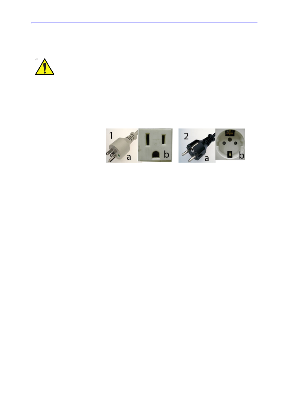
WARNING
To avoid risk of fire, the system power must be supplied from a
separate, properly rated outlet. See ‘Before the system arrives’
on page 1-8 for more information.
Under no circumstances should the AC power plug be altered,
changed, or adapted to a configuration rated less than
specified. Never use an extension cord or adapter plug.
To help assure grounding reliability, connect to a “hospital
grade” or “hospital only” grounded power outlet.
Figure 1-1. Example Plug and Outlet Configurations
1. 100-120 VAC, 10A
Plug and Outlet Configuration
2. 220-240 VAC, 10A
Overview
Plug and Outlet Configuration
NOTE: Country-specific power cords are currently available for
Argentina, Australia/New Zealand, China, Denmark, India/South
Africa, Switzerland, United Kingdom, Europe, the United States,
Israel, Brazil and Japan.
LOGIQ V2/LOGIQ V1 – User Guide 1-9
Direction 5610736-100 Rev. 9
Page 22

Getting Started
CAUTION
CAUTION
CAUTION
Environmental Requirements
The system should be operated, stored, or transported within
the parameters outlined below. Either its operational
environment must be constantly maintained or the unit must be
turned off.
NOTE: You may get an overheating message with regard to fan speed.
Ensure adequate system/room ventilation.
Table 1-1: System Environmental Requirements
Operational
(with probes)
Storage
(LOGIQ V2/LOGIQ
V1)
Transport
(LOGIQ V2/LOGIQ V1)
Temperature 10° - 40 °C
50° - 104 °F
Humidity 30 - 80% non-condensing 10 - 90%
Pressure 700 - 1060hPa 700 - 1060hPa 700 - 1060hPa
-5° - 50 °C
23° - 122 °F
non-condensing
-5° - 50 °C
23° - 122 °F
10 - 90% non-condensing
Ensure that the probe face temperature does not exceed the
normal operation temperature range.
Operating Environment
Ensure that there is sufficient air flow around the ultrasound unit
when installed in a fixed location.
Do not cover the ventilation holes of the LOGIQ V2/LOGIQ V1.
The LOGIQ V2/LOGIQ V1 system and probe connector are not
waterproof. Do not expose the device to water or any kind of
liquid.
1-10 LOGIQ V2/LOGIQ V1 – User Guide
Direction 5610736-100
Rev. 9
Page 23
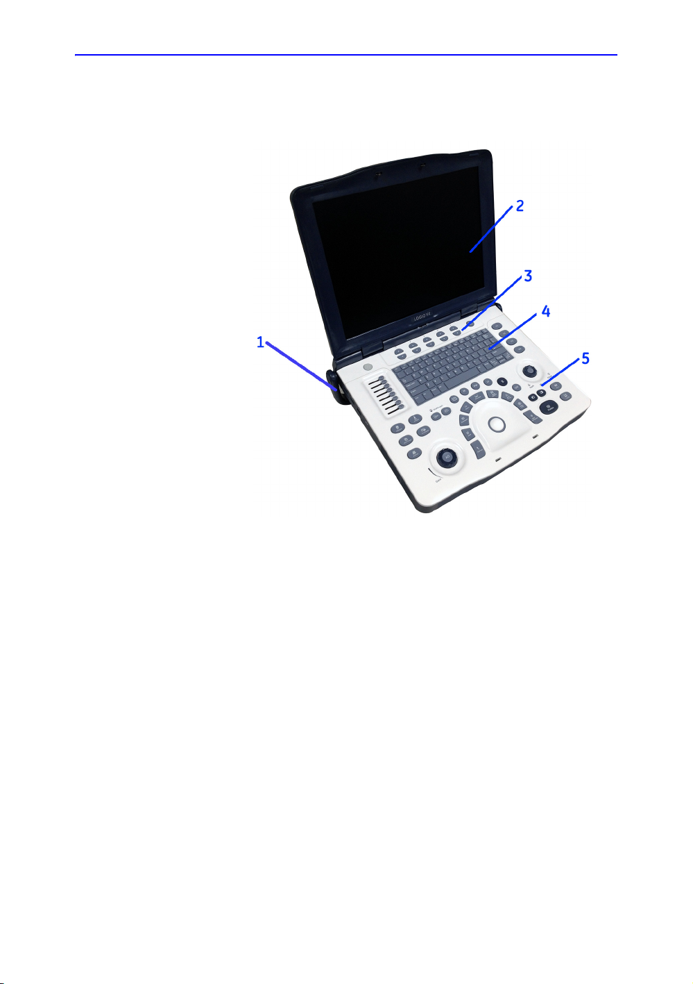
Console Graphics
Overview
The following are illustrations of the console:
Figure 1-2. LOGIQ V2/LOGIQ V1 System - an example
1. Handle
2. LCD
3. Primary Menu keys
4. Alphanumeric keys
5. Control Panel
LOGIQ V2/LOGIQ V1 – User Guide 1-11
Direction 5610736-100 Rev. 9
Page 24
Getting Started
CAUTION
WARNING
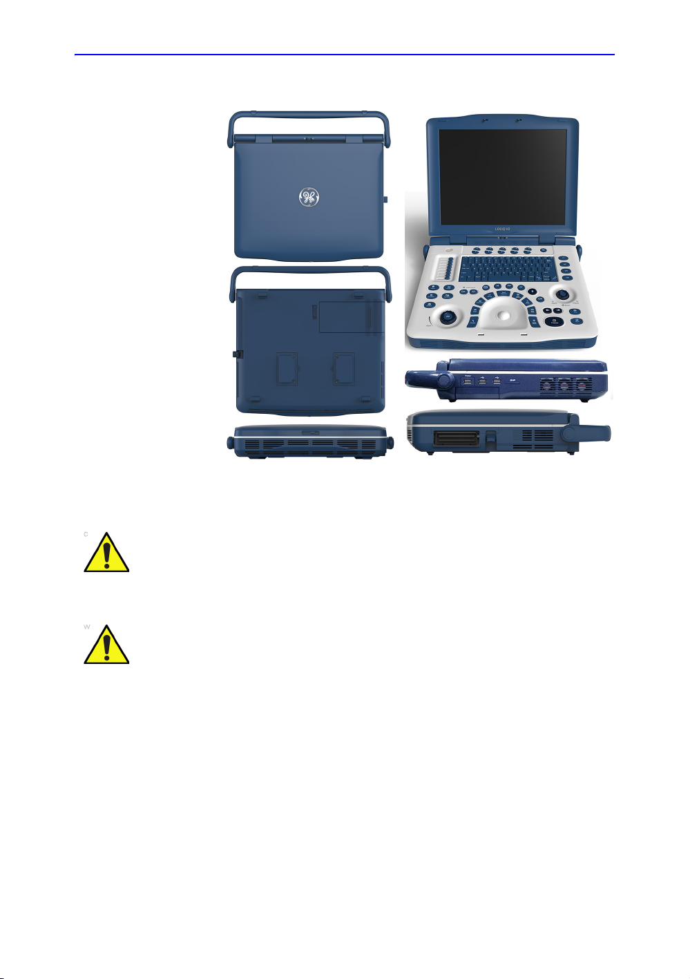
Console Graphics (continued)
Figure 1-3. LOGIQ V2/LOGIQ V1 System
Do not push objects into air vents and openings of LOGIQ V2/
LOGIQ V1. Doing so can cause fire or electric shock by
shorting out interior components.
DO NOT touch the patient and any of the connectors on the
ultrasound unit simultaneously, including ultrasound probe
connectors.
DO NOT touch the conducting parts of the USB, Ethernet,
Video, Audio cables when connecting equipment to the unit.
1-12 LOGIQ V2/LOGIQ V1 – User Guide
Direction 5610736-100
Rev. 9
Page 25

Battery
WARNING
Overview
The lithium ion battery provides power when an AC power
source is not available. A battery in the battery bay is standard
with the LOGIQ V2/LOGIQ V1. Lithium ion batteries last longer
than conventional batteries and do not require replacement as
often. You can expect about 30 minutes of battery life with a
single fully charged battery in use to supply power to the
system.
NOTE: While scanning with the battery supplying power only, the
battery life may be shorter. Always archive the data and keep
your attention on the battery status. When the battery power is
low, charge the battery immediately in case that scanning will be
interrupted and the data will be lost due to the automatic
shutdown of the system.
The lithium ion technology used in your system’s battery is
significantly less hazardous to the environment than the lithium
metal technology used in some other batteries (such as watch
batteries). Used batteries should not be placed with common
household waste products. Contact local authorities for the
location of a chemical waste collection program nearest you.
NOTE: The battery is designed to work with LOGIQ V2/LOGIQ V1
systems only. Only use the batteries authorized by GE.
Temperature Requirements
The battery should be charged, discharged and stored within the
parameters outlined below:
• Operating temperature:
• Storage temperature:
NOTE: It is recommended that the battery remaining capacity
Do not expose the battery to temperature over 60°C (140°F).
Keep it away from fire and other heat sources.
• Charge: 10 - 30°C (50 - 86°F).
• Discharge: 10 - 40°C (50 - 104°F)
should be 40% ~ 60% when the battery storage begins.
• Storage time < 3 months: -20 - 40°C (-4 - 104°F)
• Storage time >= 3 months: -20 - 20°C (-4 - 68°F)
LOGIQ V2/LOGIQ V1 – User Guide 1-13
Direction 5610736-100 Rev. 9
Page 26
Getting Started
WARNING
WARNING
CAUTION
Battery (continued)
• The battery has a safety device. Do not disassemble or
alter the battery.
• Do not short-circuit the battery by directly connecting the
negative terminals with metal objects.
• Do not heat the battery or discard it in a fire.
• Do not charge the battery near a heat source, such as a
fire or heater.
• Do not leave the battery in direct sunlight.
• Do not pierce the battery with a sharp object, hit it, or step
on it.
• Do not use a damaged battery.
• Do not solder a battery.
• Do not connect the battery to an electrical power outlet.
If the LOGIQ V2/LOGIQ V1 is not being used on a monthly
basis, the battery needs to be removed during the lengthy
non-use period.
To avoid the battery bursting, igniting, or fumes from the battery
causing equipment damage, observe the following precautions:
• Do not immerse the battery in water or allow it to get wet.
• Do not put the battery into a microwave oven or
pressurized container.
• If the battery leaks or emits an odor, remove it from all
possible flammable sources.
• If the battery emits an odor or heat, is deformed or
discolored, or in a way appears abnormal during use,
recharging or storage, immediately remove it and stop
using it. If you have any questions about the battery,
consult GE or your local representative.
1-14 LOGIQ V2/LOGIQ V1 – User Guide
Direction 5610736-100
Rev. 9
Page 27

Discharge/Charge Cycle
CAUTION
NOTE: A full discharge/charge cycle means the system is turned on
Overview
When the battery is stored for three months or more, the
customer should perform one full discharge/charge cycle.
using battery power until the battery loses its charge completely
and the system shuts down. Plug the LOGIQ V2/LOGIQ V1 in
until the battery is fully charged as indicated by a green LCD
light.
Upon receipt of the LOGIQ V2/LOGIQ V1 and before first time
usage, it is highly recommended that the customer perform one
full discharge/charge cycle.
If the battery has not been used for >2 months, the customer is
recommended to perform one full discharge/charge cycle. It is
also recommended to store the battery in a shady and cool area
with FCC (full current capacity).
One Full Discharge/Charge Cycle Process:
1. Full discharge of battery to let the LOGIQ V2/LOGIQ V1
automatically shut down.
2. Charge the LOGIQ V2/LOGIQ V1 to 100% FCC (full current
capacity).
3. Discharge of LOGIQ V2/LOGIQ V1 for complete shut down
(takes one hour for discharge).
When storing packs for more than 6 months, charge the pack at
least once during the 6 month time frame to prevent leakage
and deterioration in performance.
Use only GE recognized batteries.
LOGIQ V2/LOGIQ V1 – User Guide 1-15
Direction 5610736-100 Rev. 9
Page 28
Getting Started
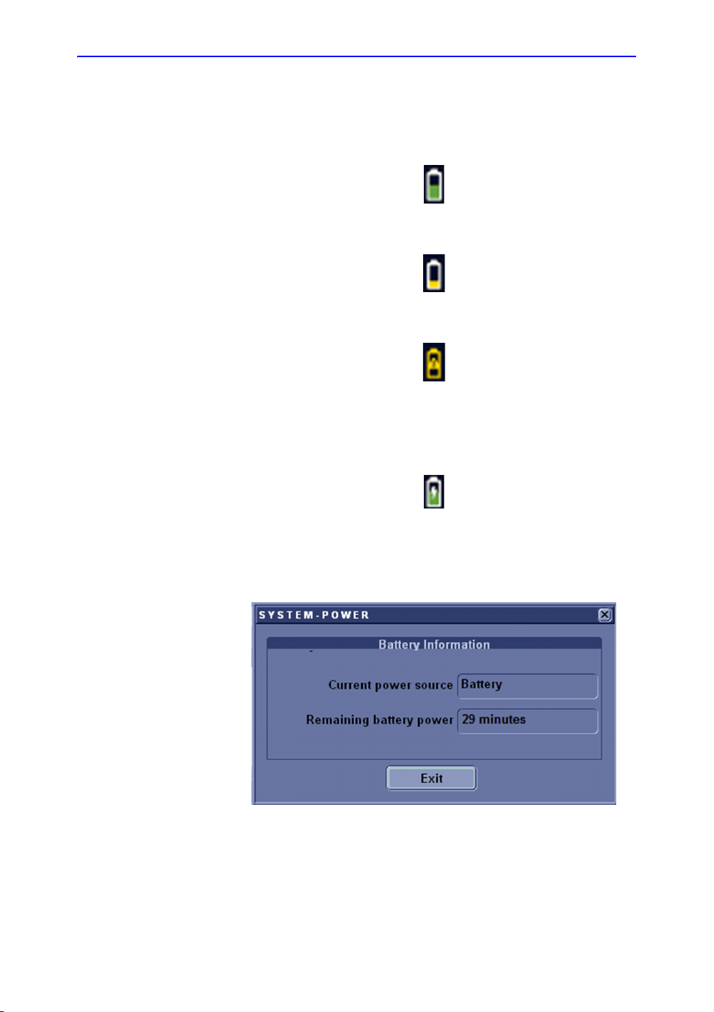
View current battery status
When the system is running on battery, there is a battery icon in
the system status bar, When there is no battery, the AC plug
Icon is displayed in the system status bar.
If the battery is in charge, the battery icon appears as being
charged in the system status bar.
Figure 1-4. Battery icon
Figure 1-5. Low Power Battery Icon
Figure 1-6. Warning Battery Icon
Figure 1-7. Charging Battery icon
Select the battery icon and the following information window
appears:
Figure 1-8. Battery Status Message
1-16 LOGIQ V2/LOGIQ V1 – User Guide
Direction 5610736-100
Rev. 9
Page 29
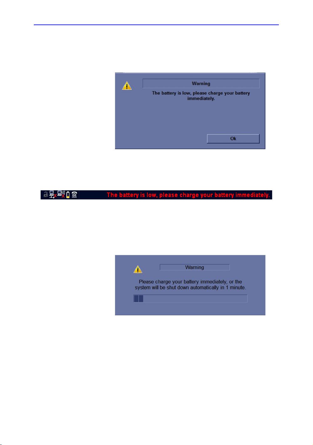
Battery power low warning
If the battery is in use and the battery power is low, the battery
icon become yellow. A warning message appears to warn the
user that the battery power is low and it needs to be charged.
The same warning message in red will continually appears in
the status bar at the bottom of the screen.
Overview
Figure 1-9. Low battery power warning
Figure 1-10. Low battery power warning on status bar
When the estimated current power remaining time is less than 3
minute, the below warning message appears on the screen to
warn the user to charge the battery immediately, or the system
will shut down automatically in 1 minute.
Figure 1-11. System shutdown warning
NOTE: When the battery power is low and the user cannot charge the
battery in time, the system automatically shuts down in 1 minute.
This protects the whole system. You need to charge the battery
immediately before the system shuts down or you may lose
useful information.
LOGIQ V2/LOGIQ V1 – User Guide 1-17
Direction 5610736-100 Rev. 9
Page 30

Getting Started
Battery error
If there is an error on the battery, the battery error icon displays.
Figure 1-12. Battery Error Icon
Follow below steps to resolve the issue:
1. Shutdown the system and disconnect AC power cable if it is
connected.
2. Remove and install the battery
3. Connect the AC power cable
4. Power on the system with AC power supply
5. Disconnect AC power cable to use the battery to supply
power to the system.
If it is still error, shutdown the system, disconnect AC power
cable if it is connected, remove the battery and contact GE
Service.
1-18 LOGIQ V2/LOGIQ V1 – User Guide
Direction 5610736-100
Rev. 9
Page 31

Battery Installation
Overview
To install the battery to the bottom cover of the system:
1. Shut down the system and disconnect the AC/DC power
cord.
2. Put the battery into the battery box through the opening
place.
Figure 1-13. Place the battery on the bottom cover
3. Push the battery completely into the box until the battery is
locked and the battery lock is in the lock position.
Figure 1-14. Lock the battery
LOGIQ V2/LOGIQ V1 – User Guide 1-19
Direction 5610736-100 Rev. 9
Page 32

Getting Started
Battery Removal
To remove the battery from the bottom cover of the system:
1. Shut down the system and disconnect the AC/DC power
cord.
2. Push up the battery lock to another end of the slot. While
hold on to the lock without release, put another hand at the
embossed position on the battery and push the battery in
the direction away from the battery box.
Figure 1-15. Unlock and push the battery
3. When the battery is released from the lock, remove it from
the battery box.
Figure 1-16. Remove the battery
1-20 LOGIQ V2/LOGIQ V1 – User Guide
Direction 5610736-100
Rev. 9
Page 33

AC Adapter
CAUTION
Overview
Do not use an AC adapter without approval by GE.
Be sure that nothing rests on the AC adapter’s power cable
and that the cable is not located where it can be tripped over or
stepped on.
Place the AC adapter in a ventilated area, such as a desk,
when you use it to run LOGIQ V2/LOGIQ V1. Do not cover the
AC adapter with paper or other items that will reduce cooling;
do not use the AC adapter inside a carrying case.
To prevent damage to the power cable of the AC adapter, DO
NOT pull excessively on the cable; DO NOT make any sharp
bends; DO NOT bend the power cable frequently.
LOGIQ V2/LOGIQ V1 – User Guide 1-21
Direction 5610736-100 Rev. 9
Page 34

Getting Started
CAUTION
CAUTION
CAUTION
WARNING
CAUTION
Peripheral/Accessory Connector Panel
LOGIQ V2/LOGIQ V1 peripherals and accessories can be
properly connected using the connector panel.
Each outer (case) ground line of peripheral/accessory
connectors are Earth Grounded.
Signal ground lines are Not Isolated.
For compatibility reasons, use only GE-approved probes,
peripherals, or accessories.
DO NOT connect any probes or accessories without approval
by GE.
The connection of equipment or transmission networks other
than as specified in these instructions can result in electric
shock hazard. Alternate connections will require verification of
compatibility and conformity to IEC/EN 60601-1 by the installer.
DO NOT touch the patient and any of the connectors on the
ultrasound unit simultaneously, including ultrasound probe
connectors.
DO NOT touch the conducting parts of the USB, Ethernet,
Video, Audio cables when connecting equipment to the unit.
When using peripheral device, observe all warnings and
cautions given in Peripheral manufacture’s manuals.
1-22 LOGIQ V2/LOGIQ V1 – User Guide
Direction 5610736-100
Rev. 9
Page 35

Peripheral/Accessory Connector Panel (continued)
Figure 1-17. Peripheral/Accessory Connector Panel
1. LCD Monitor Locker
2. Security lock
3. Port for DC In (AC Adapter)
4. Composite out port
5. S-Video out port
6. HDMI Port
7. Network Port
8. 1 Isolated USB printer port
9. 2 general USB ports — USB Flash Drive, USB HDD,
DVD-RW, Footswitch, Wireless Lan Adapter
10. 1 SD Card port
11. 1 Probe Connector Port
12. Probe Connector Locking Lever
Overview
LOGIQ V2/LOGIQ V1 – User Guide 1-23
Direction 5610736-100 Rev. 9
Page 36

Getting Started
Peripherals Connection
1. Connect the printer to the system. The printer can be
Printers Illustration
Sony UP-D897 printer
properly connected using the Isolated USB printer port.
Table 1-2: Printers Connection
Sony UP-D898MD printer
1-24 LOGIQ V2/LOGIQ V1 – User Guide
Direction 5610736-100
Rev. 9
Page 37

Printers Illustration
Sony UP-D25MD printer
HP Officejet 100 printer
Overview
Table 1-2: Printers Connection
HP Officejet Pro 8100
printer
LOGIQ V2/LOGIQ V1 – User Guide 1-25
Direction 5610736-100 Rev. 9
Page 38

Getting Started
Peripherals Connection (continued)
2. The USB connection peripherals in below table can be
properly connected using general USB ports.
Table 1-3: Peripherals Connection
Peripherals Illustration
1 Pedal Footswitch
3 Pedal Footswitch
You can configure 3-pedal
Footswitch functionality via
the Utility ->
Applications -> Footswitch
parameters.
DVD-RW
Note: Do not connect the
DVD-RW to the system
while scanning.
Note: Be sure the 2
connectors on the USB Y
cable are connected to the
system at the same time.
1-26 LOGIQ V2/LOGIQ V1 – User Guide
Direction 5610736-100
Rev. 9
Page 39

Table 1-3: Peripherals Connection
Peripherals Illustration
Wireless Card
USB Flash Drive
Overview
USB Hard Disk
LOGIQ V2/LOGIQ V1 – User Guide 1-27
Direction 5610736-100 Rev. 9
Page 40

Getting Started
Peripherals Connection (continued)
3. Other peripheral ports connection
Table 1-4: Other Peripheral ports connection
Peripherals Illustration
SD Card connection
Ethernet connection
HDMI port connection
1-28 LOGIQ V2/LOGIQ V1 – User Guide
Direction 5610736-100
Rev. 9
Page 41

Table 1-4: Other Peripheral ports connection
CAUTION
Peripherals Illustration
VGA output connection (through
an external video adapter from
HDMI)
Composite out port
You can configure the output
format via the Utility -> System ->
Peripherals.
Overview
S-Video out port
You can configure the output
format via the Utility -> System ->
Peripherals.
When using the Footswitch, DO NOT hold down the footswitch
pedal. Press and release the Footswitch pedal. Pushing and
holding down the pedal behaves the same way as pushing and
holding down a key on the keyboard.
NOTE: Please refer to the manufacture’s operation manual of each
peripheral for information needed by the user to operate the
peripheral safely.
LOGIQ V2/LOGIQ V1 – User Guide 1-29
Direction 5610736-100 Rev. 9
Page 42

Getting Started
Attaching the Security Cable
To ensure that the LOGIQ V2/LOGIQ V1 is not removed from
the premises, attach the security cable.
1. Wrap the cable around an immovable object.
Figure 1-18. Security Cable
2. Be sure to rotate the key to the unlocked position (to the
right).
3. Insert the lock into the security slot to the system’s rear side.
Figure 1-19. LOGIQ V2/LOGIQ V1 with Security Cable
4. Rotate the key to the locked position (to the left).
1-30 LOGIQ V2/LOGIQ V1 – User Guide
Direction 5610736-100
Rev. 9
Page 43

Set Up Wired Footswitch
CAUTION
Use only the GE recommended footswitch. The footswitch may
be used as select keys.
You can attach this Footswitch to the system by connecting it to
the USB port on the system.
You can configure its functionality via the Utility ->
Applications -> Settings -> Footswitch parameters.
For 3-pedal footswitch, you can configure its functionality from
the pull-down menu list of Left, Middle and Right.
Figure 1-20. 3-footswitch setting
Overview
For 1-pedal footswitch, you can configure its functionality from
the pull-down list of the Middle.
Figure 1-21. 1-footswitch setting
When using the Footswitch, DO NOT hold down the footswitch
pedal. Press and release the Footswitch pedal. Pushing and
holding down the pedal behaves the same way as pushing and
holding down a key on the keyboard.
LOGIQ V2/LOGIQ V1 – User Guide 1-31
Direction 5610736-100 Rev. 9
Page 44

Getting Started
CAUTION
Control Panel Map
1. Power On/Off
2. Primary Menu keys
3. Next key
4. TGC
5. A/N Keyboard
6. User Defined keys
7. Report key
8. Utility key
9. Patient key
10. Preset key
11. Worksheet key
Figure 1-22. Control Panel map
12. End Exam key
13. Archive key
14. Gain/AO key
15. Scan Coach keys
16. Mode keys
17. Cursor key
18. Clear key
19. Comment key
20. Active key
21. Measure key
22. Body Pattern key
23. M/D Cursor key
24. Scan Area key
25. Set/B Pause key
26. Trackball
27. Depth/Zoom/Ellipse key
28. Left/Right key
29. Freeze key
30. Print key
31. Store key
Do not apply too much force when adjusting the TGC slide pots
as this could damage the slide pots.
1-32 LOGIQ V2/LOGIQ V1 – User Guide
Direction 5610736-100
Rev. 9
Page 45

Keyboard
The standard alpha-numeric keyboard has some special
functions.
Esc Exit current display screen.
Help (F1 Key) Access Online Help
Arrow (F2 Key) Annotation arrow.
Eject (F3 Key) Eject media.
Spooler (F4 Key) Activates DICOM Job Spooler screen.
Overview
Create a Fast Key
(F5 Key)
Play a Fast Key (F6
Key)
Home/Set Home
(F7 Key)
Text1/Text2 (F8
Key)
Grab Last (F9 Key) Activate the last selected data for edit.
Word Delete (F10
Key)
Alt+D Collect the logs.
NOTE: Logs can be collected by pressing Alt+D, Only when peripheral
Creates a Fast Key.
Plays a Fast Key.
Move annotation cursor to home position; shift+key to set
current annotation cursor position as the new home position.
Switch between user text annotation overlays.
Erase word associated with comment cursor.
If you encounter a problem and cannot collect the logs
immediately:
Once the logs are collected, the engineering team would be able
to see the marker you added which will help engineering to
troubleshoot the problem.
storage devices are connected.
Detachable keys
Report key, Scan Coach key, CF key, PDI key and User defined
keys are detachable keys.
Report, Scan Coach, CF and PDI are option features for the
system, after the options are installed on the system, use the
key caps in the option kits to replace the blank key caps.
LOGIQ V2/LOGIQ V1 – User Guide 1-33
Direction 5610736-100 Rev. 9
Page 46

Getting Started
User defined keys
NOTE: The factory default settings for the User Defined Keys are TVI,
LOGIQ View, Easy 3D and Report from top to bottom. The
settings can be modified in Utility ->System -> User
Configurable Key.
After programming the user defined keys in utility page, please
adjust the key caps of user defined key on the control panel to
match with the assigned function.
Figure 1-23. User Configurable Key Preset Menu
Primary Menu keys
NOTE: Different Primary Menu are displayed depending on which
The Primary Menu keys contain exam function and mode/
function specific controls.
function is selected.
Figure 1-24. Primary Menu keys
Press up/down buttons to adjust the value of the softmenu
associated with it. Press Next to display the next group of
Primary Menu.
The Primary Menu can be configured in Utility -> Application ->
Image Controls -> Primary Menu.
1-34 LOGIQ V2/LOGIQ V1 – User Guide
Direction 5610736-100
Rev. 9
Page 47

Button description
Mode, Display and Record
This group of controls provides various functions relating to the
display mode, display orientation, image recording/saving,
freeze, gain and Cine scroll.
The Mode Controls select the desired display mode or
combinations of display modes.
• During dual display modes the L and R keys activate the
• Gain/AO is used to:
• Depth/Zoom/Ellipse controls the image depth/width and
• Print key is used to activate/print the designated recording
• Store key is used to store the images/loops to the defined
• The Freeze key is used to stop the acquisition of ultrasound
• To activate a specific mode, press the mode assigned rotary
Overview
Left or Right displayed image. See ‘Split Screen’ on
page 2-14 for more information.
• Gain: rotate to adjust gain.
• AO: press to initiate/turn off auto optimize.
activates the area/ellipse measurement function.
device.
designation.
data and freeze the image in system memory. Pressing
Freeze a second time continues live image data acquisition.
key.
LOGIQ V2/LOGIQ V1 – User Guide 1-35
Direction 5610736-100 Rev. 9
Page 48

Getting Started
Measurement and Annotation
This group of controls performs various functions related to
making measurements, annotating and adjusting the image
information.
• The Comment key enables the image text editor and
displays the annotation library.
• The Clear key is generally used to erase functions, such as
annotations/comments, body patterns and measurements.
Pressing the Clear key again exits the selected function.
• Press the Body Pattern control, it enables the Body Pattern
and displays the default pattern on the screen. When body
patterns are active, the knob rotates the probe position
indicator.
• Press Set to fix the measurement after the ellipse
adjustment is complete. The measurement is then displayed
in the measurement result window.
• The Measure key is used in all types of basic
measurements. When the Measure key is pressed, the
measurement Primary Menu is displayed.
• The Set key is used for various functions, but is generally
used to fix or finish an operation (e.g. to fix a measurement
caliper).
• The Trackball is used with almost every key function in this
group. Trackball control depends on the last key function
pressed.
1-36 LOGIQ V2/LOGIQ V1 – User Guide
Direction 5610736-100
Rev. 9
Page 49

Monitor Display
Overview
Figure 1-25. Monitor Display Tour
1. Institution/Hospital Name, Date, Time, Operator
Identification
2. Patient Name, Patient Identification
3. Power Output Readout
4. Probe Identifier. Exam Preset
5. Imaging Parameters by Mode
6. Cine Gauge
7. Image manage controls
8. Primary Menu
9. Trackball Functionality Status
10. System messages
11. Caps Lock: (lit when on), network connection
indicator (PC=connected, PC with X=not
connected), Battery Icon/Plug Icon, InSite
status, InSite controls
12. Current date and time
13. Image Preview
14. Measurement Summary Window
15. Worksheet/Direct Report
16. Probe Orientation Marker
17. Region of interest.
18. Gray/Color Bar
19. Measurement Calipers
20. Measurement Results Window
21. Image Clipboard
22. Image
23. TGC
24. Depth Scale
25. Focal Zone Indicator
26. Body Pattern
LOGIQ V2/LOGIQ V1 – User Guide 1-37
Direction 5610736-100 Rev. 9
Page 50

Getting Started
Using the Monitor Display Controls to Manage Images
You can manage images from the display via these on-display
controls.
Figure 1-26. Menu Icons
Active Images
Delete
1. Active Images Screen
2. Delete Image
3. Next/Previous Image(s).
4. Save As Menu
5. Number of Images in Exam
Press Active Images to go to the Patient Active Images page.
You can use this to delete an image from the clipboard.
To delete an image from the clipboard
1. Select the Cursor key to obtain a cursor arrow.
2. Place the cursor on the clipboard image you want to delete,
then press Set to select the image.
3. Place the cursor on the Delete icon and press Set.
A warning message is displayed asking the user to confirm
the action to perform.
4. Select Yes.
1-38 LOGIQ V2/LOGIQ V1 – User Guide
Direction 5610736-100
Rev. 9
Page 51

Next Clipboard Image
Clipboard Slide Show
Overview
Press the left arrow to move to the previous image; press the
right arrow to move to the next image.
The Clipboard Slide Show plays all images on the clipboard and
wraps around the ends. To activate, press and hold [Ctrl] +
[Previous Arrow] or [Ctrl] + [Next Arrow].
• Each image recalls for three seconds, or the length of the
loop, whichever is longer.
• You can manually skip to a new image during the slide show
by recalling it, as usual.
• To end the slide show manually, press [Ctrl] + [Previous]/
[Next] again.
• Slide Show ends when you go to live scanning, or if the
clipboard is not shown when it’s time for the next image to
load.
Save As menu
Activate Save As feature.
Number of Images in Exam
The number of images in an exam is tracked on the bottom of
these Monitor Display Controls.
LOGIQ V2/LOGIQ V1 – User Guide 1-39
Direction 5610736-100 Rev. 9
Page 52

Getting Started
CAUTION
Locking/unlocking the LCD monitor
The LCD monitor will be locked automatically when the system
is closed with a little force.
Push and slide the LCD latch slider to the right and hold on to
unlock the LCD, LCD monitor can be opened.
LCD Monitor
Adjusting the LCD monitor
The LCD monitor position can be adjusted for easy viewing.
• Tilt the LCD monitor for the optimum viewing angle. The
maximum angle is 170.
To avoid damage, DO NOT push the LCD monitor over the
maximum opening angle.
DO NOT scratch or press on the panel with any sharp
objects, such as a pencil or pen, as this may result in
damage to the panel.
NOTE: Bright light could impact readability of screen.
Figure 1-27. Unlock the LCD Monitor
1-40 LOGIQ V2/LOGIQ V1 – User Guide
Direction 5610736-100
Rev. 9
Page 53

Brightness
LCD Monitor
Adjusting the monitor's brightness is one of the most important
factors for proper image quality. If these controls are set
incorrectly, the Gain, TGC, Dynamic Range and even Power
Output may have to be changed more often than necessary to
compensate.
The proper setup displays a complete gray scale. The lowest
level of black should just disappear into the background and the
highest white should be bright, but not saturated.
To adjust the brightness:
On the alphanumeric keyboard, adjust brightness with the Fn +
Left/Right keys
Figure 1-28. Brightness
1. Brightness
NOTE: After readjusting the LCD monitor's Brightness, readjust all
preset and peripheral settings.
NOTE: The brightness of the LCD monitor should be set first as it
affects the Gain and Dynamic Range settings of your image.
Once set, this should not be changed unless the brightness of
your scanning environment changes.
LOGIQ V2/LOGIQ V1 – User Guide 1-41
Direction 5610736-100 Rev. 9
Page 54

Getting Started
Volu me
To adjust the volume:
On the alphanumeric keyboard, adjust volume with the Fn + Up/
Down keys
Figure 1-29. Volume
1. Volume
1-42 LOGIQ V2/LOGIQ V1 – User Guide
Direction 5610736-100
Rev. 9
Page 55

Before moving the system
CAUTION
CAUTION
When moving or transporting the system, follow the precautions
below to ensure the maximum safety for personnel, the system,
and other equipment.
DO NOT attempt to move the console using any cables or
fixtures, such as the probe connectors.
Handle carefully. A drop of more than 5 cm can cause
mechanical damages.
Moving the System
Moving the System
1. Shut down the system. See ‘Power Off’ on page 1-51 for
more information.
2. Unplug the power cord (if the system is plugged in).
3. Disconnect all cables from off-board peripheral devices
(external printer, etc.) and the ethernet connection from the
console.
NOTE: To prevent damage to the Power Cord, DO NOT pull
excessively on the cord or make sharp bends while
wrapping.
4. Store all probes in their original cases or in soft cloth or foam
to prevent damage.
5. Store sufficient gel and other essential accessories in the
special storage case.
LOGIQ V2/LOGIQ V1 – User Guide 1-43
Direction 5610736-100 Rev. 9
Page 56

Getting Started
CAUTION
When moving the system
• Always use the handle to move the system.
The system weighs approximately 6 kg (13.23 lbs). To avoid
possible injury and equipment damage:
• Do not let the system strike walls or door frame.
Transporting the System
Use extra care when transporting the system using vehicles. In
addition to the instructions used when moving the system (see
‘Before moving the system’ on page 1-43 for more information),
also perform the following:
1. Before transporting, place the system in its special storage
case.
2. Ensure that the system is firmly secured while inside the
vehicle.
1-44 LOGIQ V2/LOGIQ V1 – User Guide
Direction 5610736-100
Rev. 9
Page 57

Connecting the System
CAUTION
WARNING
WARNING
WARNING
Use caution to ensure that the power cable does not
disconnect during system use.
If the system is accidentally unplugged, data may be lost.
Failure to provide an adequate earth circuit can cause electrical
shock, resulting in serious injury.
Connection of additional protective earth conductors or
potential equalization conductors is not necessary in most
cases and is only recommended for situations involving
multiple equipment in a high-risk patient environment to
provide assurance that all equipment is at the same potential
and operates within acceptable leakage current limits. An
example of a high-risk patient would be a special procedure
where the patient has an accessible conductive path to the
heart such as exposed cardiac pacing leads.
System Start-Up
System Start-Up
To avoid risk of electric shock, this equipment must only be
connected to a supply mains with protective earth.
POWER OUTAGE MAY OCCUR. The ultrasound unit requires
a dedicated single branch circuit. To avoid circuit overload and
possible loss of critical care equipment, make sure you DO
NOT have other equipment operating on the same circuit.
Voltage level check
Check the rating label on the bottom of the system. Check the
voltage range indicated on the label.
LOGIQ V2/LOGIQ V1 – User Guide 1-45
Direction 5610736-100 Rev. 9
Page 58

Getting Started
Connecting the System (continued)
Figure 1-30. Example Plug and Outlet Configurations
1. 100-120 VAC, 10A
Plug (a) and Outlet (b) Configuration example
2. 220-240 VAC, 10A
Plug (a) and Outlet (b) Configuration example
NOTE: Country-specific power cords are currently available for
Argentina, Australia/New Zealand, China, Denmark, India/South
Africa, Switzerland, United Kingdom, Europe, the United States,
Israel, Brazil and Japan.
Acclimation Time
Table 1-5: System Acclimation Time Chart
Degree C 50 45 40 35 30 25 20 15 10 5 0 -5
Degree F 122 113 104 95 86 77 68 59 50 41 32 23
hours 4 2 0 000000246
1-46 LOGIQ V2/LOGIQ V1 – User Guide
Direction 5610736-100
Rev. 9
Page 59

Connecting to the electrical outlet
CAUTION
CAUTION
CAUTION
To connect the system to the electrical supply:
1. Ensure that the wall outlet is of the appropriate type.
2. Unwrap the power cable. Make sure to allow sufficient slack
in the cable so that the plug is not pulled out of the wall if the
system is moved slightly.
Use the appropriate power cord provided by or designated
by GE.
3. Attach the power plug to the system.
4. Connect the power cable to the adapter, if it is not
connected.
5. Push the power plug securely into the wall outlet.
NOTE: Do not use an extension cord or adapter plug.
Disconnect the plug from the wall outlet in case an emergency
should occur. Ensure easy access to the power outlet.
System Start-Up
To avoid leakage current above safety limits as prescribed by
IEC 60601-1 and to ensure continuity of protective earth. Only
connect LOGIQ V2/LOGIQ V1 and mains-operated
accessories to the appropriate wall outlet. DO NOT connect
them to a single or multiple socket outlets, an extension cord,
power strip or an adapter plug.
Figure 1-31. Connect the system to the electrical supply
LOGIQ V2/LOGIQ V1 – User Guide 1-47
Direction 5610736-100 Rev. 9
Page 60

Getting Started
To turn on the system
1. Check the rating label on the bottom of the system. Check
the voltage range indicated on the label.
2. Momentarily press the On/Off switch to turn the power on.
3. The system should now go through its boot-up process with
no further user intervention.
Figure 1-32. Power On/Off Switch Location
1-48 LOGIQ V2/LOGIQ V1 – User Guide
Direction 5610736-100
Rev. 9
Page 61

Power Up Sequence
NOTE: If no probe is connected, the system goes into freeze mode.
System Start-Up
The system is initialized. During this time:
• The system boots up and the status is reflected on the
monitor.
• Probes are initialized for immediate operation.
• Peripheral devices are activated on power up.
After initialization is complete, the default B-Mode screen is
displayed on the monitor (if a probe is connected).
LOGIQ V2/LOGIQ V1 – User Guide 1-49
Direction 5610736-100 Rev. 9
Page 62

Getting Started
LED
Keyboard Backlight
Press the On/Off switch to turn the power on.
After a successful boot-up process, the Power On/Off switch
illumination turns to green.
Figure 1-33. LED Indicators
1. Indicates hard disk working status. When the LED is
flashing, the system is writing or reading from the hard disk.
Color: Green
2. Indicates battery status. When the battery is charged, the
LED is green. When battery power is low, the LED is
orange.
Color: Green and Orange
Login
Logoff
The keyboard backlight is lit for operation in dimly lit room.
Personal IDs and associated passwords can be preset in Utility
-> Admin -> Users on the LOGIQ V2/LOGIQ V1.
If the User Auto Logon preset in Utility -> Admin -> Logon is
blank, you are prompted to login.
To logoff, press the Power On/Off switch momentarily and a
SYSTEM-EXIT window appears.
1-50 LOGIQ V2/LOGIQ V1 – User Guide
Direction 5610736-100
Rev. 9
Page 63

Power Off
System Start-Up
For optimum system operation, we recommend that you restart
the system at least once every 24-hour period. If you shut down
the system at the end of the day, no other action is needed.
To power off the system:
1. When you shutdown the system, enter the scan screen and
lightly press the Power On/Off switch at the front of the
system once. The System-Exit window is displayed.
NOTE: DO NOT press and hold down the Power On/Off switch to
shutdown the system. Instead, lightly press the Power On/
Off switch and select Shutdown.
2. Using the Trackball, select Shutdown.
The shutdown process takes a few seconds and is
completed when the Power On/Off switch illumination turns
from green to off.
NOTE: DO NOT select Exit for Shutdown. Exit is only available to
Service representative.
NOTE: If the system has not fully shut down in 60 seconds in the
power-off sequence, press and hold down the On/Off switch
until the system shuts down.
3. Disconnect the probes.
Clean or disinfect all probes as necessary. Store them in
their shipping cases or another appropriate probe storage
system to avoid damage.
4. Disconnect AC adapter mains plug from the power outlet.
NOTE: Disconnect the AC adapter mains plug from the outlet if the
system has been fully charged. Connect the AC adapter
mains plug to the outlet if the system needs to be charged
and then disconnect it when the system has been fully
charged.
LOGIQ V2/LOGIQ V1 – User Guide 1-51
Direction 5610736-100 Rev. 9
Page 64

Getting Started
CAUTION
WARNING
Sleep Mode (For R1.1.x)
Use Sleep Mode when you do a portable exam in order to
reduce the time to start up the system. When you use Sleep
Mode, it takes ~35 seconds to start up the system.
To activate Sleep Mode,
1. Press the On/Off switch and select Sleep.
2. One minute after the monitor goes black, unplug the power
3. To exit out of Sleep Mode, press the On/Off switch.
You need to wait at least one minute after the monitor goes
black before unplugging the power cable. The system is still in
the process of going into Sleep Mode after the monitor goes
black.
Sleep mode is not intended to replace the shutdown process.
The system should be fully shutdown every day.
cord from the wall.
1-52 LOGIQ V2/LOGIQ V1 – User Guide
Direction 5610736-100
Rev. 9
Page 65

Check System Date and Time
A warning message “Please check the system date and time are
correct” appears on the screen when the system is powered up.
This warning message appears for the possible reasons:
• The system is not boot up for more than 14 days.
• The system time has been changed by 24 hours earlier than
the current system time of last boot-up.
This warning message is to remind the user to check the system
date in case the system date and time is incorrect.
System Start-Up
Figure 1-34. Check system date and time message
Move the cursor to OK and press Cursor key on the control
panel to select OK. The system enters scanning mode.
Check the system date and time. If it is incorrect, follow below
steps to reset the system date and time.
1. Enter Utility -> System -> General -> Date/Time.
2. Reset the system date and time.
3. Select Apply and then select OK.
4. Select Save.
LOGIQ V2/LOGIQ V1 – User Guide 1-53
Direction 5610736-100 Rev. 9
Page 66

Getting Started
CAUTION
CAUTION
CAUTION
CAUTION
Introduction
Only use approved probes.
Connecting the Probe
Inspect the probe before and after each use for damage or
degradation to the housing, strain relief, lens, seal, cable and
connector. DO NOT use a transducer which appears damaged
until functional and safe performance is verified. A thorough
inspection should be conducted during the cleaning process.
Probes
Remove any dust or foam rests from the probe pins.
Fault conditions can result in electric shock hazard. Do not
touch the surface of probe connectors which are exposed
when the probe is removed. Do not touch the patient when
connecting or disconnecting a probe.
Probes can be connected at any time, regardless of whether the
console is powered on or off.
To connect a probe:
1. Place the probe's carrying case on a stable surface and
open the case.
2. Carefully remove the probe and unwrap the probe cord.
DO NOT allow the probe head to hang free. Impact to the
probe head could result in irreparable damage.
1-54 LOGIQ V2/LOGIQ V1 – User Guide
Direction 5610736-100
Rev. 9
Page 67

Connecting the Probe (continued)
CAUTION
3. Align the connector with the probe port and carefully push
into place with the cable facing the front of the system.
Figure 1-35. Probe connection to LOGIQ V2/LOGIQ V1
4. Flip the connector locking lever up.
Probes
Figure 1-36. Probe connector locking lever
5. Carefully position the probe cord so it is free to move and is
not resting on the floor.
6. When the probe is connected, it is automatically activated.
Make sure that the probe and application names displayed on
the screen correspond to the actual probe and application
selection.
LOGIQ V2/LOGIQ V1 – User Guide 1-55
Direction 5610736-100 Rev. 9
Page 68

Getting Started
Cable Handling
Take the following precautions with probe cables:
• Do not bend the cable acutely
• Avoid crossing cables between probes.
Disconnecting the Probe
Probes can be disconnected at any time. However, the probe
should not be active when disconnecting the probe.
1. Press the connector locking lever down.
2. Pull the probe connector straight out of the probe port
carefully.
3. Ensure the cable is free.
4. Be sure that the probe head is clean before placing the
probe in its storage box or wall hanging unit.
1-56 LOGIQ V2/LOGIQ V1 – User Guide
Direction 5610736-100
Rev. 9
Page 69

2-Probe Port Adapter (option)
Mounting 2-Probe Port Adapter to LOGIQ V2/LOGIQ V1
1. Turn over LOGIQ V2/LOGIQ V1 and 2-Probe Port Adapter
to let the back upward.
Probes
Figure 1-37. 2-Probe Port Adapter connection, Step 1
2. Align the 2 location pins of 2 Probe Port Adapter with the
location holes of LOGIQ V2/LOGIQ V1 and carefully push
into place, then screw 3 screws.
Figure 1-38. 2-Probe Port Adapter connection, Step 2
LOGIQ V2/LOGIQ V1 – User Guide 1-57
Direction 5610736-100 Rev. 9
Page 70

Getting Started
Mounting 2-Probe Port Adapter to LOGIQ V2/LOGIQ V1 (continued)
3. Flip the connector locking lever down.
Figure 1-39. 2-Probe Port Adapter connection, Step 3
4. Turn over the system with 2-Probe Port Adapter, now the
2-Probe Port Adapter is connected successfully.
Figure 1-40. 2-Probe Port Adapter connection, Step 4
1-58 LOGIQ V2/LOGIQ V1 – User Guide
Direction 5610736-100
Rev. 9
Page 71

Connecting Probes to the 2-Probe Port Adapter
Follow the probe connection procedure to connect the probe to
the 2-Probe Port Adapter.
Figure 1-41. 2-probe Port Adapter connection, Step 5
Probes
Selecting the probe
Press Patient or Preset on the control panel to select the probe.
Figure 1-42. Select the probe
LOGIQ V2/LOGIQ V1 – User Guide 1-59
Direction 5610736-100 Rev. 9
Page 72

Getting Started
Archive Screen (For R1.0.x)
Beginning an Exam
Figure 1-43. Archive view Screen 1
1. Image Management: Select to manage the images.
2. EZBackup/EZMove: One-step method to backup / move
patient images to an external media.
3. Review: Select to review the image.
4. Thumbnail image: Provide a thumbnail image of current
selected image.
5. Scan: Select to start scanning.
1-60 LOGIQ V2/LOGIQ V1 – User Guide
Direction 5610736-100
Rev. 9
Page 73

Archive Screen (For R1.0.x) (continued)
Beginning an Exam
Figure 1-44. Archive view Screen 2
6. Patient View/Exam View: Lists the patients in the database /
Displays the Exam History of the selected patient.
7. Dataflow Selection: Select the appropriate patient dataflow.
8. Delete: Select to delete the selected patient.
9. Delete All: Select to delete all the patient.
10. Folder Information: Displays the Exam History of the
selected patient.
NOTE: Columns drive the ordering of the patients displayed. The
colums that you select drives
paient database.
the order of the the displayed
LOGIQ V2/LOGIQ V1 – User Guide 1-61
Direction 5610736-100 Rev. 9
Page 74

Getting Started
CAUTION
WARNING
WARNING
CAUTION
WARNING
Archive Screen (For R1.0.x) (continued)
To maintain optimum performance and to safeguard patient
data, keep the total number of patients in the database below
1,000.
To reduce the total number of patients in the database, perform
EZbackup and Backup (Patient Archive and Report Archive),
then delete the patient from the system.
Archive Screen (For R1.1.x)
Press Archive on the control panel to enter archive screen.
See ‘Patient Screen (For R1.1.x)’ on page 1-65 for more
information.
Scanning a New Patient
Imaging functions may be lost without warning. Develop
emergency procedures to prepare for such an occurrence.
Ensure you have selected a dataflow. If No Archive is selected,
no patient data is saved. The Dataflow will display as below:
To avoid patient identification errors, always verify the
identification with the patient. Make sure the correct patient
identification appears on all screens and hard copy prints.
Always use the minimum power required to obtain acceptable
images in accordance with applicable guidelines and policies.
1-62 LOGIQ V2/LOGIQ V1 – User Guide
Direction 5610736-100
Rev. 9
Page 75

Scanning a New Patient (continued)
WARNING
WARNING
Always use the system on a flat surface in the patient
environment.
Ensure that the hands of the patient are away from the system
during the exam.
The position of the operator and the patient vary by scan
region.
In most cases, the operator sits/stands straight in front of the
operator console and the patient lies on the bed on the right (or
left) side of the system.
Beginning an Exam
LOGIQ V2/LOGIQ V1 – User Guide 1-63
Direction 5610736-100 Rev. 9
Page 76

Getting Started
Patient Screen (For R1.0.x)
When starting a new patient’s exam, ensure you do the
following:
1. Select Patient on the control panel.
Figure 1-45. Create a new patient
2. Patient ID will be generated automatically by the system.
The operator is able to edit the Patient ID and fill in other
patient information.
3. Select the probe and application.
4. Select Scan to start scanning.
5. Perform the exam.
If the patient information needs to change while scanning,
select Patient again. If the probe or preset needs to change
while scanning, select Preset again.
6. Press Store key to store the static image or cineloop saved
in the exam to the clipboard.
7. When the scanning is complete, select End Exam on the
control panel to end current patient. The system
permanently stores all images of the current patient.
The system creates the new patient and the new folder to
store all images in the archive screen.
1-64 LOGIQ V2/LOGIQ V1 – User Guide
Direction 5610736-100
Rev. 9
Page 77

Patient Screen (For R1.1.x)
Beginning an Exam
Figure 1-46. Patient Screen
1. Image Management
2. Function Selection
3. EZBackup/EZMove
4. Dataflow Selection
5. Scan
6. Patient Information
7. Category Selection
8. Exam Information
9. Patient View/Exam View
LOGIQ V2/LOGIQ V1 – User Guide 1-65
Direction 5610736-100 Rev. 9
Page 78

Getting Started
Patient Screen (For R1.1.x) (continued)
When starting a new patient’s exam, ensure you do the
following:
1. Select Patient on the control panel.
2. Select New Patient on the patient menu.
If there are images on the clipboard, a pop-up menu
appears. Specify whether you want to store images, delete
images, or go to active images.
3. Choose the exam category.
4. Verify the dataflow.
NOTE: DO NOT use the removable media Dataflows on the New
patient menu.
NOTE: The system will display a warning dialog when the patient is
registered to “No Archive”. if the “Warn register to No
Archive” preset is selected in the Utility -> Connectivity ->
Miscellaneous menu, a warning displays. Please select a
different dataflow for permanent storage of patient data.
5. Fill in patient information.
NOTE: You can also select a patient from the patient database at
the bottom of the Patient menu if the patient has a patient
ID.
NOTE: Columns drive the ordering of the patients displayed. The
colums that you select drives
paient database.
NOTE: Do not use the following characters when filling in patient
information:
“ ‘ \ / : ; . , * < > | + = [ ] &
6. Select Register. Enter Past OB Exam information, if
desired.
7. Select the probe to start scanning (or select Esc, Scan, or
Freeze).
8. Perform the exam.
the order of the the displayed
1-66 LOGIQ V2/LOGIQ V1 – User Guide
Direction 5610736-100
Rev. 9
Page 79

Patient Screen (For R1.1.x) (continued)
CAUTION
9. Store the images/loops to the clipboard.
To store the still image, press Freeze and run the cineloop
using the Trackball. Select the frame and press Store.
To store the cineloop, press Freeze and run the cineloop
using the Trackball. Select the start/end frame and run the
selected loop. Press Store.
10. When you have completed the study, press End Exam. The
Active Images screen displays. Select the images (still
frame or cineloop) you want to store or simply select
Permanent Store to store the images permanently.
After completing the measurement, verify that the
measurement result window is updated before you send or
save the image.
Beginning an Exam
LOGIQ V2/LOGIQ V1 – User Guide 1-67
Direction 5610736-100 Rev. 9
Page 80

Getting Started
Entering a Patient List (For R1.1.x)
All patient information can be entered before starting an exam.
1. Press Patient to display the Patient Screen.
2. Press New Patient to erase the current patient data.
3. Select Store All if data from previous patient was not saved.
4. Enter the Patient ID.
5. Enter the patient and exam information.
6. Press Register.
7. Repeat above steps as required.
Select the patient from the Patient List. Select Resume Exam to
continue the last exam that was performed on the selected
patient.
Select New Exam to start a new exam on the selected patient.
1-68 LOGIQ V2/LOGIQ V1 – User Guide
Direction 5610736-100
Rev. 9
Page 81

Starting a new exam on an existing patient
For R1.0.x software:
1. Select Archive on the control panel.
2. Select the patient from the Patient List.
3. Select Scan to enter into scanning, perform the exam.
If the patient information needs to change while scanning,
select Patient.
4. Select Preset on the control panel to select the probe and
application.
If the probe and preset needs to change while scanning,
select Preset again.
5. Press the Store key to store the static image or cineloop
saved in the exam to the clipboard.
6. When you have completed the study, select End Exam on
the control panel or Primary Menu to end current patient.
The system permanently stores all images of the current
patient automatically.
Select New Exam to start a new exam on the selected
patient.
A new folder is automatically created on that patient.
Beginning an Exam
Figure 1-47. Exam View
For R1.1.x software:
1. Select Patient on the control panel.
2. Select the patient from the Patient List.
3. Select New Exam.
4. A new exam is created. Enter the data and begin the scan.
LOGIQ V2/LOGIQ V1 – User Guide 1-69
Direction 5610736-100 Rev. 9
Page 82

Getting Started
Scanning without entering any patient data
For R1.0.x software:
To scan a patient without entering any patient data until the end
of the exam:
1. Select End Exam on the control panel to end the last
patient’s exam. The system permanently stores all images
of that patient automatically.
2. Scan the new patient and save images to the clipboard
without patient information. The system displays a warning
message “Warning: A patient must be selected for
permanent storage of image”. Select OK.
3. Select Patient on the control panel to create a new patient,
the following dialog displays if there is unsaved exam data.
Figure 1-48. Unsaved Exam Data
a. Store All (Auto ID). Store the unsaved data to the
patient that is auto created by the system, and then a
new patient screen displays.
b. Link to new patient. A new patient screen displays,
and link the unsaved images to the new patient.
c. Delete All. Delete all the unsaved images, and then a
new patient screen displays.
d. Cancel. Do nothing with the unsaved data, and return to
scanning.
1-70 LOGIQ V2/LOGIQ V1 – User Guide
Direction 5610736-100
Rev. 9
Page 83

Beginning an Exam
Scanning without entering any patient data (continued)
For R1.1.x software:
To scan a patient without entering any patient data until the end
of the exam:
1. Scan the patient and save images to clipboard without the
patient information, the system displays a Warning
message, “A patient must be selected for permanent
storage of images.” Select OK, a warning message is also
displayed at the bottom of the image monitor in red.
2. When the scanning is finished, press Patient to display the
Patient Search screen.
3. Enter the Patient ID, patient data and exam information as
necessary, select Register.
4. If images or measurements have been stored to the
clipboard, the system will display the following message:
“Unsaved images, measurements or fetus number will be
linked to the current patient information, continue?” Press
OK if you want to permanently store the images/
measurements that were just taken.
5. Enter the Active Images Screen, select Permanent Store.
6. Return to patient page, select New Patient.
LOGIQ V2/LOGIQ V1 – User Guide 1-71
Direction 5610736-100 Rev. 9
Page 84

Getting Started
Changing Current Patient to Existing Patient (For R1.0.x)
To change the current patient (with/without patient ID) to an
existing patient, when there are some unsaved images on the
clipboard for the current patient:
1. Scan current patient and store images/cineloops to the
clipboard
2. Press Archive on the control panel to go to Archive Screen
and select the existing patient.
Figure 1-49. Unsaved Exam Data (Archive)
3. The option is different if the current patient is with or without
patient ID.
a. With Patient ID: Store All (xxx). Store the unsaved data
under the patient ID. The patient ID should be the
current patient ID.
Then Select Scan to begin scanning, a dialog displays:
”Current Patient will be changed to ID: xxx. Do you want
to continue?” Select Yes to change to the selected
patient, select No to keep the current patient.
b. Without Patient ID: Store All (Auto ID). Store the
unsaved data to the patient that is auto created by the
system.
1-72 LOGIQ V2/LOGIQ V1 – User Guide
Direction 5610736-100
Rev. 9
Page 85

Beginning an Exam
Changing Current Patient to Existing Patient (For R1.0.x)
(continued)
4. Review Images. Review the unsaved images in Active
Image page.
Then Select Scan to begin scanning on the current patient.
5. Delete All. Delete all the unsaved images.
Then Select Scan to begin scanning, a dialog displays: ”Do
you really want to delete all temporary images?” Select Ok
to delete all temporary images, select Cancel to do nothing
with the unsaved data, and return to Archive page.
6. Cancel. Do nothing with the unsaved data, and return to
Archive page.
LOGIQ V2/LOGIQ V1 – User Guide 1-73
Direction 5610736-100 Rev. 9
Page 86

Getting Started
Changing Current Patient to Existing Patient (with Patient ID) (For
R1.1.x)
To change the current patient (with patient ID) to an existing
patient, when there are some unsaved images on the clipboard
for the current patient:
Select the existing patient from the patient list, the following
dialog displays.
Figure 1-50. Unsaved Exam Data
1. Store All All the unsaved images will be saved to the
current patient.
2. Review Images. Review the unsaved images in Active
Images page and select to permanent store or delete.
3. Delete All. Delete all the unsaved images.
The system will display a dialog: "
all temporary images
iamges, select Cancel not to delete the images.
4. Cancel. Do nothing with the unsaved data, and return to
Patient page.
?" Select OK to delete the unsave
Do you really want to delete
1-74 LOGIQ V2/LOGIQ V1 – User Guide
Direction 5610736-100
Rev. 9
Page 87

Beginning an Exam
Changing Current Patient to Existing Patient (without Patient ID) (For
R1.1.x)
To change the current patient (without patient ID) to an existing
patient, when there are some unsaved images on the clipboard
for the current patient:
Select the existing patient from the patient list, the following
dialog displays.
Figure 1-51. Unsaved Exam Data
1. Store All All the unsaved images will be saved. The current
patient doesn't have Patient ID, the system will indicate to
enter patient ID.
Figure 1-52. Enter Patient ID
LOGIQ V2/LOGIQ V1 – User Guide 1-75
Direction 5610736-100 Rev. 9
Page 88

Getting Started
Changing Current Patient to Existing Patient (without Patient ID) (For
R1.1.x) (continued)
• Input manually Input the Patient ID and other
information manually, and then select Register to
register the new patient. And the system will display:
"Unsaved images, measurements or fetus number will be
linked to the current patient information, continue?" Select OK
to save the images.
• Auto Generate The system will generate a new patient
ID and the unsaved images will be saved to this new
patient automatically.
2. Review Images. Review the unsaved images in Active
Images page and select to permanent store or delete.
3. Delete All. Delete all the unsaved images.
The system will display a dialog: "
all temporary images
iamges, select Cancel not to delete the images.
4. Cancel. Do nothing with the unsaved data, and return to
Patient page.
?" Select OK to delete the unsave
Do you really want to delete
1-76 LOGIQ V2/LOGIQ V1 – User Guide
Direction 5610736-100
Rev. 9
Page 89

End Exam
Beginning an Exam
For R1.0.x software:
End Exam should be selected at the end of each exam. The
system will automatically store all images of current patient
permanently.
The system creates the new patient and the new folder to store
all images in the archive screen. Each patient has only one
folder per day, regardless how many exams are performed in
that day.
For R1.1.x software:
To end a patient:
Press Patient -> New Patient, then select Store All in the
pop-up menus to store exam data.
LOGIQ V2/LOGIQ V1 – User Guide 1-77
Direction 5610736-100 Rev. 9
Page 90

Getting Started
CAUTION
Deleting the existing patient/exam/image
Before deleting a patient or image from the Patient Screen,
make sure you have already saved the data with EZBackup/
EZMove, Backup, or Export. Verify the media before deletion.
Deleting the existing patient
1. Search and select the patient in the patient list.
2. Select Delete. The confirmation dialog box displays.
OR
Press the Cursor key. A pop-up menu displays. Select
Delete. The confirmation dialog box displays.
3. Select OK to delete or Cancel.
Delete multiple patients from the patient list
1. Select the multiple patients to be deleted from the patient list
by holding down the Control key and selecting patients one
by one or holding down the Shift key to select a group of
patients.
2. Select Delete. The confirmation dialog box displays.
OR
Press the Cursor key. A pop-up menu displays. Select
Delete. The confirmation dialog box displays.
3. Select OK to delete or Cancel.
Deleting the existing exam
1. Search and select the patient in the patient list under patient
screen.
2. Select Exam View to display patient exam screen.
3. Select the exam to be deleted.
4. Select Delete. The confirmation dialog box displays.
5. Select OK to delete or Cancel.
1-78 LOGIQ V2/LOGIQ V1 – User Guide
Direction 5610736-100
Rev. 9
Page 91

Deleting the existing image
1. Search and select the patient in the patient list under patient
screen.
2. Select Exam View. The patient exam screen displays.
3. Select the exam which contains the image to be deleted.
4. Select Active Images to display the image list.
5. Select the image to delete and select Delete. The
confirmation dialog box displays.
6. Select Delete to delete or Cancel to cancel.
Beginning an Exam
LOGIQ V2/LOGIQ V1 – User Guide 1-79
Direction 5610736-100 Rev. 9
Page 92

Getting Started
1-80 LOGIQ V2/LOGIQ V1 – User Guide
Direction 5610736-100
Rev. 9
Page 93

Chapter 2
Performing an Exam
Optimizing the Image, Measurement and Analysis
LOGIQ V2/LOGIQ V1 – User Guide 2-1
Direction 5610736-100 Rev. 9
Page 94

Performing an Exam
Optimizing the Image
B-Mode Controls
B-Mode is intended to provide two-dimensional images and
measurement capabilities concerning the anatomical structure
of soft tissue.
Table 2-1: B-Mode Controls
Control Bioeffect Description/Benefit
Depth Yes Depth controls the distance over which the B-Mode images
anatomy, and the field of view. To visualize deeper structures,
increase the depth. To visualize the flatter structures, decrease the
depth.
Gain No B-Mode Gain increases or decreases the amount of echo
Focus Yes Increases the number of focal zones, moves the focal zone(s) and
Auto Optimize No Auto Optimize (Auto) lets you optimize the image based upon the
Mode Cursor No Displays the M/D-Mode cursor on the B-Mode image.
CrossXBeam Yes CrossXBeam is the process of combining three or more frames
Coded Harmonic
Imaging (CHI)
Yes Harmonic imaging utilizes Digitally Encoded Ultrasound (DEU).
information displayed in an image. It may have the effect of
brightening or darkening the image if sufficient echo information is
generated.
change the zone width so that you can tighten up the beam for a
specific area. A graphic caret corresponding to the focal zone
position(s) appears on the right edge of the image.
actual B mode image data (Auto Tissue Optimize, ATO). The
preset levels (Low, Medium and High) allow you to pick a
preference for the contrast enhancement in the resulting image.
Low does the least amount of contrast enhancement, high does the
most.
Auto is available in single or multi image, on live, frozen or CINE
images (in B-Mode only), and while in zoom and in Spectral
Doppler.
from different steering angles into a single frame. CrossXBeam is
available on Convex and Linear probes.
CrossXBeam combines multiple co-planar images from different
view angles into a single image at real-time frame rates, using
bi-cubic interpolation.
Coded Harmonics enhances near field resolution for improved
small parts imaging as well as far field penetration.
2-2 LOGIQ V2/LOGIQ V1 – User Guide
Direction 5610736-100
Rev. 9
Page 95

Optimizing the Image
Table 2-1: B-Mode Controls (Continued)
Control Bioeffect Description/Benefit
Frequency Yes Switch the frequency.
Steer Yes You can slant the B-Mode or Color Flow acoustic beam without
moving the probe. The steer function only applies to linear probes.
Virtual Convex Yes On Linear and Sector probes, Virtual Convex provides a larger field
TGC No TGC amplifies returning signals to correct for the attenuation
Width Yes You can widen or narrow the size of the sector/convex angle to
Tilt Yes You can steer the sector angle to get more information without
Revert No Flips the image 180 degrees left/right.
Dynamic Range No Dynamic Range controls how echo intensities are converted to
Line Density Yes Optimizes B-Mode frame rate or spatial resolution for the best
Gray Map No The system supplies B, M, and Doppler Mode system maps.
Frame Average No Temporal filter that averages frames together, thereby using more
of view in the far field.
CrossXBeam is available on Virtual Convex with linear probes.
caused by tissues at increasing depths. TGC slide pots are spaced
proportionately to the depth. The area each pot amplifies varies as
well. A TGC curve may appear on the display (if preset), matching
the controls that you have set (except during zoom). You can
choose to deactivate the TGC curve on the image.
maximize the image's region of interest (ROI).
moving the probe while in B-Mode, M-Mode, Doppler Mode, and
Color Flow Mode.
NOTE: Tilt is not available on linear probe.
NOTE: Tilt is available when CrossXBeam is off.
shades of gray, thereby increasing the adjustable range of contrast.
possible image.
pixels to make up one image. This has the effect of presenting a
smoother, softer image.
Colorize No Colorize is the colorization of a conventional B-Mode image or
Doppler Spectrum to enhance the user's ability to discern B, M, and
Doppler Mode intensity valuations. Colorize is NOT a Doppler
Mode.
NOTE: You can colorize real-time or CINE images or Timeline
CINE.
Colorizes the gray scale image to enhance the eye's discrimination
capability. Spectrum Colorize colorizes the spectrum as a function
of power using the inverse of the Colorize map for the signal
intensity in each Doppler line. Colorize enhances the visibility of the
spectrum's characteristics and enhances your ability to identify
spectral broadening and the edge contours of the spectrum used to
define the peak frequency/velocity.
The colorize bar displays while Colorize is activated.
LOGIQ V2/LOGIQ V1 – User Guide 2-3
Direction 5610736-100 Rev. 9
Page 96

Performing an Exam
Table 2-1: B-Mode Controls (Continued)
Control Bioeffect Description/Benefit
Edge Enhance No Edge Enhance brings out subtle tissue differences and boundaries
by enhancing the gray scale differences corresponding to the
edges of structures.
Rotation No You can flip the image up/down.
CAUTION: When reading an rotated image, be careful to observe
the probe orientation to avoid possible confusion over scan
direction or left/right image reversal.
Rejection No Selects a level below which echoes will not be amplified (an echo
must have a certain minimum amplitude before it will be
processed).
Suppression No Suppresses the noise in the image.
SRI-HD (Option) No SRI-HD (Speckle Reduction Imaging High Definition) is an adaptive
LOGIQ View
(Option)
No LOGIQ View provides the ability to construct and view a static 2D
algorithm to reduce the speckle in the ultrasound image.
image which is wider than the field of view of a given transducer.
This feature allows viewing and measurements of anatomy that is
larger than what would fit in a single image. Examples include
scanning of vascular structures and connective tissues in the arms
and legs.
LOGIQ View constructs the extended image from individual image
frames as the operator slides the transducer along the surface of
the skin in the direction of the scan plane. The quality of the
resulting image is somewhat user-dependent and requires some
additional skill and practice to develop proper technique and
become fully proficient.
LOGIQ View is only available in B mode.
2-4 LOGIQ V2/LOGIQ V1 – User Guide
Direction 5610736-100
Rev. 9
Page 97

Color Flow Mode Controls
Color Flow Mode and Color M-Mode are Doppler Modes
intended to add color-coded qualitative information concerning
the relative velocity and direction of fluid motion within the
B-Mode or M-Mode image.
NOTE: Color Flow Mode is an option for LOGIQ V1.
Table 2-2: Color Flow Mode Controls
Control Bioeffect Description/Benefit
Optimizing the Image
Flow Selection Yes In the Lower Extremity Vein (LEV) and Abdominal applications, you
Gain No Gain amplifies the overall strength of echoes processed in the
Scale (Velocity
Scale)
Wall Filter No Filters out low flow velocity signals. It helps get rid of motion
Size/Position Yes Adjust size and position of the color window.
Invert (Color Invert) No Lets you view blood flow from a different perspective, e.g., red
Baseline No Changes the Color Flow or Doppler spectrum baseline to
Angle Steer Yes You can slant the ROI of the Color Flow linear image left or right to
Yes Increases/decreases the Scale on the color bar.
can quickly select the flow state via a shortcut on the Color Flow
Mode menu.
Color Flow window or spectral Doppler timeline.
artifacts caused from breathing and other patient motion.
away (negative velocities) and blue toward (positive velocities).
You can invert a real-time or frozen image.
NOTE: Invert reverses the color map, NOT the color PRF.
accommodate higher velocity blood flow. Minimizes aliasing by
displaying a greater range of forward flow with respect to reverse
flow, or vice versa.
Baseline adjusts the alias point. The default baseline is at the
midpoint of the color display and at the midpoint of the color bar
reference display.
get more information without moving the probe. The Angle Steer
function only applies to linear probes.
Accumulation No Accumulation enhances the flow in an image.
Color Flow Line
Density
Map No Allows you to select a specific color map. After you have made your
Map Compress No Change the gradation of color map.
Threshold No Limits color flow overlay to low level echoes inside vessel walls.
Frame Average No Averages color frames.
Yes Optimizes the Color Flow frame rate or spatial resolution for the
best possible color image.
selection, the color bar displays the resultant map.
Helps minimize color `bleeding' outside vessel walls.
LOGIQ V2/LOGIQ V1 – User Guide 2-5
Direction 5610736-100 Rev. 9
Page 98

Performing an Exam
Table 2-2: Color Flow Mode Controls (Continued)
Control Bioeffect Description/Benefit
Transparency Map No Brings out the tissue behind the color map.
Spatial Filter No Smooths out the color, makes it look less pixely.
Flash Suppression No Activates/deactivates Flash Suppression, a motion artifact
elimination process.
Packet Size Yes Controls the number of samples gathered for a single color flow
Sample Volume Yes Adjusts the size of the color flow doppler transmit wave (or pulse)
CF/PDI Auto Sample
Vol ume
CF/PDI Focus Depth Yes
CF/PDI Frequency Yes
CF/PDI Auto
Frequency
CF/PDI Center
Depth
PDI Yes Power Doppler Imaging (PDI) is a color flow mapping technique
TVI (Option) Yes Tissue Velocity Imaging (TVI) calculates and color-codes the
Yes Set the default value at Utility -> Imaging -> CF Mode.
Ye s
Ye s
vector.
and size (or length). Lower setting gives better flow resolution and
a higher setting increases sensitivity.
used to map the strength of the Doppler signal coming from the
tissue rather than the frequency shift of the signal. Using this
technique, the ultrasound system plots color flow based on the
number of reflectors that are moving, regardless of their velocity.
PDI does not map velocity, therefore it is not subject to aliasing.
velocities in tissue. The tissue velocity information is acquired by
sampling of tissue Doppler velocity values at discrete points.The
information is stored in a combined format with gray scale imaging
during one or several cardiac cycles with high temporal resolution.
TVD (Option) Yes TVD: Tissue Velocity Doppler: based on TVI mode, activate a
sample volume of the PW ventricular wall to get the spectral
information of the sample section.
Q Analysis (Option) No Q Analysis is available for the image loop acquired in the following
modes: TVI, CF and PDI. All of the Q Analysis modes operate
similarly, with some variation.
2-6 LOGIQ V2/LOGIQ V1 – User Guide
Direction 5610736-100
Rev. 9
Page 99

M-Mode Controls
M-Mode is intended to provide a display format and
measurement capability that represents tissue displacement
(motion) occurring over time along a single vector.
Table 2-3: M-Mode Controls
Control Bioeffect Description/Benefit
Optimizing the Image
Sweep Speed Yes Changes the speed at which the timeline is swept.
Anatomical M-Mode
(option)
Yes Anatomical M-Mode gives you the ability to manipulate the cursor
Available in M-Mode, Doppler Mode and M Color Flow Mode.
at different angles and positions. The M-Mode display changes
according to a motion of the M cursor.
M Color Flow Mode
M Color Flow is used for cardiac applications. Color Flow
overlays color on the M-Mode image using velocity and variance
color maps. The Color Flow wedge overlays the B-Mode image
and M-Mode time line.
See ‘Color Flow Mode Controls’ on page 2-5 for more
information.
LOGIQ V2/LOGIQ V1 – User Guide 2-7
Direction 5610736-100 Rev. 9
Page 100

Performing an Exam
Doppler Mode Controls
Doppler is intended to provide measurement data concerning
the velocity of moving tissues and fluids. PW Doppler lets you
examine blood flow data selectively from a small region called
the sample volume.
Table 2-4: Doppler Mode Controls
Control Bioeffect Description/Benefit
Auto Spectral
Optimize [ASO]
(Auto)
Set/ B Pause Yes Toggles between B/CF mode and PWD mode when simultaneous
Doppler sample
volume gate position
(Trackball)
Doppler sample
volume length
Scale (Velocity
Scale)
Angle Correct No Estimates the flow velocity in a direction at an angle to the Doppler
Quick Angle No Quickly adjusts the angle by 60 degrees.
Wall Filter No Insulates the Doppler signal from excessive noise caused from
Yes Auto in Doppler Mode optimizes the spectral data. Auto adjusts the
Velocity Scale/PRF (on live images only), baseline shift and invert
(if preset). The benefit of Auto can be found in reduced optimization
time and a more consistent and accurate optimization process.
is not activated.
Yes Moves the sample volume gate on the B-Mode's Doppler Mode
cursor. The gate is positioned over a specific position within the
vessel.
Yes Sizes the sample volume gate.
Yes Adjusts the velocity scale to accommodate faster/slower blood flow
velocities. Velocity scale determines pulse repetition frequency.
If the sample volume gate range exceeds single gate Scale
capability, the system automatically switches to high PRF mode.
Multiple gates appear, and HPRF is indicated on the display.
vector by computing the angle between the Doppler vector and the
flow to be measured.
NOTE: When the Doppler Mode Cursor and angle correct indicator
are aligned (the angle is O), you cannot see the angle correct
indicator.
vessel movement.
Baseline No Adjusts the baseline to accommodate faster or slower blood flows
to eliminate aliasing.
Mode Cursor No Displays the Doppler Mode cursor on the B-Mode image.
Angle Steer and Fine
Steer
Audio Volume No Controls audio output.
Invert No Vertically inverts the spectral trace without affecting the baseline
Yes You can slant the M/D cursor of the linear image left or right to get
more information without moving the probe. The angle steer
function only applies to linear probes.
position.
2-8 LOGIQ V2/LOGIQ V1 – User Guide
Direction 5610736-100
Rev. 9
 Loading...