

Page 1

Technical
Publications
Direction 5118586-100
Rev. 2
GE Healthcare
LOGIQ e Basic User Manual
Operating Documentation
Copyright 2006 By General Electric Co.
Page 2

Regulatory Requirements
This product complies with regulatory requirements of the following European
Directive 93/42/EEC concerning medical devices.
This manual is a reference for the LOGIQ e. It applies to all versions of the R4.x.x
software for the LOGIQ e ultrasound system.
GE Healthcare
GE Healthcare: Telex 3797371
P. O. Box 414, Milwaukee, Wisconsin 53201 USA
(Asia, Pacific, Latin America, North America)
GE Ultraschall TEL: 49 212.28.02.208
Deutschland GmbH & Co. KG FAX: 49 212.28.02.431
Beethovenstrasse 239
Postfach 11 05 60
D-42655 Solingen GERMANY
Page 3

Revision History
List of Effective Pages
REV DATE REASON FOR CHANGE
Rev. 1 April 7, 2006 Initial Release
Rev. 2 August 1, 2006 Update
List of Effective Pages
REVISION
PAGE NUMBER
Title Page Rev. 2 Chapter 9 Rev. 2
Revision History Rev. 2 Chapter 10 Rev. 2
Regulatory Requirements Rev. 2 Chapter 11 Rev. 2
Table of Contents Rev. 2 Chapter 12 Rev. 2
Chapter 1 Rev. 2 Chapter 13 Rev. 2
Chapter 2 Rev. 2 Chapter 14 Rev. 2
Chapter 3 Rev. 2 Chapter 15 Rev. 2
Chapter 4 Rev. 2 Chapter 16 Rev. 2
Chapter 5 Rev. 2 Chapter 17 Rev. 2
Chapter 6 Rev. 2 Chapter 18 Rev. 2
Chapter 7 Rev. 2 Index Rev. 2
Chapter 8 Rev. 2
NUMBER
PAGE NUMBER
REVISION
NUMBER
Please verify that you are using the latest revision of this document. Information
pertaining to this document is maintained on ePDM (GE Medical Systems electronic
Product Data Management). If you need to know the latest revision, contact your
distributor, local GE Sales Representative or in the USA call the GE Ultrasound Clinical
Answer Center at 1 800 682 5327 or 1 262 524 5698.
LOGIQ e Basic User Manual i-1
Direction 5118586-100 Rev. 2
Page 4

This page intentionally left blank.
i-2 LOGIQ e Basic User Manual
Direction 5118586-100 Rev. 2
Page 5

Regulatory Requirements
Conformance Standards
The following classifications are in accordance with the IEC/
EN 60601-1:6.8.1:
• According to 93/42/EEC Medical Device Directive, this is
Class IIa Medical Device.
• According to IEC/EN 60601-1, Equipment is Class I, Type B
with BF or CF Applied Parts.
• According to CISPR 11, this is Group 1, Class A ISM
Equipment.
• According to IEC 60529, the footswitch rate is IPx1 (FSU-
2001) or IPx8 (MKF 2-MED GP26).
This product complies with the regulatory requirement of the
following:
• Council Directive 93/42/EEC concerning medical devices:
the CE label affixed to the product testifies compliance to
the Directive.
The location of the CE marking is shown in Chapter 2 of this
manual.
European registered place of business:
GE Medical Systems Europe
Quality Assurance and safety Regulatory Manager
BP 34
F 78533 Buc Cedex, France
Tel: +33 (0) 1 30 70 4040
LOGIQ e Basic User Manual i-3
Direction 5118586-100 Rev. 2
Page 6

Conformance Standards (continued)
• International Electrotechnical Commission (IEC).
• IEC/EN 60601-1 Medical Electrical Eqiupment, Part 1
General Requirements for Safety.
• IEC/EN 60601-1-1 Safety requirements for medical
electrical systems.
• IEC/EN 60601-1-2 Electromagnetic compatibility -
Requirements and tests.
• IEC/EN 60601-1-4 Programmable electrical medical
systems.
• IEC 60601-2-37 Medical electrical equipment. Particular
requirements for the safety of ultrasonic medical
diagnostic and monitoring equipment.
• IEC 61157 Declaration of acoustic output parameters.
• International Organization of Standards (ISO)
• ISO 10993-1 Biological evaluation of medical devices.
• Underwriters’ Laboratories, Inc. (UL), an independent
testing laboratory.
• UL 2601-1 Medical Electrical Equipment, Part 1 General
Requirements for Safety.
• Canadian Standards Association (CSA).
• CSA 22.2, 601.1 Medical Electrical Equipment, Part 1
• NEMA/AIUM Acoustic Output Display Standard (NEMA
US-3, 1998).
• Medical Device Good Manufacturing Practice Manual
issued by the FDA (Food and Drug Administration,
Department of Health, USA).
Certifications
• General Electric Medical Systems is ISO 9001 and
ISO 13485 certified.
Original Documentation
• The original document was written in English.
General Requirements for Safety.
i-4 LOGIQ e Basic User Manual
Direction 5118586-100 Rev. 2
Page 7

Country-specific Approval
• Japan
MHLW Certified Number: 218ABBZX00060000
LOGIQ e Basic User Manual i-5
Direction 5118586-100 Rev. 2
Page 8

i-6 LOGIQ e Basic User Manual
Direction 5118586-100 Rev. 2
Page 9

Table of Contents
Conformance Standards - - - - - - - - - - - - - - - - - - - - - - - - - - - - - - - - - - - i-3
Certifications - - - - - - - - - - - - - - - - - - - - - - - - - - - - - - - - - - - - - - - - - - - i-4
Original Documentation- - - - - - - - - - - - - - - - - - - - - - - - - - - - - - - - - - - - i-4
Country-specific Approval - - - - - - - - - - - - - - - - - - - - - - - - - - - - - - - - - - i-5
Table of Contents
Chapter 1 — Introduction
System Overview
Attention - - - - - - - - - - - - - - - - - - - - - - - - - - - - - - - - - - - - - - - - - - - - - 1-2
Documentation - - - - - - - - - - - - - - - - - - - - - - - - - - - - - - - - - - - - - - - - - 1-3
Principles of Operation - - - - - - - - - - - - - - - - - - - - - - - - - - - - - - - - - - - 1-4
Indications for Use - - - - - - - - - - - - - - - - - - - - - - - - - - - - - - - - - - - - - - 1-5
Contraindication - - - - - - - - - - - - - - - - - - - - - - - - - - - - - - - - - - - - - - - - 1-6
Prescription Device- - - - - - - - - - - - - - - - - - - - - - - - - - - - - - - - - - - - - - 1-6
Contact Information
Contacting GE Medical Systems Ultrasound - - - - - - - - - - - - - - - - - - - - 1-7
Manufacturer - - - - - - - - - - - - - - - - - - - - - - - - - - - - - - - - - - - - - - - - - 1-11
Chapter 2 — Safety
Safety Precautions
Precaution Levels - - - - - - - - - - - - - - - - - - - - - - - - - - - - - - - - - - - - - - - 2-2
Hazard Symbols - - - - - - - - - - - - - - - - - - - - - - - - - - - - - - - - - - - - - - - - 2-3
Patient Safety- - - - - - - - - - - - - - - - - - - - - - - - - - - - - - - - - - - - - - - - - - 2-5
Device Labels- - - - - - - - - - - - - - - - - - - - - - - - - - - - - - - - - - - - - - - - - 2-11
EMC (Electromagnetic Compatibility) - - - - - - - - - - - - - - - - - - - - - - - - 2-14
Patient Environmental Devices- - - - - - - - - - - - - - - - - - - - - - - - - - - - - 2-23
Acoustic Output - - - - - - - - - - - - - - - - - - - - - - - - - - - - - - - - - - - - - - - 2-25
Warning Label Locations - - - - - - - - - - - - - - - - - - - - - - - - - - - - - - - - - 2-28
Chapter 3 — Preparing the System for Use
Site Requirements
Introduction - - - - - - - - - - - - - - - - - - - - - - - - - - - - - - - - - - - - - - - - - - - 3-2
Before the system arrives - - - - - - - - - - - - - - - - - - - - - - - - - - - - - - - - - 3-3
Environmental Requirements- - - - - - - - - - - - - - - - - - - - - - - - - - - - - - - 3-4
Acclimation Time - - - - - - - - - - - - - - - - - - - - - - - - - - - - - - - - - - - - - - - 3-4
Console Overview
Console graphics - - - - - - - - - - - - - - - - - - - - - - - - - - - - - - - - - - - - - - - 3-5
Peripheral/Accessory Connection- - - - - - - - - - - - - - - - - - - - - - - - - - - 3-12
System Positioning/Transporting
Moving the System - - - - - - - - - - - - - - - - - - - - - - - - - - - - - - - - - - - - - 3-20
When moving the system - - - - - - - - - - - - - - - - - - - - - - - - - - - - - - - - 3-21
LOGIQ e Basic User Manual i-7
Direction 5118586-100 Rev. 2
Page 10

Transporting the System - - - - - - - - - - - - - - - - - - - - - - - - - - - - - - - - - 3-22
Attaching the Security Cable - - - - - - - - - - - - - - - - - - - - - - - - - - - - - - 3-23
Powering the System
Connecting and Using the System - - - - - - - - - - - - - - - - - - - - - - - - - - 3-24
Adjusting the Display Monitor
Rotate the LCD monitor- - - - - - - - - - - - - - - - - - - - - - - - - - - - - - - - - - 3-30
Brightness - - - - - - - - - - - - - - - - - - - - - - - - - - - - - - - - - - - - - - - - - - - 3-31
Speakers - - - - - - - - - - - - - - - - - - - - - - - - - - - - - - - - - - - - - - - - - - - - 3-31
Probes
Introduction - - - - - - - - - - - - - - - - - - - - - - - - - - - - - - - - - - - - - - - - - - 3-32
Selecting probes - - - - - - - - - - - - - - - - - - - - - - - - - - - - - - - - - - - - - - - 3-32
Connecting the Probe - - - - - - - - - - - - - - - - - - - - - - - - - - - - - - - - - - - 3-33
Cable Handling - - - - - - - - - - - - - - - - - - - - - - - - - - - - - - - - - - - - - - - 3-34
Deactivating the Probe - - - - - - - - - - - - - - - - - - - - - - - - - - - - - - - - - - 3-35
Disconnecting the Probe - - - - - - - - - - - - - - - - - - - - - - - - - - - - - - - - - 3-36
Transporting Probes - - - - - - - - - - - - - - - - - - - - - - - - - - - - - - - - - - - - 3-37
Storing the Probe - - - - - - - - - - - - - - - - - - - - - - - - - - - - - - - - - - - - - - 3-37
Operator Controls
Control Panel Map - - - - - - - - - - - - - - - - - - - - - - - - - - - - - - - - - - - - - 3-38
Keyboard - - - - - - - - - - - - - - - - - - - - - - - - - - - - - - - - - - - - - - - - - - - - 3-39
Top/Sub Menu - - - - - - - - - - - - - - - - - - - - - - - - - - - - - - - - - - - - - - - - 3-40
Mode, Display and Record- - - - - - - - - - - - - - - - - - - - - - - - - - - - - - - - 3-41
Measurement and Annotation - - - - - - - - - - - - - - - - - - - - - - - - - - - - - 3-42
Monitor Display
Monitor Display- - - - - - - - - - - - - - - - - - - - - - - - - - - - - - - - - - - - - - - - 3-44
Chapter 4 — Preparing for an Exam
Beginning an Exam
Introduction - - - - - - - - - - - - - - - - - - - - - - - - - - - - - - - - - - - - - - - - - - - 4-2
Beginning a New Patient - - - - - - - - - - - - - - - - - - - - - - - - - - - - - - - - - 4-3
Retrieving and editing archived information - - - - - - - - - - - - - - - - - - - - 4-17
Selecting an Application Preset and a probe - - - - - - - - - - - - - - - - - - - 4-26
Ending a Patient Exam - - - - - - - - - - - - - - - - - - - - - - - - - - - - - - - - - - 4-30
Chapter 5 — Optimizing the Image
Optimizing B-Mode
Intended Uses - - - - - - - - - - - - - - - - - - - - - - - - - - - - - - - - - - - - - - - - - 5-2
B-Mode Top/Sub Menu - - - - - - - - - - - - - - - - - - - - - - - - - - - - - - - - - - - 5-4
Dual Purpose Controls - - - - - - - - - - - - - - - - - - - - - - - - - - - - - - - - - - - 5-4
B-Mode Scanning Hints- - - - - - - - - - - - - - - - - - - - - - - - - - - - - - - - - - - 5-5
Depth - - - - - - - - - - - - - - - - - - - - - - - - - - - - - - - - - - - - - - - - - - - - - - - 5-6
Gain - - - - - - - - - - - - - - - - - - - - - - - - - - - - - - - - - - - - - - - - - - - - - - - - 5-7
Focus - - - - - - - - - - - - - - - - - - - - - - - - - - - - - - - - - - - - - - - - - - - - - - - 5-8
Auto Optimize (Auto)- - - - - - - - - - - - - - - - - - - - - - - - - - - - - - - - - - - - - 5-9
CrossBeam (Compounding)- - - - - - - - - - - - - - - - - - - - - - - - - - - - - - - 5-10
M/D Cursor - - - - - - - - - - - - - - - - - - - - - - - - - - - - - - - - - - - - - - - - - - 5-12
Harmonics - - - - - - - - - - - - - - - - - - - - - - - - - - - - - - - - - - - - - - - - - - - 5-13
Frequency - - - - - - - - - - - - - - - - - - - - - - - - - - - - - - - - - - - - - - - - - - - 5-14
Virtual Convex - - - - - - - - - - - - - - - - - - - - - - - - - - - - - - - - - - - - - - - - 5-15
i-8 LOGIQ e Basic User Manual
Direction 5118586-100 Rev. 2
Page 11

TGC - - - - - - - - - - - - - - - - - - - - - - - - - - - - - - - - - - - - - - - - - - - - - - - 5-15
Scan Area - - - - - - - - - - - - - - - - - - - - - - - - - - - - - - - - - - - - - - - - - - - 5-16
Tilt- - - - - - - - - - - - - - - - - - - - - - - - - - - - - - - - - - - - - - - - - - - - - - - - - 5-16
Angle Steer - - - - - - - - - - - - - - - - - - - - - - - - - - - - - - - - - - - - - - - - - - 5-17
Reverse - - - - - - - - - - - - - - - - - - - - - - - - - - - - - - - - - - - - - - - - - - - - - 5-17
Dynamic Range (Compression) - - - - - - - - - - - - - - - - - - - - - - - - - - - - 5-18
Line Density - - - - - - - - - - - - - - - - - - - - - - - - - - - - - - - - - - - - - - - - - - 5-19
Map- - - - - - - - - - - - - - - - - - - - - - - - - - - - - - - - - - - - - - - - - - - - - - - - 5-20
Frame Average- - - - - - - - - - - - - - - - - - - - - - - - - - - - - - - - - - - - - - - - 5-22
Colorize - - - - - - - - - - - - - - - - - - - - - - - - - - - - - - - - - - - - - - - - - - - - - 5-23
Edge Enhance - - - - - - - - - - - - - - - - - - - - - - - - - - - - - - - - - - - - - - - - 5-24
Rotation - - - - - - - - - - - - - - - - - - - - - - - - - - - - - - - - - - - - - - - - - - - - - 5-24
Rejection - - - - - - - - - - - - - - - - - - - - - - - - - - - - - - - - - - - - - - - - - - - - 5-25
B Softener - - - - - - - - - - - - - - - - - - - - - - - - - - - - - - - - - - - - - - - - - - - 5-25
Optimizing M-Mode
Intended Use - - - - - - - - - - - - - - - - - - - - - - - - - - - - - - - - - - - - - - - - - 5-26
Introduction - - - - - - - - - - - - - - - - - - - - - - - - - - - - - - - - - - - - - - - - - - 5-26
Typical exam protocol - - - - - - - - - - - - - - - - - - - - - - - - - - - - - - - - - - - 5-26
M-Mode Display - - - - - - - - - - - - - - - - - - - - - - - - - - - - - - - - - - - - - - - 5-27
M-Mode Top/Sub Menu- - - - - - - - - - - - - - - - - - - - - - - - - - - - - - - - - - 5-28
Dual Purpose Controls - - - - - - - - - - - - - - - - - - - - - - - - - - - - - - - - - - 5-28
Scanning Hints - - - - - - - - - - - - - - - - - - - - - - - - - - - - - - - - - - - - - - - - 5-29
Sweep Speed- - - - - - - - - - - - - - - - - - - - - - - - - - - - - - - - - - - - - - - - - 5-29
Anatomical M-Mode - - - - - - - - - - - - - - - - - - - - - - - - - - - - - - - - - - - - 5-30
Optimizing Color Flow
Intended Use - - - - - - - - - - - - - - - - - - - - - - - - - - - - - - - - - - - - - - - - - 5-32
Introduction - - - - - - - - - - - - - - - - - - - - - - - - - - - - - - - - - - - - - - - - - - 5-32
Activating Color Flow - - - - - - - - - - - - - - - - - - - - - - - - - - - - - - - - - - - 5-33
Exiting Color Flow- - - - - - - - - - - - - - - - - - - - - - - - - - - - - - - - - - - - - - 5-34
Color Flow and Power Doppler Scanning Hints - - - - - - - - - - - - - - - - - 5-34
Color Flow Mode Top/Sub Menu - - - - - - - - - - - - - - - - - - - - - - - - - - - 5-35
Dual Purpose Controls - - - - - - - - - - - - - - - - - - - - - - - - - - - - - - - - - - 5-35
Gain - - - - - - - - - - - - - - - - - - - - - - - - - - - - - - - - - - - - - - - - - - - - - - - 5-36
PRF (Pulse Repetition Frequency) - - - - - - - - - - - - - - - - - - - - - - - - - - 5-36
Wall Filter- - - - - - - - - - - - - - - - - - - - - - - - - - - - - - - - - - - - - - - - - - - - 5-37
Color Scan Area - - - - - - - - - - - - - - - - - - - - - - - - - - - - - - - - - - - - - - - 5-37
Invert (Color Invert)- - - - - - - - - - - - - - - - - - - - - - - - - - - - - - - - - - - - - 5-38
Baseline- - - - - - - - - - - - - - - - - - - - - - - - - - - - - - - - - - - - - - - - - - - - - 5-38
Color Flow Line Density- - - - - - - - - - - - - - - - - - - - - - - - - - - - - - - - - - 5-39
Angle Steer - - - - - - - - - - - - - - - - - - - - - - - - - - - - - - - - - - - - - - - - - - 5-40
Map- - - - - - - - - - - - - - - - - - - - - - - - - - - - - - - - - - - - - - - - - - - - - - - - 5-41
Threshold- - - - - - - - - - - - - - - - - - - - - - - - - - - - - - - - - - - - - - - - - - - - 5-42
Frame Average- - - - - - - - - - - - - - - - - - - - - - - - - - - - - - - - - - - - - - - - 5-42
Transparency Map - - - - - - - - - - - - - - - - - - - - - - - - - - - - - - - - - - - - - 5-43
Spatial Filter- - - - - - - - - - - - - - - - - - - - - - - - - - - - - - - - - - - - - - - - - - 5-43
Duplex/Triplex - - - - - - - - - - - - - - - - - - - - - - - - - - - - - - - - - - - - - - - - 5-43
Packet Size - - - - - - - - - - - - - - - - - - - - - - - - - - - - - - - - - - - - - - - - - - 5-44
Power Doppler Imaging (PDI) - - - - - - - - - - - - - - - - - - - - - - - - - - - - - 5-45
LOGIQ e Basic User Manual i-9
Direction 5118586-100 Rev. 2
Page 12

Optimizing M Color Flow
M Color Flow Mode- - - - - - - - - - - - - - - - - - - - - - - - - - - - - - - - - - - - - 5-48
Optimizing Spectral Doppler
Intended Use - - - - - - - - - - - - - - - - - - - - - - - - - - - - - - - - - - - - - - - - - 5-50
Spectral Doppler Display - - - - - - - - - - - - - - - - - - - - - - - - - - - - - - - - - 5-53
Doppler Mode Display- - - - - - - - - - - - - - - - - - - - - - - - - - - - - - - - - - - 5-54
Dual Purpose Controls - - - - - - - - - - - - - - - - - - - - - - - - - - - - - - - - - - 5-55
Doppler Mode Scanning Hints - - - - - - - - - - - - - - - - - - - - - - - - - - - - - 5-56
Doppler Mode Top/Sub Menu - - - - - - - - - - - - - - - - - - - - - - - - - - - - - 5-57
B Pause- - - - - - - - - - - - - - - - - - - - - - - - - - - - - - - - - - - - - - - - - - - - - 5-58
Doppler Sample Volume Gate Position (Trackball)- - - - - - - - - - - - - - - 5-58
Doppler Sample Volume Length - - - - - - - - - - - - - - - - - - - - - - - - - - - - 5-59
PRF- - - - - - - - - - - - - - - - - - - - - - - - - - - - - - - - - - - - - - - - - - - - - - - - 5-60
Angle Correct - - - - - - - - - - - - - - - - - - - - - - - - - - - - - - - - - - - - - - - - - 5-62
Quick Angle - - - - - - - - - - - - - - - - - - - - - - - - - - - - - - - - - - - - - - - - - - 5-62
Wall Filter- - - - - - - - - - - - - - - - - - - - - - - - - - - - - - - - - - - - - - - - - - - - 5-63
Baseline- - - - - - - - - - - - - - - - - - - - - - - - - - - - - - - - - - - - - - - - - - - - - 5-63
M/D Cursor - - - - - - - - - - - - - - - - - - - - - - - - - - - - - - - - - - - - - - - - - - 5-64
Invert - - - - - - - - - - - - - - - - - - - - - - - - - - - - - - - - - - - - - - - - - - - - - - - 5-64
Cycles to Average- - - - - - - - - - - - - - - - - - - - - - - - - - - - - - - - - - - - - - 5-65
Dynamic Range (Compression)- - - - - - - - - - - - - - - - - - - - - - - - - - - - 5-66
Spectral Trace (Trace Method)- - - - - - - - - - - - - - - - - - - - - - - - - - - - - 5-66
Trace Sensitivity - - - - - - - - - - - - - - - - - - - - - - - - - - - - - - - - - - - - - - - 5-67
PW/CF Ratio - - - - - - - - - - - - - - - - - - - - - - - - - - - - - - - - - - - - - - - - - 5-67
Trace Direction- - - - - - - - - - - - - - - - - - - - - - - - - - - - - - - - - - - - - - - - 5-67
Full Timeline- - - - - - - - - - - - - - - - - - - - - - - - - - - - - - - - - - - - - - - - - - 5-68
Display Format - - - - - - - - - - - - - - - - - - - - - - - - - - - - - - - - - - - - - - - - 5-69
Time Resolution - - - - - - - - - - - - - - - - - - - - - - - - - - - - - - - - - - - - - - - 5-69
Spectral Average - - - - - - - - - - - - - - - - - - - - - - - - - - - - - - - - - - - - - - 5-69
Modify Auto Calcs- - - - - - - - - - - - - - - - - - - - - - - - - - - - - - - - - - - - - - 5-70
Auto Calcs - - - - - - - - - - - - - - - - - - - - - - - - - - - - - - - - - - - - - - - - - - - 5-70
Continuous Wave Doppler (CWD) - - - - - - - - - - - - - - - - - - - - - - - - - - 5-71
Using 3D
Overview - - - - - - - - - - - - - - - - - - - - - - - - - - - - - - - - - - - - - - - - - - - - 5-73
3D Acquisition - - - - - - - - - - - - - - - - - - - - - - - - - - - - - - - - - - - - - - - - 5-74
Chapter 6 — Scanning/Display Functions
Zooming an Image
Introduction - - - - - - - - - - - - - - - - - - - - - - - - - - - - - - - - - - - - - - - - - - - 6-2
Zoom- - - - - - - - - - - - - - - - - - - - - - - - - - - - - - - - - - - - - - - - - - - - - - - - 6-2
Split Screen
Overview - - - - - - - - - - - - - - - - - - - - - - - - - - - - - - - - - - - - - - - - - - - - - 6-3
Freezing an Image
Introduction - - - - - - - - - - - - - - - - - - - - - - - - - - - - - - - - - - - - - - - - - - - 6-4
Freezing an image - - - - - - - - - - - - - - - - - - - - - - - - - - - - - - - - - - - - - - 6-4
Post processing - - - - - - - - - - - - - - - - - - - - - - - - - - - - - - - - - - - - - - - - 6-6
Using CINE
Introduction - - - - - - - - - - - - - - - - - - - - - - - - - - - - - - - - - - - - - - - - - - - 6-7
i-10 LOGIQ e Basic User Manual
Direction 5118586-100 Rev. 2
Page 13

Activating CINE - - - - - - - - - - - - - - - - - - - - - - - - - - - - - - - - - - - - - - - - 6-7
CINE and Monitor Display - - - - - - - - - - - - - - - - - - - - - - - - - - - - - - - - - 6-8
Using CINE - - - - - - - - - - - - - - - - - - - - - - - - - - - - - - - - - - - - - - - - - - - 6-8
Annotating an Image
Introduction - - - - - - - - - - - - - - - - - - - - - - - - - - - - - - - - - - - - - - - - - - 6-10
Adding Comments to an Image - - - - - - - - - - - - - - - - - - - - - - - - - - - - 6-12
Body Patterns- - - - - - - - - - - - - - - - - - - - - - - - - - - - - - - - - - - - - - - - - 6-16
Electronic Documentation
Documentation Distribution - - - - - - - - - - - - - - - - - - - - - - - - - - - - - - - 6-20
Using Online Help Via F1 - - - - - - - - - - - - - - - - - - - - - - - - - - - - - - - - 6-21
Electronic media- - - - - - - - - - - - - - - - - - - - - - - - - - - - - - - - - - - - - - - 6-27
Chapter 7 — General Measurements and Calculations
Introduction
Overview - - - - - - - - - - - - - - - - - - - - - - - - - - - - - - - - - - - - - - - - - - - - - 7-2
Location of Measurement Controls- - - - - - - - - - - - - - - - - - - - - - - - - - - 7-5
General Instructions - - - - - - - - - - - - - - - - - - - - - - - - - - - - - - - - - - - - - 7-8
Measurement and Calculation Setup
Starting Study and Measurement SetUp - - - - - - - - - - - - - - - - - - - - - 7-15
Specifying Which Measurements Go in a Study or Folder- - - - - - - - - - 7-25
Changing Measurements- - - - - - - - - - - - - - - - - - - - - - - - - - - - - - - - - 7-27
Adding Folders and Measurements - - - - - - - - - - - - - - - - - - - - - - - - - 7-29
M&A Advanced Preset - - - - - - - - - - - - - - - - - - - - - - - - - - - - - - - - - - 7-45
Manual Calcs Presets - - - - - - - - - - - - - - - - - - - - - - - - - - - - - - - - - - - 7-47
Mode Measurements
B-Mode Measurements - - - - - - - - - - - - - - - - - - - - - - - - - - - - - - - - - - 7-49
Doppler Mode Measurements - - - - - - - - - - - - - - - - - - - - - - - - - - - - - 7-55
M-Mode Measurements- - - - - - - - - - - - - - - - - - - - - - - - - - - - - - - - - - 7-59
Viewing and Editing Worksheets - - - - - - - - - - - - - - - - - - - - - - - - - - - 7-61
Transferring Patient Data to a PC- - - - - - - - - - - - - - - - - - - - - - - - - - - 7-66
Generic Measurements
Overview - - - - - - - - - - - - - - - - - - - - - - - - - - - - - - - - - - - - - - - - - - - - 7-67
B-Mode Measurements - - - - - - - - - - - - - - - - - - - - - - - - - - - - - - - - - - 7-68
M-Mode Measurements- - - - - - - - - - - - - - - - - - - - - - - - - - - - - - - - - - 7-77
Doppler Mode Measurements - - - - - - - - - - - - - - - - - - - - - - - - - - - - - 7-80
Helpful hints - - - - - - - - - - - - - - - - - - - - - - - - - - - - - - - - - - - - - - - - - - 7-89
Chapter 8 — Abdomen and Small Parts
Abdomen/Small Parts Exam Preparation
Introduction - - - - - - - - - - - - - - - - - - - - - - - - - - - - - - - - - - - - - - - - - - - 8-2
General Guidelines - - - - - - - - - - - - - - - - - - - - - - - - - - - - - - - - - - - - - - 8-2
Abdomen
Introduction - - - - - - - - - - - - - - - - - - - - - - - - - - - - - - - - - - - - - - - - - - - 8-3
B-Mode Measurements - - - - - - - - - - - - - - - - - - - - - - - - - - - - - - - - - - - 8-4
M-Mode Measurements- - - - - - - - - - - - - - - - - - - - - - - - - - - - - - - - - - - 8-6
Doppler Mode Measurements - - - - - - - - - - - - - - - - - - - - - - - - - - - - - - 8-7
Small Parts
B-Mode Measurements - - - - - - - - - - - - - - - - - - - - - - - - - - - - - - - - - - 8-11
M-Mode Measurements- - - - - - - - - - - - - - - - - - - - - - - - - - - - - - - - - - 8-15
LOGIQ e Basic User Manual i-11
Direction 5118586-100 Rev. 2
Page 14

Doppler Mode Measurements - - - - - - - - - - - - - - - - - - - - - - - - - - - - - 8-16
Chapter 9 — OB/GYN
OB Exam
Exam Preparation- - - - - - - - - - - - - - - - - - - - - - - - - - - - - - - - - - - - - - - 9-2
Acoustic Output Considerations - - - - - - - - - - - - - - - - - - - - - - - - - - - - - 9-3
To Start an Obstetrics Exam - - - - - - - - - - - - - - - - - - - - - - - - - - - - - - - 9-4
OB Measurements and Calculations
Introduction - - - - - - - - - - - - - - - - - - - - - - - - - - - - - - - - - - - - - - - - - - - 9-8
B-Mode Measurements - - - - - - - - - - - - - - - - - - - - - - - - - - - - - - - - - - 9-10
M-Mode Measurements- - - - - - - - - - - - - - - - - - - - - - - - - - - - - - - - - - 9-38
Doppler Mode Measurements - - - - - - - - - - - - - - - - - - - - - - - - - - - - - 9-39
OB Worksheet - - - - - - - - - - - - - - - - - - - - - - - - - - - - - - - - - - - - - - - - 9-44
Anatomical Survey
Overview - - - - - - - - - - - - - - - - - - - - - - - - - - - - - - - - - - - - - - - - - - - - 9-48
OB Graphs
Overview - - - - - - - - - - - - - - - - - - - - - - - - - - - - - - - - - - - - - - - - - - - - 9-51
To View OB Graphs - - - - - - - - - - - - - - - - - - - - - - - - - - - - - - - - - - - - 9-52
OB-Multigestational
Using other OB studies - - - - - - - - - - - - - - - - - - - - - - - - - - - - - - - - - - 9-63
Multiple Fetus- - - - - - - - - - - - - - - - - - - - - - - - - - - - - - - - - - - - - - - - - 9-65
OB Table Editor
OB Table Settings Menu - - - - - - - - - - - - - - - - - - - - - - - - - - - - - - - - - 9-71
OB Table Templates - - - - - - - - - - - - - - - - - - - - - - - - - - - - - - - - - - - - 9-74
OB Table Edit Menu - - - - - - - - - - - - - - - - - - - - - - - - - - - - - - - - - - - - 9-80
EFW for OB User Table/Formula Editor - - - - - - - - - - - - - - - - - - - - - - 9-83
GYN Measurements
Introduction - - - - - - - - - - - - - - - - - - - - - - - - - - - - - - - - - - - - - - - - - - 9-88
To Start a Gynecology Exam - - - - - - - - - - - - - - - - - - - - - - - - - - - - - - 9-89
B-Mode Measurements - - - - - - - - - - - - - - - - - - - - - - - - - - - - - - - - - - 9-90
M-Mode Measurements- - - - - - - - - - - - - - - - - - - - - - - - - - - - - - - - - - 9-97
Doppler Mode Measurements - - - - - - - - - - - - - - - - - - - - - - - - - - - - - 9-98
Chapter 10 — Cardiology
Cardiology Exam Preparation
Introduction - - - - - - - - - - - - - - - - - - - - - - - - - - - - - - - - - - - - - - - - - - 10-2
General Guidelines - - - - - - - - - - - - - - - - - - - - - - - - - - - - - - - - - - - - - 10-2
Cardiology Measurements
Overview - - - - - - - - - - - - - - - - - - - - - - - - - - - - - - - - - - - - - - - - - - - - 10-3
Naming Format for Cardiac Measurements - - - - - - - - - - - - - - - - - - - - 10-4
Cardiac Measurements - - - - - - - - - - - - - - - - - - - - - - - - - - - - - - - - - - 10-8
B-Mode Measurements - - - - - - - - - - - - - - - - - - - - - - - - - - - - - - - - - - 10-9
M-Mode Measurements- - - - - - - - - - - - - - - - - - - - - - - - - - - - - - - - - 10-28
Doppler Mode Measurements - - - - - - - - - - - - - - - - - - - - - - - - - - - - 10-41
Color Flow Mode - - - - - - - - - - - - - - - - - - - - - - - - - - - - - - - - - - - - - 10-68
Combination Mode Measurements - - - - - - - - - - - - - - - - - - - - - - - - - 10-72
Cardiac Worksheet - - - - - - - - - - - - - - - - - - - - - - - - - - - - - - - - - - - - 10-76
Setting up and Organizing Measurements and Calculations - - - - - - - 10-80
Generic Study - - - - - - - - - - - - - - - - - - - - - - - - - - - - - - - - - - - - - - - 10-81
i-12 LOGIQ e Basic User Manual
Direction 5118586-100 Rev. 2
Page 15

ECG Option
Overview - - - - - - - - - - - - - - - - - - - - - - - - - - - - - - - - - - - - - - - - - - - 10-84
ECG Top/Sub Menu - - - - - - - - - - - - - - - - - - - - - - - - - - - - - - - - - - - 10-85
Chapter 11 — Vascular
Vascular Exam Preparation
Introduction - - - - - - - - - - - - - - - - - - - - - - - - - - - - - - - - - - - - - - - - - - 11-2
General Guidelines - - - - - - - - - - - - - - - - - - - - - - - - - - - - - - - - - - - - - 11-2
Vascular Measurements
Introduction - - - - - - - - - - - - - - - - - - - - - - - - - - - - - - - - - - - - - - - - - - 11-3
B-Mode Measurements - - - - - - - - - - - - - - - - - - - - - - - - - - - - - - - - - - 11-5
M-Mode Measurements- - - - - - - - - - - - - - - - - - - - - - - - - - - - - - - - - - 11-6
Doppler Mode Measurements - - - - - - - - - - - - - - - - - - - - - - - - - - - - - 11-7
Vascular Worksheet
To view the Vascular Worksheet - - - - - - - - - - - - - - - - - - - - - - - - - - 11-23
Worksheet Display Top/Sub Menu - - - - - - - - - - - - - - - - - - - - - - - - - 11-25
To edit a worksheet- - - - - - - - - - - - - - - - - - - - - - - - - - - - - - - - - - - - 11-26
Examiner’s Comments - - - - - - - - - - - - - - - - - - - - - - - - - - - - - - - - - 11-30
Intravessel ratio - - - - - - - - - - - - - - - - - - - - - - - - - - - - - - - - - - - - - - 11-31
Vessel Summary - - - - - - - - - - - - - - - - - - - - - - - - - - - - - - - - - - - - - 11-33
Recording Worksheet - - - - - - - - - - - - - - - - - - - - - - - - - - - - - - - - - - 11-36
Chapter 12 — Urology
Urology Exam Preparation
Introduction - - - - - - - - - - - - - - - - - - - - - - - - - - - - - - - - - - - - - - - - - - 12-2
General Guidelines - - - - - - - - - - - - - - - - - - - - - - - - - - - - - - - - - - - - - 12-2
Urology Calculations
Introduction - - - - - - - - - - - - - - - - - - - - - - - - - - - - - - - - - - - - - - - - - - 12-3
Urology B-Mode Measurements - - - - - - - - - - - - - - - - - - - - - - - - - - - - 12-4
Chapter 13 — Pediatrics
Pediatrics Exam Preparation
Introduction - - - - - - - - - - - - - - - - - - - - - - - - - - - - - - - - - - - - - - - - - - 13-2
General Guidelines - - - - - - - - - - - - - - - - - - - - - - - - - - - - - - - - - - - - - 13-2
Pediatrics Calculations
Overview - - - - - - - - - - - - - - - - - - - - - - - - - - - - - - - - - - - - - - - - - - - - 13-3
Pediatrics- - - - - - - - - - - - - - - - - - - - - - - - - - - - - - - - - - - - - - - - - - - - 13-4
Chapter 14 — ReportWriter
Chapter 15 — Recording Images
Getting Set Up to Record Images
Overview - - - - - - - - - - - - - - - - - - - - - - - - - - - - - - - - - - - - - - - - - - - - 15-2
Adding Devices - - - - - - - - - - - - - - - - - - - - - - - - - - - - - - - - - - - - - - - 15-4
Adding a Dataflow- - - - - - - - - - - - - - - - - - - - - - - - - - - - - - - - - - - - - - 15-4
Adding Devices to a Print Button - - - - - - - - - - - - - - - - - - - - - - - - - - - 15-4
Formatting Removable Media - - - - - - - - - - - - - - - - - - - - - - - - - - - - - 15-4
Using the DICOM Spooler - - - - - - - - - - - - - - - - - - - - - - - - - - - - - - - - 15-5
Troubleshooting - - - - - - - - - - - - - - - - - - - - - - - - - - - - - - - - - - - - - - - 15-5
LOGIQ e Basic User Manual i-13
Direction 5118586-100 Rev. 2
Page 16

Image/Data Management
Reviewing Patient Images - - - - - - - - - - - - - - - - - - - - - - - - - - - - - - - - 15-6
Clipboard - - - - - - - - - - - - - - - - - - - - - - - - - - - - - - - - - - - - - - - - - - - - 15-6
Storing an Image - - - - - - - - - - - - - - - - - - - - - - - - - - - - - - - - - - - - - - 15-9
Using the Monitor Display Controls to Manage Images- - - - - - - - - - - 15-10
Image Management Guide - - - - - - - - - - - - - - - - - - - - - - - - - - - - - - 15-12
Save As (Saving Images to the media to View on a Windows PC)- - - 15-13
USB Flash Drive - - - - - - - - - - - - - - - - - - - - - - - - - - - - - - - - - - - - - 15-16
EZBackup/EZMove- - - - - - - - - - - - - - - - - - - - - - - - - - - - - - - - - - - - 15-18
Data Transfer - - - - - - - - - - - - - - - - - - - - - - - - - - - - - - - - - - - - - - - - 15-19
Send To (Send the image to the DICOM Device)- - - - - - - - - - - - - - - 15-26
Daily Maintenance - - - - - - - - - - - - - - - - - - - - - - - - - - - - - - - - - - - - 15-28
Notes- - - - - - - - - - - - - - - - - - - - - - - - - - - - - - - - - - - - - - - - - - - - - - 15-30
Other Printing Options
Connecting to a Standard Computer Printer - - - - - - - - - - - - - - - - - - 15-31
Setting up the Off-Line Paper Printer - - - - - - - - - - - - - - - - - - - - - - - 15-32
Setting up Digital Peripherals- - - - - - - - - - - - - - - - - - - - - - - - - - - - - 15-36
Transferring Patient Data to a PC
Transferring OB/GYN Patient Data to a PC - - - - - - - - - - - - - - - - - - - 15-41
Portable Exam
Chapter 16 — Customizing Your System
Presets
Overview - - - - - - - - - - - - - - - - - - - - - - - - - - - - - - - - - - - - - - - - - - - - 16-2
System Presets
Overview - - - - - - - - - - - - - - - - - - - - - - - - - - - - - - - - - - - - - - - - - - - - 16-3
Changing system parameters - - - - - - - - - - - - - - - - - - - - - - - - - - - - - 16-3
System/General Preset Menu - - - - - - - - - - - - - - - - - - - - - - - - - - - - - 16-4
System/System Imaging Preset Menu - - - - - - - - - - - - - - - - - - - - - - 16-12
System/System Measure Preset Menu - - - - - - - - - - - - - - - - - - - - - - 16-14
System/Backup and Restore Preset Menu - - - - - - - - - - - - - - - - - - - 16-16
System/Peripherals Preset Menu - - - - - - - - - - - - - - - - - - - - - - - - - - 16-35
System/About Preset Menu - - - - - - - - - - - - - - - - - - - - - - - - - - - - - - 16-36
Imaging Presets
Overview - - - - - - - - - - - - - - - - - - - - - - - - - - - - - - - - - - - - - - - - - - - 16-37
Changing imaging presets - - - - - - - - - - - - - - - - - - - - - - - - - - - - - - - 16-38
Imaging Presets - - - - - - - - - - - - - - - - - - - - - - - - - - - - - - - - - - - - - - 16-39
Comments Libraries Presets
Overview - - - - - - - - - - - - - - - - - - - - - - - - - - - - - - - - - - - - - - - - - - - 16-43
Comments Libraries/Libraries Preset Menu - - - - - - - - - - - - - - - - - - - 16-43
Comments Libraries/Comments Preset Menu - - - - - - - - - - - - - - - - - 16-46
Comments Libraries/Applications Preset Menu - - - - - - - - - - - - - - - - 16-48
Body Patterns Presets
Overview - - - - - - - - - - - - - - - - - - - - - - - - - - - - - - - - - - - - - - - - - - - 16-51
Body Pattern Libraries/Libraries Preset Menu - - - - - - - - - - - - - - - - - 16-51
Body Pattern Libraries/Body Patterns Preset Menu - - - - - - - - - - - - - 16-54
Body Pattern Libraries/Applications Preset Menu- - - - - - - - - - - - - - - 16-55
i-14 LOGIQ e Basic User Manual
Direction 5118586-100 Rev. 2
Page 17

Application Presets
Overview - - - - - - - - - - - - - - - - - - - - - - - - - - - - - - - - - - - - - - - - - - - 16-58
Test Patterns
Overview - - - - - - - - - - - - - - - - - - - - - - - - - - - - - - - - - - - - - - - - - - - 16-61
Configuring Connectivity
Overview - - - - - - - - - - - - - - - - - - - - - - - - - - - - - - - - - - - - - - - - - - - 16-63
Structured Reporting- - - - - - - - - - - - - - - - - - - - - - - - - - - - - - - - - - - 16-63
Connectivity Functions - - - - - - - - - - - - - - - - - - - - - - - - - - - - - - - - - 16-64
TCPIP - - - - - - - - - - - - - - - - - - - - - - - - - - - - - - - - - - - - - - - - - - - - - 16-65
Device - - - - - - - - - - - - - - - - - - - - - - - - - - - - - - - - - - - - - - - - - - - - - 16-67
Service - - - - - - - - - - - - - - - - - - - - - - - - - - - - - - - - - - - - - - - - - - - - 16-68
Dataflow - - - - - - - - - - - - - - - - - - - - - - - - - - - - - - - - - - - - - - - - - - - 16-87
Button - - - - - - - - - - - - - - - - - - - - - - - - - - - - - - - - - - - - - - - - - - - - - 16-88
Removable Media- - - - - - - - - - - - - - - - - - - - - - - - - - - - - - - - - - - - - 16-90
Miscellaneous - - - - - - - - - - - - - - - - - - - - - - - - - - - - - - - - - - - - - - - 16-92
Measure
System Administration
Overview - - - - - - - - - - - - - - - - - - - - - - - - - - - - - - - - - - - - - - - - - - - 16-96
System Admin - - - - - - - - - - - - - - - - - - - - - - - - - - - - - - - - - - - - - - - 16-97
Users- - - - - - - - - - - - - - - - - - - - - - - - - - - - - - - - - - - - - - - - - - - - - - 16-98
Logon - - - - - - - - - - - - - - - - - - - - - - - - - - - - - - - - - - - - - - - - - - - - 16-100
Function Keys - - - - - - - - - - - - - - - - - - - - - - - - - - - - - - - - - - - - - - 16-101
Service
Search
Chapter 17 — Probes and Biopsy
Probe Overview
Ergonomics - - - - - - - - - - - - - - - - - - - - - - - - - - - - - - - - - - - - - - - - - - 17-2
Cable handling - - - - - - - - - - - - - - - - - - - - - - - - - - - - - - - - - - - - - - - - 17-2
Probe orientation - - - - - - - - - - - - - - - - - - - - - - - - - - - - - - - - - - - - - - 17-3
Labeling- - - - - - - - - - - - - - - - - - - - - - - - - - - - - - - - - - - - - - - - - - - - - 17-3
LOGIQ e Applications - - - - - - - - - - - - - - - - - - - - - - - - - - - - - - - - - - - 17-6
LOGIQ e Features - - - - - - - - - - - - - - - - - - - - - - - - - - - - - - - - - - - - - 17-6
Specifications- - - - - - - - - - - - - - - - - - - - - - - - - - - - - - - - - - - - - - - - - 17-7
Probe Usage - - - - - - - - - - - - - - - - - - - - - - - - - - - - - - - - - - - - - - - - - 17-8
Care and Maintenance - - - - - - - - - - - - - - - - - - - - - - - - - - - - - - - - - - 17-8
Probe Safety - - - - - - - - - - - - - - - - - - - - - - - - - - - - - - - - - - - - - - - - - 17-9
Special handling instructions - - - - - - - - - - - - - - - - - - - - - - - - - - - - - 17-11
Probe handling and infection control - - - - - - - - - - - - - - - - - - - - - - - - 17-13
Probe Cleaning Process - - - - - - - - - - - - - - - - - - - - - - - - - - - - - - - - 17-14
Probe Discussion
Introduction - - - - - - - - - - - - - - - - - - - - - - - - - - - - - - - - - - - - - - - - - 17-22
LOGIQ e Convex Probes- - - - - - - - - - - - - - - - - - - - - - - - - - - - - - - - 17-23
LOGIQ e Linear Probes- - - - - - - - - - - - - - - - - - - - - - - - - - - - - - - - - 17-24
Sector Probes - - - - - - - - - - - - - - - - - - - - - - - - - - - - - - - - - - - - - - - 17-24
Biopsy Special Concerns
Precautions Concerning the Use of Biopsy Procedures - - - - - - - - - - 17-25
LOGIQ e Basic User Manual i-15
Direction 5118586-100 Rev. 2
Page 18

Preparing for a Biopsy
Displaying the Guidezone - - - - - - - - - - - - - - - - - - - - - - - - - - - - - - - 17-27
Preparing the Biopsy Guide Attachment - - - - - - - - - - - - - - - - - - - - - 17-30
Biopsy Needle Path Verification - - - - - - - - - - - - - - - - - - - - - - - - - - - 17-42
The Biopsy Procedure- - - - - - - - - - - - - - - - - - - - - - - - - - - - - - - - - - 17-43
Post Biopsy - - - - - - - - - - - - - - - - - - - - - - - - - - - - - - - - - - - - - - - - - 17-44
Surgery/Intra-operative Use
Preparing for Surgery/Intra-operative Procedures - - - - - - - - - - - - - - 17-45
Chapter 18 — User Maintenance
System Data
Features/Specifications - - - - - - - - - - - - - - - - - - - - - - - - - - - - - - - - - - 18-2
Clinical Measurement Accuracy - - - - - - - - - - - - - - - - - - - - - - - - - - - - 18-6
System Care and Maintenance
Overview - - - - - - - - - - - - - - - - - - - - - - - - - - - - - - - - - - - - - - - - - - - - 18-9
Inspecting the System- - - - - - - - - - - - - - - - - - - - - - - - - - - - - - - - - - - 18-9
Weekly Maintenance- - - - - - - - - - - - - - - - - - - - - - - - - - - - - - - - - - - 18-10
Cleaning the system - - - - - - - - - - - - - - - - - - - - - - - - - - - - - - - - - - - 18-11
Other Maintenance - - - - - - - - - - - - - - - - - - - - - - - - - - - - - - - - - - - - 18-14
Quality Assurance
Introduction - - - - - - - - - - - - - - - - - - - - - - - - - - - - - - - - - - - - - - - - - 18-15
Typical Tests to Perform - - - - - - - - - - - - - - - - - - - - - - - - - - - - - - - - 18-16
Baselines- - - - - - - - - - - - - - - - - - - - - - - - - - - - - - - - - - - - - - - - - - - 18-19
Periodic Checks - - - - - - - - - - - - - - - - - - - - - - - - - - - - - - - - - - - - - - 18-19
Results - - - - - - - - - - - - - - - - - - - - - - - - - - - - - - - - - - - - - - - - - - - - 18-20
System Setup- - - - - - - - - - - - - - - - - - - - - - - - - - - - - - - - - - - - - - - - 18-21
Test Procedures - - - - - - - - - - - - - - - - - - - - - - - - - - - - - - - - - - - - - - 18-21
Setting up a Record Keeping System - - - - - - - - - - - - - - - - - - - - - - - 18-30
Ultrasound Quality Assurance Checklist - - - - - - - - - - - - - - - - - - - - - 18-31
Supplies/Accessories
Peripherals- - - - - - - - - - - - - - - - - - - - - - - - - - - - - - - - - - - - - - - - - - 18-32
Console - - - - - - - - - - - - - - - - - - - - - - - - - - - - - - - - - - - - - - - - - - - - 18-33
Probes- - - - - - - - - - - - - - - - - - - - - - - - - - - - - - - - - - - - - - - - - - - - - 18-33
Gel - - - - - - - - - - - - - - - - - - - - - - - - - - - - - - - - - - - - - - - - - - - - - - - 18-34
Disinfectant - - - - - - - - - - - - - - - - - - - - - - - - - - - - - - - - - - - - - - - - - 18-34
Ultrasound Probe and Cord Sheath Sets- - - - - - - - - - - - - - - - - - - - - 18-35
Index
i-16 LOGIQ e Basic User Manual
Direction 5118586-100 Rev. 2
Page 19

Chapter 1
Introduction
This chapter consists of information concerning
indications for use/contraindications, contact
information and how this documentation is organized.
LOGIQ e Basic User Manual 1-1
Direction 5118586-100 Rev. 2
Page 20

Introduction
Attention
System Overview
This manual contains necessary and sufficient information to
operate the system safely. Advanced equipment training may be
provided by a factory trained Applications Specialist for the
agreed-upon time period.
Read and understand all instructions in this manual before
attempting to use the LOGIQ e system.
Keep this manual with the equipment at all times. Periodically
review the procedures for operation and safety precautions.
1-2 LOGIQ e Basic User Manual
Direction 5118586-100 Rev. 2
Page 21

Documentation
NOTE: Probe information displayed on screen examples does not
System Overview
LOGIQ e documentation consists of three manuals:
• The Basic User Manual (TRANSLATED) and Online Help
(TRANSLATED) provides information needed by the user to
operate the system safely. It describes the basic functions of
the system, safety features, operating modes,
measurements/calculations, probes, and user care and
maintenance.
necessarily reflect the probes available on your ultrasound
system. Please refer to the Probes chapter for a listing of
available probes and features.
• The Advanced Reference Manual (ENGLISH ONLY)
contains data tables, such as OB and Acoustic Output
tables.
• The Quick Guide (TRANSLATED) provides descriptions of
basic system features and operation. It is intended to be
used in conjunction with the Basic User Manual in order to
provide the information necessary to operate the system
safely. Quick Cards may also be provided with additional
feature information.
• The User Guide is a condensed user instruction guide
(translated into Swedish, Danish, Russian, Greek, Dutch,
Finnish, Norwegian, and Polish).
• AIUM Booklet
NOTE: The documentation kit provides the Quick Guide and Release
Notes on paper and electronically and the Basic User Manual
and Advanced Reference Manual are only provided in electronic
format. The media includes English and all translations. Paper
documentation may be ordered by using a form in the Quick
Guide.
The LOGIQ e manuals are written for users who are familiar with
basic ultrasound principles and techniques. They do not include
sonographic training or detailed clinical procedures.
LOGIQ e Basic User Manual 1-3
Direction 5118586-100 Rev. 2
Page 22

Introduction
Principles of Operation
Medical ultrasound images are created by computer and digital
memory from the transmission and reception of mechanical
high-frequency waves applied through a transducer. The
mechanical ultrasound waves spread through the body,
producing an echo where density changes occur. For example,
in the case of human tissue, an echo is created where a signal
passes from an adipose tissue (fat) region to a muscular tissue
region. The echoes return to the transducer where they are
converted back into electrical signals.
These echo signals are highly amplified and processed by
several analog and digital circuits having filters with many
frequency and time response options, transforming the highfrequency electrical signals into a series of digital image signals
which are stored in memory. Once in memory, the image can be
displayed in real-time on the image monitor. All signal
transmission, reception and processing characteristics are
controlled by the main computer. By selection from the system
control panel, the user can alter the characteristics and features
of the system, allowing a wide range of uses, from obstetrics to
peripheral vascular examinations.
Transducers are accurate, solid-state devices, providing multiple
image formats. The digital design and use of solid-state
components provides highly stable and consistent imaging
performance with minimal required maintenance. Sophisticated
design with computer control offers a system with extensive
features and functions which is user-friendly and easy to use.
1-4 LOGIQ e Basic User Manual
Direction 5118586-100 Rev. 2
Page 23

Indications for Use
System Overview
The LOGIQ e is intended for use by a qualified physician for
ultrasound evaluation. Specific clinical applications and exam
types include:
• Fetal/Obstetrics
• Abdominal (including GYN)
• Pediatric
• Small Organ (including breast, testes, thyroid)
• Neonatal Cephalic
• Adult Cephalic
• Cardiac (adult and pediatric)
• Peripheral Vascular
• Intraoperative (abdominal, thoracic and peripheral)
• Musculo-skeletal Conventional
• Urology (including prostate)
• Transrectal
• Transvaginal
CAUTION
This machine should be used in compliance with law. Some
jurisdictions restrict certain uses, such as gender
determination.
LOGIQ e Basic User Manual 1-5
Direction 5118586-100 Rev. 2
Page 24

Introduction
Contraindication
Prescription Device
The LOGIQ e ultrasound system is not intended for ophthalmic
use or any use causing the acoustic beam to pass through the
eye.
CAUTION: United States law restricts this device to sale or use
by, or on the order of a physician.
1-6 LOGIQ e Basic User Manual
Direction 5118586-100 Rev. 2
Page 25

Contact Information
Contacting GE Medical Systems Ultrasound
For additional information or assistance, please contact your
local distributor or the appropriate support resource listed on the
following pages:
INTERNET http://www.gehealthcare.com
http://www.gehealthcare.com/usen/ultrasound/products/
probe_care.html
USA GE Healthcare TEL: (1) 800-437-1171
Ultrasound Service Engineering FAX: (1) 414-721-3865
P.O. Box 414
Milwaukee, WI 53201
Contact Information
Clinical Questions For information in the United States, Canada, Mexico and parts
of the Caribbean, call the Customer Answer Center
TEL: (1) 800-682-5327 or (1) 262-524-5698
In other locations, contact your local Applications, Sales or
Service Representative.
Service Questions For service in the United States, call GE CARES
TEL: (1) 800-437-1171
In other locations, contact your local Service Representative.
Accessories
Catalog Requests
To request the latest GE Accessories catalog or equipment
brochures in the United States, call the Response Center
TEL: (1) 800-643-6439
In other locations, contact your local Applications, Sales or
Service Representative.
LOGIQ e Basic User Manual 1-7
Direction 5118586-100 Rev. 2
Page 26

Introduction
Contacting GE Medical Systems Ultrasound (continued)
Placing an Order To place an order, order supplies or ask an accesory-related
question in the United States, call the GE Access Center
TEL: (1) 800-472-3666
In other locations, contact your local Applications, Sales or
Service Representative.
CANADA GE Medical Systems TEL: (1) 800-664-0732
Ultrasound Service Engineering
9900 Innovation Drive
Wauwatosa, WI 53226
Customer Answer Center TEL: (1) 262-524-5698
LATIN & SOUTH
AMERICA
EUROPE GE Ultraschall TEL: 0130 81 6370 toll free
ASIA GE Ultrasound Asia (Singapore) TEL: 65-291 8528
GE Medical Systems TEL: (1) 262-524-5300
Ultrasound Service Engineering
9900 Innovation Drive
Wauwatosa, WI 53226
Customer Answer Center TEL: (1) 262-524-5698
Deutschland GmbH & Co. KG TEL: (33) 130.831.300
Beethovenstrasse 239 FAX: (49) 212.28.02.431
Postfach 11 05 60
D-42655 Solingen
Service Department - Ultrasound FAX: 65-272-3997
298 Tiong Bahru Road #15-01/06
Central Plaza
Singapore 169730
JAPAN
GE Yokogawa Medical Systems TEL: (81) 426-48-2950
Customer Service Center FAX: (81) 426-48-2902
1-8 LOGIQ e Basic User Manual
Direction 5118586-100 Rev. 2
Page 27

Contact Information
Contacting GE Medical Systems Ultrasound (continued)
ARGENTINA GEME S.A. TEL: (1) 639-1619
Miranda 5237 FAX: (1) 567-2678
Buenos Aires - 1407
AUSTRIA GE GesmbH Medical Systems Austria TEL: 0660 8459 toll free
Prinz Eugen Strasse 8/8 FAX: +43 1 505 38 74
A-1040 WIEN TLX: 136314
BELGIUM GE Medical Systems Benelux TEL: 0 800 11733 toll free
Gulkenrodestraat 3 FAX: +32 0 3 320 12 59
B-2160 WOMMELGEM TLX: 72722
BRAZIL GE Sistemas Medicos TEL: 0800-122345
Av Nove de Julho 5229 FAX: (011) 3067-8298
01407-907 Sao Paulo SP
DENMARK GE Medical Systems TEL: +45 4348 5400
Fabriksparken 20 FAX: +45 4348 5399
DK-2600 GLOSTRUP
FRANCE GE Medical Systems TEL: 05 49 33 71 toll free
738 rue Yves Carmen FAX: +33 1 46 10 01 20
F-92658 BOULOGNE CEDEX
GERMANY GE Ultraschall TEL: 0130 81 6370 toll free
Deutschland GmbH & Co. KG TEL: (49) 212.28.02.207
Beethovenstrasse 239 FAX: (49) 212.28.02.431
Postfach 11 05 60
D-42655 Solingen
GREECE GE Medical Systems Hellas TEL: +30 1 93 24 582
41, Nikolaou Plastira Street FAX: +30 1 93 58 414
G-171 21 NEA SMYRNI
ITALY GE Medical Systems Italia TEL: 1678 744 73 toll free
Via Monte Albenza 9 FAX: +39 39 73 37 86
I-20052 MONZA TLX: 3333 28
LUXEMBOURG TEL: 0800 2603 toll free
LOGIQ e Basic User Manual 1-9
Direction 5118586-100 Rev. 2
Page 28

Introduction
Contacting GE Medical Systems Ultrasound (continued)
MEXICO GE Sistemas Medicos de Mexico S.A. de C.V.
Rio Lerma #302, 1° y 2° Pisos TEL: (5) 228-9600
Colonia Cuauhtemoc FAX: (5) 211-4631
06500-Mexico, D.F.
NETHERLANDS GE Medical Systems Nederland B.V. TEL: 06 022 3797 toll free
Atoomweg 512 FAX: +31 304 11702
NL-3542 AB UTRECHT
POLAND GE Medical Systems Polska TEL: +48 2 625 59 62
Krzywickiego 34 FAX: +48 2 615 59 66
P-02-078 WARSZAWA
PORTUGAL GE Medical Systems Portuguesa S.A.
TEL: 05 05 33 7313 toll free
Rua Sa da Bandeira, 585 FAX: +351 2 2084494
Apartado 4094 TLX: 22804
P-4002 PORTO CODEX
RUSSIA GE VNIIEM TEL: +7 095 956 7037
Mantulinskaya UI. 5A FAX: +7 502 220 32 59
123100 MOSCOW TLX: 613020 GEMED SU
SPAIN GE Medical Systems Espana TEL: 900 95 3349 toll free
Hierro 1 Arturo Gimeno FAX: +34 1 675 3364
Poligono Industrial I TLX: 22384 A/B GEMDE
E-28850 TORREJON DE ARDOZ
SWEDEN GE Medical Systems TEL: 020 795 433 toll free
PO-BOX 1243 FAX: +46 87 51 30 90
S-16428 KISTA TLX: 12228 CGRSWES
SWITZERLAND GE Medical Systems (Schweiz) AG TEL: 155 5306 toll free
Sternmattweg 1 FAX: +41 41 421859
CH-6010 KRIENS
TURKEY GE Medical Systems Turkiye A.S. TEL: +90 212 75 5552
Mevluk Pehliran Sodak FAX: +90 212 211 2571
Yilmaz Han, No 24 Kat 1
Gayretteppe
ISTANBUL
1-10 LOGIQ e Basic User Manual
Direction 5118586-100 Rev. 2
Page 29

Contact Information
Contacting GE Medical Systems Ultrasound (continued)
UNITED KINGDOM GE Medical Systems TEL: 0800 89 7905 toll free
Coolidge House FAX: +44 753 696067
352 Buckingham Avenue
SLOUGH
Berkshire SL1 4ER
OTHER
COUNTRIES
Manufacturer
NO TOLL FREE TEL: international code + 33 1 39 20 0007
GE Medical System (China) Co., Ltd.
No. 19, Changjiang Road
WuXi National Hi-Tech Development Zone
Jiangsu, P.R. China 214028
TEL: +86 510 85225888; FAX: +86 510 85226688
LOGIQ e Basic User Manual 1-11
Direction 5118586-100 Rev. 2
Page 30

Introduction
1-12 LOGIQ e Basic User Manual
Direction 5118586-100 Rev. 2
Page 31

Chapter 2
Safety
Describes the safety and regulatory information
pertinent for operating this ultrasound system.
LOGIQ e Basic User Manual 2-1
Direction 5118586-100 Rev. 2
Page 32

Safety
Precaution Levels
Icon description
Safety Precautions
Various levels of safety precautions may be found on the
equipment and different levels of concern are identified by one
of the following flag words and icons which precede the
precautionary statement.
DANGER
WARNING
CAUTION
NOTE: Indicates precautions or recommendations that should be used
Indicates that a specific hazard is known to exist which through
inappropriate conditions or actions will cause:
• Severe or fatal personal injury
• Substantial property damage.
Indicates that a specific hazard is known to exist which through
inappropriate conditions or actions may cause:
• Severe personal injury
• Substantial property damage.
Indicates that a potential hazard may exist which through
inappropriate conditions or actions will or can cause:
• Minor injury
• Property damage.
in the operation of the ultrasound system, specifically:
• Maintaining an optimum system environment
• Using this Manual
• Notes to emphasize or clarify a point.
2-2 LOGIQ e Basic User Manual
Direction 5118586-100 Rev. 2
Page 33
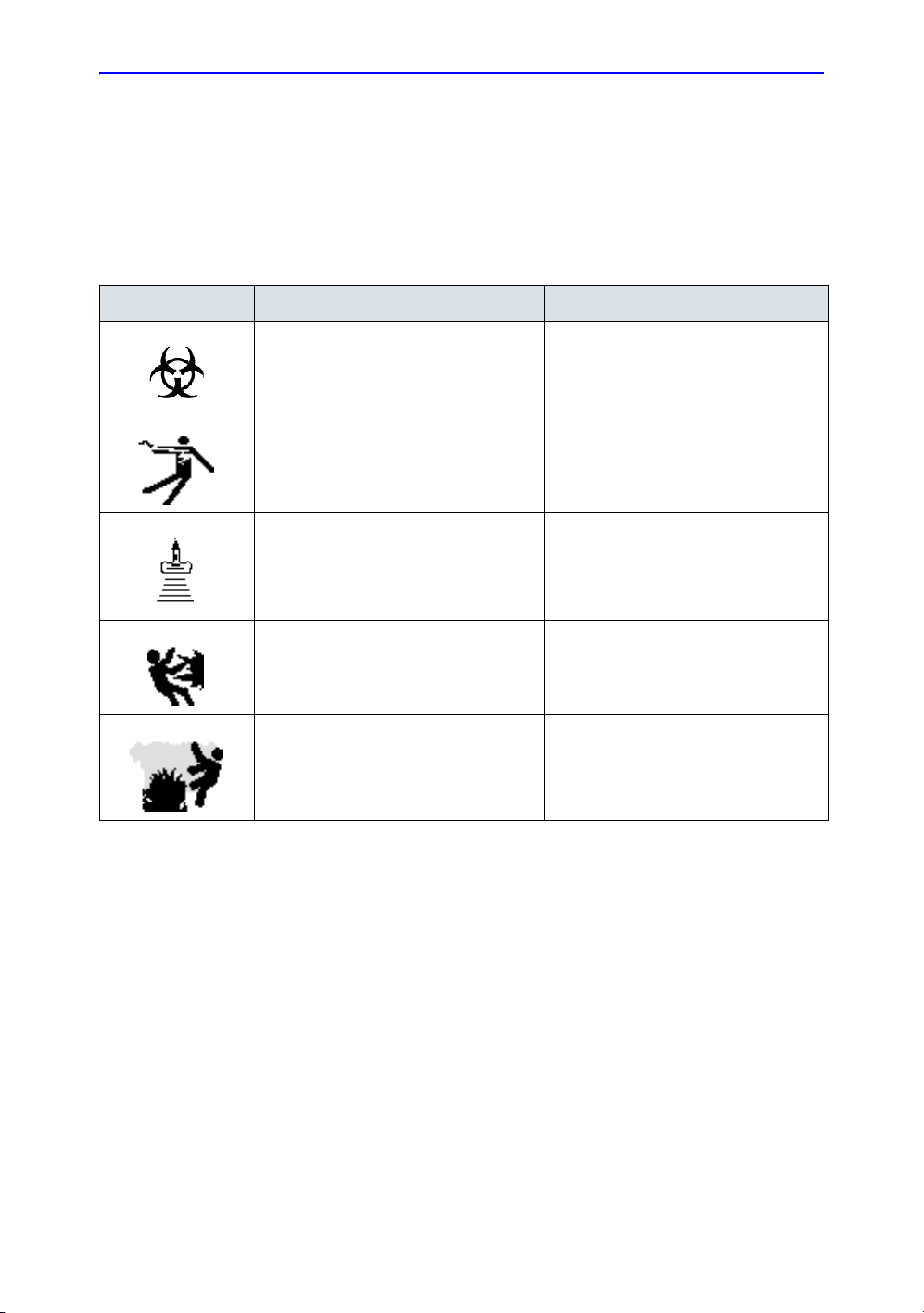
Hazard Symbols
Icon Description
Icon Potential Hazard Usage Source
Safety Precautions
Potential hazards are indicated by the following icons:
Table 2-1: Potential Hazards
• Patient/user infection due to
contaminated equipment.
• Electrical micro-shock to patient, e.g.,
ventricular
• Patient injury or tissue damage from
ultrasound radiation.
• Risk of explosion if used in the
presence of flammable anesthetics.
• Patient/user injury or adverse reaction
from fire or smoke.
• Patient/user injury from explosion and
fire.
• Cleaning and care
instructions
• Sheath and glove
guidelines
• Probes
• ECG, if applicable
• Connections to back
panel
• ALARA, the use of
Power Output following
the ‘as low as
reasonably achievable’
principle
• Flammable anesthetic
• Replacing fuses
• Outlet guidelines
ISO 7000
No. 0659
LOGIQ e Basic User Manual 2-3
Direction 5118586-100 Rev. 2
Page 34

Safety
Important Safety Considerations
The following topic headings (Patient Safety, and Equipment
and Personnel Safety) are intended to make the equipment user
aware of particular hazards associated with the use of this
equipment and the extent to which injury can occur if
precautions are not observed. Additional precautions may be
provided throughout the manual.
CAUTION
Improper use can result in serious injury. The user must be
thoroughly familiar with the instructions and potential hazards
involving ultrasound examination before attempting to use the
device. Training assistance is available from GE Medical
Systems if needed.
The equipment user is obligated to be familiar with these
concerns and avoid conditions that could result in injury.
2-4 LOGIQ e Basic User Manual
Direction 5118586-100 Rev. 2
Page 35

Patient Safety
Related Hazards
Safety Precautions
WARNING
Patient
identification
Diagnostic
information
The concerns listed can seriously affect the safety of patients
undergoing a diagnostic ultrasound examination.
Always include proper identification with all patient data and
verify the accuracy of the patient's name and ID numbers when
entering such data. Make sure correct patient ID is provided on
all recorded data and hard copy prints. Identification errors could
result in an incorrect diagnosis.
Equipment malfunction or incorrect settings can result in
measurement errors or failure to detect details within the image.
The equipment user must become thoroughly familiar with the
equipment operation in order to optimize its performance and
recognize possible malfunctions. Applications training is
available through the local GE representative. Added
confidence in the equipment operation can be gained by
establishing a quality assurance program.
LOGIQ e Basic User Manual 2-5
Direction 5118586-100 Rev. 2
Page 36

Safety
Related Hazards (continued)
Mechanical
hazards
Electrical
Hazard
CAUTION
CAUTION
The use of damaged probes can result in injury or increased risk
of infection. Inspect probes often for sharp, pointed, or rough
surface damage that could cause injury or tear protective
barriers. Become familiar with all instructions and precautions
provided with special purpose probes.
A damaged probe can also increase the risk of electric shock if
conductive solutions come in contact with internal live parts.
Inspect probes often for cracks or openings in the housing and
holes in and around the acoustic lens or other damage that
could allow liquid entry. Become familiar with the probe's use
and care precautions outlined in Probes and Biopsy.
Ultrasound transducers are sensitive instruments which can
easily be damaged by rough handling. Take extra care not to
drop transducers and avoid contact with sharp or abrasive
surfaces. A damaged housing, lens or cable can result in
patient injury or serious impairment or operation.
Ultrasound can produce harmful effects in tissue and
potentially result in patient injury. Always minimize exposure
time and keep ultrasound levels low when there is no medical
benefit. Use the principle of ALARA (A
A
chievable), increasing output only when needed to obtain
diagnostic image quality. Observe the acoustic output display
and be familiar with all controls affecting the output level. See
the Bioeffects section of the Acoustic Output chapter in the
Advanced Reference Manual for more information.
s Low As Reasonably
2-6 LOGIQ e Basic User Manual
Direction 5118586-100 Rev. 2
Page 37

Related Hazards (continued)
Training It is recommended that all users receive proper training in
applications before performing them in a clinical setting. Please
contact the local GE representative for training assistance.
ALARA training is provided by GE Application Specialists. The
ALARA education program for the clinical end-user covers basic
ultrasound principles, possible biological effects, the derivation
and meaning of the indices, ALARA principles, and examples of
specific applications of the ALARA principle.
Safety Precautions
LOGIQ e Basic User Manual 2-7
Direction 5118586-100 Rev. 2
Page 38

Safety
Equipment and Personnel Safety
Related Hazards
WARNING
WARNING
DANGER
Explosion
Hazard
This equipment contains dangerous voltages that are capable
of serious injury or death.
If any defects are observed or malfunctions occur, stop
operating the equipment and perform the proper action for the
patient. Inform a qualified service person and contact a Service
Representative for information.
There are no user serviceable components inside the console.
Refer all servicing to qualified service personnel only.
Only approved and recommended peripherals and accessories
should be used.
All peripherals and accessories must be securely mounted to
the LOGIQ e.
The concerns listed below can seriously affect the safety of
equipment and personnel during a diagnostic ultrasound
examination.
Risk of explosion if used in the presence of flammable
anesthetics.
2-8 LOGIQ e Basic User Manual
Direction 5118586-100 Rev. 2
Page 39
Related Hazards
(continued)
Safety Precautions
Electrical
Hazard
CAUTION
Smoke &
Fire Hazard
To avoid injury:
• Do not remove protective covers. No user serviceable
parts are inside. Refer servicing to qualified service
personnel.
• To assure adequate grounding, connect the attachment
plug to a reliable (hospital grade) grounding outlet (having
equalization conductor ).
• Never use any adaptor or converter of a three-prong-to-
two-prong type to connect with a mains power plug. The
protective earth connection will loosen.
• Do not place liquids on or above the console. Spilled liquid
may contact live parts and increase the risk of shock.
Do not use this equipment if a safety problem is known to exist.
Have the unit repaired and performance verified by qualified
service personnel before returning to use.
The system must be supplied from an adequately rated
electrical circuit. The capacity of the supply circuit must be as
specified.
Biological
Hazard
LOGIQ e Basic User Manual 2-9
Direction 5118586-100 Rev. 2
For patient and personnel safety, be aware of biological
hazards while performing invasive procedures. To avoid the
risk of disease transmission:
• Use protective barriers (gloves and probe sheaths)
whenever possible. Follow sterile procedures when
appropriate.
• Thoroughly clean probes and reusable accessories after
each patient examination and disinfect or sterilize as
needed. Refer to Probes and Biopsy for probe use and
care instructions.
• Follow all infection control policies established by your
office, department or institution as they apply to personnel
and equipment.
Page 40

Safety
Related Hazards
(continued)
CAUTION
CAUTION
CAUTION
Contact with natural rubber latex may cause a severe
anaphylactic reaction in persons sensitive to the natural latex
protein. Sensitive users and patients must avoid contact with
these items. Refer to package labeling to determine latex
content and FDA’s March 29, 1991 Medical Alert on latex
products.
Archived data is managed at the individual sites. Performing
data backup (to any device) is recommended.
DO NOT use high-frequency surgical equipment with the
LOGIQ e.
2-10 LOGIQ e Basic User Manual
Direction 5118586-100 Rev. 2
Page 41

Device Labels
Label Icon Description
The following table describes the purpose and location of safety
labels and other important information provided on the
equipment.
Label/Icon Purpose/Meaning Location
Safety Precautions
Table 2-2: Label Icons
Identification and Rating Plate • Manufacture’s name and address
• Date of manufacture
• Model and serial numbers
• Electrical ratings (Volts, Amps,
phase, and frequency)
Type/Class Label Used to indicate the degree of safety
IP Code (IPX1 or IPX8)
IPX1: FSU-2001
IPX8: MKF 2-MED GP26
or protection.
Indicates the degree of protection
provided by the enclosure per IEC60
529.
IPX1 cannot be used in an operating
room environment.
IPX8 can be used in an operating
room environment.
Type BF Applied Part (man in the box)
symbol is in accordance with IEC 87802-03.
Type CF Applied Part (heart in the
box) symbol is in accordance with IEC
60878-02-03.
“ATTENTION” - Consult
accompanying documents” is intended
to alert the user to refer to the operator
manual or other instructions when
complete information cannot be
provided on the label.
See Figure 2-3/Figure 2-4 for
location information. AC
Adapter Label.
Bottom of Footswitch
Beside the probe connector
ECG marked Type CF or
probes
Various
“CAUTION” - Dangerous voltage” (the
lightning flash with arrowhead) is used
to indicate electric shock hazards.
“ON” indicates the power on position
of the power switch.
CAUTION: This Power Switch DOES
NOT ISOLATE Mains Supply.
Various
See the Console Overview
section for location
information.
LOGIQ e Basic User Manual 2-11
Direction 5118586-100 Rev. 2
Page 42

Safety
Table 2-2: Label Icons
Label/Icon Purpose/Meaning Location
“Protective Earth” indicates the
protective earth (grounding) terminal.
NRTL Listing and Certification Mark is
used to designate conformance to
nationally recognized product safety
standards. The Mark bears the name
and/or logo of the testing laboratory,
product category, safety standard to
which conformity is assessed and a
control number.
Type CF Defib-Proof Applied Part
(heart in the box with paddle) symbol
is in accordance with IEC 60878-02-
06.
This symbol indicates that waste
electrical and electronic equipment
must not be disposed of as unsorted
municipal waste and must be collected
separately. Please contact an
authorized representative of the
manufacturer for information
concerning the decommissioning of
your equipment.
When closing the LCD cover, use
caution to avoid injuring hands or
fingers as there is a closing
mechanism which allows the LCD
cover to automatically close.
Inside of AC adapter
Bottom
ECG Module
Bottom
Bottom
2-12 LOGIQ e Basic User Manual
Direction 5118586-100 Rev. 2
Page 43

Label Icon Description (continued)
Classifications Type of protection against electric shock
• Class I Equipment—LOGIQ e Console with AC Adapter (*1)
Degree of protection against electric shock
Safety Precautions
• Type BF Applied part (*2)
• Type CF Applied part (*3)
(for Probes marked with BF symbol)
(for ECG marked with CF symbol)
Continuous Operation
System is Ordinary Equipment (IPX0)
Footswitch is IPX1 (FSU-2001) or IPX8 (MKF 2-MED GP26)
*1. Class I Equipment
EQUIPMENT in which protection against electric shock does not
rely on BASIC INSULATION only, but includes a protective earth
ground. This additional safety precaution prevents exposed
metal parts from becoming LIVE in the event of an insulation
failure.
*2. Type BF Applied Part
TYPE BF APPLIED PART providing a specified degree of
protection against electric shock, with particular regard to
allowable LEAKAGE CURRENT.
Table 2-3: Type BF Equipment
Normal Mode Single fault condition
Patient leakage current Less than 100 microA Less than 500 microA
*3. Type CF Applied Part
TYPE CF APPLIED PART providing a degree of protection
higher than that for Type BF Applied Part against electric shock
particularly regarding allowable LEAKAGE CURRENTS.
Table 2-4: Type CF Equipment
Normal Mode Single fault condition
Patient leakage current Less than 10 microA Less than 50 microA
LOGIQ e Basic User Manual 2-13
Direction 5118586-100 Rev. 2
Page 44

Safety
EMC (Electromagnetic Compatibility)
NOTE: This equipment generates, uses and can radiate radio
frequency energy. The equipment may cause radio frequency
interference to other medical and non-medical devices and radio
communications. To provide reasonable protection against such
interference, this product complies with emissions limits for a
Group 1, Class A Medical Devices Directive as stated in EN
60601-1-2. However, there is no guarantee that interference will
not occur in a particular installation.
NOTE: If this equipment is found to cause interference (which may be
determined by turning the equipment on and off), the user (or
qualified service personnel) should attempt to correct the
problem by one or more of the following measure(s):
• reorient or relocate the affected device(s)
• increase the separation between the equipment and the
affected device
• power the equipment from a source different from that of the
affected device
• consult the point of purchase or service representative for
further suggestions.
NOTE: The manufacturer is not responsible for any interference caused
NOTE: To comply with the regulations on electromagnetic interference
EMC Performance
by using other than recommended interconnect cables or by
unauthorized changes or modifications to this equipment.
Unauthorized changes or modifications could void the users’
authority to operate the equipment.
for a Class A FCC Device, all interconnect cables to peripheral
devices must be shielded and properly grounded. Use of cables
not properly shielded and grounded may result in the equipment
causing radio frequency interference in violation of the FCC
regulations.
All types of electronic equipment may characteristically cause
electromagnetic interference with other equipment, either
transmitted through air or connecting cables. The term EMC
(Electromagnetic Compatibility) indicates the capability of
equipment to curb electromagnetic influence from other
equipment and at the same time not affect other equipment with
similar electromagnetic radiation from itself.
2-14 LOGIQ e Basic User Manual
Direction 5118586-100 Rev. 2
Page 45

EMC Performance (continued)
Proper installation following the service manual is required in
order to achieve the full EMC performance of the product.
The product must be installed as stipulated in 4.2, Notice upon
Installation of Product.
In case of issues related to EMC, please call your service
personnel.
The manufacturer is not responsible for any interference caused
by using other than recommended interconnect cables or by
unauthorized changes or modifications to this equipment.
Unauthorized changes or modifications could void the users’
authority to operate the equipment.
Safety Precautions
CAUTION
Do not use devices which intentionally transmit RF signals
(cellular phones, transceivers, or radio controlled products),
other than those supplied by GE (wireless microphone,
broadband over power lines, for example) unless intended for
use with this system, in the vicinity of this equipment as it may
cause performance outside the published specifications.
Keep power to these devices turned off when near this
equipment.
Medical staff in charge of this equipment is required to instruct
technicians, patients and other people who may be around this
equipment to fully comply with the above regulation.
LOGIQ e Basic User Manual 2-15
Direction 5118586-100 Rev. 2
Page 46

Safety
EMC Performance (continued)
Portable and mobile radio communications equipment (e.g. twoway radio, cellular/cordless telephones and similar equipment)
should be used no closer to any part of this system, including
cables, than determined according to the following method:
Table 2-5: Portable and mobile radio communications equipment distance
requirements
Frequency Range: 150 kHz - 80 MHz 80 MHz - 800 MHz 800 MHz - 2.5 GHz
Calculation Method: d=[3.5/V
of P
Where: d= separation distance in meters, P = rated power of the transmitter, V
conducted RF, E
If the maximum
transmitter power in
watts is rated
5 2.6 2.6 5.2
20 5.2 5.2 10.5
100 12.0 12.0 24.0
= compliance value for radiated RF
1
The separation distance in meters should be
] square root
1
d = [3.5/E1] square root
of P
d = [7/E1] square root of
P
=compliance value for
1
2-16 LOGIQ e Basic User Manual
Direction 5118586-100 Rev. 2
Page 47

Notice upon Installation of Product
Separation distance and effect from fixed radio communications
equipment: field strengths from fixed transmitters, such as base
stations for radio (cellular/cordless) telephones and land mobile
radios, amateur radio, AM and FM radio broadcast, and TV
broadcast transmitter cannot be predicted theoretically with
accuracy. To assess the electromagnetic environment due to
fixed RF transmitters, an electromagnetic site survey should be
considered. If the measured field strength in the location in
which the ultrasound system is used exceeds the applicable RF
compliance level as stated in the immunity declaration, the
ultrasound system should be observed to verify normal
operation. If abnormal operation is observed, additional
measures may be necessary, such as re-orienting or relocating
the ultrasound system or using an RF shielded examination
room may be necessary.
1. Use either power supply cords provided by GE Medical
Systems or ones designated by GE Medical Systems.
Products equipped with a power source plug should be
plugged into the fixed power socket which has the protective
grounding conductor. Never use any adaptor or converter to
connect with a power source plug (e.g. three-prong-to-twoprong converter).
2. Locate the equipment as far away as possible from other
electronic equipment.
3. Be sure to use only the cables provided by or designated by
GE Medical Systems. Connect these cables following the
installation procedures (e.g. wire power cables separately
from signal cables).
4. Lay out the main equipment and other peripherals following
the installation procedures described in the Option
Installation manuals.
Safety Precautions
LOGIQ e Basic User Manual 2-17
Direction 5118586-100 Rev. 2
Page 48

Safety
General Notice
1. Designation of Peripheral Equipment Connectable to This
Product.
The equipment indicated in Chapter 18 can be hooked up to
the product without compromising its EMC performance.
Avoid using equipment not designated in the list. Failure to
comply with this instruction may result in poor EMC
performance of the product.
2. Notice against User Modification
The user should never modify this product. User
modifications may cause degradation in EMC performance.
Modification of the product includes changes in:
a. Cables (length, material, wiring, etc.)
b. System installation/layout
c. System configuration/components
d. Securing system parts (cover open/close, cover
screwing)
2-18 LOGIQ e Basic User Manual
Direction 5118586-100 Rev. 2
Page 49

Peripheral Update for EC countries
The following is intended to provide the users in EC countries
with updated information concerning the connection of the
LOGIQ e to image recording and other devices or
communication networks.
Safety Precautions
Peripheral used in
the patient
environment
CAUTION
The LOGIQ e has been verified for overall safety, compatibility
and compliance with the following on-board image recording
devices:
• Sony UP-D897MD B/W Printer
• Sony UP-D23MD Color Printer
The LOGIQ e may also be used safely while connected to
devices other than those recommended above if the devices
and their specifications, installation, and interconnection with the
system conform to the requirements of IEC/EN 60601-1-1.
The connection of equipment or transmission networks other
than as specified in the user instructions can result in an
electric shock hazard or equipment malfunction. Substitute or
alternate equipment and connections requires verification of
compatibility and conformity to IEC/EN 60601-1-1 by the
installer. Equipment modifications and possible resulting
malfunctions and electromagnetic interference are the
responsibility of the owner.
General precautions for installing an alternate off-board, remote
device or a network would include:
1. The added device(s) must have appropriate safety standard
conformance and CE Marking.
2. There must be adequate mechanical mounting of the device
and stability of the combination.
3. Risk and leakage current of the combination must comply
with IEC/EN 60601-1.
4. Electromagnetic emissions and immunity of the combination
must conform to IEC/EN 60601-1-2.
LOGIQ e Basic User Manual 2-19
Direction 5118586-100 Rev. 2
Page 50

Safety
Peripheral Update for EC countries (continued)
Peripheral used in
the non-patient
environment
The LOGIQ e has also been verified for compatibility, and
compliance for connection to a local area network (LAN) via a
wireless LAN, provided the LAN components are IEC/EN 60950
compliant.
The LOGIQ e has also been verified for compatibility, and
compliance for connection to a DVD-RW via the system USB
port, provided the DVD-RW is IEC/EN 60950 compliant.
General precautions for installing an alternate off-board, remote
device or a network would include:
1. The added device(s) must have appropriate safety standard
conformance and CE Marking.
2. The added device(s) must be used for their intended
purpose having a compatible interface.
2-20 LOGIQ e Basic User Manual
Direction 5118586-100 Rev. 2
Page 51

Safety Precautions
Declaration of Emissions
This system is suitable for use in the following environment. The
user must assure that it is used only in the electromagnetic
environment as specified.
Table 2-6: Declaration of Emissions
Emission Type Compliance Electromagnetic Environment
CISPR 11
RF Emissions
Group 1
Class A
This system uses RF energy only for its internal function.
Therefore, RF emissions are very low and are not likely to cause
any interference in nearby electronic equipment. It is suitable for
use in all establishments, other than domestic establishments
and those directly connected to the public low-voltage power
supply network that supplies buildings used for domestic
purposes.
LOGIQ e Basic User Manual 2-21
Direction 5118586-100 Rev. 2
Page 52

Safety
Declaration of Immunity
This system is suitable for use in the following environment. The
user must assure that the system is used according to the
specified guidance and only in the electromagnetic environment
listed.
Table 2-7: Declaration of Immunity
Immunity
Type
IEC 61000-4-2
Static discharge
(ESD)
IEC 61000-4-4
Electrical fast
transient/burst
IEC 61000-4-5
Surge Immunity
IEC 61000-4-11
Voltage dips,
short
interruptions and
voltage
variations on
mains supply
IEC 61000-4-8
Power
frequency (50/
60 Hz) magnetic
field
IEC 61000-4-6
Conducted RF
IEC 61000-4-3
Radiated RF
Equipment
Capability
± 6 kV contact
± 8 kV air
± 2 kV for mains
± 1 kV for SIP/
SOP
± 1 kV differential
± 2 kV common
(> 95% dip)
< 50
T
for 0.5 cycle;
(60 0ip) for 5
400
T
cycles;
700
(30 0ip) for
T
25 cycles;
< 50
(>95% dip)
T
for 5 sec
3 A/m 3 A/m
3 V
RMS
150 kHz - 80 MHz
3 V/m
80 MHz - 2.5 GHz
Acceptable Level
± 6 kV contact
± 8 kV air
± 2 kV for mains
± 1 kV for SIP/SOP
± 1 kV differential
± 2 kV common
< 50
0.5 cycle;
400
cycles;
700
cycles;
< 50
sec
3 V
RMS
150 kHz - 80 MHz
3 V/m
80 MHz - 2.5 GHz
Regulatory
(> 95% dip) for
T
(60 0ip) for 5
T
(30 0ip) for 25
T
(>95% dip) for 5
T
EMC Environment and
Guidance
Floors should be wood, concrete, or
ceramic tile. If floors are covered with
synthetic material, the relative
humidity should be at least 30%.
Mains power quality should be that of
a typical commercial and/or hospital
environment. If the user requires
continued operation during power
mains interruptions, it is
recommended that the system be
powered from a UPS or a battery.
NOTE: UT is the a.c. mains voltage
prior to application of the test level.
Power frequency magnetic fields
should be at levels characteristic of a
typical location in a typical commercial
and/or hospital environment.
Separation distance to radio
communication equipment must be
maintained according to the method
below. Interference may occur in the
vicinity of equipment marked with the
symbol:
Image degradation or interference
may occur due to conducted RF noise
on the equipment mains power supply
or other signal cable. Such
interference is easily recognized and
distinguishable from patient anatomy
and physiological waveforms.
Interference of this type may delay the
examination without affecting
diagnostic accuracy. Additional mains/
signal RF isolation or filtering may be
needed if this type interference occurs
frequently.
NOTE: These guidelines may not apply in all situations. Electromagnetic propagation is affected by
absorption and reflection from structures, objects, and people. If noise generated from other electronic
equipment is near the probe’s center frequency, noise may appear on the image. Good power line isolation
is required.
2-22 LOGIQ e Basic User Manual
Direction 5118586-100 Rev. 2
Page 53

Patient Environmental Devices
Safety Precautions
Figure 2-1. Patient Environmental Devices
1. Left side:
• 2 USB Ports—Peripheral devices, Printers (B/W, Color
and USB), Memory Stick, Footswitch, Wireless LAN
Adapter, USB Hub, ECG
• 1 Earphone Port
2. Bottom side: Lithium-ion battery port
3. Right side: Probe port, Security lock
4. Rear panel:
• 1 VGA Port.
• 1 Network Port
• 1 Docking Port
LOGIQ e Basic User Manual 2-23
Direction 5118586-100 Rev. 2
Page 54

Safety
Acceptable Devices
The Patient Environmental devices shown on the previous page
are specified to be suitable for use within the PATIENT
ENVIRONMENT.
CAUTION
Unapproved Devices
CAUTION
DO NOT connect any probes or accessories without approval
by GE within the PATIENT ENVIRONMENT.
See ‘Peripheral Update for EC countries’ on page 2-19 for
more information.
DO NOT use unapproved devices.
If devices are connected without the approval of GE, the
warranty will be INVALID.
Any device connected to the LOGIQ e must conform to one or
more of the requirements listed below:
1. IEC standard or equivalent standards appropriate to
devices.
2. The devices shall be connected to PROTECTIVE EARTH
(GROUND).
Accessories, Options, Supplies
CAUTION
Unsafe operation or malfunction may result. Use only the
accessories, options and supplies approved or recommended
in these instructions for use.
2-24 LOGIQ e Basic User Manual
Direction 5118586-100 Rev. 2
Page 55

Acoustic Output
Located on the upper right section of the system display monitor,
the acoustic output display provides the operator with real-time
indication of acoustic levels being generated by the system. See
the Acoustic Output chapter in the Advanced Reference Manual
for more information. This display is based on NEMA/AIUM
Standards for Real-time Display of Thermal and Mechanic
Acoustic Output Indices on Diagnostic Ultrasound Equipment.
Acoustic Output Display Specifications
The display consists of three parts: Thermal Index (TI),
Mechanical Index (MI), and a relative Acoustic Output (AO)
value. Although not part of the NEMA/AIUM standard, the AO
value informs the user of where the system is operating within
the range of available output.
The TI and MI are displayed at all times. The TI display starts at
a value of 0.0 and increments in steps of 0.1 The MI display
values between 0 and 0.4 increment in steps of 0.01 and for
values greater than 0.4, increments in steps of 0.1.
Safety Precautions
Thermal Index Depending on the examination and type of tissue involved, the
TI parameter will be one of three types:
• Soft Tissue Thermal Index (TIS). Used when imaging soft
tissue only, it provides an estimate of potential temperature
increase in soft tissue.
• Bone Thermal Index (TIB). Used when bone is near the
focus of the image as in the third trimester OB examination,
it provides an estimate of potential temperature increase in
the bone or adjacent soft tissue.
• Cranial Bone Thermal Index (TIC). Used when bone is
near the skin surface as in transcranial examination, it
provides an estimate of potential temperature increase in
the bone or adjacent soft tissue.
LOGIQ e Basic User Manual 2-25
Direction 5118586-100 Rev. 2
Page 56

Safety
Acoustic Output Display Specifications (continued)
Mechanical Index MI recognizes the importance of non-thermal processes,
cavitation in particular, and the Index is an attempt to indicate
the probability that they might occur within the tissue.
Changing the
Thermal Index
Type
You can select the displayed TI type on Utility -> Imaging -> BMode. This preset is application dependent so each application
could specify a different TI type.
Display precision is ±0.1 and accuracy is ±50%. Accuracy of the
power output displayed value on the Top/Sub Menu is ±2% in BMode and ±10% in all other modes.
Controls Affecting Acoustic Output
The potential for producing mechanical bioeffects (MI) or
thermal bioeffects (TI) can be influenced by certain controls.
Direct. The Acoustic Output control has the most significant
effect on Acoustic Output.
Indirect. Indirect effects may occur when adjusting controls.
Controls that can influence MI and TI are detailed under the
Bioeffects portion of each control in the Optimizing the Image
chapter.
Always observe the Acoustic Output display for possible effects.
2-26 LOGIQ e Basic User Manual
Direction 5118586-100 Rev. 2
Page 57

Best practices while scanning
A
Safety Precautions
HINTS
NOTE: Refer to the sections in Chapter 5 for a complete discussion of
WARNING
coustic
Output
Hazard
Raise the Acoustic Output only after attempting image
optimization with controls that have no effect on Acoustic
Output, such as Gain and TGC.
each control.
Be sure to have read and understood control explanations for
each mode used before attempting to adjust the Acoustic
Output control or any control that can effect Acoustic Output.
Use the minimum necessary acoustic output to get the best
diagnostic image or measurement during an examination.
Begin the exam with the probe that provides an optimum focal
depth and penetration.
Acoustic Output Default Levels
In order to assure that an exam does not start at a high output
level, the LOGIQ e initiates scanning at a reduced default output
level. This reduced level is preset programmable and depends
upon the exam category and probe selected. It takes effect
when the system is powered on or New Patient is selected.
To modify acoustic output, adjust the Power Output level on the
Top/Sub Menu.
LOGIQ e Basic User Manual 2-27
Direction 5118586-100 Rev. 2
Page 58

Safety
Warning Label Locations
LOGIQ e warning labels are provided in English.
Figure 2-2. Label location explanations
Table 2-8: Label Location Explanations
1. Possible shock hazard. Do not remove covers
or panels. No user serviceable parts are inside.
Refer servicing to qualified service personnel.
2. Do not use the following devices near this
equipment: cellular phone, radio receiver,
mobile radio transimitter, radio controlled toy,
etc. Use of these devices near this equipment
could cause this equipment to perform outside
the published specifications. Keep power to
these devices turned off when near this
equipment.
3. Be careful of static
4. Prescription Device (For U.S.A. Only)
5. The CE Mark of Conformity indicates this
equipment conforms with the Council Directive
93/42/EEC.
6. WEEE Label
7. CISPR CAUTION: The LOGIQ e conforms to
the CISPR11, Group 1, Class A of the
international standard for Electromagnetic
disturbance characteristics.
2-28 LOGIQ e Basic User Manual
Direction 5118586-100 Rev. 2
Page 59
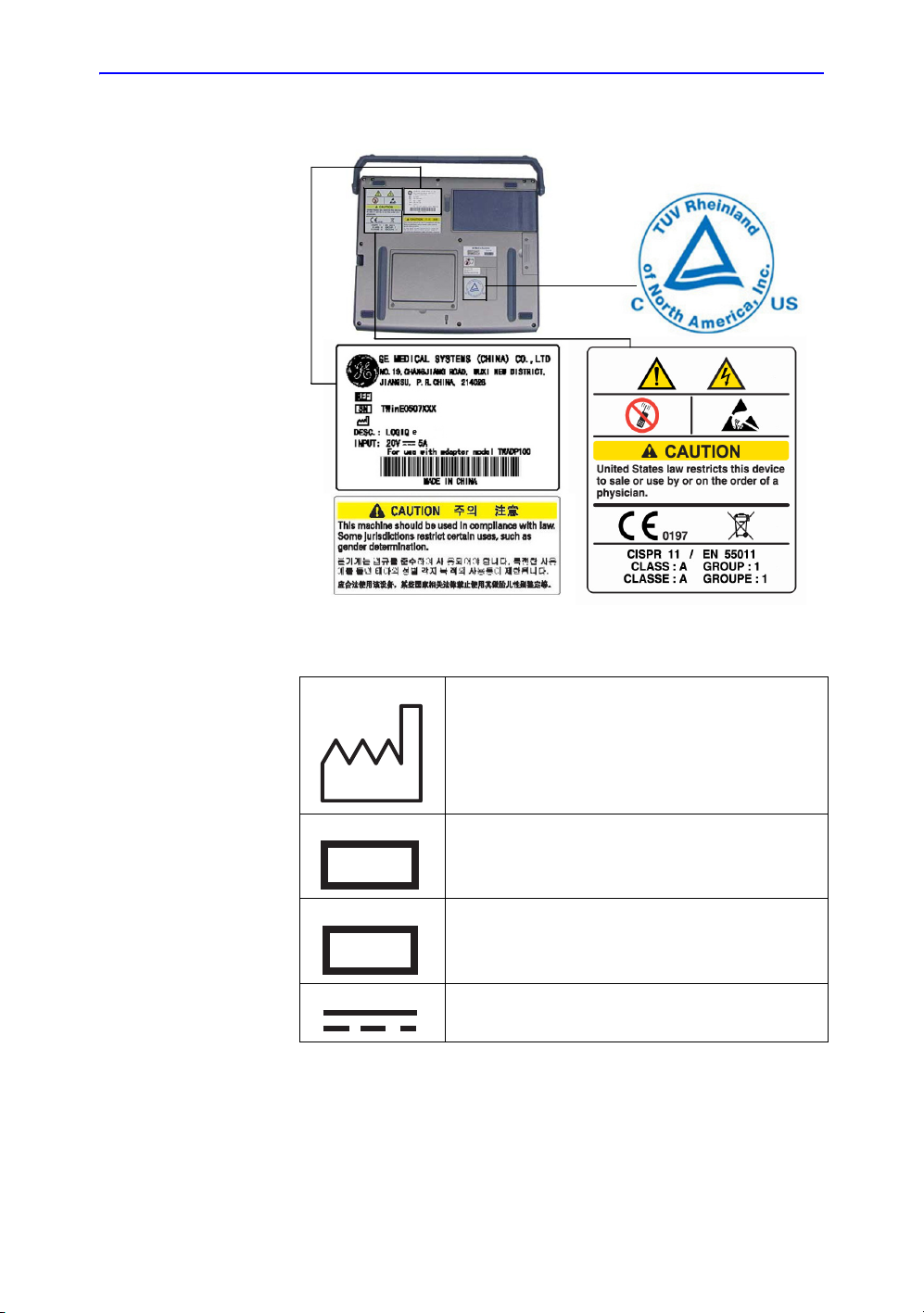
Warning Label Locations (continued)
REF
SN
Safety Precautions
Figure 2-3. TUV and Identification/Rating Plate Label Location
Table 2-9: Rating Plate Explanations
Date of manufacture: The date could be a year, year
and month, or year, month and day, as appropriate.
See ISO 8601 for date formats.
Catalog or model number
REF
Serial number
SN
Direct Current: For products to be powered from a DC
supply
LOGIQ e Basic User Manual 2-29
Direction 5118586-100 Rev. 2
Page 60

Safety
Warning Label Locations (continued)
Figure 2-4. AC Adapter Label
Figure 2-5. Battery Label
2-30 LOGIQ e Basic User Manual
Direction 5118586-100 Rev. 2
Page 61

Chapter 3
Preparing the System for Use
Describes the site requirements, console overview,
system positioning/transporting, powering on the
system, adjusting the display monitor, probes and
operator controls.
LOGIQ e Basic User Manual 3-1
Direction 5118586-100 Rev. 2
Page 62

Preparing the System for Use
Introduction
NOTE: Only qualified physicians or sonographers should perform
ultrasound scanning on human subjects for medical diagnostic
reasons. Request training, if needed.
The LOGIQ e does not contain any operator serviceable internal
components. Ensure that unauthorized personnel do not tamper
with the unit.
Perform regular preventive maintenance. See ‘System Care and
Maintenance’ on page 18-9 for more information.
Maintain a clean environment. Turn off, and if possible,
disconnect the system before cleaning the unit. See ‘Cleaning
the system’ on page 18-11 for more information.
Site Requirements
Never set liquids on the unit to ensure that liquid does not drip
into the control panel or unit.
3-2 LOGIQ e Basic User Manual
Direction 5118586-100 Rev. 2
Page 63

Site Requirements
Before the system arrives
NOTICE This medical equipment is approved, in terms of the prevention
of radio wave interference, to be used in hospitals, clinics and
other institutions which are environmentally qualified. The use of
this equipment in an inappropriate environment may cause
some electronic interference to radios and televisions around
the equipment.
Ensure that the following is provided for the new system:
• A separate power outlet with a 6 amp circuit breaker for 220240 VAC or a 10 amp circuit breaker for 100-120 VAC.
• Take precautions to ensure that the console is protected
from electromagnetic interference.
Precautions include:
• Operate the console at least 15 feet away from motors,
typewriters, elevators, and other sources of strong
electromagnetic radiation.
• Operation in an enclosed area (wood, plaster or
concrete walls, floors and ceilings) helps prevent
electromagnetic interference.
• Special shielding may be required if the console is to be
operated in the vicinity of radio broadcast equipment.
LOGIQ e Basic User Manual 3-3
Direction 5118586-100 Rev. 2
Page 64

Preparing the System for Use
Environmental Requirements
The system should be operated, stored, or transported within
the parameters outlined below. Either its operational
environment must be constantly maintained or the unit must be
turned off.
Table 3-1: System Environmental Requirements
Operational Storage Transport
Temperature 10 - 40 degrees C
50 - 104 degrees F
Humidity 30 - 75% non-condensing 10 - 90% non-condensing 10 - 90% non-condensing
Pressure 700 - 1060hPa 700 - 1060hPa 700 - 1060hPa
-5 - 50 degrees C
23 - 122 degrees F
-5 - 50 degrees C
23 - 122 degrees F
Acclimation Time
After being transported, the unit requires one hour for each 2.5
degree increment its temperature is below 10 degree C or above
40 degree C.
Table 3-2: System Acclimation Time Chart
Degree C 60 55 50 45 40 35 30 25 20 15 10
Degree F 140 131 122 113 104 95 86 77 68 59 50
hours 86420000000
Degree C 5 0 -5 -10 -15 -20 -25 -30 -35 -40
Degree F 41 32 23 14 5 -4 -13 -22 -31 -40
hours 2 4 6 8 10 12 14 16 18 20
3-4 LOGIQ e Basic User Manual
Direction 5118586-100 Rev. 2
Page 65

Console graphics
Console Overview
Console Overview
The following are illustrations of the console:
Figure 3-1. LOGIQ e System (opened view)
1. Handle
2. Soft Menu (use same as menu key)
3. LCD
4. Alphanumeric keys
5. Control Panel
LOGIQ e Basic User Manual 3-5
Direction 5118586-100 Rev. 2
Page 66

Preparing the System for Use
Console graphics (continued)
Figure 3-2. LOGIQ e System (side views)
CAUTION
Do not push objects into air vents and openings of LOGIQ e.
Doing so can cause fire or electric shock by shorting out interior
components.
3-6 LOGIQ e Basic User Manual
Direction 5118586-100 Rev. 2
Page 67

Battery
Console Overview
The lithium ion battery provides power when an AC power
source is not available. A battery in the battery bay is standard
with the LOGIQ e. Lithium ion batteries last longer than
conventional batteries and do not require replacement as often.
You can expect one hour of battery life with a single fully
charged battery.
The lithium ion technology used in your LOGIQ e’s battery is
significantly less hazardous to the environment than the lithium
metal technology used in some other batteries (such as watch
batteries). Used batteries should not be placed with common
household waste products. Contact local authorities for the
location of a chemical waste collection program nearest you.
NOTE: The battery is designed to work with LOGIQ e systems only.
Only use the batteries authorized by GE.
WARNING
• The battery has a safety device. Do not disassemble or
alter the battery.
• Charge the batteries only when the ambient temperature is
between 0 and 50 degrees C (32 and 122 degrees F) and
discharge the batteries between 0 and 60 degrees C
(32 and 140 degrees F).
• Do not short-circuit the battery by directly connecting the
negative terminals with metal objects.
• Do not heat the battery or discard it in a fire.
• Do not expose the battery to temperature over
60 degrees C (140 degrees F). Keep it away from fire and
other heat sources.
• Do not charge the battery near a heat source, such as a
fire or heater.
• Do not leave the battery in direct sunlight.
• Do not pierce the battery with a sharp object, hit it, or step
on it.
• Do not use a damaged battery.
• Do not solder a battery.
• Do not connect the battery to an electrical power outlet.
LOGIQ e Basic User Manual 3-7
Direction 5118586-100 Rev. 2
Page 68

Preparing the System for Use
Battery (continued)
WARNING
CAUTION
If the LOGIQ e is not being used on a monthly basis, the
battery needs to be removed during the lengthy non-use
period.
To avoid the battery bursting, igniting, or fumes from the battery
causing equipment damage, observe the following precautions:
• Do not immerse the battery in water or allow it to get wet.
• Do not put the battery into a microwave oven or
pressurized container.
• If the battery leaks or emits an odor, remove it from all
possible flammable sources.
• If the battery emits an odor or heat, is deformed or
discolored, or in a way appears abnormal during use,
recharging or storage, immediately remove it and stop
using it. If you have any questions about the battery,
consult GE or your local representative.
• Short term (less than one month) storage of battery pack:
• Store the battery in a temperature range between
0 degrees C (32 degrees F) and 50 degrees C
(122 degrees F).
3-8 LOGIQ e Basic User Manual
Direction 5118586-100 Rev. 2
Page 69

Battery (continued)
Console Overview
CAUTION
• Long term (3 months or more) storage of battery pack:
• Store the battery in a temperature range between
-20 degrees C (-4 degrees F) and 45 degrees C
(113 degrees F)
• Upon receipt of the LOGIQ e and before first time
usage, it is highly recommended that the customer
performs one full discharge/charge cycle. If the battery
has not been used for >2 months, the customer is
recommended to perform one full discharge/charge
cycle. It is also recommended to store the battery in a
shady and cool area with FCC (full current capacity).
• One Full Discharge/Charge Cycle Process:
1. Full discharge of battery to let the LOGIQ e
automatically shut down.
2. Charge the LOGIQ e to 100% FCC (full current
capacity).
3. Discharge of LOGIQ e for complete shut down
(takes one hour for discharge).
• When storing packs for more than 6 months, charge
the pack at least once during the 6 month timeframe to
prevent leakage and deterioration in performance.
• Use only GE recognized batteries.
LOGIQ e Basic User Manual 3-9
Direction 5118586-100 Rev. 2
Page 70

Preparing the System for Use
Battery (continued)
View current
battery status
When the system is running, there is a battery icon in the system
status bar.
Figure 3-3. Battery icon
When you select this icon, the following appears:
Figure 3-4. Battery Status Message
Current power source–displays the current power source, AC
power or Battery.
Total battery power remaining–displays the current power
remaining capacity. When there is no battery, “Battery not
present” appears. When using a battery, it’s current capacity in
percent appears “current capacity (unit: percent)”. If the battery
is not in use, it states “current capacity (charging)”.
Warning information–displays warning information when battery
power is low. See Figure 3-5.
3-10 LOGIQ e Basic User Manual
Direction 5118586-100 Rev. 2
Page 71

Battery (continued)
Console Overview
Battery power low
warning
NOTE: When the battery power is low and the user cannot charge the
AC Adapter
If the battery is in use and the battery power is low, a warning
message appears to warn the user that the battery power is low
and that it needs to be charged.
Figure 3-5. Low battery power warning
battery in time, the system automatically shuts down in 2
minutes. This protects the whole system. You need to save all
unsaved data before the system shuts down or you may lose
useful information.
CAUTION
LOGIQ e Basic User Manual 3-11
Direction 5118586-100 Rev. 2
Do not use an AC adapter without approval by GE.
Be sure that nothing rests on the AC adapter’s power cable
and that the cable is not located where it can be tripped over or
stepped on.
Place the AC adapter in a ventilated area, such as a desk,
when you use it to run LOGIQ e. Do not cover the AC adapter
with paper or other items that will reduce cooling; do not use
the AC adapter inside a carrying case.
Page 72

Preparing the System for Use
Peripheral/Accessory Connection
Peripheral/Accessory Connector Panel
LOGIQ e peripherals and accessories can be properly
connected using the rear and side panels.
CAUTION
CAUTION
Each outer (case) ground line of peripheral/accessory
connectors are Earth Grounded.
Signal ground lines are Not Isolated.
For compatiblity reasons, use only GE approved probes,
peripherals or accessories.
DO NOT connect any probes or accessories without approval
by GE.
Figure 3-6. Peripheral/Accessory Connector Panel
1. 2 USB Ports for Printers (B/W, Color and USB), Memory
Stick, Footswitch, DVD-RW, Wireless LAN Adapter, USB
Hub, ECG
2. Earphone Port
3. Port for DC In (AC Adapter)
4. Docking Port
5. VGA Port
6. Network Port
3-12 LOGIQ e Basic User Manual
Direction 5118586-100 Rev. 2
Page 73

Peripheral/Accessory Connector Panel (continued)
NOTE: The USB devices should be connected to the LOGIQ e first,
power on the USB devices before turning on the LOGIQ e.
Console Overview
CAUTION
Footswitch (Option)
CAUTION
The connection of equipment or transmission networks other
than as specified in these instructions can result in electric
shock hazard. Alternate connections will require verification of
compatibility and conformity to IEC/EN 60601-1-1 by the
installer.
Use only the GE recommended footswitch. The footswitch may
be used as select keys.
Use the footswitch to freeze the real-time image. Use the
footswitch as P1, P2 and P3 buttons on the keyboard.
The footswitch connection is located on the USB port.
Do NOT connect the footswitch to USB Hub.
LOGIQ e Basic User Manual 3-13
Direction 5118586-100 Rev. 2
Page 74

Preparing the System for Use
ECG (Option)
CAUTION
CAUTION
• ECG electrodes should not make contact with other
conductive parts, including earth.
• After the defibrillator stimulates the patient, the ECG needs
4 to 5 seconds for recovery.
• The quality of the ECG trace depends on the stability and
conductivity of the electrodes during the test, especially
during high stages when the patient’s movements can
cause artifacts.
• Make sure that the lead wires do not swing.
The device is not waterproof. Do not expose the device to
water or any kind of liquid. Maintain in a dry place:
• The exterior of the recorder may be wiped clean with a soft
cloth. Do not use harsh cleaning agents to clean the unit.
Do not immerse the unit in any liquid.
• Clean the cables with a hospital approved cleaning
procedure such as those recommended by AAMI or
AORN. Wiping the cables with a solution of soap and water
followed by a rinse with water is a simple yet effective
method to clean the cables. Do not immerse cables in
water.
• Worn or damaged patient cables are the most common
cause of poor ECG signals. ECG signals (or wave
patterns) that consistently contain noise or artifact may
suggest need for ECG wire or cable replacement.
• Store the device in a dry place.
• Always protect the recorder from coming into contact with
moisture. In rain or snow conditions, protect the recorder
from bad weather elements by wearing the recorder inside
a coat.
NOTE: For information on ECG installation, refer to the LOGIQ e
Peripheral Installation Instruction.
3-14 LOGIQ e Basic User Manual
Direction 5118586-100 Rev. 2
Page 75

ECG (Option) (continued)
Console Overview
Electrode
Placement
The ECG cable has triple color-coded electrode connectors on
the end. Each electrode cable hooks up to the appropriate stickon electrode by a color-coded clip type connector.
Table 3-3: ECG Lead Placement
Patient Cable Marking
Lead
I RA (White) R (Red) Right Arm
II LA (Black) L (Yellow) Left Arm
III RL (Green) N (Black) Right Leg
Position on PatientAHA IEC
Table 3-4: ECG Technical Specifications
Feature Specification
Size [mm] 85x45x22 mm (+/- 0.5 mm)
Power consumption USB 5V supply
Current 80 mA +/-10%
ECG samples/sec 1000
A/D bits 12 (2.44 uV/LSB)
Defibrillation protection Built in
Patient Leads Detachable 3 leads (IEC or AHA)
CMMR > 80 dB
Input resistance > 10 Mohm
Signal snamic range 10mV (-5 to +5 mV)
Patient isolation 4000V
Patient leakage current < 10 uA
Frequency range (-3db) 0.05 - 150 Hz
Safety standard IEC 60601-1, EN 60601-2, IEC 60601-2-27
Operating temperature 0 to 70 degrees C
Storing temperature (-65) to 150 degrees C
Humidity < 80%
LOGIQ e Basic User Manual 3-15
Direction 5118586-100 Rev. 2
Page 76

Preparing the System for Use
Peripherals Connection
1. Connect the B/W printer to the system. The B/W printer can
be properly connected using the USB Port 1 or 2.
2. Connect the DVD-RW to the system. The DVD-RW can be
properly connected using the USB Port 1 or 2.
Figure 3-7. B/W Printer Connection
Figure 3-8. DVD-RW Connection
NOTE: Do not connect the DVD-RW to the system while scanning.
3-16 LOGIQ e Basic User Manual
Direction 5118586-100 Rev. 2
Page 77
Peripherals Connection (continued)
3. Connect the footswitch to the system. The footswitch can be
properly connected using the USB Port 1 or 2.
Figure 3-9. Footswitch Connection
4. Connect the Wireless LAN Adapter to the system. The
wireless LAN adapter can be properly connected using the
USB Port 1 or 2.
Console Overview
Figure 3-10. Wireless LAN Connection
LOGIQ e Basic User Manual 3-17
Direction 5118586-100 Rev. 2
Page 78

Preparing the System for Use
Peripherals Connection (continued)
5. Connect the USB Memory to the system. The USB Memory
can be properly connected using USB Port 1 or 2.
Figure 3-11. USB Memory Connection
6. Connect the HP460 Printer to the system. The HP460
Printer can be properly connected using USB Port 1 or 2.
Figure 3-12. HP460 Printer Connection
3-18 LOGIQ e Basic User Manual
Direction 5118586-100 Rev. 2
Page 79
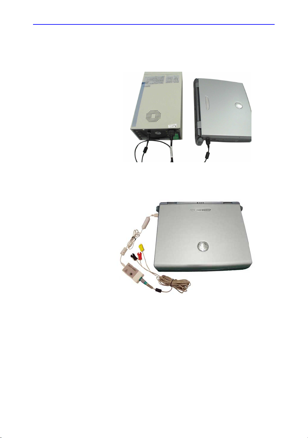
Peripherals Connection (continued)
7. Connect the Color Printer to the system. The Color Printer
can be properly connected using USB Port 1 or 2.
Figure 3-13. Color Printer Connection
8. Connect the ECG to the system. The ECG can be properly
connected using USB Port 1 or 2.
Console Overview
Figure 3-14. ECG Connection
NOTE: Please refer to the operation manual of each peripheral for
information needed by the user to operate the system safely.
For detailed installation information, please refer to the LOGIQ e
Peripheral Installation Instruction manual.
LOGIQ e Basic User Manual 3-19
Direction 5118586-100 Rev. 2
Page 80

Preparing the System for Use
System Positioning/Transporting
Moving the System
When moving or transporting the system, follow the precautions
below to ensure the maximum safety for personnel, the system,
and other equipment.
Before moving the system
1. Shut down the system.See ‘Power Off’ on page 3-29 for
more information.
2. Unplug the power cord (if the system is plugged in).
3. Disconnect all cables from off-board peripheral devices
(external printer, etc.) from the console.
To prevent damage to the Power Cord, DO NOT pull
excessively on the cord or make sharp bends while
wrapping.
4. Store all probes in their original cases or in soft cloth or foam
to prevent damage.
5. Store sufficient gel and other essential accessories in the
special storage case.
3-20 LOGIQ e Basic User Manual
Direction 5118586-100 Rev. 2
Page 81

When moving the system
1. Always use the handle to move the system.
System Positioning/Transporting
CAUTION
The system weighs approximately 4.6 kg. To avoid possible
injury and equipment damage:
• Do not let the system strike walls or door frame.
• Limit movement to a slow careful walk.
LOGIQ e Basic User Manual 3-21
Direction 5118586-100 Rev. 2
Page 82

Preparing the System for Use
Transporting the System
Use extra care when transporting the system using vehicles. In
addition to the instructions used when moving the system (See
‘Moving the System’ on page 3-20 for more information.), also
perform the following:
1. Before transporting, place the system in its special storage
case.
2. Ensure that the system is firmly secured while inside the
vehicle.
3. Secure system with straps or as directed otherwise to
prevent motion during transport.
3-22 LOGIQ e Basic User Manual
Direction 5118586-100 Rev. 2
Page 83

Attaching the Security Cable
To ensure that the LOGIQ e is not removed from the premises,
attach the security cable.
1. Wrap the cable around an imovable object.
2. Make sure and rotate the key to the unlocked position (to
the right).
3. Insert the lock into the security slot to the system’s side
cover.
System Positioning/Transporting
Figure 3-15. Security Cable
Figure 3-16. LOGIQ e with Security Cable
4. Rotate the key to the locked position (to the left).
LOGIQ e Basic User Manual 3-23
Direction 5118586-100 Rev. 2
Page 84

Preparing the System for Use
Powering the System
Connecting and Using the System
To connect the system to the electrical supply:
1. Ensure that the wall outlet is of the appropriate type.
2. Plug the AC adapter connector on the LOGIQ e.
3. Push the power plug securely into the wall outlet.
CAUTION
WARNING
WARNING
WARNING
Use caution to ensure that the power cable does not
disconnect during system use.
If the system is accidentally unplugged, data may be lost.
The system should rest on the handle to allow an air gap to
prevent overheating.
DO NOT use the LOGIQ e on plastic foam, paper or similar
type surfaces. The system could overheat and slow down.
Ensure that the LOGIQ e is on a sturdy, heat resistant surface.
To avoid risk of fire, the system power must be supplied from a
separate, properly rated outlet. See ‘Before the system arrives’
on page 3-3 for more information.
Under no circumstances should the AC power plug be altered,
changed, or adapted to a configuration rated less than
specified. Never use an extension cord or adapter plug.
To help assure grounding reliability, connect to a “hospital
grade” or “hospital only” grounded power outlet.
3-24 LOGIQ e Basic User Manual
Direction 5118586-100 Rev. 2
Page 85

Powering the System
Connecting and Using the System (continued)
Table 3-5: Example Plug and Outlet Configurations
AC DC Type Specification AC DC Type Specification
220-240 VAC, 2.5A
(China)
220-240 VAC, 2.5A (India) 220-240 VAC, 2.5A (U.K.)
220-240 VAC, 2.5A
(Argentina)
220-240 VAC, 2.5A
(Europe)
220-240 VAC, 2.5A
(Switzerland)
100-120 VAC, 2.5A (USA)
220-240 VAC, 2.5A
(Israel)
100-120 VAC, 2.5A
(Japan)
220-240 VAC, 2.5A
(Australia)
LOGIQ e Basic User Manual 3-25
Direction 5118586-100 Rev. 2
Page 86

Preparing the System for Use
Power On
CAUTION
Press the top portion of the Power On/Off switch to turn the
power on.
Figure 3-17. Power On/Off Switch Location
3-26 LOGIQ e Basic User Manual
Direction 5118586-100 Rev. 2
Page 87

LED
Powering the System
Figure 3-18. LED Indicators
1. Indicates hard disk working status. When the LED is
flashing, the system is writing or reading from the hard disk.
Color: Green
2. Indicates power status. After pressing the Power On/Off
switch, the system power is on and this LED is lit.
Color: Green
3. Indicates battery status. When the battery is charged, the
LED is green. When battery power is low, the LED is
orange.
Color: Green and Orange
4. The fourth LED does not work on the LOGIQ e.
LOGIQ e Basic User Manual 3-27
Direction 5118586-100 Rev. 2
Page 88

Preparing the System for Use
Power Up Sequence
The system is initialized. During this time:
• System diagnostics run and start-up status is reflected on
the monitor.
Figure 3-19. Power Up Graphic Sequence
HINTS
NOTE: If no probe is connected, the system goes into freeze mode.
If problems occur, freeze the image and take a picture for
reference. This will help if there is a need to call for service.
• Probes are initialized for immediate operation.
3-28 LOGIQ e Basic User Manual
Direction 5118586-100 Rev. 2
Page 89

Power Off
Powering the System
To power off the system:
1. Lightly press the Power On/Off switch at the front of the
system once. The System-Exit window is displayed.
NOTE: DO NOT press and hold down the Power On/Off switch to
shutdown the system. Instead, lightly press the Power On/
Off switch and select Shutdown.
2. Using the Trackball, select Shutdown.
The shutdown process takes a few seconds and is
completed when the second LED turns from green to off.
NOTE: If the system has not fully shut down in 60 seconds, press
and hold down the On/Off switch until the system shuts
down.
3. Disconnect the probes.
Clean or disinfect all probes as necessary. Store them in
their shipping cases to avoid damage.
4. Disconnect AC adapter mains plug from the power outlet.
NOTE: Disconnect the AC adapter mains plug from the outlet to
ensure the system is disconnected from the power source.
LOGIQ e Basic User Manual 3-29
Direction 5118586-100 Rev. 2
Page 90

Preparing the System for Use
Adjusting the Display Monitor
Rotate the LCD monitor
The LCD monitor position can be adjusted for easy viewing.
• Tilt the LCD monitor for the optimum viewing angle. The
maximum angle is 160.
CAUTION
Figure 3-20. LCD Monitor
To avoid damage, DO NOT push the LCD monitor over the
maximum opening angle of 160 degrees.
3-30 LOGIQ e Basic User Manual
Direction 5118586-100 Rev. 2
Page 91

Brightness
Adjusting the Display Monitor
Adjusting the LCD monitor's brightness is one of the most
important factors for proper image quality.
The proper setup displays a complete gray scale. The lowest
level of black should just disappear into the background and the
highest white should be bright, but not saturated.
To adjust the brightness/volume:
1. On the alphanumeric keyboard,
• adjust brightness with the Ctrl + Up/Down keys;
• adjust volume with the Ctrl + Left/Right keys
Figure 3-21. Brightness and Volume
1. Brightness
2. Volume
NOTE: After readjusting the LCD monitor's Brightness, readjust all
preset and peripheral settings.
NOTE: The brightness of the LCD monitor’s Brightness should be set
first, as it affects the Gain and Dynamic Range settings of your
image. Once set, this should not be changed unless the
brightness of your scanning environment changes.
Speakers
Audio is provided by speakers located on the top of the
keyboard.
LOGIQ e Basic User Manual 3-31
Direction 5118586-100 Rev. 2
Page 92

Preparing the System for Use
Introduction
Only use approved probes.
All imaging probes can be connected into the probe port of the
LOGIQ e.
Refer to the Probes chapter.
Selecting probes
• Always start out with a probe that provides optimum focal
depths and penetration for the patient size and exam.
• Begin the scanning session by choosing the correct
application and preset for the examination by selecting
Preset.
• Begin the scan session using the default Power Output
setting for the probe and exam.
Probes
3-32 LOGIQ e Basic User Manual
Direction 5118586-100 Rev. 2
Page 93

Connecting the Probe
Probes can be connected at any time, regardless of whether the
console is powered on or off. To ensure that the ports are not
active, place the system in the image freeze condition.
To connect a probe:
1. Place the probe's carrying case on a stable surface and
2. Carefully remove the probe and unwrap the probe cord.
3. DO NOT allow the probe head to hang free. Impact to the
4. Align the connector with the probe port and carefully push
5. Press the connector locking lever up.
6. Carefully position the probe cord so it is free to move and is
7. When the probe is connected, it is automatically activated.
Probes
open the case.
probe head could result in irreparable damage. Use the
integrated cable management hook to wrap the cord.
Inspect the probe before and after each use for damage or
degradation to the housing, strain relief, lens, seal and
connector. DO NOT use a transducer which appears
damaged until functional and safe performance is verified. A
thorough inspection should be conducted during the
cleaning process.
into place with the cable facing the front of the system.
not resting on the floor.
Figure 3-22. Probe connection to LOGIQ e
LOGIQ e Basic User Manual 3-33
Direction 5118586-100 Rev. 2
Page 94

Preparing the System for Use
Connecting the Probe (continued)
Figure 3-23. Probe connector locking handle
CAUTION
Cable Handling
Fault conditions can result in electric shock hazard. Do not
touch the surface of probe connectors which are exposed
when the probe is removed. Do not touch the patient when
connecting or disconnecting a probe.
Take the following precautions with probe cables:
• Do not bend the cable acutely
3-34 LOGIQ e Basic User Manual
Direction 5118586-100 Rev. 2
Page 95

Deactivating the Probe
When deactivating the probe, the probe is automatically placed
in standby mode.
To deactivate a probe:
1. Ensure the LOGIQ e is in freeze mode. If necessary, press
2. Gently wipe the excess gel from the face of the probe.
3. Carefully slide the probe around the right side of the
Probes
the Freeze key.
keyboard, toward the probe holder. Ensure that the probe is
placed gently in the probe holder.
LOGIQ e Basic User Manual 3-35
Direction 5118586-100 Rev. 2
Page 96

Preparing the System for Use
Disconnecting the Probe
Probes can be disconnected at any time. However, the probe
should not be active when disconnecting the probe.
• Press the connector locking lever down.
• Pull the probe and connector straight out of the probe port.
• Carefully slide the probe and connector away from the
probe port and around the right side of the keyboard.
• Ensure the cable is free.
• Be sure that the probe head is clean before placing the
probe in its storage box or a wall hanging unit.
Figure 3-24. Probe connector locking handle
Figure 3-25. Probe connection to LOGIQ e
3-36 LOGIQ e Basic User Manual
Direction 5118586-100 Rev. 2
Page 97

Transporting Probes
When transporting a probe a long distance, store it in its carrying
case.
Storing the Probe
It is recommended that all probes be stored in the provided
carrying case or in the wall rack designed for probe storage.
• First place the probe connector into the carrying case.
• Carefully wind the cable into the carrying case.
• Carefully place the probe head into the carrying case. DO
Probes
NOT use excessive force or impact the probe head.
LOGIQ e Basic User Manual 3-37
Direction 5118586-100 Rev. 2
Page 98

Preparing the System for Use
Control Panel Map
Controls are grouped together by function for ease of use. See
the callouts for this figure on the following page.
Operator Controls
Figure 3-26. Control Panel
1. Time Gain Compensation (TGC)
2. New Patient
3. Additional Feature Keys
4. Mode/Gain/Auto keys: M-Mode, Pulsed Wave
Doppler (PW) Modes, Color Flow (CF) Mode
and B-Mode
5. Imaging/Measurement Keys: Cursor, Clear,
Bodymark, Measure, M/D Cursor, Scan Area,
Set/B Pause
6. Depth/Zoom/Ellipse
7. Start/St op
8. Programmable Print Keys
9. Freeze
10. Keyboard
3-38 LOGIQ e Basic User Manual
Direction 5118586-100 Rev. 2
Page 99

Keyboard
The standard alpha-numeric keyboard has some special
functions.
Esc Exit current display screen.
Help (F1 Key) Enter Online help / user manual.
Arrow (F2 Key) Annotation arrow.
Eject (F3 Key) Eject media.
Spooler (F4 Key) Activates DICOM Job Spooler screen.
Reverse (F5 Key) Reverse.
Operator Controls
User Defined Keys
(F6 through F12
Keys)
Utility Enter the Utility function and configure the system.
Preset Preset the system.
Report Enter the worksheet page.
The following functions are available for the F6-F12 keys: CWD,
3D, LOGIQ View, Compound, ECG On/Off, Set Home and Text
Overlay.
LOGIQ e Basic User Manual 3-39
Direction 5118586-100 Rev. 2
Page 100

Preparing the System for Use
Top/Sub Menu
The Top/Sub Menu contains exam function and mode/function
specific controls.
NOTE: Different menus are displayed depending on which Top/Sub
Menu is selected.
The Top/Sub Menu contains adjustable knobs associated with it.
The functionality of these controls change, depending upon the
currently displayed menu.
Figure 3-27. Top/Sub Menu Controls
3-40 LOGIQ e Basic User Manual
Direction 5118586-100 Rev. 2
 Loading...