

Page 1
Technical
Publications
2138853
Revision 5
GE Medical Systems
LOGIQ
tα200
Service Manual
CopyrightE1997, 1998, 1999 By General Electric Co.
Operating Documentation
Page 2

DAMAGE IN TRANSPORTATION
All packages should be closely examined at time of delivery. If damage is
apparent, write “damage in shipment” on all copies of the freight or express
bill before delivery is accepted or “signed for” by a General Electric
representative or hospital receiving agent. Whether noted or concealed,
damage MUST be reported to the carrier immediately upon discovery, or in
any event, within 14 days after receipt, and the contents and containers held
for inspection by the carrier. A transportation company will not pay a claim for
damage if the inspection is not requested within this 14 day period.
GE Medical Systems – Americas
USA: (1) 800–437–1171
Canada: (1) 800–668–0732
Latin & South Am: (1) 305–735–2304
GE Medical Systems – Asia
Japan: (81) 426–48–2594
Korea (82)342–40–6000
GE Medical Systems – Europe
Germany (49) 212–2802–165
Page 3

SAMSUNG GE MEDICAL SYSTEMS, LTD.
SERVICE TEAM
64–3, Sangdaewon–dong, Chungwon–ku, Sungnam–si
Kyunggido, KOREA
Page 4
Stick along this line
(DO NOT TEAR) FOLD HERE AND SEAL (DO NOT
TEAR)
REPORT ON TECHNICAL PUBLICATION – RT
(OMISSIONS,ERRORS,SUGGESTIONS)
PRODUCT PUBLICATION #
PAGE # PAGE REV DATA REPOR TED
SERVICE RECORD SUBMITTED YES NO
PLEASE BE SPECIFIC IN YOUR CORRECTIONS AND SUGGESTIONS
FOLD FOLD
IF ADDITIONAL P AGES ARE INCLUDED, FOLD AND STAPLE TO LOWER PART OF THIS
SHEET BEFORE MAILING.
SERVICE REP
PHONE
FAX
COUNTRY
CITY
2184996
REV0
Page 5

R & D Support Group Of SGMS
FAX Number: 82–342–420–420
2184997
REV. 0
Page 6

Page 7
GE MEDICAL SYSTEMS
WARNING
AVERTISSEMENT
D
THIS SERVICE MANUAL IS AVAILABLE IN ENGLISH ONLY.
D
IF A CUSTOMER’S SERVICE PROVIDER REQUIRES A LANGUAGE OTHER
THAN ENGLISH, IT IS THE CUSTOMER’S RESPONSIBILITY TO PROVIDE
TRANSLATION SERVICES.
D
DO NOT ATTEMPT TO SERVICE THE EQUIPMENT UNLESS THIS SERVICE
MANUAL HAS BEEN CONSULTED AND IS UNDERSTOOD.
D
F AILURE TO HEED THIS W ARNING MAY RESULT IN INJURY TO THE SER VICE
PROVIDER, OPERATOR OR PATIENT FROM ELECTRIC SHOCK,
MECHANICAL OR OTHER HAZARDS.
D
CE MANUEL DE MAINTENANCE N’EST DISPONIBLE QU’EN ANGLAIS.
D
SI LE TECHNICIEN DU CLIENT A BESOIN DE CE MANUEL DANS UNE AUTRE
LANGUE QUE L’ANGLAIS, C’EST AU CLIENT QU’IL INCOMBE DE LE FAIRE
TRADUIRE.
D
NE PAS TENTER D’INTERVENTION SUR LES ÉQUIPEMENTS TANT QUE LE
MANUEL SERVICE N’A PAS ÉTÉ CONSULTÉ ET COMPRIS.
D
LE NON-RESPECT DE CET AVERTISSEMENT PEUT ENTRAÎNER CHEZ LE
TECHNICIEN, L’OPÉRATEUR OU LE PATIENT DES BLESSURES DUES À DES
DANGERS ÉLECTRIQUES, MÉCANIQUES OU AUTRES.
WARNUNG
AVISO
D
DIESES KUNDENDIENST–HANDBUCH EXISTIERT NUR IN
ENGLISCHER SPRACHE.
D
FALLS EIN FREMDER KUNDENDIENST EINE ANDERE SPRACHE BENÖTIGT,
IST ES AUFGABE DES KUNDEN FÜR EINE ENTSPRECHENDE ÜBERSETZUNG
ZU SORGEN.
D
VERSUCHEN SIE NICHT, DAS GERÄT ZU REPARIEREN, BEVOR DIESES
KUNDENDIENST–HANDBUCH NICHT ZU RATE GEZOGEN UND VERST ANDEN
WURDE.
D
WIRD DIESE W ARNUNG NICHT BEACHTET , SO KANN ES ZU VERLETZUNGEN
DES KUNDENDIENSTTECHNIKERS, DES BEDIENERS ODER DES PATIENTEN
DURCH ELEKTRISCHE SCHLÄGE, MECHANISCHE ODER SONSTIGE
GEFAHREN KOMMEN.
D
ESTE MANUAL DE SERVICIO SÓLO EXISTE EN INGLÉS.
D
SI ALGÚN PROVEEDOR DE SERVICIOS AJENO A GEMS SOLICIT A UN IDIOMA
QUE NO SEA EL INGLÉS, ES RESPONSABILIDAD DEL CLIENTE OFRECER UN
SERVICIO DE TRADUCCIÓN.
D
NO SE DEBERÁ DAR SERVICIO TÉCNICO AL EQUIPO, SIN HABER
CONSULTADO Y COMPRENDIDO ESTE MANUAL DE SERVICIO.
D
LA NO OBSERVANCIA DEL PRESENTE AVISO PUEDE DAR LUGAR A QUE EL
PROVEEDOR DE SERVICIOS, EL OPERADOR O EL PACIENTE SUFRAN
LESIONES PROVOCADAS POR CAUSAS ELÉCTRICAS, MECÁNICAS O DE
OTRA NATURALEZA.
2184998 REV. 0
Page 8
GE MEDICAL SYSTEMS
ATENÇÃO
AVVERTENZA
D
ESTE MANUAL DE ASSISTÊNCIA TÉCNICA SÓ SE ENCONTRA
DISPONÍVEL EM INGLÊS.
D
SE QUALQUER OUTRO SERVIÇO DE ASSISTÊNCIA TÉCNICA, QUE NÃO A
GEMS, SOLICITAR ESTES MANUAIS NOUTRO IDIOMA, É DA
RESPONSABILIDADE DO CLIENTE FORNECER OS SERVIÇOS DE TRADUÇÃO.
D
NÃO TENTE REPARAR O EQUIPAMENTO SEM TER CONSULTADO E
COMPREENDIDO ESTE MANUAL DE ASSISTÊNCIA TÉCNICA.
D
O NÃO CUMPRIMENTO DESTE AVISO PODE POR EM PERIGO A SEGURANÇA
DO TÉCNICO, OPERADOR OU PACIENTE DEVIDO A‘ CHOQUES ELÉTRICOS,
MECÂNICOS OU OUTROS.
D
IL PRESENTE MANUALE DI MANUTENZIONE È DISPONIBILE
SOLTANTO IN INGLESE.
D
SE UN ADDETTO ALLA MANUTENZIONE ESTERNO ALLA GEMS RICHIEDE IL
MANUALE IN UNA LINGUA DIVERSA, IL CLIENTE È TENUTO A PROVVEDERE
DIRETTAMENTE ALLA TRADUZIONE.
D
SI PROCEDA ALLA MANUTENZIONE DELL’APPARECCHIATURA SOLO DOPO
AVER CONSULTATO IL PRESENTE MANUALE ED AVERNE COMPRESO IL
CONTENUTO.
D
NON TENERE CONTO DELLA PRESENTE AVVERTENZA POTREBBE FAR
COMPIERE OPERAZIONI DA CUI DERIVINO LESIONI ALL’ADDETTO ALLA
MANUTENZIONE, ALL’UTILIZZATORE ED AL PAZIENTE PER
FOLGORAZIONE ELETTRICA, PER URTI MECCANICI OD ALTRI RISCHI.
Page 9

GE MEDICAL SYSTEMS
REV 5
LOGIQ a200 SERVICE MANUAL
2138853
LIST OF EFFECTIVE PAGES
REV DATE PRIMARY REASON FOR CHANGE
0 March 1. 1997 Inital release
1 April 1. 1997 System software version 1.0 console release
2 July 15. 1997 Error correction
3 May 7. 1998 System software version 2.0 console release
4 June 17. 1998 System software version 2.01 console release
5 April 15. 1999 FRU added & Update
P AGE REV PAGE REV PAGE REV PAGE REV PAGE REV
Title Page 5. . . . . . . . . .
GE Logo Page 0. . . . . .
2184996 0. . . . . . . . . . .
2184997 0. . . . . . . . . . .
2184998 0. . . . . . . . . . .
A5
. . . . . . . . . . . . . . . . . .
i to vi 5
. . . . . . . . . . . . . .
Chapter 1
1–1 to 1–2 2. . . . . . . . . .
1–3 to 1–7 0. . . . . . . . . .
1–8 to 1–11 3. . . . . . . . .
1–12 to 1–16 0. . . . . . .
1–17 3. . . . . . . . . . . . . . .
1–18 to 1–19 0. . . . . . .
1–20 3. . . . . . . . . . . . . . .
Chapter 2
2–1 3. . . . . . . . . . . . . . . .
2–2 to 2–3 0. . . . . . . . . .
2–4 2. . . . . . . . . . . . . . . .
2–5 0. . . . . . . . . . . . . . . .
2–6 2. . . . . . . . . . . . . . . .
2–7 to 2–8 0. . . . . . . . . .
2–9 5
. . . . . . . . . . . . . . . .
2–10 0. . . . . . . . . . . . . .
. . . . . . . . . . . . . .
2–11 5
2–12 to 2–13 0. . . . . . .
2–14 to 2–15 2. . . . . . .
2–16 0. . . . . . . . . . . . . .
Chapter 3
3–1 2. . . . . . . . . . . . . . . .
3–2 to 3–3 0. . . . . . . . . .
3–4 to 3–6 3. . . . . . . . . .
3–7 2. . . . . . . . . . . . . . .
3–8 3. . . . . . . . . . . . . . .
3–9 0. . . . . . . . . . . . . . . .
3–10 3. . . . . . . . . . . . . .
3–11 2. . . . . . . . . . . . . . .
3–12 0. . . . . . . . . . . . . . .
3–13 5
. . . . . . . . . . . . . . .
3–14 0. . . . . . . . . . . . . . .
Chapter 4
4–1 to 4–2 0. . . . . . . . . .
4–3 2. . . . . . . . . . . . . . . .
4–4 3. . . . . . . . . . . . . . . .
4–5 2. . . . . . . . . . . . . . . .
4–6 3. . . . . . . . . . . . . . .
4–7 to 4–10 0. . . . . . . . .
Chapter 5
5–1 to 5–3 0. . . . . . . . . .
5–4 3. . . . . . . . . . . . . . . .
5–5 to 5–8 0. . . . . . . . . .
Chapter 6
6–1 to 6–2 5
6–3 to 6–4 4
6–5 to 6–6 5
6–7 to 6–8 4
6–9 to 6–11 5
6–12 4
6–13 5
. . . . . . . . . .
. . . . . . . . . .
. . . . . . . . . .
. . . . . . . . . .
. . . . . . . . .
. . . . . . . . . . . . . . .
. . . . . . . . . . . . . . .
6–14 4. . . . . . . . . . . . . . .
6–15 to 6–16 5
6–17 to 6–18 4
6–19 to 6–20 5
6–21 to 6–42 4
6–43 to 6–1 10 5
Chapter 7
7–1 3. . . . . . . . . . . . . . .
7–2 to 7–3 0. . . . . . . . . .
7–4 2. . . . . . . . . . . . . . . .
7–5 to 7–14 3. . . . . . . . .
Chapter 8
8–1 to 8–4 0. . . . . . . . . .
. . . . . . .
. . . . . . .
. . . . . . .
. . . . . . .
. . . . . . .
A
Page 10

Page 11

GE MEDICAL SYSTEMS
REV 5
LOGIQ α200 SERVICE MANUAL
2138853
TABLE OF CONTENTS
SECTION TITLE PAGE
T ABLE OF CONTENTS i. . . . . . . . . . . . . . . . . . . . . . . . . . . . . . . . . . . . . . . . . . . . . . . . . . . . . . . . . . . . . .
CHAPTER 1 – INTRODUCTION
1–1 SERVICE MANUAL CONTENTS 1–3. . . . . . . . . . . . . . . . . . . . . . . . . . . . . . . . . . . . . . . . . . . . . . . . . . . . . .
1–2 SAFETY 1–4. . . . . . . . . . . . . . . . . . . . . . . . . . . . . . . . . . . . . . . . . . . . . . . . . . . . . . . . . . . . . . . . . . . . . . . . . . . .
1–2–1 Warnings 1–4. . . . . . . . . . . . . . . . . . . . . . . . . . . . . . . . . . . . . . . . . . . . . . . . . . . . . . . . . . . . . . . . . .
1–2–2 Specifications 1–17. . . . . . . . . . . . . . . . . . . . . . . . . . . . . . . . . . . . . . . . . . . . . . . . . . . . . . . . . . . . . .
1–3 EMC (Electromagnetic Compatibility) 1–18. . . . . . . . . . . . . . . . . . . . . . . . . . . . . . . . . . . . . . . . . . . . . . . . . . .
1–3–1 EMC Performance 1–18. . . . . . . . . . . . . . . . . . . . . . . . . . . . . . . . . . . . . . . . . . . . . . . . . . . . . . . . . .
1–3–2 Notice upon Installation of Product 1–18. . . . . . . . . . . . . . . . . . . . . . . . . . . . . . . . . . . . . . . . . . . .
1–3–3 General Notice 1–19. . . . . . . . . . . . . . . . . . . . . . . . . . . . . . . . . . . . . . . . . . . . . . . . . . . . . . . . . . . . .
1–3–4 Countermeasures against EMC-related Issues 1–19. . . . . . . . . . . . . . . . . . . . . . . . . . . . . . . . . .
1–3–5 Notice on Service 1–19. . . . . . . . . . . . . . . . . . . . . . . . . . . . . . . . . . . . . . . . . . . . . . . . . . . . . . . . . . .
1–4 ADDRESS 1–20. . . . . . . . . . . . . . . . . . . . . . . . . . . . . . . . . . . . . . . . . . . . . . . . . . . . . . . . . . . . . . . . . . . . . . . . . .
CHAPTER 2 – INSTALLATION
2–1 PREINSTALLATION 2–3. . . . . . . . . . . . . . . . . . . . . . . . . . . . . . . . . . . . . . . . . . . . . . . . . . . . . . . . . . . . . . . . .
2–1–1 Introduction 2–3. . . . . . . . . . . . . . . . . . . . . . . . . . . . . . . . . . . . . . . . . . . . . . . . . . . . . . . . . . . . . . . .
2–1–2 Power Line Requirements 2–3. . . . . . . . . . . . . . . . . . . . . . . . . . . . . . . . . . . . . . . . . . . . . . . . . . . .
2–1–3 Physical Specifications 2–4. . . . . . . . . . . . . . . . . . . . . . . . . . . . . . . . . . . . . . . . . . . . . . . . . . . . . .
2–1–4 Recommended Ultrasound Room Layout 2–5. . . . . . . . . . . . . . . . . . . . . . . . . . . . . . . . . . . . . .
2–2 INST ALLA TION 2–8. . . . . . . . . . . . . . . . . . . . . . . . . . . . . . . . . . . . . . . . . . . . . . . . . . . . . . . . . . . . . . . . . . . . . .
2–2–1 Introduction 2–8. . . . . . . . . . . . . . . . . . . . . . . . . . . . . . . . . . . . . . . . . . . . . . . . . . . . . . . . . . . . . . . .
2–2–2 Average Installation Time 2–8. . . . . . . . . . . . . . . . . . . . . . . . . . . . . . . . . . . . . . . . . . . . . . . . . . . .
2–2–3 Installation Warnings 2–8. . . . . . . . . . . . . . . . . . . . . . . . . . . . . . . . . . . . . . . . . . . . . . . . . . . . . . . .
2–2–4 Checking the Components 2–8. . . . . . . . . . . . . . . . . . . . . . . . . . . . . . . . . . . . . . . . . . . . . . . . . . .
i
T ABLE OF CONTENTS
Page 12

GE MEDICAL SYSTEMS
REV 5
SECTION TITLE PAGE
LOGIQ α200 SERVICE MANUAL
2138853
CHAPTER 2 – INSTALLATION (continued)
2–2–5 Unpacking LOGIQ α200 2–9. . . . . . . . . . . . . . . . . . . . . . . . . . . . . . . . . . . . . . . . . . . . . . . . . . . . .
2–2–6 MTZ Probe Holder Installation (Option) 2–11. . . . . . . . . . . . . . . . . . . . . . . . . . . . . . . . . . . . . . . .
2–2–7 Transducer Connection 2–14. . . . . . . . . . . . . . . . . . . . . . . . . . . . . . . . . . . . . . . . . . . . . . . . . . . . . .
2–2–8 Moving into Position 2–14. . . . . . . . . . . . . . . . . . . . . . . . . . . . . . . . . . . . . . . . . . . . . . . . . . . . . . . . .
2–2–9 Adjusting System Clock 2–14. . . . . . . . . . . . . . . . . . . . . . . . . . . . . . . . . . . . . . . . . . . . . . . . . . . . . .
2–2–10 Product Locator Installation Card 2–15. . . . . . . . . . . . . . . . . . . . . . . . . . . . . . . . . . . . . . . . . . . . . .
CHAPTER 3 – SYSTEM CONFIGURATION
3–1 INTRODUCTION 3–3. . . . . . . . . . . . . . . . . . . . . . . . . . . . . . . . . . . . . . . . . . . . . . . . . . . . . . . . . . . . . . . . . . . .
3–2 DIMENSIONS 3–3. . . . . . . . . . . . . . . . . . . . . . . . . . . . . . . . . . . . . . . . . . . . . . . . . . . . . . . . . . . . . . . . . . . . . . .
3–3 ELECTRICAL SPECIFICA TIONS 3–4. . . . . . . . . . . . . . . . . . . . . . . . . . . . . . . . . . . . . . . . . . . . . . . . . . . . . .
3–3–1 Power Supply 3–4. . . . . . . . . . . . . . . . . . . . . . . . . . . . . . . . . . . . . . . . . . . . . . . . . . . . . . . . . . . . . .
3–3–2 Facility Power Receptacle 3–4. . . . . . . . . . . . . . . . . . . . . . . . . . . . . . . . . . . . . . . . . . . . . . . . . . . .
3–4 STORAGE AND OPERATION REQUIREMENTS 3–4. . . . . . . . . . . . . . . . . . . . . . . . . . . . . . . . . . . . . . . .
3–5 OPTIONAL PERIPHERALS 3–5. . . . . . . . . . . . . . . . . . . . . . . . . . . . . . . . . . . . . . . . . . . . . . . . . . . . . . . . . . .
3–5–1 Peripherals/Accessories Connector Panel 3–5. . . . . . . . . . . . . . . . . . . . . . . . . . . . . . . . . . . . . .
3–5–2 List of Optional Peripherals 3–8. . . . . . . . . . . . . . . . . . . . . . . . . . . . . . . . . . . . . . . . . . . . . . . . . . .
3–5–3 Power Consumption of Optional Peripherals 3–9. . . . . . . . . . . . . . . . . . . . . . . . . . . . . . . . . . . .
3–6 TEST POINT, LED, DIP SWITCH AND RESET SWITCH 3–10. . . . . . . . . . . . . . . . . . . . . . . . . . . . . . . . . .
3–6–1 Test Point List
The table below shows The Test Point list for LOGIQ α200. 3–10. . . . . . . . . . . . . . . . . . . . . . .
3–6–2 LED List
The table below shows the LED list for LOGIQ α200. 3–13. . . . . . . . . . . . . . . . . . . . . . . . . . . .
3–6–3 DIP Switch
The table below shows the DIP Switch list for LOGIQ α200. 3–13. . . . . . . . . . . . . . . . . . . . . .
3–6–4 Reset Switch
Reset switch (S2) on edge of MST Assy used for resetting the system. 3–13. . . . . . . . . . . . .
ii
T ABLE OF CONTENTS
Page 13

GE MEDICAL SYSTEMS
REV 5
SECTION TITLE PAGE
LOGIQ α200 SERVICE MANUAL
2138853
CHAPTER 4 – FUNCTIONAL CHECKS
4–1 INTRODUCTION 4–3. . . . . . . . . . . . . . . . . . . . . . . . . . . . . . . . . . . . . . . . . . . . . . . . . . . . . . . . . . . . . . . . . . . .
4–1–1 Required Equipment 4–3. . . . . . . . . . . . . . . . . . . . . . . . . . . . . . . . . . . . . . . . . . . . . . . . . . . . . . . . .
4–2 FUNCTIONAL CHECK PROCEDURES 4–3. . . . . . . . . . . . . . . . . . . . . . . . . . . . . . . . . . . . . . . . . . . . . . . .
4–2–1 Basic Controls 4–3. . . . . . . . . . . . . . . . . . . . . . . . . . . . . . . . . . . . . . . . . . . . . . . . . . . . . . . . . . . . . .
4–2–2 M-Mode Check 4–5. . . . . . . . . . . . . . . . . . . . . . . . . . . . . . . . . . . . . . . . . . . . . . . . . . . . . . . . . . . . .
4–3 SMPS ADJUSTMENTS 4–7. . . . . . . . . . . . . . . . . . . . . . . . . . . . . . . . . . . . . . . . . . . . . . . . . . . . . . . . . . . . . .
4–3–1 SMPS Assy Access 4–7. . . . . . . . . . . . . . . . . . . . . . . . . . . . . . . . . . . . . . . . . . . . . . . . . . . . . . . . .
4–3–2 SMPS Adjustment Procedure 4–9. . . . . . . . . . . . . . . . . . . . . . . . . . . . . . . . . . . . . . . . . . . . . . . . .
CHAPTER 5 – DIAGRAMS
5–1 INTRODUCTION 5–3. . . . . . . . . . . . . . . . . . . . . . . . . . . . . . . . . . . . . . . . . . . . . . . . . . . . . . . . . . . . . . . . . . . .
5–2 LOGIQ α200 SYSTEM 5–3. . . . . . . . . . . . . . . . . . . . . . . . . . . . . . . . . . . . . . . . . . . . . . . . . . . . . . . . . . . . . . .
5–3 BLOCK DIAGRAM 5–4. . . . . . . . . . . . . . . . . . . . . . . . . . . . . . . . . . . . . . . . . . . . . . . . . . . . . . . . . . . . . . . . . . .
5–4 WIRING DIAGRAM 5–5. . . . . . . . . . . . . . . . . . . . . . . . . . . . . . . . . . . . . . . . . . . . . . . . . . . . . . . . . . . . . . . . . .
5–5 CIRCUIT BOARD DESCRIPTION 5–7. . . . . . . . . . . . . . . . . . . . . . . . . . . . . . . . . . . . . . . . . . . . . . . . . . . . .
CHAPTER 6 – RENEWAL PARTS
6–1 RENEWAL PARTS 6–3. . . . . . . . . . . . . . . . . . . . . . . . . . . . . . . . . . . . . . . . . . . . . . . . . . . . . . . . . . . . . . . . . . .
6–2 DISASSEMBL Y/RE-ASSEMBLY 6–23. . . . . . . . . . . . . . . . . . . . . . . . . . . . . . . . . . . . . . . . . . . . . . . . . . . . . . .
6–2–1 Monitor Assy (FRU No. 100) 6–24. . . . . . . . . . . . . . . . . . . . . . . . . . . . . . . . . . . . . . . . . . . . . . . . . .
6–2–2 Pot Set Assy (FRU No. 101) 6–26. . . . . . . . . . . . . . . . . . . . . . . . . . . . . . . . . . . . . . . . . . . . . . . . . .
6–2–3 CRT Filter(FRU No. 102) 6–27. . . . . . . . . . . . . . . . . . . . . . . . . . . . . . . . . . . . . . . . . . . . . . . . . . . . .
6–2–4 Monitor Cover Set (FRU No. 103) 6–28. . . . . . . . . . . . . . . . . . . . . . . . . . . . . . . . . . . . . . . . . . . . .
6–2–5 Tilt Assy(FRU No. 104) 6–29. . . . . . . . . . . . . . . . . . . . . . . . . . . . . . . . . . . . . . . . . . . . . . . . . . . . . .
6–2–6 Monitor Space Plate (FRU No. 105) 6–30. . . . . . . . . . . . . . . . . . . . . . . . . . . . . . . . . . . . . . . . . . .
6–2–7 Probe Holder (FRU No. 201) 6–31. . . . . . . . . . . . . . . . . . . . . . . . . . . . . . . . . . . . . . . . . . . . . . . . .
6–2–8 Holder Bracket Assy (FRU No. 202) 6–32. . . . . . . . . . . . . . . . . . . . . . . . . . . . . . . . . . . . . . . . . . .
6–2–9 Keyboard Cover Set (FRU No. 203) 6–34. . . . . . . . . . . . . . . . . . . . . . . . . . . . . . . . . . . . . . . . . . .
6–2–10 Keyboard Assy (FRU No. 204) 6–36. . . . . . . . . . . . . . . . . . . . . . . . . . . . . . . . . . . . . . . . . . . . . . . .
6–2–11 Trackball Assy (FRU No. 205) 6–38. . . . . . . . . . . . . . . . . . . . . . . . . . . . . . . . . . . . . . . . . . . . . . . .
6–2–12 TGC Assy (FRU No. 206) 6–39. . . . . . . . . . . . . . . . . . . . . . . . . . . . . . . . . . . . . . . . . . . . . . . . . . . .
6–2–13 Encoder Set (FRU No. 207) 6–40. . . . . . . . . . . . . . . . . . . . . . . . . . . . . . . . . . . . . . . . . . . . . . . . . . . .
6–2–14 Freeze/Record Key Assy (FRU No. 208) 6–41. . . . . . . . . . . . . . . . . . . . . . . . . . . . . . . . . . . . . . .
6–2–15 TGC Knob Set (FRU No. 209) 6–42. . . . . . . . . . . . . . . . . . . . . . . . . . . . . . . . . . . . . . . . . . . . . . . .
iii
T ABLE OF CONTENTS
Page 14

GE MEDICAL SYSTEMS
REV 5
SECTION TITLE PAGE
LOGIQ α200 SERVICE MANUAL
2138853
CHAPTER 6 – RENEWAL PARTS (continued)
6–2–16 Probe Protector Sheet Set (FRU No. 210) 6–43. . . . . . . . . . . . . . . . . . . . . . . . . . . . . . . . . . . . . .
6–2–17 Key Sheet Assy (FRU No. 211) 6–44. . . . . . . . . . . . . . . . . . . . . . . . . . . . . . . . . . . . . . . . . . . . . . .
6–2–17 Key Sheet Assy (continued) (FRU No. 211) 6–45. . . . . . . . . . . . . . . . . . . . . . . . . . . . . . . . . . . . .
6–2–18 P.C.Board(s) (FRU No.301 through 304) 6–46. . . . . . . . . . . . . . . . . . . . . . . . . . . . . . . . . . . . . . .
6–2–19 HV Assy (FRU No. 305) 6–48. . . . . . . . . . . . . . . . . . . . . . . . . . . . . . . . . . . . . . . . . . . . . . . . . . . . . .
6–2–20 CONN Assy (FRU No. 306) 6–50. . . . . . . . . . . . . . . . . . . . . . . . . . . . . . . . . . . . . . . . . . . . . . . . . .
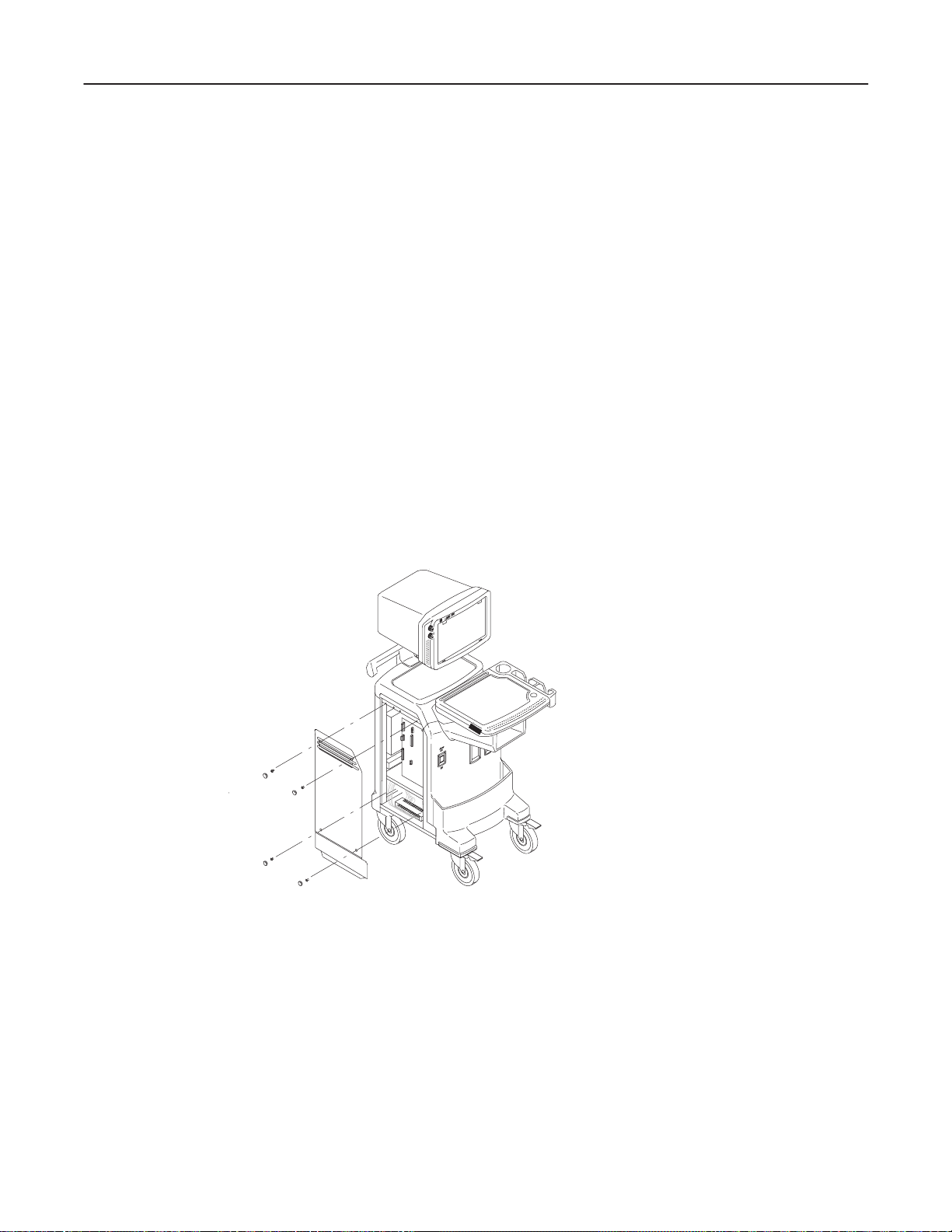
6–2–21 Shield Panel (FRU No. 307) 6–52. . . . . . . . . . . . . . . . . . . . . . . . . . . . . . . . . . . . . . . . . . . . . . . . . .
6–2–22 Mother Assy (FRU No. 308) 6–54. . . . . . . . . . . . . . . . . . . . . . . . . . . . . . . . . . . . . . . . . . . . . . . . . .
6–2–23 Nest Box (FRU No. 309) 6–56. . . . . . . . . . . . . . . . . . . . . . . . . . . . . . . . . . . . . . . . . . . . . . . . . . . . .
6–2–24 Swing Arm Assy (FRU No. 401) 6–58. . . . . . . . . . . . . . . . . . . . . . . . . . . . . . . . . . . . . . . . . . . . . . .
6–2–25 Pipe Assy (FRU No. 402) 6–60. . . . . . . . . . . . . . . . . . . . . . . . . . . . . . . . . . . . . . . . . . . . . . . . . . . .
6–2–26 Pole Cover (FRU No. 403) 6–62. . . . . . . . . . . . . . . . . . . . . . . . . . . . . . . . . . . . . . . . . . . . . . . . . . .
6–2–27 Left Cover (FRU No. 404) 6–64. . . . . . . . . . . . . . . . . . . . . . . . . . . . . . . . . . . . . . . . . . . . . . . . . . . .
6–2–28 Right Cover (FRU No. 405) 6–65. . . . . . . . . . . . . . . . . . . . . . . . . . . . . . . . . . . . . . . . . . . . . . . . . . .
6–2–29 Front Base Cover (FRU No. 406) 6–66. . . . . . . . . . . . . . . . . . . . . . . . . . . . . . . . . . . . . . . . . . . . .
6–2–30 Front Cover (FRU No. 407) 6–68. . . . . . . . . . . . . . . . . . . . . . . . . . . . . . . . . . . . . . . . . . . . . . . . . . .
6–2–31 Rear Cover (FRU No. 408) 6–70. . . . . . . . . . . . . . . . . . . . . . . . . . . . . . . . . . . . . . . . . . . . . . . . . . .
6–2–32 Top Cover (FRU No. 409) 6–72. . . . . . . . . . . . . . . . . . . . . . . . . . . . . . . . . . . . . . . . . . . . . . . . . . . .
6–2–33 Printer Cover (FRU No. 410) 6–74. . . . . . . . . . . . . . . . . . . . . . . . . . . . . . . . . . . . . . . . . . . . . . . . .
6–2–34 Printer Bracket Assy(FRU No. 411), Back Bracket Assy (FRU No. 412) 6–76. . . . . . . . . . . .
6–2–35 Rear Handle (FRU No. 413) 6–78. . . . . . . . . . . . . . . . . . . . . . . . . . . . . . . . . . . . . . . . . . . . . . . . . .
6–2–36 Neck Frame (FRU No. 414) 6–80. . . . . . . . . . . . . . . . . . . . . . . . . . . . . . . . . . . . . . . . . . . . . . . . . .
6–2–37 Rear Panel Assy (FRU No. 415) 6–82. . . . . . . . . . . . . . . . . . . . . . . . . . . . . . . . . . . . . . . . . . . . . .
6–2–38 Power S/W Assy (FRU No. 416) 6–84. . . . . . . . . . . . . . . . . . . . . . . . . . . . . . . . . . . . . . . . . . . . . .
6–2–39 AC Fan Assy (FRU No. 417) 6–86. . . . . . . . . . . . . . . . . . . . . . . . . . . . . . . . . . . . . . . . . . . . . . . . . .
6–2–40 Front Caster (FRU No. 418) 6–88. . . . . . . . . . . . . . . . . . . . . . . . . . . . . . . . . . . . . . . . . . . . . . . . . .
6–2–41 Rear Caster (FRU No. 419) 6–89. . . . . . . . . . . . . . . . . . . . . . . . . . . . . . . . . . . . . . . . . . . . . . . . . .
6–2–42 Bumper Set (FRU No. 420) 6–90. . . . . . . . . . . . . . . . . . . . . . . . . . . . . . . . . . . . . . . . . . . . . . . . . . .
6–2–43 EMI Cover L (FRU No. 421) 6–91. . . . . . . . . . . . . . . . . . . . . . . . . . . . . . . . . . . . . . . . . . . . . . . . . .
6–2–44 PCB Guide Assy (FRU No. 422) 6–92. . . . . . . . . . . . . . . . . . . . . . . . . . . . . . . . . . . . . . . . . . . . . .
6–2–45 Terminal Block 12 Assy (FRU No. 501) 6–94. . . . . . . . . . . . . . . . . . . . . . . . . . . . . . . . . . . . . . . . .
6–2–46 Terminal Block 6 Assy (FRU No. 502) 6–96. . . . . . . . . . . . . . . . . . . . . . . . . . . . . . . . . . . . . . . . . .
6–2–47 SMPS Assy (FRU No. 503) 6–98. . . . . . . . . . . . . . . . . . . . . . . . . . . . . . . . . . . . . . . . . . . . . . . . . . .
6–2–48 Power Trans Assy (FRU No. 504) 6–100. . . . . . . . . . . . . . . . . . . . . . . . . . . . . . . . . . . . . . . . . . . . .
6–2–49 Circuit Breaker Set (FRU No. 505) 6–102. . . . . . . . . . . . . . . . . . . . . . . . . . . . . . . . . . . . . . . . . . . .
6–3 FUSE REPLACEMENT 6–103. . . . . . . . . . . . . . . . . . . . . . . . . . . . . . . . . . . . . . . . . . . . . . . . . . . . . . . . . . . . . . .
6–3–1 Introduction 6–103. . . . . . . . . . . . . . . . . . . . . . . . . . . . . . . . . . . . . . . . . . . . . . . . . . . . . . . . . . . . . . . .
6–3–2 Replacement Procedures 6–103. . . . . . . . . . . . . . . . . . . . . . . . . . . . . . . . . . . . . . . . . . . . . . . . . . . .
6–4 SMPS Assy REPLACEMENT 6–106. . . . . . . . . . . . . . . . . . . . . . . . . . . . . . . . . . . . . . . . . . . . . . . . . . . . . . . . .
6–4–1 Introduction 6–106. . . . . . . . . . . . . . . . . . . . . . . . . . . . . . . . . . . . . . . . . . . . . . . . . . . . . . . . . . . . . . . .
6–4–2 Replacement Procedure 6–106. . . . . . . . . . . . . . . . . . . . . . . . . . . . . . . . . . . . . . . . . . . . . . . . . . . . .
iv
T ABLE OF CONTENTS
Page 15

GE MEDICAL SYSTEMS
REV 5
SECTION TITLE PAGE
LOGIQ α200 SERVICE MANUAL
2138853
CHAPTER 7 – PERIODIC MAINTENANCE
7–1 INTRODUCTION 7–3. . . . . . . . . . . . . . . . . . . . . . . . . . . . . . . . . . . . . . . . . . . . . . . . . . . . . . . . . . . . . . . . . . . .
7–1–1 Periodic Maintenance 7–3. . . . . . . . . . . . . . . . . . . . . . . . . . . . . . . . . . . . . . . . . . . . . . . . . . . . . . . .
7–2 PERIODIC MAINTENANCE PROCEDURE 7–3. . . . . . . . . . . . . . . . . . . . . . . . . . . . . . . . . . . . . . . . . . . . .
7–2–1 Visual Inspection 7–3. . . . . . . . . . . . . . . . . . . . . . . . . . . . . . . . . . . . . . . . . . . . . . . . . . . . . . . . . . . .
7–2–2 Cleaning 7–4. . . . . . . . . . . . . . . . . . . . . . . . . . . . . . . . . . . . . . . . . . . . . . . . . . . . . . . . . . . . . . . . . . .
7–2–3 Measurement 7–4. . . . . . . . . . . . . . . . . . . . . . . . . . . . . . . . . . . . . . . . . . . . . . . . . . . . . . . . . . . . . . .
7–2–4 Battery replacement 7–4. . . . . . . . . . . . . . . . . . . . . . . . . . . . . . . . . . . . . . . . . . . . . . . . . . . . . . . . .
7–2–5 Note 7–4. . . . . . . . . . . . . . . . . . . . . . . . . . . . . . . . . . . . . . . . . . . . . . . . . . . . . . . . . . . . . . . . . . . . . . .
7–3 ELECTRICAL SAFETY TESTS 7–5. . . . . . . . . . . . . . . . . . . . . . . . . . . . . . . . . . . . . . . . . . . . . . . . . . . . . . . .
7–3–1 Outlet Test Wiring Arrangement 7–5. . . . . . . . . . . . . . . . . . . . . . . . . . . . . . . . . . . . . . . . . . . . . . .
7–3–2 Grounding Continuity 7–6. . . . . . . . . . . . . . . . . . . . . . . . . . . . . . . . . . . . . . . . . . . . . . . . . . . . . . . .
7–3–3 Chassis Leakage Current Test 7–7. . . . . . . . . . . . . . . . . . . . . . . . . . . . . . . . . . . . . . . . . . . . . . . .
7–3–4 Probe Leakage Current Test 7–10. . . . . . . . . . . . . . . . . . . . . . . . . . . . . . . . . . . . . . . . . . . . . . . . . .
7–3–5 When There’s Too Much Leakage Current... 7–14. . . . . . . . . . . . . . . . . . . . . . . . . . . . . . . . . . . .
CHAPTER 8 – INSTALLATION FOR OPTIONS
8–1 INTRODUCTION 8–3. . . . . . . . . . . . . . . . . . . . . . . . . . . . . . . . . . . . . . . . . . . . . . . . . . . . . . . . . . . . . . . . . . . .
v
T ABLE OF CONTENTS
Page 16

GE MEDICAL SYSTEMS
REV 0
1–1 SERVICE MANUAL CONTENTS
This manual provides service information on the LOGIQ α200 Ultrasound Scanning System. It contains the
following chapters:
1. Chapter 1, Introduction: Contains a content summary and warnings.
2. Chapter 2, Installation: Contains physical and electrical requirements that must be considered prior to
installation and a complete LOGIQ α200 installation procedure with installation checklist.
3. Chapter 3, System Configuration: Contains system configuration and specifications.
4. Chapter 4, Functional Checks: Contains functional checks that must be performed as part of the
installation, or as required during servicing and periodic maintenance.
5. Chapter 5, Diagrams: Contains block diagrams and functional explanations of the LOGIQ α200 electronics.
6. Chapter 6, Renewal Parts: Contains a complete list of replacement parts for the LOGIQ α200 and
disassembly procedures for all changeable FRU.
7. Chapter 7, Periodic Maintenance: Provides periodic maintenance procedures for the LOGIQ α200.
LOGIQ α200 SERVICE MANUAL
2138853
8. Chapter 8, Installation for Options: is provided to keep the option installation instructions supplied with
each option.
1–3
INTRODUCTION
Page 17

GE MEDICAL SYSTEMS
REV 0
LOGIQ α200 SERVICE MANUAL
2138853
1–2 SAFETY
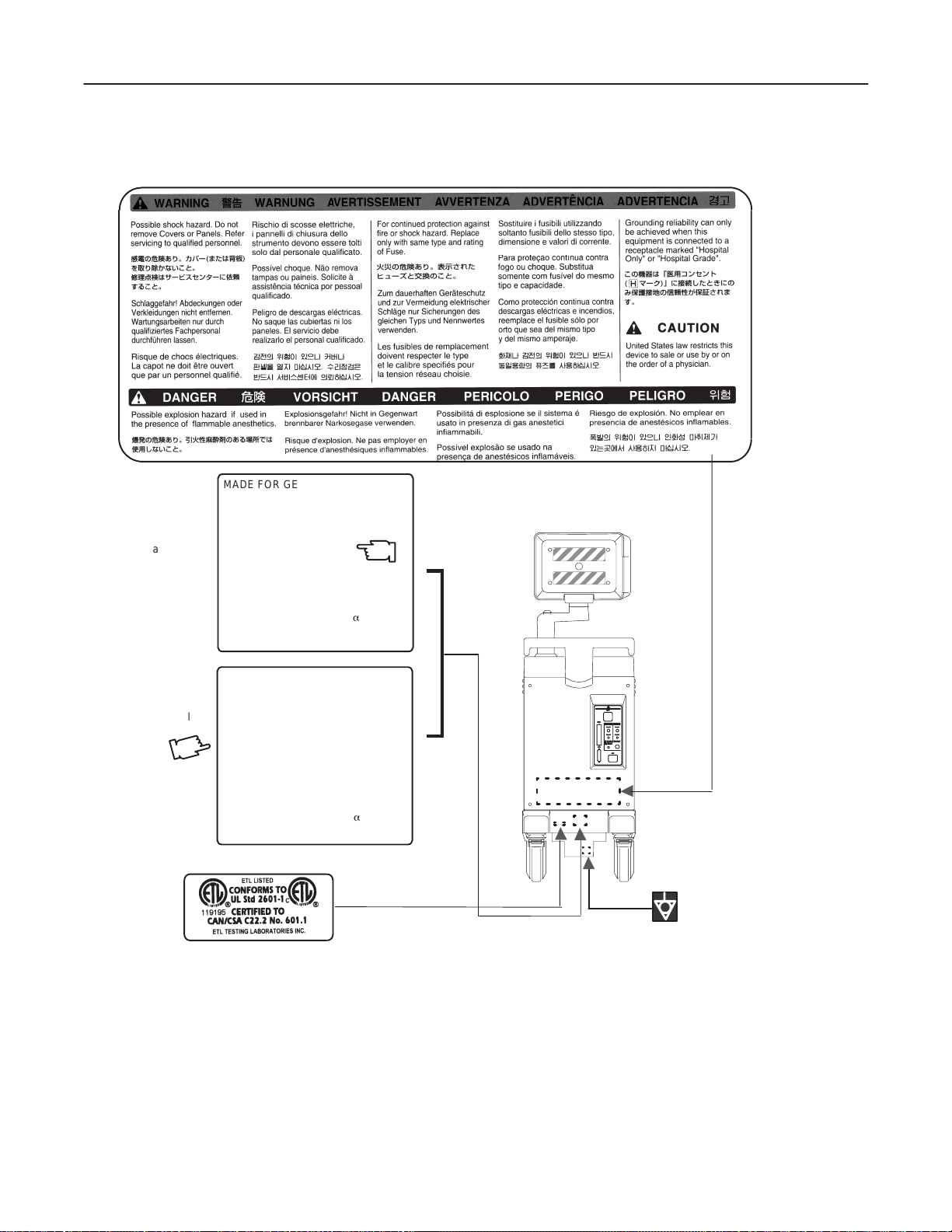
1–2–1 Warnings
W ARNING!
CAREFULLY READ ALL THE WARNINGS LISTED BELOW!
1. The operator manual should be fully read and understood before operating the LOGIQ α200 and kept nearby
for quick reference.
2. Although the ultrasound energy transmitted from the LOGIQ α200 transducer is within AIUM/NEMA
standards, unnecessary exposure should be avoided. Only trained personnel should operate the LOGIQ
α200.
3. To prevent electrical shock, the LOGIQ
α200 should be connected to a properly grounded power receptacle.
Do not use a three to two prong adapter. This defeats safety grounding.
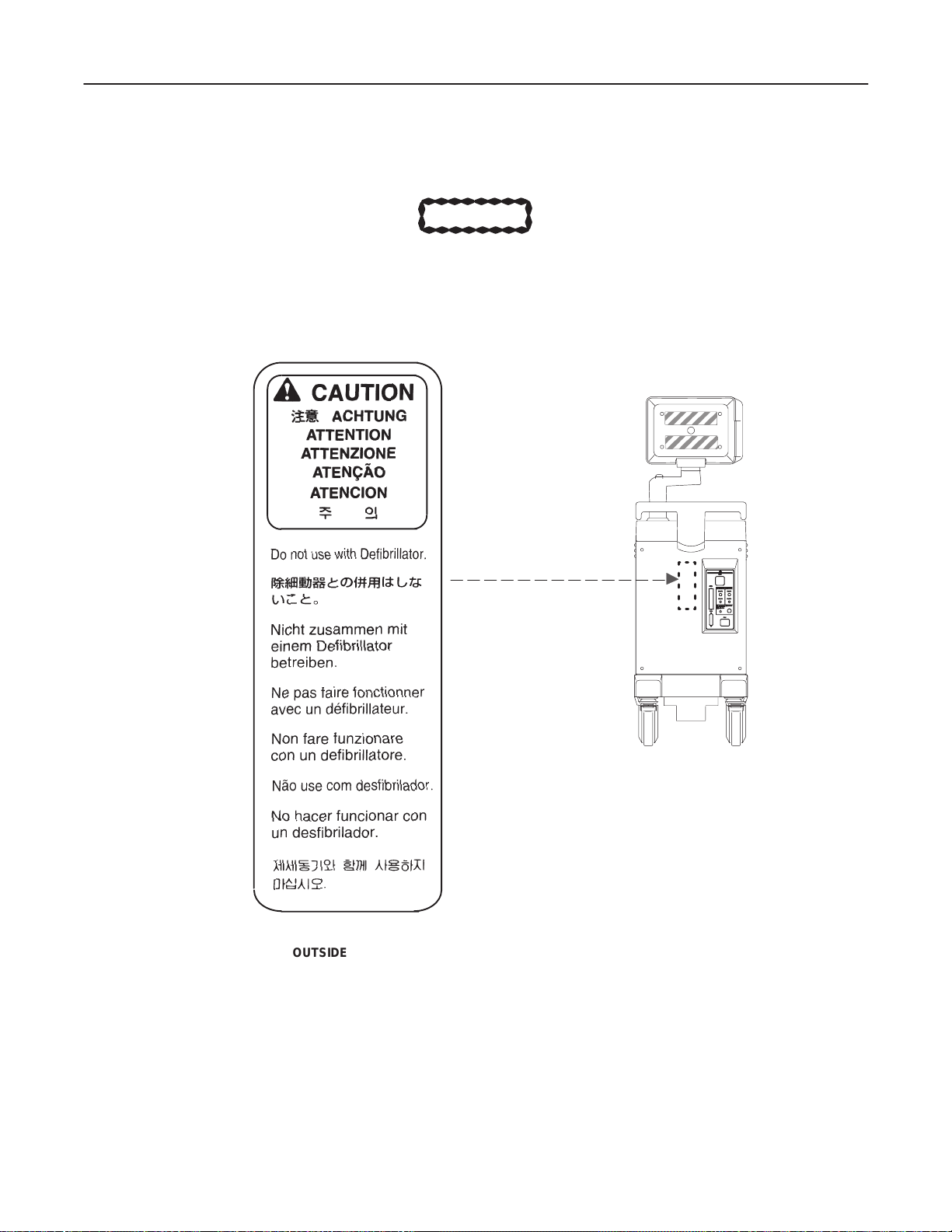
4. Do not use with Defibrillator when LOGIQ α200 is being operated .
5. Probes are fragile, please handle with care.
6. Concerning Outside Markings, refer to Illustration 1–1, 1–2, 1–3, 1–4, 1–5, 1–6, 1–7, 1–8, and 1–9.
7. For the cleaning, disinfection, and sterilization, refer to Probe section in LOGIQ
α200 User Manual and
Caution Sheet supplied with each probe.
NOTICE
This medical equipment is approved, in terms of the prevention of radio wave interference, to be
used in hospitals, clinics and other institutions which are environmentally qualified. The use of
this equipment in an inappropriate environment may cause some electronic interference to radios
and televisions around the equipment. Proper handling of this equipment is required in order to
avoid such trouble according to the operator and service manuals.
This equipment can be used in residential areas only under the supervision of physicians or
qualified technicians.
1–4
INTRODUCTION
Page 18
GE MEDICAL SYSTEMS
REV 0
1–2–1 Warnings (Continued)
LOGIQ α200 SERVICE MANUAL
2138853
OUTSIDE MARKINGS OF LOGIQ α200 (FOR ALL UNITS)
ILLUSTRATION 1–1
1–5
INTRODUCTION
Page 19
GE MEDICAL SYSTEMS
REV 0
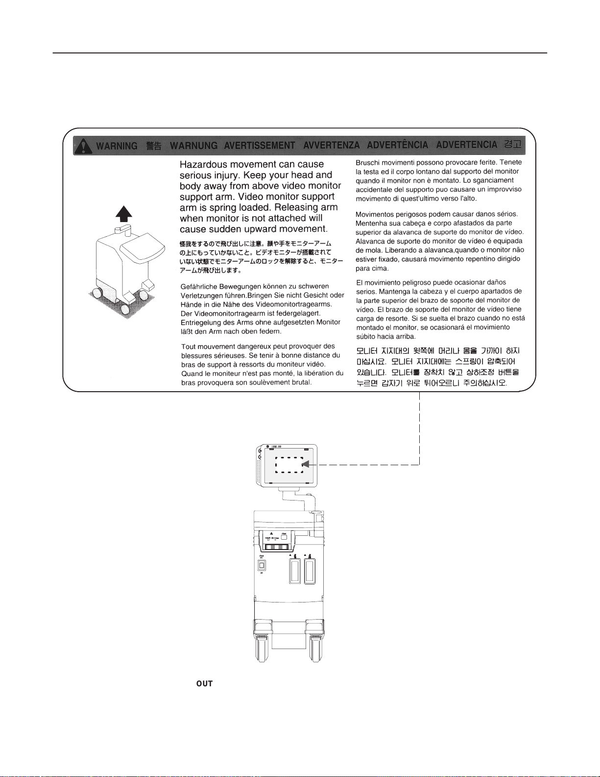
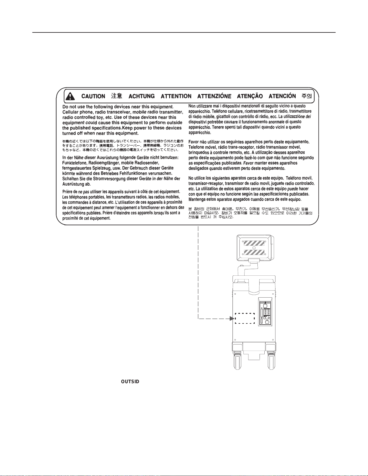
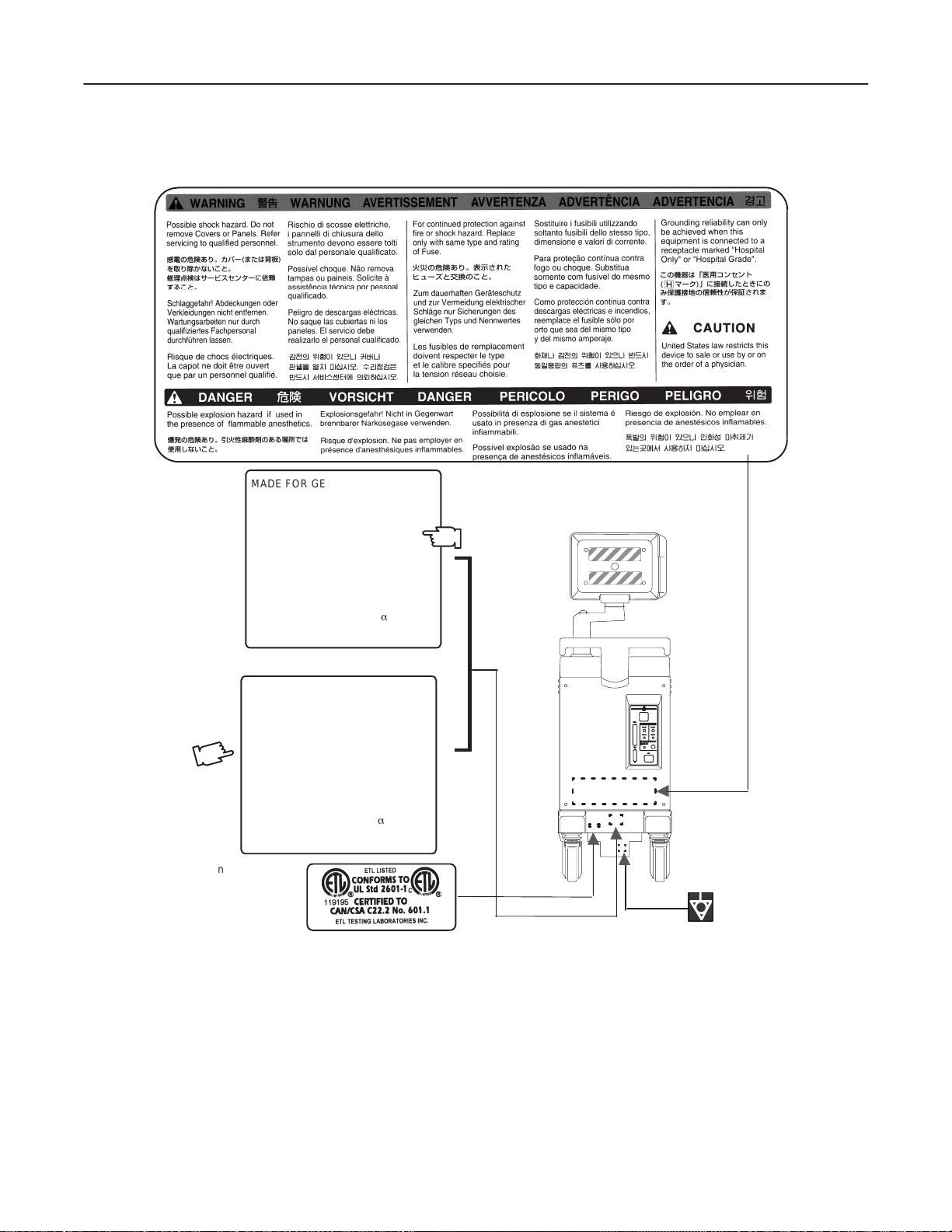
1–2–1 Warnings (Continued)
LOGIQ α200 SERVICE MANUAL
2138853
OUTSIDE MARKINGS OFLOGIQ α200 (FOR ALL UNITS)
ILLUSTRATION 1–2
Note
For further details regarding the cautions above, refer to 2–2–8 MOVING INTO POSITION in
Chapter 2.
1–6
INTRODUCTION
Page 20
GE MEDICAL SYSTEMS
REV 0
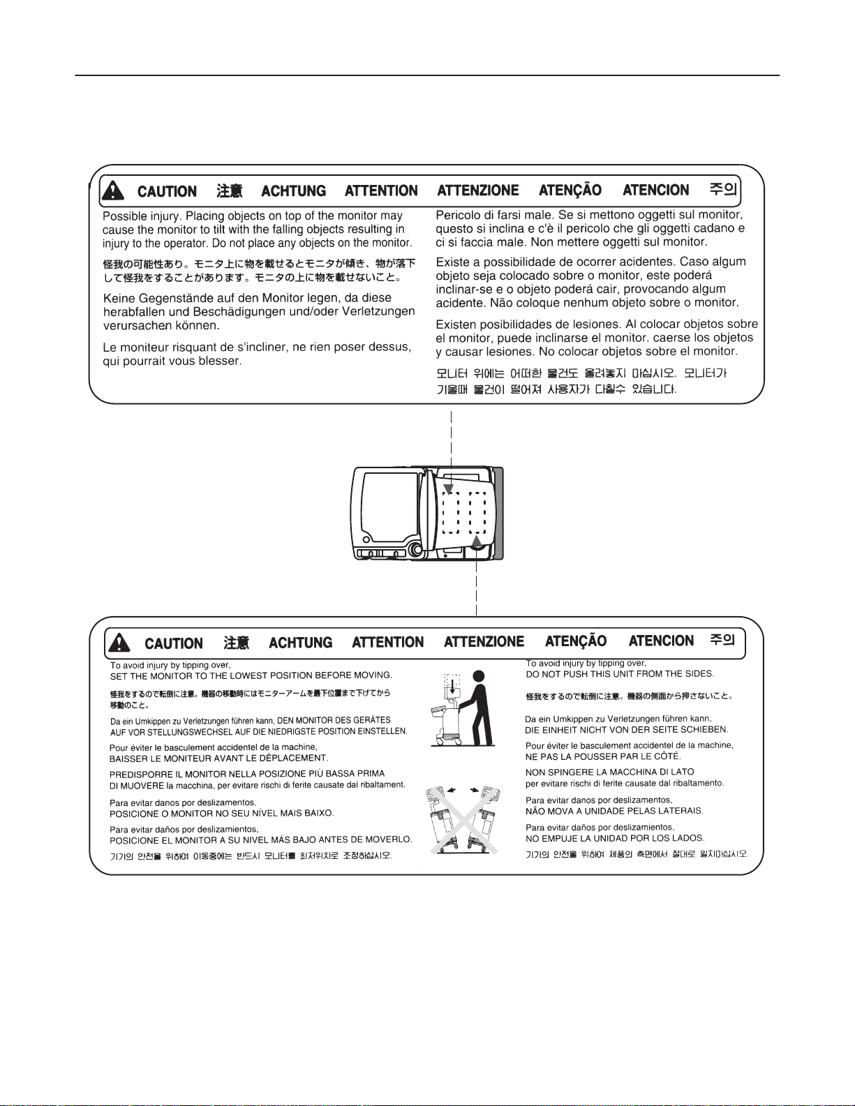
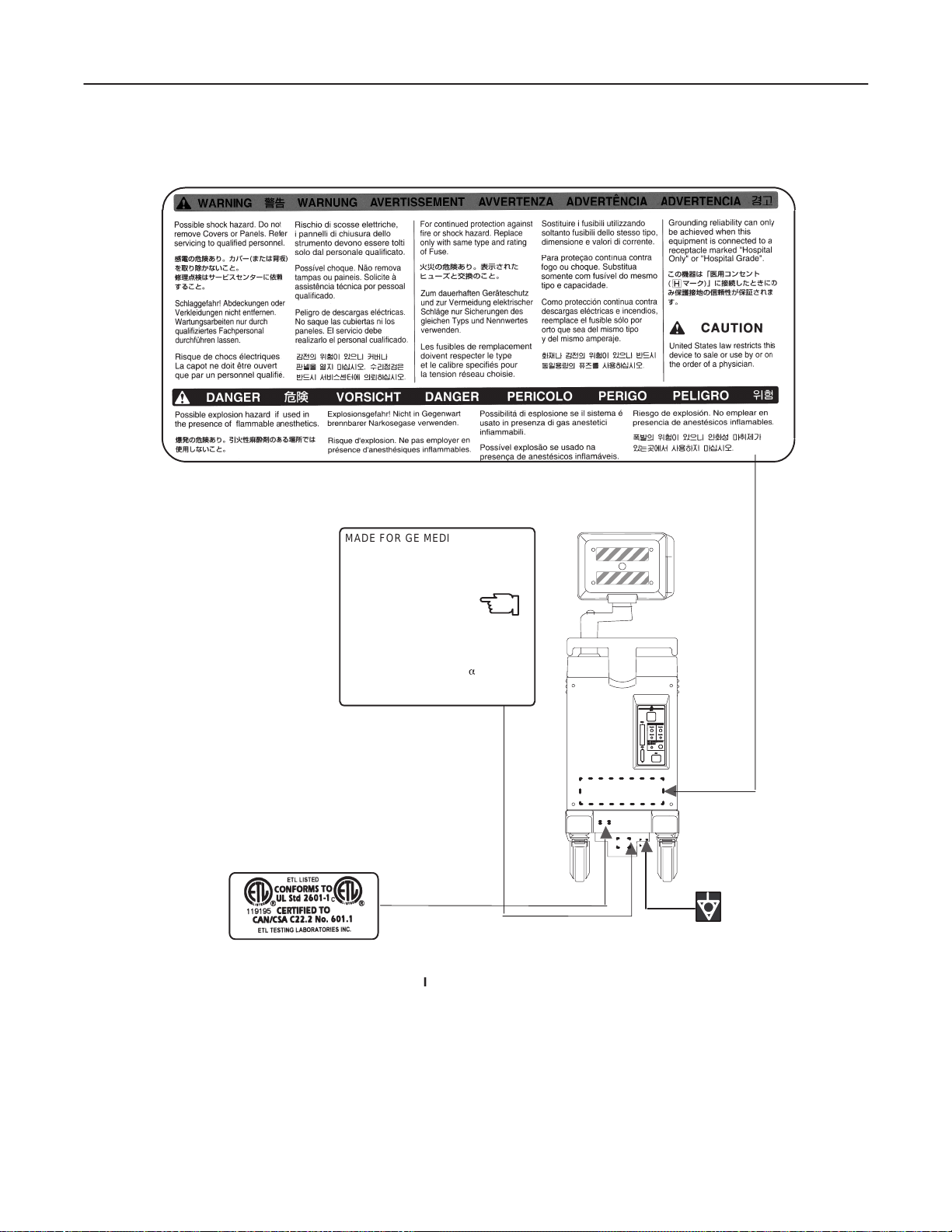
1–2–1 Warnings (Continued)
LOGIQ α200 SERVICE MANUAL
2138853
OUTSIDE MARKINGS OFLOGIQ α200 (FOR ALL UNITS)
ILLUSTRATION 1–3
1–7
INTRODUCTION
Page 21
GE MEDICAL SYSTEMS
REV 3
1–2–1 Warnings (Continued)
LOGIQ α200 SERVICE MANUAL
2138853
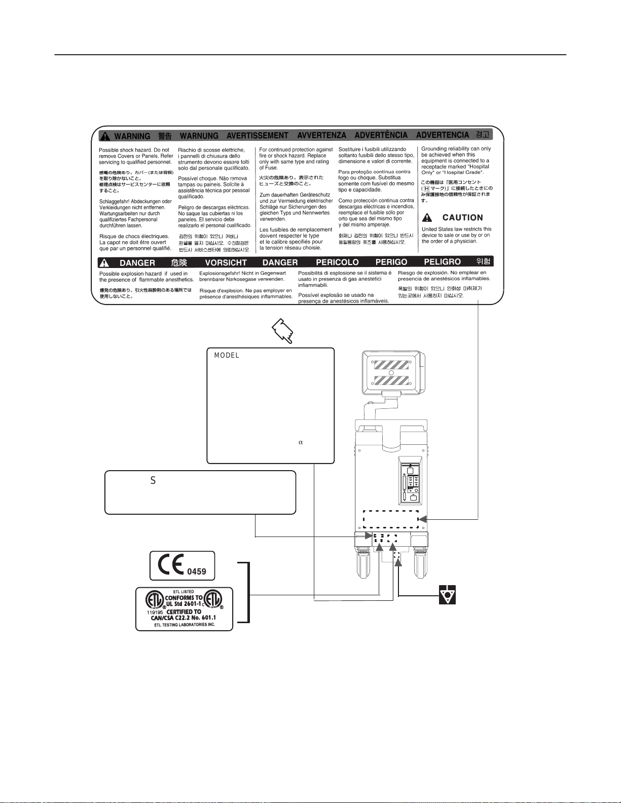
MODEL NUMBER : 2205674
MANUFACTURED
LOCATION:SAMSUNG GE MEDICAL
S.N. :
VOLT : 220–240V~
AMP. LONG TERM : 2.1A
KVA : 0.5kVA
PHASE : 1
DESC. : LOGIQa 200
CISPR 11 / EN 55011
CLASS : A GROUP : 1
CLASSE : A GROUPE : 1
Class1/Classe1
SYSTEMS
KOREA
OUTSIDE MARKINGS OFLOGIQ α200 (FOR EUROPE )
ILLUSTRATION 1–4
Note
For the symbols shown in the illustration above, refer to latter pages in this chapter.
1–8
INTRODUCTION
Page 22
GE MEDICAL SYSTEMS
REV 3
1–2–1 Warnings (Continued)
MADE FOR GE MEDICAL SYSTEMS
MILWAKEE, WISCONSIN BY
For USA
Canada,
Mexico
SAMSUNG G E MEDICAL SYSTEMS
MODEL 2205675
SERIAL.
MANUFACTURED
VOLTS : 120Vac~ 1 PHASE
POWER : 500VA
FREQUENCY : 60HZ
DESC, LOGIQa 200
KOREA
LOGIQ α200 SERVICE MANUAL
2138853
CLASS 1
For Brazil
MADE FOR GE ME DICAL SYSTEMS
MILWAKEE, WISCONSIN BY
SAMSUNG G E MEDICAL SYSTEMS
MODEL 2205676
SERIAL.
MANUFACTURED
VOLTS 220Vac~240Vac 1 PHASE
POWER : 500VA
FREQUENCY : 50HZ
DESC, LOGIQa 200
KOREA
CLASS 1
OUTSIDE MARKINGS OFLOGIQ α200 (FOR USA CANADA MAXICO BRAZIL)
ILLUSTRATION 1–5
1–9
INTRODUCTION
Page 23
GE MEDICAL SYSTEMS
REV 3
1–2–1 Warnings (Continued)
MADE FOR GE MEDICAL SYSTEMS
MILWAKEE, WISCONSIN BY
SAMSUNG G E MEDICAL SYSTEMS
MODEL 2205672
SERIAL.
MANUFACTURED
VOLTS :220Vac~240V ac 1 PHASE
POWER : 500VA
FREQUENCY : 50HZ
DESC, LOGIQa 200
KOREA
LOGIQ α200 SERVICE MANUAL
2138853
CLASS 1
For SEA, China, Hongkong, India, Australia, New Zealand
MADE FOR GE ME DICAL SYSTEMS
MILWAKEE, WISCONSIN BY
SAMSUNG G E MEDICAL SYSTEMS
MODEL 2205671
SERIAL.
MANUFACTURED
VOLTS : 120Vac~ 1 PHASE
POWER : 500VA
FREQUENCY : 60HZ
DESC, LOGIQa 200
For Taiwan Philippines
KOREA
CLASS 1
OUTSIDE MARKINGS OFLOGIQ α200 (FOR SEA CHINA HONGKONG INDIA AUSTRALLIA NEWZEALAND TAIWAN PHILLIPPINES)
ILLUSTRATION 1–6
1–10
INTRODUCTION
Page 24
GE MEDICAL SYSTEMS
REV 3
1–2–1 Warnings (Continued)
LOGIQ α200 SERVICE MANUAL
2138853
MADE FOR GE MEDICAL SYSTEMS
MILWAKEE, WISCONSIN BY
SAMSUNG G E MEDICAL SYSTEMS
MODEL 2205677
SERIAL. :
MANUFACTURED
VOLTS : 220–240Vac~ 1 PHASE
POWER : 500VA
FREQUENCY : 60HZ
DESC LOGIQa 200
OUTSIDE MARKINGS OFLOGIQ α200 (FOR CHILE)
KOREA
CLASS 1
ILLUSTRATION 1–7
1–1 1
INTRODUCTION
Page 25
GE MEDICAL SYSTEMS
REV 0
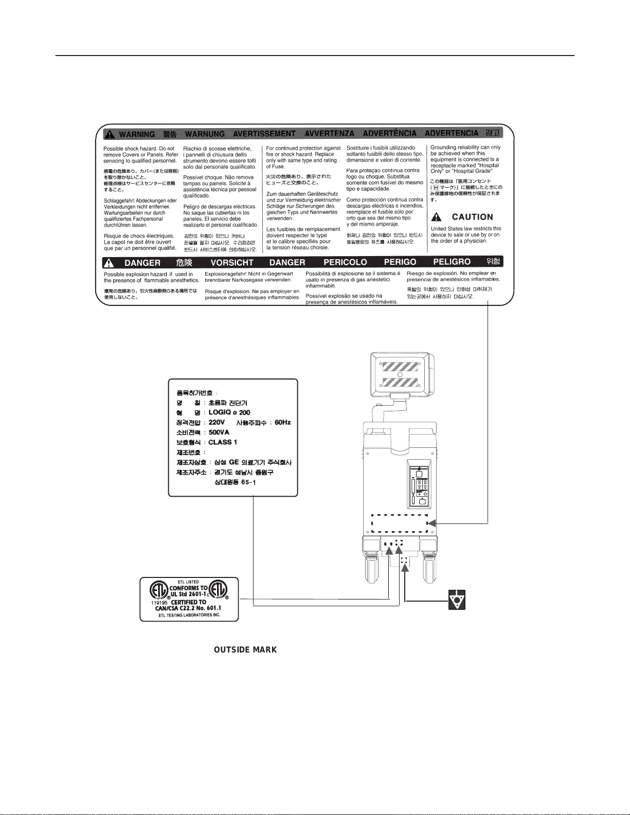
1–2–1 Warnings (Continued)
LOGIQ α200 SERVICE MANUAL
2138853
OUTSIDE MARKINGS OFLOGIQ α200 (FOR KOREA)
ILLUSTRATION 1–8
1–12
INTRODUCTION
Page 26
GE MEDICAL SYSTEMS
REV 0
1–2–1 Warnings (Continued)
Do not use a Defibrillator simultaneously with the ECG, as its excessive voltage will
damage the signal input block of the ECG unit.
LOGIQ α200 SERVICE MANUAL
2138853
CAUTION
OUTSIDE MARKINGS OF LOGIQ α200 (FOR UNITS WITH ECG)
ILLUSTRATION 1–9
1–13
INTRODUCTION
Page 27
GE MEDICAL SYSTEMS
REV 0
1–2–1 Warnings (Continued)
LOGIQ α200 SERVICE MANUAL
2138853
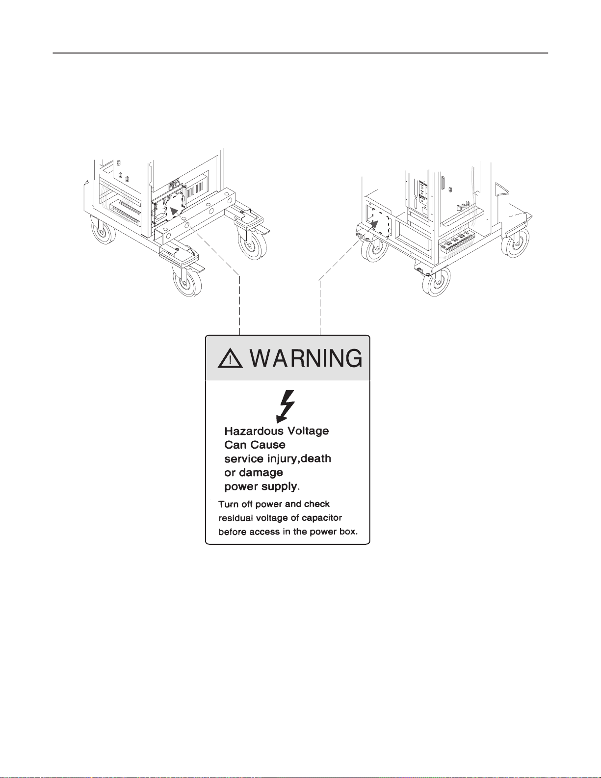
NOTE: Two labels are attached on rear of the SMPS assy box inside the rear cover
and front of HV Board Assy inside the front base cover.
MARKINGS OF LOGIQ 500 (INSIDE COVERS)
ILLUSTRATION 1–10
1–14
INTRODUCTION
Page 28
GE MEDICAL SYSTEMS
REV 0
LOGIQ α200 SERVICE MANUAL
2138853
1–2–1 Warnings (Continued)
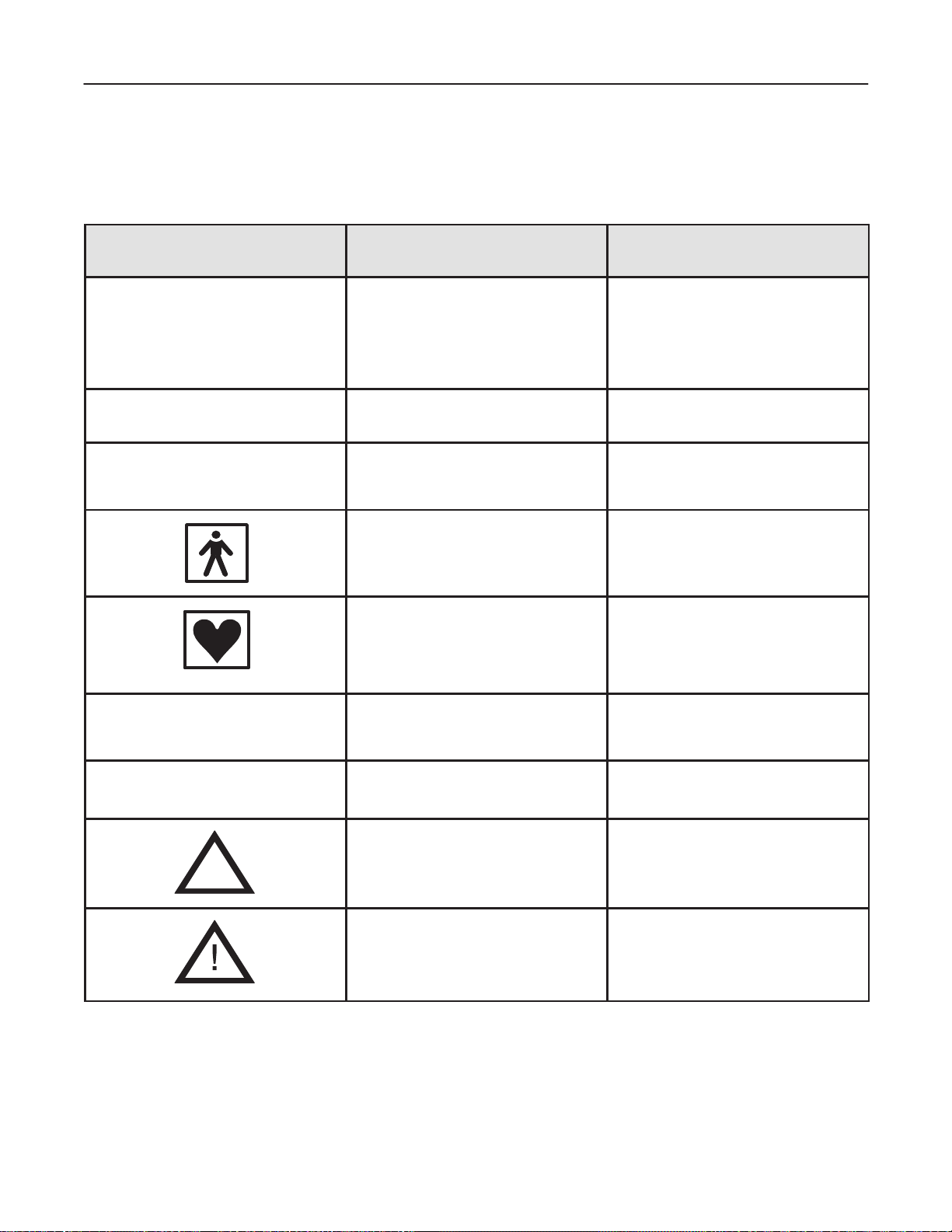
The following table describes the purpose and location of safety labels and other important information provided
on the equipment.
Label/Icon Purpose/Meaning Location
Identification and Rating Plate
Type/Class Label
IP Code
(IPX1)
Device Listing/
Certification Labels
Manufacturer’s name and address
Date of manufacture
Model and serial numbers
Electrical ratings (Volts, Amps, phase, and
frequency)
Used to indicate the degree of safety or protection.
Indicates the degree of protection provided
by the enclosure per IEC 529. IPX1
indicates drip proof.
Equipment Type BF (man in the box symbol)
IEC 878-02-03 indicates B Type equipment
having a floating applied part.
Equipment Type CF (heart in the box
symbol) IEC 878-02-05 indicate equipment
having a floating applied part having a
degree of protection suitable for direct
cardiac contact.
Laboratory logo or labels denoting
conformance with industry safety standards
such as UL or IEC.
Rear of console near power inlet
Foot Switch
Probe connectors
ECG connector and surgical probes
Rear of console
“DANGER – Risk of explosion used
in...”
The system is not designed for use with
flammable anesthetic gases.
“CAUTION” The equilateral triangle is usually
used in combination with other symbols to
advise or warn the user.
“ATTENTION – Consult accompanying
documents” is intended to alert the user to
refer to the operator manual or other
instructions when complete information
cannot be provided on the label.
1–15
Rear of console
Various
V arious
INTRODUCTION
Page 29
GE MEDICAL SYSTEMS
REV 0
1–2–1 Warnings (Continued)
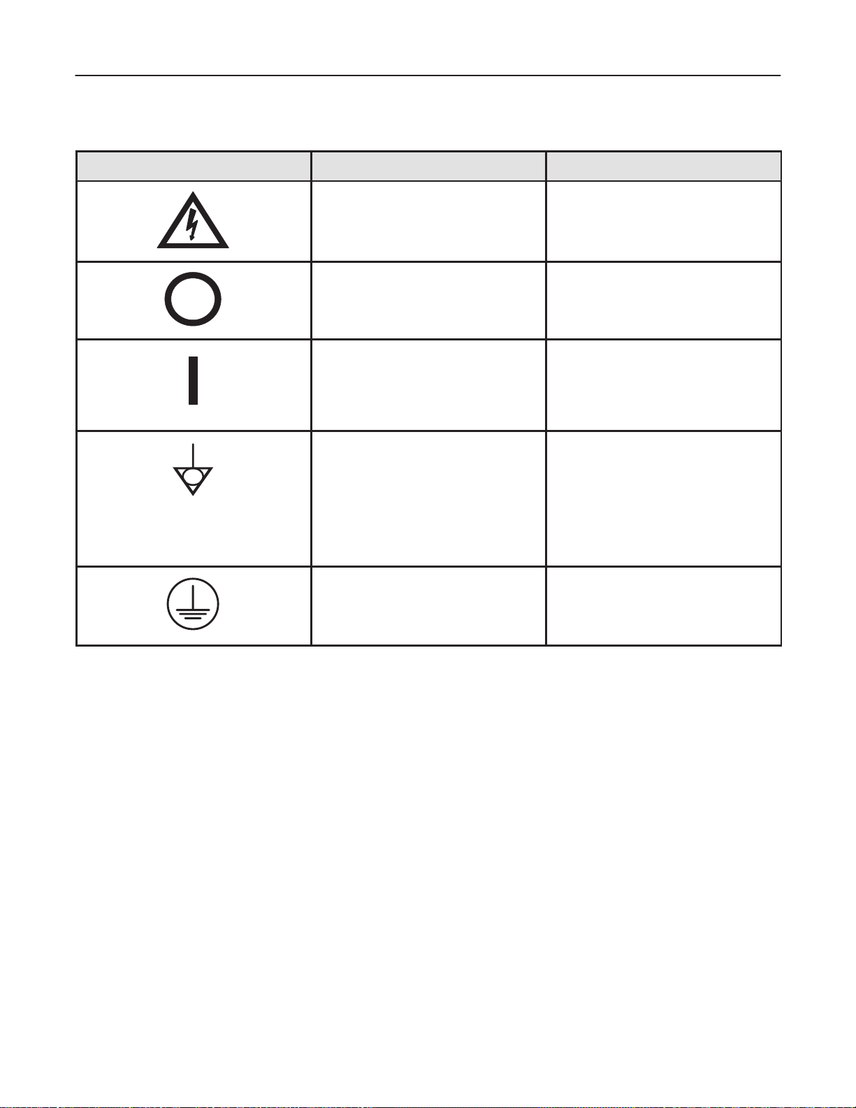
Label/Icon Purpose/Meaning Location
LOGIQ α200 SERVICE MANUAL
2138853
“CAUTION – Dangerous voltage” (the
lightning flash with arrowhead in equilateral
triangle) is used to indicate electric shock
hazards.
“Mains OFF” Indicates the power off position
of the mains power switch.
“Mains ON” Indicates the power on position
of the mains power switch.
“Equipotentiality” Indicates the terminal to be
used for connecting equipotential conductors
when interconnecting (grounding) with other
equipment.
CAUTION
This is only for ”FUNCTIONAL
GROUNDING”, NOT ”PROTECTIVE
EARTH”.
Indicates Main protective earth
terminal
Various
Front of system,
Main power switch
Front of system,
Main power switch
Rear of console
Various
1–16
INTRODUCTION
Page 30

GE MEDICAL SYSTEMS
REV 3
1–2–2 Specifications
Type of protection against electric shock: Class I EQUIPMENT (*1)
Degree of protection against electric shock: Type BF EQUIPMENT (*2) (Except ECG)
Type CF EQUIPMENT (*3) (ECG Only)
Ordinary Equipment
Continuous Operation
*1. Class I EQUIPMENT
EQUIPMENT in which protection against electric shock does not rely on BASIC INSULATION only, but
which includes an additional safety precaution in that means are provided for the connection of the
EQUIPMENT to the protective earth conductor in the fixed wiring of the installation in such a way that
ACCESSIBLE METAL PARTS cannot become LIVE in the event of a failure of the BASIC INSULATION.
*2. Type BF EQUIPMENT
TYPE B EQUIPMENT with an F–TYPE APPLIED P ART
TYPE B EQUIPMENT: EQUIPMENT providing a particular degree of protection against electric shock,
particularly regarding:
LOGIQ α200 SERVICE MANUAL
2138853
– allowable LEAKAGE CURRENT;
Normal mode Single failure mode
Patient leakage current Less than 100µA Less than 500µA
*3. Type CF EQUIPMENT
EQUIPMENT providing a particular degree of protection higher than that for TYPE OF BF EQUIPMENT
against electronic shock particularly regarding allowable LEAKAGE CURRENT, and having an F–TYPE
APPLIED P AR T.
– allowable LEAKAGE CURRENT;
Normal mode Single failure mode
Patient leakage current Less than 10µA Less than 50µA
1–17
INTRODUCTION
Page 31

GE MEDICAL SYSTEMS
REV 0
1–3 EMC (Electromagnetic Compatibility)
1–3–1 EMC Performance
All types of electronic equipment may characteristically cause electromagnetic interference with other equipment,
either through air or connecting cables. The term EMC (Electromagnetic Compatibility) indicates capability of the
equipment, which curbs electromagnetic influence from other equipment and at the same time does not affect
other equipment with similar electromagnetic radiation from itself.
This product is designated to fully comply with EN60601–1–2 (IEC 601–1–2), In Medical electronic equipment
EMC regulations.
Proper installation following this service manual is required in order to achieve the full EMC performance of the
product.
The product must be installed as stipulated in 1–3–2, Notice upon Installation of Product.
In case of issues related to EMC, please follow procedures stated in 1–3–4, Countermeasures against
EMC-related Issues.
LOGIQ α200 SERVICE MANUAL
2138853
1–3–2 Notice upon Installation of Product
1) Use either power supply cords provided or designated by GEMS or SGMS. Products equipped with
power source plug should be plugged into the fixed power socket which has the protective grounding
conductor.
Connect a three-pole plug to a three-pole socket without using a three-pole-to-two-pole converter.
2) Locate the equipment as far as possible from other electronic equipment.
3) Be sure to use cables provided by GEMS and SGMS. Wire these cables following these installation
procedures.
(Example) Wire power cables separately from signal cables.
4) Lay out the main equipment and other peripherals following the installation procedures described in
Chapter2, INST ALLATION.
1–18
INTRODUCTION
Page 32

GE MEDICAL SYSTEMS
REV 0
1–3–3 General Notice
1) Designation of Peripheral Equipment Connectable to This Product
Equipment which conforms to EN60601–1–2 (IEC601–1–2), can be hooked up to the product without
compromising its EMC performance.
Avoid using other equipment. Failure to comply with this instruction may result in poor EMC performance
of the product.
2) Notice against User Modification
Never modify this product. Unilateral user modification may cause degradation in EMC performance.
Modification of the product includes:
a) Changes in cables (length, material, wiring etc.)
b) Changes in system installation/layout
c) Changes in system configuration/components
LOGIQ α200 SERVICE MANUAL
2138853
d) Changes in means of fixing system/parts (cover open/close, screwing cover)
3) Operate the system with all covers closed. If you open any cover for some reason, be sure to close it
before starting/resuming operation.
Operating the system with any cover open may affect EMC performance.
1–3–4 Countermeasures against EMC-related Issues
Generally it is very difficult to handle issues related to EMC. It may be time consuming and costly.
General countermeasures
Electromagnetic interference with other equipment
1) Electromagnetic interference may be alleviated by positioning other equipment far from the system.
2) Electromagnetic interference may be mitigated by changing the relative location (installation angle)
between the system and other equipment.
3) Electromagnetic interference may be eased by changing wiring locations of power/signal cables of other
equipment.
4) Electromagnetic influence may be reduced by altering the path of power supply for other equipment.
1–3–5 Notice on Service
1) Ensure all screws are tight after servicing. Loose screws may cause degradation in EMC performance.
2) In case the high frequency gasket of this system is broken, replace it with a new one immediately.
1–19
INTRODUCTION
Page 33

GE MEDICAL SYSTEMS
REV 5
1–4 ADDRESS
This system is not repairable by the customer. If this equipment does not work as indicated in the Operator
Manual, please contact your service support center. If the service engineer needs additional information to repair
this equipment, please contact the following address (The necessary information will be provided to the Service
Engineer as needed):
GE Medical Systems
Ultrasound Business Group
4855 W. Electric Ave., Milwaukee, WI 53219
USA
TEL: (1) 800–437–1171
FAX: (1) 414–647–4090
CANADA
TEL: (1) 800–668–0732
LATIN & SOUTH AMERICA
TEL: (1) 305–735–2304
LOGIQ α200 SERVICE MANUAL
2138853
GE Ultrasound Europe
GE Ultraschall GmbH & Co.KG
Beethovenstrabe 239 Postfach 11 05 60
D–42655 Solingen GERMANY
TEL: 0130–81–6370 (OLC–Europe Toll Free Number)
(49) 212–2802–207 (English/German Hotline)
(49) 212–2802–208 (English/German/French Hotline)
FAX: (49) 212–2802–28
GE Yokogawa Medical Systems
On–Line Center (OLC), Asia
Ultrasound Group
67–4, Takakura–cho, Hachioji–shi, Tokyo, 192–0033
JAPAN
TEL: (81) 426–48–2940
FAX: (81) 426–48–2950
SAMSUNG GE MEDICAL SYSTEMS
64–3, Sangdaewon–dong, Chungwon–Ku,
Sungnam–Si, Kyunggi–do,
KOREA
TEL: (82) 342–40–6000
FAX: (82) 342–42–0420
1–20
INTRODUCTION
Page 34

GE MEDICAL SYSTEMS
REV 0
LOGIQ α200 SERVICE MANUAL
2138853
2–1 PREINSTALLATION
2–1–1 Introduction
This section describes various general electrical, operational, and environmental considerations that must be
considered before installing the LOGIQ
α200 Ultrasound unit.
2–1–2 Power Line Requirements
The following power line parameters should be monitored for one week before installation. We recommend that
you use an analyzer Dranetz Model 606–3 or Dranetz Model 626:
PARAMETER : LIMITS
Voltage Range : Korea : 220 VAC ± 10% (198 – 242 VAC)
: USA : 115 VAC ±10% (103 – 127 VAC)
: Europe, LA : 220 – 240 VAC 10%(198 –264 VAC)
: Japan. : 100 VAC ± 10% (90 – 110 VAC)
: Asia : 115 VAC ± 10% (103 – 127 VAC)
: 220 – 240 VAC 10%(198 –264 VAC)
Voltage Range : All applications : MAX. 500 VA
Line Frequency : All applications : 50/60Hz (±2Hz)
Power Transients : Less than 25 % of nominal peak voltage for less than 1 millisecond for any type of
transient, including line frequency, synchronous, asynchronous, or aperiodic
transients.
Decaying Oscillation : Less than 15 % of peak voltage for less than 1 millisecond.
2–3
INSTALLATION
Page 35

GE MEDICAL SYSTEMS
REV 2
LOGIQ α200 SERVICE MANUAL
2138853
2–1–3 Physical Specifications
The LOGIQ α200 (excluding accessories) weighs 76 Kg (168 lbs). See Chapter 3, ILLUSTRATION 3–1 for
dimensions.
Operating Conditions
The LOGIQ
α200 is designed to operate within a temperature range of 10
_
C to 40 _C (50 _F to 104 _F), and a
relative humidity range of 5 % to 90 % (Non–condensing).
Patient Comfort
Concerning permissible operating temperature and humidity tolerances, we recommend that ambient room
temperature should be maintained between 20 _C to 26 _C (68 _F to 79 _F), Humidity should be maintained
between 50 % and 70 % for patient comfort during ultrasound scanning.
Electromagnetic Interference (EMI)
Ultrasound machines are susceptible to interference from the radio frequencies, magnetic fields, and transients in
the air or power leads. Possible EMI sources should be identified. Electrical and electronic equipment may
produce EMI unintentionally or as a result of a malfunction. These sources include medical lasers, cauterizing
guns, computers, monitors, fans, gel warmers, microwave ovens, and cellular phones. The presence of
broadcast station or van may also cause interference.
Carefully read the following precautions before installing the unit.
1. Connect the power plug for any other equipment into the fixed outlet with ground wire.
2. Securely connect any equipment with permanent ground connection to the earth ground furnished in the
building.
3. Install the unit as far from any electrical or electronic equipment as possible.
If any EMI troubles are known or suspected to be present, try to deal with the equipment suspected to have
influence on the Ultrasound machine as follows:
1. Move the ultrasound machine as far from the equipment as possible.
2. Change the arrangement of the equipment in the room.
3. Plug the equipment into other outlet.
4. Move the power cable or signal cable connected with the equipment.
Securely re-tighten drive any screws for the Ultrasound machine after re-assembling for service operation.
2–4
INSTALLATION
Page 36

GE MEDICAL SYSTEMS
REV 0
2–1–4 Recommended Ultrasound Room Layout
TABLE 2– 1 provides the requirements for an ultrasound room:
TABLE 2– 1
ULTRASOUND ROOM REQUIREMENTS
POWER SOURCE 230VAC, 50Hz, SINGLE PHASE For Europe Version
115V, 60Hz, SINGLE PHASE For USA Version
CURRENT RATING 2A (115V, 100V) ; 1A (220–240V) CIRCUIT BREAKER
RADIATION SHIELDING NONE REQUIRED for ULTRASOUND ENERGY
TEMPERATURE 20–26 _C (68–79 _F) for PATIENT COMFORT
HUMIDITY 50% to 70% for PATIENT COMFORT
LOGIQ α200 SERVICE MANUAL
2138853
HEAT DISSIPA TION 2000 BTU/Hr for LOGIQ
FLOOR LOADING Approximately 240 – 300 kg/m
FLOOR CONDITION Gradient : WITHIN 5 degrees
α200 Weight 76 kg (168lbs) without Accessories
LOGIQ
α200
2
without Accessories
2–5
INSTALLATION
Page 37

GE MEDICAL SYSTEMS
REV 2
2–1–4 Recommended Ultrasound Room Layout (Continued)
Optional Desirable Ultrasound Room Facilities
These facilities are:
1. Lab sink with hot and cold water.
2. Emergency oxygen supply.
3. Dimmer control for overhead lights.
4. Film viewer.
5. Film and linen storage.
6. Medical equipment storage.
7. Hospital grade equipment electrical outlet.
8. Document storage area for operating and service manuals.
LOGIQ α200 SERVICE MANUAL
2138853
9. Nearby waiting room, dressing room, lavatory.
10. Trash bin.
Recommended and Alternate Ultrasound Console Floor Plans
ILLUSTRATION 2–1 provides a recommended standard floor plan and a minimal floor plan for ultrasound
equipment
2–6
INSTALLATION
Page 38

GE MEDICAL SYSTEMS
REV 0
2–1–4 Recommended Ultrasound Room Layout (Continued)
LOGIQ α200 SERVICE MANUAL
2138853
Film
Processing
Room
File
Cabinet
Desk
Film Viewer
Counter
Top
Dedicated power outlet
Linens
Probes/PM
Suction
Sink
Line
Emergency
Oxygen
LOGIQ
a
200
Stool
GE cabinet
for software
and manuals
193 cm
Examination Table
61 cm
Patient
Toilet
Facility
Scale: each square equals
one square foot
Film Viewer
Film Supplies
76 cm
30 in
An 8 by 10 Minimal Floor Plan
A 14 by 17 Recommended Floor Plan
Sink
Stool
Linens
Probes/supplies
LOGIQ
a
200
61 cm
Examination Table
193 cm
RECOMMENDED ULTRASOUND FLOOR PLAN
ILLUSTRATION 2–1
107 cm
42 in
Dedicated power outlet
GE cabinet
for software
and manuals
2–7
INSTALLATION
Page 39

GE MEDICAL SYSTEMS
LOGIQ α200 SERVICE MANUAL
REV 0
2–2 INSTALLATION
2–2–1 Introduction
This section contains many of the procedures required to install the LOGIQ α200 console.
2–2–2 Average Installation Time
2138853
The LOGIQ
approximately three hours. LOGIQ
α200 has been designed to be installed and checked out by an experienced service technician in
α200 consoles with optional equipment may take slightly longer.
2–2–3 Installation Warnings
1. Since the LOGIQ
α200 weighs approximately 76 kg (168 lbs) without options, preferably two people should
unpack it. Two people are also preferable for installing any additional bulky items.
2. There are no operator serviceable components. To prevent shock, do not remove any covers or panels.
Should problems or malfunctions occur, unplug the power cord. Only qualified service personnel should
carry out servicing and troubleshooting.
Note
For information regarding packing labels, refer to ILLUSTRATION 2–3, LABELS ON PACKAGE.
3. After being transported, the unit may be very cold or hot. If this is the case, allow the unit to acclimate before
you turn it on. It requires one hour for each 2.5°C increment if it’s temperature is below 10°C or above 40°C.
CAUTION
Equipment damage possibility. Turning the system on without acclimation after arriving at
site may cause the system to be damaged.
TABLE 2– 2
TIME FOR SETTLEMENT
°C 60 55 50 45 40 35 30 25 20 15 10 5 0 –5 –10 –15 –20 –25 –30 –35 –40
°F 140 131 122 113 104 95 86 77 68 59 50 41 32 23 14 5 –4 –13 –22 –31 –40
hrs 864200000002468101214161820
2–2–4 Checking the Components
When a new system arrives, check that any components are not damaged and or missing. If shipping damage or
shortages occur, contact the address shown in Chapter 1.
2–8
INSTALLATION
Page 40

GE MEDICAL SYSTEMS
REV 5
2–2–5 Unpacking LOGIQ α200
CAUTION
Do not lift the unit by the Keyboard or Monitor arm. Equipment damage may result.
CAUTION
The unit weighs approximately 76 kg (168 lbs). Be prepared for a sudden shift of weight as
the unit is removed from its base (pallet).
Refer to ILLUSTRATION 2–2 while performing the following procedure.
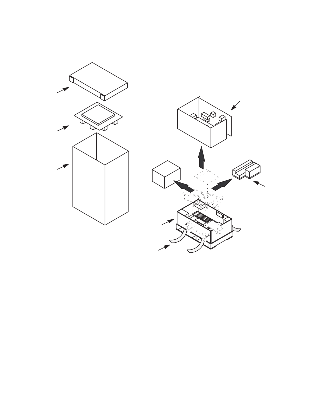
1. Cut the two BANDs.
LOGIQ α200 SERVICE MANUAL
2138853
2. Lift the CAP up and off.
3. Lift the TOP PAD up and off.
4. Remove the OPTION BOX.
5. Remove the VINYL COVER.
6. Remove the MIDDLE PLATE ASSY.
7. Remove the MONITOR COVER.
8. Lift the PACKING CASE up and off.
9. Lift the Monitor up by pressing the <UP/DOWN> button located on the Monitor Arm.
10. Remove the MONITOR PAD.
11. Return the Monitor arm to its lowest position.
12. Carefully roll the LOGIQ
13. Remove the Caution Label attached on the CRT Filter and clean the CRT Filter.
Check the shipping container for special instructions. Verify that the container is intact. In some
cases a secondary container may be used. If so, ask the carrier for unpacking instructions.
α200 from the PALLET.
Note
2–9
INSTALLATION
Page 41
GE MEDICAL SYSTEMS
REV 0
2–2–5 Unpacking LOGIQ α200 (Continued)
LOGIQ α200 SERVICE MANUAL
2138853
CAP
TOP PAD
PACKING
PLATE
OPTION BOX
PALLET
MIDDLE PLA TE
MONITOR PAD
BAND
UNPACKING LOGIQ α200
ILLUSTRATION 2–2
2–10
INSTALLATION
Page 42

GE MEDICAL SYSTEMS
REV 5
2–2–5 Unpacking LOGIQ α200 (Continued)
LOGIQ α200 SERVICE MANUAL
2138853
60dC
Air Pressure
700 -1060hPa
Humidity 30-95%
EXcluding Condensation
-10dC
LABELS ON PACKAGE
ILLUSTRATION 2–3
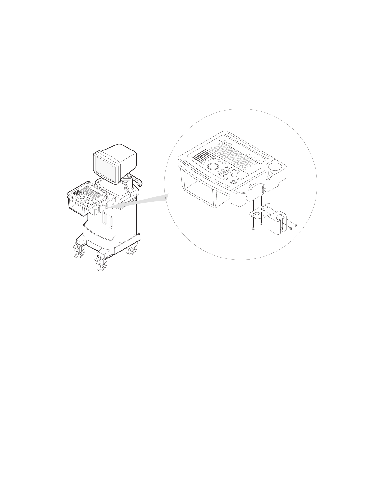
2–2–6 MTZ Probe Holder Installation (Option)
One MTZ probe holder and two brackets are supplied with the LOGIQ α200 console as shown in
ILLUSTRATION 2–4.
Note
Two sets of screw holes are provided at the bottom of standard probe holder and left side of
keyboard to install the MTZ probe holder. You can choose the most convenient position for your
customer between the two sets of screw holes.
MTZ Probe Holder
Bracket1 (Right)
Bracket 2 (Left)
MTZ PROBE HOLDER SET
ILLUSTRATION 2–4
2–1 1
INSTALLATION
Page 43
GE MEDICAL SYSTEMS
REV 0
LOGIQ α200 SERVICE MANUAL
2138853
2–2–6 MTZ Probe Holder Installation (Option) (Continued)
1. Assemble the MTZ probe holder at the bottom of standard probe holder by screwing four (1 – 4) screws as
shown in ILLUSTRATION 2–5.
MTZ PROBE HOLDER INSTALLATION (1)
ILLUSTRATION 2–5
2
1
4
3
2–12
INSTALLATION
Page 44
GE MEDICAL SYSTEMS
REV 0
LOGIQ α200 SERVICE MANUAL
2138853
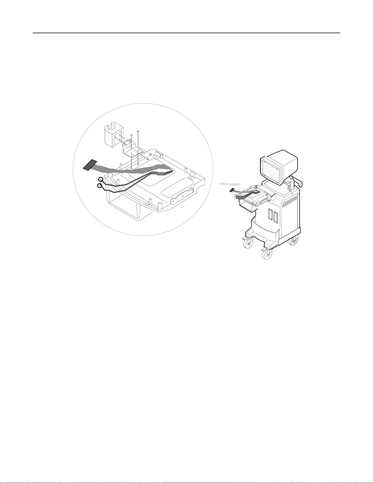
2–2–6 MTZ Probe Holder Installation (Option) (Continued)
2. After removing the Keyboard Assy (Refer to 6–2–10, 6–2 DISASSEMBLY/RE-ASSEMBL Y), Assemble the
MTZ probe holder at the left side of keyboard by screwing four (1 – 4) screws as shown in
ILLUSTRATION 2–6.
2
1
4
3
MTZ PROBE HOLDER INSTALLATION (2)
ILLUSTRATION 2–6
2–13
INSTALLATION
Page 45

GE MEDICAL SYSTEMS
REV 2
2–2–7 Transducer Connection
1. Connect a transducer to the left side connector slot #1, transducer receptacle as follows:
a. Ensure that the transducer twist lock lever points towards the 12 o’clock position.
b. Insert the transducer connector on the receptacle guide pin until it touches the receptacle mating surface.
c. Twist the transducer twist lock lever to the 4 o’clock position to lock it in place. Twist the lever to the 12
o’clock position to disconnect the transducer.
Note
It is not necessary to turn OFF power to connect or disconnect a transducer.
2. Connect the main power cable to a hospital grade power receptacle with the proper rated voltage checked
during preinstallation. Never use a three–to–two prong adapter; this defeats the safety ground.
2–2–8 Moving into Position
LOGIQ α200 SERVICE MANUAL
2138853
CAUTION
Do not lift the unit by the Keyboard.
Do not tilt the unit more than 5 degrees to avoid tipping it over.
To avoid injury by tipping over. Set the monitor to the lowest position before moving.
CAUTION
Equipment Damage Possibility. Lifting the console by holding covers may damage the
covers. Do not lift the console by holding any covers.
In general, a single adult can move the LOGIQ α200. (It is better to pull from the rear rather than push from the
front of the unit). Before moving, store all loose parts in the unit. Wrap transducers in soft cloth or foam to
prevent damage.
2–2–9 Adjusting System Clock
Set system clock for the LOGIQ α200to the local time. For procedure of adjusting the System clock, refer to
“Customizing Your System” in the Users manual.
2–14
INSTALLATION
Page 46

GE MEDICAL SYSTEMS
REV 2
LOGIQ α200 SERVICE MANUAL
2138853
2–2–10 Product Locator Installation Card
Fill out proper customer Information the Product Locator Installation Card. Refer to ILLUSTRATION 2–7. Mail
this Installation Card “Product Locator” to the address corresponding to your pole.
Note
The Product Locator Installation Card shown in ILLUSTRATION 2–7 may not be same as the
provided Product Locator card.
PRODUCT LOCATOR INSTALLATION CARD
ILLUSTRATION 2–7
2–15
INSTALLATION
Page 47

GE MEDICAL SYSTEMS
REV 0
3–1 INTRODUCTION
This chapter describes system configuration and specifications.
3–2 DIMENSIONS
LOGIQ
α200 SERVICE MANUAL
2138853
Regarding LOGIQ
WEIGHT: 76 kg
168 lbs
LENGTH : mm (inches)
ABERRATION : ±5%
350 (13.8)
α200 dimensions, Refer to ILLUSTRATION 3–1 for planning the position of your LOGIQ α200.
NOTE
400 (15.7)
663 (26.1)
250 (9.8)
245 (9.6)
335 (13.2)
192 (7.6)
1200 (47.2)
800 (31.5)
OVERALL DIMENSIONS
162 (6.4)
ILLUSTRATION 3–1
3–3
SYSTEM CONFIGURA TION
Page 48

GE MEDICAL SYSTEMS
REV 3
LOGIQ
α200 SERVICE MANUAL
2138853
3–3 ELECTRICAL SPECIFICA TIONS
Electrical conduit, junction boxes, outlets, circuit breakers, and switches should be in place before installing the
LOGIQ α200 console.
3–3–1 Power Supply
Voltage setup is performed in the factory. Different power cables and circuit breakers are used for the 100 (115)
Vac and 220 (240) Vac versions.
3–3–2 Facility Power Receptacle
A separate power outlet with a 10 amp circuit breaker for 100 (115) Vac units, or a 5 amp circuit breaker for 220
(240) Vac units, is recommended. The specific power receptacle used depends on your country’s power line
standards.
The receptacle should have International Electrotechnical Commission (IEC) approval, or equivalent.
3–4 STORAGE AND OPERATION REQUIREMENTS
Probes and peripherals are shipped in separate containers. Shipping weight is approximately 210 lbs (96 kg).
The size of the container is L82 cm x W53 cm x H140 cm (32 in. x 21 in. x 55 in). Table 3–1 provides a summary
of temperature, atmospheric pressure, and humidity tolerances for shipping, installation, and operation.
TABLE 3– 1
STORAGE AND OPERATION REQUIREMENTS
PARAMETER STORAGE OPERATION
TEMPERATURE (_C)
(_F)
ATMOSPHERIC PRESSURE
(hPa)
HUMIDITY (%)
(Non–condensing)
–10 to 60
14 to 140
700 to 1060 700 to 1060
5to90
10 to 40
50 to 104
5to90
3–4
SYSTEM CONFIGURA TION
Page 49

GE MEDICAL SYSTEMS
REV 3
LOGIQ
α200 SERVICE MANUAL
2138853
3–5 OPTIONAL PERIPHERALS
3–5–1 Peripherals/Accessories Connector Panel
LOGIQ α200 peripherals and accessories can be properly connected using the rear connector panel.
Located on the panel are video input and output connectors, camera expose connector, foot switch connector,
power connector and service tools.
This section indicates the pin assignment for each connector (1 – 4 in ILLUSTRATION 3–2) at pages 3–6 through 3–7.
Note
The optional ECG connector is available only for the console with the system software version
2.00 or later.
4
3
2
115V 1.7A Max
including front panel
100V 2.0A Max
including front panel
220–240V 0.8A Max
1
including front panel
REAR CONNECTOR PANEL
ILLUSTRATION 3–2
3–5
SYSTEM CONFIGURA TION
Page 50

GE MEDICAL SYSTEMS
REV 3
3–5–1 Peripherals/Accessories Connector Panel (Continued)
Note
Each outer (case) ground line of peripheral/accessory connectors are protectively grounded.
Signal ground lines are Not Isolated.
1. Pin Assignment of RS232C for Service
Connector : Female, D–SUB, 25–pin
LOGIQ
α200 SERVICE MANUAL
2138853
Pin No.
Signal Pin No. Signal
1 Frame GND 14
2 TXD 15
3 RXD 16
4 RTS 17
5 CTS 18
6 DSR 19
7 Signal GND 20 DTR
8 DCD 21
9 22 Ring Indicator
10 23
11 24
12 + 5 V*1(300mA Max) 25
13
*1
: This voltage shall be apply to this Pin in case of MODEM usage.
Note
Output level of RS232C signals :
High +3V to +15V
Low –15V to 0V
14
25
1
13
3–6
SYSTEM CONFIGURA TION
Page 51

GE MEDICAL SYSTEMS
REV 2
3–5–1 Peripherals/Accessories Connector Panel (Continued)
2. Pin Assignment of Foot Switch
Connector : Round 5–pin connector
LOGIQ
α200 SERVICE MANUAL
2138853
Pin No.
Output Signal Pin No. Output Signal
1 FOOT SW 4
2 FOOT SW_G 5 Frame GND
3
3. Pin Assignment of Mini Jack for Controlling B/W Printer
Connector :Stereo Mini Jack
Pin No.
1 PRINT
*1
: Printer starts printing by receiving the LOW pulse more than 100ms.
Output Signal Pin No. Output Signal
*1
2 Signal GND
Note
Output level of control signals indicated in the above tables are TTL level.
5
4
1
2
3
3–7
SYSTEM CONFIGURA TION
Page 52

GE MEDICAL SYSTEMS
LOGIQ
α200 SERVICE MANUAL
REV 3
3–5–2 List of Optional Peripherals
The tables below shows the suggested optional peripherals for LOGIQ α200.
1. RECORDING DEVICES
TABLE 3– 2
LIST OF RECORDING DEVICES
DEVICE MANUFACTURER MODEL CATALOG No. VIDEO SIGNAL
Video Cassette Recorder SONY SVO-9500MD Local NTSC
SONY SVO-9500MDP Local PAL
Video Graphic Printer SONY UP890 Local
MITSUBISHI P90 Local
Multi Image Camera International Imaging
Electronics
IIE460 Local
Note
See each option installation instructions for installation and connection procedures.
2138853
2. TRANSDUCER (PROBE)
TABLE 3– 3
LIST OF TRANSDUCERS
PROBE
NAME
CBF PES Abdom. Convex H46022CB Not Required P9603AA P9603AD
CAE PES Abdom. Convex H46022CA Not Required P9603AB P9603AE
MTZ PES Intercavity Convex H46022MT Not Required P9603AL P9603AU
CZB NORYL Neonatal Convex H45202CZ Not Required 2152402 2152422
CS PES Abdom. Convex H45222CS Not Required 2202315 2202320
ATR PES Urology Convex H4061PR Not Required 2201223 2201222
LH PES Superficial Linear H46022LH Not Required P9601AC P9601AS
LE PES OB/Gyn. Linear H46022LE Not Required P9601AB P9601AR
LT PES Intraoperative Linear H46022LT Not Required P9601AJ P9601AX
LB PES OB/Gyn. Linear H46022LB Not Required P9601AA P9601AQ
LD NORYL Intraoperative Linear H45202LD Not Required P9601AD 2124317
MATERIAL OF
HEADSHELL
LI PES Intraoperative Linear H46022LI Not Required P9601AG P9601AW
AREA OF USING TYPE CATALOG
NO.
REQUIRED
ADAPTER
PART NO.
FOR JAPAN
PART NO.
3–8
SYSTEM CONFIGURA TION
Page 53

GE MEDICAL SYSTEMS
REV 0
3–5–2 List of Optional Peripherals (Continued)
CAUTION
Equipment damage possibility. Be sure to use the following recommended connecting
cables to connect recording devices with LOGIQ α200 console.
1. CONNECTING CABLES
TABLE 3– 4
LIST OF CONNECTING CABLES
NAME PART NO. FIGURE NOTE
Printer Install Kit 2176459 Printer Cable Assy, BNC cable,
Shutter cable
LOGIQ
α200 SERVICE MANUAL
2138853
For B/W Printer
3–5–3 Power Consumption of Optional Peripherals
The table below shows the power consumption of each optional peripheral for LOGIQ α200.
TABLE 3– 5
POWER CONSUMPTION OF OPTIONAL RECORDING DEVICES
DEVICE MODEL POWER CONSUMPTION
Video Cassette Recorder SVO-9500MD 64 W
SVO-9500MDP
Video Graphic Printer UP890 110 W
Multi Image Camera IIE460 60 W
3–9
SYSTEM CONFIGURA TION
Page 54

GE MEDICAL SYSTEMS
REV 3
3–6 TEST POINT, LED, DIP SWITCH AND RESET SWITCH
3–6–1 Test Point List
The table below shows The Test Point list for LOGIQ α200.
TABLE 3– 6
TEST POINT
LOCATION NAME DESCRIPTION POSITION
DSC ASSY TP1 M–mode enable signal Edge of board
TP3 Mapping clock –
TP4 Horizontal driving signal –
TP5 Vertical driving signal –
TP6 Anti–alasing filter output –
TP7 Scan line No.0 –
TP8 Scan line No.8 –
TP9 –5V for analog/digital –
TP10 Input echo signal from the ESP
Assy
TP V5_1 +5V for digital Edge of board
MST ASSY TP601 Gnd Edge of board
TP602 +5V for digital Edge of board
FOOT S/W Foot switch status –
CLK2_25M 25MHz clock –
CLK 9M 9MHz clock –
CLK36M 36MHz clock –
RTC ASSY +5V +5V for digital Edge of board
+15V +15V for analog Edge of board
–15V –15V for analog Edge of board
THV High voltage for transmitting Edge of board
RTC_WE RTC write enable signal –
CDA D/A output for continuous
dynamic aperture (CDA)
CIM Not used –
CDF D/A output for continuous
dynamic focusing (CDF)
PGC D/A output for Pre–gain
control (PGC)
TFC D/A output for time frequency
control (TFC)
LOGIQ
α200 SERVICE MANUAL
2138853
–
–
–
–
–
3–10
SYSTEM CONFIGURA TION
Page 55

GE MEDICAL SYSTEMS
REV 2
3–6–1 Test Point List (continued)
The table below shows The Test Point list for LOGIQ α200.
TABLE 3– 7
TEST POINT
LOCATION NAME DESCRIPTION POSITION
RTC ASSY TGC Data Output for Time Gain
Control (TGC)
HV_REF Data output for HV control –
TRIGB Trigger signal –
HV ASSY TP_THV High Voltage for transmitting –
TP_SHV High Voltage for High Voltage
switch on CONN Assy
TP HV_REF D/A output for HV control –
ESP ASSY V–15 –15V for Analog Edge of board
V–5 –5V for analog/digital Edge of board
V5 +5V for digital Edge of board
CDA–H High position of aperture
reference voltage
CDA–L Low position of aperture
reference voltage
CDA–ADJ For Adjusting aperture refer-
ence voltage
CDFT–OUT Positive control voltage of
CDF
CDFN–OUT Negative control voltage of
CDF
CDF–ADJ For adjusting CDF control cir-
cuit
TFC–OUT Output of TFC control voltage –
TFC–ADJ For adjusting TFC control cir-
cuit.
TGC–OUT Output of TGC control voltage –
PGC–OUT Output of PGC control voltage –
OFFSET–
ADJ
For adjusting offset voltage of
Log Amp
FEC Output signal of Delay line
RFI Output of RFI filter –
D–OUT Output of dynamic filter –
NVE Output Signal of ESP Assy –
LOGIQ
α200 SERVICE MANUAL
2138853
–
–
Edge of board
Edge of board
–
–
–
–
–
3–1 1
SYSTEM CONFIGURA TION
Page 56

GE MEDICAL SYSTEMS
LOGIQ
α200 SERVICE MANUAL
REV 0
3–6–1 Test Point List (continued)
TABLE 3– 8
TEST POINT
LOCATION NAME DESCRIPTION POSITION
ESP ASSY TP3 GND
TP6 GND
V15 +15V for Analog
CONN ASSY +5V +5V for digital Edge of board
–15V –15V for analog Edge of board
SHV High voltage for high voltage
switch
2138853
Edge of board
3–12
SYSTEM CONFIGURA TION
Page 57

GE MEDICAL SYSTEMS
Not
REV 5
3–6–2 LED List
The table below shows the LED list for LOGIQ α200.
TABLE 3–7
LED
LOGIQ
α200 SERVICE MANUAL
2138853
LOCA TION NAME DESCRIPTION POSITION
NORMAL ABNORMAL
MST ASSY V5 +5V for digital Edge of board ON OFF
WOTOUT Watchdoc timer out, Reserved Edge of board – –
D3~D10 Reserved Edge of board – –
DSC ASSY DS1 +5V for digital Edge of board ON OFF
DS2 Mapping clock Edge of board Refer to
DS3 Mapping clock Edge of board
e
DS4 Mapping clock Edge of board
DS5 DSP running Edge of board ON OFF
HV ASSY DS1 HV ASSY status (ON:normal) Edge of board ON OFF
SMPS ASSY GREEN
LED
SMPS ASSY status (ON:nor-
mal)
SMPS ASSY ON OFF
Note
Three LED (DS2~DS4) should be blinked when the system operated with the Probe.
3–6–3 DIP Switch
The table below shows the DIP Switch list for LOGIQ α200.
NO
TABLE 3–8
DIP SWITCH Setting
LOCATION NAME Switch No. DESCRIPTION POSITION
MST ASSY S1 1 Initiate the SRAM data to factory
Edge of board
Setup value
7 Select AAF Filter
(ON:Other countries, OFF:Japan)
2~ 6 Not Assigned
8 Select NTSC or PAL (ON:PAL, OFF:NTSC)
DSC ASSY S1 1 ~8 Not Assigned Edge of board
3–6–4 Reset Switch
Reset switch (S2) on edge of MST Assy used for resetting the system.
3–13
SYSTEM CONFIGURA TION
Page 58

GE MEDICAL SYSTEMS
REV 2
4–1 INTRODUCTION
This chapter provides procedures for quickly checking major functions of the LOGIQ α200 console, and SMPS
adjustments.
4–1–1 Required Equipment
To perform these tests, you’ll need a linear , or a convex transducer.
4–2 FUNCTIONAL CHECK PROCEDURES
4–2–1 Basic Controls
LOGIQ α200 SERVICE MANUAL
2138853
Step Check Expected Result
1 Connect the convex transducer
to ”Probe 1” connector.
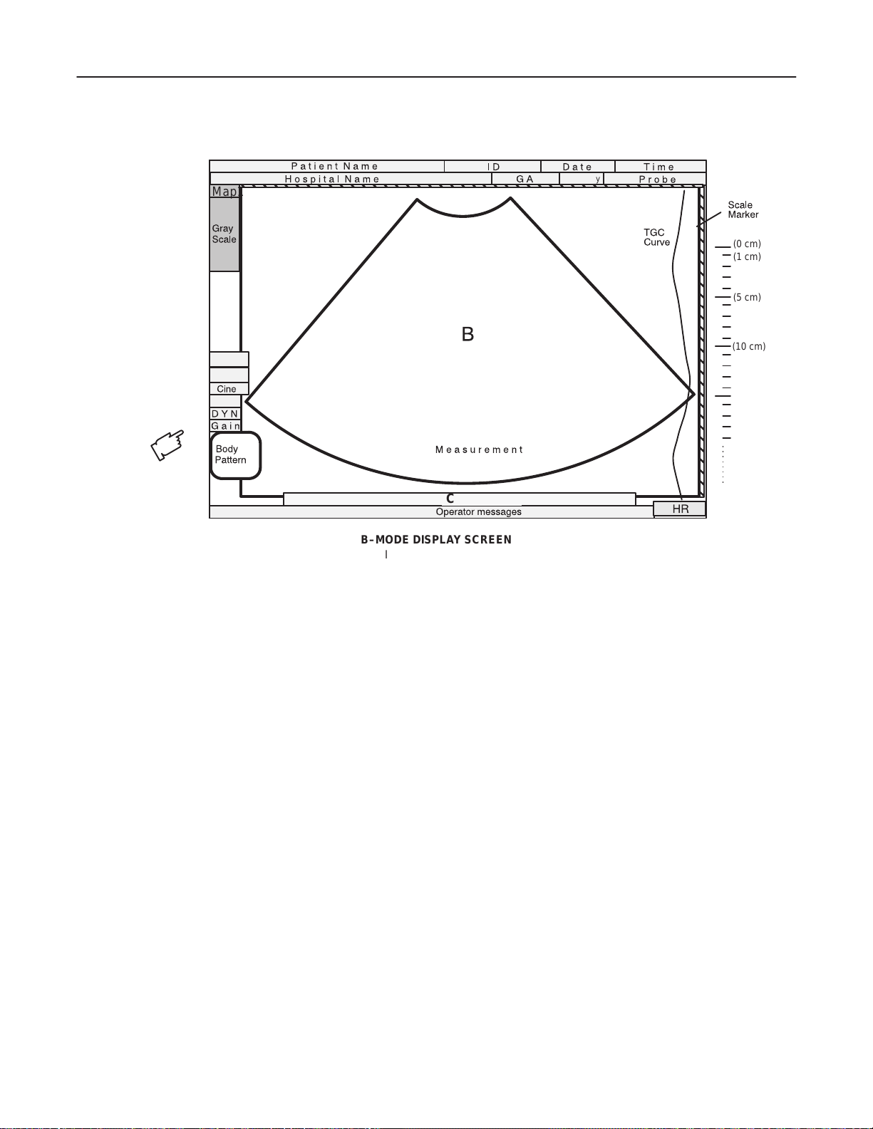
2 Power On After few seconds, the B mode screen should appears
as shown in ILLUSTRATION 4–1.
3 Rotate B/M Gain knob Image gets lighter with CW rotation and darker with
CCW.
4 Press Map key to select another
gray scale Map.
5 Press Dyn Range Arrow up or
down key.
6 Rotate Depth knob. The depth of image should be increased /decreased.
7 Slide TGC potentiometers (pots) Image grows darker or brighter at depth equivalent to
8 Press Zoom. key.
The gray scale adjusts to each new Map selected.
At lower Dynamic Range settings, image speckle
fades and prominent objects in the display are more
pronounced from the background image.
pot’s location.
The image should increase to X2 size.
Press it again to exit.
9 Press Frame Avg key . Image speckle fades and probe or wire movement is
smeared.
10 Press Edge Enhc key. The edges inside the focal area(s) should become
lighter when you increase and darker as you decrease
its value.
11 Press Reverse key. The image reverses the left/right orientation.
12 Press Reverse key again. The image reverses again.
4–3
FUNCTIONAL CHECKS
Page 59
GE MEDICAL SYSTEMS
REV 3
4–2–1 Basic Controls (Continued)
Map1
LOGIQ α200 SERVICE MANUAL
2138853
Category
GE
(0 cm)
(1 cm)
(5 cm)
FA
EE
FOV
(10 cm)
Cine Gauge
B–MODE DISPLAY SCREEN
ILLUSTRATION 4–1
4–4
FUNCTIONAL CHECKS
Page 60

GE MEDICAL SYSTEMS
REV 2
4–2–2 M-Mode Check
Step Check Expected Result
13
Press M key. The M mode timeline should appear next to the B
Roll trackball, position cursor
over area you want to see in
motion.
Press M key again. The full M-mode should appear on the CRT monitor.
LOGIQ α200 SERVICE MANUAL
2138853
image as shown in ILLUSTRATION 4–2. Whether it
takes half the screen or two–thirds depends on the
preset.
The Mode cursor should follow trackball movement
and the timeline should update for new location of
focus.
14
15
16
17
18
19
Rotate B/M Gain knob The M timeline should get brighter with CW rotation
and darker with CCW.
Press Dyn Range Arrow up or
down key.
Press Sweep Speed key
Press it again to exit.
Press Freeze key.
Press it again to exit.
Press Edge Enhc key. Changes the M image
Press B key. The M Mode timeline should disappear and the
Dynamic Range affects grays and the last added scan
mode; to adjust the basic B, M must be off. Turn
Dynamic Range down to increase contrast, turn up to
soften.
The timeline speed should increase to 4 second
sweeps and decrease to 16 second sweeps.
Fast=4 Medium=8 Slow=16
The image should freeze.
The image revives acquisition.
B-mode image should appear as shown in
ILLUSTRATION 4–1.
4–5
FUNCTIONAL CHECKS
Page 61

GE MEDICAL SYSTEMS
REV 3
4–2–2 M-Mode Check (Continued)
LOGIQ α200 SERVICE MANUAL
2138853
Map1
Category
GE
FA
EE
FOV
Cine Gauge Cine Gauge
M–MODE DISPLAY SCREEN
ILLUSTRATION 4–2
Note
You can select several types of display formats by using the Setup Menu. For the Preset Menu,
refer to Customizing Your System in the LOGIQ α200 User Manual.
M
4–6
FUNCTIONAL CHECKS
Page 62
GE MEDICAL SYSTEMS
REV 0
LOGIQ α200 SERVICE MANUAL
2138853
4–3 SMPS ADJUSTMENTS
This section provides SMPS adjustment procedures for the LOGIQ α200. Adjustments should be only made
when necessary. SMPS adjustments should be made in accordance with the schedule for periodic maintenance
in Chapter 7 of this manual.
Before beginning the SMPS adjustments procedure, make sure the power outlet conforms to the proper power
line standards. Refer to Chapter 2, Installation.
Note
If the adjustment pot is turned to far clockwise, the SMPS output shuts down to protect the circuits
against the over–voltage. In that case, power the LOGIQ
α200 OFF and turn the pot
counterclockwise all the way. Then power it ON and try to adjust the SMPS again.
The SMPS Assy is in the bottom of the LOGIQ α200 as shown in ILLUSTRATION 4–6.
4–3–1 SMPS Assy Access
1. Remove the four screw caps and unscrew the screws to remove the Left Cover as shown in the
ILLUSTRATION 4–3.
Left Cover
LEFT COVER REMOVAL
ILLUSTRATION 4–3
4–7
FUNCTIONAL CHECKS
Page 63

GE MEDICAL SYSTEMS
LOGIQ α200 SERVICE MANUAL
REV 0
4–3–1 SMPS Assy Access (Continued)
2. Remove the four screw caps and unscrew the screws to remove the Right Cover as shown in the
ILLUSTRATION 4–4.
Right Cover
2138853
RIGHT COVER REMOVAL
ILLUSTRATION 4–4
3. Remove the four screw caps and unscrew the screws to remove the Rear Cover as shown in the
ILLUSTRATION 4–5.
Rear Cover
REAR COVER REMOVAL
ILLUSTRATION 4–5
4–8
FUNCTIONAL CHECKS
Page 64

GE MEDICAL SYSTEMS
LOGIQ α200 SERVICE MANUAL
REV 0
4–3–2 SMPS Adjustment Procedure
1. Power LOGIQ α200 ON. Wait for about 30 seconds to warm up the console.
2. Connect a DVM to the appropriate place shown in Table 4–1.
3. Verify that the voltages are as shown in Table 4–2.
TABLE 4– 1
SMPS MEASUREMENT LOCATION
SMPS MEASURE AT RETURN AT ADJUST AT
+5V,± 15V for Analog V5 (+5V), V–15 (–15V), V15
(+15V) on ESP BD ASSY
–5V for Analog/Digital V–5 (–5V) on ESP BD ASSY TP3 (Ground) on ESP BD
+12 for Monitor B+ (+12V) on Monitor Input
Connector
+5V for Digital TP 602 (+5V) on MST BD
ASSY
TP3 (Ground) on ESP BD
ASSY
ASSY
GND on Monitor Input
Connector
TP 601 (GND) on MST BD
ASSY
2138853
1 on SMPS ASSY
See ILLUSTRATION 4–6
2 on SMPS ASSY
See ILLUSTRATION 4–6
3 on SMPS ASSY
See ILLUSTRATION 4–6
4 on SMPS ASSY
See ILLUSTRATION 4–6
TABLE 4–2
SMPS MEASUREMENT TOLERANCES
SMPS MIN MAX
+5V, ± 15V for Analog +4.8 V
–15.75V
+14.25 V
–5V for Analog/Digital –4.8 V –5.2 V
+12 for Monitor +1 1.8 V +12.2 V
+5V for Digital +4.8 V +5.2 V
+5.2 V
–14.25 V
+15.75 V
4–9
FUNCTIONAL CHECKS
Page 65

GE MEDICAL SYSTEMS
REV 0
4–3–2 SMPS Adjustment Procedure (Continued)
LOGIQ α200 SERVICE MANUAL
2138853
2
3
1
1. Adjustment Point for +5V, ±15V SMPS
2. Adjustment Point for –5V SMPS
3. Adjustment Point for +12V SMPS
4. Adjustment Point for +5V SMPS
SMPS ASSY
ILLUSTRATION 4–6
4
4–10
FUNCTIONAL CHECKS
Page 66

GE MEDICAL SYSTEMS
REV 0
5–1 INTRODUCTION
LOGIQ α200 SERVICE MANUAL
2138853
LOGIQ
α200 is a compact ultrasound scanner supporting a wide range of probes. This gives the system added
benefits and flexibility to meet diverse applications.
5–2 LOGIQ α200 SYSTEM
The LOGIQ α200 has a 48 channel beamformer that digitizes the RF signal. It uses analog delays to focus the
acoustic beam. It offers parallel receive beam formation which can increase frame rate by a factor of two in time
critical applications. This system also features many advanced image processing controls.
User surveys and the latest technology were used to increase console ease-of-use.
System Features
The key design goals of this system are:
• High Image Quality
• Increased User Productivity
• Multiple Clinical Applications
• Planned Upgradeability
• High Mobility
Types of Applications
The system supports many clinical uses. Scan and display parameters may be user selected to default to desired
values for each application. The system presets many parameters to clinically determined, optimal values.
• RAD/ABDOMEN
• OB/GYN
• UROLOGY
• SMALL P ARTS
• UROLOGY
• CARDIOLOGY
See Illustration 5–1, the LOGIQ
α200 system can be divided into an analog signal processing section, a digital
signal processing section. The digital section has the microprocessor driven system control section, which
controls the system based on operator commands and system status information.
5–3 DIAGRAMS
Page 67

GE MEDICAL SYSTEMS
REV 3
5–3 BLOCK DIAGRAM
LOGIQ α200 SERVICE MANUAL
2138853
Power
Supply
RTC
HV
To Mother board
To Mother board
To Mother board
MST
ESP
Rear
Panel
Keyboard
DSC
ECG
Shutter Control
Foot Switch
B/W Monitor
CONN
NOVA BUS
RTC BUS
LOGIQ α200 SYSTEM BLOCK DIAGRAM
ILLUSTRATION 5–1
5–4 DIAGRAMS
Page 68
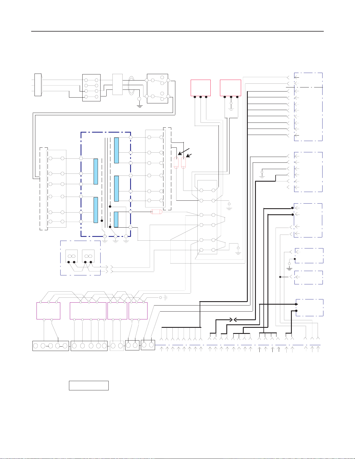
GE MEDICAL SYSTEMS
REV 0
5–4 WIRING DIAGRAM
LOGIQ α200 SERVICE MANUAL
2138853
PLUG
L(Brown)
N(Light Blue)
G(Green/Yellow)
TB2
7
8
9
10
11
12
TB1
1
2
3
4
N(Light Blue)
L(Brown)
ISOLATION TRANSFORMER
PRI SEC
4
0
100
5
115
6
1
0
100
2
115
3
FAN SET
:
NFB1
1
3
10A/115V
5A/220V
1715
100
115
100
115
110
Core
L
2
4
N
POWER SW
AC OUTLET B/W PRT
LNG
NLG
J30
J31
TB2
1
9
0
2
8
3
7
12
0
11
10
0
16
4
5
6
NFB2
3A
Orange
Gray
NFB3
NFB4
2A/115V
1A/220V
TB3
1
2
3
4
5
6
HV ASSY
GND
2
AC110 V
1
GND
1
GND
2
SHV
3
HV–REF
4
THV
5
N.C.
6
– 15 V
7
15 V
8
MON ASSY
+12V
3
5
GND
FG
1
2
MON_VID
4
RTN
N.C.
6
REAR PANEL
F SW/SHTR
EXT_VID
RS232C
ECG
KEY B’D
CN01
FG L N FG
LN
HK50A–5/A HKT75–5FF/A HK25A–5/A HK50A–12/A
+5V G –15V +5V+15V G2G1
1 2 3 4 5
N
+
+
.
5
5V
C
VD
D
.
J10 J13 J11 J28 J29
1 2 3 4 5 1 2
–
G
G
N
N
D
D
+
15
15
VA
VA
+
G
G
5
N
N
VA
D
D
LN
+5VG
–
5V
FG
LN
+12V G
1 2
+
G
G
12
N
N
V
D
D
MOTHER B’D
LOGIQ
FG
12 34 5678
1 2
+
G
S
12
V
G
N
H
N
D
V
D
T
–
H
H
V
V
–
–
S
R
T
E
S
F
+
G
H
15
15
N
V.
V
V
D
α200 SYSTEM WIRING DIAGRAM
ILLUSTRATION 5–2
CN02
1212 34
M
R
O
T
N
N
–
V
I
D
12
E
R
P
R
R
T
T
N
–
V
I
D
E
R
X
T
X
T-
N
T-
N
V
V
I
I
D
D
–
–
I
I
N
N
ECG
B/W PRINTER
PRT_VID
SHTR
34
12
F
F
O
O
T
O
O
T
T
S
S
W
W
–
J8J6J5J4J12
G
12
S
S
S
H
H
H
T
T
T
R
R
R
–
G
R
S
H
T
R
–
G
J9
K
S
E
2
Y
3
B
2
’
C
D
J2 J1 J7
E
C
G
5–5 DIAGRAMS
Page 69

GE MEDICAL SYSTEMS
REV 0
5–4 WIRING DIAGRAM (Continued)
LOGIQ α200 SERVICE MANUAL
2138853
Brown
Brown
Light Blue
Light Blue
Orange
Orange
Gray
Gray
TB2
12
11
10
9
8
7
6
5
4
3
2
1
(100 V)
TB2
115V
100V
0V
115V
100V
0V
115V
100V
0V
115V
100V
0V
AC IN
Peripheral
Out
Brown
Brown
Light Blue
Light Blue
Orange
Orange
Gray
Gray
TB2
12
11
10
9
8
7
6
5
4
3
2
1
(115 V)
TB2
115V
100V
0V
115V
100V
0V
115V
100V
0V
115V
100V
0V
AC IN
Peripheral
Out
Brown
Brown
Light Blue
Orange
Orange
Gray
12
11
10
9
8
7
6
5
4
3
2
1
(220 – 240 V)
115V
100V
0V
115V
100V
0V
115V
100V
0V
115V
100V
0V
LOGIQ
Brown
AC IN
Peripheral
Out
α200 SYSTEM WIRING DIAGRAM (CONTINUED)
ILLUSTRATION 5–3
Brown
Light Blue
Orange
Orange
Gray
Gray
12
11
10
9
8
7
6
5
4
3
2
1
(INPUT: 220 – 240 V
OUTPUT: 115 V)
115V
100V
0V
115V
100V
0V
115V
100V
0V
115V
100V
0V
AC IN
Peripheral
Out
5–6 DIAGRAMS
Page 70

GE MEDICAL SYSTEMS
REV 0
LOGIQ α200 SERVICE MANUAL
2138853
5–5 CIRCUIT BOARD DESCRIPTION
The following table lists circuit boards and their respective card cage slot assignments on the mother board of the
LOGIQ
α200 system.
CARD CAGE SLOT
TABLE 5– 1
CIRCUIT BOARD DESCRIPTION
BOARD NAME DESCRIPTION NOTE
1 ESP BD ASSY Echo Signal Processor Board Assembly
2 RTC BD ASSY Real Time Controller Board Assembly
3 DSC BD ASSY Digital Scan Convertor Board Assembly
4 MST BD ASSY Master Board Assembly
CONN BD ASSY Connector Board Assembly
HV BD ASSY High Voltage Board Assembly
MOTHER ASSY Motherboard Assembly
5–7 DIAGRAMS
Page 71

GE MEDICAL SYSTEMS
REV 4
6–1 RENEW AL PARTS
LOGIQ α200 SERVICE MANUAL
2138853
LOGIQ a200
MATERIAL LIST (1/3)
PART NAME
OPERATOR CONSOLE ASSY 2157726 1 220V, NTSC, 4 SWIVEL VER0.3
OPERATOR CONSOLE ASSY 2157727 1 100V, NTSC, 4 SWIVEL VER0.3
OPERATOR CONSOLE ASSY 2157728 1 115V, NTSC, 4 SWIVEL VER0.3
OPERATOR CONSOLE ASSY 2157729 1 1 220V, PAL, 4 SWIVEL VER0.3
OPERATOR CONSOLE ASSY 2157858 1 220V, PAL, 4 SWIVEL VER0.3
OPERATOR CONSOLE ASSY 2157730 1 115V, NTSC, 2 SWIVEL VER0.3
OPERATOR CONSOLE ASSY 2157731 1 220V, PAL, 2 SWIVEL VER0.3
OPERATOR CONSOLE ASSY 2157732 1 220V, NTSC, 2 SWIVEL VER0.3
CABLE HOOK ARM 2170597 111111111
MTZ HOLDER ASSY 2175435 RIGHT
MTZ HOLDER ASSY 2175436 LEFT
FOOT SWITCH ASSY 2162242
CINE 2174971 1 1 1 1 1
PRINTER INSTALL KIT 2176459 111111111
PART NO.
QUANTITY
DESCRIPTION
OPERATOR MANUAL 2138852–100 1 1 1 1 1 1 1 English
SERVICE MANUAL 2138853 1 1 1 English
QUICK MANUAL 2164878–100 1 1 1 English
KOREA
JAPAN
TAIWAN,PHILLIPPINES
CHINA, HONG KONG, SOUTHEAST ASIA
INDIA,AUSTRALIA,NEW ZEALAND
6–3 RENEWAL P ARTS
CHILE
BRAZIL
USA, CANADA, MEXICO
EUROPE
Page 72

GE MEDICAL SYSTEMS
REV 4
6–1 RENEW AL PARTS (continued)
LOGIQ α200 SERVICE MANUAL
2138853
LOGIQ α200
MATERIAL LIST (2/3)
PART NAME
OPERATOR CONSOLE ASSY 2184999 1 220V, NTSC, 4 SWIVEL VER1.1
OPERATOR CONSOLE ASSY 2185000 1 100V, NTSC, 4 SWIVEL VER1.1
OPERATOR CONSOLE ASSY 2185001 1 115V, NTSC, 4 SWIVEL VER1.1
OPERATOR CONSOLE ASSY 2185002 1 1 220V, PAL, 4 SWIVEL VER1.1
OPERATOR CONSOLE ASSY 2183920 1 220V, PAL, 4 SWIVEL VER1.1
OPERATOR CONSOLE ASSY 2184519 1 115V, NTSC, 2 SWIVEL VER1.1
OPERATOR CONSOLE ASSY 2184520 1 220V, PAL, 2 SWIVEL VER1.1
OPERATOR CONSOLE ASSY 2184521 1 220V, NTSC, 2 SWIVEL VER1.1
CABLE HOOK ARM 2170597 111111111 Include hook arm space
MTZ HOLDER ASSY 2175435 RIGHT
MTZ HOLDER ASSY 2175436 LEFT
FOOT SWITCH ASSY 2162242 1 1 1
CINE 2174971 1 1 1 1 1 1
PRINTER INSTALL KIT 2176459 111111111
PART NO.
QUANTITY
DESCRIPTION
OPERATOR MANUAL 2183922–100 1 1 1 1 1 1 1 English
SERVICE MANUAL 2138853 1 1 1 1 English
QUICK MANUAL 2164878–100 1 1 1 English
KOREA (H43002LA)
JAPAN (H43002LJ)
TAIWAN,PHILLIPPINES (H43002LC)
CHINA, HONG KONG, SOUTHEAST ASIA (H43012LA)
INDIA,AUSTRALIA,NEW ZEALAND (H43002LD)
(H43002LT) USA, CANADA, MEXICO
6–4 RENEWAL P ARTS
(H43002LS) CHILE
(H43002LW) BRAZIL
(H43012LC) EUROPE
Page 73

GE MEDICAL SYSTEMS
REV 5
6–1 RENEW AL PARTS (continued)
LOGIQ α200 SERVICE MANUAL
2138853
LOGIQ a200
MATERIAL LIST (3/3)
PART NAME
CONSOLE ASSY 2205669 1 220V, NTSC, 4SW, VER 2.01
CONSOLE ASSY 2205670 1 100V, NTSC, 4SW, VER 2.01
CONSOLE ASSY 2205671 1 115V, NTSC, 4SW, VER 2.01
CONSOLE ASSY 2205672 1 1 220V, PAL, 4SW, VER 2.01
CONSOLE ASSY 2205674 1 1 220V, PAL, 4SW, VER 2.01
CONSOLE ASSY 2205675 1 115V, NTSC, 2SW, VER 2.01
CONSOLE ASSY 2205676 1 220V, PAL, 2SW, VER 2.01
CONSOLE ASSY 2205677 1 220V, NTSC, 2SW, VER 2.01
PROBE CABLE ARM 2215992 1 1 1
2.0 UPGRADE KIT 2217555 Include CINE
2.0 UPGRADE KIT 2211832
CABLE HOOK ARM 2170597 1 11111 1111Include hook arm space
MTZ HOLDER ASSY 2175435 RIGHT
MTZ HOLDER ASSY 2175436 LEFT
FOOT SWITCH ASSY 2162242 1 1 1
CINE 2174971 1 1 1 1 1 1 1
PRINTER INSTALL KIT 2176459 1 11111 1111
VINYL COVER 2189467 1
INSITE KIT 2208446
OPERATOR MANUAL
SERVICE MANUAL 2138853 1 1 1 1 1 English
QUICK MANUAL
SONY B/W PRINTER 2215797 1 1 1
ECG INSTALL KIT 2208447
L500 ECG CABLES P9509KH Clip type
ECG CABLE SET 2137161 Rod type
ECG CABLE ASSY P9509KG Japan only, Clip type
ECG CABLE ASSY 2137160 Japan only, Rod type
PART NO.
2200294–100 1 1 1 1 1 1 1 English
2206747–100 1 1 1 English
QUANTITY
DESCRIPTION
KOREA (H43022LA)
JAPAN
T AIW AN. PHILIPPINES
CHINA, HONGKONG, INDIA,
(H43022LB)
(H43022LC)
(H43022LD)
SOUTHEAST ASIA, AUSTRALIA
EUROPE
(H43022LF)
(H43022LE)
CHILE
(H43022LK)
BRAZIL
EUROPE
(H43022LJ)
(H43022LH)
USA
(H43022LG)
6–5 RENEWAL P ARTS
Page 74

GE MEDICAL SYSTEMS
REV 5
LOGIQ α200 SERVICE MANUAL
2138853
This page is left blank intentionally.
6–6 RENEWAL P ARTS
Page 75

GE MEDICAL SYSTEMS
REV 4
OPERATOR CONSOLE ASSY
KEYBOARD BLOCK
(FRU 201 – 204)
See ILLUSTRATION 6–3
LOGIQ α200 SERVICE MANUAL
2138853
MONITOR BLOCK
FRU 100 – 105
See ILLUSTRATION 6–2
PC BOARDS(2)
See ILLUSTRATION 6–4
BODY BLOCK
See ILLUSTRATION 6–5
PC BOARDS(1)
See ILLUSTRATION 6–4
POWER SUPPLY BLOCK
See ILLUSTRATION 6–6
ILLUSTRATION 6–1
6–7 RENEWAL P ARTS
Page 76

GE MEDICAL SYSTEMS
REV 4
OPERATOR CONSOLE ASSY 1/7
101
LOGIQ α200 SERVICE MANUAL
2138853
102
106
103
104
105
ILLUSTRATION 6–2
6–8 RENEWAL P ARTS
Page 77

GE MEDICAL SYSTEMS
REV 5
LOGIQ α200 SERVICE MANUAL
2138853
LOGIQ a200
2157726, 2157727, 2157728, 2157729, 2157858, 2157730, 2157731, 2157732
2184999, 2185000, 2185001, 2185002, 2183920, 2184519, 2184520, 2184521
2205669, 2205670, 2205671, 2205672, 2205674, 2205675, 2205676, 2205677
MATERIAL LIST (1/7)
FRU
NO. PART NAME PART NO QTY.FRU DESCRIPTION
100 MONITOR ASSY (NTSC) 2167603–2 1 1 Including Caution Label
, Plastic Filter
MONITOR ASSY (PAL) 2167604–2 1 1 Including Caution Label
, Plastic Filter
MONITOR ASSY (NTSC) 2167605–2 1 1 Including Caution Label
, Glass Filter
For America (USA,
Chile)
MONITOR ASSY (PAL) 2167606–2 1 1 Including Caution Label
, Glass Filter
For America (Brazil)
101 POT SET ASSY 2148193 1 2 Bright and Contrast,
Include Knob
102 CRT FILTER (PLASTIC) 2175437 1 2 Include 2 brackets
For Japan, Taiwan,
Phillippines, China,
Hongkong, India,
Southeast Asia,
Australia, Europe.
CRT FILTER (GLASS) 2175438 1 2 Include 2 brackets
For USA, Brazil, Chile,
Korea.
103 MONITOR COVER SET 2148195 1 2 Front, Rear, Bottom 6–2–4
104 TIL T ASSY 2148196 1 2 6–2–5
105 MONITOR SPACE PLA TE 2148197 1 1 White Plastic Washer 6–2–6
106 FIL TER CLAMP SET 2214397 1 2 For Plastic Filter 6–2–3
2214398 For Glass Filter
SECTION FOR
REFERENCE
6–2–1
6–2–1
6–2–1
6–2–1
6–2–2
6–2–3
6–2–3
6–9 RENEWAL P ARTS
Page 78
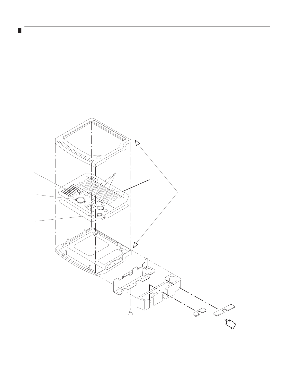
GE MEDICAL SYSTEMS
REV 5
OPERATOR CONSOLE ASSY 2/7
LOGIQ α200 SERVICE MANUAL
2138853
206, 209
205
208
207
211
203
204
202
201
PG Rivet
ILLUSTRATION 6–3
210
6–10 RENEW AL PARTS
Page 79

GE MEDICAL SYSTEMS
REV 5
LOGIQ α200 SERVICE MANUAL
2138853
LOGIQ a200
2157726, 2157727, 2157728, 2157729, 2157858, 2157730, 2157731, 2157732
2184999, 2185000, 2185001, 2185002, 2183920, 2184519, 2184520, 2184521
2205669, 2205670, 2205671, 2205672, 2205674, 2205675, 2205676, 2205677
MATERIAL LIST (2/7)
FRU
NO.
201 PROBE HOLDER 2175439 1 2 Include Probe Cup
202 HOLDER BRACKET ASSY 2148199 1 2 Include PG Rivet 6–2–8
203 KEYBOARD COVER SET 2148200 1 2 Top, Bottom with Holder
204 KEYBOARD ASSY 2158943–1 1 1 Include FRU 205–208 6–2–10
205 TRACKBALL ASSY 2174984 1 1 6–2–11
206 TGC ASSY 2174985 1 1 6–2–12
207 ENCODER SET 2174986 1 1 6–2–13
208 FREEZE/RECORD KEY ASSY 2174987 1 1 6–2–14
209 TGC KNOB SET 2214594 1 2 8 Knobs 6–2–15
210 PROBE PROTECTOR SHEET SET 2238146 1 1 2 sizes of inserts 6–2–16
211 KEY SHEET ASSY 2229673 1 1 6–2–17
PART NAME PART NO QTY. FRU DESCRIPTION
Holder and Probe Sheet
Brkt In
2158943–2 1 1 For S/W Version 2.0 6–2–10
SECTIO
N FOR
REFERE
NCE
6–2–7
6–2–9
6–11 RENEWAL PARTS
Page 80

GE MEDICAL SYSTEMS
REV 4
OPERATOR CONSOLE ASSY 3/7
LOGIQ α200 SERVICE MANUAL
2138853
309
301–304
308
306
305
307
ILLUSTRATION 6–4
6–12 RENEW AL PARTS
Page 81

GE MEDICAL SYSTEMS
REV 5
LOGIQ α200 SERVICE MANUAL
2138853
LOGIQ α200
2157726, 2157727, 2157728, 2157729, 2157858, 2157730, 2157731, 2157732
2184999, 2185000, 2185001, 2185002, 2183920, 2184519, 2184520, 2184521
2205669, 2205670, 2205671, 2205672, 2205674, 2205675, 2205676, 2205677
MATERIAL LIST (3/7)
FRU
NO. PART NAME PART NO QTY. FRU DESCRIPTION
301 MST ASSY 2185497–3 1 1 Version 1.2 software 6–2–18
2211942–5 1 1 Version 2.01 software 6–2–18
302 DSC ASSY 2148203–2 1 1 Version 1.2 software 6–2–18
2199767–2 1 1 Version 2.01 software 6–2–18
2243263 1 1 Version 1.2 software
(including Cine)
2243262 1 1 Version 2.01 software
(including Cine)
303 RTC ASSY 2185498 1 1 Version 1.2 software 6–2–18
2218506 1 1 Version 2.0 software 6–2–18
2218506–2 1 1 Version 2.01 software 6–2–18
304 ESP ASSY 2148205–3 1 1 Version 1.2 software 6–2–18
2206668 1 1 Version 2.0 software 6–2–18
305 HV ASSY 2148206–2 1 1 6–2–19
306 CONN ASSY 2148207 1 1 Include Bracket Probe 6–2–20
307 SHIELD P ANEL 2148208 1 2 6–2–21
308 MOTHER ASSY 2148210 1 1 6–2–22
309 NEST BOX 2205822 1 2 6–2–25
SECTION
FOR
REFERENCE
6–2–18
6–2–18
6–13 RENEW AL PARTS
Page 82

GE MEDICAL SYSTEMS
REV 4
OPERATOR CONSOLE ASSY 4/7
LOGIQ α200 SERVICE MANUAL
2138853
413
408
415
416
402
404
421
401
409
403
407
405
406
417
422
414
412
411
419
410
420
418
ILLUSTRATION 6–5
6–14 RENEW AL PARTS
Page 83

GE MEDICAL SYSTEMS
REV 5
LOGIQ α200 SERVICE MANUAL
2138853
LOGIQ a200
2157726, 2157727, 2157728, 2157729, 2157858, 2157730, 2157731, 2157732
2184999, 2185000, 2185001, 2185002, 2183920, 2184519, 2184520, 2184521
2205669, 2205670, 2205671, 2205672, 2205674, 2205675, 2205676, 2205677
MATERIAL LIST (4/7)
FRU
NO.
401 SWING ARM ASSY 2148212 1 1 6–2–24
402 PIPE ASSY 2148213–2 1 1 Include Cable Assy 6–2–25
403 POLE COVER 2148214 1 2 Include Cover Pole,
404 LEFT COVER 2158024 1 1 6–2–27
405 RIGHT COVER 2158053 1 1 6–2–28
406 FRONT BASE COVER 2148217 1 1 6–2–29
407 FRONT COVER 2148218 1 1 6–2–30
408 REAR COVER 2175441 1 2 Include Caution Label 6–2–31
409 TOP COVER 2158086 1 1 6–2–32
410 PRINTER COVER 2148220 1 2 6–2–32
411 PRINTER BRACKET ASSY 2167717 1 2 For Korea, Taiwan,
PRINTER BRACKET ASSY 2167718 1 2 For Japan 6–2–34
PRINTER BRACKET ASSY 2167719 1 2 For China, Hongkong,
412 BACK BRACKET ASSY 2169268 1 2 Include Printer Panel For
BACK BRACKET ASSY 2169269 1 2 Include Printer Panel For
BACK BRACKET ASSY 2169270 1 2 Include Printer Panel For
PART NAME
PART NO
QTY. FRU DESCRIPTION
Curtain Pole
Phillippines, USA, Chile
Southeast Asia, India,
Auatralia, Europe, Brazil
Korea, Taiwan,
Phillippines, USA, Chile
Japan
China, Hongkong,
Southeast Asia, India,
Auatralia, Europe, Brazil
SECTION FOR
REFERENCE
6–2–26
6–2–34
6–2–34
6–2–34
6–2–34
6–2–34
6–15 RENEW AL PARTS
Page 84

GE MEDICAL SYSTEMS
Philli ines, China, Hongkong
For USA, Brazil, Chile
REV 5
LOGIQ α200 SERVICE MANUAL
2138853
LOGIQ a200
2157726, 2157727, 2157728, 2157729, 2157858, 2157730, 2157731, 2157732
2184999, 2185000, 2185001, 2185002, 2183920, 2184519, 2184520, 2184521
2205669, 2205670, 2205671, 2205672, 2205674, 2205675, 2205676, 2205677
MATERIAL LIST (4/7)(Continued)
FRU
NO.
413 REAR HANDLE 2148222 1 2 6–2–35
414 NECK FRAME 2148223 1 2 6–2–36
415 REAR P ANEL ASSY 2167619 1 1 For Korea, Taiwan,
REAR P ANEL ASSY 2167620 1 1 For Japan 6–2–37
REAR P ANEL ASSY 2167621 1 1 For China, Hongkong,
416 POWER S/W ASSY 2148226 1 1 6–2–38
417 AC FAN ASSY 2175652 1 1 Ver 0.3, Ver 1.1 6–2–39
418 FRONT CASTER 2148228 2 1 6–2–40
419 REAR CASTER 2148051 2 1 Swivel
PART NAME
PART
NO
2206020 Ver 2.0
2245589 Ver 2.01
2192111
2192112
QTY. FRU DESCRIPTION
Phillippines, USA, Chile
Southeast Asia, India,
Auatralia, Europe, Brazil
For Japan, Taiwan,
pp
Southeast Asia, India,
Auatralia, Europe
SECTION FOR
REFERENCE
6–2–37
6–2–37
6–2–41
,
REAR CASTER 2161575 2 2 Fixed
420 BUMPER SET 2148230 1 2 6–2–42
421 EMI COVER L 2169025 1 2 6–2–43
422 PCB GUIDE ASSY 2169263 1 2 6–2–44
For USA, Brazil, Chile
2192113
6–16 RENEW AL PARTS
Page 85

GE MEDICAL SYSTEMS
REV 4
LOGIQ α200 SERVICE MANUAL
2138853
This page is left blank intentionally.
6–17 RENEW AL PARTS
Page 86

GE MEDICAL SYSTEMS
REV 4
OPERATOR CONSOLE ASSY 5/7
LOGIQ α200 SERVICE MANUAL
2138853
504
503
501
502
505
ILLUSTRATION 6–6
6–18 RENEW AL PARTS
Page 87

GE MEDICAL SYSTEMS
REV 5
LOGIQ α200 SERVICE MANUAL
2138853
LOGIQ a200
2157726, 2157727, 2157728, 2157729, 2157858, 2157730, 2157731, 2157732
2184999, 2185000, 2185001, 2185002, 2183920, 2184519, 2184520, 2184521
2205669, 2205670, 2205671, 2205672, 2205674, 2205675, 2205676, 2205677
MATERIAL LIST (5/7)
FRU
NO.
501 TERMINAL BLOCK 12 ASSY 2148231 1 2 12 pins 6–2–45
502 TERMINAL BLOCK 6 ASSY 2148232 1 2 6 pins 6–2–46
503 SMPS ASSY 2148233 1 1 6–2–47
504 POWER TRANS ASSY
(INPUT:220V–OUTPUT:115V)
POWER TRANS ASSY
(INPUT:100V–OUTPUT:100V)
POWER TRANS ASSY
(INPUT:115V–OUTPUT:1 15V)
POWER TRANS ASSY
(INPUT:220V–OUTPUT:220V)
505 CIRCUIT BREAKER SET 2174991 1 1 2A(2),3A, 5A ,
CIRCUIT BREAKER SET 2174992 1 1 2A(2), 3A, 10A
CIRCUIT BREAKER SET 2174993 1 1 1A(2), 3A, 5A
PART NAME PART NO QTY. FRU DESCRIPTION
2167617 1 1 For Korea, Chile 6–2–48
2167618 1 1 For Japan 6–2–48
2170698 1 1 For Taiwan,
Phillippines, USA
2170699 1 1 For China, Hongkong,
India, Southeast Asia,
Australia, Europe, Brazil
For Korea, Chile
For Japan, Taiwan,
Phillippines, USA
For China, Hongkong,
India, Southeast Asia,
Australia, Europe, Brazil
SECTION FOR
REFERENCE
6–2–48
6–2–48
6–2–49
6–2–49
6–2–49
6–19 RENEW AL PARTS
Page 88

GE MEDICAL SYSTEMS
REV 5
LOGIQ α200 SERVICE MANUAL
2138853
LOGIQ a200
2157726, 2157727, 2157728, 2157729, 2157858, 2157730, 2157731, 2157732
2184999, 2185000, 2185001, 2185002, 2183920, 2184519, 2184520, 2184521
2205669, 2205670, 2205671, 2205672, 2205674, 2205675, 2205676, 2205677
MATERIAL LIST (6/7)
FRU
NO.
601 FUSE SET 2148236 1 1
602 FLAT CABLE SET 2148237 1 1 Cable Assy 49, 51
603 CABLES SET 2148238 1 1 Cable Assy
604 HARDWARE SET 2148239 1 2 2157994, 2166804(4),
605 CABLE HOOK ARM SET 2170597 1 2 Include Washer
606 TOP COVER SHEET 2158087 1 2
607 BATTERY 2160331 1 1 3V, CR2450 7–2–4
PART NAME PART NO QTY. FRU DESCRIPTION
1A(250V), 500mA(250V),
2A(125V)
2, 3, 5, 6, 7, 8, 9, 10,
11, 12, 13, 14, 15, 16,
17, 19, 20, 21, 22, 23,
24, 25, 26, 27, 28, 29,
30, 31, 32, 33, 37, 39,
40, 41, 42, 43, 44, 45,
46, 47, 48, 61, 62, 63,
64, 65
2157951(12), 2158063,
2157971, 2157973,
2158077(2), 2160325,
2159642(10) ,
2159634(10) ,
2159625(10) ,
2162241(10) ,
2173177(5)
SECTION FOR
REFERENCE
6–3
6–20 RENEW AL PARTS
Page 89

GE MEDICAL SYSTEMS
REV 4
LOGIQ α200 SERVICE MANUAL
2138853
LOGIQ a200
2157726, 2157727, 2157728, 2157729, 2157858, 2157730, 2157731, 2157732
2184999, 2185000, 2185001, 2185002, 2183920, 2184519, 2184520, 2184521
2205669, 2205670, 2205671, 2205672, 2205674, 2205675, 2205676, 2205677
MATERIAL LIST (7/7)
FRU
NO.
701 CBF PROBE P9603AD 1 1
702 CAE PROBE P9603AE 1 1
703 MTZ PROBE P9603AU 1 1
704 CZB PROBE 2152422 1 1
705 LH PROBE P9601AS 1 1
706 LE PROBE P9601AR 1 1
707 LI PROBE P9601AW 1 1
708 L T PROBE P9601AX 1 1
709 LB PROBE P9601AQ 1 1
710 LD PROBE 2124317 1 1
711 FOOT SWITCH ASSY 2162242 1 2
712 MTZ HOLDER ASSY 2175435 1 2
713 MTZ HOLDER ASSY 2175436 1 2
714 A TR PROBE 2201222 1 1
715 CS PROBE 2202320 1 1
PART NAME PART NO QTY. FRU DESCRIPTION
P9603AA 1 1
P9603AB 1 1
P9603AL 1 1
2152402 1 1
P9601AC 1 1
P9601AB 1 1
P9601AG 1 1
P9601AJ 1 1
P9601AA 1 1
P9601AD 1 1
2201223 1 1
2202315 1 1
SECTION FOR
REFERENCE
For Japan Only
For Japan Only
Not Include MTZ HOLDER
ASSY
Not Include MTZ HOLDER
ASSY
For Japan Only
For Japan Only
For Japan Only
For Japan Only
For Japan Only
For Japan Only
For Japan Only
For Japan Only
Right
Left
For Japan Only
For Japan Only
6–21 RENEW AL PARTS
Page 90

GE MEDICAL SYSTEMS
REV 4
6–2 DISASSEMBLY/RE-ASSEMBLY
ONLY QUALIFIED SERVICE PERSONNEL SHOULD REMOVE ANY COVERS OR PANELS.
ELECTRICAL HAZARDS EXISTS AT SEVERAL POINTS INSIDE. BECOME THOROUGHLY
FAMILIAR WITH ALL HAZARDOUS VOLTAGES AND HIGH CURRENT LEVELS TO AVOID
ACCIDENTAL CONTACT
Do not wear the ESD wrist strap when you remove the SMPS Assy. Turn OFF power and
unplug the power cord before removing any part of SMPS Assy. However be sure to turn off
power and wear the strap before you remove a circuit boards.
LOGIQ α200 SERVICE MANUAL
2138853
W ARNING!
CAUTION
CAUTION
Do NOT unplug the power cord before turning OFF the power switch.
6–23 RENEW AL PARTS
Page 91

GE MEDICAL SYSTEMS
REV 4
6–2–1 Monitor Assy (FRU No. 100)
Time Required
5 Minutes
Tool Required
Screwdriver
Procedure
PERSONAL INJURY HAZARD. VIDEO MONIT OR SUPPORT ARM IS SPRING LOADED.
RELEASING ARM WHEN MONITOR IS NOT INST ALLED WILL CAUSE SUDDEN UPWARD
MOVEMENT. KEEP YOUR HEAD AND BODY AWAY FROM ABOVE VIDEO MONITOR
SUPPORT ARM.
LOGIQ α200 SERVICE MANUAL
2138853
WARNING!
Refer to ILLUSTRATION 6–7.
1. Turn OFF the system.
2. Lift and set the Monitor to the highest position by pushing down the Up/down Release Button located on the
Swing Arm Assy .
3. Remove the Monitor Bottom Cover. Refer to 6–2–4.
4. Disconnect the connector.
5. Unscrew one screw (1).
6. Pull the Monitor Assy upwards.
6–24 RENEW AL PARTS
Page 92

GE MEDICAL SYSTEMS
REV 4
6–2–1 Monitor Assy (FRU No. 100) (Continued)
connector
LOGIQ α200 SERVICE MANUAL
2138853
100 Monitor Assy
1
MONITOR ASSY DISASSEMBLY
ILLUSTRATION 6–7
6–25 RENEW AL PARTS
Page 93

GE MEDICAL SYSTEMS
REV 4
6–2–2 Pot Set Assy (FRU No. 101)
Time Required
6 Minute
Tool Required
Screwdriver
Soldering Iron
Procedure
Refer to ILLUSTRATION 6–8.
LOGIQ α200 SERVICE MANUAL
1. Turn OFF the system.
2. Remove the Monitor Cover Set. Refer to 6–2–4.
3. Remove two Potientiometer Knob and unscrew two hexagonal nuts on each Pot.
2138853
4. Remove the wire from PCB with Soldering Iron.
5. Remove the Pot Set Assy.
Hexagonal Nut
101 Pot Set Assy
Potientiometer Knob
POT SET DISASSEMBLY
ILLUSTRATION 6–8
6–26 RENEW AL PARTS
Page 94

GE MEDICAL SYSTEMS
REV 4
6–2–3 CRT Filter(FRU No. 102)
Time Required
2 Minutes
Tool Required
Not necessary
Procedure
Refer to ILLUSTRATION 6–9.
LOGIQ α200 SERVICE MANUAL
2138853
1. Turn OFF the system.
2. Push the two Filter Clamp Assy inward (1) as shown in ILLUSTRATION 6–9 and remove Filter Clamp Assy.
3. Pull forward CRT Filter.
106 Clamp Set
CRT FILTER DISASSEMBLY
1
1
ILLUSTRATION 6–9
102 CRT Filter
6–27 RENEW AL PARTS
Page 95
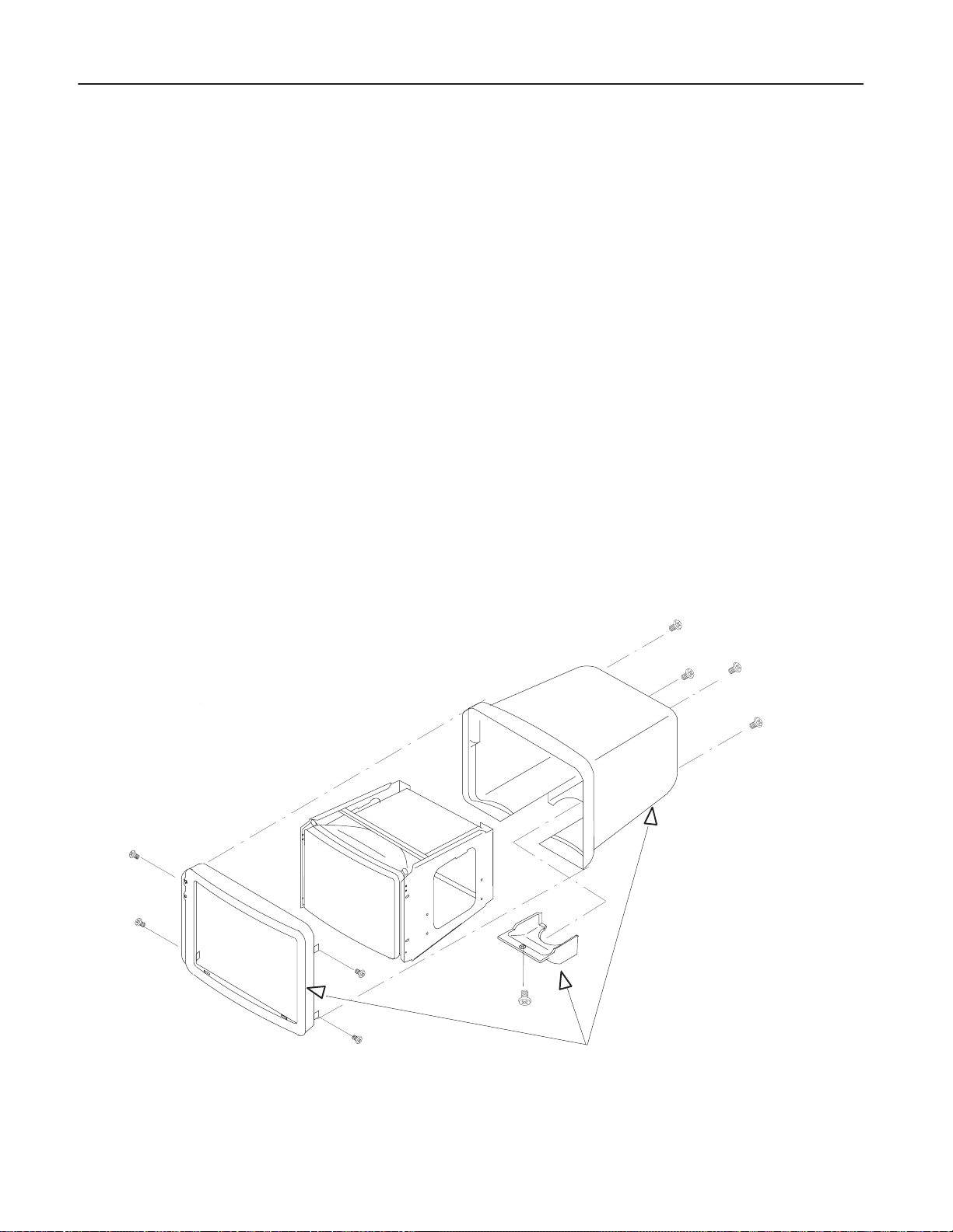
GE MEDICAL SYSTEMS
REV 4
6–2–4 Monitor Cover Set (FRU No. 103)
Time Required
4 Minutes
Tool Required
Screwdriver
Procedure
Refer to ILLUSTRATION 6–10.
LOGIQ α200 SERVICE MANUAL
2138853
1. Turn OFF the system.
2. Lift and set the Monitor to the highest position by pushing down the Up/down Release Button located on the
Swing Arm Assy .
3. Unscrew one screws (1) and remove the Monitor Bottom Cover.
4. Unscrew four screws (2 – 5) and remove the Monitor Rear Cover.
5. Unscrew four screws (6 – 9) and remove the Monitor Front Cover.
Monitor Rear Cover
8
9
2
4
Monitor Bottom Cover
3
5
Monitor Front Cover
6
1
103 Monitor Cover Set
7
MONITOR COVER ASSY DISASSEMBLY
ILLUSTRATION 6–10
6–28 RENEW AL PARTS
Page 96

GE MEDICAL SYSTEMS
REV 4
6–2–5 Tilt Assy(FRU No. 104)
Time Required
8 Minutes
Tool Required
Screwdriver
Procedure
Refer to ILLUSTRATION 6–11.
LOGIQ α200 SERVICE MANUAL
1. Turn OFF the system.
2. Remove the Monitor Assy (FRU No. 100) from the Swing Arm Assy. Refer to 6–2–1.
3. Remove the Monitor Rear Cover. Refer to 6–2–4.
4. Unscrew four screws (1 – 4).
2138853
5. Remove the Tilt Assy.
104 Tilt Assy
3
4
1
2
TILT ASSY DISASSEMBLY
ILLUSTRATION 6–11
6–29 RENEW AL PARTS
Page 97

GE MEDICAL SYSTEMS
REV 4
6–2–6 Monitor Space Plate (FRU No. 105)
Time Required
6 Minutes
Tool Required
Screwdriver
Procedure
Refer to ILLUSTRATION 6–12.
LOGIQ α200 SERVICE MANUAL
1. Turn OFF the system.
2. Remove the Monitor Assy (FRU No. 100) from the Swing Arm Assy. Refer to 6–2–1.
3. Remove the Monitor Space Plate.
2138853
105 Monitor Space Plate
MONITOR SPACE PLATE DISASSEMBLY
ILLUSTRATION 6–12
6–30 RENEW AL PARTS
Page 98

GE MEDICAL SYSTEMS
REV 4
6–2–7 Probe Holder (FRU No. 201)
Time Required
2 Minutes
Tool Required
Not necessary
Procedure
Refer to ILLUSTRATION 6–13.
1. Turn OFF the system.
2. Pull the PG latch located at bottom of the Probe Holder.
3. Pull the Probe Holder out as shown in ILLUSTRATION 6–13.
LOGIQ α200 SERVICE MANUAL
2138853
PG latch
PROBE HOLDER DISASSEMBLY
ILLUSTRATION 6–13
201 Probe Holder
6–31 RENEW AL PARTS
Page 99

GE MEDICAL SYSTEMS
REV 4
6–2–8 Holder Bracket Assy (FRU No. 202)
Time Required
3 Minutes
Tool Required
Screwdriver
Procedure
Refer to ILLUSTRATION 6–14.
1. Turn OFF the system.
2. Remove the Probe Holder (FRU No. 201). Refer to 6–2–7.
3. Unscrew three screws (1 – 3).
4. Remove the Holder Bracket Assy.
LOGIQ α200 SERVICE MANUAL
2138853
202 Holder Bracket Assy
1
HOLDER BRACKET ASSY DISASSEMBLY
ILLUSTRATION 6–14
3
2
6–32 RENEW AL PARTS
Page 100

GE MEDICAL SYSTEMS
REV 4
6–2–9 Keyboard Cover Set (FRU No. 203)
Time Required
11 Minutes
Tool Required
Screwdriver
Procedure
Refer to ILLUSTRATION 6–15.
1. Turn OFF the system.
2. Remove the Probe Holder (FRU No. 201). Refer to 6–2–7.
3. Remove the Holder Bracket Assy (FRU No.202) Refer to 6–2–8.
4. Unscrew two ground screws (1 and 2) on the front bottom of Keyboard .
LOGIQ α200 SERVICE MANUAL
2138853
5. Unscrew three screws on the PCB that hold Ground Terminal wire and remove three clamps.
6. Unscrew two screws ( ) and remove two Ground Terminals.
7. Disconnect the connector and cut the tie wraps off.
8. Remove the KB Cover Top Assy with Keyboard Assy (FRU No. 204).
9. Unscrew eight screws (3 – 10) and remove the KB Cover Top Assy.
10. Unscrew nine screws (11 – 19) and remove the KB Cover Bottom.
6–34 RENEW AL PARTS
 Loading...