

Page 1

LOGIQ 500
Quick Start Guide 2276613–100
A Training in Partnership Program
TM
Ti
P
Page 2

This page left blank intentionally .
Page 3

%$ #
"$
&#
% $"$ %
!"$ %$$
Page 4

Regulatory Requirement
This product complies with regulatory requirements of the following European Directive 93/42/EEC concerning medical
devices
This Quick Start Guide is a reference for LOGIQ 500 PRO Series. It applies to all versions of 6.0 software for the
LOGIQ 500
.
GE Medical Systems
GE Medical Systems: Telex 3797371
P.O. Box 414, Milwaukee, Wisconsin 53201 U.S.A.
(Asia, Pacific, Latin America, North America)
GE Ultrascall: Tel: +49 (0) 212 28 02 208
Deutschland GmbH & Co KG
Beethovenstraße 239, Postfach 1 1 05 60, D–42655 Solingen
GERMANY
Page 5

REV
0 July 10, 2000 Initial Release
DATE REASON FOR CHANGE
TiP Cover Page N/A
Title Page 0
LOGIQ 500 Quick Start Guide
2276613–100 Rev . 0
Revision History A and B 0
Quick Start 1 thru Quick Start 40 0
Revision History A
Page 6

Revision History B
LOGIQ 500 Quick Start Guide
2276613–100 Rev . 0
Page 7

Introduction
The Quick Start Guide (TRANSLATED) provides a step-by-step description of the basic features and
operation of the LOGIQ 500. It is intended to be used in conjunction with the Basic User Manual in order to
provide the information necessary to operate the system safely .
The Quick Start Guide takes the user from system familiarization through power on, patient data entry , exam
category/preset selection, scan modes/adjustments, basic measurements, report pages, recording images
and power off.
The LOGIQ 500 manuals are written for users who are familiar with basic ultrasound principals and techniques. They do
not include sonography training or clinical procedures.
Prescription Device (for USA only)
CAUTION: United States law restricts this device to sale or use by or on the order of a physician.
LOGIQ 500 Quick Start Guide
2276613–100 Rev . 0
Quick Start 1
Page 8
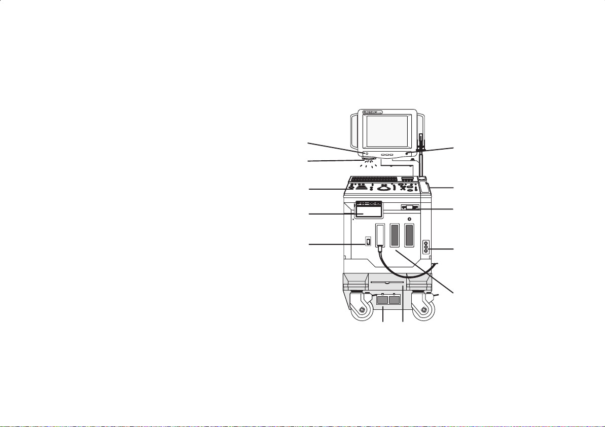
Front View
The following are major features of the LOGIQ 500 system console. Most features come with the standard configuration,
while other features are options to the standard console.
1. VCR Microphone
2. Probe Holder
3. MOD Drive
4. Physio Panel *
5. Probe Connectors (3 ports)
6. Air Filter
7. Power Supply Filter
8. On/Off Switch
9. B/W Page Printer *
10. Keyboard
11. Keyboard Task Light
12. Task Light Switch
* = optional feature or accessory
12
11
10
1
2
9
8
3
4
5
76
Quick Start 2
LOGIQ 500 Quick Start Guide
2276613–100 Rev . 0
Page 9
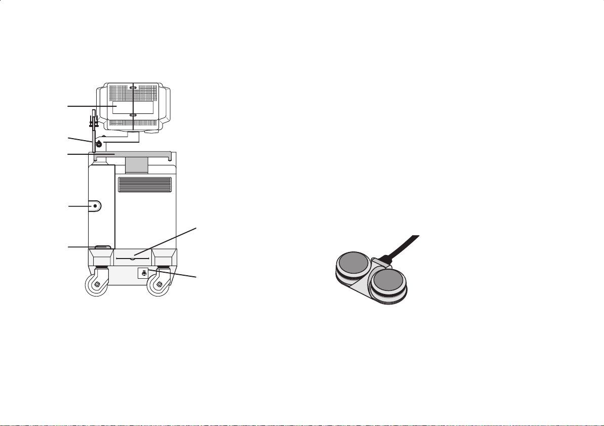
Back View
7
6
5
4
3
1. Circuit Breaker
2. Air Filter
3. Cable Access
4. Peripheral Cable Access Door
5. Handle for Pushing
6. Monitor Arm Swivel Lock
7. Color Monitor
2
Optional Freeze/Record Foot Switch
Freeze
ON
ON
OFF10
1
Record
LOGIQ 500 Quick Start Guide
2276613–100 Rev . 0
Quick Start 3
Page 10
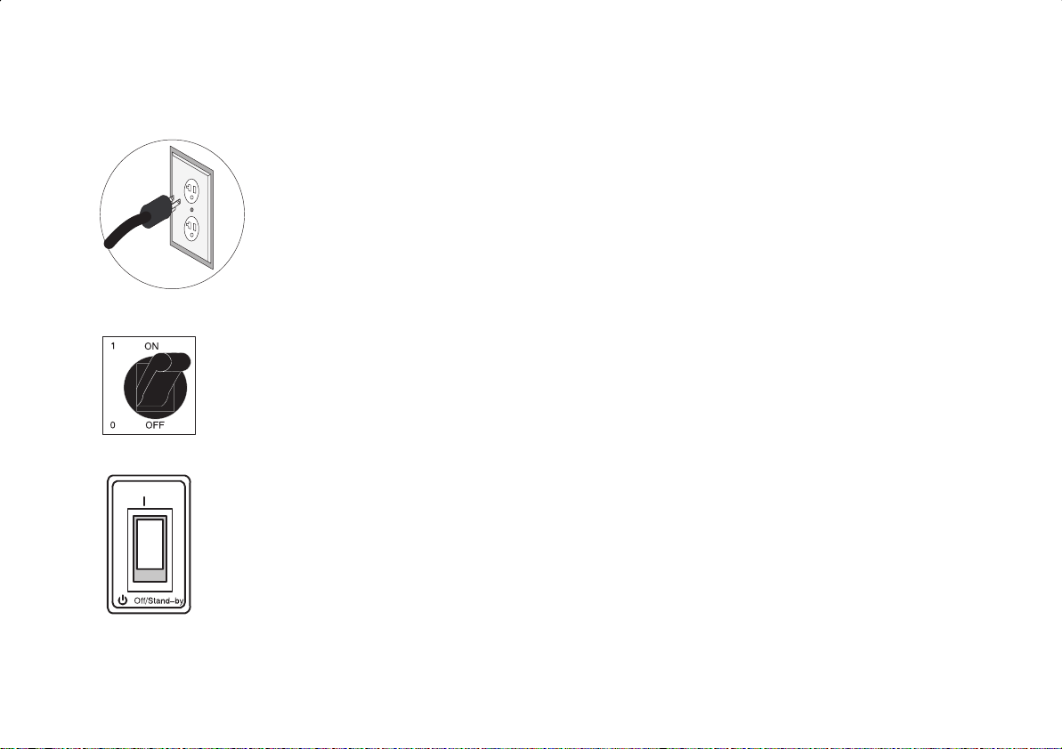
Power On
On
To connect the system to the electrical supply:
S Ensure that the wall outlet is a minimum 20 amp dedicated circuit for 120 VAC (USA) or 7.5
amp dedicated circuit for 220–240 V AC (Europe).
S Make sure that the power switch is turned off.
S Unwrap the power cable. Make sure to allow sufficient slack in the cable so that the plug is
not pulled out of the wall if the system is moved slightly .
S Push the power plug securely into the wall outlet.
To power on the system, ensure that the Circuit Breaker, located on the back of the power
supply near the bottom of the unit, is turned on.
Press the Power On Power Off/Stand-by switch, located to the left of the probe connectors, to
the on position.
Quick Start 4
LOGIQt 500 Quick Start Guide
2276613–100 Rev . 0
Page 11
Power On (cont’d)
During power up, the screen display changes as the system runs its self diagnostics.
Start of
diagnostic
Version X.XX Version X.XX
LOGIQ 500 Quick Start Guide
2276613–100 Rev . 0
XXXXXXXXXXXXXX
End of
diagnostic
Version X.XX
Quick Start 5
Page 12
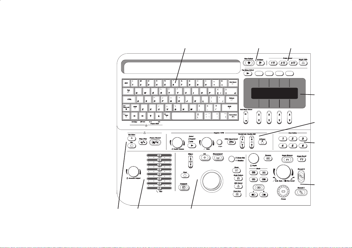
Control Panel Layout
Keyboard
Keyboard controls have been
arranged according to function
and usage. This helps
minimize operator movement
while scanning.
1. Alphanumeric Keys
2. New Patient
3. Probe Select
4. Soft Menu Controls
5. Doppler and CFM
6. User Define
7. Mode, Display and Record
8. Measurements/Annotations
9. TGC and Acoustic Output
10. VCR
123
4
5
↓
"yA
"yA
6
7
Quick Start 6
10
98
LOGIQt 500 Quick Start Guide
2276613–100 Rev . 0
Page 13
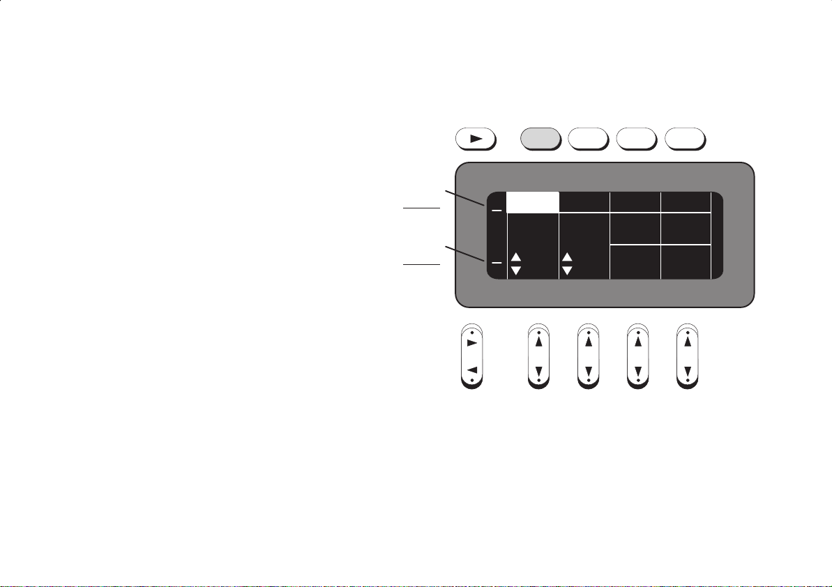
Soft Menu Control Panel
The Soft Menu Display has 8 Top Menu
selections (Mode, Preset, Set Up, ECG, Archive,
DICOM, AutoSeq and Cine) and 8 Sub Menu
selections (varies depending on choice of Top
Menu selection) available.
The Top Menu Select key cycles through the top
level menu page selections. The far left side top
menu is the default selection and its sub-menus
are automatically displayed.
The Sub-Menu Select rocker switch cycles to the
") or previous (A ) sub-menu page.
next (
The Sub-Menu rocker switches allow for the
increase/decrease of a parameter value or
enabling/disabling of a parameter.
TOP MENU
Current
Available
SUB-MENU
Current
Available
Sub-Menu Select
T op Menu Select
1
2
2
4
Preset ECG
Frame Imaging
Average
OFF
Freq
3 MHz
Set UpB
Image
Softner
Color
3D
Mode
LOGIQt 500 Quick Start Guide
2276613–100 Rev . 0
Quick Start 7
Page 14
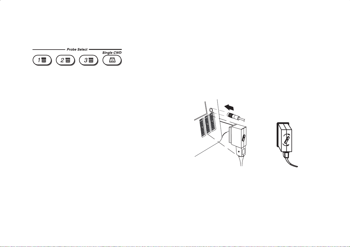
Probe Controls
A probe is activated by pressing the Probe Select key that corresponds to the
probe port to which the desired probe is connected. The Single CWD key is
used to activate the dedicated continuous wave Doppler (CWD) probe. The
active probe key will be brightly lit.
Probe Ports
All imaging probes can be plugged into any of the three
probe ports.
The CWD probes can be plugged into the Single CWD
port which is located above Probe Port Position 3.
NOTE: Ensure that the probe port is
.
deactivated and the image is frozen before
disconnecting the probe.
lock
unlock
Quick Start 8
LOGIQt 500 Quick Start Guide
2276613–100 Rev . 0
Page 15

Starting an Exam
Patient Entry Menu
Press the New Patient key at the beginning
of each study to reset the system and enter
new patient data. When the New Patient key
is pressed, the Patient Entry menu appears.
Ensure that the Blue Shift key is not active.
Use the Trackball to move the highlight cursor to the Exam
Category Selection line. Enter the desired exam number and fill in
the appropriate patient data.
Highlight EXIT and press Return or press New Patient again when
the patient entry menu data has been completed.
The system takes a few seconds to load new exam category
parameters and calibrate the attached transducers before entering
the scan mode.
LOGIQ 500 Quick Start Guide
2276613–100 Rev . 0
Quick Start 9
Page 16

Application Presets
Select the exam category application preset, that best
describes the desired study to be performed, from the
factory default preset selections displayed on the Soft
Menu.
General
OB
Fetal
Heart
Select the desired probe.
Quick Start 10
Diff
NewbornTech
LOGIQ 500 Quick Start Guide
2276613–100 Rev . 0
Page 17

Scan Mode Controls
Select the desired display mode or combination of display modes (B-Mode, Pulsed Doppler, Color
low Mode, M-Mode or Continuous Wave Doppler Mode).
F
CWD Mode is available for sector probe only .
If the dual display mode (split screen) is desired, the L and R keys activate the Left or Right
displayed image.
Scan the desired anatomy . Change modes as desired. Use the mode controls to adjust the image
as necessary.
LOGIQ 500 Quick Start Guide
2276613–100 Rev . 0
Quick Start 11
Page 18

B-Mode Controls
There are four Soft-Menu pages for B-Mode imaging adjustments.
Dynamic Range—Controls how echo intensities are converted to
shades of gray , thereby creating a range of gray scale that can be
adjusted.
Gray Map—Determines how the echo intensity levels received are
presented as shades of gray .
Focus Number—Changes the number of focal zones so that the beam
can be tightened or expanded for a specific area.
ATO Create—Automatic Tissue Optimization optimizes the image based
upon a specified Region of Interest (ROI) or anatomy within the display .
ATO On/Off—Highlighted when the ATO map is active on the image;
toggle on and off to display that same ATO map again.
Frame Average—Averages previous frames of image data with the
current frame.
Imaging Freq—Allows more echoes to pass through.
Image Softner—Adjust for the amount of smoothing applied.
Color—Allows for enabling B-Mode image colorization.
3D Mode—Allows for 3D Mode option activation.
Dynamic
Range
48
Frame
Average
OFF 3 MHz
PresetB
Gray
Map
Set Up ECG
Focus
Number
B–2 2
ATO
Create
ATO
On/Off
PresetB Set Up ECG
Imaging
Freq
Image
Softner
Color
3D
Mode
Quick Start 12
LOGIQ 500 Quick Start Guide
2276613–100 Rev . 0
Page 19

B-Mode Controls (cont’d)
Focus
Positn
Biopsy
Zone
PresetB Set Up ECG
Color
Tag
SGL
PresetB
Rotatn
0DEG 40 MID
Set Up ECG
RejectnImage
Tag
Positn
Edge
Enhance
Focus Positn—Changes the depth at which the selected number of
focal zones are optimized.
Color Tag—Enables the colorization of a specific gray scale level range.
T ag Position—Allows for the movement of the specified color tag range
throughout the gray scale displayed.
Biopsy Zone—Enables the electronic guidezone(s) available for the
active probe.
Image Rotate—Rotates the single real-time or zoomed B-Mode image in
90° increments.
Rejectn—Allows for the elimination of low level echoes from the display.
B Edge Enhance—Brings out subtle tissue differences and boundaries
by enhancing the gray scale differences corresponding to the edges of
structures.
LOGIQ 500 Quick Start Guide
2276613–100 Rev . 0
Quick Start 13
Page 20

B-Mode Controls (cont’d)
The keyboard controls that effect B-Mode are as follows:
98
↓
1 64 53 7
2
"yA
"yA
1. Acoustic Output—Allows for varying the power output of the transmitted sound wave.
2. TGC—Balances the image so brightness is consistent throughout the image. Move the slide pot to the right to
increase or the left to decrease.
3. Scan Area—Used to assign trackball control to adjust size/position B-Mode sector display , CFM window, and
horizontal size/position of the real-time zoom window.
LOGIQt 500 Quick Start Guide
Quick Start 14
2276613–100 Rev . 0
Page 21

B-Mode Controls (cont’d)
4. Depth—To reduce depth (look at a shallower image), turn the Depth rotary encoder clockwise. To increase depth
(look at a deeper image), turn the Depth rotary encoder counterclockwise.
5. Display Format (Dual)— Left/Right split screen display.
6. Reverse—The GE logo at the top of the sector wedge corresponds to the orientation mark on the probe body. When
Reverse is active, the image flips and the GE logo switches to correspond to the probe mark.
7. B/M Gain—Controls the gain of the displayed echoes. To increase/decrease, turn the control clockwise/
counterclockwise.
8. Angle—Controls the gain in B/M and CFM-B/M Mode.
9. Focus Position—While in B-Mode only , Baseline Shift can be used to change Focus Position.
LOGIQ 500 Quick Start Guide
2276613–100 Rev . 0
Quick Start 15
Page 22

B-Mode Controls (cont’d)
B-Mode Optimization
Adjustments for... Do the Following... Adjustments for... Do the Following...
Image too grainy
Image too noisy
Cystic Imaging
1. Increase Dynamic Range.
2. Increase Frame Average.
3. Decrease Edge Enhance.
4. Change Gray Map.
1. Decrease B/M GAIN.
2. Decrease Dynamic Range.
3. Increase Frame Average.
4. Increase Edge Enhance.
1. Decrease the B/M GAIN.
2. Decrease Dynamic Range.
3. Use SCAN AREA SIZE to reduce
image width.
4. Change Focus Number to increase
number of focal zones.
5. Optimize focal zone placement.
Image too soft
Improve Uniformity
Technically Difficult
Patients
1. Decrease Dynamic Range.
2. Increase Edge Enhance.
3. Decrease Frame Average.
4. Change Gray Map.
1. Increase the number of focal zones.
2. Decrease SCAN AREA SIZE.
3. Adjust TGC to compensate for
attenuation.
1. Select the proper probe or change
Imaging Freq. for the exam (larger
patient, lower frequency).
2. Increase ACOUSTIC OUTPUT, if
necessary.
3. Maintain a lower Dynamic Range
(45 to 48).
4. Decrease SCAN AREA SIZE for
faster frame rates.
Quick Start 16
LOGIQ 500 Quick Start Guide
2276613–100 Rev . 0
Page 23

Color Flow Mode (CFM) Controls
There are four Soft-Menu pages for Color Flow Mode imaging adjustments.
CFM Map—Allows for the selection of how Doppler velocities are
mapped as color over the gray scale.
Slant Scan—Used to control the position of the CFM window for linear
probes only .
Diag Mode—Allows for the selection of the best color flow display
format.
MTI Filter—Filters out low flow velocity color.
Frame Average—Averages color information from previous frames with
the current frame.
Penet.—Penetration can be increased by lowering the operating
frequency of the active probe.
High Resoltn—Provides a quick way to maximize resolution for the
CFM display.
Display Thrshld—Gray scale level at which the overlay of color
information stops.
Capture—Displays the highest mean velocity (average velocity)
detected over a specific time interval.
CFM
Map
VT–1
Average
LOW
PresetCFM
Slant
Scan
PresetCFM
Penet.Frame
High
Resoltn
Set Up ECG
Diag
Mode
0 Map LOW
Set Up ECG
Thrshld
MTI
Filter
CaptureDisplay
53 0.5
LOGIQ 500 Quick Start Guide
2276613–100 Rev . 0
Quick Start 17
Page 24

Color Flow Mode (CFM) Controls (cont’d)
Packet
Size
MID
OFF
PresetCFM
Spatial
Filter
PresetCFM
Noise
Blanker
Set Up ECG
W.E.
Cancel
Color
OFF
Tag
Set Up ECG
Persist
ence
OFF
OFF
Positn
MR-FlowACE
Mode
Tag
3D
Packet Size—Controls the number of samples gathered for a single
color flow vector.
Spatial Filter—Smooths color information so that it is less grainy .
Averages the color information out over time.
W. E. Cancel—Eliminates the low velocity echoes caused by the motion
of vessel walls.
Color Tag—Allows for the assignment of a single color to a range of
velocities.
T ag Positn—Allows for the movement of the specified color tag range
throughout the gray scale displayed.
ACE—Reduces “color artifact noise”.
Noise Blanker—Reduces the random noise generated due to the
increase in Color Gain.
Persistence—Retains the largest pixel color value until a larger value is
detected or preset time has elapsed.
MR-Flow—Image enhancement option.
3D Mode—Allows for 3D Mode option activation.
Quick Start 18
LOGIQ 500 Quick Start Guide
2276613–100 Rev . 0
Page 25

Color Flow Mode (CFM) Controls (cont’d)
Acoustic output affects the transmit power for both B-Mode and CFM signals.
TGC and B/M Gain function only on the B-Mode image displayed.
The Dual Format keys work the same as in dual B-Mode, but both B-Mode and CFM are displayed on the left and right
sides of the screen.
The keyboard controls that effect CFM are as follows:
1. Color Doppler Gain—Adjusted overall
received echo gain for CFM. To
↓
increase/decrease, turn the control
clockwise/counterclockwise.
2. CFM/Spectrum Invert—Inverts Color
Flow Map assignments.
3. Velocity Scale—Adjusts velocity scale to
accommodate faster/slower blood flow
velocities. To increase/decrease, press
the top/bottom of the Velocity Scale
rocker switch.
4. Baseline Shift—Minimize aliasing by assigning more of the overall displayed velocity scale to forward or reverse flow.
To shift the baseline up/down, press the top/bottom of the Baseline Shift rocker switch.
5. Color Flow Window Size (Scan Area)—Used to assign trackball control to adjust size/position of the CFM window.
1
234
"yA
"yA
5
LOGIQt 500 Quick Start Guide
2276613–100 Rev . 0
Quick Start 19
Page 26

Color Flow Mode (CFM) Controls (cont’d)
Color Flow Mode Optimization
Adjustments for... Do the Following... Adjustments for... Do the Following...
Decrease Motion
Artifact
Improve Sensitivity
Decrease Color Flow
Bleeding
1. Increase the VELOCITY SCALE.
2. Increase W.E. Cancel.
1. Increase GAIN.
2. Decrease VELOCITY SCALE.
3. Increase ACOUSTIC OUTPUT.
4. Switch Penet. on and High Resoltn
on.
5. Decrease W.E. Cancel.
6. Increase Frame Average (this
allows gain to increase).
7. Increase Packet Size.
8. Reduce SCAN AREA SIZE to
smallest size reasonable.
9. Optimize focal zone position.
1. Decrease GAIN.
2. increase VELOCITY SCALE.
3. Decrease Display Thrshld.
Eliminate Aliasing
Improve Frame
Rate/Flow Dynamics
1. Increase VELOCITY SCALE.
2. Lower BASELINE SHIFT.
1. Decrease color window using
SCAN AREA SIZE width.
2. Exit COLOR FLOW to reduce
B-Mode image width (use SCAN
AREA SIZE).
3. Decrease DEPTH.
4. Increase VELOCITY SCALE (if
flow state allows it).
5. Decrease Frame Average.
Quick Start 20
LOGIQ 500 Quick Start Guide
2276613–100 Rev . 0
Page 27

Doppler Controls
There are four Soft-Menu pages for Pulsed Wave Doppler (PWD) imaging adjustments and for Continuous W ave Doppler
(CWD) imaging adjustments.
Automatic Spectral Optimization (ASO) Option—Optimizes the
Doppler spectral trace.
Auto Angle—Optimizes the angle correction automatically .
Slant Scan—Controls the position of the Doppler cursor for linear probes
only .
Wall Filter—Removes the low level, low frequency Doppler signal
caused by movement of the vessel walls.
S. V. Length—Changes the size of the sample volume gate length. Not
available in the CWD Soft-Menu.
Sweep Speed—Changes the speed at which the timeline updates
across the display.
Penet.—Penetration can be increased by lowering the operating
frequency of the active probe. Not available in the CWD Soft-Menu.
Color—Allows for enabling PWD or CWD Mode image colorization.
Color Tag—Enables the colorization of a specific gray scale level range.
T ag Positn —Allows for the movement of the specified color tag range
throughout the gray scale displayed.
ASO
Auto
Angle
Speed
MID
PresetPWD
Slant
Scan
PresetPWD
Set Up ECG
Wall
Filter
0 20.0 5
Set Up ECG
ColorPenet.Sweep
Color
Tag
S.V.
Length
Tag
Positn
LOGIQ 500 Quick Start Guide
2276613–100 Rev . 0
Quick Start 21
Page 28

Doppler Controls (cont’d)
Realtim
Trace
PresetPWD
RejectnHPRF
PresetPWD
Calc
Dir.
Compo
Set Up ECG
CFM/PWD
Ratio
40
1/2
Set Up ECG
Trace
Method
PEAKOFF
CFM
Shrink
Dynamic
Range
HPRF—Allows the operator to enable or disable the High Pulse
Repetition Frequency function while in Doppler Mode. Not available in
the CWD Soft-Menu.
Rejectn—Allows for the elimination of low level echoes from the display.
CFM/PWD Ratio—Used to set the velocity ratio between PWD and
CFM. Active in triplex mode. Not available in the CWD Soft-Menu.
CFM Shrink—Reduces the CFM window to specified size. Not available
in the CWD Soft-Menu.
Realtim Trace—Automatically traces in real-time.
Calc Dir.—Choose which part of the Doppler Trace is used for automatic
measurements/calculations.
Trace Method—Choose the method used to trace the Doppler
waveform in real-time (Peak, Floor, Mean or Mode).
30
Dynamic Range—Controls how echo intensities are converted to
shades of gray , thereby creating a range of gray scale that can be
adjusted.
Quick Start 22
LOGIQ 500 Quick Start Guide
2276613–100 Rev . 0
Page 29

Doppler Controls (cont’d)
Several controls affect the B-Mode portion of the display and not the echoes in the Doppler spectrum. These are TGC,
Depth, B/M Gain, Scan Area and Reverse keys. See
Quick Start 12
The keyboard controls that affect Doppler are as follows:
1. M/D Cursor—Assigns trackball control to the Doppler cursor.
2. Audio Volume—Used to adjust Doppler audio volume output. To
increase/decrease, turn the control clockwise/counterclockwise.
3. Doppler Spectral Gain—Adjusts overall received echo gain for
Doppler. To increase/decrease, turn the control clockwise/
counterclockwise.
4. Theta Angle Correction—Adjusts angle correction for flow velocity
calculation. To adjust the angle clockwise/counterclockwise relative
to the probe face, turn the control clockwise/counterclockwise.
5. CFM/Spectrum Invert—Inverts Doppler spectrum assignments.
6. Velocity Scale—Adjusts velocity scale to accommodate faster/slower blood flow velocities. To increase/decrease,
press the top/bottom of the Velocity Scale rocker switch.
7. Baseline Shift—Minimize aliasing by assigning more of the overall displayed velocity scale to forward or reverse flow.
To shift the baseline up/down, press the top/bottom of the Baseline Shift rocker switch.
8. B Pause—Freezes the B-Mode image while keeping the Doppler spectrum display active. Press to view CW Doppler.
for comments on these controls.
2 3 4 5678
"yA
1
LOGIQt 500 Quick Start Guide
2276613–100 Rev . 0
Quick Start 23
Page 30

Doppler Controls (cont’d)
Doppler Mode Optimization
Adjustments for... Do the Following... Adjustments for... Do the Following...
Increase Sensitivity
Increase Spectral
Clarity
1. Increase GAIN.
2. Increase ACOUSTIC OUTPUT.
3. Decrease VELOCITY SCALE (if
flow state allows it).
4. Increase S.V. Length.
5. Use lower frequency probe or use
lower Doppler frequency on some
applications.
6. Activate B-PAUSE to freeze
B-Mode image.
Scan angle is critical to Doppler
sensitivity.
1. Activate B PAUSE to freeze
B-Mode image.
2. Increase ACOUSTIC OUTPUT.
3. Decrease S.V. Length.
4. Decrease GAIN.
5. Decrease Dynamic Range.
Improve Display
Aesthetics
1. Activate B PAUSE to freeze
B-Mode image.
2. Decrease GAIN.
3. Increase ACOUSTIC OUTPUT.
4. Use smaller sample volume size,
whenever possible.
5. Increase/decrease Dynamic
Range.
6. Adjust BASELINE SHIFT and
VELOCITY SCALE to adjust
spectral size.
7. Lower Doppler Sweep Speed.
Quick Start 24
LOGIQ 500 Quick Start Guide
2276613–100 Rev . 0
Page 31

M-Mode Controls
There are two Soft-Menu pages for M-Mode imaging adjustments.
Dynamic Range—Controls how echo intensities are converted to
shades of gray , thereby creating a range of gray scale that can be
adjusted.
Gray Map—Determines how the echo intensity levels received are
presented as shades of gray .
Rejectn—Allows for the elimination of low level echoes from the display.
Edge Enhance—Brings out subtle tissue differences and boundaries by
enhancing the gray scale differences corresponding to the edges of
structures.
Sweep Speed—Changes the speed at which the timeline updates
across the display.
Color—Allows for enabling M-Mode image colorization.
Color Tag—Enables the colorization of a specific gray scale level range.
T ag Positn —Allows for the movement of the specified color tag range
throughout the gray scale displayed.
Dynamic
Range
Speed
MID
48
PresetM
Map
PresetM
Set Up ECG
RejectnGray
M–2 40 MID
Set Up ECG
ColorSweep
Color
Tag
Edge
Enhance
Tag
Positn
LOGIQ 500 Quick Start Guide
2276613–100 Rev . 0
Quick Start 25
Page 32

M-Mode Controls (cont’d)
Since M-Mode is basically a single B-Mode scan vector displayed over time, basic controls that affect the B-Mode display
also affect the M-Mode display. See
Quick Start 12
TGC and Depth affect both the M-Mode and B-Mode displays.
If the scan area size is reduced and the position changed, the M-Mode cursor will follow the position change to stay within
the displayed scan area.
The Dual Format keys work the same as in dual B-Mode, but both B-Mode and M-Mode are displayed on the left and right
sides of the screen.
The keyboard controls that effect M-Mode are as follows:
1. B/M Gain—Controls the gain of the displayed timeline
echoes. To increase/decrease, turn the control clockwise/
counterclockwise.
2. M/D Cursor—Assigns trackball control to the M-Mode cursor.
3. Zoom—Enables real-time or freeze zoom function.
Adjustments for... Do the Following... Adjustments for... Do the Following...
Improve M-Mode
1. Increase/decrease B/M GAIN.
2. Increase Dynamic Range.
for comments on these controls.
M-Mode Optimization
Increase Size of Area
of Interest
"yA
13 2
1. Use M-Mode ZOOM.
Quick Start 26
LOGIQt 500 Quick Start Guide
2276613–100 Rev . 0
Page 33

Reviewing Cine Images
Press Freeze to stop image data acquisition.
When Freeze is activated, rotate the Cine Scroll control to display individual image frames which
were stored by the system.
NOTE: Cine frame number 0 is the most current image. The higher the Cine frame number, the
older the image.
The depth, dynamic range, and gain parameters displayed on the screen are valid for Cine frame
number zero only .
LOGIQ 500 Quick Start Guide
2276613–100 Rev . 0
Quick Start 27
Page 34

Image Annotation
Keyboard Annotation
The annotation keyboard is always active. Upon power up or starting a new patient, the underscore cursor appears in the
mode’s home position. Comments may be typed in at the non-blinking cursor.
Pressing the Comment key assigns the trackball function to controlling the cursor.
The Trackball and Keyboard Arrow keys are used to move the cursor to the desired position on the
image.
When the blinking cursor is in the desired position, comments may be typed in. Annotations are
entered in the type-over, not insert, mode. Be careful not to write over text when editing.
Quick Start 28
LOGIQ 500 Quick Start Guide
2276613–100 Rev . 0
Page 35

Special Keys—Symbols
Blue Shift: Some special annotation symbols can be used by activating the Blue Shift key. Those
?
/
keys have special symbols shown in blue on the keyboard.
Activating Blue Shift causes the arrow, female and male symbols to be printed on the screen during
the comment function when the keys shown are pressed.
The Blue Shift key acts as a lock function (similar to Caps Lock key). Press again to exit the Blue
Shift function.
Special Keys—Language-Specific Characters
Special language-specific characters, shown in red on the keyboard, can be used by activating the Red Shift key . Refer to
Annotating an Image section of Chapter 6 (Scanning and Display Functions)
the
on activating these characters.
of the Basic User Manual for more details
LOGIQt 500 Quick Start Guide
2276613–100 Rev . 0
Quick Start 29
Page 36

Body Patterns
↑
↓
Body patterns are a simple graphic of a portion of the anatomy that is frequently scanned. Press the
Body Pattern key to activate Body Patterns.
A body pattern, generally displayed in the lower left corner of the screen,
appears.
Cycle through the body patterns by pressing the top/bottom of the Ellipse
rocker switch.
A Probe Orientation Marker is used to illustrate the probe position. This
marker can be placed with the Trackball and rotated with the Zoom
Size/Rotation control.
Probe
Orientation
Marker
Press Set to complete the body pattern selection.
Quick Start 30
LOGIQ 500 Quick Start Guide
2276613–100 Rev . 0
Page 37

Performing Basic Measurements
K
d
Basic measurements are displayed on the monitor and not automatically entered into a report page unless a specific
measurement/calculation is selected from the sub-menu. The specific measurement/calculation can be chosen before or
after the basic measurement has been performed.
Scan the desired anatomy and press Freeze.
MODE
ey Presse
(while frozen)
Once Distance
Twice Trace/Circle TAMAX/TAMIN/
Three Times Gray Scale Echo Level 2 Velocities
Four Times Arrow Mark * Time Interval Arrow Mark * Gray Scale Echo Level
Five Times Arrow Mark * Arrow Mark *
B Spectral Doppler
M (with B) CFM (with B)
(with B)
Ellipse/Circle
Peak Velocity Tissue Depth
TAMEAN/TAMODE
Slope/Time
Interval
(Distance)
Time Interval Trace/Circle
Depth Difference
Slope/Time Interval
* Assuming the “Arrow Mark Display” preset is set to on.
Distance
Ellipse/Circle
Point Velocity
LOGIQ 500 Quick Start Guide
2276613–100 Rev . 0
Quick Start 31
Page 38

Distance (B-Mode) and Tissue Depth (M-Mode)
Perform a distance measurement for calculations such as BPD, FL, CRL, LVIDd and LVPWs.
Press Measurement once.
Use the Trackball to move the “” cursor to the measurement start point. Press Set to fix the
measurement start point cursor and to display a second cursor.
Use the Trackball to move the second “” cursor to the measurement end point. Press Set to
complete the measurement and fix the Distance value displayed on the bottom part of the screen.
Quick Start 32
LOGIQ 500 Quick Start Guide
2276613–100 Rev . 0
Page 39

Circumference/Area - Ellipse (B-Mode)
Perform a circumference/area using the ellipse method for calculations such as AC, HC, L VAMd, LVAd and Volume.
Press Measurement once.
Use the Trackball to move the “” cursor to either end of the major axis of the area to measure.
Press Set to fix the start point cursor.
Use the Trackball to move the second cursor to the major axis measurement end point. Press the
↑
↓
top of the Ellipse rocker switch. An ellipse having an initial circle shape appears.
Use the Trackball to position the ellipse, as necessary, and to size the measured axis. Press Set to
complete the ellipse measurement and record the circumference and area.
LOGIQ 500 Quick Start Guide
2276613–100 Rev . 0
Quick Start 33
Page 40

Circumference/Area - Ellipse (B-Mode) (continued)
Prior to completing the ellipse measurement, the following keys can be used to fine tune the measurement.
Press the Measurement key to toggle the activation of the measurement cursors.
Press the top of the Ellipse rocker switch to increase the size of the minor axis.
↑
↓
Press the bottom of the Ellipse rocker switch to decrease the size of the minor axis.
Press Clear once to erase the ellipse and the current data measured. The original cursor is
displayed to restart the measurement. Pressing Clear a second time exits the measurement
function without completing the measurement.
Press Set to complete the ellipse measurement.
Quick Start 34
LOGIQ 500 Quick Start Guide
2276613–100 Rev . 0
Page 41

Circumference/Area - Trace (B-Mode)
Perform a circumference/area using the trace method for calculations such as AC, HC, L VAMd, LVAd and % Stenosis.
Press Measurement twice to display a dot “” cursor on the screen.
Use the Trackball to move the dot “” cursor to the measurement start point. Press Set to change
the dot “” cursor to a “” cursor.
Use the Trackball to trace the measurement area. Press Set to fix the Circumference value
displayed on the bottom of the screen and calculate the area.
NOTE: When using the trace method, the Zoom Size/Rotation knob can be used to edit the trace
line. Turn it clockwise or counterclockwise to erase the line (bit by bit) back from its current point.
The erase function is limited to a small portion of the most recent trace.
Peak Velocity (Doppler)
Perform a peak velocity measurement for calculations such as RI, PI, S/D Ratio, Max PG and Mean PG.
Press Measurement. The “” cursor with a vertical dotted line appears.
Use the Trackball to move the cursor to the desired point of measurement in the Doppler Spectrum.
Press Set to fix the velocity cursor. The velocity measurement in m/s or cm/s will be displayed at
the bottom of the screen.
NOTE: The “Display MaxPG with Velocity” preset, located on Preset Program page 4, allows
MaxPG to be displayed with the Peak Velocity measurement.
LOGIQ 500 Quick Start Guide
2276613–100 Rev . 0
Quick Start 35
Page 42

Time Interval (M-Mode and Doppler)
Perform a time interval measurement for calculations such as HR, PHT and ET.
Press Measurement twice in M-Mode and four times in Doppler. A “” cursor with vertical dotted
lines appears when the cursor is in the M-Mode timeline/Doppler spectrum.
Use the Trackball to move the cursor to the measurement start point. Press Set to fix the first
cursor.
Use the Trackball to move the second cursor to the measurement end point. Press Set to complete
the measurement.
The time interval between the two cursors is displayed.
Erasing Measurements
Pressing Clear or unfreezing the image erases all measurements and calculations on the display.
Measurements and calculations, however, remain on the report pages.
Pressing New Patient erases all measurements and calculations on the display and clears the
report pages.
Rotating the Cine Scroll control erases measurements.
Adding a new measurement that exceeds the maximum number of allowable measurements erases
the first or oldest measurement.
Quick Start 36
LOGIQ 500 Quick Start Guide
2276613–100 Rev . 0
Page 43

Report Pages
Specific diagnostic exam
categories have report
pages to summarize
measurements and
calculations performed
while in that exam
category. These
categories are Obstetrics,
Gynecology, Cardiology
and V ascular.
A report page can be
displayed by pressing
Measurement and
selecting it from the
measurement sub-menu.
LOGIQ 500 Quick Start Guide
2276613–100 Rev . 0
Quick Start 37
Page 44

Recording Images
Image Memory
The F1 and F2 keys can be assigned to the Image Memory and Image Recall functions. The F1
and F2 key presets are found on Set Up/System Parameters page 3.
Press the F1 or F2 key (Image Memory selection) to temporarily store the maximum of 8 images in
system memory.
The images are erased when the New Patient key is pressed or power is turned off.
Press the F1 or F2 key (Image Recall selection) to display the last image stored in system memory.
Press Top Menu Select to display a sub-menu of all images stored in system memory. Use the
appropriate Sub-Menu rocker switch to select the desired image.
After recall, comments, measurements and body patterns can be added to the image. The image is
then available for printing or archival.
Printing
Use the Record 1 or Record 2 keys to print the image/report page on a black/white or color (option)
video page printer.
The function of these keys was established during installation.
Quick Start 38
LOGIQ 500 Quick Start Guide
2276613–100 Rev . 0
Page 45

VCR Functions
Use with the Sony SVO–9500MD VCR. If a different model VCR is installed
↓
"
J
/
/F
on the system, use the controls on the VCR.
Probe Cleaning/Disinfection
Probes should be cleaned and disinfected after each use. The Probe Immersion Levels are provided with the probe but
are also pictured in the
NOTE: Special instructions for the E721 and ERB7 probes are found in the Probes chapter of the User
.
Manual.
Probes
chapter of the User Manual.
LOGIQt 500 Quick Start Guide
2276613–100 Rev . 0
Quick Start 39
Page 46

Power Off
On
To power down the system, press down on the Power On Power Off/Stand-by switch.
After turning the power off, the system takes a few seconds to update certain parameters to the
hard drive before the power is disconnected.
NOTE: During this time the message
“Do not pull Power Cable.”
“Do not turn off Breaker.”
flashes on the monitor. The message “WARNING: NOW START THE POWER OFF
PROCESS.” is also displayed at the bottom of the screen.
While the system is running during this power down process, do NOT turn off the
circuit breaker in the back of the machine and do NOT unplug the system from the
wall outlet.
If the system has not turned off five minutes after pressing the power switch off,
listen for hard drive activity. If there is no hard disk drive activity, the circuit
breaker on the bottom of the power supply can be used to turn off the system. Do
NOT turn off the circuit breaker while the hard disk is working.
Quick Start 40
LOGIQ 500 Quick Start Guide
2276613–100 Rev . 0
 Loading...