

Gast R2303A, R3305A-1, R3305A-13, R4P315A, R4310A-2 Operation & Maintenance Manual
...
STANDARD REGENAIR BLOWER
O
PERATION
& M
AINTENANCE
M
ANUAL
Thank you for purchasing this Gast product. It is manufactured to the highest standards
using quality materials. Please follow all recommended maintenance, operational
and safety instructions and you will receive years of trouble free service.
General information
This manual does not apply to:
• SDR Series blowers without motors
• Blowers powered with Explosion Proof Motors
PA RT NO. 70 - 6 000 F2 -2 00 (REV-J)
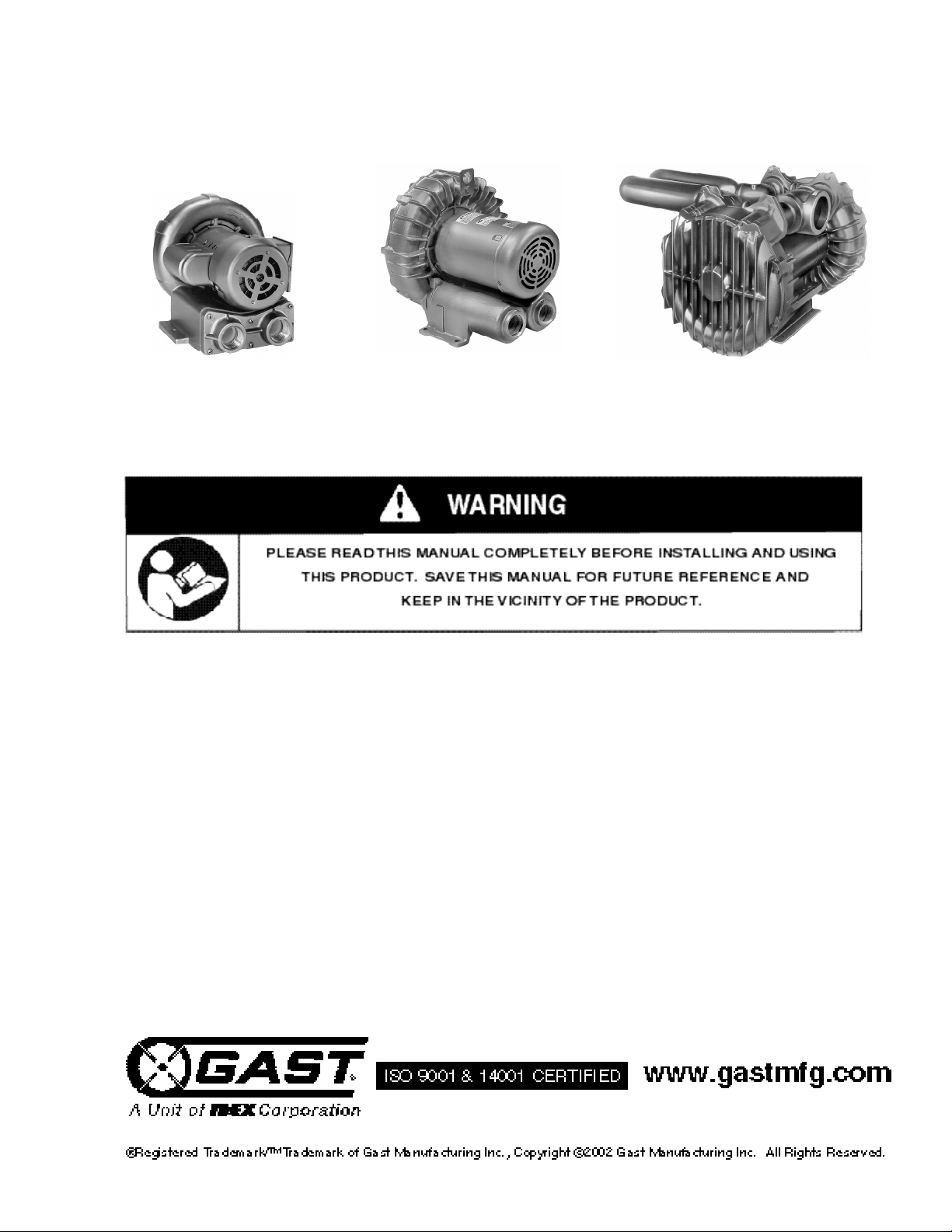
Model R1 Shown
Model R6P350A S h o w n
Model R7P S h o w n
Product Use Criteria:
• Pump only clean, dry air.
• Operate at -20ºF - 104ºF (-29ºC - 40ºC).
• Protect unit from dirt & moisture.
• Do not pump flammable or explosive gases or
use in an atmosphere that contains such gases.
• Protect all surrounding items from exhaust air. This
exhaust air can become very hot.
• Corrosive gases and particulate material will
damage unit. Water vapor, oil-based contaminants
or other liquids must be filtered out.
• The blower must be installed with the properly sized inlet and inline filters, gauges and
relief valves to protect the product from dirt and over-heating.
• Consult your Gast Distributor/Representative
before using at high altitudes.
Your safety and the safety of others
is extremely important.
We have provided many important safety messages
in this manual and on your product. Always read
and obey all safety messages.
This is the safety alert symbol. This symbol
alerts you to hazards that can kill or hurt you and
others. The safety alert symbol and the words
“DANGER” and “WARNING” will precede all safety
messages. These words mean:
You will be killed or seriously injured if you don’t
follow instructions.
You can be killed or seriously injured if you don’t
follow instructions.
All safety messages will identify the hazard, tell you
how to reduce the chance of injury, and tell you
what can happen if the safety instructions are not
followed.
Correct installation is your responsibility. Make sure
you have the proper installation conditions and that
installation clearances do not block air flow.
Blocking air flow over the product in any way can
cause the product to overheat.
The blower must be installed with the properly sized
inlet filter, gauge and relief valve to protect the
product from dirt and over-heating.
I N S TA L L A T I O N
Accessories
Install two vacuum gauges, one before and one after
filter, to monitor restriction through filters. As filters
become clogged, performance efficiency will be
reduced. Filters should be checked periodically and
replaced when necessary. See page 7 for installation.
Install a relief valve to avoid changes in pressure or
vacuum that can cause overloading of large blowers.
Install an intake filter with a relief valve to prevent
foreign material from entering blower if blower is used in
a vacuum application in a dirty environment. In
applications where there is high humidity or liquids
being used in the process, install a moisture separator.
See Recommended Accessories on pages 7-9 or
consult your Gast Distributor/Representative for
additional filter and accessories recommendations. Do
Not install check valves that close with a strong spring.
The recommended check valves (page 7) provide
minimal pressure drop, positive sealing and are
resistant to the high discharge temperatures of large
blowers.
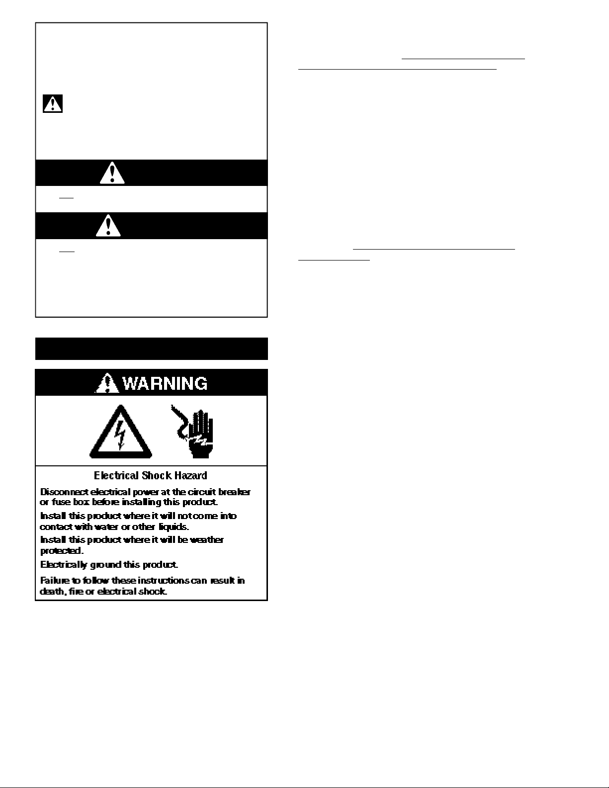
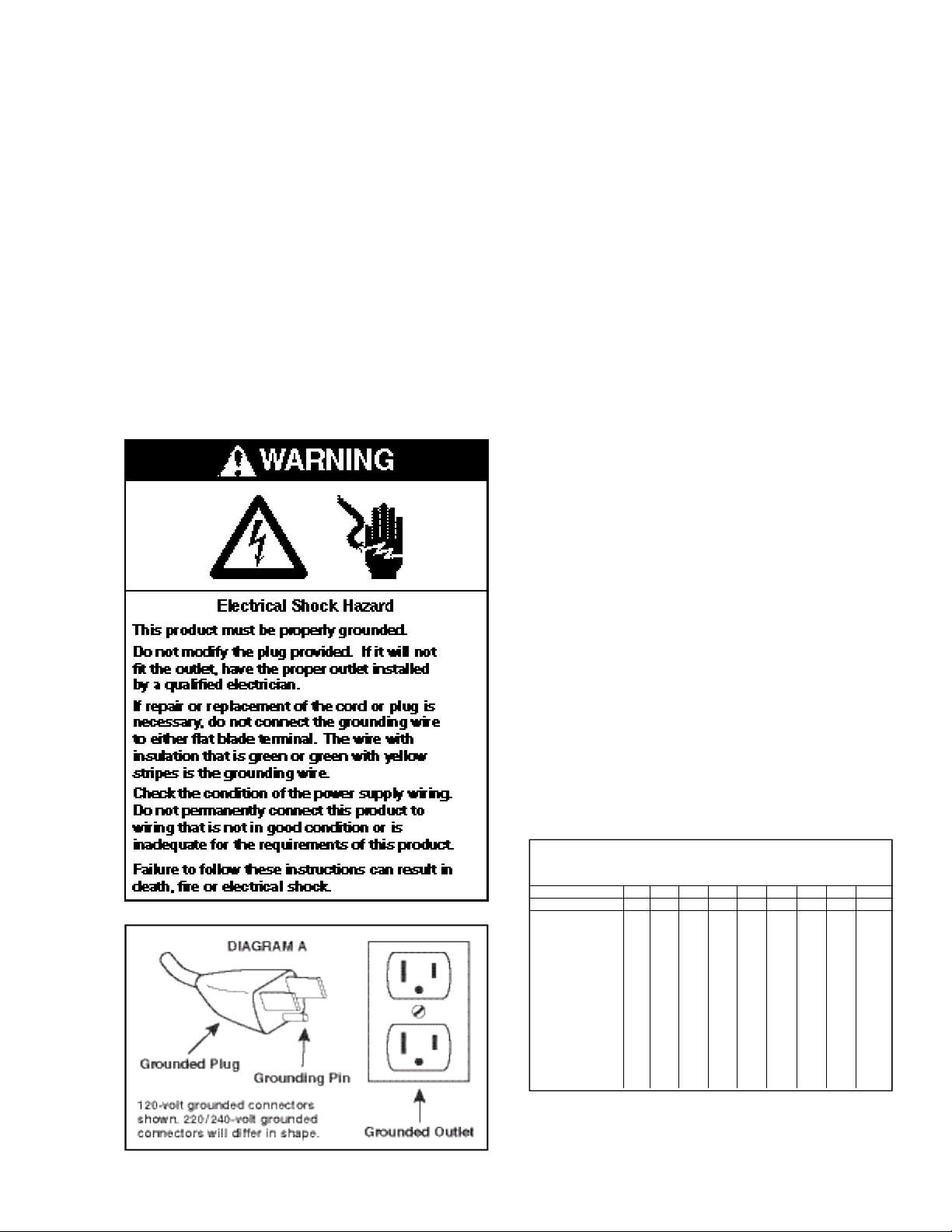
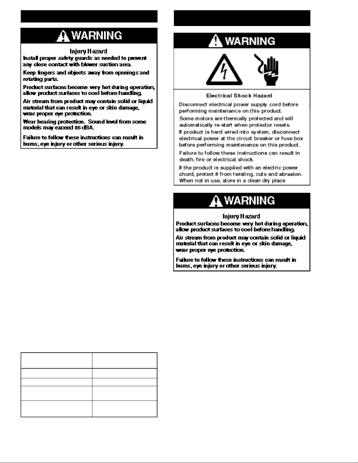
WARNING
DANGER
Plumbing
Remove any foreign material (burrs, chips, welding
drops, slag, pipe cuttings, excess sealant, sand or
lime) from plumbing.
Check motor mounting and rotation before connecting
to plumbing. Inlet and outlet ports are not designed to
support plumbing.
Remove plugs from the IN and OUT ports. Use a small
amount of pipe thread lubricant when connecting
plumbing to protect the aluminum blower threads.
Connect with pipe and fittings that are the same size or
larger than the product’s threaded ports. When
installing two blowers in parallel, use plumbing that is
two whole pipe sizes larger in diameter than that of the
blower. Be sure to connect the intake and exhaust
plumbing to the correct inlet and outlet ports.
Plumbing to remove the hot discharge air of larger
blowers may be required to help maintain proper room
ambient temperature. Use a relief valve to discharge
excess air into the atmosphere. If the blower will be
operated at 125mbar (50” H2O) or higher, metal pipe is
required for hot exhaust air.
Mounting
The single impeller blower should be oriented with the
shaft in a horizontal position, unless the model’s product
features state otherwise. The dual impeller models must
be mounted with the shaft in a horizontal position.
Mounting the product to a stable, rigid operating surface
and using shock mounts will reduce noise and vibration.
Rotation
From the motor side of the blower, check that the blower is
rotating clockwise. (The motor side is marked with an
arrow on most models.) Proper rotation can also be
checked by the air flow at the IN and OUT ports. On
blowers powered by a 3-phase motor, incorrectly
connecting any two power lines can reverse direction.
Motor Installation
It is your responsibility to contact a qualified
electrician and assure that the electrical installation
is adequate and in conformance with all national
and local codes and ordinances.
Select fuses, motor protective switches or thermal
protective switches to provide protection. Fuses act as
short circuit protection for the motor, not as protection
against overload. Incoming line fuses must be able to
withstand the motor’s starting current. Motor starters
with thermal magnetic overload or circuit breakers
protect motor from overload or reduced voltage
conditions. Motors without automatic restart require
thermal protection or magnetic over-current cutout to
prevent motor overloading from one phase in a 3-phase
circuit, high starting frequency or jammed blower.
The power required will rise as differential pressure
increases. The wiring diagram attached to the product
or on page 6 of this manual provides required electrical
information. Large motors have two diagrams, one for
50Hz wiring specifications and the other for 60Hz wiring
specifications. Check that the power source is correct
to properly operate the dual-voltage motor. If additional
information is required, please consult your Gast
Distributor/Representative.
Model with a power supply cord:
This product must be grounded. For either 120-volt or
220/240-volt circuits connect power supply cord
grounding plug to a matching grounded outlet. Do not
use an adapter. (See DIAGRAM A)
Model that is permanently wired:
This product must be connected to a grounded,
metallic, permanent wiring system, or an equipment
grounding terminal or lead on the product.
Power supply wiring must conform to all required safety
codes and be installed by a qualified person. Check
that supply voltage agrees with that listed on product
nameplate.
Extension cords:
Use only a 3-wire extension cord that has a 3-blade
grounding plug. Connect extension cord plug to a
matching 3-slot receptacle. Do not use an adapter.
Make sure your extension cord is in good condition.
Check that the gage wire of the extension cord is the
correct size wire to carry the current this product will
draw.
An undersized cord is a potential fire hazard, and will
cause a drop in line voltage resulting in loss of power
causing the product to overheat. The following table
indicates the correct size cord for length required and
the ampere rating listed on the product nameplate. If in
doubt, use the next heavier gage cord. The smaller
the gage number, the heavier the wire gage.
Check with a qualified electrician or serviceman if
the grounding instructions are not completely
understood, or if you are not sure whether the
product is properly grounded. Do not modify the
plug provided. If it will not fit the outlet, have the
proper outlet installed by a qualified electrician.
In the event of an electrical short circuit, grounding
reduces the risk of electric shock by providing an
escape wire for the electric current. This product may
be equipped with a power supply cord having a
grounding wire with an appropriate grounding plug.
The plug must be plugged into an outlet that is properly
installed and grounded in accordance with all local
codes and ordinances.
Electrical Connection
Minimum gage for extension cords
Amps Volts Length of cord in feet
120v 25 50 100 150 200 250 300 400 500
240v 50 100 200 300 400 500 600 800 1000
0-2 18 18 18 16 16 14 14 12 12
2-3 18 18 16 14 14 12 12 10 10
3-4 18 18 16 14 12 12 10 10 8
4-5 18 18 14 12 12 10 10 8 8
5-6 18 16 14 12 10 10 8 8 8
6-8 18 16 12 10 10 8 6 6 6
8-10 18 14 12 10 8 8 6 6 4
10-12 16 14 10 8 8 6 6 4 4
12-14 16 12 10 8 6 6 6 4 2
14-16 16 12 10 8 6 6 4 4 2
16-18 14 12 8 8 6 4 4 2 2
18-20 14 12 8 6 6 4 4 2 2
Start Up
Operate blower for an hour and then check:
1. Ambient temperature – Check room and discharge
air temperatures. Increased room temperatures
may require stronger ventilation especially for larger
blowers. Exhaust air should not exceed 215ºF
(102ºC) for all blowers less than 3.5 Hp. Exhaust air
should not exceed 275ºF (135ºC) for all blowers
above 3.5 Hp.
2. Working pressure and vacuum values – Adjust
relief valve pressure or vacuum setting, if needed.
3. Motor current – Check that supply current matches
recommended current rating on product nameplate.
4. Electrical overload cutout – Check that current
matches rating on product nameplate.
It is your responsibility to operate this product at
recommended pressures or vacuum duties and
room ambient temperatures. Do not operate R4P or
larger size blowers without air flowing through the
blower. Do not throttle discharge or suction pipe to
reducer capacity. Throttle will increase differential
pressure causing increasing power absorption and
working temperatures.
O P E R AT I O N
If motor fails to start or slows down significantly under
load, shut off and disconnect from power supply. Check
that the voltage is correct for motor and that motor is
turning in the proper direction.
M A I N T E N A N C E
It is your responsibility to regularly inspect and
make necessary repairs to this product in order to
maintain proper operation. Make sure that pressure
and vacuum is released from product before
starting maintenance.
Check filter elements and noise absorbing foam used in
mufflers and clean motor and blower after first 500
hours of operation. Replace filter elements and
determine how frequently mufflers should be checked
during future operation. This one procedure will help
assure the product’s performance and service life.
When there is an increase in the differential pressure
across the inlet filter it is beginning to clog with dirt.
Replace the cartridge when the filter will not come
clean.
Small motor bearings (less than 5.5 Hp) never need to
be greased. Larger motor bearings (greater than 5.5
Hp) have alemite grease fittings. Use a grease gun and
apply one or two strokes of Exxon POLYREX® grease
to the fittings to lubricate larger motor bearings.
Check that all external accessories such as relief
valves and gauges are not damaged before reoperating product.
Hours of Service Relubrication
Per Year Intervals
5,000 3 years
Continual Normal Service 1 year
Seasonal Service (motor 1 year at beginning of
idle for 6 months or more) season
Continuous-high ambients, 6 months
dirty or moist applications
FOR BLOWERS WITH GREASE FITTINGS
 Loading...