

Garmin RV-IN1501 Installation Manual
RV-IN1501
RV INFOTAINMENT SYSTEM
INSTALLATION
INSTRUCTIONS
Important Safety Information
WARNING
See the Important Safety and Product Information guide in the
product box for product warnings and other important
information.
NOTICE
Failure to follow these cautions could result in damage to the
vehicle or poor product performance.
This device must be installed according to these instructions.
Disconnect the vehicle's power supply before beginning to install
this product.
Before applying power to this product, make sure it has been
correctly grounded according to the installation instructions.
You must read all installation instructions before beginning the
installation. If you experience difficulty during the installation,
contact Garmin® Product Support.
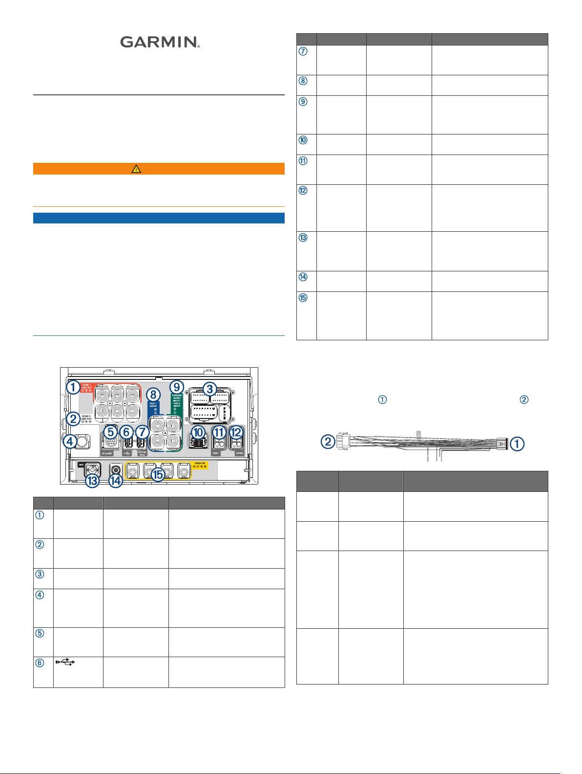
Item Label Description Connector Details
iPhone/iPod USB (1 A) Interfaces with and charges
AUX 1
INPUT
CAMERA
AUDIO
INPUT/AUX
2 INPUT
None Ethernet port Connects to a FUSION
CAN 1 CAN BUS 1 Connects to RV control systems
CAN 2 CAN BUS 2 Reserved for vehicle
MIC Microphone input 3.5 mm mono microphone port
None GPS antenna Connects to the included GPS
VIDEO IN Analog camera
Auxiliary input 1 Left (white) and right (red) RCA
Input for camera
audio or for
auxiliary 2
video input
supported smartphones and
USB devices
connectors
Left (white) and right (red) RCA
connectors
PartyBus™ network
using an adapter (sold
separately)
integration. Connects to the
chassis CAN system using an
adapter cable to support
steering wheel controls.
Connects to the included
microphone for hands-free
calling and voice input
antenna
4 RCA video connectors
Connects to up to four vehicle
cameras, including forward, left
mirror, right mirror, and backup
cameras.
Connector Identification
Item Label Description Connector Details
ZONE 1
LINE OUT
ZONE 2
LINE OUT
None Wiring harness
None AM/FM antenna
SiriusXM SiriusXM® port Connects to a compatible
Line out
connectors for
zone 1
Line out
connectors for
zone 2
connectors
connector
USB (500 mA) Reserved for manufacturer use
Left (white), right (red), and
subwoofer (orange)
RCA connectors
Left (white), right (red), and
subwoofer (orange)
RCA connectors
Connects to the included and
optional wiring harnesses
Connects to either the vehicle's
AM/FM antenna cable or an
inline adapter attached to the
vehicle's AM/FM antenna cable
SiriusXM Connect vehicle tuner
and antenna (sold separately)
Compatible only with lowcurrent (<500 mA) USB devices
Wiring Harnesses
Power and Speaker Wiring Harness
The power and speaker wiring harness contains the main power
and speaker connections for the system. The harness connects
directly to the stereo and to the vehicle wiring harness
without modification. You can use this diagram to troubleshoot
or to address non-default installation requirements.
Wire
Color
Yellow Power (+) Connects to the positive terminal of a
Red Ignition power Connects to a separately-switched,
Orange Illumination Connects to the vehicle's illumination
Black Ground (-) Connects to the negative terminal of a
Function Notes
12 Vdc power source capable of
supplying 15 A.
12 Vdc connection, such as an ignition
bus, to turn the stereo on and off.
wire to dim the stereo screen when the
headlights are on. The gauge of the
illumination wire must be suitable for the
fuse supplying the circuit it is connected
to.
NOTE: This wire is not used for all
vehicles.
12 Vdc power source capable of
supplying 15 A. You should connect this
wire before connecting the yellow wire.
All accessories connected to the stereo
must share a common ground location.
GUID-811CF923-05C5-4722-B874-97869503F42E v2August 2020
Wire
Color
Blue Amplifier on Connects to optional external amplifiers,
Brown Telemute Activates when connected to ground.
Pink Reverse Connects to an analog high signal, such
Red/black House Connects to a 12 Vdc connection for the
White Speaker zone 1
White/
black
Gray Speaker zone 1
Gray/black Speaker zone 1
Green Speaker zone 2
Green/
black
Purple Speaker zone 2
Purple/
black
Function Notes
enabling them to turn on when the
stereo turns on.
For example, when you connect this
wire to a compatible, hands-free mobile
kit, the audio mutes or the input
switches to Aux1 when a call is received
and the kit connects this wire to ground.
You can enable this functionality from
the settings menu.
NOTE: This wire is not used for all
vehicles.
as the reverse light, to activate the
backup camera when the vehicle is
placed in reverse.
RV house power to turn the stereo on
when the house power is turned on.
left (+)
Speaker zone 1
left (-)
right (+)
right (-)
left (+)
Speaker zone 2
left (-)
right (+)
Speaker zone 2
right (-)
Line Out Wiring Harness
The line out wiring harness (sold separately) outputs audio to an
external amplifier for zones 3 and 4.
Label Function RCA connectors
ZONE 3 Outputs analog audio to an
external amplifier for zone 3.
ZONE 4 Outputs analog audio to an
external amplifier for zone 4.
AUX IN 2 Not used. These connectors are
not active for the RV-IN1501
product model. You must use the
CAMERA AUDIO INPUT/AUX 2
INPUT connector on the back of
the stereo instead.
Left (white), right (red),
and sub (orange)
Left (white), right (red),
and sub (orange)
Not used
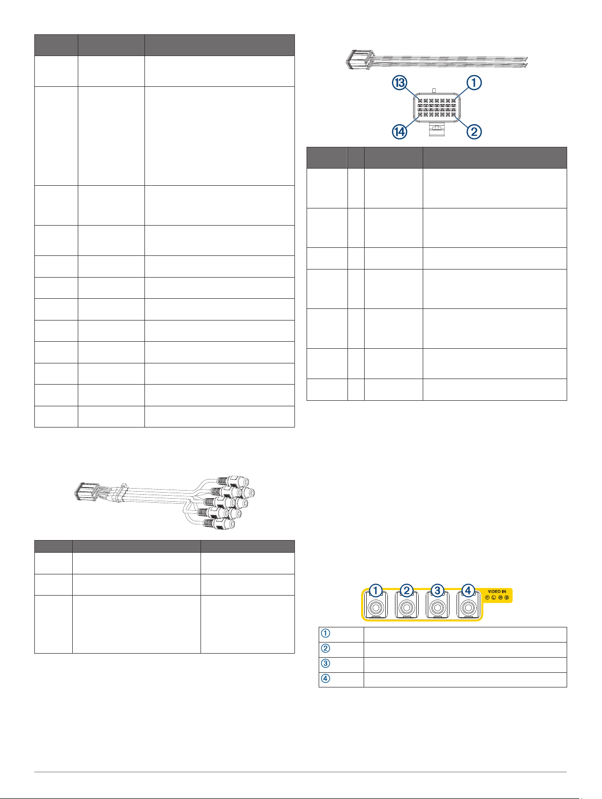
Analog Signal Detect Wiring Harness
Wire
color
Green 1 Analog input 1 Connects to the steering wheel
Purple 2 Analog input 2 Connects to the steering wheel
Black 4 Analog input
Orange 5 Right camera
Blue 6 Left camera
Brown 7 Front camera
Black 9 Camera detect
Pin Function Notes
controls. Not available for all vehicles.
Contact the RV manufacturer for more
information.
controls. Not available for all vehicles.
Contact the RV manufacturer for more
information.
ground
detect
detect
detect
ground
Ground wire for analog steering wheel
control inputs.
Connects to an analog high signal,
such as the right turn signal, to trigger
the device to display the right side
camera.
Connects to an analog high signal,
such as the left turn signal, to trigger
the device to display the left side
camera.
Connects to an analog high signal to
trigger the device to display the front
camera.
Ground wire for the camera detect
inputs.
Connecting Vehicle and Backup Cameras
You can connect up to four analog vehicle cameras to the
infotainment system for backup, left, right, and front cameras.
For each camera, route the camera's RCA analog video
1
cable to the back of the stereo.
You should clearly label each cable for reference when you
are connecting them to the stereo.
For each camera, determine the analog high signal that
2
should trigger the stereo to display the camera, and route a
wire for that signal to the back of the stereo.
For example, you can use a reverse signal to trigger the
backup camera when the vehicle is put in reverse, or you can
use turn signal to trigger a side mirror camera.
Connect each RCA analog video cable to the VIDEO IN
3
connectors on the back of the stereo, as shown.
Front camera
Left camera
Right camera
Backup camera
Connect the analog high signal wire for the backup camera to
4
the pink REVERSE wire of the power and speaker wiring
harness (Power and Speaker Wiring Harness, page 1).
Connect the analog high signal wire for each of the other
5
cameras to the appropriate camera detect wire of the analog
signal detect harness (Analog Signal Detect Wiring Harness,
page 2).
2
 Loading...