

Garmin RV-BBT600 Installation Manual

RV-BBT600 SERIES
INSTALLATION
INSTRUCTIONS
Important Safety Information
WARNING
See the Important Safety and Product Information guide in the
product box for product warnings and other important
information.
NOTICE
Failure to follow these cautions could result in damage to the
vehicle or poor product performance.
This device must be installed according to these instructions.
Disconnect the vehicle's power supply before beginning to install
this product.
Before applying power to this product, make sure it has been
correctly grounded according to the installation instructions.
You must read all installation instructions before beginning the
installation. If you experience difficulty during the installation,
contact Garmin® Product Support.
Item Label Connector
None Wiring harness
ZONE 2 LINE
OUT
AUX 1 INPUT Auxiliary input 1 Left and right RCA
ZONE 3 LINE
OUT
CAMERA
AUDIO
INPUT/AUX 2
INPUT
ZONE 4 LINE
OUT
iPad USB (2.1A) Interfaces and charges
CAN 1 CAN BUS 1 Connects to an NRX wired
CAN 2 CAN BUS 2 Reserved for vehicle
N/A AM/FM antenna Connects to the vehicle
Description
connectors
Line out for zone 2 Left, right, and subwoofer
Line out for zone 3 Left, right, and subwoofer
Input for camera
audio or for
auxiliary 2
Zone 4 line out Left, right, and subwoofer
USB (500mA) Reserved for manufacturer
Notes
The wiring harnesses are
not included. See (Pin
Identification, page 1) for
pinout information.
RCA connectors
connectors
RCA connectors
Left and right RCA
connectors
RCA connectors
use
Compatible only with low-
current (<500 mA) USB
devices
supported smartphones and
USB devices
remote control using an
adapter (sold separately)
integration
antenna. The included
adapter may be required.
Pin Identification
You can use this pinout diagram and table to create a wiring
harness for this device.
Connector Identification
Item Label Connector
MIC Microphone input 3.5 mm mono miniplug for
VIDEO IN Video input Composite video RCA
ZONE 1 LINE
OUT
Description
Line out for zone 1 Left, right, and subwoofer
Notes
the hands-free microphone
(included)
connector
RCA connectors
Pin Function
Speaker: zone 2 left positive (+)
Speaker: zone 2 left negative (-)
Speaker: zone 1 left positive (+)
Speaker: zone 1 left negative (-)
Speaker: zone 1 right positive (+)
Speaker: zone 1 right negative (-)
Speaker: zone 2 right positive (+)
Speaker: zone 2 right negative (-)
Ignition switch positive (+12 Vdc input)
Power ground (-)
GUID-EFC21AFA-2D40-45E8-8E4C-6A9EFBF01CB9 v4July 2020
Pin Function
Amplifier signal (+12 Vdc output)
Dim
Not applicable
Power input positive (+12 Vdc input)
Backup camera (+12 Vdc to trigger)
Tel/mute (ground to trigger)
Connecting a FUSION® NRX Remote Control
You can connect a FUSION NRX remote control (not included)
to the stereo dock using an adapter cable (not included). You
can purchase an NRX remote control and the required adapter
cable from your FUSION dealer.
You can connect up to three NRX remote controls directly to the
stereo dock without connecting them to an additional power
source. If you want to connect more than three NRX remote
controls to the stereo dock, you must connect them to an
additional power source. See the instructions provided with the
remote control for more information.
Install each of the NRX remote controls by following the
1
instructions provided with each remote control.
Route the network cable from the NRX remote control
2
network to the location of the stereo dock.
Connect the adapter cable to the CAN 1 port on the back of
3
the stereo dock.
Connect the cable from the NRX remote control network to
4
the adapter cable.
Select an option:
5
• If the NRX remote control network connects to an
additional power source, continue with the dock
installation.
• If the NRX remote control network does not connect to an
additional power source, proceed to the next step.
Turn on the stereo.
6
On the stereo, from the music player, select > Settings >
7
NRX Power.
When the check box is filled, the dock supplies power and
data to the connected NRX remote controls.
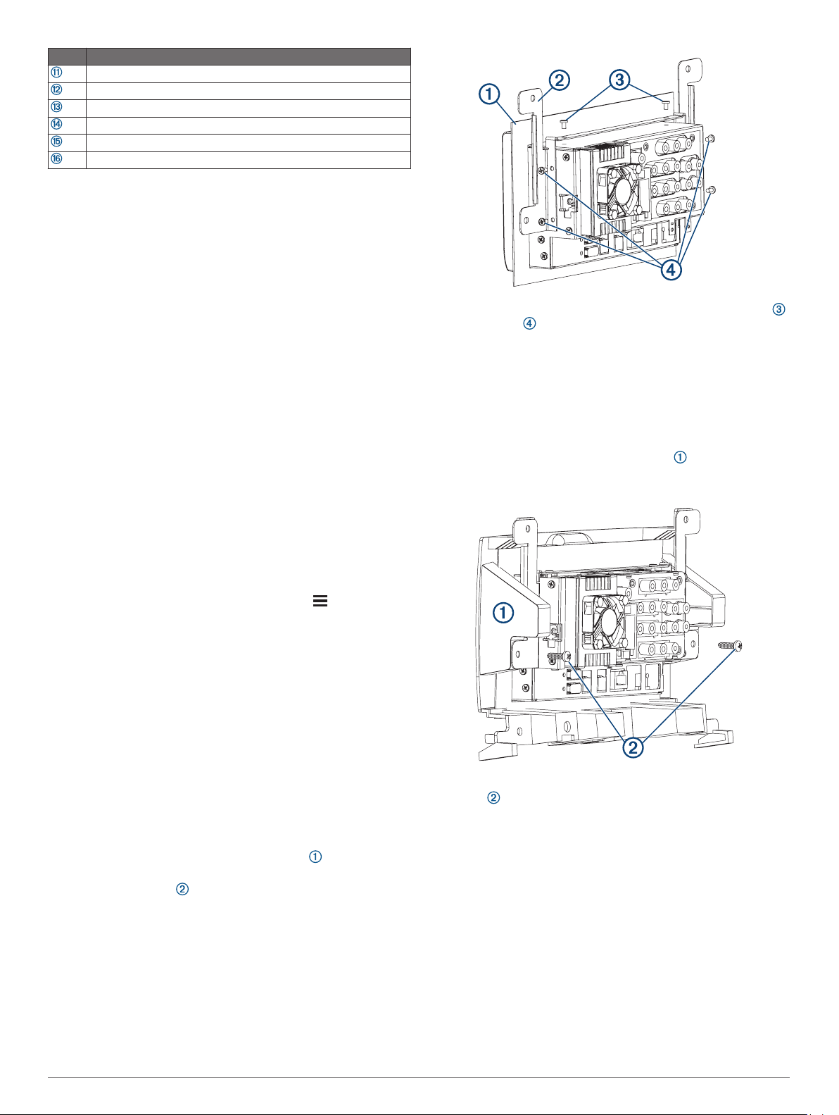
Using the included screws, secure each bracket to the top
3
and the sides of the dock.
Installing the Dock in a Mercedes-Benz Sprinter Dashboard
Before you can install the dock in the dashboard, you must
install the gasket and brackets on the dock.
The product package does not include the hardware required to
fasten the dock bracket to the dashboard or dashboard panel.
If necessary, remove the dashboard panel or components to
1
reach the stereo mounting location.
Place the dock into the dashboard panel , aligning the
2
upper holes in the bracket with the holes in the dashboard
panel.
Dock Installation
You must use the included bracket to install the device dock into
a specific vehicle type.
The product package includes the hardware required to attach
the bracket to the dock. The product package does not include
the hardware to attach the bracket to the dashboard or the
dashboard panel.
Installing the Bracket on the Dock for Mercedes-Benz
Sprinter™ Vehicles
You should use the included screws to attach the bracket to the
dock.
Remove the protective film from the gasket , and slide it
1
over the dock, with the adhesive facing the front of the dock.
Place each bracket on the dock, aligning the holes on the
2
bracket with the holes on the sides and top of the dock.
2
Secure the dock in the dashboard panel using self-tapping
3
®
screws through the lower holes in the bracket.
From inside the dashboard, connect all necessary cables and
4
wires to the dock.
Place the dashboard panel in the dashboard, and secure it
5
using screws through the top and bottom holes.
 Loading...