

Garmin RV 890, CAMPER 890, RV1090, CAMPER1090 Owner's Manual
Getting Started with Easy Altivar ATV610
ENGLISH
Verify the Key
Points of your
installation,
identified
by this symbol.
Verify The Delivery Of The
Drive
Unpack the drive and verify that it has not been damaged.
Damaged products or accessories may cause electric shock or
unanticipated equipment operation.
Contact your local Schneider Electric sales office if you detect any damage
whatsoever.
Verify compatibility between your drive and your
application.
See the ATV610 Catalog DIA2ED2140702EN.
Environment
The drive is suitable for operation in these environments:
• Degree of protection:
IP20
• Mechanical class: 3S3 conforming to IEC/EN 60721
• Chemical class: 3C3 conforming to IEC/EN 60721
DANGER
HAZARD OF ELECTRIC SHOCK, EXPLOSION,
OR ARC FLASH
Do not use damaged products or accessories.
Failure to follow these instructions will result in death or serious
injury.
2
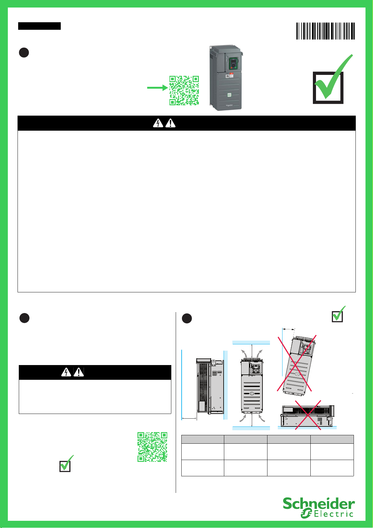
Mount The Drive Vertically
X1X2
X3
u10°
For a surrounding air temperature up to 45 °C (113 °F), and for other thermal
conditions, see installation manual (EAV64381) on se.com
Drive X1 X2 X3
ATV610U07N4...
ATV610D90N4
u 100 mm (3.9 in.) u 100 mm (3.9 in.) u 10 mm (0.39 in.)
ATV610C11N4...
ATV610C16N4
u 250 mm (10 in.) u 250 mm (10 in.) u 10 mm (0.39 in.)
EAV6437406
1
Download The Manuals
You must have detailed information to be able to carry out the installation and
commissioning. This information can be found in the following manuals that
can be downloaded on www.se.com
or scan the QR code in front of the Drive.
- The ATV610 Installation manual (EAV64381)
- The ATV610 Programming manual (EAV64387)
The Getting Started manual does not replace the Installation
and the Programming manuals.
DANGER
HAZARD OF ELECTRIC SHOCK, EXPLOSION, OR ARC FLASH
Only appropriately trained persons who are familiar with and understand the contents of this manual and all other pertinent product documentation and who
have received safety training to recognize and avoid hazards involved are authorized to work on and with this drive system. Installation, adjustment, repair and
maintenance must be performed by qualified personnel.
• The system integrator is responsible for compliance with all local and national electrical code requirements as well as all other applicable regulations with
respect to grounding of all equipment.
• Many components of the product, including the printed circuit boards, operate with mains voltage.
• Only use properly rated, electrically insulated tools and measuring equipment.
• Do not touch unshielded components or terminals with voltage present.
• Motors can generate voltage when the shaft is rotated. Prior to performing any type of work on the drive system, block the motor shaft to prevent rotation.
• AC voltage can couple voltage to unused conductors in the motor cable. Insulate both ends of unused conductors of the motor cable.
• Do not short across the DC bus terminals or the DC bus capacitors or the braking resistor terminals.
• Before performing work on the drive system:
• Disconnect all power, including external control power that may be present. Take into account that the circuit breaker or main switch does not de-energize
all circuits.
• Place a Do Not Turn On label on all power switches related to the drive system.
• Lock all power switches in the open position.
• Wait 15 minutes to allow the DC bus capacitors to discharge.
• Follow the instructions given in the chapter "Verifying the Absence of Voltage" in the installation manual of the product.
• Before applying voltage to the drive system:
• Verify that the work has been completed and that the entire installation cannot cause hazards.
• If the mains input terminals and the motor output terminals have been grounded and short-circuited, remove the ground and the shor t ci rcu its on the ma ins
input terminals and the motor output terminals.
• Verify proper grounding of all equipment.
• Verify that all protective equipment such as covers, doors, grids is installed and/or closed.
Failure to follow these instructions will result in death or serious injury.
Electrical equipment should be installed, operated, serviced, and maintained only by qualified personnel. No responsibility is assumed by Schneider Electric for any
consequences arising out of the use of this product.
3
www.se.com 1/4 EAV64374 - 04/2020
4
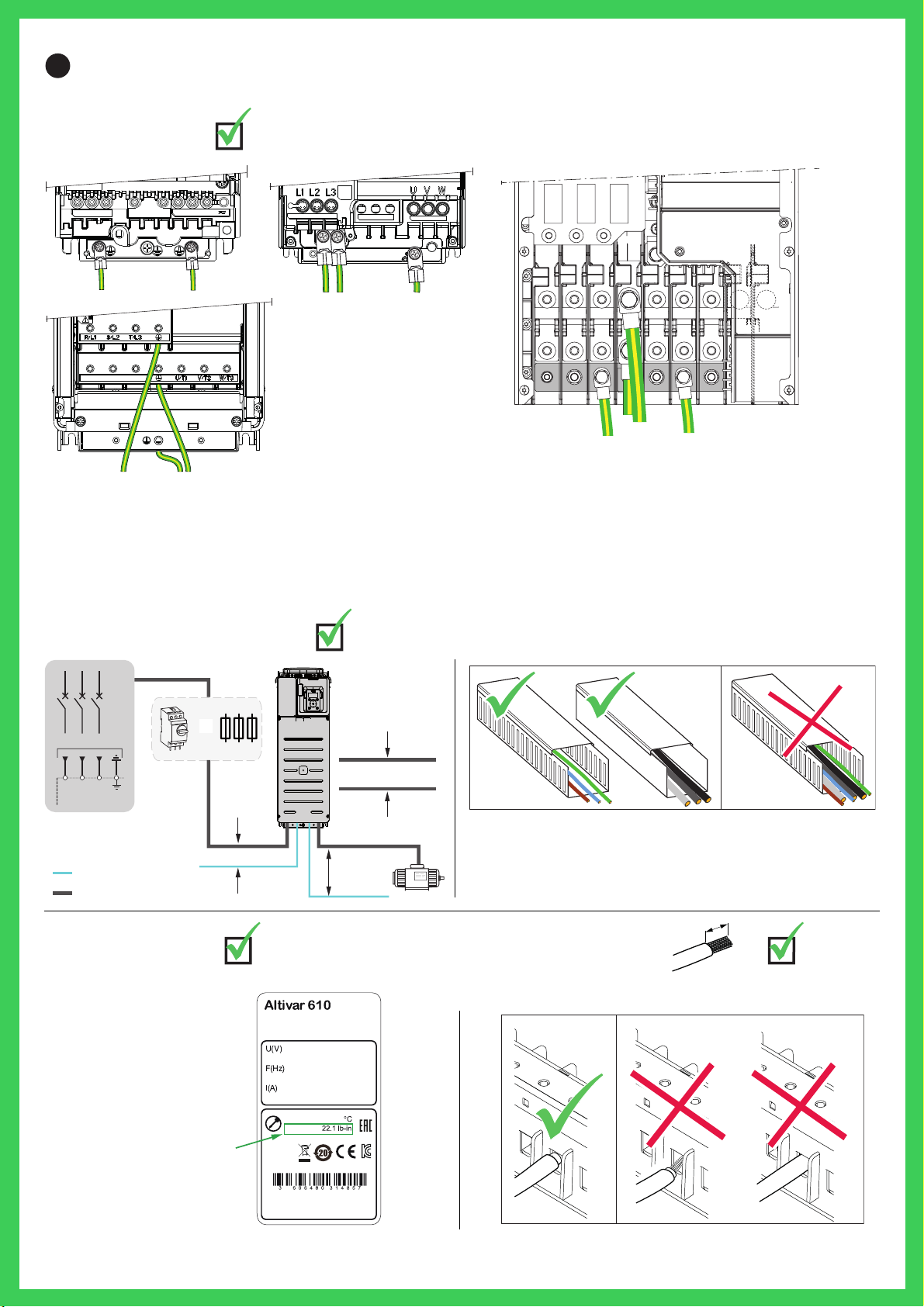
L1
R
L2SL3
T
UT1VT2W
T3
PE
PA/+PC/
-
PA/+PA/+
PC/-PC/-
PA/ +PA/+ PC/-PC/-
L1L1 L2L2 L3L 3L1 L2 L3 PA/+ PC/- U V W
> 500 mm
(20 in.)
> 200 mm (8 in.)
> 300 mm (12 in.)
3 a 380/415 V
R/L1
S/L2
T/L3
Control
Power
OR
Download the white paper An Improved Approach for Connecting VSD
and Electric Motors (998-2095-10-17-13AR0_EN).
V1.0 IE 00 18.5kW
ATV610D18N4
10mm² 70Cu
IP20
1.8 N.m
50/60
380-415Φ3
0...380-415Φ3Output
Output
Output
0...500
37.2MAX
39.2
Made in China
Schneider Electric Industries SAS
35 Rue Joseph Monier
FR-92500 Rueil Malmaison
www.se.com/contact
Input
Input
Input
KCC-REI-SEk
-ATV610D18N4
xx N.m xx lb-in
Refer to the tightening torque
instructions on the name plate.
Stripping lengths
Refer to the instructions given in the installation manual
(EAV64381)
Tightening torque
Connect The Drive: Power Part
Ground the drive
Verify the ratings
• Verify circuit breaker rating or fuse rating (see the ATV610 Catalog DIA2ED2140702EN).
• Verify that the nominal motor voltage is compatible with the drive voltage. Nominal motor voltage ______volts.
Cable the power part
Minimum distance between the cables
24 V 380 V
www.se.com 2/4 EAV64374 - 04/2020
 Loading...