

Page 1
REACTOR™ 40 KICKER
THROTTLE ACTUATOR
INSTALLATION
INSTRUCTIONS
Important Safety Information
WARNING
See the
product box for product warnings and other important
information.
You are responsible for the safe and prudent operation of your
vessel. The autopilot is a tool that enhances your capability to
operate your boat. It does not relieve you of the responsibility of
safely operating your boat. Avoid navigational hazards and
never leave the helm unattended.
Always be prepared to promptly regain manual control of your
boat.
If your motor features a kill switch, you should know how to
operate it in case of an emergency. If your motor does not
feature a kill switch, you should install one before installing the
autopilot system.
Learn to operate the autopilot on calm and hazard-free open
water.
Use caution when operating the autopilot near hazards in the
water, such as docks, pilings, and other boats.
When in use, beware of hot surfaces on the heat-sink, motor,
and solenoid components.
When in use, beware the risk of entrapment or pinching from
moving parts.
Failure to install and maintain this equipment in accordance with
these instructions could result in damage or injury.
Tools Needed
• Wrenches
• Phillips screwdriver
• Marine sealant
• Loctite® thread lock (for Honda® motor installs)
Parts Identification
The throttle actuator is the component of the Reactor 40 Kicker
autopilot system that controls the speed of the motor.
You must install the throttle actuator inside the motor housing
and connect it to the carburetor throttle lever using the linkage
parts supplied in this package. Different motor types require
different linkage parts, and the parts are separated into separate
bags. These instructions refer to the labels on the bags when
discussing the parts needed for different motor types.
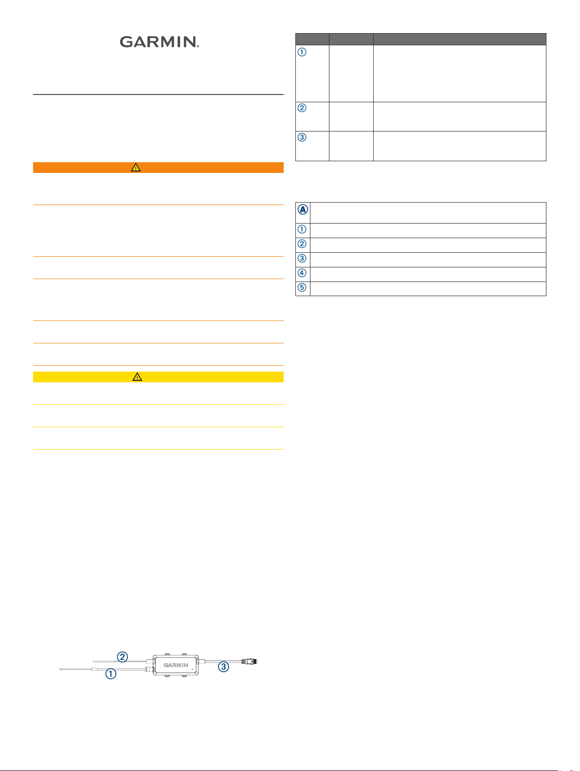
Throttle Actuator
Important Safety and Product Information guide in the
CAUTION
Number Part Notes
Throttle
cable
RPM cable Connects to the spark plug to measure the
ECU cable Connects the throttle actuator to the ECU of the
Connects to the carburetor linkage to pull open
the carburetor and control the speed of the
motor.
Consult the section for your motor type for
details about how to connect this cable to the
carburetor linkage.
motor RPM (Connecting the RPM Cable,
page 5).
autopilot system (Connecting the Throttle
Actuator to the ECU
, page 5).
Parts Bags
You should refer to this table to determine which parts apply to
your motor type.
Common parts. These parts are used when installing the actuator
on all motor types.
Parts for 8 through 9.9 horsepower Yamaha® motors.
Parts for 15 through 20 horsepower Yamaha motors.
Parts for 8 through 9.9 horsepower Mercury® motors.
Parts for 15 through 20 horsepower Mercury EFI motors.
Parts for 8 through 20 horsepower Honda motors.
Installation Preparation
Mounting and Connection Considerations
When preparing to install the throttle actuator, observe the
following considerations:
• You must install the throttle actuator inside the motor
housing.
• Most motors use a throttle linkage to control the carburetor
throttle lever. You should replace the factory-installed throttle
linkage with the provided throttle linkage to prevent the
throttle actuator from back-driving the throttle on the tiller
(Tiller Back Drive Considerations, page 1).
• You must secure the throttle cable to the motor manifold and
connect it to the carburetor throttle lever on the motor using
the included bracket and linkage specific to your motor type.
• You can place the throttle actuator box in any available space
inside the motor housing after you secure the throttle cable to
the manifold and route the other cables. You can use the
included large zip ties to secure the throttle actuator box
inside the motor housing to keep it from moving during use.
• You must secure the RPM cable to the outside of a spark
plug cable (Connecting the RPM Cable, page 5).
• You must connect the throttle actuator to the ECU of the
autopilot system using the provided cable run from inside the
motor housing (Connecting the Throttle Actuator to the ECU,
page 5).
Tiller Back Drive Considerations
Most motors use a throttle linkage to control the carburetor
throttle lever. This linkage opens and closes the carburetor
when you adjust the throttle on the tiller arm. Because the
autopilot throttle actuator controls the speed of the motor from
inside the motor housing, you should replace the factoryinstalled throttle linkage with the provided throttle linkage. This
prevents the throttle actuator from back-driving the throttle on
the tiller arm, but still allows you to use the throttle on the tiller
arm when you are not using the autopilot system to control the
motor.
See the connections diagram for your motor type to locate the
existing throttle linkage and replace it with the included linkage.
NOTE: Because of the motor design, you cannot replace the
throttle linkage on Honda motors. Under typical operation, the
February 2019
190-02451-94_0A
Page 2
throttle actuator back-drives the throttle on the tiller arm on
Honda motors, and you must adjust the friction collar on the
throttle to allow the actuator to control the speed of the motor
(Adjusting the Throttle Friction, page 5).
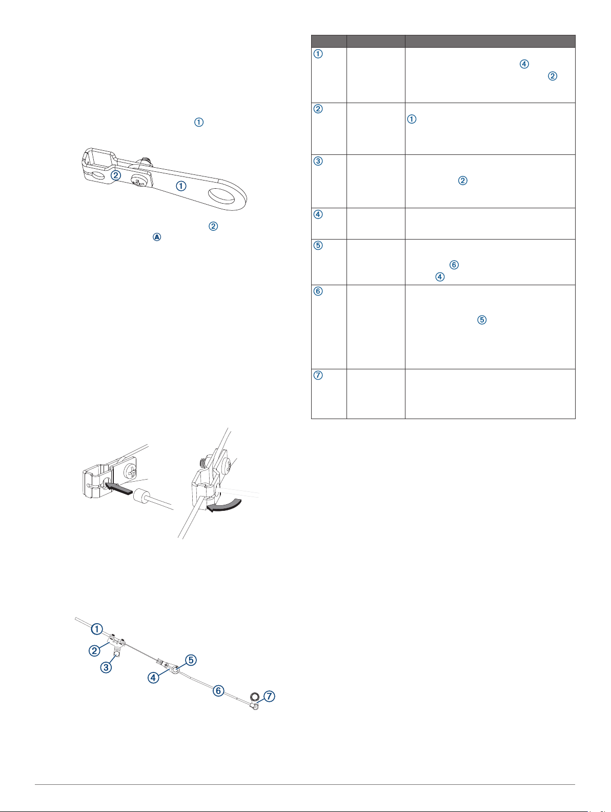
Assembling the Carburetor Linkage
The carburetor linkage allows the throttle cable from the actuator
to pull open the carburetor throttle lever on the motor.
Remove the carburetor linkage arm from the bag
1
containing the parts for your motor.
Remove the carburetor linkage bracket from the bag
2
containing common parts .
Using the bolt and nut in the bag containing common parts,
3
connect the carburetor linkage bracket to the carburetor
linkage arm on the tapered end of the arm.
Tighten the nut so the bracket is securely connected to the
4
arm, but loose enough so the bracket moves freely.
Connecting the Throttle Actuator Cable to the Carburetor Linkage
The carburetor linkage is designed to hold the cable from the
throttle actuator securely. Because of the design, you must
connect the throttle actuator cable to the carburetor linkage
before you secure the parts to the motor.
If necessary, assemble the carburetor linkage (Assembling
1
the Carburetor Linkage, page 2).
Place the round end of the throttle actuator cable into the
2
hole on the end of the carburetor linkage.
Number Part Notes
Throttle
actuator cable
(from the
throttle
actuator box)
Throttle cable
bracket
Manifold
mounting
location
Carburetor
linkage
Motor
carburetor
throttle lever
Tiller throttle
linkage rod
Tiller throttle
linkage
You should connect the throttle actuator
cable to the carburetor linkage before
securing it to the throttle cable bracket
(Connecting the Throttle Actuator Cable to
the Carburetor Linkage, page 2).
You must secure the throttle actuator cable
to the throttle cable bracket using the
included zip ties (Securing the Throttle
Actuator Cable to the Bracket for Most Motor
Types, page 5).
You must remove the existing bolt on the
manifold and use it to secure the throttle
cable bracket .
You may need to move the hose connected
to the bolt to properly secure the bracket.
You must assemble the carburetor linkage
before installing it (Assembling the
Carburetor Linkage, page 2).
You must remove the set screw on the
throttle lever to disconnect the tiller throttle
linkage rod and install the carburetor
linkage and plastic washers.
You do not replace this rod when installing
the other linkage parts, but you must remove
it temporarily to secure the carburetor linkage
to the throttle lever .
TIP: You can mark the location on the rod
where it connects to the throttle lever so it is
easier to note the proper motor idle when you
reconnect it.
You must replace this linkage component
with the new part provided in the parts bag.
You should save the linkage component in
case you need to restore the motor to its
factory configuration in the future.
Rotate the cable so it feeds through the slot on the end of the
3
linkage.
Yamaha 8 through 9.9 Horsepower
Connections
Setting the Linkage Components for Proper Idle
After you install the throttle actuator components on the motor,
you must adjust them so the motor idles correctly.
Loosen the throttle actuator bracket on the engine manifold
1
until the throttle actuator does not pull open the carburetor
throttle lever.
There should be obvious slack in the throttle actuator cable.
Adjust the tiller throttle to idle, start the motor, and complete
2
an action:
• If the motor is not idling correctly, loosen the set screw on
the carburetor throttle lever, adjust the tiller throttle linkage
rod until the motor idles correctly, and tighten the set
screw.
• If the motor idles correctly, proceed to the next step.
Using the tiller throttle, increase the speed of the motor, and
3
complete an action:
• If the motor does not increase its speed and return to idle
correctly, repeat the previous step to adjust the tiller
throttle linkage rod.
• If the motor increases its speed and returns to idle
correctly, proceed to the next step.
Adjust the position of the throttle actuator bracket until no
4
slack remains in the throttle actuator cable and the motor
idles correctly.
Tighten the throttle actuator bracket on the engine manifold
5
to set the cable tension.
If necessary, turn off the motor.
6
2
Page 3

Yamaha 15 through 20 Horsepower Connections
Number Part Notes
Throttle actuator
cable (from the
throttle actuator
box)
Throttle cable
bracket
Manifold
mounting
location
Carburetor
linkage
Motor
carburetor
throttle lever
Tiller throttle
linkage barrelslider
mechanism
You should connect the throttle actuator
cable to the carburetor linkage before
securing it to the throttle cable bracket
(Connecting the Throttle Actuator Cable to
the Carburetor Linkage, page 2).
You must secure the throttle actuator cable
to the throttle cable bracket using the
included zip ties (Securing the Throttle
Actuator Cable to the Bracket for Most
Motor Types, page 5).
You must remove the existing bolt on the
manifold and use it to secure the throttle
cable bracket.
You must assemble the carburetor linkage
before installing it (Assembling the
Carburetor Linkage, page 2).
You must remove the set screw on the
throttle lever to disconnect the tiller throttle
linkage rod and install the carburetor
linkage .
You must replace the existing tiller throttle
linkage rod with the barrel-slider
mechanism provided in the parts bag
(Assembling the Barrel Slider Throttle
Linkage, page 3). You should save the
existing tiller throttle linkage rod in case you
need to restore the motor to its factory
configuration in the future.
Setting the Linkage Components for Proper Idle
After you install the throttle actuator components on the motor,
you must adjust them so the motor idles correctly.
Loosen the throttle actuator bracket on the engine manifold
1
until the throttle actuator does not pull open the carburetor
throttle lever.
There should be obvious slack in the throttle actuator cable.
Loosen the set screw on the carburetor throttle lever, and
2
slide the rod into the barrel slider until it stops.
Tighten the set screw.
3
Adjust the tiller throttle to idle, start the motor, and complete
4
an action:
• If the motor is not idling correctly, loosen the set screw on
the carburetor throttle lever, adjust the tiller throttle linkage
rod in the barrel slider until the motor idles correctly, and
tighten the set screw.
• If the motor idles correctly, proceed to the next step.
Using the tiller throttle, increase the speed of the motor, and
5
complete an action:
• If the motor does not increase its speed and return to idle
correctly, repeat the previous step to adjust the tiller
throttle linkage rod in the barrel slider.
• If the motor increases its speed and returns to idle
correctly, proceed to the next step.
Adjust the position of the throttle actuator bracket until no
6
slack remains in the throttle actuator cable and the motor
idles correctly.
Tighten the throttle actuator bracket on the engine manifold
7
to set the cable tension.
If necessary, turn off the motor.
8
Mercury 8 through 9.9 Horsepower
Connections
Assembling the Barrel Slider Throttle Linkage
For some motors, you must replace the existing throttle linkage
with a barrel-slider mechanism to prevent back-driving the tiller
throttle.
If necessary, open the parts bag for your motor model, and
1
remove the barrel-slider mechanism parts.
Insert the small bent rod into the short end of the barrel .
2
The flat portion of the small rod fits into the barrel one way
only.
Secure the small rod using the set screw .
3
Insert the round end of the long rod into the other side of
4
the barrel.
Number Part Notes
Throttle
actuator cable
(from the
throttle actuator
box)
Throttle cable
bracket
Manifold
mounting
location
Carburetor
linkage
You should connect the throttle actuator
cable to the carburetor linkage before
securing it to the throttle cable bracket
(Connecting the Throttle Actuator Cable to
the Carburetor Linkage, page 2).
You must secure the throttle actuator cable
to the throttle cable bracket using the
included zip ties (Securing the Throttle
Actuator Cable to the Bracket for Most Motor
Types, page 5).
You must remove the existing bolt on the
manifold and use it to secure the throttle
cable bracket .
You must assemble the carburetor linkage
before installing it (Assembling the
Carburetor Linkage, page 2).
3
Page 4

Number Part Notes
Motor
carburetor
throttle lever
Tiller throttle
linkage rod
You must remove the set screw on the
throttle lever to disconnect the tiller throttle
linkage rod and install the carburetor
linkage and plastic washers.
You must replace the existing tiller throttle
linkage rod with the new rod provided in the
parts bag. You should save the existing tiller
throttle linkage rod in case you need to
restore the motor to its factory configuration
in the future.
Number Part Notes
Carburetor
linkage
Motor
carburetor
throttle lever
Tiller throttle
linkage
You must assemble the carburetor linkage
before installing it (Assembling the
Carburetor Linkage, page 2).
You must disconnect the tiller throttle
linkage from the throttle lever to install
the carburetor linkage .
You must modify the factory tiller throttle
linkage using the new part provided in the
parts bag (Modifying the Tiller Throttle
Linkage, page 4).
Setting the Linkage Components for Proper Idle
After you install the throttle actuator components on the motor,
you must adjust them so the motor idles correctly.
Loosen the throttle actuator bracket on the engine manifold
1
until the throttle actuator does not pull open the carburetor
throttle lever.
There should be obvious slack in the throttle actuator cable.
Adjust the tiller throttle to idle, start the motor, and complete
2
an action:
• If the motor is not idling correctly, loosen the set screw on
the carburetor throttle lever, adjust the tiller throttle linkage
rod until the motor idles correctly, and tighten the set
screw.
• If the motor idles correctly, proceed to the next step.
Using the tiller throttle, increase the speed of the motor, and
3
complete an action:
• If the motor does not increase its speed and return to idle
correctly, repeat the previous step to adjust the tiller
throttle linkage rod.
• If the motor increases its speed and returns to idle
correctly, proceed to the next step.
Adjust the position of the throttle actuator bracket until no
4
slack remains in the throttle actuator cable and the motor
idles correctly.
Tighten the throttle actuator bracket on the engine manifold
5
to set the cable tension.
If necessary, turn off the motor.
6
Mercury 15 through 20 Horsepower Connections
Securing the Throttle Actuator Cable to the Bracket for Mercury 15 through 20 Horsepower Motors
Before securing the cable to the bracket, you should connect the
end of the throttle actuator cable to the carburetor linkage
(Connecting the Throttle Actuator Cable to the Carburetor
Linkage, page 2).
NOTE: This type of bracket is used to secure the throttle
actuator cable for the Mercury 15 through 20 horsepower motor
only. If you are installing the throttle actuator on all other motor
types, you must follow the instructions for that bracket instead
(Securing the Throttle Actuator Cable to the Bracket for Most
Motor Types, page 5).
Place the top of the bracket over the raised portion of the
1
throttle actuator cable .
Secure the cable to the bracket using the included screws .
2
Modifying the Tiller Throttle Linkage
On Mercury 15 through 20 horsepower motors, you must modify
the tiller throttle linkage to prevent the throttle actuator from
back-driving the tiller throttle.
Disconnect the existing tiller throttle linkage from the motor.
1
Remove one end of the linkage and the nut by
2
unscrewing the rod .
Number Part Notes
Throttle
actuator cable
(from the
throttle actuator
box)
Throttle cable
bracket
Manifold
mounting
location
4
You should connect the throttle actuator
cable to the carburetor linkage before
securing it to the throttle cable bracket
(Connecting the Throttle Actuator Cable to
the Carburetor Linkage, page 2).
You must secure the throttle actuator cable
to the throttle cable bracket using the
screws on the bracket (Securing the Throttle
Actuator Cable to the Bracket for Mercury
15 through 20 Horsepower Motors,
page 4).
You must remove the existing bolt on the
manifold and use it to secure the throttle
cable bracket .
Store the rod and other end of the linkage in case you need
3
to restore the motor to factory condition in the future.
Screw the existing nut onto the replacement rod from the
4
parts bag.
Screw the existing end of the linkage onto the replacement
5
rod.
Setting the Linkage Components for Proper Idle
Loosen the two screws that hold the throttle actuator cable to
1
the bracket until the throttle actuator does not pull open the
carburetor throttle lever.
There should be obvious slack in the throttle actuator cable.
Page 5

Adjust the tiller throttle to idle, start the motor, and complete
2
an action:
• If the motor is not idling correctly, remove the tiller throttle
linkage and adjust the length of the rod until the motor
idles correctly.
• If the motor idles correctly, proceed to the next step.
Using the tiller throttle, increase the speed of the motor, and
3
complete an action:
• If the motor does not increase its speed and return to idle
correctly, repeat the previous step to adjust the tiller
throttle linkage.
• If the motor increases its speed and returns to idle
correctly, proceed to the next step.
Adjust the position of the throttle actuator cable in the bracket
4
until no slack remains in the cable and the motor idles
correctly.
Tighten the two screws to secure the throttle actuator cable
5
to the bracket and set the cable tension.
If necessary, turn off the motor.
6
Honda 8 through 20 Horsepower Connections
The friction collar adjusts the tension on the tiller throttle, and
when fully tightened, keeps the throttle at a set position.
Adjust the friction collar so that it is fully loosened.
2
The throttle actuator is able to control the speed of the motor
only when the friction collar is fully loosened.
Common Installation Procedures
These procedures are the same for all motor models.
Securing the Throttle Actuator Cable to the Bracket for Most Motor Types
Before you secure the cable to the bracket, you should connect
the end of the throttle actuator cable to the carburetor linkage
(Connecting the Throttle Actuator Cable to the Carburetor
Linkage, page 2).
NOTE: This type of bracket is used to secure the throttle
actuator cable for most motor types. If you are installing the
throttle actuator on a Mercury 15 through 20 horsepower motor,
you must follow the instructions for that bracket instead
(Securing the Throttle Actuator Cable to the Bracket for Mercury
15 through 20 Horsepower Motors, page 4).
Place the raised portion of the throttle actuator cable into
1
the bracket between the raised tabs .
Number Part Notes
Throttle
actuator cable
(from the
throttle
actuator box)
Throttle cable
bracket
Manifold
mounting
location
Carburetor
linkage
You should connect the throttle actuator cable
to the carburetor linkage before securing it
to the throttle cable bracket (Connecting
the Throttle Actuator Cable to the Carburetor
Linkage, page 2).
You must secure the throttle actuator cable to
the throttle cable bracket using the included
zip ties (Securing the Throttle Actuator Cable
to the Bracket for Most Motor Types,
page 5).
You must loosen the existing bolt on the
manifold and slide the throttle cable bracket
into place .
You should not remove the bolt from the
manifold, because it is difficult to put the bolt
back in place after it has been removed.
You must assemble the carburetor linkage
before installing it (Assembling the Carburetor
Linkage, page 2).
The carburetor linkage arm is keyed to fit one
way on the carburetor only.
You must remove the existing lock washer to
install the carburetor linkage bracket, and you
should apply Loctite thread lock to the bolt
when securing the bracket.
Adjusting the Throttle Friction
Because the throttle actuator back-drives the tiller throttle on
Honda motors, you must adjust the throttle friction on the tiller
arm for the actuator to work properly.
Locate the friction collar on the tiller arm.
1
Secure the cable to the bracket using the included zip ties .
2
Connecting the RPM Cable
NOTICE
You must not cut or strip the RPM cable or the spark plug cable.
Cutting or stripping either cable will result in damage to the
throttle actuator, the motor, or both.
The RPM cable monitors engine RPM, and is needed for proper
autopilot operation.
Route the RPM cable from the throttle actuator box to a spark
1
plug cable on the motor.
Secure the RPM cable to the outside of the spark plug cable
2
using the included zip ties.
Connecting the Throttle Actuator to the ECU
After you connect the throttle actuator and linkages inside the
motor, you must connect the throttle actuator to the autopilot
ECU.
Locate the cable pass-through location on the motor.
1
This area is where the motor cables are routed from the
inside of the motor to the outside of the motor, and is usually
near the tiller arm.
If necessary, create a cable pass-through opening in the
2
motor housing for the ECU cable.
5
Page 6

Route the ECU cable on the throttle actuator from the inside
3
of the motor to the outside of the motor.
Route the ECU cable to the location where you installed the
4
autopilot ECU, and connect it to the THROTTLE port.
If necessary, apply marine sealant to the cable pass-through
5
opening to protect the inside of the motor from water ingress.
Testing the Throttle Actuator Installation
Before you can test the installation, you must install all of the
autopilot components and all of the throttle actuator linkage
components, and connect the throttle actuator to the ECU.
Turn on the motor.
1
Turn on the autopilot system.
2
Engage the autopilot.
3
On the remote control, press to increase the throttle using
4
the throttle actuator.
The throttle actuator should move the throttle to full speed.
On the remote control, press to decrease the throttle using
5
the throttle actuator.
The throttle actuator should return the motor to idle.
Complete an action:
6
• If the throttle actuator does not move the throttle from full
speed to idle, adjust the throttle cable bracket and repeat
this test.
• If the throttle actuator controls the throttle correctly, turn
off the motor and the autopilot system.
Specifications
Dimensions (L × W × H) 151 × 60 × 23 mm (6 × 2.35 × 0.9 in.)
Weight 181 g (6.4 oz.)
Temperature range From 0° to 70°C (from 32° to 158°F)
Material Glass-reinforced nylon and aluminum
Water rating* Throttle actuator housing: IEC 60529 IPX7*
ECU cable length 3 m (9 ft.)
Input voltage From 12 to 24 Vdc
*The device withstands incidental exposure to water of up to 1 m
for up to 30 min. For more information, go to www.garmin.com
/waterrating.
© 2019 Garmin Ltd. or its subsidiaries
Garmin® and the Garmin logo are trademarks of Garmin Ltd. or its subsidiaries,
registered in the USA and other countries. Reactor™ is a trademark of Garmin Ltd. or its
subsidiaries. This trademark may not be used without the express permission of Garmin.
Honda® is a registered trademark of Honda Motor Co., Ltd. and its subsidiaries and
Loctite® is a trademark of Henkel Corporation in the U.S. and elsewhere.
affiliates.
Mercury® is a trademark of Brunswick Corporation. NMEA®, NMEA 2000®, and the NMEA
2000 logo are trademarks of the National Marine Electronics Association.
trademark of the Yamaha Motor Corporation.
Yamaha® is a
support.garmin.com
 Loading...