

Page 1

Integrated Flight Deck
Cockpit Reference Guide
Piper
PA32
Page 2

Page 3

Copyright © 2004-2007 Garmin Ltd. or its subsidiaries. All rights reserved.
This manual reflects the operation of System Software version 0648.02 or later for the Piper PA32. Some differences in operation may
be observed when comparing the information in this manual to earlier or later software versions.
Garmin International, Inc., 1200 East 151st Street, Olathe, Kansas 66062, U.S.A.
Tel: 913/397.8200 Fax: 913/397.8282
Garmin AT, Inc., 2345 Turner Road SE, Salem, OR 97302, U.S.A.
Tel: 503/391.3411 Fax 503/364.2138
Garmin (Europe) Ltd., Unit 5, The Quadrangle, Abbey Park Industrial Estate, Romsey, Hampshire S051 9DL, U.K.
Tel: 44/0870.851241 Fax: 44/0870.8501251
Garmin Corporation, No. 68, Jangshu 2nd Road, Shijr, Taipei County, Taiwan
Tel: 886/02.2642.9199 Fax: 886/02.2642.9099
Web Site Address: www.garmin.com
Except as expressly provided herein, no part of this manual may be reproduced, copied, transmitted, disseminated, downloaded or
stored in any storage medium, for any purpose without the express written permission of Garmin. Garmin hereby grants permission
to download a single copy of this manual and of any revision to this manual onto a hard drive or other electronic storage medium to
be viewed for personal use, provided that such electronic or printed copy of this manual or revision must contain the complete text
of this copyright notice and provided further that any unauthorized commercial distribution of this manual or any revision hereto is
strictly prohibited.
Garmin® and G1000® are registered trademarks of Garmin Ltd. or its subsidiaries. FliteCharts™, and SafeTaxi™ are trademarks of
Garmin Ltd. or its subsidiaries. These trademarks may not be used without the express permission of Garmin.
NavData® is a registered trademark of Jeppesen, Inc.; Stormscope® and SkyWatch® are registered trademarks of L-3 Communications;
and XM® is a registered trademark of XM Satellite Radio, Inc.
January 2007 190-00416-01 Rev. C Printed in the U.S.A.
Garmin G1000 Cockpit Reference Guide for the Piper PA32
Page 4

WARNINGS,
CAUTIONS, & NOTES
WARNING: Navigation and terrain separation must NOT be predicated upon the use of the terrain function.
The G1000 Terrain Proximity feature is NOT intended to be used as a primary reference for terrain avoidance
and does not relieve the pilot from the responsibility of being aware of surroundings during flight. The Terrain
Proximity feature is only to be used as an aid for terrain avoidance and is not certified for use in applications
requiring a certified terrain awareness system. Terrain data is obtained from third party sources. Garmin is
not able to independently verify the accuracy of the terrain data.
WARNING: The displayed minimum safe altitudes (MSAs) are only advisory in nature and should not be relied
upon as the sole source of obstacle and terrain avoidance information. Always refer to current aeronautical
charts for appropriate minimum clearance altitudes.
WARNING: The altitude calculated by G1000 GPS receivers is geometric height above Mean Sea Level and could
vary significantly from the altitude displayed by pressure altimeters, such as the GDC 74A Air Data Computer,
or other altimeters in aircraft. GPS altitude should never be used for vertical navigation. Always use pressure
altitude displayed by the G1000 PFD or other pressure altimeters in aircraft.
WARNING: Do not use outdated database information. Databases used in the G1000 system must be updated
regularly in order to ensure that the information remains current. Pilots using any outdated database do so
entirely at their own risk.
WARNING: Do not use basemap (land and water data) information for primary navigation. Basemap data is
intended only to supplement other approved navigation data sources and should be considered as an aid to
enhance situational awareness.
WARNING: Traffic information shown on the G1000 Multi Function Display is provided as an aid in visually
acquiring traffic. Pilots must maneuver the aircraft based only upon ATC guidance or positive visual acquisition
of conflicting traffic.
WARNING: Use of the Stormscope is not intended for hazardous weather penetration (thunderstorm penetration).
Stormscope information, as displayed on the G1000 MFD, is to be used only for weather avoidance, not
penetration.
WARNING: GDL 69 Weather should not be used for hazardous weather penetration. Weather information
provided by the GDL 69 is approved only for weather avoidance, not penetration.
Garmin G1000 Cockpit Reference Guide for the Piper PA32
Page 5

WARNINGS,
CAUTIONS, & NOTES
WARNING: NEXRAD weather data is to be used for long-range planning purposes only. Due to inherent delays
in data transmission and the relative age of the data, NEXRAD weather data should not be used for short-range
weather avoidance.
WARNING: The Garmin G1000, as installed in the Piper PA32 aircraft, has a very high degree of functional
integrity. However, the pilot must recognize that providing monitoring and/or self-test capability for all
conceivable system failures is not practical. Although unlikely, it may be possible for erroneous operation to
occur without a fault indication shown by the G1000. It is thus the responsibility of the pilot to detect such an
occurrence by means of cross-checking with all redundant or correlated information available in the cockpit.
WARNING: For safety reasons, G1000 operational procedures must be learned on the ground.
WARNING: The United States government operates the Global Positioning System and is solely responsible
for its accuracy and maintenance. The GPS system is subject to changes which could affect the accuracy
and performance of all GPS equipment. Portions of the Garmin G1000 utilize GPS as a precision electronic
NAVigation AID (NAVAID). Therefore, as with all NAVAIDs, information presented by the G1000 can be misused
or misinterpreted and, therefore, become unsafe.
WARNING: To reduce the risk of unsafe operation, carefully review and understand all aspects of the G1000
Pilot’s Guide documentation and the Piper PA32 Pilot’s Operating Handbook (POH). Thoroughly practice basic
operation prior to actual use. During flight operations, carefully compare indications from the G1000 to all
available navigation sources, including the information from other NAVAIDs, visual sightings, charts, etc. For
safety purposes, always resolve any discrepancies before continuing navigation.
WARNING: The illustrations in this guide are only examples. Never use the G1000 to attempt to penetrate a
thunderstorm. Both the FAA Advisory Circular, Subject: Thunderstorms, and the Airman’s Information Manual
(AIM) recommend avoiding “by at least 20 miles any thunderstorm identified as severe or giving an intense
radar echo.”
CAUTION: The GDU 1040A PFDs and GDU 1500 MFD displays use a lens coated with a special anti-reflective
coating that is very sensitive to skin oils, waxes, and abrasive cleaners. CLEANERS CONTAINING AMMONIA
WILL HARM THE ANTI-REFLECTIVE COATING. It is very important to clean the lens using a clean, lint-free cloth
and an eyeglass lens cleaner that is specified as safe for anti-reflective coatings.
Garmin G1000 Cockpit Reference Guide for the Piper PA32
Page 6

WARNINGS,
CAUTIONS, & NOTES
CAUTION: The Garmin G1000 does not contain any user-serviceable parts. Repairs should only be made by
an authorized Garmin service center. Unauthorized repairs or modifications could void both the warranty and
the pilot’s authority to operate this device under FAA/FCC regulations.
NOTE: When using Stormscope, there are several atmospheric phenomena in addition to nearby thunderstorms
that can cause isolated discharge points in the strike display mode. However, clusters of two or more discharge
points in the strike display mode do indicate thunderstorm activity if these points reappear after the screen has
been cleared.
NOTE: All visual depictions contained within this document, including screen images of the G1000 panel and
displays, are subject to change and may not reflect the most current G1000 system. Depictions of equipment
may differ slightly from the actual equipment.
NOTE: This device complies with part 15 of the FCC Rules. Operation is subject to the following two conditions:
(1) this device may not cause harmful interference, and (2) this device must accept any interference received,
including interference that may cause undesired operation.
NOTE: This product, its packaging, and its components contain chemicals known to the State of California to
cause cancer, birth defects, or reproductive harm. This notice is being provided in accordance with California’s
Proposition 65. If you have any questions or would like additional information, please refer to our web site at
www.garmin.com/prop65.
Garmin G1000 Cockpit Reference Guide for the Piper PA32
Page 7
Part Number Change Summary
190-00416-00
Rev A
Initial release.
RECORD OF REVISIONS
Rev B
Revised for system software version 0426.01
190-00416-01
Rev A Added GDU 7.0 software parameters, WAAS, VNAV, electronic
charts, TAWS, and full EIS display.
190-00416-01
Rev B
Added GDU 8.00 parameters, Airways, new MFD splash screen
Changed VNAV to VNV
Revision Date of Revision Affected Pages Description
C January, 2007 10-7, 10-13,
10-14
Corrected range display in Figure 10-11.
Updated Figure 10-19.
Added Negative Climb Rate Figure 10-21
Garmin G1000 Cockpit Reference Guide for the Piper PA32
RR-1
Page 8

RECORD OF REVISIONS
Blank Page
RR-2
Garmin G1000 Cockpit Reference Guide for the Piper PA32
Page 9

TABLE OF CONTENTS
SECTION 1: SYSTEM OVERVIEW .................................... 1-1
1.1 PFD/MFD Controls ................................................... 1-2
1.2 PFD Softkeys ............................................................ 1-4
1.3 MFD Softkeys ..........................................................1-7
1.4 MFD Page Groups ................................................... 1-8
1.5 Vertical Navigation ................................................ 1-8
1.6 Backlighting ........................................................... 1-10
1.7 Database Updates ................................................ 1-10
Jeppesen Aviation Database ...................................... 1-11
Garmin Databases ..................................................... 1-11
1.8 Pilot Profiles .......................................................... 1-12
Creating a Profile ......................................................1-12
Selecting a Profile .....................................................1-12
Renaming a Profile .................................................... 1-12
Deleting a Profile ......................................................1-13
SECTION 2: FLIGHT INSTRUMENTS .............................. 2-1
2.1 Airspeed Indicator .................................................. 2-3
Speed Indication .........................................................2-3
Airspeed Trend Vector ................................................. 2-3
Vspeed References ...................................................... 2-3
True Airspeed Box ........................................................2-3
2.2 Attitude Indicator ..................................................2-3
2.3 Altimeter ..................................................................2-4
Altitude Reference Bug ................................................ 2-4
Altitude Trend Vector ................................................... 2-4
Barometric Setting Box ................................................ 2-4
Altitude Alerting .......................................................... 2-4
Metric Display .............................................................2-4
2.4 Vertical Deviation/Glidepath/Glideslope
Indicator ...................................................................2-5
2.5 Marker Beacon Annunciations ............................2-6
2.6 Vertical Speed Indicator ....................................... 2-6
2.7 Barometric Altitude Minimums ...........................2-6
2.8 Wind Data ................................................................. 2-7
2.9 Horizontal Situation Indicator (HSI) ................... 2-8
Turn Rate Indicator and Heading Trend Vector .............. 2-8
Course Pointer ............................................................ 2-8
Course Deviation Indicator (CDI) .................................. 2-9
Bearing Pointers and Information Windows ................ 2-10
DME (optional) .......................................................... 2-10
Navigation Source ..................................................... 2-10
2.10 Generic Timer ........................................................2-11
SECTION 3: ENGINE INDICATION SYSTEM (EIS) ....3-1
3.1 Default Engine Display .......................................... 3-1
3.2 Full EIS Display ........................................................ 3-2
Leaning Assist (Normally Aspirated Engine Only) .......... 3-3
SECTION 4: NAV/COM AND TRANSPONDER .......... 4-1
4.1 Radio Status Indications ....................................... 4-3
4.2 Volume ...................................................................... 4-3
4.3 Automatic Squelch ................................................. 4-3
4.4 Quickly Activating 121.500 MHz .......................... 4-3
4.5 Optional NAV Radios ............................................. 4-3
DME Radio (optional) .................................................. 4-3
ADF Radio (optional) ................................................... 4-3
4.6 Frequency Auto-tuning .........................................4-4
Auto-tuning on the PFD .............................................. 4-4
Auto-tuning on the MFD .............................................4-4
4.7 Transponder ............................................................. 4-4
Mode Selection ...........................................................4-4
Reply Status ................................................................ 4-5
Code Selection ............................................................ 4-5
Flight ID Reporting ...................................................... 4-6
SECTION 5: AUDIO PANEL ................................................ 5-1
5.1 COM Radio Selection .............................................5-2
5.2 Split COM Function ................................................5-2
5.3 Marker Beacon Receiver ....................................... 5-2
Marker Beacon Signal Sensitivity .................................5-3
5.4 Nav Radio Audio Selection ................................... 5-3
5.5 Intercom System (ICS) Isolation .......................... 5-3
5.6 Intercom Squelch Control ..................................... 5-4
5.7 Digital Clearance Recorder and Player .............5-4
SECTION 6: AUTOMATIC FLIGHT CONTROL ............. 6-1
SECTION 7: NAVIGATION .................................................. 7-1
7.1 Navigation Map Page ............................................ 7-1
Select the MAP Page Group ......................................... 7-1
7.2 Direct-to Navigation ..............................................7-1
Direct-to Navigation from the MFD .............................. 7-1
Direct-to Navigation from the PFD ............................... 7-3
7.3 Navigating an Example Flight Plan ....................7-5
7.4 Airport Information ............................................. 7-22
7.5 Intersection Information ....................................7-24
7.6 NDB Information ................................................... 7-25
Garmin G1000 Cockpit Reference Guide for the Piper PA32
i
Page 10

TABLE OF CONTENTS
7.7 VOR Information ................................................... 7-25
7.8 User Waypoint Information Page .....................7-26
7.9 Nearest Airports ................................................... 7-26
Nearest Airport Information on the MFD .................... 7-26
Nearest Airports Information on the PFD .................... 7-27
7.10 Nearest Intersections ..........................................7-27
7.11 Nearest NDB .......................................................... 7-28
7.12 Nearest VOR ...........................................................7-28
7.13 Nearest User Waypoint ........................................ 7-29
7.14 Nearest Frequencies ............................................7-29
7.15 Nearest Airspaces ................................................. 7-30
SECTION 8: FLIGHT PLANNING ...................................... 8-1
8.1 User Defined Waypoints ........................................ 8-1
Select the User WPT Information Page ......................... 8-1
Create User Waypoints from the Navigation Map Page . 8-2
8.2 Viewing the Active Flight Plan ............................ 8-2
8.3 Activate a Stored Flight Plan ............................... 8-2
8.4 Activate a Flight Plan Leg ....................................8-3
8.5 Stop Navigating a Flight Plan .............................. 8-3
8.6 Invert Active Flight Plan .......................................8-3
8.7 Create a New Flight Plan ...................................... 8-4
Create a New Flight Plan Using the MFD ..................... 8-4
Create a New Flight Plan Using the PFD ......................8-4
8.8 Enter an Airway in a Flight Plan .........................8-5
8.9 Load a Departure ...................................................8-6
8.10 Load an Arrival ........................................................ 8-6
8.11 Load an Approach .................................................. 8-6
8.12 Remove a Departure, Arrival, Approach, or
Airway from a Flight Plan ....................................8-6
8.13 Store a Flight Plan .................................................. 8-7
8.14 Edit a Stored Flight Plan .......................................8-7
8.15 Delete a Waypoint from the Flight Plan ............ 8-7
8.16 Invert and Activate a Stored Flight Plan .......... 8-7
8.17 Copy a Flight Plan .................................................. 8-8
8.18 Delete a Flight Plan ............................................... 8-8
8.19 Graphical Flight Plan Creation ............................ 8-8
8.20 Trip Planning ............................................................ 8-8
SECTION 9: PROCEDURES ................................................9-1
9.1 Arrivals and Departures ........................................ 9-1
Load and Activate a Departure Procedure ....................9-1
Load and Activate An Arrival Procedure ........................ 9-1
9.2 Approaches .............................................................. 9-2
Load and/or Activate an Approach Procedure ............... 9-3
Activate An Approach in the Active Flight Plan .............9-3
SECTION 10: HAZARD AVOIDANCE ...........................10-1
10.1 Customizing the Hazard Displays on the
Navigation Map .................................................... 10-1
10.2 STORMSCOPE® (Optional) ................................... 10-1
Displaying Stormscope Lightning Data on the
Navigation Map Page ................................................ 10-1
Stormscope Page ....................................................... 10-2
10.3 XM Weather (Optional) .......................................10-3
Displaying METAR and TAF information on the
Airport Information Page ........................................... 10-3
Displaying Weather on the Weather Data Link Page ... 10-4
Map Panning Information – Weather Data Link Page .10-5
Weather Products and Symbols .................................10-5
Weather Product Age ................................................10-6
10.4 Traffic Information Service (TIS) ....................... 10-7
Displaying Traffic on the Traffic Map Page ................... 10-7
Displaying Traffic on the Navigation Map ...................10-7
TIS Voice Alert ........................................................... 10-7
10.5 Skywatch® Traffic Advisory System (TAS)
(Optional) ............................................................... 10-8
Displaying Traffic on the Traffic Map Page ................... 10-8
Displaying Traffic on the Navigation Map ...................10-8
10.6 Terrain And Obstacle Proximity ........................10-9
Displaying Terrain and Obstacles on the Terrain
Proximity Page .......................................................... 10-9
Displaying Terrain and Obstacles on the Navigation
Map ........................................................................ 10-10
10.7 Terrain Awareness & Warning System
(TAWS)Display (Optional) ................................. 10-10
Displaying Terrain on the TAWS Page ....................... 10-10
Enable/Disable Aviation Data ................................... 10-12
TAWS Inhibit ........................................................... 10-12
Manual System Test ................................................. 10-12
Forward Looking Terrain Avoidance (FLTA) ................ 10-12
Premature Descent Alert (PDA) ................................ 10-13
Excessive Descent Rate Alert (EDR) .......................... 10-13
Negative Climb Rate After TakeoffAlert (NCR) .......... 10-13
“Five-Hundred” Aural Alert ...................................... 10-14
Displaying Terrain and Obstacles on the Navigation
Map ........................................................................ 10-14
ii
Garmin G1000 Cockpit Reference Guide for the Piper PA32
Page 11

Pop-up Alerts ..........................................................10-14
TAWS Alerts Summary .............................................10-15
Alert Annunciations ................................................. 10-16
SECTION 11: ABNORMAL OPERATION ..................... 11-1
11.1 Reversionary Mode ..............................................11-1
11.2 Abnormal COM Operation ..................................11-1
11.3 Unusual Attitudes ................................................. 11-2
11.4 Stormscope Operation with Loss of
Heading Input ........................................................ 11-2
11.5 Hazard Displays with Loss of GPS Position .... 11-2
11.6 Dead Reckoning .................................................... 11-2
SECTION 12: ANNUNCIATIONS & ALERTS .............. 12-1
12.1 Alert Level Definitions ........................................ 12-2
12.2 Aircraft Alerts ........................................................ 12-3
WARNING Alerts ....................................................... 12-3
CAUTION Alerts ........................................................12-3
Annunciation Advisory ............................................... 12-3
12.3 TAWS Alerts ............................................................ 12-4
TAWS System Status Annunciations ........................... 12-5
12.4 Other G1000 Aural Alerts .................................... 12-5
12.5 G1000 System Message Advisories ..................12-5
Message Advisory Alerts ............................................ 12-8
MFD & PFD Message Advisories .................................12-8
Database Message Advisories .................................... 12-9
GMA 1347 Message Advisories ............................... 12-11
GIA 63W Message Advisories .................................. 12-11
GEA 71 Message Advisories ....................................12-14
GTX 33 Message Advisories .....................................12-14
GRS 77 Message Advisories ..................................... 12-14
GMU 44 Message Advisories ................................... 12-15
GDL 69A Message Advisories .................................. 12-15
GDC 74A Message Advisories .................................. 12-15
Miscellaneous Message Advisories ........................... 12-16
TABLE OF CONTENTS
INDEX ...................................................................................Index-1
Garmin G1000 Cockpit Reference Guide for the Piper PA32
iii
Page 12

TABLE OF CONTENTS
Blank Page
iv
Garmin G1000 Cockpit Reference Guide for the Piper PA32
Page 13

SECTION 1
SYSTEM OVERVIEW
SECTION 1: SYSTEM OVERVIEW
The purpose of this Cockpit Reference Guide is
to provide the pilot a resource with which to find
operating instructions on the major features of the
G1000 system more easily. It is not intended to be a
comprehensive operating guide. Complete operating
procedures for the complete system are found in the
G1000 Pilot’s Guide for the Piper PA32 (190-00692-00):
This guide gives the pilot abbreviated operating
instructions for the Primary Flight Display (PFD), Multi
Function Display (MFD), and the GMA 1347 Audio Panel
System.
NOTE: The pilot should read and thoroughly
understand the Piper PA32 Pilot’s Operating
Handbook (POH) for limitations, procedures and
operational information not contained in this
Cockpit Reference Guide. The POH always takes
precedence over the information found in this
guide.
Garmin G1000 Cockpit Reference Guide for the Piper PA32
1-1
1-1
Page 14
SECTION 1
SYSTEM OVERVIEW
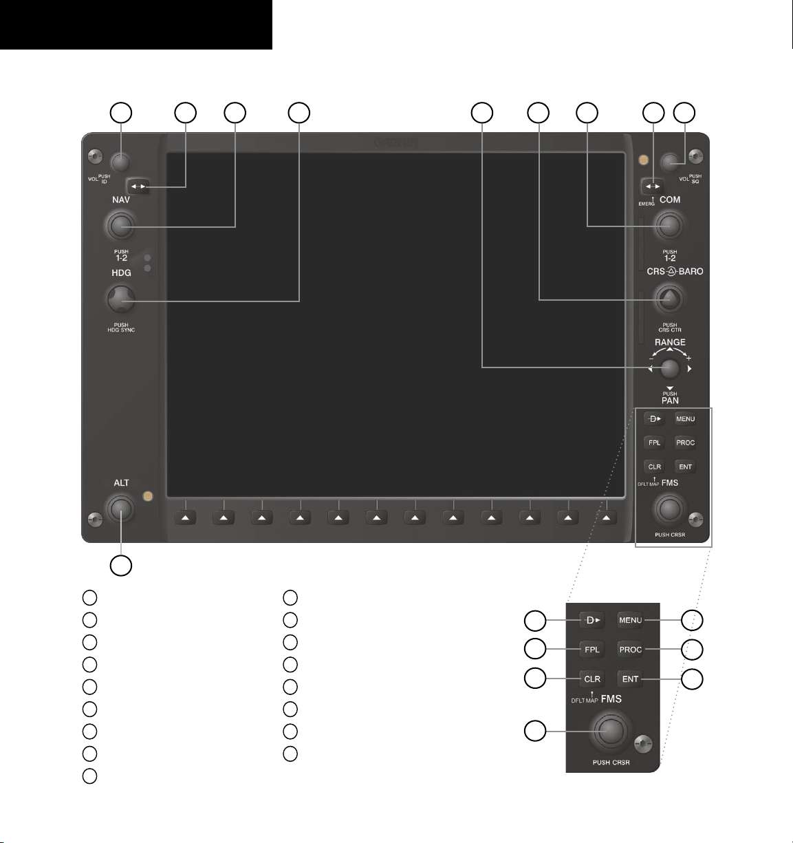
1.1 PFD/MFD CONTROLS
3
421 6
5
7
8
9
1-2
17
1
NAV VOL/ID Knob
2
NAV Frequency Transfer Key
3
NAV Knob
4
Heading Knob
5
Range/Joystick
6
Course/Baro Knob
7
COM Knob
8
COM Frequency Transfer Key
9
COM VOL/SQ Knob
Figure 1-1 PFD/MFD Controls
10
Direct-to Key
11
Flight Plan Key
12
Clear Key
13
Flight Management System Knob
14
Menu Key
15
Procedure Key
16
Enter Key
17
Altitude Knob
10
11
12
13
Garmin G1000 Cockpit Reference Guide for the Piper PA32
14
15
16
Page 15

SECTION 1
SYSTEM OVERVIEW
(1) NAV VOL/ID Knob – Controls the NAV audio level.
Press to turn the Morse code identifier ON and OFF.
Volume level is shown in the field as a percentage.
(2) NAV Frequency Transfer Key – Switches the standby
and active NAV frequencies.
(3) Dual NAV Knob – Tunes the MHz (large knob)
and kHz (small knob) standby frequencies for the NAV
receiver. Press to switch the tuning cursor (light blue box)
between the NAV1 and NAV2 fields.
(4) Heading Knob – Turn to manually select a heading on
the HSI. When pressed, it synchronizes the heading bug
with the compass lubber line.
Joystick – Changes the map range (distance top to
(5)
bottom of map display) when rotated. Activates the map
pointer when pressed.
CRS/BARO Knob – The large knob sets the altimeter
(6)
barometric pressure and the small
knob adjusts the course.
The course is only adjustable when the HSI is in VOR1,
VOR2, or OBS/SUSP Mode. Pressing this knob centers the
CDI on the currently selected VOR.
Dual COM Knob – Tunes the MHz (large knob)
(7)
and kHz (small knob) standby frequencies for the COM
transceiver. Pressing this knob switches the tuning cursor
(light blue box) between the COM1 and COM2 fields.
(8) COM Frequency Transfer Key – Swtiches the standby
and active COM frequencies. Pressing and holding this
key for two seconds automatically tunes the emergency
frequency (121.5 MHz) in the active frequency field.
(9) COM VOL/SQ Knob – Controls COM audio level.
Pressing this knob turns the COM automatic squelch ON
and OFF. Audio volume level is shown in the field as a
percentage.
(10) Direct-to Key – Allows the user to enter a destination
waypoint and establish a direct course to the selected
destination (specified by the identifier, chosen from the
active route, or taken from the map pointer position).
(11) FPL Key – Displays the active Flight Plan Page for
creating and editing the active flight plan, or for accessing
stored flight plans.
(12) CLR Key (DFLT MAP) – Erases information,
cancels an entry, or removes page menus. To display the
Navigation Map Page immediately, press and hold CLR
(MFD only).
(13)
Dual FMS Knob – Used to select the page to be
viewed (only on the MFD). The large knob selects a page
group (MAP, WPT, AUX, NRST), while the small knob
selects a specific page within the page group. Pressing the
small knob turns the selection cursor ON and OFF. When
the cursor is ON, data may be entered in the different
windows using the small and large knobs. The large
knob is used to move the cursor on the page, while the
small knob is used to select individual characters for the
highlighted cursor location. When a list that is too long
for the display screen, a scroll bar appears along the right
side of the display, indicating the availability of additional
items within the selected category. Press the FMS Knob to
activate the cursor and turn the large FMS Knob to scroll
through the list.
(14) MENU Key – Displays a context-sensitive list of
options. This list allows the user to access additional
features, or to make setting changes that relate to certain
pages.
(15) PROC Key – Selects approaches, departures and
arrivals from the flight plan. If a flight plan is used,
available procedures for the departure and/or arrival
airport are automatically suggested. If a flight plan is not
used, the desired airport and the desired procedure may be
selected. This key selects IFR departure procedures (DPs),
arrival procedures (STARs) and approaches (IAPs) from
the database and loads them into the active flight plan.
(16) ENT Key – Accepts a menu selection or data entry.
This key is used to approve an operation or complete data
entry. It is also used to confirm selections and information
entries.
(17) Dual ALT Knob – Sets the reference altitude above
the Altimeter. The large knob selects the thousands, the
small knob selects the hundreds. Selected altitude provides
an altitude setting to the altitude alerter function.
Garmin G1000 Cockpit Reference Guide for the Piper PA32
1-3
Page 16
SECTION 1
VOR1
VOR2
GPS
DME
ALERTS
Press the BACK or OFF Softkey
to return to the top-level softkeys.
ALERTSSTRMSCP
DME
ALERTS
SYSTEM OVERVIEW
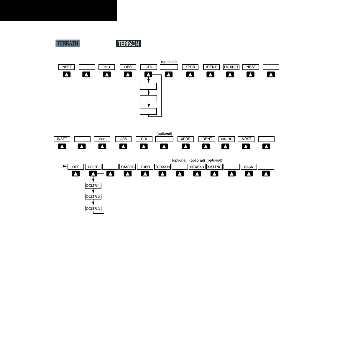
1.2 PFD SOFTKEYS
Softkey ON
Softkey OFF
Figure 1-2 Top Level PFD Softkeys
Figure 1-3 INSET Softkeys
1-4
INSET – Press to display the Inset Map in the lower
left corner of the PFD.
OFF
– Press to remove the Inset Map.
DCLTR
(3) – Press momentarily to select the desired
amount of map detail. The declutter level appears
adjacent to the DCLTR Softkey.
- No declutter: All map features are visible.
- Declutter – 1: Declutters land data.
- Declutter – 2: Declutters land and SUA data.
- Declutter – 3: Declutters large NAV data
remaining (removes everything except the
active flight plan).
TRAFFIC
– Press to display traffic on the map.
Garmin G1000 Cockpit Reference Guide for the Piper PA32
TOPO
– Press to display topographical data (i.e.,
coastlines, terrain, rivers, lakes, etc.) and
elevation scale on the inset map.
TERRAIN
– Press to display terrain information on
the inset map.
STRMSCP (optional)
Stormscope lightning data on the Inset Map
– Press to display the
(within a 200 nm radius of the aircraft).
NEXRAD (optional)
– Press to display NEXRAD
weather and coverage information.
XM LTNG (optional) –
Press to display XM lightning
information.
BACK
– Press to return to the previous level softkey
configuration.
Page 17
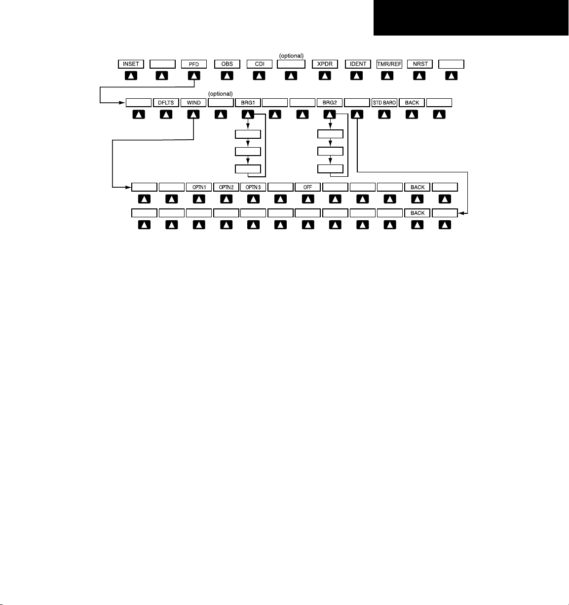
Figure 1-4 PFD Configuration Softkeys
Press the STD BARO or
BACK Softkey to return to
the top-level softkeys
BRG2 (NAV2)
BRG2 (GPS)
BRG2 (OFF)
BRG1 (NAV1)
BRG1 (GPS)
BRG1 (OFF)
DME
ALT UNIT
METERS IN HPA
DME
ALERTS
ALERTS
ALERTS
ALERTS
SECTION 1
SYSTEM OVERVIEW
PFD – Press to display the additional softkeys for
additional configurations to the PFD.
DFLTS
– Press to reset default settings on the PFD.
WIND
– Displays softkeys to select wind data
parameters.
OP T N 1
– Long i t u di n a l and la t e r al
components.
OPTN 2
OPTN 3
– Total direction and speed.
– Total direction with headwind and
crosswind speed components.
OFF
– Information not displayed.
DME
(optional) – Press to display the DME
Information Window.
BRG1 (bearing)
– Press to cycle through the
following information:
NAV1
– Displays NAV1 waypoint frequency or
identifier and GPS-derived distance information
in the BRG1 Information Window.
GPS
– Displays GPS waypoint identifier and
GPS-derived distance information in the BRG1
Information Window.
ADF
– Displays ADF in the BRG1 Information
Window.
OFF
– Removes the BRG1 Information Window.
BRG2 (bearing)
following information:
NAV2
identifier and GPS-derived distance information
in the BRG2 Information Window.
GPS
GPS-derived distance information in the BRG2
Information Window.
ADF
Window.
OFF
Window.
ALT UNIT
altimeter and BARO settings to metric units:
METERS
meters.
IN
of mercury.
HPA
hectopacals.
STD BARO
to 29.92 inches of mercury (1013 hPa if metric
units is selected).
BACK
– Press to cycle through the
– Displays NAV2 waypoint frequency or
– Displays GPS waypoint identifier and
– Displays ADF in the BRG2 Information
– Remo ves the BRG2 Info rmation
– Displays softkeys for setting the
– When enabled, displays altimeter in
– Press to display the BARO setting as inches
– Press to display the BARO setting as
– Press to set the barometric pressure
– Press to return to the previous level softkeys.
Garmin G1000 Cockpit Reference Guide for the Piper PA32
1-5
Page 18
SECTION 1
Press the BACK Softkey to return
to the top-level softkeys.
Press the IDENT or BACK Softkey to return
to the top-level softkeys.
ALERTS
ALERTS
DME
ALERTS
SYSTEM OVERVIEW
OBS – Press to select OBS Mode on the CDI when
navigating by GPS.
CDI – Press to change navigation mode on the CDI
between GPS, VOR1, and VOR2.
DME (optional) – Press to display the DME Tuning
Window.
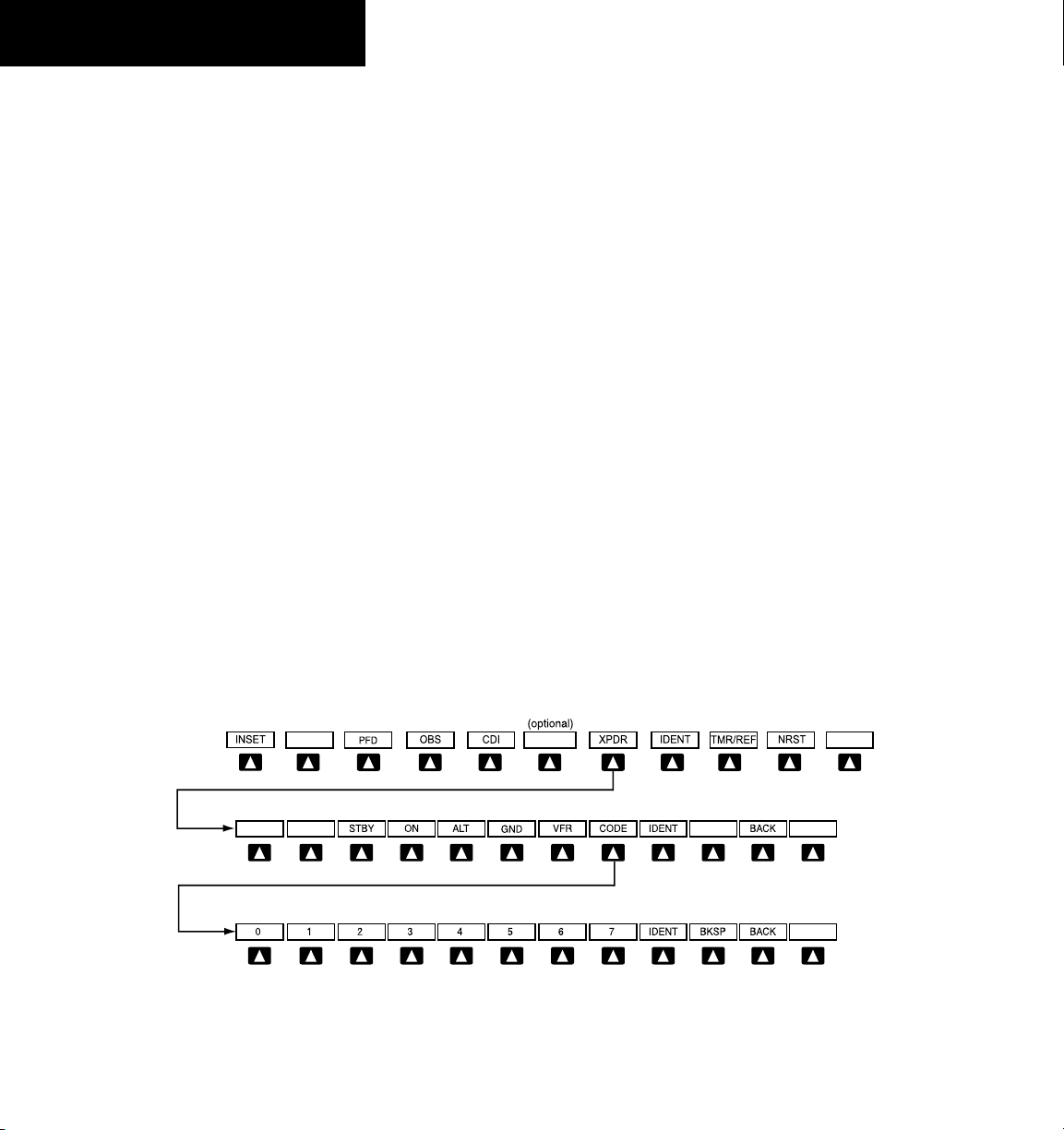
XPDR – Press to display the transponder and mode
selection softkeys.
STBY
– Press to select standby mode.
ON
– Press to select Mode A.
ALT
– Press to select altitude mode (Mode C).
GND
– Manually selects Ground Mode. The
transponder does not allow Mode A and
Mode C replies, but it does permit acquisition
squitter and replies to discretely addressed
Mode S interrogations.
VFR
– Press to automatically enter the VFR code
(1200 in the U.S.A. only).
CODE
– Press to display transponder code selection
softkeys 0-7.
0 through 7
– Press numbers to enter code.
BKSP
– Press to remove numbers entered one
at a time.
BACK
– Press to return to the previous level
softkeys.
IDENT
– Press to provide special aircraft
position identification to Air Traffic Control
(ATC) when the transponder is set to ON or
ALT.
IDENT
– Press to provide special aircraft position
identification to Air Traffic Control (ATC)
when the transponder is set to ON or ALT.
BACK
– Press to return to the previous level
softkeys.
IDENT – Press to provide special aircraft position
identification to Air Traffic Control (ATC) when
the transponder is set to ON or ALT.
TMR/REF – Press to display the Timer/References
Window.
NRST – Press to display the Nearest Airports
Window.
ALERTS – Press to display the Alerts Window.
1-6
Figure 1-5 Transponder Softkeys
Garmin G1000 Cockpit Reference Guide for the Piper PA32
Page 19
SECTION 1
MAP
DCLTR
TRAFFIC
TOPO
TERRAIN
DCLTR-2
DCLTR-3
DCLTR-1
BACK
Press to return to the
top softkey level
NEXRAD
XM LTNG
(optional)
(optional)
ENGINE
Press the ENGINE Softkey to
return to the default page level
ENGINE
ASSIST
DEC FUEL
INC FUEL
RST FUEL
STRMSCP
(optional)
(The ASSIST Softkey
is not available on
turbocharged aircraft)
ENGINE
LEAN SYSTEM
BACK
ENGINE
LEAN SYSTEM
BACK
CYL SLCT
ASSIST
ENGINE
LEAN
SYSTEM
BACK
DEC FUEL
INC FUEL
RST FUEL
(The ASSIST Softkey
is not available on
turbocharged aircraft)
In reversionary mode, the following EIS selections are available.
AIRWAYS
AIRWY LO
AIRWAY HI
AIRWY ON
SHW CHRT
(optional)
(Default softkey
is dependent on
the selection made
in the map setup
options)
SYSTEM OVERVIEW
1.3 MFD SOFTKEYS
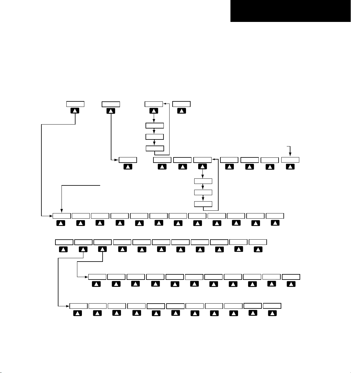
ENGINE – Pressing this softkey makes available the full
size Engine Display and functions. Refer to the Engine
Indication System section. Note in Figure 1-6, when in
Reversionary Mode, EIS display selections change.
MAP – Pressing this softkey enables the following
softkeys:
TRAFFIC – Pressing this softkey displays/removes
Traffic on the Navigation Map.
TOPO – Pressing this softkey displays or removes
topographic information on the Navigation Map.
TERRAIN – Pressing this softkey displays/removes
terrain and obstacle data on the Navigation Map.
Garmin G1000 Cockpit Reference Guide for the Piper PA32
Figure 1-6 MFD Softkeys
1-7
Page 20

SECTION 1
SYSTEM OVERVIEW
AIRWAYS – Pressing this softkey displays/removes
airways information. The default is dependant on
map setup option seledcted. Pressing cycles through
all airways displayed (AIRWY ON), low altitude
airways only (AIRWY LO), and high altitude airways
only (AIRWY HI).
STRMSCP (optional) – Pressing this softkey displays/
removes Stormscope lightning data on the Navigation
Map.
NEXRAD (optional) – Pressing this softkey displays/
removes precipitation data on the Navigation Map.
XM LTNG (optional) – Pressing this softkey displays/
removes XM Radio lightning data on the Navigation
Map.
BACK – Pressing this softkey displays the ENGINE and
MAP top level softkeys.
DCLTR (declutter) – Pressing this softkey removes map
information in three levels.
SHW CHRT – When available, displays optional airport
and terminal procedures charts.
1.4 MFD PAGE GROUPS
1)
Turn the large
group is selected.
2)
Turn the small
the group. See Figure 1-7.
FMS
Knob until the desired page
FMS
Knob to select pages within
1.5 VERTICAL NAVIGATION
One of two altitude sources is used by the G1000 when
giving vertical navigation guidance. WAAS GPS altitude is
used when giving guidance for a WAAS approach. Baro
corrected altitude is used when vertical guidance is given
in all other situations.
The G1000 system can use altitude constraints
associated with lateral waypoints to give guidance for
vertical navigation. These altitudes are, depending on the
specific instance, entered by the pilot or retrieved from the
published altitudes in the navigation database.
The navigation database only contains altitudes
for procedures that call for “Cross at” altitudes. If the
procedure states “Expect to cross at,” then the altitude will
not be in the database. In this case the altitude may be
entered manually.
NOTE: All arrival procedure altitudes contained in
the navigation database are for turbojet aircraft only.
Alter or enter altitudes as desired to comply with the
ATC clearance.
When activating or loading an arrival or approach
procedure into an active flight plan, the VNV ‘ALT’ fields
will be populated with any altitudes that can be retrieved
from the navigation database.
1-8
Auxiliary Page Group
Waypoint Page Group
Map Page Group
Nearest Group
Number of Pages in Current
Group
Figure 1-7 Page Group Icon
Garmin G1000 Cockpit Reference Guide for the Piper PA32
Selected Page
Page 21

SECTION 1
SYSTEM OVERVIEW
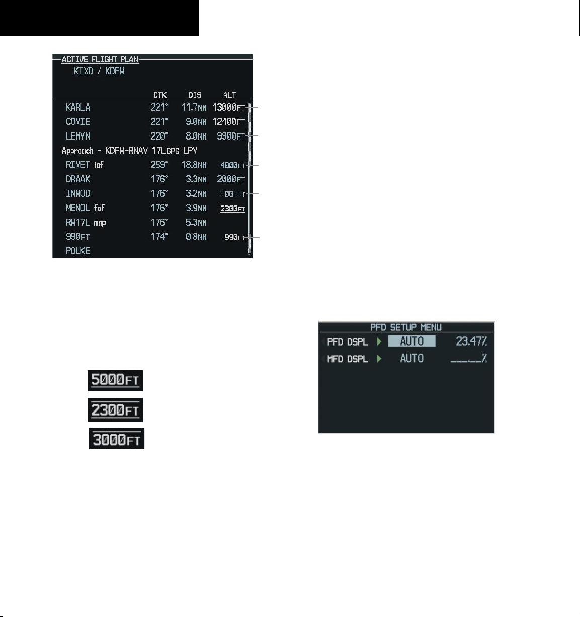
Since altitudes loaded with an arrival procedure are
published only for turbojet aircraft, the altitudes are
displayed as white text indicating that the altitudes are
displayed for reference only. An arrival waypoint altitude
may be used (or “designated”) as is, or changed to a
different altitude. An altitude is designated by pressing the
FMS Knob and turning the large FMS Knob to place the
cursor on the desired altitude and pressing the ENT Key or
entering a different value and pressing the ENT Key. The
altitude will now be displayed as blue text, indicating that
the altitude is now designated to give vertical speed and
deviation guidance.
Approach waypoint altitude constraints are designated
in the same way as previously described for arrivals. These
altitudes will also be displayed as blue text after being
designated for use. Waypoint altitude constraints may
be designated up to, but not including the FAF. The FAF
will always be a “reference only” altitude and cannot be
designated, unless the selected approach does not provide
vertical guidance. In this case, the FAF altitude can be
designated.
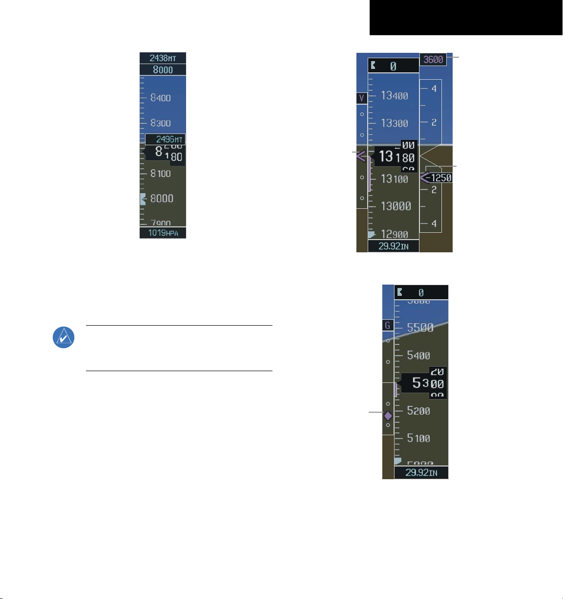
White Text Light Blue Text Light Blue Subdued Text
Altitudes that have been designated for use in vertical
guidance may also be made “non-designated” by placing the
cursor over the desired altitude and pressing the CLR Key.
Other displayed altitudes may change due to re-calculations
or rendered invalid as a result of manually changing an
altitude to a non-designated altitude.
To help interpret the meanings of how the altitudes are
presented, keep the following points in mind:
• When the altitude is displayed in light blue,
the system is using that altitude (designated) to
determine vertical speed and deviation guidance.
• When the altitude is displayed in white, it is not being
used by the system (non-designated) to determine
the vertical speed and deviation guidance.
• An altitude displayed as small text is an altitude that
is published in the navigation database.
• Altitudes displayed as a light blue subdued text
cannot be used in the current vertical navigation
calculations.
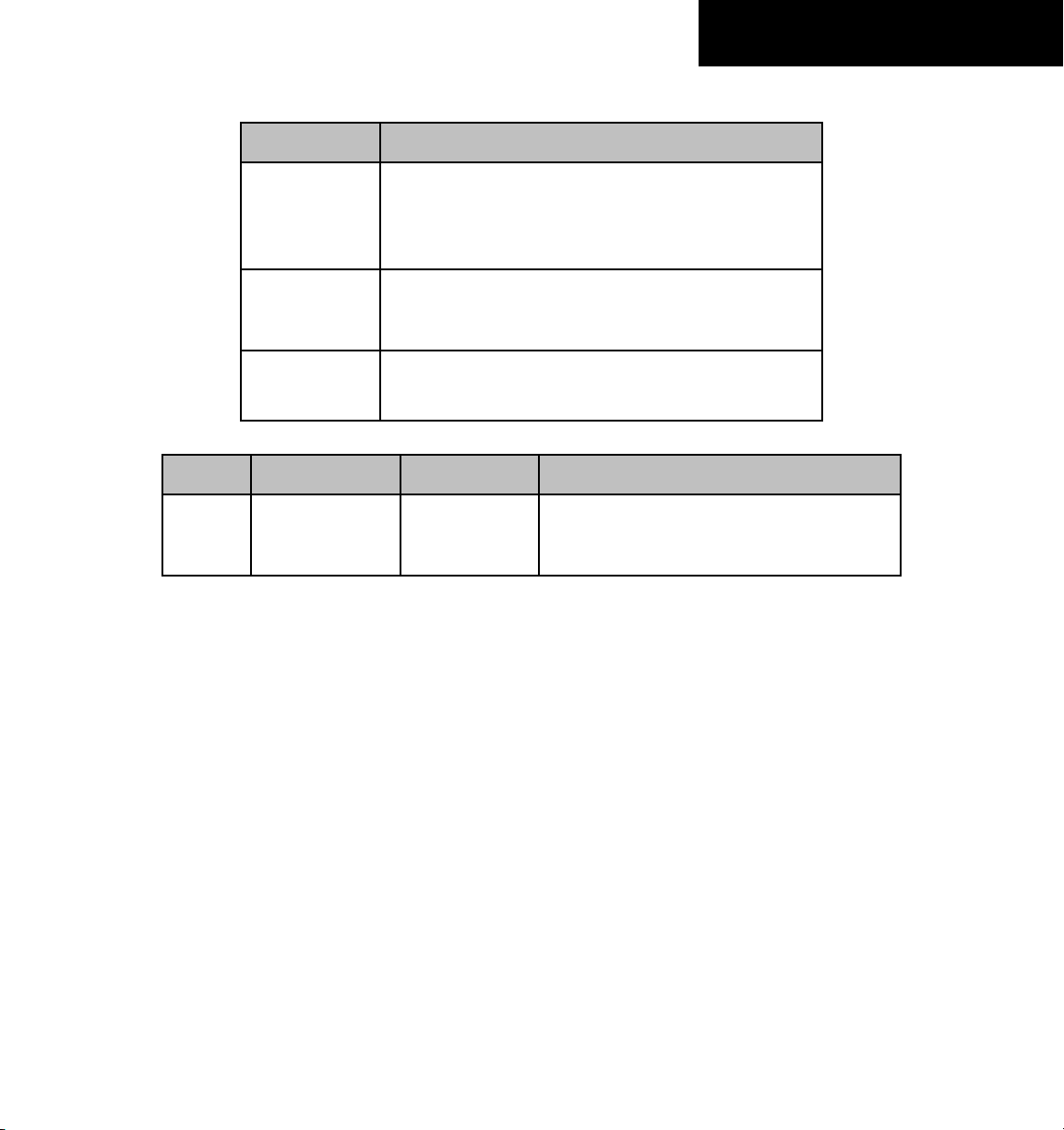
Large Text
Small Text
Altitude calculated by the system
estimating the altitude of the
aircraft as it passes over the
navigation point. This altitude
is provided as a reference and
is not designated to be used in
determining vertical speed and
deviation guidance.
Altitude is not designated to
be used in determining vertical
speed and deviation guidance.
Altitude has been retrieved from
the navigation database and is
provided as a reference.
Table 1-1 VNV Altitude Text Size and Color
Garmin G1000 Cockpit Reference Guide for the Piper PA32
Altitude has been entered by the
pilot. Altitude is designated for
use in giving vertical speed and
deviation guidance. Altitude does
not match the published altitude
in navigation database or no
published altitude exists.
Altitude is designated for use in
giving vertical speed and deviation
guidance. Altitude has been
retrieved from the navigation
database or has been entered by
the pilot and matches a published
altitude in the navigation database.
The system cannot use this altitude
in determining vertical speed and
deviation guidance.
The system cannot use this altitude
in determining vertical speed and
deviation guidance.
1-9
Page 22
SECTION 1
SYSTEM OVERVIEW
Large White
Large Light
Blue Subdued
Small White
Figure 1-8 VNV Altitudes
Some altitudes retrieved from the database have
associated restrictions indicating to stay ‘At’, ‘At or Above’,
or ‘At or Below’ a specific altitude. These restrictions are
indicated using a ‘bar’ above and/or below the appropriate
altitude as shown in Figure 1-9.
Text
Blue Text
SmallLight
Blue Text
SmallLight
Text
Text with
Altitude
Restriction
Bar
1.6 BACKLIGHTING
Manually adjust the backlight for the PFD
and MFD:
1)
Press the MENU Key on the PFD to display the
PFD Setup Menu window.
2)
Press the small FMS Knob to activate the cursor.
‘PFD DSPL > AUTO’ is now highlighted.
3)
Turn the small FMS Knob to display the
selection window.
4)
Turn the FMS Knob to select ‘MANUAL’, then
press the ENT Key.
5)
With the intensity value now highlighted, turn
the small FMS Knob to select the desired
backlighting.
6)
Turn the large FMS Knob to highlight ‘MFD DSPL
> AUTO’ and repeat steps 3 through 5.
1-10
Stay AT or ABOVE 5,000 ft
Stay AT 2,300 ft
Stay AT or BELOW 3,000 ft
Figure 1-9
Altitude Restrictions
See Section 7 - Navigation, for a sample flight plan
which further illustrates vertical navigation in more
detail.
Garmin G1000 Cockpit Reference Guide for the Piper PA32
Figure 1-10 PFD Setup Menu Window
1.7 DATABASE UPDATES
The G1000 system uses Secure Digital (SD) cards to
load and store various types of data. For basic flight operations, SD cards are required for database storage as well
as Jeppesen aviation and ChartView database updates.
Page 23
Jeppesen Aviation Database
NOTE: After the aviation database is installed,
the card may be removed after loading the
update to each LRU.
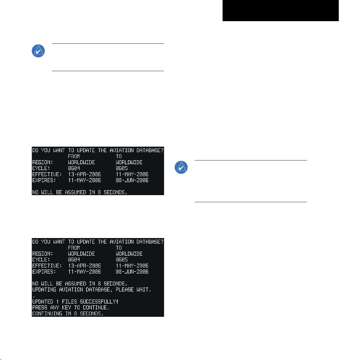
Updating the Jeppesen aviation database:
1)
With the G1000 System OFF, insert the SD card
containing the aviation database update into the
top card slot of the PFD to be updated (Label of
SD card facing left).
2)
Turn the G1000 System ON. A prompt similar to
the following is displayed in the upper left corner
of the PFD:
Figure 1-11 Database Update Prompt
3)
Press the ENT Key to start the database update.
A prompt similar to the following is displayed:
SECTION 1
SYSTEM OVERVIEW
4)
After the update completes, the PFD starts in
normal mode.
5)
Turn the G1000 System OFF and remove the SD
card.
6)
Repeat steps 1 through 4 for the MFD. The MFD
and PFD databases are now updated. Remove
the SD card when finished.
7)
Verify that the correct update cycle is loaded
during startup of the MFD.
Garmin Databases
Since these databases are not stored internally in the
MFD or PFD, a Supplemental Data Card containing iden
tical database versions must be kept in each display unit.
NOTE: The data contained in the terrain and
obstacle databases comes from government
agencies. Garmin accurately processes and
cross-validates the data, but cannot guarantee
the accuracy and completeness of the data.
1)
Insert one SD card in the bottom card slot of
the MFD and one in the bottom card slot of the
PFD. The SD card containing the ChartView or
FliteCharts database must be inserted into the
bottom slot on the MFD.
-
Figure 1-12 Database Update Confirmation
Garmin G1000 Cockpit Reference Guide for the Piper PA32
2)
Apply power to the G1000 System. View the
MFD power-up splash screen. Check that the
databases are initialized and displayed in the
window of the splash screen. When updating the
terrain and FliteCharts databases, an ‘in progress’
message may be seen. If this message is present,
wait for the system to finish loading before
verifying the correct databases are initialized,
then proceed to step 3.
1-11
Page 24

SECTION 1
SYSTEM OVERVIEW
Figure 1-13 Power-Up Splash Screen Window
3)
Acknowledge the Power-up Page agreement by
pressing the
4)
At the MAP – NAVIGATION MAP Page, select
the
MAP
the
TOPO
(not dimmed) and other database features are
functioning.
5)
Power down the G1000.
ENT
Key or the right most softkey.
Softkey and check to make sure that
and
TERRAIN
1.8 PILOT PROFILES
Creating a Profile
1)
Select the AUX - System Setup Page.
2)
Press the FMS Knob to activate the cursor.
3)
Turn the large FMS Knob to highlight ‘CREATE’
in the Pilot Profile Box.
4)
Press the ENT Key. A ‘Create Profile’ window is
displayed.
Softkeys are available
5)
Use the FMS Knob to enter a profile name
6)
Press the ENT Key.
7)
In the next field, use the small FMS Knob to select
the desired settings upon which to base the new
profile.
8)
Press the ENT Key.
9)
With ‘CREATE’ highlighted, press the ENT Key to
create the profile.
Selecting a Profile
1)
Select the AUX - System Setup Page.
2)
Press the FMS Knob to activate the cursor.
3)
Turn the large FMS Knob to highlight the active
profile field in the Pilot Profile Box.
4)
Turn the small FMS Knob to display the pilot
profile list and highlight the desired profile.
5)
Press the ENT Key. The G1000 loads and displays
the system settings for the selected profile.
Renaming a Profile
1)
Select the AUX - System Setup Page.
2)
Press the FMS Knob to activate the cursor.
3)
Turn the large FMS Knob to highlight ‘RENAME’
in the Pilot Profile Box.
4)
Press the ENT Key.
5)
In the ‘Rename Profile’ window, turn the FMS
Knob to select the profile to rename.
6)
Press the ENT Key.
7)
Use the FMS Knob to enter a new profile name
up to 16 characters.
8)
Press the ENT Key.
9)
With ‘RENAME’ highlighted, press the ENT
Key.
1-12
Garmin G1000 Cockpit Reference Guide for the Piper PA32
Page 25

Deleting a Profile
1)
Select the AUX - System Setup Page.
2)
Press the FMS Knob to activate the cursor.
3)
Turn the large FMS Knob to highlight ‘DELETE’
in the Pilot Profile Box.
4)
Press the ENT Key.
5)
In the ‘Delete Profile’ window, turn the FMS Knob
to select the profile to be deleted.
6)
Press the ENT Key.
7)
With ‘DELETE’ highlighted, press the ENT Key.
SECTION 1
SYSTEM OVERVIEW
Garmin G1000 Cockpit Reference Guide for the Piper PA32
1-13
Page 26

SECTION 1
SYSTEM OVERVIEW
Blank Page
1-14
Garmin G1000 Cockpit Reference Guide for the Piper PA32
Page 27
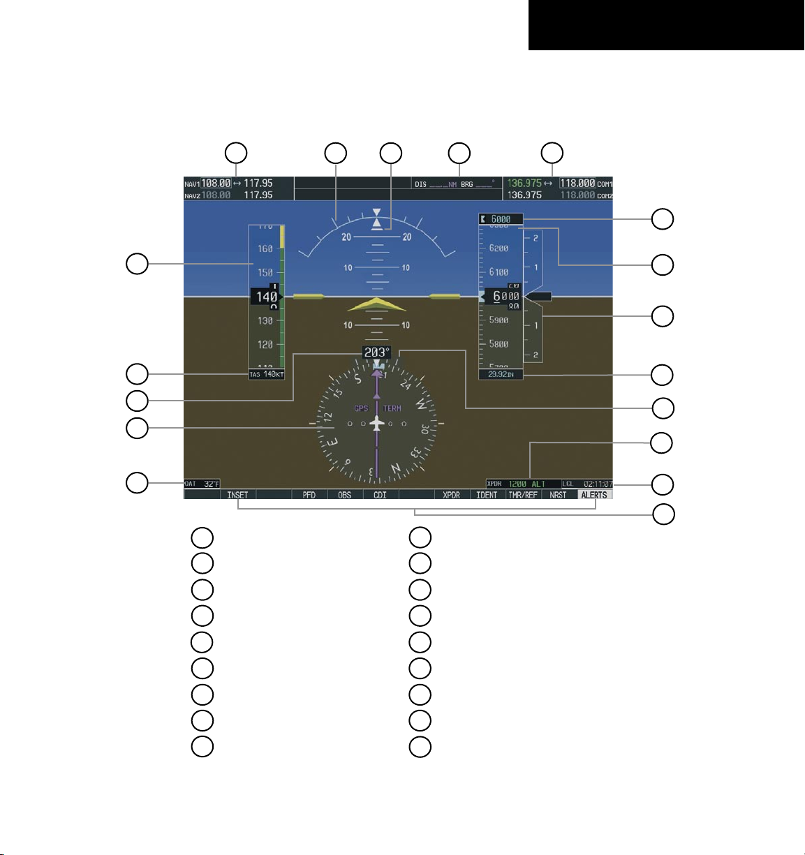
SECTION 2: FLIGHT INSTRUMENTS
The following discussions pertain to the Primary Flight Display, unless otherwise indicated.
SECTION 2
FLIGHT INSTRUMENTS
1
2
3
4
5
6
1
NAV Frequency Box
2
Airspeed Indicator
18
17
16
10
Turn Rate Indicator
11
Barometric Setting Box
15
14
13
12
11
10
9
8
7
3
True Airspeed/Mach Box
4
Heading Box
5
Horizontal Situation Indicator
6
Outside Air Temperature Box
7
Softkeys
8
System Time Box
9
Transponder Status Box
Figure 2-1 Default PFD Information
Garmin G1000 Cockpit Reference Guide for the Piper PA32
12
Vertical Speed Indicator
13
Altimeter
14
Altitude Reference Box
15
COM Frequency Box
16
Navigation Status Box
17
Slip/Skid Indicator
18
Attitude Indicator
2-1
Page 28
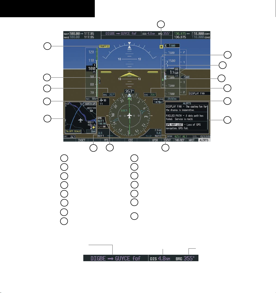
SECTION 2
FLIGHT INSTRUMENTS
1
15
14
13
2
3
4
5
6
1
Traffic Annunciation
2
Vspeed References
3
Selected Heading Box
4
Wind Data Window
5
Inset Map
6
BRG1 Information Window
7
DME Information Window
8
BRG2 Information Window
7
9
Alerts Window
10
Barometric Minimums Box
11
Selected Course Box
12
Altitude Reference Bug
13
Barometric Minimums Bug
14
Vertical Deviation/Glidepath (WAAS
enabled systems only)/Glidesope Indicator
15
Marker Beacon Annunciation
8
12
11
10
9
2-2
Active Flight Plan Leg
Garmin G1000 Cockpit Reference Guide for the Piper PA32
Figure 2-2 Additional PFD Information
Distance to Next
Waypoint
Figure 2-3 PFD Navigation Status Box
Bearing to Next
Waypoint
Page 29
SECTION 2
FLIGHT INSTRUMENTS
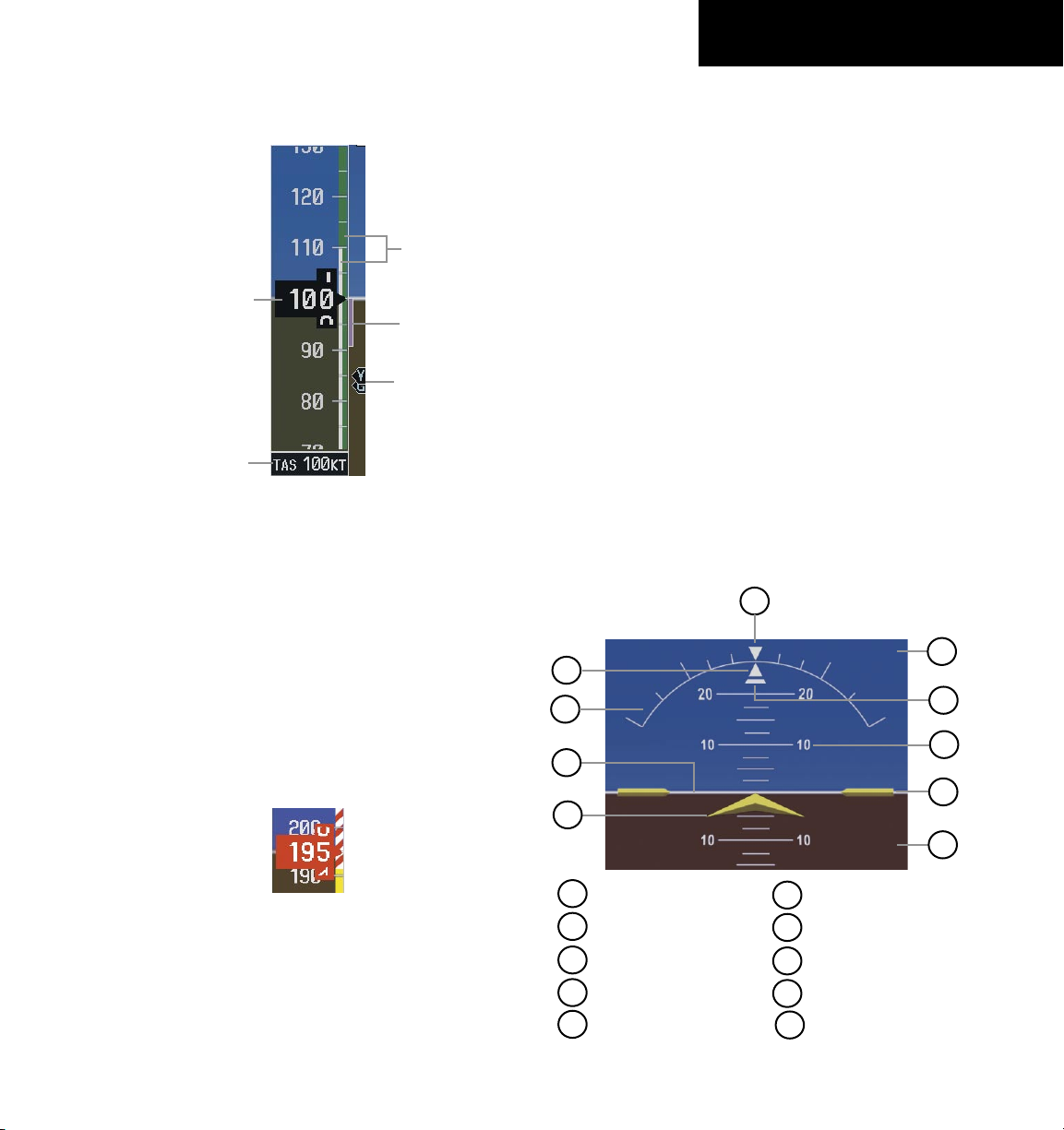
2.1 AIRSPEED INDICATOR
Speed
Ranges
Actual
Airspeed
True Airspeed
Box
Figure 2-4 Airspeed Indicator
Speed Indication
The numeric labels and major tick marks on the
moving tape are marked at intervals of 10 knots. Minor
tick marks are at intervals of 5 knots. Speed indication
starts at 20 knots. High speed awareness is represented
by a red and white ‘barber pole’. If the airspeed pointer
reaches the yellow band, or the trend vector reaches the
barber pole, the digits in the pointer turn yellow. If the
airspeed pointer reaches the ‘barber pole’, the pointer
turns red (refer to Figure 2-5).
Airspeed
Trend
Vector
Vspeed
References
Airspeed Trend Vector
The end of the trend vector displays approximately
what the airspeed will be in 6 seconds if the current rate
of acceleration/deceleration is maintained.
Vspeed References
Vspeeds are set using the TMR/REF Softkey. When
active (ON), the Vspeeds are displayed at their respective
locations to the right of the airspeed scale.
True Airspeed Box
The True Airspeed box is located below the Airspeed
indicator and displays the true airspeed in knots.
2.2 ATTITUDE INDICATOR
The Slip/Skid Indicator is located under the roll pointer
and moves laterally away from the pointer to indicate
lateral acceleration. One Slip/Skid indicator displacement
is equal to one ball displacement when compared to a
traditional slip/skid indicator.
10
9
1
2
3
4
8
7
6
5
Figure 2-5 Red Pointer
Low speed awareness is represented by a red range.
Refer to the Pilot’s Operating Handbook (POH) for speed
criteria.
Garmin G1000 Cockpit Reference Guide for the Piper PA32
1
Roll Pointer
2
Roll Scale
3
Horizon Line
4
Aircraft Symbol
5
Land Representation
Figure 2-6 Attitude Indicator
6
Aircraft Wing Tips
7
Pitch Scale
8
Slip/Skid Indicator
9
Sky Representation
10
Roll Scale Zero
2-3
Page 30
SECTION 2
FLIGHT INSTRUMENTS
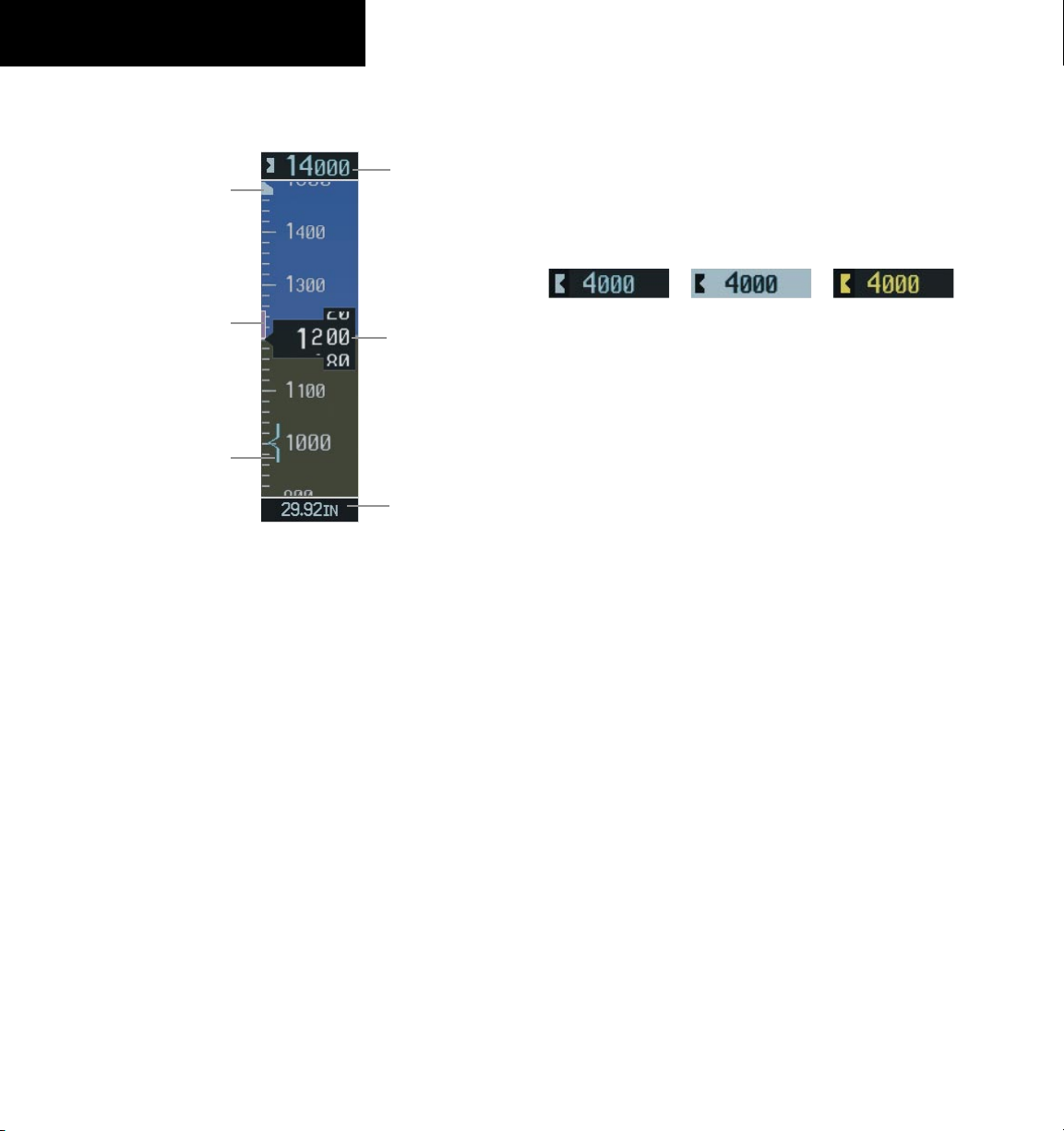
2.3 ALTIMETER
Altitude
Altitude
Reference
Bug
Altitude
Trend
Vector
Barometric
Altitude
Minimums Bug
Figure 2-7 Altimeter
Altitude Reference Bug
The Altitude Reference Bug is displayed at the Selected
Altitude or the edge of the tape (whichever is closer to the
current altitude) to provide increased altitude awareness
and to set the desired hold altitude for the autopilot.
Set the Altitude Reference Bug:
Turn the
Bug. The small
the large
altitude also appears in the Altitude Reference
Box above the Altimeter.
ALT
Knobs to set the Altitude Reference
ALT
Knob sets the hundreds and
ALT
Knob sets the thousands. This
Reference
Box
Current
Altitude
Barometric
Setting
Box
Barometric Setting Box
Tur
n the BARO Knob to select the desired setting.
Altitude Alerting
Within 1000 ft
Figure 2-8 Altitude Alerting Visual Annunciations
Within 200 ft
Visual annunciations appear in the Altitude Reference
Box. Whenever the setting is changed, the Altitude
Alerter is reset. The Altitude Alerter is independent of the
Automatic Flight Control System.
Deviation of ±200 ft
Metric Display
Display altitude in meters and barometric
pressure in hectopascals:
1)
Press the PFD Softkey to display the second level
softkeys.
2)
Press the ALT UNIT Softkey.
3)
Press the METRIC Softkey to display altitude in
meters.
4)
Press the HPA Softkey to display the barometric
setting in hectopascals. Press the IN Softkey
to display the barometric setting in inches of
mercury.
5)
Press the BACK Softkey to return to the previous
level softkeys.
2-4
Altitude Trend Vector
The end of the trend vector displays approximately
what the altitude will be in 6 seconds if the current rate of
vertical speed is maintained.
Garmin G1000 Cockpit Reference Guide for the Piper PA32
Page 31
Vertical
Deviation
Indicator
SECTION 2
FLIGHT INSTRUMENTS
VNV
Target
Altitude
Required
Vertical
Speed
Figure 2-9 Altimeter (Metric)
2.4 VERTICAL DEVIATION/GLIDEPATH/
GLIDESLOPE INDICATOR
NOTE: VNV altitudes displayed on the Active
Flightplan Page must be designated for use in
vertical guidance.
The Vertical Deviation and Required Vertical Speed
Indicators appear when vertical guidance is being given
prior to executing an approach (see Figure 2-10). In
systems that are WAAS enabled, the Glidepath Indicator
appears at a point prior to the FAF when executing an
or LNAV+V approach (see Figure 2-11).
LPV
Figure 2-10 Vertical Deviation Indications
Glidepath
Indicator
Figure 2-11 Glidepath Indicator
Garmin G1000 Cockpit Reference Guide for the Piper PA32
2-5
Page 32

SECTION 2
FLIGHT INSTRUMENTS
The Glideslope Indicator appears when an ILS approach
has been activated and an ILS is tuned in the active NAV
receiver field (see Figure 2-12).
Marker Beacon
Annunciation
Glideslope
Indicator
Figure 2-12 Glideslope Indicator
2.5 MARKER BEACON ANNUNCIATIONS
Outer Marker Middle Marker Inner Marker
2.6 VERTICAL SPEED INDICATOR
Vertical Speed Pointer
Figure 2-14 Vertical Speed Indicator
The actual vertical speed is displayed inside the
pointer.
2.7 BAROMETRIC ALTITUDE MINIMUMS
The desired barometric altitude minimums can be set in
the Timer/References Window. The altitude ranges from 0
to 16,000 feet in 10-foot increments. The minimums are
reset anytime the power is cycled.
2-6
Altimeter
Figure 2-13 Marker Beacon Annunciations
Garmin G1000 Cockpit Reference Guide for the Piper PA32
Figure 2-15 Barometric Minimum Descent Altitude Settings
The desired barometric minimum descent altitude
(MDA, or Decision Height, DH) can be set in the Timer/
References Window.
Visual annunciations alert the pilot when approaching
the MDA:
• When the aircraft altitude descends to within 2500
feet of the MDA setting, the Barometric Minimum
Box appears with the altitude in light blue text.
Page 33

SECTION 2
FLIGHT INSTRUMENTS
The bug appears on the tape in light blue once in
range.
• When the aircraft passes through 100 feet of the
MDA, the bug and text turn white.
• Once the aircraft descends past the MDA, the bug
and text turn yellow and the aural alert, “Minimums
Minimums”, is generated.
Alerting is inhibited while the aircraft is on the ground.
If the aircraft climbs after having reached the MDA, once it
reaches 50 feet above the
Barometric
Minimum Bug
Barometric
Minimum Box
MDA, alerting is disabled.
Within 2500 ft
Altitude Reached
Within 100 ft
2)
Turn the small
barometric altitude minimums and press the
FMS
Knob to select the desired
ENT
Key. The ON/OFF field is now highlighted.
3)
Turn the small
FMS
Knob in the direction of the
green arrowhead.
2.8 WIND DATA
When the window is selected for display, but wind
information is invalid or unavailable, the window shows
“NO WIND DATA”. Wind data can be displayed in three
different ways:
• Longitudinal and lateral components (Option 1)
• Total wind direction and speed (Option 2)
• Total direction with head and crosswind speed
components (Option 3)
Option 1 Option 2
Option 3 No Data
Figure 2-16 Barometric Minimum Descent Altitude
Alerting Visual Annunciations
Set the barometric altitude minimums:
1)
From the Timer References Window, turn the large
FMS
Knob to highlight the BARO MIN field.
Garmin G1000 Cockpit Reference Guide for the Piper PA32
Displaying wind data:
1)
Press the PFD Softkey.
2)
Press the WIND Softkey to display wind data
below the Selected Heading.
3)
Press one of the OPTN softkeys to change how
wind data is displayed.
4)
To remove the Wind Data Window, press the OFF
Softkey.
Figure 2-17 Wind Data Window
2-7
Page 34

SECTION 2
FLIGHT INSTRUMENTS
2.9 HORIZONTAL SITUATION INDICATOR (HSI)
15
14
1
2
3
4
5
6
7
1
Turn Rate Indicator
2
Ground Track Bug
3
Lateral Deviation Scale
4
Navigation Source
5
Aircraft Symbol
6
Course Deviation Indicator
7
Rotating Compass Rose
8
OBS Mode
9
TO/FROM Indicator
10
Heading Bug
11
Course Pointer
12
Flight Phase
13
Turn Rate and Heading Trend Vector
14
Heading
15
Lubber Line
Figure 2-18 Horizontal Situation Indicator
13
12
11
10
9
8
Turn Rate Indicator and Heading Trend Vector
Tick marks to the left and right of the lubber line
denote half-standard and standard turn rates. A magenta
turn rate trend vector shows the current turn rate. The
end of the trend vector gives the heading predicted in six
seconds, based on the present turn rate. At rates greater
than 4 deg/sec, an arrowhead appears at the end of the
magenta trend vector and the prediction is no longer
valid.
Half-Standard Turn
Rate Tick Mark
Standard Turn
Rate Tick Mark
Figure 2-19 Turn Rate Indicator and Trend Vector
Figure 2-20 Standard-Rate Turn Indication
Turn Rate
Trend Vector
(rate > 4
deg/sec)
Turn Rate
Trend Vector
(standard rate)
Course Pointer
The Course Pointer is a single line arrow (GPS, VOR1
and LOC1) or double line arrow (VOR2 and LOC2) which
points in the direction of the set course.
Figure 2-21 Course Pointer
2-8
Garmin G1000 Cockpit Reference Guide for the Piper PA32
Page 35

Course Deviation Indicator (CDI)
The CDI scale automatically adjusts to the current
phase of flight as seen in Figure 2-22. Scaling may be
selected manually from the MFD System Setup Page.
Flight Phase Automatic CDI Full-scale
Deflection
Departure (DRPT) 0.3 nm
Terminal (TERM)
Enroute (ENR) 2.0 nm
Oceanic (OCN) 2.0 nm
1.0 nm
SECTION 2
FLIGHT INSTRUMENTS
Figure 2-23 Typical LNAV and LNAV+V Approach CDI Scaling
Approach (LNAV)
Approach (LNAV+V)
Approach (LNAV/
VNAV)
Approach (LPV)
Missed Approach
1.0 nm decreasing to 350 feet
depending on variables (see Figure
2-23)
1.0 nm decreasing to a specified
course width, then 0.3 nm,
depending on variables (see Figure
2-24)
0.3 nm
Figure 2-22 Phases of Flight/CDI Scaling
Figure 2-24 Typical LNAV/VNAV and LPV Approach CDI Scaling
Garmin G1000 Cockpit Reference Guide for the Piper PA32
2-9
Page 36

SECTION 2
FLIGHT INSTRUMENTS
Bearing Pointers and Information Windows
Pressing the PFD Softkey provides access to the BRG1
and BRG2 Softkeys. The BRG1 Pointer is a single line
pointer. The BRG2 Pointer is a double line pointer.
Bearing 1
Pointer
Bearing 1
Information
Window
Figure 2-25 HSI with Bearing Information
Distance to
Bearing Source
Waypoint
Identifier
Bearing
Source
Figure 2-26 BRG1 Information Window
Bearing 2
Pointer
Pointer
Icon
Distance to
Bearing Source
CDI
Bearing 2
Information
Window
Waypoint
Identifier
DME (optional)
To display the DME Information Window, press the
PFD Softkey followed by the DME Softkey.
Figure 2-28 DME Information Window
Navigation Source
Change navigation sources:
1)
Press the CDI Softkey to change from GPS to
VOR1/LOC1.
2)
Press the CDI Softkey again to change from
VOR1/LOC1 to VOR2/LOC2.
3)
Press the
GPS.
When using GPS as the navigation source, the following
may appear:
• LOI - GPS position integrity is inadequate for the
current procedure being flown. If GPS is being used
as primary navigation, and LOI is annunciated, other
means of primary navigation will be required, such
as VHF. LOI is also displayed during GPS position
initialization.
• WARN – GPS detects a position error.
• SUSP – Displayed when in OBS Mode indicating
GPS waypoint sequencing is suspended.
• DR – Navigating using Dead Reckoning due to an
error in the GPS solution.
CDI
Softkey a third time to return to
2-10
Pointer
Icon
Figure 2-27 BRG2 Information Window
Bearing
Source
Garmin G1000 Cockpit Reference Guide for the Piper PA32
Page 37

Figure 2-29 GPS LOI, GPS SUSP, LOC1 and VOR2
Enable/disable OBS Mode while navigating
with GPS:
1)
Press the OBS Softkey to select OBS Mode.
2)
Turn the CRS Knob to select the desired course
to/from the waypoint.
SECTION 2
FLIGHT INSTRUMENTS
2.10 GENERIC TIMER
Figure 2-30 Timer Status Prompts
Change the Generic Timer:
1)
Press the
FMS
Turn the
press the
highlighted.
2)
Turn the small
window. Turn the
‘DOWN’, then press the
now highlighted.
3)
Press the
timer (if the timer is counting DOWN, it must be
reset manually). Press the
Softkey to remove the window.
TMR/REF
Softkey, then turn the large
Knob to select the time field (hh/mm/ss).
FMS
Knobs to set the desired time, then
ENT
Key. The UP/DOWN field is now
FMS
Knob to display the UP/DOWN
FMS
Knob to select ‘UP’ or
ENT
Key. ‘START?’ is
ENT
Key to START, STOP, or RESET the
CLR
Key or the
TMR/REF
3)
Press the OBS Softkey again to disable OBS
Mode.
NOTE: The OBS Softkey is only displayed when
navigating an active leg using GPS.
Garmin G1000 Cockpit Reference Guide for the Piper PA32
2-11
Page 38

SECTION 2
FLIGHT INSTRUMENTS
Blank Page
2-12
Garmin G1000 Cockpit Reference Guide for the Piper PA32
Page 39

SECTION 3: ENGINE INDICATION
SYSTEM (EIS)
3.1 DEFAULT ENGINE DISPLAY
In all cases white or green indicates normal operation,
yellow indicates caution, and red indicates warning.
SECTION 3 – ENGINE
INDICATION SYSTEM (EIS)
Pressing the
ENGINE Softkey makes available the
full EIS Page, providing access to the
softkeys.
Essential Bus
Voltage
STBY ALT displayed
when standby alternator
is producing more than
than 2 amps
Figure 3-1 Default Engine Display
(Normally Aspirated)
ASSIST and fuel
Emergency
Battery
Voltage
Turbo Inlet
Temperature
Essential Bus
Voltage
Figure 3-2 Default Engine Display
Emergency
Battery
Voltage
(Turbocharged)
Garmin G1000 Cockpit Reference Guide for the Piper PA32
3-1
Page 40

SECTION 3 – ENGINE
INDICATION SYSTEM (EIS)
3.2 FULL EIS DISPLAY
NOTE: Fuel calculations do not use the aircraft
fuel quantity indicators, and are calculated from
the last entered fuel remaining (GAL REM).
Press the ENGINE Softkey to display the full size
engine display.
The following softkeys allow for adjustment of the
remaining fuel quantity.
- DEC FUEL – Allows the pilot to decrease the fuel
remaining (GAL REM) in 1-pound increments
- INC FUEL – Allows the pilot to increase the
remaining in 1-pound increments
- RST FUEL – Resets the fuel remaining to 102
gallons.
In the FUEL CALC box, fuel used (GAL USED),
endurance (ENDUR), and range (RANGE NM) are
all calculated based on the last adjustment of the fuel
remaining (GAL REM). Remaining fuel quantity does not
reset when power is cycled.
fuel
3-2
Figure 3-3 Full Engine Display
(Turbocharged)
Garmin G1000 Cockpit Reference Guide for the Piper PA32
Page 41

SECTION 3 – ENGINE
INDICATION SYSTEM (EIS)
Figure 3-4 Full Engine Display
(Normally Aspirated)
Leaning Assist (Normally Aspirated Engine Only)
1)
Press the
2)
Press the
3)
Lean the mixture until one of the cylinder’s
exhaust temperature peaks. This is indicated by
‘1st’ being displayed below the first cylinder to
peak.
4)
Continue leaning the mixture until the last of the
cylinders peaks. This is indicated by ‘Last’ being
displayed below the last peaking cylinder.
5)
Adjust the ∆peak according to the Airplane Flight
Manual.
ENGINE
ASSIST
Softkey.
Softkey.
Garmin G1000 Cockpit Reference Guide for the Piper PA32
Press the ASSIST Softkey when finished leaning to
remove the leaning function. Press the ENGINE Softkey
to exit the Engine Page and return the MFD to default
operation.
3-3
Page 42

SECTION 3 – ENGINE
INDICATION SYSTEM (EIS)
Blank Page
3-4
Garmin G1000 Cockpit Reference Guide for the Piper PA32
Page 43

SECTION 4: NAV/COM AND
TRANSPONDER
The NAV/COM controls and frequency boxes share the
same locations on the on the Primary Flight Display and
the Multi-Function Display.
SECTION 4 – NAV/COM &
TRANSPONDER
NAV
Controls
NAV Frequency Box COM Frequency Box
COM
Controls
Figure 4-1 G1000 VHF NAV/COM Controls (
Garmin G1000 Cockpit Reference Guide for the Piper PA32
PFD shown)
4-1
Page 44
SECTION 4 – NAV/COM &
TRANSPONDER
Standby NAV
Frequency Field
Frequency Field
Selected NAV
Frequency
Active NAV
Frequency Transfer Arrow
NAV Controls COM Controls
Figure 4-2 Frequency Fields
Figure 4-3 Frequency Transfer Arrow and Tuning Box
VOL/PUSH
ID Knob
VOL/PUSH
SQ Knob
Selected COM
Frequency
Tuning Box
Active COM
Frequency Field
Standby COM
Frequency Field
Tuning BoxTuning Box
4-2
Frequency Transfer Key
Dual NAV
Knob
• Turn to tune in desired
frequencies.
• Press to change tuning box
positions.
Figure 4-4 NAV/COM Controls
Garmin G1000 Cockpit Reference Guide for the Piper PA32
Dual COM
Knob
Page 45

SECTION 4 – NAV/COM &
TRANSPONDER
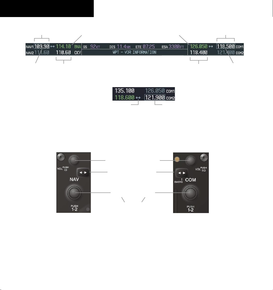
4.1 RADIO STATUS INDICATIONS
• RX – When a COM signal is received, a white ‘RX’
appears by the active COM frequency during signal
reception.
• TX – When a COM radio is transmitting, a white ‘TX’
indication appears to the right of the corresponding
COM frequency.
• ID – When the Morse code identifier is ON for a NAV
radio, a
the corresponding active NAV frequency. The Morse
code identifier can be heard if the corresponding
NAV radio is selected on the audio panel.
white ‘ID’ indication appears to the left of
Figure 4-5 Radio Status Indications
4.2 VOLUME
‘VOLUME’ is displayed in place of the associated radio
name (i.e., ‘COM1’ or ‘NAV2’) for two seconds after the
volume level is last changed. The percentage of maximum
volume is displayed in place of the standby frequency
selected by the tuning box.
4.4 QUICKLY ACTIVATING 121.500 MHZ
Pressing and holding the COM Frequency Transfer
Key for approximately two (2) seconds automatically tunes
the selected COM radio to the emergency frequency.
4.5 OPTIONAL NAV RADIOS
DME Radio (optional)
The DME Tuning Window is displayed by pressing the
DME Softkey.
Figure 4-7 Radio Tuning Window
Change the DME tuning source:
1)
From the tuning window, turn the large
to highlight the DME source field.
2)
Turn the small
window. Turn the
mode and press the
FMS
Knob to display the selection
FMS
Knob to select the desired
ENT
Key.
FMS
Knob
Figure 4-6 COM Volume Level
4.3 AUTOMATIC SQUELCH
Automatic squelch can be disabled for a COM radio by
pressing the COM Knob to place the tuning box on the
desired COM’s standby frequency, then by pressing the
VOL/PUSH SQ Knob.
Garmin G1000 Cockpit Reference Guide for the Piper PA32
Figure 4-8 DME Selection Window
ADF Radio (optional)
The G1000 does not support tuning of the ADF in
PA32. ADF tuning is accomplished through the Bendix/
King KR 87 ADF Radio. ADF volume must also be
adjusted through the KR 87.
4-3
Page 46
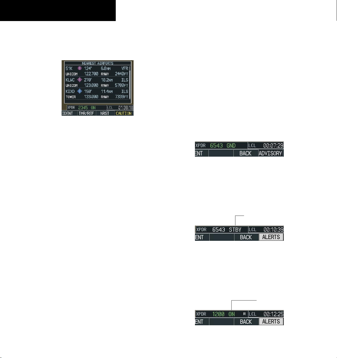
SECTION 4 – NAV/COM &
TRANSPONDER
4.6 FREQUENCY AUTO-TUNING
Auto-tuning on the PFD
Figure 4-9 Nearest Airports Window (PFD)
1)
Press the
Airports Window.
2)
Turn either
frequency.
3)
Press the
standby field of the active COM.
4)
Press the
frequency in the active field.
NAV frequencies are entered automatically in the active
NAV frequency field upon approach loading or approach
activation.
NRST
Softkey to display the Nearest
FMS
Knob to highlight the desired
ENT
Key to place the frequency in the
Frequency Transfer
Key to place the
4.7 TRANSPONDER
Mode Selection
The STBY, ON, ALT, GND, VFR, CODE, and IDENT
Softkeys can be accessed by pressing the
Ground Mode (Automatic or Manual)
GND is displayed when the aircraft is on the ground or
when the
GND Softkey is pressed. The transponder does
not allow Mode A and Mode C replies, but it does permit
acquisition squitter and replies to discretely address
Mode S interrogations.
Figure 4-10 Ground Mode
Standby Mode (Manual)
Press the
STBY Softkey. In Standby Mode, the transponder does not reply to interrogations, but new codes
can be entered.
STBY Mode (White
Code Number and
XPDR Softkey.
Mode)
4-4
Auto-tuning on the MFD
Auto-tuning on the MFD is done in much the same way
as on the PFD. Use the FMS Knobs to select the desired
frequency on any of the information pages. Pressing the
ENT Key then loads the selected frequency in the tuning
box as a standby frequency.
Garmin G1000 Cockpit Reference Guide for the Piper PA32
Figure 4-11 Standby Mode
Manual ON Mode
Press the
ON Softkey. ON Mode generates Mode A
and Mode S replies, but Mode C altitude reporting is inhibited.
ON Mode
(No Altitude
Reporting)
Figure 4-12 ON Mode
Page 47
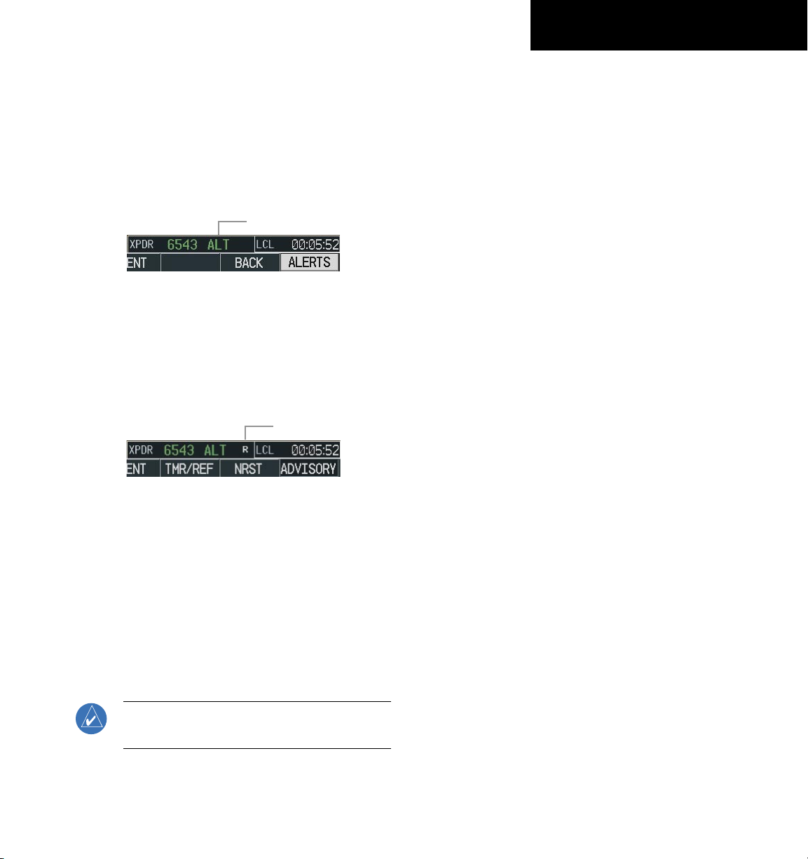
SECTION 4 – NAV/COM &
TRANSPONDER
Altitude Mode (Automatic or Manual)
Altitude Mode is automatically selected when the air
craft becomes airborne. Altitude Mode may also be selected manually by pressing the ALT Softkey.
All transponder replies requesting altitude information
are provided with pressure altitude information.
ALT Mode (Mode C
Altitude Reporting)
Figure 4-13 Altitude Mode
Reply Status
When the transponder sends replies to interrogations,
an “R” indication appears momentarily in the reply status
field.
Reply
Indication
Figure 4-14 Reply Indication
Enter Code Using Softkeys
1)
Press the
XPDR
Softkey to display the
transponder Mode Selection softkeys.
2)
Press the
CODE
Softkey to display the
transponder Code Selection softkeys, which
includes the digit softkeys.
3)
Press the appropriate digit softkeys to enter
the code in the four-digit code field of the
Transponder Status Box. When the last digit
is entered, the transponder code becomes
active.
When entering a code, press the
BKSP
as needed to back up and change code
digits.
Enter Code Using the FMS Knob
1)
Press the
XPDR
Softkey to display the
transponder Mode Selection softkeys.
2)
Press the
CODE
Softkey to display the
transponder Code Selection softkeys, which
includes the digit softkeys.
Softkey
Code Selection
VFR Code Selection
1)
Press the
transponder Mode Selection softkeys.
2)
Press the
Pressing the
previous identification code.
NOTE: The pre-programmed VFR Code is set at
the factory to 1200.
XPDR
Softkey to display the
VFR
Softkey to enter the VFR code.
VFR
Softkey again restores the
Garmin G1000 Cockpit Reference Guide for the Piper PA32
3)
Turn the small FMS Knob to enter the first two
digits.
4)
Turn the large FMS Knob to place the cursor
in position to change the second two digits.
5)
Turn the small FMS Knob to enter the second
two digits.
6)
Press the ENT Key to activate the code
immediately, or wait 10 seconds and the code
will become active.
4-5
Page 48
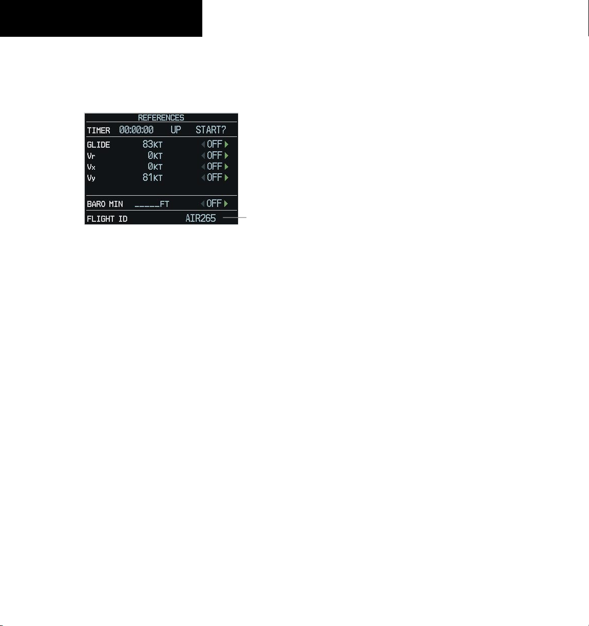
SECTION 4 – NAV/COM &
TRANSPONDER
Flight ID Reporting
If so configured, the Flight ID may be entered in the
Timer/Reference Window.
Figure 4-15 Timer/References Window
1)
Press the
References Window.
2)
Turn the large FMS Knob to place the cursor in
the Flight ID field.
TMR/REF
Softkey to display the Timer/
Flight ID
PFD Entry
4-6
3)
Turn the small FMS Knob to enter the desired
first character.
4)
Turn the large FMS knob to place the cursor in
the next desired field.
5)
Turn the small FMS Knob to enter the next
desired character.
6)
Repeat steps 4 and 5 until the desired Flight ID
is entered.
7)
Press the ENT Key. ‘updating’ will be displayed
as the Flight ID is loaded into the system.
Garmin G1000 Cockpit Reference Guide for the Piper PA32
Page 49

SECTION 5: AUDIO PANEL
SECTION 5 – AUDIO PANEL
(COM3 MIC is unavailable)
Transmitters
Split COM
Passenger Address
Marker Beacon/Mute
Aircraft Navigation Radio Audio
(AUX unavailable)
Manual Squelch
Received Audio
(COM 3 is unavailable)
Telephone (Unavailable)
Speaker
Marker Beacon Signal Sensitivity
Aircraft Navigation Radio Audio
Digital Clearance Recorder Play Key
ICS Isolation
VOL/SQ
Volume/Squelch
VOL Annunciation
Figure 5-1 Audio Panel Controls
Garmin G1000 Cockpit Reference Guide for the Piper PA32
SQ Annunciation
Reversionary Mode
5-1
Page 50

SECTION 5 – AUDIO PANEL
5.1 COM RADIO SELECTION
Pressing the COM1 MIC or COM2 MIC Key selects
the active transmitter (i.e., microphone). The associated
receiver audio (COM1 or COM2) also becomes selected
when the COM MIC Key is pressed.
Figure 5-2 Transceivers
5.2 SPLIT COM FUNCTION
NOTE: Split COM performance is affected by the
distance between the antennas and the separation of the tuned frequencies.
In this mode, both the pilot and the copilot can transmit
simultaneously over separate radios. The pilot can still
monitor NAV1, NAV2, and MKR audio as selected, but
the copilot is only able to monitor COM2.
5.3 MARKER BEACON RECEIVER
The marker beacon receiver is always on. Only the
marker beacon audio can be turned off. Figure 5-4 shows
the marker beacon annunciators on the PFD.
When the
annunciator is lit and the audio tone can be heard over
the speaker or headsets during marker beacon reception.
When the tone is active, pressing the MKR/MUTE
Key once mutes the audio but does not affect the marker
annunciator. The audio returns when the next marker
signal is received.
To turn off the marker beacon audio, press the
MUTE Key once when there is no marker indication
present, or press twice when an indication is present. The
key annunciator will be extinguished when the marker
beacon audio is turned off.
MKR/MUTE Key is pressed, the key
Outer Marker
Annunciator
Middle Marker
Annunciator
MKR/
5-2
Figure 5-3 Split COM Function
Pressing the COM 1/2 Key selects and deselects the
split COM function. During split COM operation, the
COM1, COM1 MIC, COM2, and COM2 MIC Keys are
active.
When the COM 1/2 Key is selected, COM1 is used by
the pilot for transmission and COM2 is used by the copilot.
The COM1 MIC annunciator blinks when the pilot’s
Push-to-talk is pressed and the COM2 MIC annunciator
blinks when the copilot’s Push-to-talk is presssed.
Garmin G1000 Cockpit Reference Guide for the Piper PA32
Inner Marker
Annunciator
Figure 5-4 Marker Beacon Annunciators on the PFD
Page 51

Marker Beacon Signal Sensitivity
The HI SENS Key can be pressed for increased marker
beacon signal sensitivity.
SECTION 5 – AUDIO PANEL
Figure 5-6 Navigation Radios
Figure 5-5 Marker Beacon
5.4 NAV RADIO AUDIO SELECTION
Pressing NAV1 or NAV2 selects and deselects the radio
source and activates the annunciator. Selected audio can
be heard over the headset and the speakers. Pushing the
PUSH/VOL/ID Knob at this time allows the navigation
facility identifer to be heard. These two keys can be
selected individually or together.
Mode
PILOT KEY
ANNUNCIATOR
ALL OFF OFF
PILOT
ON OFF
COPLT KEY
ANNUNCIATOR
5.5 INTERCOM SYSTEM (ICS) ISOLATION
Press the PILOT and/or COPLT Key to select who is
isolated from hearing the NAV/COM radios and music.
Selection scenarios are addressed in Table 5-1.
Figure 5-7 ICS Isolation
Pilot Hears Copilot Hears
Selected radios;
pilot; copilot;
passengers;
MUSIC 1
Selected radios;
pilot
Selected radios;
pilot; copilot;
passengers;
MUSIC 1
Copilot;
passengers;
MUSIC 1
Passenger
Selected radios;
pilot; copilot;
passengers;
MUSIC 2
Copilot;
passengers;
MUSIC 2
Hears
COPILOT
OFF ON
CREW ON ON
Garmin G1000 Cockpit Reference Guide for the Piper PA32
Selected radios;
pilot; passengers;
MUSIC 1
Selected radios;
pilot; copilot
Table 5-1 ICS Isolation Modes
Copilot
Selected radios;
pilot; copilot
Selected radios;
pilot; passengers;
MUSIC 2
Passengers;
MUSIC 2
5-3
Page 52

SECTION 5 – AUDIO PANEL
5.6 INTERCOM SQUELCH CONTROL
Select manual squelch for intercom audio by pressing
the MAN SQ Key to light the annunciator.
small
Pressing the
between volume and squelch adjustment by lighting VOL
or SQ respectively.
Figure 5-8 Volume/Squelch Control
VOL/SQ Knob now switches
5.7 DIGITAL CLEARANCE RECORDER
AND PLAYER
• Pressing MKR/MUTE while playing a memory block
stops play.
• Pressing the PLAY Key during play begins playing
the previously recorded memory block. Each
subsequent press of the PLAY Key will begin playing
the next previously recorded block.
If a COM input signal is detected while playing, play
is halted and the new COM input signal is recorded as the
latest block.
5-4
Each reception of primary active COM audio is
automatically recorded in a memory block. When the next
transmission is received, it is recorded in the next memory
block, and so on. Once the 2.5 minutes of recording time
has been reached, the recorder begins recording over the
stored memory blocks, starting from the oldest block.
Powering off the unit automatically clears all recorded
blocks.
Figure 5-9 Recorder/Player
• Pressing PLAY once plays the latest recorded
memory block, then returns to normal operation.
Garmin G1000 Cockpit Reference Guide for the Piper PA32
Page 53

SECTION 6: AUTOMATIC FLIGHT
CONTROL
Refer to the pilot’s guide for the installed autopilot
system.
SECTION 6 – AUTOMATIC
FLIGHT CONTROL
Garmin G1000 Cockpit Reference Guide for the Piper PA32
6-1
Page 54

SECTION 6 – AUTOMATIC
FLIGHT CONTROL
Blank Page
6-2
Garmin G1000 Cockpit Reference Guide for the Piper PA32
Page 55

SECTION 7 – NAVIGATION
SECTION 7: NAVIGATION
The majority of the following discussions pertain to
the Multi Function Display. In discussions pertaining to
the PFD, the controls are located on the PFD.
7.1 NAVIGATION MAP PAGE
WARNING: The map display should only be
used for situational awareness. Any map display
indication should be compared with approved
navigation sources.
Select the MAP Page Group
1)
Turn the large
in the page group box in the lower right of the
MFD display.
2)
Turn the small
page (indicated by a solid rectangular icon).
FMS
Knob until ‘MAP’ is highlighted
FMS
Knob to select the first MAP
7.2 DIRECT-TO NAVIGATION
Direct-to Navigation from the MFD
Identifier
Facility Name
City
VNV
Target Altitude
Map of the
Selected
Waypoint
Bearing
Direct-to
Course
Figure 7-2 MFD Direct-to Window
Enter a Direct-to Destination
1)
Press the
Direct-to ( )
Geographic
Region
VNV Target Altitude
Offset Before Selected
Map Orientation
Map Range
Distance
Activate Field
Key.
Direct-to
Figure 7-1 Navigation Map Page (Enroute)
Garmin G1000 Cockpit Reference Guide for the Piper PA32
2)
Enter the destination waypoint identifier.
3)
Press the
ENT
Key to confirm the identifier. The
‘Activate?’ field is highlighted.
4)
If no altitude constraint or course is desired, press
ENT
the
Key to activate. To enter an altitude
contraint, proceed to step 5.
5)
Turn the large
FMS
Knob to place the cursor over
the ‘VNV’ altitude field.
6)
Enter the desired altitude.
7)
Press the
ENT
Key. The option to select ‘MSL’ or
‘AGL ‘is now displayed.
8)
Turn the small
FMS
Knob to select ‘MSL’ or
‘AGL’.
7-1
Page 56

SECTION 7 – NAVIGATION
9)
Press the
ENT
Key. The cursor is placed in the
‘VNV’ offset distance field.
10)
Enter the desired target altitude offset from the
selected Direct-to.
11)
Press the
the large
ENT
Key to highlight ‘Activate?’ or turn
FMS
Knob to highlight the ‘COURSE’
field.
12)
Enter the desired course to the waypoint.
13)
Press the
14)
Press the
ENT
Key to highlight ‘ACTIVATE?’.
ENT
again to activate the Direct-to.
Select a Direct-to Destination to a Flight Plan
Waypoint
1)
While navigating an active flight plan, press the
Direct-to ( )
2)
Turn the small
Key.
FMS
Knob to the left to display a
list of flight plan waypoints as shown in Figure
7-3.
Select a Direct-to Destination to a Nearest Airport
1)
Press the
2)
Turn the small
Direct-to ( )
FMS
Knob to the left. Initially, a
Key.
flight plan waypoint list is displayed as in Figure
7-3. The list is populated only when navigating
a flight plan.
Figure 7-4 Nearest Airport List (MFD)
3)
Turn the small
FMS
Knob to the right to display
the ‘NRST’ airports to the aircraft’s current
position as shown in Figure 7-4.
4)
Turn the large
FMS
Knob to select the desired
airport.
7-2
Figure 7-3 Flight Plan Waypoint List (MFD)
3)
Turn the large
FMS
Knob to select the desired
waypoint.
4)
Press the
ENT
Key. The cursor is now displayed
on ‘ACTIVATE?’.
5)
Press
ENT
again to activate a Direct-to.
Garmin G1000 Cockpit Reference Guide for the Piper PA32
5)
Press the
ENT
Key. The cursor is now displayed
on ‘ACTIVATE?’.
6)
Press
ENT
again to activate a Direct-to.
Select a Direct-to Destination to a Recently Entered
Identifier
1)
Press the
2)
Turn the small
Direct-to ( )
FMS
Knob to the left. Initially, a
Key.
flight plan waypoint list is displayed as in Figure
7-3. The list is populated only when navigating
a flight plan.
Page 57

Figure 7-5 Recently Entered Waypoints List (MFD)
3)
Turn the small
FMS
Knob to the right to display
the ‘RECENT’ waypoints as shown in Figure 7-
5.
4)
Turn the large
FMS
Knob to select the desired
airport.
5)
Press the
ENT
Key. The cursor is now displayed
on ‘ACTIVATE?’.
6)
Press
ENT
again to activate a Direct-to.
Re-center the CDI to the Destination Waypoint
ess the Direct-to
Pr
pressing the
ENT
( )
Key, followed by
Key twice. If a missed approach
point (MAP) is the current destination, the
approach will be canceled.
SECTION 7 – NAVIGATION
8)
Press the
9)
Turn the large
ENT
Key.
FMS
Knob to place the cursor in
the ‘COURSE’ field.
10)
Enter the desired course.
11)
Press the
ENT
Key. The cursor now highlights
‘ACTIVATE?’.
12)
Press the
ENT
Key again to begin navigation using
the selected destination, altitude constraint, and
course.
Canceling Direct-to Navigation
1)
2)
Press the
Press the
Direct-to ( )
MENU
Key to display the Direct-to
Key.
options menu.
3)
With ‘Cancel Direct-To NAV’ highlighted, press
the
ENT
Key. If a flight plan is still active, the
G1000 resumes navigating the flight plan along
the closest leg.
Manually Define the Active Direct-to
1)
Press the
2)
Turn the large
Direct-to ( )
FMS
Knob to highlight the ‘VNV’
Key.
altitude field.
3)
Enter the desired altitude.
4)
Press the
ENT
Key. The option to select ‘MSL’ or
‘AGL’ is now displayed.
5)
Turn the small
FMS
Knob to select ‘MSL’ or
‘AGL’.
6)
Press the
ENT
Key. The cursor now highlights the
VNV offset field.
7)
Enter the desired the offset distance.
Garmin G1000 Cockpit Reference Guide for the Piper PA32
Figure 7-6 Canceling Direct-to Navigation
Direct-to Navigation from the PFD
WPT Symbol
Identifier
Facility Name
VNV Target Altitude
Bearing to WPT
Course to Selected WPT
Figure 7-7 PFD Direct-to Window
WPT Location
Offset Distance
Distance from WPT
7-3
Page 58

SECTION 7 – NAVIGATION
Enter a Direct-to Destination
1)
Press the Direct-to Key
2)
Turn the large
FMS
( )
.
Knob to place the cursor in
the desired selection field.
3)
Turn the small
FMS
Knob to begin selecting the
desired identifier, location, etc.
4)
Press the
5)
The cursor is now flashing on ‘ACTIVATE?’. If
ENT
Key.
no altitude constraint or course is desired, press
ENT
the
Key to activate. To enter an altitude
contraint, proceed to step 6.
6)
Turn the large
FMS
Knob to place the cursor over
the ‘VNV’ altitude field.
7)
Turn the small
FMS
Knob to enter the desired
VNV altitude.
8)
Press the
ENT
Key. The option to select ‘MSL’ or
‘AGL’ is now displayed.
9)
Turn the small
FMS
Knob to select ‘MSL’ or
‘AGL’.
10)
Press the
ENT
Key. The cursor is placed in the
‘VNV’ offset distance field.
11)
Turn the small
FMS
Knob to enter the desired
target altitude offset from the selected Directto.
12)
Press the
the large
ENT
Key to highlight ‘Activate?’ or turn
FMS
Knob to highlight the ‘COURSE’
field.
Select a Direct-to Destination to a Flight Plan
Waypoint
1)
While navigating an active flight plan, press the
Direct-to ( )
2)
Turn the small
Key.
FMS
Knob to the left to display a
list of flight plan waypoints as shown in Figure
7-8.
Figure 7-8 Flight Plan Waypoint List (PFD)
3)
Turn the large
FMS
Knob to select the desired
waypoint.
4)
Press the
ENT
Key. The cursor is now displayed
on ‘ACTIVATE?’.
5)
Press
ENT
again to activate a Direct-to.
Select a Direct-to Destination to a Nearest Airport
1)
Press the
2)
Turn the small
Direct-to ( )
FMS
Knob to the left. Initially, a
Key.
flight plan waypoint list is displayed as in Figure
7-8. The list is only populated when navigating
a flight plan.
7-4
13)
Turn the small
course to the waypoint.
14)
Press the
15)
Press the
ENT
ENT
FMS
Knob to enter the desired
Key to highlight ‘ACTIVATE?’.
again to activate the Direct-to.
Garmin G1000 Cockpit Reference Guide for the Piper PA32
Figure 7-9 Nearest Airport List (PFD)
3)
Turn the small
FMS
Knob to the right to display
the ‘NRST’ airports to the aircraft’s current
position as shown in Figure 7-9.
Page 59

4)
Turn the large
FMS
Knob to select the desired
airport.
5)
Press the
ENT
Key. The cursor is now displayed
on ‘ACTIVATE?’.
6)
Press
ENT
again to activate a Direct-to.
Select a Direct-to Destination to a Recently Entered
Identifier
1)
Press the
2)
Turn the small
Direct-to ( )
FMS
Knob to the left. Initially, a
Key.
flight plan waypoint list is displayed as in Figure
7-8. The list is only populated when navigating
a flight plan.
Figure 7-10 Recently Entered Waypoints List (PFD)
3)
Turn the small
FMS
Knob to the right to display
the ‘RECENT’ waypoints as shown in Figure 7-
10.
4)
Turn the large
FMS
Knob to select the desired
airport.
5)
Press the
ENT
Key. The cursor is now displayed
on ‘ACTIVATE?’.
6)
Press
ENT
again to activate a Direct-to.
SECTION 7 – NAVIGATION
7.3 NAVIGATING AN EXAMPLE FLIGHT PLAN
The following discussion is an example of navigating a
flight plan with the WAAS capable GPS system while the
G1000 provides vertical guidance through descents. A
lateral flight plan (LNAV) would be navigated in much the
same way, but would not include vertical guidance when
the final approach course is active.
The example is a flight plan from KMKC to KCOS filed
using the TIFTO2 departure, various Victor Airways, and
the DBRY1 arrival with the transition at TBE. Enroute
altitude will be 12,000 feet. An LPV (WAAS) approach
will be selected for runway 35R. A missed approach will
be executed at the Missed Approach Point (MAP). A few
enroute changes are demonstrated.
NOTE: If the loaded arrival procedure has
published altitudes contained in the navigation
database, these are for turbojet aircraft only.
Accept or change these values as desired to meet
the requirements of the clearance.
1)
Prior to departure, the TIFTO2 departure, the
airways, and the DBRY1 arrival at KCOS are
loaded. See the Procedures section for loading
departures and arrivals. Note the magenta arrow
in Figure 7-11 indicating the active departure
leg.
After takeoff, ATC assigns a heading of 240º.
Cancelling Direct-to Navigation
1)
Press the Direct-to
2)
Press the
MENU
( )
Key.
Key to display the Options
Window. The cursor will be flashing on ‘Cancel
Direct-to NAV’.
3)
Press the
ENT
Key to cancel the direct-to.
Garmin G1000 Cockpit Reference Guide for the Piper PA32
7-5
Page 60
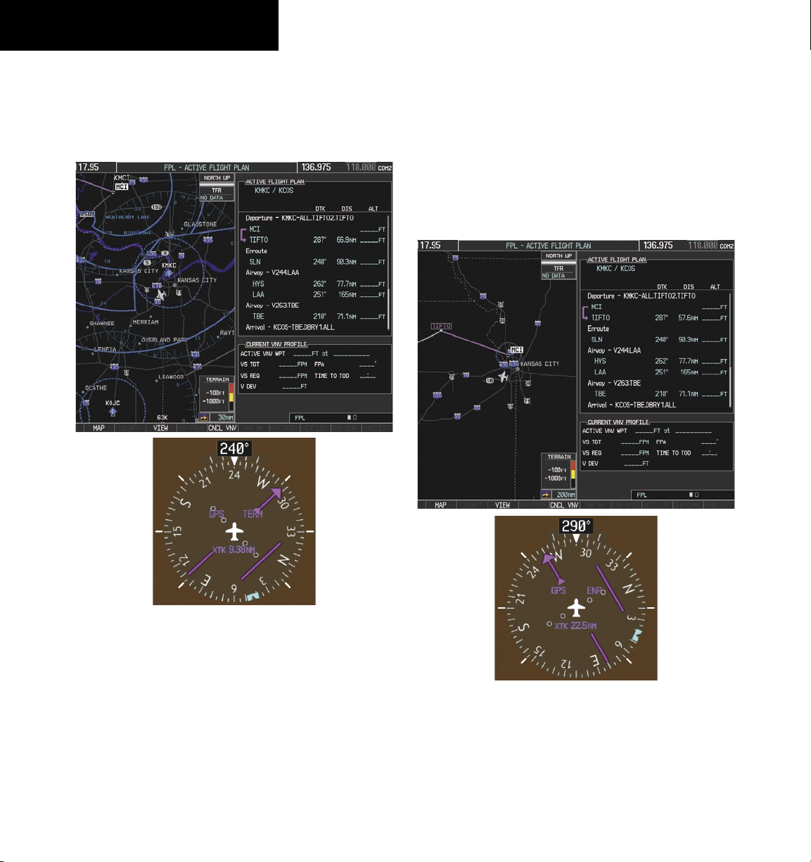
SECTION 7 – NAVIGATION
2)
Figure 7-11 shows the aircraft on the assigned
heading of 240º. ‘TERM’ (Terminal) is the current
CDI flight phase displayed on the HSI indicating
1.0 nm CDI scaling.
3)
ATC now assigns routing to join V4. A heading
of 290º is assigned to intercept V4. The aircraft
turns to heading 290° as seen in Figure 7-12.
Note the current CDI flight phase is now ENR
(Enroute). When the aircraft reached 30 nautical
miles from the departure point, the flight phase
changed from TERM to ENR on the HSI and CDI
scaling changed to 2.0 nm.
7-6
Figure 7-11 Assigned Heading of 240º
Figure 7-12 Assigned Heading of 290º
Garmin G1000 Cockpit Reference Guide for the Piper PA32
Page 61

4)
V4 will now be entered into the flight plan.
a)
Press the FMS Knob to activate the cursor.
b)
Turn the large FMS Knob to highlight the point
that proceeds V4 will be entered as shown in
Figure 7-13.
SECTION 7 – NAVIGATION
c)
Turn the small FMS Knob to display the Waypoint
Information Window. Enter the desired entry
point for V4, in this case Topeka VOR (TOP) will
be used as shown in Figure 7-14.
Figure 7-13 Begin Adding V4 to the Flight Plan
Garmin G1000 Cockpit Reference Guide for the Piper PA32
Figure 7-14 Entering V4 Entry Point
d)
Press the ENT Key. TOP is now inserted into the
flight plan as in Figure 7-15.
Figure 7-15 TOP Inserted into the Flight Plan
7-7
Page 62
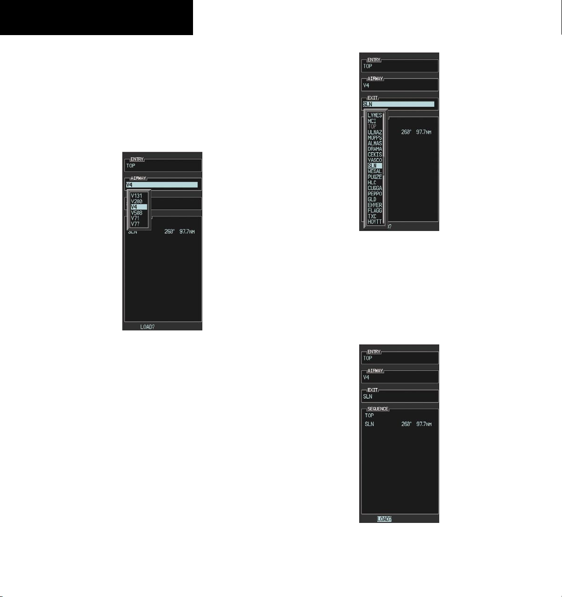
SECTION 7 – NAVIGATION
e)
With SLN still highlighted as in Figure 7-15, turn
the small FMS Knob to the right. The Waypoint
Information Page is displayed and the LD AIRWY
Softkey is now available.
f)
Press the LD AIRWY Softkey to display the list
of available airways for TOP as seen in Figure
7-16.
Figure 7-17 List of Available Exits for V4
i)
If necessary, turn either FMS Knob to select the
desired exit. In this case Salina VOR (SLN) is
selected as seen in Figure 7-17.
7-8
Figure 7-16 List of Available Airways for TOP
g)
Turn either FMS Knob to highlight V4 in the list
as seen in Figure 7-16.
h)
Press the ENT Key. The list of available exits for
V4 is now displayed as in Figure 7-17.
Garmin G1000 Cockpit Reference Guide for the Piper PA32
j)
Press the ENT Key. The selected airway and exit
are displayed the prompt “LOAD?” highlighted
as in Figure 7-18.
Figure 7-18 Ready to Load V4
k)
Press the ENT Key.
Page 63

l)
V4 is now loaded into the flight plan as shown
in Figure 7-19.
Figure 7-19 V4 is Loaded in the Flight Plan
SECTION 7 – NAVIGATION
d)
Verify the displayed leg is the desired leg and
press the ENT Key. Note in Figure 7-21, the
magenta arrow in the flight plan window and
magenta line on the map indicating V4 is now the
active flight plan leg. Note also, the crosstrack
(XTK) distance on the HSI indicating 16.9 nm to
the intercept point.
5)
V4 will now be made the active leg of the flight
plan.
a)
Press the FMS Knob to activate the cursor.
b)
Turn the large FMS Knob to highlight SLN. The
TO waypoint of the leg is selected in order to
activate the leg.
c)
Press the ACT LEG Softkey. The confirmation
window is now displayed as in Figure 7-20. Note
the TOP to SLN leg is actually part of V4.
Figure 7-20 Comfirm Active Leg
Garmin G1000 Cockpit Reference Guide for the Piper PA32
Figure 7-21 V4 Now Active Leg
7-9
Page 64

SECTION 7 – NAVIGATION
6)
The aircraft continues on heading 290º. When
2.0 nm from the intercept, the XTK will disappear
from the HSI and the CDI will be positioned on
the last dot indicating a 2.0 nm distance from
the centerline of the next course.
7)
As the CDI approaches center, the aircraft turns
onto the active leg as seen in Figure 7-22.
8)
At SLN, Victor Airway 244 (V244) will be
intercepted. Turn prompts will be displayed in
the PFD Navigation Status Box as seen in Figure
7-23.
Figure 7-23 Turn to Intercept V244
9)
As seen in Figure 7-24, V244 is now the active
flight plan leg.
7-10
Figure 7-24 V244 Now Active Leg
Figure 7-22 Turn on to Active Leg
Garmin G1000 Cockpit Reference Guide for the Piper PA32
Page 65

10)
At Lamar VOR (LAA) V263 will be intercepted.
See Figure 7-25.
Figure 7-25 HYS to LAA Leg Active
11)
ATC grants clearance to proceed direct to OPSHN
intersection to begin the arrival procedure. ATC
advises to expect an altitude of 10,000 feet at
OPSHN.
SECTION 7 – NAVIGATION
Figure 7-26 Direct To OPSHN
d)
Turn the large FMS Knob to place the cursor in
the VNV altitude field as shown in Figure 7-27.
a)
Press the FMS Knob to activate the cursor.
b)
Turn the large FMS Knob to select OPSHN in the
flight plan list.
c)
Press the
Direct-to ( )
Key. The Direct-to
Window is now displayed as shown in Figure
7-26.
Garmin G1000 Cockpit Reference Guide for the Piper PA32
Figure 7-27 Enter VNV Altitude
e)
An altitude of 10,000 feet is entered as requested
by ATC.
7-11
Page 66

SECTION 7 – NAVIGATION
f)
Press the ENT Key. The cursor is now displayed
in the VNV offset field as shown in Figure 7-28.
Figure 7-28 Enter VNV Offset Distance
g)
Enter the offset, or distance from the waypoint
at which the selected altitude will be reached. In
this case, three miles prior to OPSHN is entered.
In other words, the G1000 will give vertical
guidance so the aircraft will arrive at an altitude
of 10,000 feet three miles prior to OPSHN.
h)
Press the ENT Key twice to activate the directto. Note, in Figure 7-29, the magenta arrow
indicating the direct-to OPSHN after the offset
waypoint for OPSHN. The preceding offset
waypoint indicates the offset distance and
altitude that was previously entered. The
remaining waypoints in the loaded arrival
procedure have no database specified altitudes,
therefore, dashes are displayed. Keep the CDI
centered and maintain a track along the magenta
line to OPSHN.
NOTE: If the loaded arrival procedure has
waypoints with altitude constraints retrieved
from the database that will be used as is, the
altitude must be manually accepted by placing
the cursor over the desired altitude, then pressing
the ENT Key. The altitude will now be displayed
as light blue meaning it will now be used by the
system to determine vertical speed and deviation
guidance.
Figure 7-29 Direct-to Active
12)
While proceeding to OPSHN, the LPV approach
to runway 35R is preferred and will be used.
a)
Press the
PROC
Key to display the Procedures
Window.
7-12
Garmin G1000 Cockpit Reference Guide for the Piper PA32
Page 67

b)
‘SELECT APPROACH’ should be highlighted as
shown in Figure 7-30.
Figure 7-30 Proceudures Window
c)
Press the ENT Key. A list of available approaches
for the destination airport will be displayed as in
Figure 7-31.
SECTION 7 – NAVIGATION
d)
Turn either
FMS
Knob to select the LPV approach
for 35R as shown in Figure 7-31.
e)
Press the ENT Key. A list of available transitions
for the selected approach is displayed as shown
on Figure 7-32.
Figure 7-32 List of Available Transitions
Figure 7-31 List of Available Approaches
Garmin G1000 Cockpit Reference Guide for the Piper PA32
e)
Turn either FMS Knob to select the desired
transition. In this case, the Initial Approach Fix
(IAF) at HABUK will be used.
f)
Press the ENT Key.
7-13
Page 68

SECTION 7 – NAVIGATION
g)
With ‘LOAD?’ highlighted, again press the ENT
Key. The selected approach is added to the flight
plan as seen in Figure 7-33.
b)
Turn the large FMS Knob to place the cursor
in the altitude field associated with the IAF at
HABUK as in Figure 7-34.
Figure 7-33 Loaded Approach
13)
Note the altitude constraints associated with each
of the approach waypoints as seen in Figure 7-33.
These altitudes are loaded from the database and
are initially displayed as white text, indicating
these values will not be used in computing
vertical deviation guidance. The altitude values
must be designated for use by the pilot if they
are to be used in computing vertical guidance.
a)
Press the FMS Knob to activate the cursor.
Figure 7-34 Designate HABUK Altitude Constraint
c)
Press the ENT Key. Note the altitude is now
displayed as light blue text (Figure 7-35),
indicating that the value will now be used in
computing vertical guidance. The G1000 will be
using baro corrected altitude when giving vertical
guidance to these waypoints.
7-14
Garmin G1000 Cockpit Reference Guide for the Piper PA32
Page 69

d)
Turn the large FMS Knob to select the altitude
constraint associated with FALUR as seen in
Figure 7-35.
Figure 7-35 Designate FALUR Altitude Constraint
SECTION 7 – NAVIGATION
Altitude constraint values associated with the
Final Approach Fix (FAF) and waypoints beyond
the FAF cannot be designated for vertical
guidance. These altitude values will always
be displayed as white text, as in Figure 7-36.
Vertical guidance to the FAF and on to the Missed
Approach Point (MAP) is given using the WAAS
GPS altitude source, therefore, the displayed
altitude values are for reference only.
e)
Press the ENT Key to designate this altitude
constraint value for use in computing vertical
guidance. This altitude value will now be
displayed as light blue text. Note that altitude
values are now filled in for waypoints back to
where the previous altitude value was entered
for OPSHN.
Garmin G1000 Cockpit Reference Guide for the Piper PA32
Figure 7-36 Vertical Guidance is Active to the FAF
14)
As the aircraft approaches OPSHN, it may
be desirable to adjust how fast, or steep, the
upcoming descent will be. The default Flight Path
Angle (FPA) is -3.0 degrees and a required vertical
speed will be computed to maintain the -3.0 FPA.
To change the vertical flight path, perform the
following steps.
7-15
Page 70

SECTION 7 – NAVIGATION
a)
Press the VNV PROF Softkey to place the cursor
in the target vertical speed field (VS TGT) as
shown in Figure 7-37.
b)
At this point, the descent vertical speed can be
selected, or the FPA can be selected. Turn the
large FMS Knob to select the desired selection
field, then turn the small
desired value.
Note the information now displayed in the
‘CURRENT VNV PROFILE’ box. Also, note the
offset waypoint and gray circle are now displayed
on the map. The gray circle marks the Top of
Descent (TOD). In this example, vertical guidance
will be provided at the TOD that will result in a
-3.0 degree FPA descent to an altitude of 10,000
feet upon reaching the offset waypoint.
FMS Knob to enter the
15)
As seen in Figure 7-38, the aircraft is approaching
TOD. Note the target vertical speed required
to reached the selected altitude. The Vertical
Deviation Indicator (VDI) and the Required
Vertical Speed Indicator (RVSI) are now displayed
on the PFD as shown in Figure 7-39.
7-16
Figure 7-37 Adjusting the Descent
c)
Press the ENT Key.
Figure 7-38 Approaching Top of Descent (TOD)
Vertical
Deviation
Indicator
(VDI)
Figure 7-39 VDI & RVSI Upon Reaching Top of Descent (TOD)
Garmin G1000 Cockpit Reference Guide for the Piper PA32
Target
Altitude
Required
Vertical
Speed
Indicator
(RVSI)
Page 71

16)
Upon reaching TOD, a descent vertical speed is
established which places the VSI pointer in line
with the RVSI as shown in Figure 7-40.
SECTION 7 – NAVIGATION
18)
The aircraft is approaching OPSHN. The upcoming
turn and next heading will be annunciated at
the top left of the PFD as seen in Figure 7-42.
Initiate the turn and maneuver the aircraft on
a track through the turn radius to intercept the
magenta line for the OPSHN to FSHER leg and
center the CDI.
Keep Vertical
Deviation Pointer
Centered
Figure 7-40 VDI & RVSI Showing Correctly Established Descent
17)
When the aircraft is one minute from the bottom
Align Actual
Vertical Speed
with Required
Vertical Speed
of descent (BOD) this will be annunciated as
shown in Figure 7-41. Upon reaching the offset
waypoint for OPSHN, the aircraft will be at
10,000 feet.
Figure 7-42 Turn to intercept OPSHN to FSHER Leg
Figure 7-41 Approaching Bottom of Descent (BOD) at OPSHN
Offset Waypoint
Garmin G1000 Cockpit Reference Guide for the Piper PA32
7-17
Page 72

SECTION 7 – NAVIGATION
19)
After passing OPSHN, the next leg of the arrival
will turn magenta as shown in Figure 7-43.
The magenta arrow in the flight plan list now
indicates the OPSHN to FSHER leg of the arrival
procedure is now active.
7-18
Figure 7-43 Tracking the OPSHN to FSHER Leg
20)
The flight continues through the arrival procedure
to PYNON (see Figure 7-44). At a point 31
nautical miles from the destination airport, the
phase of flight scaling for the CDI will change to
Terminal Mode and is annunciated by displaying
‘TERM’ on the HSI.
There will be a descent to HABUK in the next leg.
Note the TOD point on the map. Annunciations
for the upcoming turn and descent, as well as the
VDI and RVSI, appear on the PFD as the flight
progresses.
Garmin G1000 Cockpit Reference Guide for the Piper PA32
Figure 7-44 Approaching PYNON
Page 73

21)
Upon passing PYNON the approach procedure
will automatically become active. The approach
may be activated at any point to proceed directly
to the IAF. In this example, the aircraft has
progressed through the final waypoint of the
arrival and the flight plan has automatically
sequenced to the IAF as the active leg, activating
the approach procedure (see Figure 7-45).
SECTION 7 – NAVIGATION
22)
The IAF is the next waypoint. At the TOD,
establish a descent vertical speed as previously
discussed in Step 16. The aircraft altitude will be
9,000 feet upon reaching HABUK.
Figure 7-45 Approach Leg is Now Active
To manually activate the approach procedure,
perform the following steps:
a)
Press the
b)
Turn the large
PROC
Key.
FMS
Knob to highlight ‘ACTIVATE
APPROACH’ as shown in Figure 7-46.
Figure 7-46 Activate Missed Approach
c)
Press the
ENT
Key to activate the approach.
Garmin G1000 Cockpit Reference Guide for the Piper PA32
Figure 7-47 Descending Turn to the Initial Approach Fix (IAF)
7-19
Page 74

SECTION 7 – NAVIGATION
23)
After crossing FALUR the next waypoint is the
FAF. The flight phase changes to LPV on the
HSI indicating the current phase of flight is in
Approach Mode and the approach type is LPV.
CDI scaling changes accordingly and is used much
like a localizer when flying an ILS approach. The
RVSI is no longer displayed and the VDI changes to
the Glidepath Indicator (as shown in Figure 7-48)
when the final approach course becomes active.
The descent continues through the FAF (CEGIX)
using the Glidepath Indicator, as one would use
a glideslope indicator, to obtain an altitude “AT”
7,800 feet at the FAF. Note the altitude restriction
lines over and under (At) the altitude in the ‘ALT’
field in Figure 7-48.
24)
After crossing CEGIX, the aircraft continues
following the glidepath to maintain the descent
to “AT or ABOVE” 6,370 feet at the Missed
Approach Point (MAP) (RW35R) as seen in Figure
7-49.
7-20
Figure 7-48 Descending to the FAF
Garmin G1000 Cockpit Reference Guide for the Piper PA32
Figure 7-49 Descending to the Missed Approach Point
Page 75

In this missed approach procedure, the fix
immediately following the MAP (in this case
‘6368FT’) is not part of the published procedure.
It is simply a fix that defines a leg which guides
the aircraft along the runway centerline until the
required altitude to make the first turn on the
missed approach is exceeded. In this case, if the
aircraft altitude is below the specified altitude
(6,368 feet) after crossing the MAP, a direct-to
will be established to this fix until an altitude of
6,368 feet reached. After reaching 6,368 feet,
a direct-to will be established to the published
fix (in this case MOGAL). If the aircraft altitude
is above the specified altitude after crossing
the MAP, a direct-to will be established to the
published fix (MOGAL) to begin the missed
approach procedure. The altitude constraint value
defaults to 400 feet AGL when the fix is not part
of the published procedure.
SECTION 7 – NAVIGATION
A direct-to is initiated to MOGAL, which is the
Missed Approach Hold Point (MAHP) as seen in
Figure 7-50. The aircraft is climbing to 10,000
feet. The CDI flight phase now changes from LPV
to MAPR as seen on the HSI.
In some missed approach procedures this altitude
fix may be part of the published procedure. For
example, the procedure dictates a climb to 5,500
feet, then turn left and proceed to the Missed
Approach Hold Point (MAHP). In this case, the
altitude fix would be labeled ‘5500FT’. Again, if
the aircraft altitude is lower than this prescribed
altitude, a direct-to will be established to this
fix when the missed approach procedure is
activated.
25)
Upon reaching the MAP, it is decided to execute
a missed approach. Automatic waypoint
sequencing is suspended past the MAP. Press
the
SUSP
Softkey on the PFD to resume automatic
waypoint sequencing through the missed
approach procedure.
Garmin G1000 Cockpit Reference Guide for the Piper PA32
Figure 7-50 Missed Approach Active
7-21
Page 76

SECTION 7 – NAVIGATION
26)
The aircraft continues climbing to “AT or ABOVE”
10,000 feet at MOGAL. A holding pattern will
be established at the MAHP (MOGAL) as shown
in Figure 7-51.
7.4 AIRPORT INFORMATION
Figure 7-53 Airport Information Page
7-22
Figure 7-51 Establishing the Holding Pattern
27)
The aircraft maintains 10,000 feet while following
the magenta line through the hold as in Figure
7-52.
Figure 7-52 Hold Established
Garmin G1000 Cockpit Reference Guide for the Piper PA32
Select the Airport Information Page
1)
Turn the large
group.
2)
Turn the small
rectangular page icon. Initially, information
for the airport closest to the aircraft’s present
position is displayed.
Select an Airport from the Database
1)
With the Airport Information Page displayed,
press the
2)
Enter the desired airport identifier.
FMS
Knob to select the ‘WPT’ page
FMS
Knob to select the first
FMS
Knob to activate the cursor.
Page 77

SECTION 7 – NAVIGATION
Select an Airport from the Active Flight Plan
1)
With the Airport Information Page displayed,
press the
2)
Turn the small
FMS
Knob to activate the cursor.
FMS
Knob to the left to display
a list of flight plan airports as shown in Figure
7-54.
Figure 7-54 Flight Plan Airport List
3)
Turn the large
FMS
Knob to select the desired
airport.
4)
Press the
ENT
Key.
Select a Nearest Airport
1)
With the Airport Information Page displayed,
press the
2)
Turn the small
FMS
Knob to activate the cursor.
FMS
Knob to the left. Initially, a
flight plan airport list is displayed as in Figure 7-
54. The list is populated only when navigating
a flight plan.
4)
Turn the large
FMS
Knob to select the desired
airport.
5)
Press the
ENT
Key.
Select a Recently Entered Airport Identifier
1)
With the Airport Information Page displayed,
press the
2)
Turn the small
FMS
Knob to activate the cursor.
FMS
Knob to the left. Initially, a
flight plan waypoint list is displayed as in Figure
7-54. The list is populated only when navigating
a flight plan.
3)
Turn the small
FMS
Knob to the right to display
the ‘RECENT’ airports as shown in Figure 7-56.
Figure 7-56 Recently Entered Airports List
4)
Turn the large
FMS
Knob to select the desired
airport.
5)
Press the
ENT
Key.
Select an Airport by Facility Name or City Location
Figure 7-55 Nearest Airport List
3)
Turn the small
FMS
Knob to the right to display
the ‘NRST’ airports to the aircraft’s current
position as shown in Figure 7-55.
Garmin G1000 Cockpit Reference Guide for the Piper PA32
1)
With the Airport Information Page displayed,
press the
2)
Turn the large
FMS
Knob to activate the cursor.
FMS
Knob to select the facility
name or location (city) field.
3)
Enter the desired facility name or city.
5)
Press the ENT Key. If there are duplicate names
in the database, a list is displayed from which to
choose the desired location.
6)
To remove the flashing cursor, press the
Knob.
FMS
7-23
Page 78

SECTION 7 – NAVIGATION
Access Runway Information
1)
With the Airport Information Page displayed,
press the
2)
Turn the large
FMS
Knob to activate the cursor.
FMS
Knob to place the cursor on
the ‘RUNWAYS’ identifier field.
3)
Turn the small
FMS
Knob in the direction of the
green arrow to display the next runway for the
selected airport. Continue turning the small
Knob to select the desired runway.
4)
To remove the flashing cursor, press the
Knob.
Access Frequency Information
1)
With the Airport Information Page displayed,
press the
2)
Turn the large
FMS
Knob to activate the cursor.
FMS
Knob to move the cursor to
the Frequencies box.
3)
Turn either
FMS
Knob to scroll through the list,
placing the cursor on the desired frequency.
If a listed frequency has sector or altitude
restrictions, the frequency is preceded by an info
ENT
(‘i’) designation. Press the
Key to view the
information. The following may be displayed with
the frequency:
• ‘TX’ – transmit only
• ‘RX’ – receive only
• ‘PT’ – part time frequency
4)
Press the
ENT
Key to place the selected frequency
in the standby field of the COM or NAV box.
5)
To remove the cursor, press the
FMS
Knob.
FMS
FMS
7.5 INTERSECTION INFORMATION
Select the Intersection Information Page
1)
Turn the large
group.
2)
Turn the small
rectangular page icon.
Figure 7-57 Intersection Information Page
Access Information on an Intersection
1)
With the Intersection Information Page displayed,
press the
2)
Enter an intersection identifier and press the
Key.
3)
Press the
cursor.
FMS
Knob to select the ‘WPT’ page
FMS
Knob to select the second
FMS
Knob to activate the cursor.
FMS
Knob to remove the flashing
ENT
7-24
Garmin G1000 Cockpit Reference Guide for the Piper PA32
Page 79

SECTION 7 – NAVIGATION
7.6 NDB INFORMATION
Figure 7-58 NDB Information Page
Select the NDB Information Page
1)
Turn the large
group.
2)
Turn the small
rectangular page icon
View Information on a Specific NDB
1)
With the NDB Information Page displayed, press
the
FMS
2)
Turn the large
selection field (identifier, name or closest city).
3)
Enter an identifier, name or city and press the
ENT
Key.
4)
Press the
cursor.
FMS
Knob to select the ‘WPT’ page
FMS
Knob to select the third
Knob to activate the cursor.
FMS
Knob to highlight the desired
FMS
Knob to remove the flashing
7.7 VOR INFORMATION
Figure 7-59 VOR Information Page
Select the VOR Information Page
1)
Turn the large
group.
2)
Turn the small
rectangular page icon.
Access Information on a VOR
1)
With the VOR Information Page displayed, press
the
FMS
2)
Turn the large
selection field (identifier, name or closest city).
3)
Enter an identifier, name or city and press the
ENT
Key.
4)
The ‘FREQUENCY’ field is now highlighted. If
desired, press the
in the NAV receiver standby field.
FMS
Knob to select the ‘WPT’ page
FMS
Knob to select the fourth
Knob to activate the cursor.
FMS
Knob to highlight the desired
ENT
Key to place the frequency
5)
Press the
cursor.
Garmin G1000 Cockpit Reference Guide for the Piper PA32
FMS
Knob to remove the flashing
7-25
Page 80

SECTION 7 – NAVIGATION
7.8 USER WAYPOINT INFORMATION PAGE
See the Flight Planning section for a discussion on
creating and modifying user defined waypoints.
2)
Press the
to highlight the desired airport.
3)
Press the
cursor.
Access Runway Information for the Selected Airport
FMS
Knob, then turn the large
FMS
Knob to remove the flashing
FMS
Knob
7.9 NEAREST AIRPORTS
Figure 7-60 Nearest Airports Page
Nearest Airport Information on the MFD
Select the Nearest Airports Page
1)
Turn the large
group.
2)
Turn the small
rectangular page icon.
FMS
Knob to select the ‘NRST’ page
FMS
Knob to select the first
1)
With the Nearest Airports Page displayed, press
the
RNWY
Softkey to place the cursor in the
‘RUNWAYS’ field.
2)
Turn the small
runway.
3)
Press the
cursor.
Quickly Tune the COM Transceiver to a Nearby
Airport Frequency
1)
With the Nearest Airports Page displayed, press
the
FREQ
‘FREQUENCIES’ field.
2)
Turn either
frequency.
3)
Press the
placed in the COM standby frequency field.
4)
Press the
frequency in the active field.
5)
Press the
cursor.
FMS
Knob to select the desired
FMS
Knob to remove the flashing
Softkey to place the cursor in the
FMS
Knob to select the desired
ENT
Key. The selected frequency is
Frequency Transfer
FMS
Knob to remove the flashing
Key to place the
7-26
Initially, the closest airport to the aircraft’s present
position is displayed.
Access Information on a Specific Airport
1)
With the Nearest Airports Page displayed,
press the
‘NEAREST AIRPORTS’ field. The first airport in
the nearest airports list is highlighted.
APT
Softkey to place the cursor in the
Garmin G1000 Cockpit Reference Guide for the Piper PA32
Page 81

SECTION 7 – NAVIGATION
Nearest Airports Information on the PFD
Bearing TO
Airport Symbol
Identifier
Primary COM Frequency
Figure 7-61 Nearest Airports Window
Press the
NRST
Softkey to display the PFD Nearest
Airports Window.
View Information on a Specific Airport in the List
1)
With the Nearest Airports Window displayed,
turn either
FMS
Knob to place the cursor on the
desired airport identifier.
2)
Press the
ENT
information.
3)
Press the
ENT
Key again (cursor is on ‘BACK’) to
return to the list.
Distance
Runway Length
Key t o di s p l a y ai r p o r t
7.10 NEAREST INTERSECTIONS
Figure 7-62 Nearest Intersections Page
Select the Nearest Intersections Page
1)
Turn the large
group.
2)
Turn the small
rectangular page icon.
FMS
Knob to select the ‘NRST’ page
FMS
Knob to select the second
Load an Airport COM Frequency into the Active COM
1)
With the Nearest Airports Window displayed,
turn either
FMS
Knob to place the cursor on
the desired airport frequency shown in the
window.
2)
Press the
ENT
Key and the selected frequency will
be placed in the COM standby frequency field.
3)
Press the
Frequency Transfer
Key to make the
frequency the active frequency.
Garmin G1000 Cockpit Reference Guide for the Piper PA32
View Information on the Nearest Intersection
1)
With the Nearest Intersections Page displayed,
press the
2)
Turn either
FMS
Knob to activate the cursor.
FMS
Knob to select the desired
intersection.
3)
Press the
FMS
Knob to remove the flashing
cursor.
7-27
Page 82

SECTION 7 – NAVIGATION
7.11 NEAREST NDB
Figure 7-63 Nearest NDB Page
Select the Nearest NDB Page
1)
Turn the large
group.
2)
Turn the small
rectangular page icon.
Access Information on a Specific NDB
1)
With the Nearest NDB Page displayed, press the
FMS
Knob to activate the cursor.
FMS
Knob to select the ‘NRST’ page
FMS
Knob to select the third
7.12 NEAREST VOR
Figure 7-64 Nearest VOR Page
Select the Nearest VOR Page
1)
Turn the large
group.
2)
Turn the small
rectangular page icon.
View Information on the Nearest VOR
1)
With the Nearest VOR Page displayed, press the
VOR
Softkey to place the cursor in the ‘NEAREST
VOR’ box.
FMS
Knob to select the ‘NRST’ page
FMS
Knob to select the fourth
7-28
2)
Turn either
The remaining information on the Nearest NDB
Page pertains to the selected NDB.
3)
Press the
cursor.
FMS
Knob to select the desired NDB.
FMS
Knob to remove the flashing
Garmin G1000 Cockpit Reference Guide for the Piper PA32
2)
Turn either
3)
Press the
cursor.
Select and Load a VOR Frequency
1)
With the Nearest VOR Page displayed, press the
FREQ
the ‘FREQUENCY’ field.
2)
Press the
is placed in the NAV standby frequency field.
FMS
Knob to select a VOR.
FMS
Knob to remove the flashing
Softkey to highlight the VOR frequency in
ENT
Key. The selected VOR frequency
Page 83

3)
Press the
cursor.
FMS
Knob to remove the flashing
3)
Press the
cursor.
SECTION 7 – NAVIGATION
FMS
Knob to remove the flashing
7.13 NEAREST USER WAYPOINT
Figure 7-65 Nearest User Waypoints Page
Select the Nearest User Waypoint Page
1)
Turn the large
group.
2)
Turn the small
rectangular page icon.
Select a Nearest User Waypoint
1)
With the Nearest User Waypoint Page displayed,
press the
previously entered User Waypoints are within 200
nm, these will be displayed with the closest listed
first.
2)
Turn either
waypoint. The remaining information on the
Nearest User Waypoint Page pertains to the
selected Nearest User Waypoint.
FMS
Knob to select the ‘NRST’ page
FMS
Knob to select the fifth
FMS
Knob to activate the cursor. If any
FMS
Knob to select the desired
7.14 NEAREST FREQUENCIES
Figure 7-66 Nearest Frequencies Page
Select the Nearest Frequencies Page
1)
Turn the large
group.
2)
Turn the small
rectangular page icon.
Select and Load the Nearest ARTCC, FSS, or Weather
Frequency
1)
With the Nearest Frequencies Page displayed,
press the
cursor in the appropriate field.
2)
Turn the
or frequency.
3)
Press the
COM frequency standby field.
4)
Press the
cursor.
FMS
Knob to select the ‘NRST’ page
FMS
Knob to select the sixth
ARTCC, FSS, or Wx
FMS
Knobs to select the desired facility
ENT
Key to load the frequency into the
FMS
Knob to remove the flashing
Softkey to place the
Garmin G1000 Cockpit Reference Guide for the Piper PA32
7-29
Page 84

SECTION 7 – NAVIGATION
7.15 NEAREST AIRSPACES
Figure 7-67 Nearest Airspaces Page
Select the Nearest Airspaces Page
1)
Turn the large
group.
2)
Turn the small
rectangular page icon.
FMS
Knob to select the ‘NRST’ page
FMS
Knob to select the seventh
View Additional Details for a Listed Airspace
1)
With the Nearest Airspace Page displayed, press
the
FMS
Knob to activate the cursor.
2)
Turn the large
FMS
Knob to scroll through the
list, highlighting the desired airspace.
3)
Press the
ALERTS
Softkey to place the cursor in
the ‘AIRSPACE ALERTS’ field.
4)
Turn either
FMS
Knob to select the desired
airspace.
5)
Press the
FMS
Knob to remove the flashing
cursor.
View and Quickly Load the Frequency for a
Controlling Agency
1)
With the Nearest Airspace Page displayed,
press the
FREQ
Softkey to place the cursor in
‘FREQUENCIES’ field.
2)
Turn either
FMS
Knob to select the desired
frequency.
3)
Press the
ENT
Key to load the frequency into the
COM frequency standby field.
7-30
Airspace Alerts Box
• If the projected course takes the aircraft inside an
airspace within the next ten minutes, ‘Ahead’ is
displayed.
• If the aircraft is within two nautical miles of an
airspace and the current course takes the aircraft
inside, ‘Ahead < 2 nm’ is displayed.
• If the aircraft is within two nautical miles of an
airspace and the current course will not take the
aircraft inside, ‘Within 2 nm’ is displayed.
• If the aircraft has entered an airspace, ‘Inside’ is
displayed.
Garmin G1000 Cockpit Reference Guide for the Piper PA32
4)
Press the
cursor.
FMS
Knob to remove the flashing
Page 85

SECTION 8: FLIGHT PLANNING
The following discussions pertain to the Multi Function
Display, unless otherwise indicated.
8.1 USER DEFINED WAYPOINTS
SECTION 8 – FLIGHT PLANNING
4)
Repeat steps 2 and 3 until the desired name is
entered.
5)
Press the
6)
Press the
waypoint identifier.
7)
The cursor is now in the ‘REFERENCE WAYPOINTS’
field. If desired, the waypoint can be defined by
a reference waypoint. Turn the
enter the position coordinates or the radial and
distance from the reference waypoint.
8)
Press the
cursor.
Modify a User Waypoint
1)
With the User Waypoint Information Page
displayed, press the
cursor.
ENT
Key.
ENT
Key a again to accept the new
FMS
Knobs to
FMS
Knob to remove the flashing
FMS
Knob to activate the
Figure 8-1 User WPT Information Page
Select the User WPT Information Page
1)
Turn the large
group.
2)
Turn the small
rectangular page icon.
Create a New User Waypoint
1)
With the User Waypoint Information Page
displayed, press the
created at the current aircraft position.
2)
Turn the small
of the waypoint name.
3)
Turn the large
the next character field.
FMS
Knob to select the ‘WPT’ page
FMS
Knob to select the fifth
NEW
Softkey. A waypoint is
FMS
Knob to enter first character
FMS
Knob to move the cursor to
Garmin G1000 Cockpit Reference Guide for the Piper PA32
2)
Turn the large
the desired field and turn the small
make changes.
3)
Press the
4)
Press the
cursor.
Delete a User Waypoint
1)
Select the User Waypoint Information Page
and press
Information Page Options or press the
Softkey.
2)
Turn the large
Waypoint’ and press the
‘Would you like to delete the user waypoint’ is
displayed. With ‘YES’ highlighted, press the
Key.
FMS
Knob to move the cursor to
ENT
Key to accept the changes.
FMS
Knob to remove the flashing
MENU
to display the User Waypoint
FMS
Knob to select ‘Delete User
ENT
Key. The message
FMS
Knob to
DELETE
ENT
8-1
Page 86

SECTION 8 – FLIGHT PLANNING
Create User Waypoints from the Navigation Map Page
1)
With the Navigation Map Page displayed, push
the
Joystick
target pointer is displayed at the present aircraft
position.
2)
Move the
desired position
3)
Press the
Page is now displayed with the captured
position.
4)
Turn the
5)
Press the
The first reference waypoint field is highlighted.
6)
If desired, turn the
identifier of the reference waypoint and the radial
and distance to the reference waypoint. Press
the
ENT
to activate the panning function. The
Joystick
ENT
FMS
ENT
Key to accept.
to place the pointer at the
Key. The User Waypoint Information
Knobs to select a waypoint name.
Key to accept the selected name.
FMS
Knobs to enter the
Figure 8-3 Active Flight Plan Page on the MFD
8.3 ACTIVATE A STORED FLIGHT PLAN
1)
Press the
to display the Flight Plan Catalog Page.
FPL
Key and turn the small
FMS
Knob
8-2
7)
Press the
cursor.
FMS
Knob to remove the flashing
8.2 VIEWING THE ACTIVE FLIGHT PLAN
Press the
Figure 8-2 Active Flight Plan Window on the PFD
FPL
Key.
Garmin G1000 Cockpit Reference Guide for the Piper PA32
Figure 8-4 Flight Plan Catalog Page
2)
Press the
3)
Turn the large
flight plan and press the
4)
With ‘OK’ highlighted, press the
activate the flight plan. To cancel the flight plan
FMS Knob
FMS
Knob to highlight the desired
to activate the cursor.
ACTIVE
Softkey.
ENT
Key to
Page 87

SECTION 8 – FLIGHT PLANNING
activation, turn the large
‘CANCEL’ and press the
FMS
Knob to highlight
ENT
Key.
8.4 ACTIVATE A FLIGHT PLAN LEG
1)
From the Active Flight Plan Page, press the
Knob to activate the cursor and turn the large
FMS
Knob to highlight the desired destination
waypoint.
2)
Press the
OR
3)
Press the
option from the page menu and press the
Key. This step must be used when activating a
leg from the PFD.
4)
With ‘Activate’ highlighted, press the
Figure 8-5 Activate Flight Plan Leg Confirmation
ACT LEG
MENU
Softkey (using MFD only).
Key, select the ‘Activate Leg’
ENT
FMS
ENT
Key.
3)
Turn the large
Flight Plan’ and press the
highlighted, press the
FMS
Knob to highlight ‘Delete
ENT
ENT
Key to deactivate the
flight plan. This will not delete the stored flight
plan, only the active flight plan.
Figure 8-7 Delete Flight Plan Confirmation
8.6 INVERT ACTIVE FLIGHT PLAN
1)
From the Active Flight Plan Page, press the
Key to display the Page Menu.
2)
Turn the large
Flight Plan’ and press the
flight plan remains intact in its flight plan catalog
storage location.
3)
With ‘OK’ highlighted, press the
the flight plan.
FMS
Knob to highlight ‘Invert
ENT
Key. The original
Key. With ‘OK’
MENU
ENT
Key to invert
8.5 STOP NAVIGATING A FLIGHT PLAN
1)
2)
Press the
Page.
Press the
window.
FPL
Key to display the Active Flight Plan
MENU
Key to display the Page Menu
Figure 8-6 Delete Flight Plan
Garmin G1000 Cockpit Reference Guide for the Piper PA32
Figure 8-8 Invert Flight Plan
Figure 8-9 Invert Flight Plan Confirmation
8-3
Page 88

SECTION 8 – FLIGHT PLANNING
8.7 CREATE A NEW FLIGHT PLAN
Create a New Flight Plan Using the MFD
8)
When all waypoints have been entered, press the
FMS
Knob to return to the Flight Plan Catalog
Page. The new flight plan is now in the list.
1)
Press the
FPL
Key and turn the small
FMS
to display the Flight Plan Catalog Page.
2)
Press the
NEW
Softkey to display a blank flight
plan page for the first empty storage location.
Figure 8-10 Create FPL on MFD
3)
Turn the small
FMS
Knob to display the Waypoint
Information Window.
4)
Turn the small
FMS
Knob to the right enter the
first character of the identifier of the departure
waypoint. Turning the knob to the left will access
the FPL, NRST, and RECENT waypoint list.
5)
Turn the large
FMS
Knob to move the cursor to
the next character field. Repeat steps 4 and 5
until the desired identifier has been entered.
Knob
Create a New Flight Plan Using the PFD
NOTE: A flight plan cannot be entered using the
PFD if another flight plan is active.
NOTE: After the first leg is entered (using the
PFD only), it is immediately activated.
1)
Press the
activate the cursor.
2)
Turn the small
of the destination waypoint identifier. Turn the
large
to the next character position.
3)
Repeat step 2 to spell out the rest of the waypoint
identifier.
4)
Press the
for entering of the next flight plan waypoint.
5)
Repeat steps 2 through 4 to enter the identifier
for each additional flight plan waypoint.
FPL
Key, then press the
FMS
Knob to enter the first letter
FMS
Knob to the right to move the cursor
ENT
Key and the cursor is now ready
FMS
Knob to
8-4
Figure 8-11 Waypoint Info Window
6)
Press the
7)
Repeat step number 3, 4, and 5 to enter
ENT
Key.
the identifier for each additional flight plan
waypoint.
Garmin G1000 Cockpit Reference Guide for the Piper PA32
6)
Once all waypoints have been entered, press the
FMS
Knob remove the cursor. The new flight plan
is now active.
Figure 8-12 Creating Flight Plan on the PFD
Page 89

8.8 ENTER AN AIRWAY IN A FLIGHT PLAN
1)
Press the FPL Key to display the active flight plan
or display a stored flight plan.
2)
Press the FMS Knob to activate the cursor.
3)
Turn the large FMS Knob to highlight the
waypoint before which the airway will be
entered.
Figure 8-13 Airway Insertion Point
SECTION 8 – FLIGHT PLANNING
5)
When the desired entry point is entered, press
the
ENT
Key.
Figure 8-15 Airway Entry Point Loaded
6)
Turn the small FMS Knob to display the Waypoint
Information Window.
4)
Turn the small FMS Knob to display the Waypoint
Information Window and begin entering the
desired airways entry point.
Figure 8-14 Load Airway Entry Point
Garmin G1000 Cockpit Reference Guide for the Piper PA32
Figure 8-16 Display Waypoint Information Window
7)
Press the
LD AIRWY
Softkey. A list of available
airways is now displayed.
8-5
Page 90

SECTION 8 – FLIGHT PLANNING
Figure 8-19 Airway Added to Flight Plan
8.9 LOAD A DEPARTURE
Figure 8-17 Select Desired Airway
8)
Turn either FMS Knob to highlight the desired
airway.
9)
Press the ENT Key. A list of available exits is now
displayed.
10)
Turn either FMS Knob to highlight the desired
exit point.
Figure 8-18 Select Desired Exit Point
11)
With the desired exit point highlighted, press the
ENT
Key.
12)
With ‘LOAD?’ highlighted, press the
ENT
Key.
See the Procedures section for a discussion on loading
and activating departure procedures.
8.10 LOAD AN ARRIVAL
See the Procedures section for a discussion on loading
and activating arrival procedures.
8.11 LOAD AN APPROACH
See the Procedures section for a discussion on loading
and activating approach procedures.
8.12 REMOVE A DEPARTURE, ARRIVAL, APPROACH, OR AIRWAY FROM A FLIGHT PLAN
1)
With the Active or Stored Flight Plan Page
displayed, press the FMS Knob to activate the
cursor.
2)
Turn the large FMS Knob to highlight the title
for the approach, departure, arrival, or airway to
be deleted. Titles appear in white directly above
the procedure’s waypoints.
3)
Press the CLR Key to display a confirmation
window. With ‘OK’ highlighted, press the
ENT Key to remove the selected procedure or
airway.
8-6
Garmin G1000 Cockpit Reference Guide for the Piper PA32
Page 91

8.13 STORE A FLIGHT PLAN
1)
After creating a flight plan on either the PFD
or MFD, it may be saved by pressing the
Key.
2)
Turn the large
Plan’ and press the
3)
With ‘OK’ highlighted, press the
the flight plan.
Figure 8-20 Store Flight Plan Confirmation
FMS
Knob to highlight ‘Store Flight
ENT
Key.
ENT
MENU
Key to store
SECTION 8 – FLIGHT PLANNING
3)
Press the
Name)’ confirmation window.
Figure 8-21 Remove Waypoint Confirmation
4)
With ‘OK’ highlighted, press the
remove the waypoint. To cancel the delete
request, turn the large
‘CANCEL’ and press the
5)
Once all changes have been made, press the
Knob to remove the cursor.
CLR
Key to display a ‘REMOVE (Wpt
ENT
FMS
Knob to highlight
ENT
Key.
Key to
FMS
8.14 EDIT A STORED FLIGHT PLAN
1)
Press the
to display the Flight Plan Catalog Page.
2)
Press the
3)
Turn the large
flight plan and press the
4)
Turn the large
the desired locations for entering changes.
5)
Turn the
then press the
6)
Press the
Catalog Page.
FPL
Key and turn the small
FMS Knob
FMS
FMS Knob
to activate the cursor.
FMS
Knob to highlight the desired
ENT
Key.
FMS
Knob to place the cursor in
Knobs to make the desired changes,
ENT
Key.
to return to the Flight Plan
FMS
8.15 DELETE A WAYPOINT FROM THE FLIGHT PLAN
1)
With either the Active or Stored Flight Plan
displayed, press the
cursor.
FMS
Knob to activate the
Knob
8.16 INVERT AND ACTIVATE A STORED FLIGHT PLAN
1)
From the Flight Plan Catalog Page, press the
Knob to activate the cursor.
2)
Turn the large
flight plan.
3)
Press the
stored flight plan?’ will be displayed.
4)
With ‘OK’ highlighted, press the
selected flight plan is now inverted and activated.
The original flight plan remains intact in its flight
plan catalog storage location.
FMS
Knob to highlight the desired
INVERT
Softkey. ‘Invert and activate
ENT
Key. The
FMS
2)
Turn the large
to be deleted.
FMS
Knob to select the waypoint
Garmin G1000 Cockpit Reference Guide for the Piper PA32
8-7
Page 92

SECTION 8 – FLIGHT PLANNING
8.17 COPY A FLIGHT PLAN
1)
From the Flight Plan Catalog press the
to activate the cursor
2)
Turn the large
plan to be copied.
3)
Press the
4)
A ‘Copy to flight plan #?’ confirmation window is
displayed. With ‘OK’ highlighted, press the
Key to copy the flight plan. To cancel, turn the
large
FMS
the
ENT
FMS
Knob to highlight the flight
COPY
Softkey.
Knob to highlight ‘CANCEL’ and press
Key.
8.18 DELETE A FLIGHT PLAN
1)
From the Flight Plan Catalog Page, press the
Knob to activate the cursor.
2)
Turn the large
plan to be deleted.
3)
Press the
4)
A ‘Delete flight plan #?’ confirmation window is
displayed. With ‘OK’ highlighted, press the
Key to delete the flight plan. To cancel, turn the
large
FMS
the
ENT
FMS
Knob to highlight the flight
DELETE
Knob to highlight ‘CANCEL’ and press
Key.
Softkey.
FMS
Knob
ENT
FMS
ENT
4)
If the selected waypoint is to be placed elsewhere
in the flight plan, press the
the cursor. Waypoints are inserted
cursor.
5)
After placing the cursor at the desired point in
the list of waypoints, press the
6)
To change the user waypoint name, follow the
procedure for modifying a user waypoint.
8.20 TRIP PLANNING
1)
Turn the large
group.
2)
Turn the small
rectangular page icon.
3)
The current page mode is displayed at the top of
the page: ‘AUTOMATIC’ or ‘MANUAL’. To change
the page mode, press the
Softkey.
Starting WPT Ending WPT
FMS
FMS
Knob to activate
ABOVE
LD WPT
Knob to select the ‘AUX’ page
FMS
Knob to select the first
AUTO
or
Softkey.
MANUAL
the
8-8
8.19 GRAPHICAL FLIGHT PLAN CREATION
1)
Press the
Page.
2)
Press the
the
point on the map to be inserted as a waypoint
in the flight plan.
3)
Press the
will be inserted at the end of the flight plan.
The default user waypoint naming is USR000,
USR001, USR002 and so on.
FPL
Joystick
Joystick
LD WPT
Key to display the Active Flight Plan
to activate the map pointer. Use
to move the pointer to the desired
Softkey. The selected waypoint
Garmin G1000 Cockpit Reference Guide for the Piper PA32
Figure 8-22 Trip Planning Page
Page 93

4)
For Direct-to planning, press the
WPTS
and verify that the starting waypoint field
indicates ‘P.POS’ (present position). If necessary,
MENU
press the
Key and select ‘Set WPT to
Present Position’ to display ‘P.POS’. Press the
Key and the flashing cursor moves to the ending
waypoint field. Turn the
FMS
Knobs to enter the
identifier of the ending waypoint and press the
ENT
Key to accept the waypoint. OR,
5)
For point-to-point planning, turn the
FMS
to enter the identifier of the starting waypoint.
Once the waypoints identifier is entered, press
the
ENT
Key to accept the waypoint. The flashing
cursor moves to the ending waypoint. Again,
turn the
ending waypoint and press the
FMS
Knobs to enter the identifier of the
ENT
Key to accept
the waypoint. OR,
6)
For flight plan leg planning, press the
FPL
(at the bottom of the display) and turn the small
Knob to select the desired flight plan (already
FMS
stored in memory), by number. Turn the large
Knob to highlight the ‘LEG’ field and turn the
small
FMS
Knob to select the desired leg of the
flight plan, or select ‘CUM’ to apply trip planning
calculations to the entire flight plan. Selecting
‘FPL 00’ will display an active flight plan. If an
active flight plan is selected, ‘REM’ will be an
available option to display planning data for the
remainder of the flight plan.
Softkey
ENT
Knobs
Softkey
FMS
SECTION 8 – FLIGHT PLANNING
NOTE: The departure time on the Trip Planning
Page is used for preflight planning. Refer to the
Utility Page for the actual flight departure time.
8)
Turn the
Press the
FMS
Knobs to enter the departure time.
ENT
Key when finished. (Departure time
may be entered in local or UTC time, depending
upon system settings).
9)
Turn the
Press the
FMS
Knobs to enter the fuel flow.
ENT
Key when finished. Note that in
automatic page mode, fuel flow is provided by
the system.
10)
The flashing cursor moves to the fuel on board
field. Turn the
on board. Press the
FMS
Knobs to modify the fuel
ENT
Key when finished. In
‘AUTOMATIC’ mode, fuel onboard is provided by
the entry made in ‘GAL REM’ on the EIS System
Page.
11)
The flashing cursor moves to the calibrated
airspeed field. Turn the
calibrated airspeed. Press the
FMS
Knobs to enter a
ENT
Key when
finished.
NOTE: The Page Mode must be set to MANUAL
to perform the following steps.
7)
Turn the large
FMS
Knob to highlight the
departure time (DEP TIME) field.
Garmin G1000 Cockpit Reference Guide for the Piper PA32
8-9
Page 94

SECTION 8 – FLIGHT PLANNING
Blank Page
8-10
Garmin G1000 Cockpit Reference Guide for the Piper PA32
Page 95

SECTION 9: PROCEDURES
9.1 ARRIVALS AND DEPARTURES
Load and Activate a Departure Procedure
1)
Press the
2)
Turn the large
DEPARTURE’.
3)
Press the
4)
If a flight plan is active, the departure airport will
be displayed as the default. A list of available
departures is also displayed. If no flight plan is
active, use the
of the desired airport. Press the
5)
Turn the large
Departure field. Turn the small
display a list of available departures.
6)
Turn either
departure and press the
PROC
ENT
Key.
FMS
Key.
FMS
Knob to hightlight ‘SELECT
FMS
Knobs to enter the identifier
ENT
Key.
FMS
Knob to highlight the
FMS
Knob to
Knob to select the desired
ENT
Key.
SECTION 9 – PROCEDURES
Figure 9-2 Select Departure Transition
9)
With ‘LOAD?’ highlighted, press the
departure will be active when the flight plan is
active.
ENT
Load and Activate An Arrival Procedure
1)
Press the
2)
Turn the large
ARRIVAL’.
3)
Press the
4)
If a flight plan is active, the destination airport
will be displayed as the default. A list of available
arrivals is also displayed. If no flight plan is active,
use the
desired airport. Press the
PROC
Key.
FMS
Knob to hightlight ‘SELECT
ENT
Key.
FMS
Knobs to enter the identifier of the
ENT
Key.
Key. The
Figure 9-1 Select Departure
7)
A list of runways may be displayed for the
departure. Turn either
desired runway and press the
8)
A list of available transitions is displayed for the
departure. Turn either
desired transition waypoint and press the
Key.
FMS
Knob to select the
ENT
Key.
FMS
Knob to highlight the
Garmin G1000 Cockpit Reference Guide for the Piper PA32
ENT
5)
Turn the large
field. Turn the small
of available arrivals.
6)
Turn either
and press the
FMS
Knob to highlight the Arrival
FMS
Knob to display a list
FMS
Knob to select the desired arrival
ENT
Key.
Figure 9-3 Select Arrival
9-1
Page 96

SECTION 9 – PROCEDURES
7)
A second window is displayed listing available
transitions for the arrival. Turn either
to highlight the desired transition waypoint and
press the
8)
A third window is displayed listing the available
ENT
Key.
Figure 9-4 Select Arrival Transition
runways. Turn either
desired runway and press the
FMS
Knob to select the
ENT
Key.
FMS
9.2 APPROACHES
Knob
Not all approaches in the database are approved for GPS
use. When selecting an approach, a “GPS” designation to
the right of the procedure name indicates the procedure
can be flown using the GPS receiver. Some procedures
will not have this designation, meaning the GPS receiver
can be used for supplemental navigation guidance only.
If the GPS receiver cannot be used for primary guidance,
the appropriate navigation receiver must be used for the
selected approach (e.g., VOR or ILS). The final course
segment of ILS approaches, for example, must be flown
by tuning the Nav receiver to the proper frequency and
selecting that Nav receiver on the CDI.
The G1000 WAAS GPS allows for flying the following
approaches:
Figure 9-5 Select Arrival Runway
9)
With ‘LOAD?’ highlighted, press the
ENT
flight plan is active, the selected arrival procedure
is inserted after the destination airport and
becomes part of the active flight plan. To begin
flying the arrival procedure, initiate a Direct-to at
the desired arrival waypoint in the flight plan. If
no flight plan is active when the arrival is loaded,
the arrival procedure will become the active flight
plan.
Key. If a
APPROACH
TYPE
DESCRIPTION
LNAV Non-precision GPS approach. Lateral
navigation only.
LNAV+V Non-precision GPS approach. Lateral
navigation with advisory vertical
guidance when available.
LNAV/VNAV Lateral navigation with vertical
guidance. Similar to localizer and
glideslope, but lateral and vertical
integrity limits are larger.
LPV Localizer Performance with Vertical
guidance. Similar to the LNAV/VNAV,
but has lower minima.
9-2
Garmin G1000 Cockpit Reference Guide for the Piper PA32
Page 97

Load and/or Activate an Approach Procedure
1)
Press the
2)
Turn the large
APPROACH’.
3)
Press the
4)
If a flight plan is active, the destination airport
will be displayed as the default. A list of available
approaches is also displayed. If no flight plan is
active, use the
of the desired airport. Press the
5)
Turn the large
Approach field. Turn the small
display a list of available approaches.
PROC
ENT
Key.
Key.
FMS
Knob to highlight ‘SELECT
FMS
Knobs to enter the identifier
ENT
Key.
FMS
Knob to highlight the
FMS
Knob to
SECTION 9 – PROCEDURES
7)
The cursor will move to the TRANSITIONS field.
Turn the large
transition waypoint and press the
FMS
Knob to highlight the desired
ENT
Key. (The
“Vectors” option assumes vectors will be received
to the final course segment of the approach and
will provide navigation guidance relative to the
final approach course.)
Figure 9-6 Selecting an Approach Procedure
6)
Turn either
approach. Press the
FMS
Knob to highlight the desired
ENT
Key.
Garmin G1000 Cockpit Reference Guide for the Piper PA32
Figure 9-7 Selecting an Approach Transition
8)
Turn the large
and press the
FMS
Knob to highlight ‘Activate?’
ENT
Key to activate the approach.
Selecting ‘Load?’ will add the procedure to the
flight plan without immediately using it for
navigation guidance.
Activate An Approach in the Active Flight Plan
1)
With the Navigation Map Page displayed, press
the
PROC
Key.
2)
Turn the large
APPROACH’.
3)
Press the
now active.
FMS
Knob to highlight ‘ACTIVATE
ENT
Key. The approach procedure is
9-3
Page 98

SECTION 9 – PROCEDURES
Blank Page
9-4
Garmin G1000 Cockpit Reference Guide for the Piper PA32
Page 99

SECTION 10 – HAZARD
AVOIDANCE
SECTION 10: HAZARD AVOIDANCE
10.1 CUSTOMIZING THE HAZARD DISPLAYS ON THE NAVIGATION MAP
1)
With the Navigation Map Page displayed, press
the
MENU
Key to display the Navigation Map
Page Menu. The cursor flashes on the ‘Map
Setup’ option.
2)
Press the
displayed. Turn the small
the ‘Weather’ group (Figure 10-2) to customize
the display of weather features. Select ‘Traffic’
to customize the display of traffic.
3)
Press the small
Navigation Map Page.
ENT
Key. The Map Setup Menu is
FMS
Knob to select
FMS
Knob to return to the
10.2 STORMSCOPE® (OPTIONAL)
WARNING: Weather information on the G1000
MFD is approved for weather avoidance only, not
weather penetration. Refer to the WX-500 Pilot’s
Guide for detailed operation.
Displaying Stormscope Lightning Data on the Navigation Map Page
1)
Press the
2)
Press the
Softkey again to remove Stormscope Lightning
Data from the Navigation Map Page.
MAP
Softkey.
STRMSCP
Softkey. Press the
STRMSCP
Figure 10-1 Page Menu
Figure 10-2 Map Setup Menu
Figure 10-3 Map Setup Group List
Garmin G1000 Cockpit Reference Guide for the Piper PA32
Figure 10-4 In-Flight Navigation Map Page Displaying
Stormscope Lightning Data
Lightning Age Symbol
Strike is less than 6 seconds old
Strike is between 6 and 60 seconds old
Strike is between 1 and 2 minutes old
Strike is between 2 and 3 minutes old
10-1
Page 100

SECTION 10 – HAZARD
AVOIDANCE
At a map range of less than 25 nm, Stormscope
lightning data is not displayed, but can still be present.
The presence of Stormscope lightning data is indicated
by the annunciation ‘LTNG < 25 nm’ in the upper right
corner.
Figure 10-5 Lightning Display Range Annunciation
Select ‘cell’ or ‘strike’ as the Stormscope
lightning mode:
1)
With the Weather Group selected, press the
Key. The cursor flashes on ‘STRMSCP LTNG’.
2)
Turn the large
FMS
Knob to select ‘STRMSCP
MODE’.
3)
Turn either
FMS
Knob to display the ‘Cell/Strike’
window.
4)
Turn either
Press the
5)
Push the
FMS
Knob to select ‘Cell’ or ‘Strike’.
ENT
Key.
FMS
Knob to return to the Navigation
Map Page.
Clear Stormscope lightning data from the
Navigation Map Page:
1)
Press the
MENU
Key (with the Navigation Map
Page displayed).
2)
Turn either
Lightning Data’ field and press the
FMS
Knob to highlight the ‘Clear
ENT
Stormscope Page
1)
Turn the large
group is selected.
2)
Turn the small
Page is selected.
FMS
Knob until the Map Page
FMS
Knob until the Stormscope
Key.
ENT
Figure 10-6 Stormscope Page
Change the Stormscope lightning mode
between ‘cell’ and ‘strike’:
1)
Select the Stormscope Page.
2)
Press the
MODE
Softkey. The
Softkeys are displayed. Press the
display ‘CELL’ data or press the
to display ‘STRIKE’ data. ‘CELL’ or ‘STRIKE’ is
displayed in the mode box located in the upper
left corner of the Stormscope Page.
NOTE: “Cell mode” uses a clustering program to
identify clusters of electrical activity that indicate
cells.
Cha
nge the viewing mode between 360˚ and 120˚:
1)
Select the Stormscope Page.
2)
Press the
VIEW
Softkey. The
360
are displayed. Press the 360 Softkey to display
a 360˚ viewing are or press the ARC Softkey to
display a 120˚ viewing area.
Press the
CLEAR
Softkey to remove all Stormscope
lightning data from the display.
CELL
CELL
STRIKE
and
and
STRIKE
Softkey to
Softkey
ARC
Softkeys
10-2
Garmin G1000 Cockpit Reference Guide for the Piper PA32
 Loading...