

Page 1
GTX 3X5 Part 27 AML
Maintenance Manual
Contains Instructions for Continued Airworthiness
for STC SR02124SE
Rotorcraft make, model, registration number, and serial
number and accompanying STC configuration information in
Appendix A must be completed and saved with rotorcraft
permanent records.
190-00734-21 February 2020 Revision 2
Page 2

© 2020 Garmin International or its subsidiaries
All Rights Reserved
Except as expressly provided herein, no part of this manual may be reproduced, copied, transmitted,
disseminated, downloaded, or stored in any storage medium for any purpose without the express prior
written consent of Garmin. Garmin hereby grants permission to download a single copy of this manual and
of any revision to this manual onto a hard drive or other electronic storage medium to be viewed and to
print one copy of this manual or of any revision hereto, provided that such electronic or printed copy of this
manual or revision must contain the complete text of this copyright notice and provided further that any
unauthorized commercial distribution of this manual or any revision hereto is strictly prohibited.
®
Garmin
is a registered trademark of Garmin International or its subsidiaries. GDU™ and GTN™ are
trademarks of Garmin International or its subsidiaries. These trademarks may not be used without the
express permission of Garmin.
®
Adobe
© 2020 Bluetooth
is a registered trademark of Adobe Systems Incorporated. All rights reserved.
®
word mark and logos are registered trademarks owned by Bluetooth SIG, Inc. and any
use of such marks by Garmin is under license. Other trademarks and trade names are those of their
respective owners.
At Garmin, we value your opinion. For comments about this guide, please e-mail:
Techpubs.Salem@garmin.com
.
For information regarding the Aviation Limited Warranty, refer to Garmin’s website.
Garmin International, Inc.
1200 E. 151st Street
Olathe, KS 66062 USA
Telephone: (913) 397-8200
Aviation Dealer Technical Support Line (Toll Free): (888) 606-5482
www.garmin.com
Garmin (Europe) Ltd.
Liberty House
Bull Copse Road
Hounsdown Business Park
Southampton, SO40 9LR, UK
Telephone: +44 (0) 23 8052 4000
Fax: +44 (0) 23 8052 4004
Aviation Support: +44 (0) 87 0850 1243
Garmin AT, Inc.
2345 Turner Rd. SE
Salem, OR 97032 USA
Telephone: (503) 581-8101
190-00734-21 GTX 3X5 Part 27 AML Maintenance Manual
Rev. 2 Page A
Page 3
RECORD OF REVISIONS
Revision Revision Date Revision Summary
1 11/11/16 Initial release of document.
2
2/17/20
Added new GTX 345 part numbers and added new helicopter
models. Corrected formatting errors.
CURRENT REVISION DESCRIPTION
Section Description
2.4
4.2 Updated wording and ODA STC Unit Administrator.
4.6
5.2 Updated GTX 3X5 Transponder Alert Flowcharts and added sheet 5.
A.3.4 Added EC-135T3 and EC-135P3 models.
Added GTX 345 NV Panel Mount and GTX 345 NV GPS Panel Mount to Table 2-2
Equipment Weights.
Added note to include straps and aluminum foil with measurement during electrical
bonding test.
190-00734-21 GTX 3X5 Part 27 AML Maintenance Manual
Rev. 2 Page B
Page 4
INFORMATION SUBJECT TO EXPORT CONTROL LAWS
This document may contain information that is subject to the Export Administration Regulations (EAR)
issued by the United States Department of Commerce (15 CFR, Chapter VII, Subchapter C) and may not
be exported, released, or disclosed to foreign nationals inside or outside of the United States without first
obtaining an export license. A violation of the EAR may be subject to a penalty of up to 10 years
imprisonment and a fine of up to $1,000,000 under Section 2410 of the Export Administration Act of 1979.
Include this notice with any reproduced portion of this document.
Information in this document can change without notice. Go to Garmin’s website fly
updates and supplemental information about the operation of Garmin units.
DEFINITIONS OF WARNINGS, CAUTIONS, AND NOTES
WARNING
A Warning means that injury or death is possible if the instructions are not
obeyed.
CAUTION
A Caution means that damage to the equipment is possible.
NOTE
A Note provides more information.
WARNING
This product, its packaging, and its components contain chemicals known to the State of
California to cause cancer, birth defects, or reproductive harm. This notice is being provided
in accordance with California's Proposition 65. If you have any questions or would like
additional information, please refer to our website at www.garmin.com/prop65
Garmin.com for
.
WARNING
Perchlorate Material - special handling may apply.
Refer to www.dtsc.ca.gov./hazardouswaste/perchlorate
.
CAUTION
The GTX 335/345 units have a special anti-reflective coated display that is sensitive to
waxes and abrasive cleaners. CLEANERS CONTAINING AMMONIA WILL CAUSE
DAMAGE TO THE ANTI-REFLECTIVE COATING. Clean the display with a clean,
lint-free cloth, with a cleaner that is safe for anti-reflective coatings.
NOTE
Screen shots are intended to provide visual reference only. All information depicted in
screen shots, such as software file names, versions, and part numbers, is subject to change
and may not be up-to-date.
190-00734-21 GTX 3X5 Part 27 AML Maintenance Manual
Rev. 2 Page i
Page 5

TABLE OF CONTENTS
1 INTRODUCTION..............................................................................................................................1-1
1.1 Content, Scope, and Purpose......................................................................................................1-2
1.2 Organization ...............................................................................................................................1-3
1.3 Applicability...............................................................................................................................1-4
1.4 Publications ................................................................................................................................1-4
1.5 Revision and Distribution...........................................................................................................1-4
1.6 Reference....................................................................................................................................1-5
2 SYSTEM DESCRIPTION.................................................................................................................2-1
2.1 GTX 335/335R...........................................................................................................................2-2
2.2 GTX 345/345R...........................................................................................................................2-4
2.3 Electrical Load Information .......................................................................................................2-6
2.4 Weight and Balance ...................................................................................................................2-7
2.5 Unit Storage................................................................................................................................2-8
3 GTX CONTROL AND OPERATION.............................................................................................3-1
3.1 GTX 335/345..............................................................................................................................3-2
3.2 GTX 335R/345R ........................................................................................................................3-5
3.3 GTX 3X5 Install Tool ................................................................................................................3-6
4 INSTRUCTIONS FOR CONTINUED AIRWORTHINESS.........................................................4-1
4.1 Applicability...............................................................................................................................4-2
4.2 Airworthiness Limitations..........................................................................................................4-3
4.3 Servicing Information ................................................................................................................4-4
4.4 Maintenance/Inspection Intervals ..............................................................................................4-5
4.5 Visual Inspection........................................................................................................................4-6
4.6 Electrical Bonding Test..............................................................................................................4-9
4.7 Additional Instructions...............................................................................................................4-9
5 TROUBLESHOOTING ....................................................................................................................5-1
5.1 GTX General Troubleshooting...................................................................................................5-2
5.2 GTX Failure Annunciations.......................................................................................................5-4
5.3 Connector Pinout Information..................................................................................................5-14
6 UNIT REMOVAL AND RE-INSTALLATION..............................................................................6-1
6.1 GTX 3X5....................................................................................................................................6-2
6.2 Transponder Antenna ...............................................................................................................6-17
6.3 Traffic Annunciator (If Installed).............................................................................................6-17
7 SOFTWARE.......................................................................................................................................7-1
7.1 Software Check ..........................................................................................................................7-2
7.2 GTX 3X5/3X5R Software Update .............................................................................................7-4
8 SYSTEM CONFIGURATION AND CHECKOUT .......................................................................8-1
8.1 Overview ....................................................................................................................................8-2
8.2 System Checkout........................................................................................................................8-2
8.3 Configuration .............................................................................................................................8-2
8.4 GTX Test....................................................................................................................................8-3
9 SYSTEM RETURN TO SERVICE..................................................................................................9-1
9.1 Maintenance Records .................................................................................................................9-1
190-00734-21 GTX 3X5 Part 27 AML Maintenance Manual
Rev. 2 Page ii
Page 6

APPENDIX A INSTALLATION-SPECIFIC INFORMATION ........................................................A-1
A.1 Rotorcraft-Specific Information................................................................................................A-2
A.2 Equipment Interfaced to the GTX.............................................................................................A-4
A.3 GTX 3X5 Airframe-Specific Installation................................................................................A-11
A.4 GTX 3X5 Configuration Log..................................................................................................A-28
A.5 GTX 335/335R Configuration Log.........................................................................................A-29
A.6 GTX 345/345R Configuration Log.........................................................................................A-30
APPENDIX B ELECTRICAL BONDING PROCEDURES............................................................... B-1
190-00734-21 GTX 3X5 Part 27 AML Maintenance Manual
Rev. 2 Page iii
Page 7

LIST OF FIGURES
Figure 2-1 GTX 335 or GTX 335R Interface Summary ........................................................................2-3
Figure 2-2 GTX 345 or GTX 345R Interface Summary ........................................................................2-5
Figure 3-1 GTX 335/345 Front Panel ....................................................................................................3-2
Figure 3-2 GTN 7XX Transponder Control ...........................................................................................3-5
Figure 3-3 GTN 6XX Transponder Control ...........................................................................................3-5
Figure 3-4 USB A and USB B Connectors ............................................................................................3-6
Figure 3-5 GTX 3X5/3X5R State Page ..................................................................................................3-7
Figure 3-6 GTX 3X5/3X5R Status Page ................................................................................................3-8
Figure 3-7 GTX 3X5/3X5R Configuration Group .................................................................................3-9
Figure 3-8 GTX 3X5/3X5R Diagnostics Group ..................................................................................3-10
Figure 3-9 GTX 3X5/3X5R Product Data Group ................................................................................3-11
Figure 5-1 GTX Transponder Troubleshooting (All Models) ................................................................5-3
Figure 5-2 GTX 3X5 Transponder Alerts ..............................................................................................5-4
Figure 5-3 GTX 3X5 Install Tool Failure/Fault Messages ....................................................................5-9
Figure 5-4 Rear View, Connector J3251 ..............................................................................................5-14
Figure 5-5 Rear View, Connector J3252 ..............................................................................................5-16
Figure 6-1 GTX 3X5 Connector Kits .....................................................................................................6-2
Figure 6-2 GTX 3X5 without GPS Backplate Assembly .......................................................................6-3
Figure 6-3 GTX 3X5 with GPS Backplate Assembly ............................................................................6-4
Figure 6-4 GTX 3X5 Vertical Mount without GPS, Backplate Assembly ............................................6-5
Figure 6-5 GTX 3X5 Vertical Mount with GPS, Backplate Assembly .................................................6-6
Figure 6-6 GTX 3X5 Vertical Mount with TNC XPDR Backplate Assembly ......................................6-7
Figure 6-7 Panel-Mounted GTX 3X5 Transponder .............................................................................6-10
Figure 6-8 GTX 3X5R Remote Transponder with Horizontal Mount .................................................6-12
Figure 6-9 GTX 3X5R Remote Transponder with Vertical Mount .....................................................6-14
Figure 6-10 Garmin Altitude Encoder with Backplate Assembly ..........................................................6-16
Figure 6-11 Traffic Annunciator Installation .........................................................................................6-18
Figure 7-1 GTX 3X5 Start-Up Screen ....................................................................................................7-2
Figure 7-2 GTX 3X5 Product Data Page ...............................................................................................7-2
Figure 7-3 GTN 6XX/7XX System Page ...............................................................................................7-3
Figure 7-4 Install Tool Dialog Box ........................................................................................................7-4
Figure 7-5 GTX 3X5 Install Tool Software Upload Page ......................................................................7-5
Figure A-1 Rotorcraft-Specific Information ..........................................................................................A-2
Figure A-2 Interfaced Equipment Table ................................................................................................A-5
Figure B-1 Aluminum Tape Joint .......................................................................................................... B-2
190-00734-21 GTX 3X5 Part 27 AML Maintenance Manual
Rev. 2 Page iv
Page 8

LIST OF TABLES
Table 1-1 Reference Documentation ....................................................................................................1-4
Table 2-1 GTX Electrical Load .............................................................................................................2-6
Table 2-2 Equipment Weights ..............................................................................................................2-7
Table 4-1 Maintenance/Inspection Intervals .........................................................................................4-5
Table 5-1 J3251 Pinout .......................................................................................................................5-14
Table 5-2 J3252 Pinout .......................................................................................................................5-16
Table 5-3 GTX 3X5/3X5R Encoded Altitude Pin Assignments ........................................................5-17
Table 5-4 GTX 3X5/3X5R Discrete Outputs ......................................................................................5-18
Table 5-5 GTX 3X5/3X5R Configurable Output Pins .......................................................................5-18
Table 5-6 GTX 3X5/3X5R Discrete Inputs ........................................................................................5-19
Table 5-7 GTX 3X5/3X5R Configurable Input Pins ..........................................................................5-19
Table 5-8 GTX 3X5/3X5R RS-232 Connections ...............................................................................5-20
Table 5-9 GTX 3X5/3X5R ARINC 429 Connections ........................................................................5-20
Table 5-10 GTX 3X5/3X5R RS-422 Connections ...............................................................................5-20
Table 5-11 GTX 345/345R HSDB Connections ...................................................................................5-21
Table 6-1 GTX 3X5 Connector Kit ......................................................................................................6-2
Table 6-2 Standard Mount Backplate (P/N 011-02976-00 and -01) .....................................................6-3
Table 6-3 Vertical Mount Backplate (P/N 011-02976-10) ...................................................................6-5
Table 6-4 Vertical Mount Backplate (P/N 011-02976-11) ...................................................................6-6
Table 6-5 Vertical Mount Backplate (P/N 011-02976-12) ...................................................................6-7
Table 6-6 GTX 3X5 Transponder Parts List .........................................................................................6-9
Table 6-7 Garmin Altitude Encoder Kit (P/N 011-03080-00) ............................................................6-16
Table 6-8 Traffic Annunciator Installation .........................................................................................6-18
190-00734-21 GTX 3X5 Part 27 AML Maintenance Manual
Rev. 2 Page v
Page 9

1 INTRODUCTION
1.1 Content, Scope, and Purpose ............................................................................................................1-2
1.2 Organization......................................................................................................................................1-3
1.3 Applicability .....................................................................................................................................1-4
1.4 Publications.......................................................................................................................................1-4
1.5 Revision and Distribution.................................................................................................................1-4
1.6 Reference ..........................................................................................................................................1-5
1.6.1 Terminology...............................................................................................................................1-5
1.6.2 Acronyms ...................................................................................................................................1-5
190-00734-21 GTX 3X5 Part 27 AML Maintenance Manual
Rev. 2 Page 1-1
Page 10

1.1 Content, Scope, and Purpose
This document provides Instructions for Continued Airworthiness (ICA) of the GTX 3X5 with ADS-B
functionality installed and compliant to ADS-B Out Version 2 under AML STC SR02124SE. This document
satisfies the requirements for continued airworthiness as defined by 14 CFR Part 27.1529 and 14 CFR Part 27
Appendix A. Information in this document is required to maintain the continued airworthiness of the GTX 3X5.
190-00734-21 GTX 3X5 Part 27 AML Maintenance Manual
Rev. 2 Page 1-2
Page 11

1.2 Organization
The following outline briefly describes the organization of this manual:
Section 2: System Overview
Equipment features
Electrical load information
Weight and balance
Section 3: Control and Operation
Controlling the GTX
Using the GTX 3X5 Install Tool
Section 4: Instructions for Continued Airworthiness
Applicability
Airworthiness limitations
Service information
Maintenance intervals
Bonding test
Section 5: Troubleshooting
General troubleshooting
Failure annunciations
Connector pinout information
Section 6: Unit Removal and Re-Installation
Removal and re-installation of the GTX
Removal and re-installation of the Garmin Altitude Encoder
Removal and re-installation of the transponder antenna
Removal and re-installation of the traffic annunciator (if installed)
Section 7: Software
Software check
Software update
Section 8: System Configuration and Checkout
System checkout
Configuration
GTX tests
Section 9: System Return to Service Procedure
Maintenance records
Appendix A: Rotorcraft-Specific Information
Rotorcraft-specific information form
Equipment interfaced to the GTX
Wire routing
Configuration logs
Appendix B: Special Bonding Procedures
Surface preparation
Aluminum tape repair and replacement considerations
190-00734-21 GTX 3X5 Part 27 AML Maintenance Manual
Rev. 2 Page 1-3
Page 12
1.3 Applicability
This document applies to all rotorcraft with the GTX 3X5 installed in accordance with STC SR02124SE.
Modification of a rotorcraft by this Supplemental Type Certificate (STC) obligates the rotorcraft operator
to implement the specific maintenance practices and/or airworthiness limitations provided in this
document. This is in addition to the rotorcraft’s existing approved maintenance, inspection, and
airworthiness limitations programs.
1.4 Publications
In addition to this manual, the following documents are recommended to perform maintenance based on
the installed and interfaced equipment. It is the responsibility of the owner/operator to ensure the latest
applicable versions of these documents are used during operation, servicing, or maintenance of the
rotorcraft.
Table 1-1 Reference Documentation
Document Garmin P/N Applicable Sections
GTX 3X5 Part 27 AML STC Equipment List
GTN 625/635/650 Pilot’s Guide
GTN 725/750 Pilot’s Guide
005-00734-A5 All
190-01004-03 2.1 and 15.3.2
190-01007-03 2.1 and 16.3.2
1.5 Revision and Distribution
This document is required for maintaining the continued airworthiness of the rotorcraft. Garmin Dealers
may obtain the latest revision of this document at the Garmin Dealer Resource Center
Dealers are notified of manual revision changes by way of a Garmin Service Bulletin.
Owner and operators may obtain the latest revision of this document at flyGarmin.com
Garmin dealer. Garmin contact information is available at flyGarmin.com
.
website.
or by contacting a
190-00734-21 GTX 3X5 Part 27 AML Maintenance Manual
Rev. 2 Page 1-4
Page 13

1.6 Reference
1.6.1 Terminology
Except where specifically noted, references made to the GTX 3X5 will apply to the GTX 335/335R/345/
345R. ADS-B or ADS-B Out refers to Version 2 ADS-B Out only. ADS-B In refers to TIS-B traffic and
FIS-B weather received from ground stations over UAT, as well as ADS-B and ADS-R traffic targets
received directly over 1090 MHz or UAT.
Throughout this document, references will be made to metallic rotorcraft. For the purposes of this manual,
metallic rotorcraft will be those with an aluminum skin. Nonmetallic rotorcraft refers to all other rotorcraft
(e.g., rotorcraft with composite skin).
Unless otherwise stated, all units of measure are in US standard units.
The term squitter refers to a burst or broadcast of data that is transmitted periodically by a Mode S
transponder without interrogation.
1.6.2 Acronyms
AC: Advisory Circular HAT: Height Above Terrain
ADC: Air Data Computer ICA: Instructions for Continued Airworthiness
ADS-B: Automatic Dependent Surveillance -
Broadcast
AHRS: Attitude Heading Reference System I/O: Input/Output
AML: Approved Model List MFD: Multifunction Display
ATC: Air Traffic Control PED: Portable Electronic Device
ATCRBS: Air Traffic Control Radar Beacon System SBAS: Satellite-Based Augmentation System
EGNOS: European Geostationary Navigation
Overlay Service
ES: Extended Squitter SRM: Structural Repair Manual
FAA: Federal Aviation Administration STC: Supplemental Type Certificate
FIS-B: Flight Information System-Broadcast TAS: Traffic Advisory System
GAE: Garmin Altitude Encoder TCAS: Traffic Alert and Collision Avoidance
GNS: Garmin Navigation System TIS: Traffic Information Service
GNSS: Global Navigation Satellite System TSO: Technical Standard Order
GPS: Global Positioning System UAT: Universal Access Transceiver
GTN: Garmin Touchscreen Navigator VSWR: Voltage Standing Wave Ratio
GTX: Garmin Transponder WAAS: Wide Area Augmentation System
ICAO: International Civil Aviation Organization
SPI: Special Position Identifier
System
190-00734-21 GTX 3X5 Part 27 AML Maintenance Manual
Rev. 2 Page 1-5
Page 14

2 SYSTEM DESCRIPTION
2.1 GTX 335/335R .................................................................................................................................2-2
2.2 GTX 345/345R .................................................................................................................................2-4
2.3 Electrical Load Information..............................................................................................................2-6
2.4 Weight and Balance..........................................................................................................................2-7
2.5 Unit Storage ......................................................................................................................................2-8
Garmin GTX 3X5 units operate on radar frequencies receiving ground radar or TCAS interrogations. The
GTX transmits a coded response of pulses to ground-based radar on a frequency of 1090 MHz. Each unit
has IDENT capability and replies to ATCRBS Mode A, Mode C, and Mode S All-Call interrogation. GTX
345/345R units include ADS-B In, which provides TIS-B and FIS-B data via UAT and 1090 MHz. GTX
3X5 units offer an optional Garmin Altitude Encoder to meet the required barometric pressure altitude
source and an optional internal GPS/SBAS source to meet the required GNSS position source integrity for
ADS-B Out.
The Garmin transponders approved by this STC are the family of GTX 3X5 transponders.
GTX 3X5 units all provide ADS-B Out functionality. GTX 345/345R units provide ADS-B In.
GTX 3X5 models include:
GTX 335
GTX 345
GTX 335R
GTX 345R
Automatic Dependent Surveillance-Broadcast (ADS-B) technology improves situational awareness and
flight safety. A Garmin transponder with ADS-B capabilities will automatically transmit position, velocity,
and heading information to other aircraft and ground stations. The current air traffic control system
depends on a transponder request for pertinent aircraft information; whereas ADS-B provides automatic
transmission of aircraft information without a request.
190-00734-21 GTX 3X5 Part 27 AML Maintenance Manual
Rev. 2 Page 2-1
Page 15

2.1 GTX 335/335R
GTX 335/335R units are panel or remote-mounted units that have Mode S with ADS-B Out extended
squitter capability. The panel-mounted unit contains an integrated display, while the remote-mounted unit
requires an interface to a control source for normal operation and functionality.
GTX 335/335R units have these features:
Mode S transponder
ADS-B Out capability
Optional internal GNSS receiver
Optional GAE pressure sensor module
Entry of squawk code and flight ID
Show squawk code and flight ID
Show pressure altitude
Show outside air temp
Show density altitude
Show flight timers
Audio output
TIS-A traffic output to a compatible display
The transponder provides an ADS-B Out failure message to alert the crew that the unit has a degraded
ADS-B system.
GTX 335/335R units interface through these:
ARINC 429
RS-232
Gray code
Discrete I/O
Figure 2-1 provides a summary of the interfaces provided for the GTX 335 or GTX 335R. For interfaces
approved by this STC, refer to GTX 3X5 Part 27 AML STC Installation Manual.
190-00734-21 GTX 3X5 Part 27 AML Maintenance Manual
Rev. 2 Page 2-2
Page 16
GTX 335/335R
GPS Antenna
GPS Source
Audio Panel
Bottom Antenna
GTX 3X5 with GPS only
OR
GTX 335R
Control
Power/Ground
Altitude Source
Heading Source
Air Data Source
Secondary GPS
Existing LRUNew LRU
Legend
Optional Interfaces
Required Interfaces
Garmin Altitude
Encoder
OR
Temperature
External Ident
External Standby
Traffic System
For XPDR cross-talk
Required if HAT is
Not Available
Collective Switch
Radar Altitude
Source
OR
Aircraft Battery
Keep Alive input from aircraft battery
source for internal G PS o nly
Figure 2-1 GTX 335 or GTX 335R Interface Summary
190-00734-21 GTX 3X5 Part 27 AML Maintenance Manual
Rev. 2 Page 2-3
Page 17

2.2 GTX 345/345R
GTX 345/345R units are panel or remote-mounted units that supply Mode S with ADS-B Out extended
squitter and UAT and 1090 receivers for ADS-B In capabilities. The panel-mounted unit has an integrated
display, while the remote-mounted unit requires an interface to a control source for normal operation and
functionality.
GTX 345/345R units have these features:
Mode S transponder
ADS-B Out capability
ADS-B In capability with built-in 1090 MHz and UAT receivers
Optional internal GNSS receiver
Optional GAE pressure sensor module
Entry of squawk code and flight ID
Show squawk code and flight ID
Show pressure altitude
Show outside air temp
Show density altitude
Show flight timers
Audio output
Bluetooth interface to show weather and traffic on portable devices
The transponder provides an ADS-B failure message to alert the crew that the unit has a degraded ADS-B
(In or Out) system.
GTX 345/345R units interface through these:
HSDB
ARINC 429
RS-232
RS-422
Gray code
Discrete I/O
Figure 2-2 provides a summary of the interfaces provided for the GTX 345 or GTX 345R. For interfaces
approved by this STC, refer to GTX 3X5 Part 27 AML STC Installation Manual.
190-00734-21 GTX 3X5 Part 27 AML Maintenance Manual
Rev. 2 Page 2-4
Page 18
TAS/TCAS I
Traffic Sensor
ADS-B Traffic
FIS-B Display
Bluetooth
Device
GTX 345/345R
GPS Antenna
GPS Source
Audio Panel
Bottom Antenna
GTX 3X5 with GPS only
OR
GTX 345R
Control
Power/Ground
Altitude Source
Heading Source
Air Data Source
Secondary GPS
Existing LRUNew LRU
Legend
Optional Interfaces
Required Interfaces
Bluetooth
External Traffic
Annunciator
For NO display Install
Garmin Altitude
Encoder
OR
Keep Alive input from aircraft battery
source for internal GPS only
Temperature
External Ident
External Standby
Required if HAT is
Not Available
Collective Switch
Radar Altitude
Source
OR
Aircraft Battery
Figure 2-2 GTX 345 or GTX 345R Interface Summary
190-00734-21 GTX 3X5 Part 27 AML Maintenance Manual
Rev. 2 Page 2-5
Page 19
2.3 Electrical Load Information
Table 2-1 contains electrical load information for the GTX. Circuit protection for the GTX is located
within the rotorcraft’s avionics circuit protection and is labeled “XPDR.” Appendix A contains details
specific to the load changes for the installation.
Table 2-1 GTX Electrical Load
Unit Characteristic
GTX 335
GTX 335, GPS
GTX 345
GTX 345, GPS
GTX 335/345, GPS Input current, GPS KEEP ALIVE
Input current, typical 0.57 A 0.29 A
Input current, maximum 0.86 A 0.43 A
Input current, typical 0.72 A 0.36 A
Input current, maximum 1.22 A 0.61 A
Input current, typical 0.72 A 0.36 A
Input current, maximum 1.30 A 0.65 A
Input current, typical 1.07 A 0.54 A
Input current, maximum 1.43 A 0.72 A
65 µA typical 20 µA typical
85 µA maximum 40 µA maximum
Specification
14 VDC 28 VDC
190-00734-21 GTX 3X5 Part 27 AML Maintenance Manual
Rev. 2 Page 2-6
Page 20
2.4 Weight and Balance
Update the rotorcraft Equipment List to indicate any items that are added, removed, or relocated. Each
change must include the date and the name and certificate number of the person making the entry.
Table 2-2 contains equipment weights.
Table 2-2 Equipment Weights
Kit P/N Description
010-01214-01 GTX 335 Panel Mount 2.8 / 1.27
010-01214-21 GTX 335 NV Panel Mount 2.8 / 1.27
010-01214-41 GTX 335 GPS Panel Mount 2.9 / 1.32
010-01216-01 GTX 345 Panel Mount 3.1 / 1.41
010-01216-41 GTX 345 GPS Panel Mount 3.2 / 1.45
010-01216-21 GTX 345 NV Panel Mount 3.1 / 1.41
010-01216-61 GTX 345 NV GPS Panel Mount 3.2 / 1.45
010-01215-01 GTX 335 Remote 2.5 / 1.13
010-01217-01 GTX 345 Remote 2.9 / 1.32
Weight
(lbs/kg)
010-01215-41 GTX 335 GPS Remote 2.7 / 1.22
010-01217-41 GTX 345 GPS Remote 3.0 / 1.36
190-00734-21 GTX 3X5 Part 27 AML Maintenance Manual
Rev. 2 Page 2-7
Page 21

2.5 Unit Storage
The GTX 3X5 transponder unit is qualified for an operating temperature range of -55 ºC to +85 ºC.
Recommended unit storage temperatures (uninstalled) are between 10 ºC and 35 ºC.
190-00734-21 GTX 3X5 Part 27 AML Maintenance Manual
Rev. 2 Page 2-8
Page 22

3 GTX CONTROL AND OPERATION
3.1 GTX 335/345 ....................................................................................................................................3-2
3.2 GTX 335R/345R...............................................................................................................................3-5
3.3 GTX 3X5 Install Tool.......................................................................................................................3-6
3.3.1 State Page ...................................................................................................................................3-7
3.3.2 Status Page .................................................................................................................................3-8
3.3.3 Configuration Group ..................................................................................................................3-9
3.3.4 Diagnostics Group....................................................................................................................3-10
3.3.5 Product Data Group..................................................................................................................3-11
3.3.6 Software Upload Group ...........................................................................................................3-11
Control and operation of GTX 335/345 units occurs through the front panel of the GTX. Control and
operation of remote-mounted GTX 335R/345R units is handled through the external interface provided via
the GTN 6XX/7XX. ADS-B In information from the GTX 345 can be displayed through the external
interface provided via the GTN 6XX/7XX or GNS 400W/500W series. Figure 3-2 and Figure 3-3 show the
transponder control pages.
Important Codes
NOTE
The selected identification code must be entered carefully (either the one assigned by air
traffic control for IFR flight or an applicable VFR transponder code).
1200 VFR code for any altitude in the US (refer to ICAO standards)
7000 VFR code commonly used in Europe (refer to ICAO standards)
7500 Hijack code (rotorcraft is subject to unlawful interference)
7600 Loss of communications
7700 Emergency
Avoid selecting code 7500 and all codes in the 7600-7777 range. These codes trigger special emergency
alerts in ATC monitoring facilities. A rotorcraft’s transponder code is used for ATC tracking purposes;
therefore, be careful when making routine code changes.
190-00734-21 GTX 3X5 Part 27 AML Maintenance Manual
Rev. 2 Page 3-1
Page 23
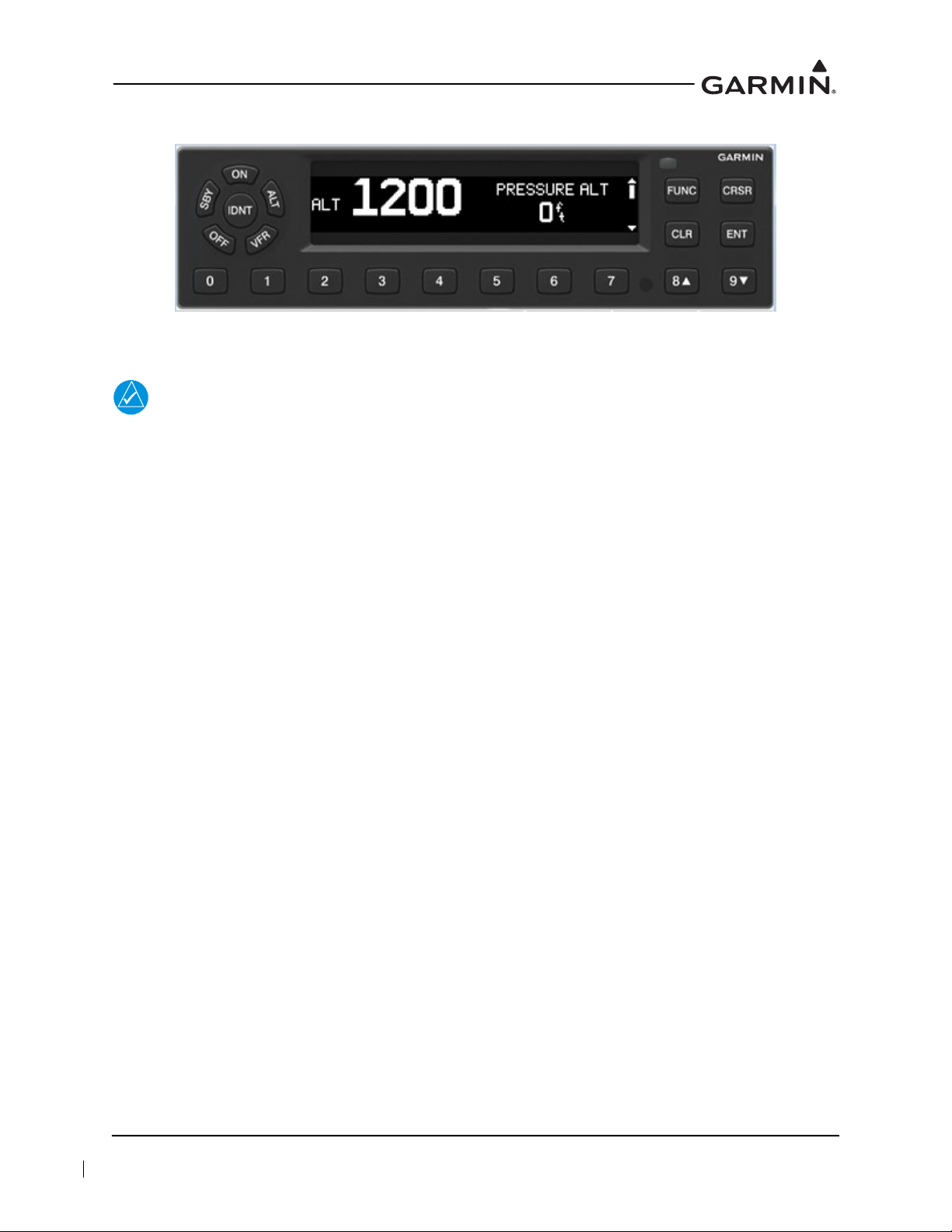
3.1 GTX 335/345
Figure 3-1 GTX 335/345 Front Panel
Function Selection Keys
NOTE
If the transponder is in the ON or ALT operating mode, the transponder becomes an active
part of the Air Traffic Control Radar Beacon System (ATCRBS). The transponder
responds to interrogations from TCAS-equipped rotorcraft.
The function selection keys are:
OFF Powers off the GTX 3X5.
STBY Selects the Standby mode. Pressing the STBY key when the GTX 335/345 is powered off
automatically powers the unit on in Standby mode. When in Standby mode, the transponder
does not reply to interrogations (but new codes can be entered) and a “SBY” indication
appears on the display.
ON Selects the On mode, which generates Mode A and Mode S replies, but Mode C altitude
reporting is inhibited. Pressing the ON key when the GTX 335/345 is powered off
automatically powers on the unit in Mode A and will transmit a squawk code when
interrogated. ADS-B Out will not return barometric altitude as it switches to GPS altitude in
this mode. Interrogations are indicated by the reply symbol (®). The replies do not include
altitude information.
ALT Altitude mode is automatically selected when the rotorcraft becomes airborne using the unit’s
Air/Ground logic or when the ALT key is pressed. Pressing the ALT key when the
GTX 335/345 is powered off automatically powers on the unit in Altitude Reporting mode.
While the rotorcraft is on the ground and in ALT mode, the transponder does not allow
Mode A and Mode C replies, but it does permit acquisition squitter and replies to Mode S
interrogations.
While the rotorcraft is in ALT mode and airborne, it will generate Mode A, Mode C, and
Mode S replies, as well as transmit acquisition and extended squitter, including ADS-B Out.
All transponder interrogations are indicated by the reply symbol (®).
IDENT Pressing the IDENT key activates the Special Position Identification (SPI) pulse for
18 seconds, identifying the transponder return from others on an air traffic controller’s screen.
During the IDENT period, the word “IDENT” appears in the upper-left corner of the display.
VFR Sets the transponder code to the pre-programmed VFR code selected in Configuration mode
(set to 1200 at the factory). Pressing the VFR key again restores the previous identification
code.
190-00734-21 GTX 3X5 Part 27 AML Maintenance Manual
Rev. 2 Page 3-2
Page 24

FUNC In Normal mode, pressing the FUNC key changes the subpage group shown on the right side
of the display. Subpages include Flight ID, Pressure Altitude, Flight Time, Altitude Monitor,
System Count Up, and Count Down Timers. In Configuration mode, it steps through the
function pages.
ENT Confirms entry for selected item and moves the cursor to the next editable item, or function
selection, in configuration and normal operation. Starts and stops the altitude monitor, count
up, count down, and flight timers.
CRSR Selects changeable fields in configuration and normal operation. Initiates entry of the starting
time for the count down timer and cancels transponder code entry. Holding the CRSR key
during power-up will place the unit into a Ground Test mode that forces the rotorcraft into an
airborne status for testing purposes.
CLR Resets the count up, count down, and flight timers. Cancels the previous key press during code
selection, count down entry, or flight ID entry. Used in Configuration mode to scroll through
the function pages.
8 Used as a scroll-up key to navigate through page groups in Normal and Configuration mode.
9 Used as a scroll-down key to navigate through page groups in Normal and Configuration
mode.
Code Selection
Code selection is entered with eight keys (0 through 7) providing 4,096 active identification codes.
Pushing one of these keys begins the code selection sequence. The new code is not activated until the
fourth digit is entered. Pressing the CLR key moves the cursor back to the previous digit. Pressing the
CLR key when the cursor is on the first digit of the code, or pressing the CRSR key during code entry,
removes the cursor and cancels data entry, restoring the previous code. The numbers 8 and 9 are not used
for code entry, only for flight ID entry, count down time, rotorcraft tail number entry, and data selection in
Configuration and Normal mode.
Configuration Mode
To enter Configuration mode, press and hold the ENT key, then energize the unit. To exit Configuration
mode, press and hold the OFF key until the unit de-energizes.
To cycle through the pages, press the FUNC key
To access items on the page, press the CRSR key
To cycle through the selections of an item on the page, press the 8 or 9 key
To scroll up or down on the page when nothing is selected, press the 8 or 9 key
To move within the page, press the ENT key
To move to previous selection on the page, press the CLR key
To exit the page, press the FUNC key
GTX 3X5 units may also be configured using the GTX 3X5 Install Tool. For configuration using the
GTX 3X5 Install Tool, refer to Section 3.3.
190-00734-21 GTX 3X5 Part 27 AML Maintenance Manual
Rev. 2 Page 3-3
Page 25

Function Display
FLIGHT ID If Allow Pilot to Edit Flt ID is configured to YES, the flight ID can be changed
by the pilot at any time in Normal mode. This allows the pilot/crew to enter
the specific flight ID for transmission to ATC interrogations.
UP COUNTER Timer controlled by ENT and CLR keys.
DOWN COUNTER Timer controlled by ENT, CLR, and CRSR keys. The initial count down time
is entered with the 0 through 9 keys.
FLIGHT TIMER Displays the flight time, controlled by the ENT key or by one of four airborne
sources (squat switch, GPS ground speed recognition, air data airspeed
recognition, or altitude increase), as configured during installation. The timer
begins when the GTX 3X5 determines that the rotorcraft is airborne.
TRIP TIMER Timer controlled by ENT and CLR keys.
PRESSURE ALT Displays the altitude data supplied to the GTX 3X5 in feet, hundreds of feet
(flight level), or meters, depending on configuration.
ALT MONITOR Controlled by ENT key. Activates a voice alarm and warning annunciator
when altitude limit is exceeded.
SAT/DALT Displayed when the GTX 3X5 is configured with temperature input. Displays
Static Air Temperature and Density Altitude.
CONTRAST/OFFSET Contrast is controlled by the 8 and 9 keys.
BACKLIGHT/OFFSET This page is only displayed if photocell backlighting mode is selected in
Configuration mode. Backlighting is controlled by the 8 and 9 keys.
MESSAGES Alerts crew of transponder faults, fails, and advisory messages. “MSG”
appears when a message is generated. CRSR and ENT keys access messages
for acknowledgment and viewing.
BLUETOOTH This page is only shown on the GTX 345 when configured for Bluetooth at
installation. When selected, it allows PEDs to pair to the GTX 345 and device
management to show ADS-B In data.
INTERNAL GPS This page displays Lat/Long accuracy, number of connected satellites,
horizontal figure of merit, whether the unit is using internal GPS, and overall
status.
1090ES TX CTRL This is only displayed when the unit is configured for 1090ES Out Control in
Configuration mode to be Pilot Set. Once configured, this can be highlighted
by the CRSR key, changed by the 8 and 9 keys, and selected by ENT key.
Turns the extended squitter function on or off.
190-00734-21 GTX 3X5 Part 27 AML Maintenance Manual
Rev. 2 Page 3-4
Page 26

3.2 GTX 335R/345R
Figure 3-2 and Figure 3-3 show the GTX control pages associated with the GTN 6XX/7XX. Refer to the
specific pilot’s guide and cockpit reference guide for details regarding control and function. Part numbers
for these documents are listed in Table 1-1.
Figure 3-2 GTN 7XX Transponder Control
Figure 3-3 GTN 6XX Transponder Control
190-00734-21 GTX 3X5 Part 27 AML Maintenance Manual
Rev. 2 Page 3-5
Page 27
3.3 GTX 3X5 Install Tool
86%$ 86%%
NOTE
If the GTX 3X5/3X5R is configured to interface with a display control unit, the display
control unit must be turned off or in Configuration mode prior to running the GTX 3X5
Install Tool.
NOTE
The GTX 3X5 Install Tool pages shown within this manual reflect GTX 3X5 Install Tool
version 2.05. Some differences in operation may be observed when comparing information
in this manual to later versions of the install tool.
The GTX 3X5 Install Tool is available for download from the Garmin Dealer Resource Center
GTX 3X5 Install Tool requires a computer with available USB 2.0 ports and Microsoft Windows XP or
later.
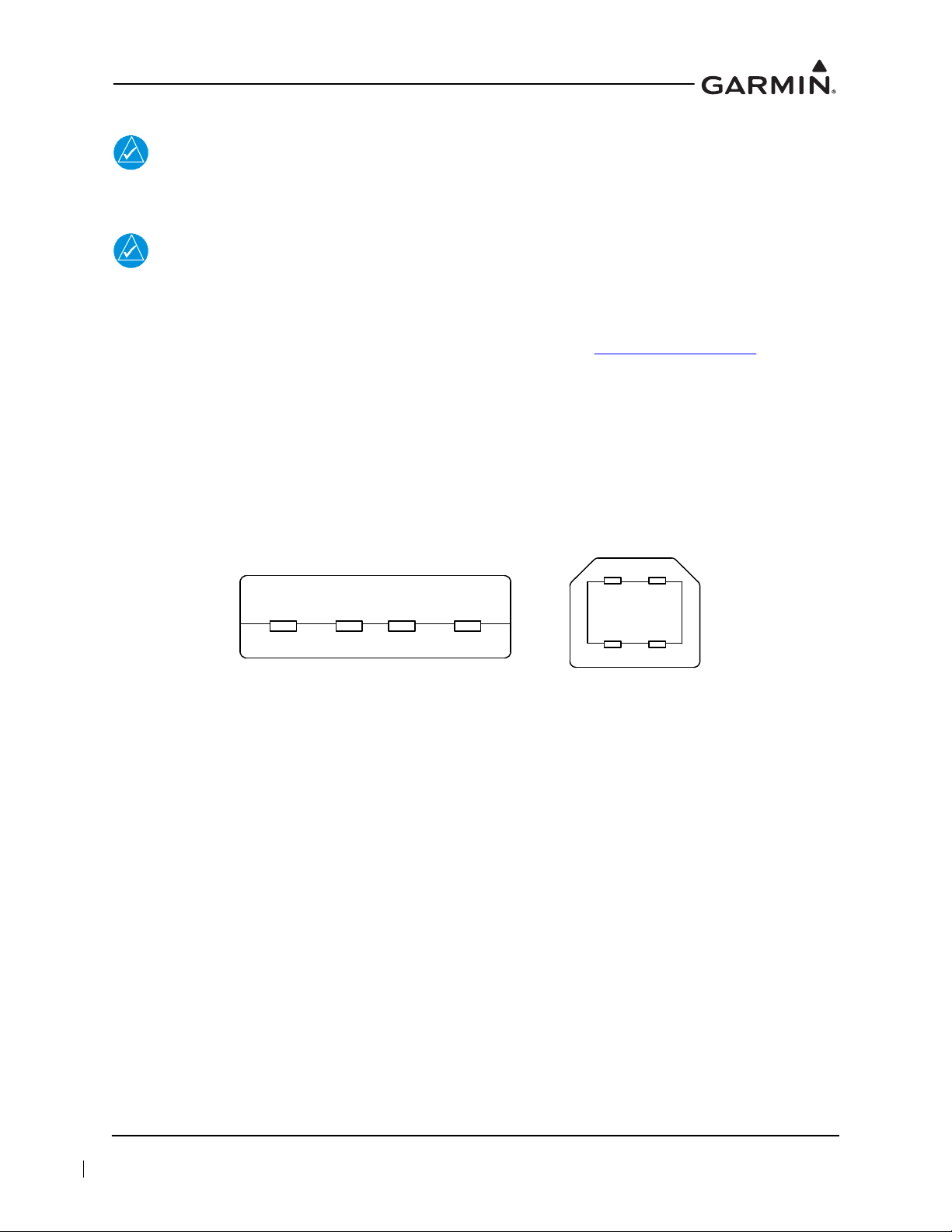
A USB A-to-B cable is required to interface between a computer and the GTX 3X5/3X5R. For additional
details, refer to Figure 3-4. To use the GTX 3X5 Install Tool:
1. Remove power from the GTX 3X5/3X5R.
2. Remove power from the display control unit or verify it is in Configuration mode.
3. Connect the USB cable between the GTX 3X5 and the computer.
4. Energize the GTX 3X5/3X5R and run the GTX 3X5 Install Tool.
Figure 3-4 USB A and USB B Connectors
The install tool is used to check equipment status, load software, and configure the unit.
To place a GTX 3X5/3X5R unit in Configuration mode:
1. In the Unit Mode window, change “Normal Mode” to “Configuration Mode.”
2. Click the Set key.
. The
Green boxes indicate a function operating correctly. Red boxes indicate a failure. Yellow boxes indicate a
fault or warning. Gray boxes indicate the presence of a message.
The bottom of the install tool displays unit information, such as software version, connection status, and
unit mode. The tool will annunciate if alerts, faults, failures, or warnings exist. The menu bar at the top of
the install tool has a GTX key and a Help key. The GTX key provides the following options:
• Save configuration
• Load configuration
• Reset configuration
• Push configuration from install tool to configuration module
• Exit
190-00734-21 GTX 3X5 Part 27 AML Maintenance Manual
Rev. 2 Page 3-6
Page 28
The Help key provides the following information:
• Part number
• Version number
• Copyright statement
• Software license agreements
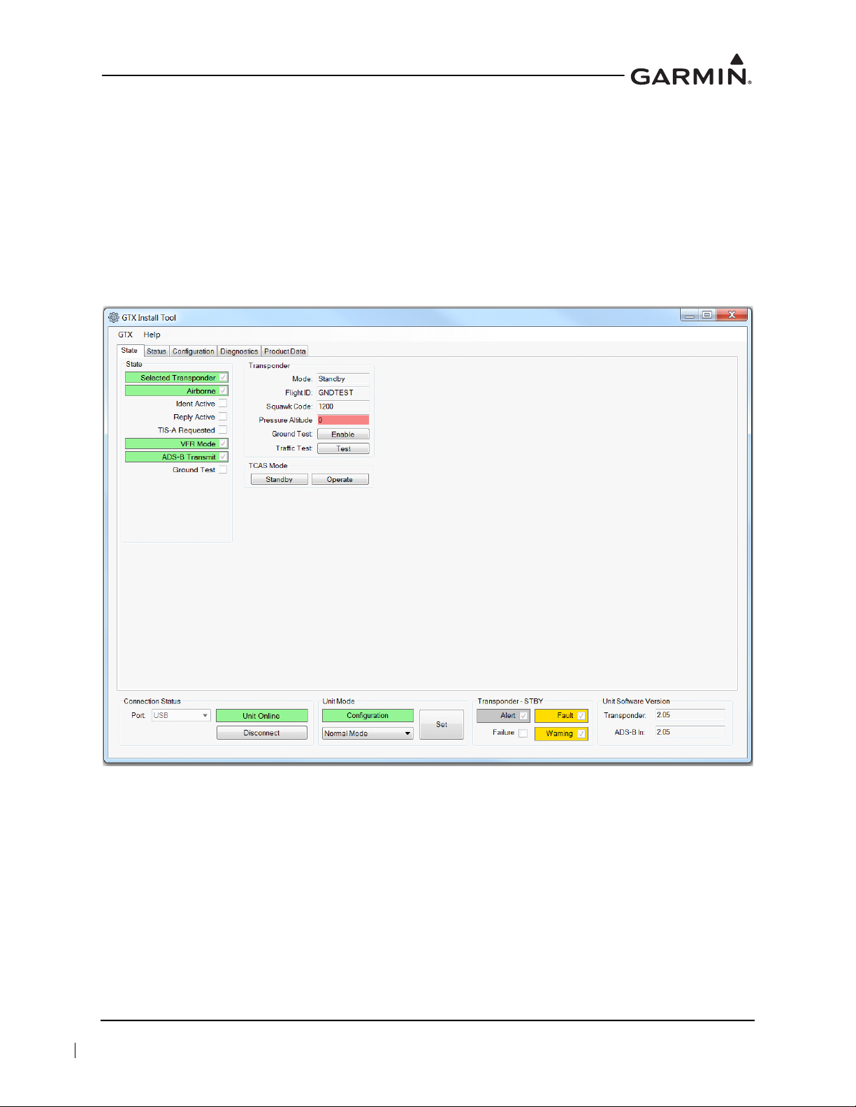
3.3.1 State Page
The State page of the GTX 3X5 Install Tool reports the current mode of the GTX 3X5/3X5R, Flight ID,
Squawk Code, and Pressure Altitude. Mode selections include Ground Test and Traffic Test modes.
Standby and Operate test modes are also provided for TCAS.
Figure 3-5 GTX 3X5/3X5R State Page
190-00734-21 GTX 3X5 Part 27 AML Maintenance Manual
Rev. 2 Page 3-7
Page 29
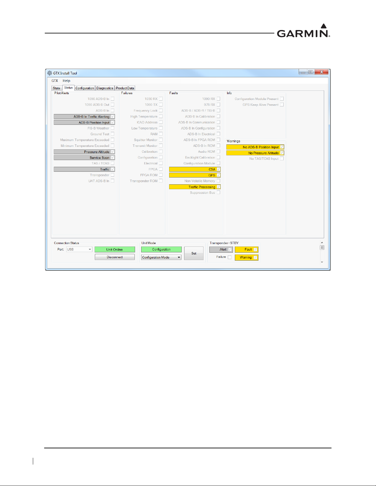
3.3.2 Status Page
The Status page reports failures, faults, warnings, and pilot alerts. Information such as whether there is a
configuration module present is also displayed.
Figure 3-6 GTX 3X5/3X5R Status Page
190-00734-21 GTX 3X5 Part 27 AML Maintenance Manual
Rev. 2 Page 3-8
Page 30
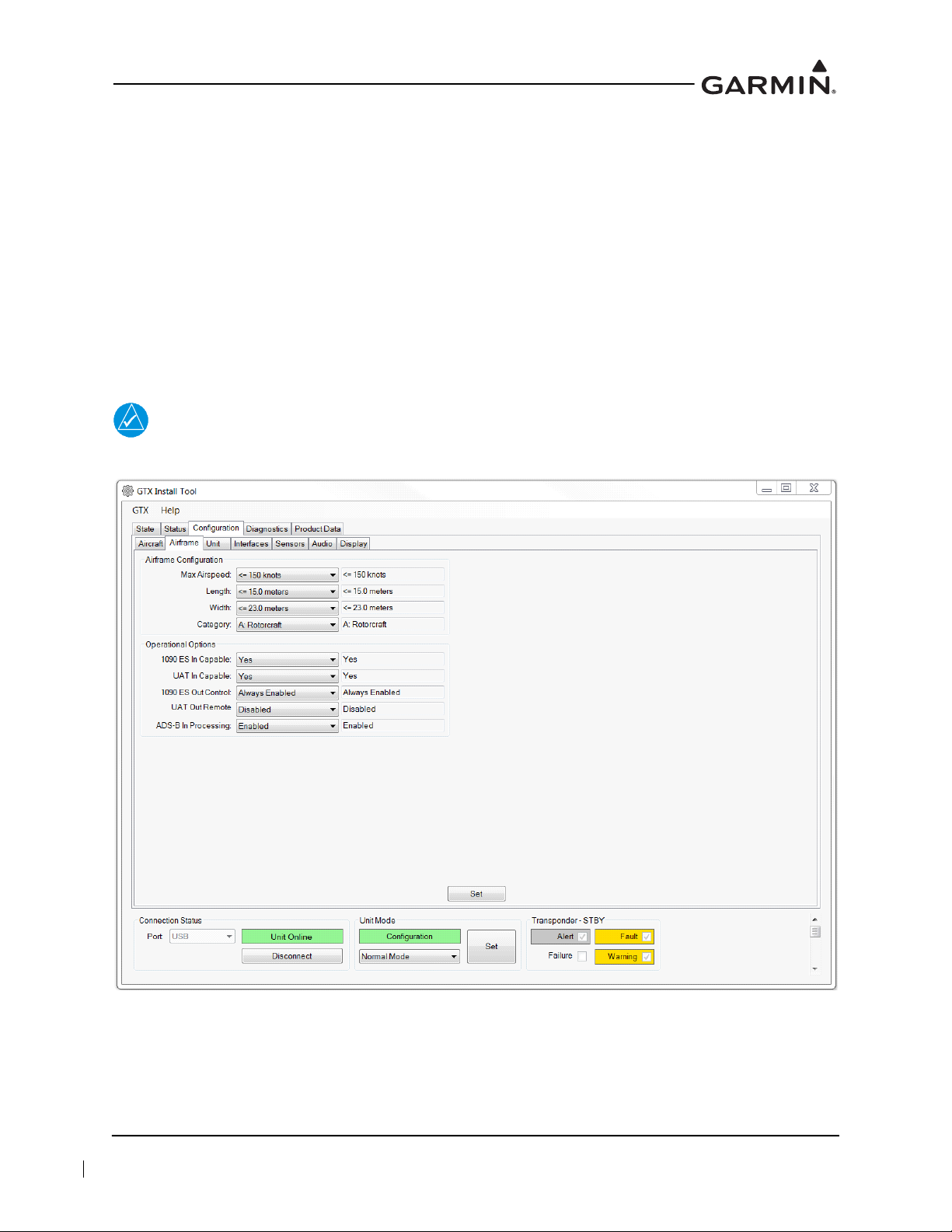
3.3.3 Configuration Group
The Configuration group contains the following pages:
Aircraft page – allows the configuration of basic aircraft configuration and flight ID settings
Airframe page – allows the configuration of basic airframe configuration and operational options
settings
Unit page – allows the configuration of identification code, unit options, and display options
Interfaces page – allows the configuration of serial, A429, discretes, and HSDB settings
Sensors page – allows the configuration of Garmin Altitude Encoder, GPS, internal AHRS, and
additional sensors
Audio page – allows the configuration of audio options and alerts
Display page – allows the configuration of display and key backlight, photocell and lighting bus
curves, and default offsets
NOTE
All configurable settings must match the GTX System Configuration Log retained in the
rotorcraft permanent records.
Figure 3-7 GTX 3X5/3X5R Configuration Group
190-00734-21 GTX 3X5 Part 27 AML Maintenance Manual
Rev. 2 Page 3-9
Page 31

3.3.4 Diagnostics Group
NOTE
GTX 3X5/3X5R must be in Configuration mode to view connection status or get assert log.
The Diagnostics group contains the following pages:
DAP page – reports the status of the necessary data supporting ADS-B requirements
Discretes page – reports the status of discrete inputs, outputs, and allows the user to override the
output pins for testing purposes
Connection Status page – reports the status of A429 inputs, serial inputs, and HSDB
Internal GPS page – reports GPS acquisition status and signal strength
Bluetooth page – reports Bluetooth receiver status and paired devices
Assert Log page – provides the ability to download assert log for system troubleshooting
Figure 3-8 GTX 3X5/3X5R Diagnostics Group
190-00734-21 GTX 3X5 Part 27 AML Maintenance Manual
Rev. 2 Page 3-10
Page 32

3.3.5 Product Data Group
The product data group provides the following pages.
Transponder page – displays basic system, FPGA, boot block, and audio database information
ADS-B In page – displays basic system, FPGA, and boot block information
GPS page – displays GPS and GPS loader information
Garmin Altitude Encoder page – displays the altitude encoder serial number
Configuration page – displays the configuration status of aircraft, unit, wiring, and display CRCs
Figure 3-9 GTX 3X5/3X5R Product Data Group
3.3.6 Software Upload Group
Allows GTX 3X5/3X5R software updates. Refer to Section 7.2 for details.
190-00734-21 GTX 3X5 Part 27 AML Maintenance Manual
Rev. 2 Page 3-11
Page 33

4 INSTRUCTIONS FOR CONTINUED AIRWORTHINESS
4.1 Applicability .....................................................................................................................................4-2
4.2 Airworthiness Limitations ................................................................................................................4-3
4.3 Servicing Information.......................................................................................................................4-4
4.3.1 On Condition Servicing..............................................................................................................4-4
4.3.2 Special Tools..............................................................................................................................4-4
4.4 Maintenance/Inspection Intervals.....................................................................................................4-5
4.5 Visual Inspection ..............................................................................................................................4-6
4.5.1 GTX 335/345 Visual Inspection ................................................................................................4-6
4.5.2 GTX 335R/345R Visual Inspection...........................................................................................4-7
4.5.3 Antenna Visual Inspection .........................................................................................................4-7
4.5.4 Post-Lightning Strike Inspection................................................................................................4-8
4.5.5 Post-Hard Landing Inspection....................................................................................................4-8
4.6 Electrical Bonding Test ....................................................................................................................4-9
4.7 Additional Instructions .....................................................................................................................4-9
This section provides Instructions for Continued Airworthiness for the GTX 3X5 with ADS-B installation.
This section satisfies the requirements for continued airworthiness as defined by 14 CFR Part 27.1529 and
Part 27 Appendix A. Procedures and practices defined in this section are required to maintain the
continued airworthiness of the GTX 3X5 as installed per STC SR02124SE.
190-00734-21 GTX 3X5 Part 27 AML Maintenance Manual
Rev. 2 Page 4-1
Page 34

4.1 Applicability
This document applies to all rotorcraft equipped with GTX 3X5 units with ADS-B per STC SR02124SE.
Modification of a rotorcraft by this Supplemental Type Certificate (STC) obligates the helicopter operator
to implement the specific maintenance practices and/or airworthiness limitations provided in this
document. This is in addition to the rotorcraft’s existing approved maintenance, inspection, and
airworthiness limitations programs.
Appendix Sections A.1 through A.6 must be filled out by the installer, included as part of FAA Form 337,
and filed with the rotorcraft’s permanent records. These appendices document GTX 3X5 installation
details that are essential to system maintenance and are a part of the rotorcraft Instructions for Continued
Airworthiness. These include:
General rotorcraft and GTX transponder specific information
Electrical Load Analysis
Equipment connected to the installed GTX transponder
Configuration log of the installed GTX transponder(s) (a printout of the GTX 3X5 configuration
from the GTX 3X5 Installation Tool is also acceptable)
Location of the GTX 3X5 transponder and connected antenna(s) as installed in the rotorcraft,
including all wire routing
190-00734-21 GTX 3X5 Part 27 AML Maintenance Manual
Rev. 2 Page 4-2
Page 35

Page 36

4.3 Servicing Information
GTX 3X5 LRU maintenance is “on condition” only.
4.3.1 On Condition Servicing
Servicing or replacement may be required if the GTX 3X5/3X5R exhibits symptoms, failures, or alerts as
described in this manual.
4.3.2 Special Tools
The following tools are required to perform the tasks described in this manual:
Calibrated milliohm meter with an accuracy of +
Calibrated transponder ramp tester
Calibrated pitot-static ramp tester
GTX 3X5 Install Tool
50 Ω 5 watt antenna load
0.1 mΩ or better
190-00734-21 GTX 3X5 Part 27 AML Maintenance Manual
Rev. 2 Page 4-4
Page 37

4.4 Maintenance/Inspection Intervals
NOTE
The intervals listed in the table below must be adhered to for each installed GTX.
Table 4-1 shows systems and components, installed by this STC that must undergo tests or checks at
specific intervals. The inspections based on calendar elapsed time have specifically-stated intervals.
Table 4-1 Maintenance/Inspection Intervals
Item Description/Procedure Section Interval
Equipment
removal and
re-installation
Cleaning
Removal and re-installation of GTX LRUs.
The GTX 335/345 display and bezel may be
cleaned periodically.
Cleaning is accomplished using a soft cotton
cloth dampened with clean water.
Do not use any chemical cleaning agents.
Avoid scratching the surface of the display.
6
N/A
On Condition
On Condition
Antenna visual
inspection
Lightning strike actual or
suspected
Testing
Equipment visual
inspection
Testing
Electrical
bonding test
Hard landing
Removal and replacement.
Inspect the coaxial cable connections, GTX
bonding hardware (including bonding straps
and tape), antenna, and surrounding areas.
The GTX 3X5 receiver sensitivity must be
tested and shown to comply with Title 14 CFR
Part 43 Appendix F.
The GTX 3X5 must be tested and shown to
comply with Title 14 CFR Part 91.227.
A visual inspection of the equipment installed
by this STC must be performed.
The GTX 3X5 must be tested and shown to
comply with Title 14 CFR Part 91.411, 91.413,
and Part 43 Appendices E and F.
An electrical bonding test must be performed
on equipment installed by this STC.
Inspect the GTX, mounting rack, and rotorcraft
structure.
4.5
4.5
8.4.2
8.4.3
4.5
8.4.2
4.6
4.5.5
On Condition
On Condition
On Condition
Replacement of GPS
Position source(s)
12 Calendar Months
Refer to Title 14 CFR
Part 91.411, 91.413,
and Part 43
Appendices E and F
10 Years or
2000 hours
On Condition
190-00734-21 GTX 3X5 Part 27 AML Maintenance Manual
Rev. 2 Page 4-5
Page 38

4.5 Visual Inspection
Perform a visual inspection in accordance with requirements in this section. Check for corrosion, damage,
or other defects for each of the installed items. Replace any damaged parts as required. Inspection may
require temporary removal of a unit or units to gain access to connectors. For equipment removal and
replacement, refer to Section 6. For equipment locations, refer to Appendix A. For instructions on
removing access panels, consult the specific rotorcraft maintenance manual.
4.5.1 GTX 335/345 Visual Inspection
During normal rotorcraft inspections, but not to exceed 12 calendar month intervals, conduct a visual
inspection of the GTX 335/345 installation in the following locations:
Instrument Panel or Console
1. Inspect all GTX 335/345 keys for legibility of labels and markings.
2. Inspect GTX 335/345 unit(s) for security of attachment.
3. Inspect GAE (if installed) for security of attachment.
4. Inspect GTX rack and fasteners for integrity.
a. The racks, fasteners, and support structure must be in good condition and the fasteners secured
properly.
b. There must be no corrosion.
5. Inspect any bonding straps for corrosion, loose connections, or signs of damage. Refer to
Appendix B for details.
6. Inspect the condition of the wiring harnesses and coaxial cables.
a. Inspect all GTX and adjacent wiring and coax for chafing, damage, proper routing of wire
bundles, and security of attachment in accordance with AC 43.13-1B, Chapter 11, Section 8,
paragraph 11-96. Pay particular attention to possible areas of chafing.
b. Verify that the GTX and adjacent wiring show no signs of cracking, chafing, abrasion,
melting, or any other form of damage.
c. Inspect the GTX rack and LRU connectors for corrosion or other defects. Check the integrity
of the shield block ground attachments to the harness connector assembly, as well as the
integrity of the individual shields and their attachment.
190-00734-21 GTX 3X5 Part 27 AML Maintenance Manual
Rev. 2 Page 4-6
Page 39

4.5.2 GTX 335R/345R Visual Inspection
During normal rotorcraft inspections, but not to exceed 12 calendar month intervals, conduct a visual
inspection of the GTX 335R/345R installation in the following locations:
Remote Mount Rack
1. Inspect GTX 335R/345R unit(s) for security of attachment.
2. Inspect GAE (if installed) for security of attachment.
3. Inspect GTX rack and fasteners for integrity.
a. The racks, fasteners, and support structure must be in good condition and the fasteners
properly secured.
b. There must be no corrosion.
c. For a composite shelf, aluminum foil tape used to ground the GTX must not be torn, damaged,
or corroded. If any of these occur, the tape must be replaced. Refer to Appendix B for details.
4. Inspect any bonding straps for corrosion, loose connections, or signs of damage. Refer to
Appendix B for details.
5. Inspect the condition of the wiring harnesses and coaxial cables.
a. Verify that all GTX wiring and cables are securely fastened.
b. Verify that the GTX and adjacent wiring show no signs of cracking, chaffing, abrasion,
melting, or any other form of damage.
c. Inspect the GTX rack and LRU connectors for corrosion or other defects. Check the integrity
of the shield block ground attachments to the harness connector assembly, as well as the
integrity of the individual shields and their attachment.
4.5.3 Antenna Visual Inspection
During normal rotorcraft inspection, but not to exceed 12 calendar months, visually inspect the transponder
antenna(s) for the following:
1. Erosion of the antenna blade leading edge, cracks, dents, or other physical damage. If any of these
conditions are present, the antenna must be replaced. For antenna replacement details, refer to the
antenna manufacturer’s instructions.
2. Secure attachment of the antenna to the rotorcraft structure. If the attachment is not secure,
re-work the installation and complete the electrical bonding test, as described in the applicable
antenna installation instructions.
3. Condition of the environmental seal at the base of the antenna. A damaged or compromised seal
must be replaced and the electrical bonding tested, as described in the applicable antenna
installation instructions.
190-00734-21 GTX 3X5 Part 27 AML Maintenance Manual
Rev. 2 Page 4-7
Page 40

4.5.4 Post-Lightning Strike Inspection
An inspection must be performed following a suspected or actual lightning strike to antennas or any
sensor(s) connected to the GTX unit. The antenna, sensor, and rotorcraft structure to which they are
mounted must be inspected for physical damage, particularly the location(s) where lightning may have
attached. If visible physical damage is present, the antenna and sensor must be replaced.
The coax cable connecting the antenna to the GTX unit must be inspected, including grounding fasteners,
bonding straps, or aluminum tape. The rotorcraft structure supporting the installation of the remotely
mounted GTX must be inspected to verify that no physical damage has occurred. If damaged, the structure
must be repaired in accordance with the model-specific rotorcraft structural repair manual or the rotorcraft
manufacturer’s instructions. Damaged components must be replaced, followed by completion of the
electrical bonding test described in Section 4.6.
4.5.5 Post-Hard Landing Inspection
An inspection must be performed following a hard landing. The GTX, mounting rack, and rotorcraft
structure to which they are mounted must be inspected for physical damage, particularly the location(s) of
the mounting hardware. If visible physical damage is present, the GTX, mounting rack, and rotorcraft
structure must be replaced or repaired in accordance with the model-specific rotorcraft structural repair
manual or the rotorcraft manufacturer’s instructions. Any component repair or replacement must be
followed by completion of the electrical bonding test described in Section 4.6.
190-00734-21 GTX 3X5 Part 27 AML Maintenance Manual
Rev. 2 Page 4-8
Page 41

4.6 Electrical Bonding Test
1. Disconnect all connectors from the GTX 3X5. This includes the antenna coaxial cable.
2. Measure the DC resistance between the aircraft ground and the metal case of the GTX 3X5.
Verify that the resistance is less than or equal to 10 mΩ.
NOTE
Any grounding straps or aluminum foil added as part of the GTX 3X5 installation for
grounding the GTX to the airframe ground must be included in the measurement.
3. If the resistance is more than 10 mΩ, the electrical bond must be improved such that the direct
current resistance, when measured with a 4-wire meter, is less than or equal to 2.5 mΩ. For
instructions on how to create a new electrical bond, refer to Appendix B.
4.7 Additional Instructions
Electrical load information for the GTX is provided in Section 2.3.
190-00734-21 GTX 3X5 Part 27 AML Maintenance Manual
Rev. 2 Page 4-9
Page 42

5 TROUBLESHOOTING
5.1 GTX General Troubleshooting.........................................................................................................5-2
5.2 GTX Failure Annunciations..............................................................................................................5-4
5.3 Connector Pinout Information ........................................................................................................5-14
5.3.1 GTX 3X5..................................................................................................................................5-14
5.3.2 Altitude Functions....................................................................................................................5-17
5.3.3 Discrete Functions....................................................................................................................5-18
5.3.4 RS-232 Input/Output................................................................................................................5-20
5.3.5 ARINC 429 Input/Output.........................................................................................................5-20
5.3.6 RS-422 Out...............................................................................................................................5-20
5.3.7 HSDB Input/Output..................................................................................................................5-21
190-00734-21 GTX 3X5 Part 27 AML Maintenance Manual
Rev. 2 Page 5-1
Page 43

5.1 GTX General Troubleshooting
This section provides information to assist troubleshooting if problems occur after completing
maintenance. Refer to the GTX System Configuration Log retained in the rotorcraft permanent records for
a list of the interfaced equipment and system configuration data. When troubleshooting the GTX, refer to
the wire routing drawings and interconnect wiring diagrams that are retained in the rotorcraft permanent
records.
The following diagram describes possible symptoms associated with the Garmin transponders and
provides corresponding actions for troubleshooting.
190-00734-21 GTX 3X5 Part 27 AML Maintenance Manual
Rev. 2 Page 5-2
Page 44
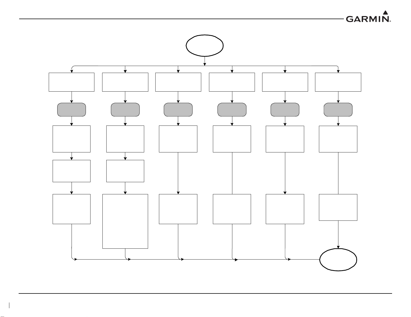
Chec k and verify t he
integrity of the
trans ponder -altitude
encod er interf ace,
inc luding w iring and
alt itu de encoder
operat ion
Chec k and ve rify
integrity of the
antenna ins tallat ion,
ground planes , and
coaxial cable
Ensure the XPDR
cir cuit breaker is
closed
Tes t coaxial cables for
ins ertio n loss and V SW R.
VS WR should be check ed
with an in-line type VSWR/
wat tmeter inserte d in the
coax ial tra nsm is si on l ine
betw een the transpo nder and
the ant enna. The VS WR
shoul d be 1.5:1 at 1090 MH z
or le ss . Inserti on los s shoul d
be less than 1.5 dB at
1090 M Hz
GTX Sym ptom
Transponder audio too
quiet/loud
Incorrec t Mode S aircraft
data tra nsmitted
Transponder will not turn
on
Transponder will not come
out of standb y
Chec k for pro per
elec tric al bondi ng/
grounding of t he
antenna ins tallat ion
Co rrecti ve
Action
Co rrecti ve
Action
Co rrecti ve
Action
Cor recti ve
Action
Ensure transponder
is fully seated and
mated to the
connectors in the
mounting rack
Corrective
Action
Corrective
Action
If fault still exists,
contact Garmin.
Loss of, or inco rrect altitude
reporti ng by the tran sponde r
Verify transp onder
sel ect swi tc h posi tion ,
(#1 or #2) if installed
Chec k th e
conf iguration mode
settings and reset if
necessary
Verify that the GTX
volume setting is at or
above the minimum
required set ting
Poor transponder
performance. Weak or
intermittent radar contact
reported by ATC
Verify connections
for power and groun d
Verify t he u nsw itched
audio input at the
audio panel sett ing is
at o r ab ove the
minimum required
setting
Chec k the alti tude
sourc e conf igurat ion
on the GTX. Verify
primary and secondary
sourc es are configur ed
properly
Verify the Flight ID and
ICAO address are
conf igured proper ly
Verify t he Tail num ber
and I C AO address are
properly conf igured
Figure 5-1 GTX Transponder Troubleshooting (All Models)
190-00734-21 GTX 3X5 Part 27 AML Maintenance Manual
Rev. 2 Page 5-3
Page 45

5.2 GTX Failure Annunciations
GTX 3X5 Messages
If fault still exists,
contact Garmin.
Transponder
OR
1090 ADS-B
Out
1090 MHz
Transmitter
Failure
1030 MHz
Receiv er Failure
Failure
ICAO Address
Failure
Loss, damaged,
incorrec t wiring
Incorrect antenna
Internal failure
ICAO address is
incorrec t
Caus e
Verify transponder
antenna,
co nnections , and
coax ins tallation
Inspect
suppression bus
wiring
Inspect wiring
Reload software
Reset config and
config module
Re-configur e u nit
Verify t ransponder
antenna,
connections, and
coax inst allation
Inspect
suppression bus
wiring
Inspect wiring
Reload soft ware
Reset config and
config module
Re-configur e u nit
Enter proper ICAO
address
Reload software
Corrective
Action
Transponder
OR
1090 ADS-B
Out
Failure
Caus e
Loss, damaged,
incorrect w iring
Incorrect antenna
Internal failure
Corrective
Action
Transponder
OR
1090 ADS-B
Out
Failure
Caus e
Corrective
Action
Configuration
Failure
Transponder
configuration data
is invalid or
incomplete
Reload softw are
Reset con fig and
config module.
Re-configur e u nit
Verify the GTX
Install Tool
configuration
summary, correct
any errors
Transponder
OR
1090 ADS-B
Out
Failure
Caus e
Corrective
Action
Calibration
Failure
Factory
transponder
calibration data
invalid
Reload softw are
Reset config and
config module
Re-configure unit
Verify t ransponder
antenna,
connections, and
coax inst allaiton
Inspect wiring,
suppression bus,
and connections
Transponder
OR
1090 ADS-B
Out
Failure
Cause
Corrective
Action
Electrical Fa ilure
Internal voltage
mis-compare with
the unit
Reload softw are
Reset config and
config module.
Re-configure unit
Verify all wi ring,
shorts/opens.
Verify power and
ground
connections
Transponder
OR
10 90 AD S-B
Out
Failure
Cause
Corrective
Action
Frequency Lock
Failure
FPGA has
an error.
Possible internal
hardware i ssue
Reload softw are
Reset config and
config module.
Re-configure unit
Verify t ransponder
antenna,
connections, and
coax inst allation
Inspect wiring,
suppression bus,
and connections
Transponder
OR
1090 ADS-B
Out
Failure
Cause
Corrective
Action
Squitter Monitor
Failure
Error generating
squitter replies.
Possible internal
hardware i ssue
Reload softw are
Reset config and
config module
Re-configure unit
Verify t ransponder
antenna,
connections, and
coax inst allation
Inspect wiring,
suppression bus,
and connections
Transponder
OR
1090 ADS-B
Out
Failure
Cause
Corrective
Action
Reset config and
config module.
Re-configur e u nit
190-00734-21 GTX 3X5 Part 27 AML Maintenance Manual
Rev. 2 Page 5-4
Figure 5-2 GTX 3X5 Transponder Alerts
Sheet 1 of 5
Page 46

GTX 3X5 Messages
If fault still exists,
contact Garmin.
Transmit M onitor
Failure
FPGA Failure
- 1090 MHz
transmission
failures
- Internal hardware
problem
- Wiring problem
- Incompatible
antenna
FPGA software did
not load properly
Relo ad software
Reset config and
config module.
Re-configure unit
Verify antenna,
connections, and
coax installation
Inspect wiring,
suppression bus,
and connections
Reload software
Re set co nfi g and
config module.
Re-configure unit
Verify antenna,
connections, and
coax installation
Inspect wiring,
suppression bus,
and connections
Transponder
OR
1090 ADS-B
Out
Transponder
OR
1090 ADS-B
Out
Failure
Failure
Cause
Cause
Corrective
Action
Corrective
Action
Maximum
Temperature
Exceeded
Minimum
Temperature
Exceeded
Low Temperature
Failure
High
Temperature
Failure
Inte rnal
Temperature has
exceeded limits;
Possible internal
damage may have
occured
Bring GTX within
operating
temperature listed
on the EQF
Bring GTX within
operating
temperature listed
on the EQF
Int ern al
Temperature has
exceeded limits;
Possible internal
damage may have
occured
Failure Failure
Cause Cause
Corrective
Action
Corrective
Action
High
Temperature
Failure
Low Temperature
Failure
Internal
Temperature has
exceeded limits;
possible internal
damage may have
occurred
Bring GTX within
operating
temperature listed
on the EQF
Bring GTX within
operating
temperature listed
on the EQ F
Inte rnal
Temperature has
exceeded limits;
possible internal
damage may have
occurred
Transponder
OR
1090 ADS-B
Out
Transponder
OR
1090 ADS-B
Out
Failure Failure
Cause Cause
Corrective
Action
Corrective
Action
RAM Failure
Software load
issue or internal
hardware issue
Reload software
Transponder
OR
1090 ADS-B
Out
Failure
Cause
Corrective
Action
Transponder
FPGA ROM
Failure
FPGA software
load issue
Reload software
Transponder
OR
1090 ADS-B
Out
Failure
Cause
Corrective
Action
Transponder
ROM Failure
Software load
issue
Reload software
Transponder
OR
1090 ADS-B
Out
Failure
Cause
Corrective
Action
Reset config and
confi g module.
Re-configure unit
Reset config and
config module.
Re-configure unit
Reset config and
confi g module.
Re-configure unit
Figure 5-2 GTX 3X5 Transponder Alerts
Sheet 2 of 5
190-00734-21 GTX 3X5 Part 27 AML Maintenance Manual
Rev. 2 Page 5-5
Page 47

GTX 3X5 Messag es
If f ault st ill ex ists,
contact Garmin.
Pre ss ure
Altitude
Pressure
Alt itude Inpu t
Warni ng
Gr ound Tes t
Ground Test
Mode
Pres sure altitude
is not v alid
Verify G TX and
pres sure senso r are
properly configured
Verify wir ing from
pres sure senso r
Verify pr essure
sensor is functioning
If using the GAE,
ver ify connect ions
and then r ecalibrate
Reload softw are
System in Ground
Tes t mode
Power cy cle the GTX
Warning
Cause
Correct ive
Action
Alert
Cause
Corrective
Action
TAS/TCAS
TAS/TCAS
Input Warning
TAS/TCAS is configured
on the GTX and no data
is received or the
TAS/TCAS system is
reporting a failure
Verify TAS/T CAS
sys tem has the r equired
and v alid data
(i.e. Position, Altitude,
Headin g, etc.)
Verify w iring with
TAS/TCAS system
Verify t he TAS/TCAS is
configured properly
Verify th e TAS/TCAS
sy stem ha s not failed
Warning
Cause
Co rrect ive
Action
ADS-B
Position Input
No ADS-B
Position Input
Warni ng
GPS position
unavailable with ADS -B
In and/ or O ut enabled.
(for ADS-B O ut, the unit
is n ot in Standby )
Verify GPS antenna is
SBAS compatible
Verify pos ition s ource is
available, powered on,
and properly configured
Verify G PS antenna
has clear v iew of the
sky
War ning
Cause
Correct ive
Action
Res et co nfig and
config module.
Re-c onfigur e unit
ADS-B In
Traffic
Alerting
CSA Fault
Traffic
Tra ffic
Processing
Fault
Traffi c
ADS-B In
Communication
Fault
ADS -B In pr ocess ing is enabled and
the input data doe s not me et the
perf ormanc e spec ifications .
- GPS horizontal position unavailable
- GPS v elocit y un availa ble
- GPS time u navailable
- HF OM mus t be better than 0.5N M
- Pressure altitude unav ailable or GPS
altitude and VFOM worse than 45m
Verify valid GPS antenna has
clear view of th e sk y
Posit ion s ource is availab le,
properly configured and powered
Verify AD S -B In traffic is pro perly
ins talled a nd c onfigur ed, d isplay
sou rce, heading so urce, GPS
source are all configured
properly
Reset configuration and
configuration module, then re -
configure unit
Reload so ftware
ADS-B In is enabled and an additional
fault has occured.
- ADS -B / ADS -R / TIS -B Fault
- T AS/TCAS Input W arning
-CSA Fault
-GPS Fault
- P ress ure Altitude Warni ng
- ADS-B In Elec trical Fault
- Internal communication between the
main and ADS -B boards
Ins pect co mpatibilit y of
transponder ant enna and
conn ections
Verify the po sition s ource is
ava ilable, powered on and
properly configured
Reset configur ation and
configuration module, then
re-configur e unit
Reload s oftware
Verify T AS/TCAS sy stem is
not failed
ADS-B In is enabled and an additional
fault has occured.
- ADS-B / AD S -R / TIS-B F ault
- TAS/T CAS Input Warning
- C SA F aul t
- GPS Fault
- Pressure Altitude Warning
- ADS-B In Electrica l Fault
- Internal c ommunication betwe en the
main and ADS -B boards
Faul t
Cause
Co rrect ive
Action
Fault Fault
Cause Cause
Correc tive
Action
Co rrect ive
Action
Inspec t compatibility of
tran sponder antenna and
connections
Rese t configur ation and
configuration module, then
re- configu re unit
Reload so ftware
Verify TAS/TCAS system is
not failed
Verify the pos ition so urce is
avai lable, p owered o n, and
properly configured
190-00734-21 GTX 3X5 Part 27 AML Maintenance Manual
Rev. 2 Page 5-6
Figure 5-2 GTX 3X5 Transponder Alerts
Sheet 3 of 5
Page 48

GTX 3X5 Messages
If fault still exists,
contact Garmin.
ADS-B IN
ADS-B/ADS-R/
TIS-B Fault
1090
ADS-B In
1090 RX Fault
UAT
ADS-B In
978 RX Fault
ADS-B In enabled
and both 1090 MHz
and 978 MHz
receivers fa iled
Verify antenna is
compatible
Reload software
Inspect all wiring
and coaxial cables
ADS-B In enabled
and the 1090 MHz
receiver failed
Verify antenna is
compatible
Reload software
Inspect all wiring,
and coaxial cables
ADS-B In enabled
and the 978 MHz
receiver fa iled
Inspect
compatibility of
transponder
antenna and
connections
Reload software
Fault
Cause
Correctiv e
Action
Fault
Cause
Corrective
Action
Fault
Cause
Corrective
Actio n
FIS-B
Weather
978 RX Fault
FIS-B
Weather
ADS-B In
Communication
Fault
FIS-B enabled
and the 978 MHz
receiver failed
Inspect
compatibility of
transponder
antenna and
connections
FIS-B enabled and
the 978 MHz
receiver f ailed
Inspect
compatibility of
transponder
antenna and
connections
Reload software
Fault
Cause
Corrective
Action
Fault
Cause
Correctiv e
Actio n
ADS-B In
Configuration
Fault
ADS-B In
configuration data
did not load or is
invalid
Service Soon
Fault
Cause
Corrective
Actio n
ADS-B In
Electrical Fault
ADS-B In
Calibr ation
Fault
Reload software
Electrical fault with
the ADS-B board.
Possible internal
hardware problem
Check wiring
Factory ADS-B In
calibrat ion data is
invalid
Reload software
Service Soo nService Soon
Fault
Cause
Fault
Cause
Corrective
Action
Corrective
Actio n
Reset config and
config module.
Re-configure unit
Reset config and
config module
Reconfigure unit
Reset config and
config module.
Re-configure unit
Reset config and
config module.
Re-configur e unit
Reset config and
config module.
Re-configure unit
Reset config and
config module.
Re-configure unit
Reload software
Reset config and
config module.
Re-configure unit
Reset config and
config module.
Re-configure unit
Reload software
190-00734-21 GTX 3X5 Part 27 AML Maintenance Manual
Rev. 2 Page 5-7
Figure 5-2 GTX 3X5 Transponder Alerts
Sheet 4 of 5
Page 49

GTX 3X5 Messages
If fault stil l exi sts,
contac t G armin.
GPS Fault
GAE
Cali bration
Fault
Backlight
Cali brati on
Fault
Configuration
Mo dul e Fa ult
No GPS data
available
Internal GPS fault
Not connected to
a va lid SBAS/
GPS source
Verify GPS
antenna is SBAS
com patib le
Verify posi tion
source is avail able
and properly
configured
Verify GPS
antenna has clear
view of the sky
Garmin Altitude
Encoder (GAE)
calibration data is
inva lid
Calibrate GAE
Factory calibration
for the di splay is
inv alid
Verify lighting
configuration
Failure of the
configuration
module
Verify module is
installed and
wiring is correct
Service SoonService Soon
Fault
Caus e
Fault
Cause
Service Soon Service Soon
Fault
Cause
Fault
Cause
Corrective
Action
Corrective
Action
Corrective
Action
Corrective
Action
Audio ROM
Fault
Non-volatile
Mem ory Fau lt
Audio database
did not load or is
inv alid
Non-volatile data
did not load or is
inv alid
Service SoonService Soon
FaultFault
CauseCause
Corrective
Action
Corrective
Action
Service Soon
Suppressio n
Bus Fault
Fault on the
suppression bus
Ch eck fo r
inc ompati ble LRU
on suppression
line (DME)
Verify suppr ession
bus wiring for
shorts or opens
Fault
Cause
Corrective
Action
ADS-B In
FPGA ROM
Fault
ADS-B In FPGA
software di d not
load or is invalid
Service Soon
Fault
Caus e
Corrective
Action
Reset config and
config module.
Re-configur e unit
ADS-B In
ROM Fault
ADS-B In software
did not load or is
inv alid
Reload software
Service Soon
Fault
Caus e
Corrective
Action
Reset config and
config module.
Re-configur e unit
Reset config and
config module.
Re-configure unit
Reset config and
config module.
Re-configure unit
Reload software Reload software Reload software
Reset config and
config module.
Re-configur e unit
Reload software
Re set co nfig and
config module.
Re-configur e unit
Reload software
Reset config and
config module.
Re-configure unit
Reload software
Figure 5-2 GTX 3X5 Transponder Alerts
Sheet 5 of 5
190-00734-21 GTX 3X5 Part 27 AML Maintenance Manual
Rev. 2 Page 5-8
Page 50

GTX 3X5 Install Tool
Fail ure Messages
If fault still exists,
cont ac t G armin.
RAM Failure
Squitter Monitor
Failure
Cause
High Temperature
Failure
Cause
Corrective
Action
The main board or
transmitter board
temperature is
above 80° C.
Allow the unit to
cool down to less
than 70
° C.
Frequency Lock
Failur e
Cause
The units
synthesizer
cannot lock the
desired
frequency.
Re-ins tall transponder
soft ware and
conf iguration.
Software did not install
correctly. Possible
internal memory
damage.
Corrective
Acti on
Low Temperature
Failure
Cause
Corrective
Actio n
The main board or
transmitter board
temperature is
below -45° C.
Allow the unit to
warm up to
greater than
-35
° C.
Calibration Failure
Configuration
Failure
FPGA Failure
FPGA ROM
Failur e
Transponder
ROM Failure
Software did not
install correctly.
Pos sibl e int ernal
memory damage.
Corrective
Actio n
Re-ins tall transponder
soft ware and
conf iguration.
Cause
Elec trical Failure
Figure 5-3 GTX 3X5 Install Tool Failure/Fault Messages
Sheet 1 of 5
190-00734-21 GTX 3X5 Part 27 AML Maintenance Manual
Rev. 2 Page 5-9
Page 51

978 RX Fault*
Cause
Correcti ve
Action
GTX 3X5 In stall Tool
Failure Me ssages
ICAO Address
Failu re
Cause
If fault still exists,
contact Garmin.
Bad cable connection.
Correcti ve
Action
Verif y ant enna cable i s
not disconnected ,
damaged, or all owing
pin t o shield contact.
Cause
Transmit
Monit or Failure
ICAO address is all
ones or zeros.
Corrective
Acti on
Enter correct ICAO
address.
1090 RX Fault*
Cause
The 1090 M Hz receiver has
fail ed the 1090 MHz receive
test.
Correcti ve
Action
Inspect cables and
connections to
transponder anten na.
Note:
*For GTX 345 only.
1090 TX Failure
Sup pr es sion Bu s
Fau lt
Cause
Inspect transponder
antenna, suppression
bus cable s, and
connectors.
Loose, damaged, or
incorr ect wirin g.
Possible internal
failure.
Cor rec tive
Acti on
1030 RX Failure
The 978 M Hz receiver has
fail ed t he 978 MHz receive
test.
Inspect cables and
connections to
transponder ant enna.
ADS-B In
Communication
Fau lt*
Cause
Corrective
Action
There is an internal
communication failure
between the main board
and the A DS-B board.
Relo ad ADS- B
Software.
190-00734-21 GTX 3X5 Part 27 AML Maintenance Manual
Rev. 2 Page 5-10
Figure 5-3 GTX 3X5 Install Tool Failure/Fault Messages
Sheet 2 of 5
Page 52

Re-install main and
ADS-B software.
GTX 3X5 I nstall Tool
Failure Messages
ADS-B In processing is enabled and any of t he
following are t rue:
- Posit ion is unavailable
- Inst alled TA S/ TCAS system is report ing f ailed
(the 1090 M Hz receiver has f ailed the 1090 MHz
receiver t est AND the 978 MHz receiver ha s
failed t he 978 MHz receiver t est)
- Int ernal ADS-B board power failure has been
detected
Cause
Corrective
Action
If fault still exists,
contact Garmin.
ADS-B/ADS-R/
TIS-B Fault*
Cause
Corrective
Action
The 1090 MHz
receiver has failed the
1090 MHz receiver
test AND The 9 78
MHz re ce ive r has
failed the 978 MHz
receiver test.
Inspect cables
and connections
to transponder
antenna.
Re-install main
and A DS-B
software.
CSA Fault*
Cause
Corrective
Acti on
The input data does
not meet required
performance
specifications or is
invalid.
No ADS-B
Position Input
Warning
Cause
Corrective
Acti on
ADS-B In and/or
Out is enabled
and position is
unavailable.
Ensure position
source is available,
properly
configured, and
powered on.
Ensu re GPS
antenna has a
clear, unobstructed
view of the sky.
No TAS/TCAS
Input Warning*
Cause
Corrective
Acti on
No messages have
been received from an
installed TAS/TCAS
system or the system
is reporting failed.
Inspect
connections to
TAS/TCAS
system. Ensure
TAS/TCAS
system is
functioning
properly.
Note:
*For GTX 345 only.
Traffic
Processing
Fau lt*
No Pressure
Altitude Warning
Cause
Corrective
Acti on
Pressure altitude
is invalid.
Inspect
connections to
pressure sensor.
Verify pressure
sensor is
functioning
properly.
Figure 5-3 GTX 3X5 Install Tool Failure/Fault Messages
Sheet 3 of 5
190-00734-21 GTX 3X5 Part 27 AML Maintenance Manual
Rev. 2 Page 5-11
Page 53

GTX 3X5 Install Tool
Failure Messages
If fault still exists,
contact Garmin.
ADS-B In
Configuration
Fault*
ADS-B In ROM
Fault*
Cause
Test Mode
Cause
Corrective
Action
Unit is operating in
Test mode.
Reload transponder
and ADS-B software.
Check configuration
settings.
The GTX 3X5 has
detected a fault during
the internal power -up
integ rity check.
Correct ive
Action
ADS-B In FPGA
ROM Fault*
Audio ROM Fault
Nonvolatile
Memory Fault
Unit is in
Ground Test
mode .
Correct ive
Action
For installer use only.
Cycle power on GTX.
Cause
Ground Test
Mode
GPS Fault
Cause
Inspect cables and
connections to GPS
antenna. Ensure GPS
antenna has clear,
unobstructed view of sky.
The GTX 3X5 has
detected a fault during
the internal power-up
integrity check.
Corrective
Action
ADS-B In
Electrical Fault*
Note:
*For GTX 345 only.
190-00734-21 GTX 3X5 Part 27 AML Maintenance Manual
Rev. 2 Page 5-12
Figure 5-3 GTX 3X5 Install Tool Failure/Fault Messages
Sheet 4 of 5
Page 54

ADS-B In
Calibration Data
Fault*
Backlight
Calibration Fault
Cause
The GTX 3X5 has
detected a fault during
the internal power-up
integrity check.
Corrective
Action
GAE Calibration
Fault
Configuration
Module Fault
GTX 3X5 Install Tool
Failure Messages
Contact Garmin.
Note:
*For GTX 345 only.
Figure 5-3 GTX 3X5 Install Tool Failure/Fault Messages
Sheet 5 of 5
190-00734-21 GTX 3X5 Part 27 AML Maintenance Manual
Rev. 2 Page 5-13
Page 55

5.3 Connector Pinout Information
59 58 57 56
5
5
54 53 52 51 434450 49 48 47 46 45
62
61
60
25 24 23 22
262728293031323334
3536373839
404142
1
23
45
67891011131415
1617
12
192021 18
5.3.1 GTX 3X5
Figure 5-4 Rear View, Connector J3251
Table 5-1 J3251 Pinout
Pin GTX 3X5 Pin Name I/O
1 ALT ENCODER/CONFIG MODULE CLOCK I/O
2 USB DATA HI I/O
3 TEMP PROBE IN IN
4 TIME MARK A I/O
5 ARINC 429 OUT A OUT
6 ARINC 426 OUT B OUT
7 RS-232 OUT 3 OUT
8 RS-232 OUT 2 OUT
9 RS-232 OUT 1 OUT
10 ALITTUDE A1 IN
11 ALTITUDE B1 IN
12 ALTITUDE C1 IN
13 ALTITUDE D4 IN
14 EXTERNAL STANDBY SELECT IN
15 CONFIGURABLE DISCRETE 1 I/O
16 CONFIGURABLE DISCRETE 2 I/O
17 XPDR FAIL 1 OUT
18 EXTERNAL SUPPRESSION I/O
19 LIGHTING BUS HI IN
20 ROTORCRAFT GROUND IN
21 ROTORCRAFT POWER 1 IN
22 ALT ENCODER/CONFIG MODULE DATA I/O
23 ALT ENCODER/CONFIG MODULE GND IN
24 USB DATA LO I/O
25 TEMP PROBE OUT OUT
26 TIME MARK B I/O
27 ARINC 426 IN 1A IN
28 ARINC 429 IN 1B IN
29 RS-232 IN 3 IN
190-00734-21 GTX 3X5 Part 27 AML Maintenance Manual
Rev. 2 Page 5-14
Page 56

Pin GTX 3X5 Pin Name I/O
30 RS-232 IN 2 IN
31 RS-232 IN 1 IN
32 ALTITUDE A2 IN
33 ALTITUDE B2 IN
34 ALTITUDE C2 IN
35 RESERVED IN
36 EXTERNAL IDENT SELECT IN
37 AUDIO INHIBIT 2 IN
38 POWER CONTROL IN
39 SWITCHED POWER OUT OUT
40 LIGHTING BUS LO IN
41 ROTORCRAFT GROUND --
42 ROTORCRAFT POWER 1 --
43 ALT ENCODER/CONFIG MODULE POWER --
44 USB VBUS POWER I/O
45 USB GND --
46 AUDIO OUT HI OUT
47 AUDIO OUT LO OUT
48 ARINC 429 IN 2A IN
49 ARINC 429 IN 2B IN
50 RS-232 GND 3 --
51 RS-232 GND 2 --
52 RS-232 GND 1 --
53 ALTITUDE A4 IN
54 ALTITUDE B4 IN
55 ALTITUDE C4 IN
56 ALTITUDE GROUND --
57 SQUAT SWITCH IN
58 AIR DATA SELECT IN
59 POWER CONFIG IN
60 GPS KEEP ALIVE --
61 ROTORCRAFT POWER 2 --
62 ROTORCRAFT POWER 2 --
190-00734-21 GTX 3X5 Part 27 AML Maintenance Manual
Rev. 2 Page 5-15
Page 57

Figure 5-5 Rear View, Connector J3252
5 4 3 2 1
10 9 8 7 6
15 14 13 12 11
Table 5-2 J3252 Pinout
Pin GTX 345/345R Pin Name I/O
1 ETHERNET OUT 1B OUT
2 ETHERNET IN 1B IN
3 ETHERNET OUT 2B OUT
4 ETHERNET IN 2B IN
5 RS-232 OUT 4 OUT
6 ETHERNET OUT 1A OUT
7 ETHERNET IN 1A IN
8 ETHERNET OUT 2A OUT
9 ETHERNET IN 2A IN
10 RS-232 IN 4 IN
11 RS-422 A OUT
12 RS-422 B OUT
13 CONFIGURABLE DISCRETE 11 I/O
14 CONFIGURABLE DISCRETE 12 I/O
15 RS-232 GND 4 --
190-00734-21 GTX 3X5 Part 27 AML Maintenance Manual
Rev. 2 Page 5-16
Page 58

5.3.2 Altitude Functions
Gillham code altitude inputs are considered active if either the voltage to ground is < 1.9 V or the
resistance to ground is < 375 Ω. These inputs are considered inactive if the voltage to ground is
11-33 VDC. The GTX 3X5/3X5R discrete I/O pins are configurable. If the Gillham input is not enabled in
the configuration menu, then the Gillham code altitude pins can be used for other discrete input functions.
If the Gillham input is enabled, these pins will not be available for selection on other discrete inputs in the
configuration menu.
Table 5-3 GTX 3X5/3X5R Encoded Altitude Pin Assignments
Pin Pin Name I/O Connector
13 ALTITUDE D4 IN J3251
10 ALTITUDE A1 IN J3251
32 ALTITUDE A2 IN J3251
53 ALTITUDE A4 IN J3251
11 ALTITUDE B1 IN J3251
33 ALTITUDE B2 IN J3251
54 ALTITUDE B4 IN J3251
12 ALTITUDE C1 IN J3251
34 ALTITUDE C2 IN J3251
55 ALTITUDE C4 IN J3251
56 ALTITUDE COMMON -- J3251
190-00734-21 GTX 3X5 Part 27 AML Maintenance Manual
Rev. 2 Page 5-17
Page 59

5.3.3 Discrete Functions
Discrete Outputs
Table 5-4 GTX 3X5/3X5R Discrete Outputs
Pin Pin Name I/O
17 TRANSPONDER FAIL 1 OUT All J3251
18 EXTERNAL SUPPRESSION I/O All J3251
X REPLY ACTIVE OUT All J3251/J3252
X TRANSPONDER FAIL #2 OUT All J3251/J3252
X ALTITUDE ALERT* OUT All J3251/J3252
X EQUIPMENT STATUS OUT All J3251/J3252
X TRAFFIC ALERT OUT 345/345R J3251/J3252
X TRAFFIC STANDBY OUT 345/345R J3251
X TRAFFIC TEST OUT 345/345R J3251
X TCAD SENSITIVITY OUT 345/345R J3251/J3252
* INACTIVE: 10 ≤ Vin ≤ 33 VDC or Rin ≥ 100 kΩ (Open)
ACTIVE: V
Sink current is internally limited to 200 uA max for a grounded input.
X Denotes that this discrete output can be configured to any available discrete output pin on either the
J3251 or J3252 connectors. Refer to Table 5-5 for a list of configurable output pins.
≤ 1.9 VDC with ≥75 uA sink current, or Rin ≤ 375 Ω (GND)
in
Unit (335/345/
335R/345R)
Connector
Table 5-5 GTX 3X5/3X5R Configurable Output Pins
Pin Pin Name I/O
17 TRANSPONDER FAIL #1 OUT All J3251
15 CONFIGURABLE DISCRETE #1 I/O All J3251
16 CONFIGURABLE DISCRETE #2 I/O All J3251
13 CONFIGURABLE DISCRETE #11 I/O 345/345R J3252
14 CONFIGURABLE DISCRETE #12 I/O 345/345R J3252
Unit (335/345/
335R/345R)
Connector
190-00734-21 GTX 3X5 Part 27 AML Maintenance Manual
Rev. 2 Page 5-18
Page 60

Discrete Inputs
Table 5-6 GTX 3X5/3X5R Discrete Inputs
Pin Pin Name I/O
X TIS-A SELECT* IN 335/335R J3251
X ALTITUDE SOURCE* IN All J3251/J3252
X AUDIO INHIBIT #1* IN All J3251/J3252
37 AUDIO INHIBIT #2* IN All J3251
58 AIR DATA SOURCE* IN All J3251
57 SQUAT IN All J3251
36 IDENT* IN All J3251
14 STANDBY* IN All J3251
13 INSTALL ID SELECT IN All J3251
18 EXTERNAL SUPPRESSION I/O I/O All J3251
* INACTIVE: 10 ≤ Vin ≤ 33 VDC or Rin ≥ 100 kΩ (Open)
ACTIVE: V
Sink current is internally limited to 200 uA max for a grounded input.
X Denotes that this discrete input can be configured to any available discrete input pin on either the
J3251 or J3252 connectors. Refer to Table 5-7 for a list of configurable input pins.
≤ 1.9 VDC with ≥75 uA sink current, or Rin ≤ 375 Ω (GND)
in
Unit (335/345/
335R/345R)
Connector
Table 5-7 GTX 3X5/3X5R Configurable Input Pins
Pin Pin Name I/O
37 AUDIO INHIBIT #2 IN All J3251
58 AIR DATA SELECT IN All J3251
57 SQUAT SWITCH IN All J3251
36 EXTERNAL IDENT IN All J3251
14 EXTERNAL STANDBY IN All J3251
18 EXTERNAL SUPPRESSION I/O I/O All J3251
15 CONFIGURABLE DISCRETE #1 I/O All J3251
16 CONFIGURABLE DISCRETE #2 I/O All J3251
13 CONFIGURABLE DISCRETE #11 I/O 345/345R J3252
14 CONFIGURABLE DISCRETE #12 I/O 345/345R J3252
Unit (335/345/
335R/345R)
Connector
190-00734-21 GTX 3X5 Part 27 AML Maintenance Manual
Rev. 2 Page 5-19
Page 61

5.3.4 RS-232 Input/Output
Table 5-8 GTX 3X5/3X5R RS-232 Connections
Pin Pin Name I/O
9 RS-232 OUT 1 OUT All J3251
31 RS-232 IN 1 IN All J3251
8 RS-232 OUT 2 OUT All J3251
30 RS-232 IN 2 IN All J3251
7 RS-232 OUT 3 OUT All J3251
29 RS-232 IN 3 IN All J3251
5 RS-232 OUT 4 OUT 345/345R J3252
10 RS-232 IN 4 IN 345/345R J3252
Unit (335/345/
335R/345R)
5.3.5 ARINC 429 Input/Output
Table 5-9 GTX 3X5/3X5R ARINC 429 Connections
Pin Pin Name I/O
27 ARINC 429 IN 1A IN All J3251
Unit (335/345/
335R/345R)
Connector
Connector
28 ARINC 429 IN 1B IN All J3251
5 ARINC 429 OUT 1A OUT All J3251
6 ARINC 429 OUT 1B OUT All J3251
48 ARINC 429 IN 2A IN All J3251
49 ARINC 429 IN 2B IN All J3251
5.3.6 RS-422 Out
Table 5-10 GTX 3X5/3X5R RS-422 Connections
Pin Pin Name I/O
11 RS-422 A OUT 345/345R J3252
12 RS-422 B OUT 345/345R J3252
Unit (335/345/
335R/345R)
Connector
190-00734-21 GTX 3X5 Part 27 AML Maintenance Manual
Rev. 2 Page 5-20
Page 62

5.3.7 HSDB Input/Output
Table 5-11 GTX 345/345R HSDB Connections
Pin Pin Name I/O
6 ETHERNET OUT 1A OUT 345/345R J3252
7 ETHERNET IN 1A IN 345/345R J3252
1 ETHERNET OUT 1B OUT 345/345R J3252
2 ETHERNET IN 1B IN 345/345R J3252
8 ETHERNET OUT 2A OUT 345/345R J3252
9 ETHERNET IN 2A IN 345/345R J3252
3 ETHERNET OUT 2B OUT 345/345R J3252
4 ETHERNET IN 2B IN 345/345R J3252
Unit (335/345/
335R/345R)
Connector
190-00734-21 GTX 3X5 Part 27 AML Maintenance Manual
Rev. 2 Page 5-21
Page 63

6 UNIT REMOVAL AND RE-INSTALLATION
6.1 GTX 3X5 ..........................................................................................................................................6-2
6.1.1 GTX 335/345 Panel-Mounted Units ..........................................................................................6-8
6.1.2 GTX 3X5R with Horizontal Install Rack.................................................................................6-11
6.1.3 GTX 3X5R with Vertical Install Rack.....................................................................................6-13
6.1.4 Garmin Altitude Encoder .........................................................................................................6-15
6.2 Transponder Antenna......................................................................................................................6-17
6.3 Traffic Annunciator (If Installed) ...................................................................................................6-17
190-00734-21 GTX 3X5 Part 27 AML Maintenance Manual
Rev. 2 Page 6-1
Page 64

6.1 GTX 3X5
GTX 3X5
GTX 345/345R Only
P3252
1
2
4
3
2
5
7
4
2
6
This section contains parts, procedures, and requirements for assembly, removal, and re-installation of
GTX 3X5 equipment installed under STC SR02124SE. After removal and re-installation, the GTX 3X5
return to service procedures must be performed in accordance with Section 9. After re-installation of the
GTX 3X5, verify that the electrical bond is equal to or less than 2.5 mΩ, per Section 4.6.
Table 6-1 GTX 3X5 Connector Kit
Item Description P/N Qty
1 Connector, hi-dense, D-Sub, mil crimp 62 ckt
2 Sub-assembly, backshell with hardware, 37/62 pin
3 Sub-assembly, ground adapter, shell 4&5
4 Screw, 4-40 X 0.250, FLHP 100, SS/P, nylon
5 Connector, hi-dense, D-Sub, mil crimp, 15 ckt
6 Sub-assembly, backshell with hardware, 9/15 pin
7 Sub-assembly, ground adapter, shell 1-3
330-00185-62
011-00950-03
011-01169-01
211-63234-06
330-00185-15
011-00950-00
011-01169-00
1
1
1
2 ea connector
1
1
1
P3251
Figure 6-1 GTX 3X5 Connector Kits
190-00734-21 GTX 3X5 Part 27 AML Maintenance Manual
Rev. 2 Page 6-2
Page 65

For a list of the backplate items associated with the standard mounting assembly, refer to Table 6-2. For
3
1
2
NUT SUPPLIED
WITH ITEM 2
5
4
detailed drawings of the backplate assembly, refer to Figure 6-2 and Figure 6-3.
Table 6-2 Standard Mount Backplate (P/N 011-02976-00 and -01)
Item Description P/N Qty
DCP, connector plate, GTX 3X5, w/secondaries
1
Connector, male/female special, BNC
2
Washer, shoulder, GNC 400
3
Connector, male/female, special, BNC/TNC
4
Screw, 4-40 X 0.250, PHP, SS/P, nylon
5
125-00307-10 1
330-00053-01 1
212-00022-00 2
330-00053-02 1
211-60234-08 4
Figure 6-2 GTX 3X5 without GPS Backplate Assembly
(P/N 011-02976-00)
190-00734-21 GTX 3X5 Part 27 AML Maintenance Manual
Rev. 2 Page 6-3
Page 66
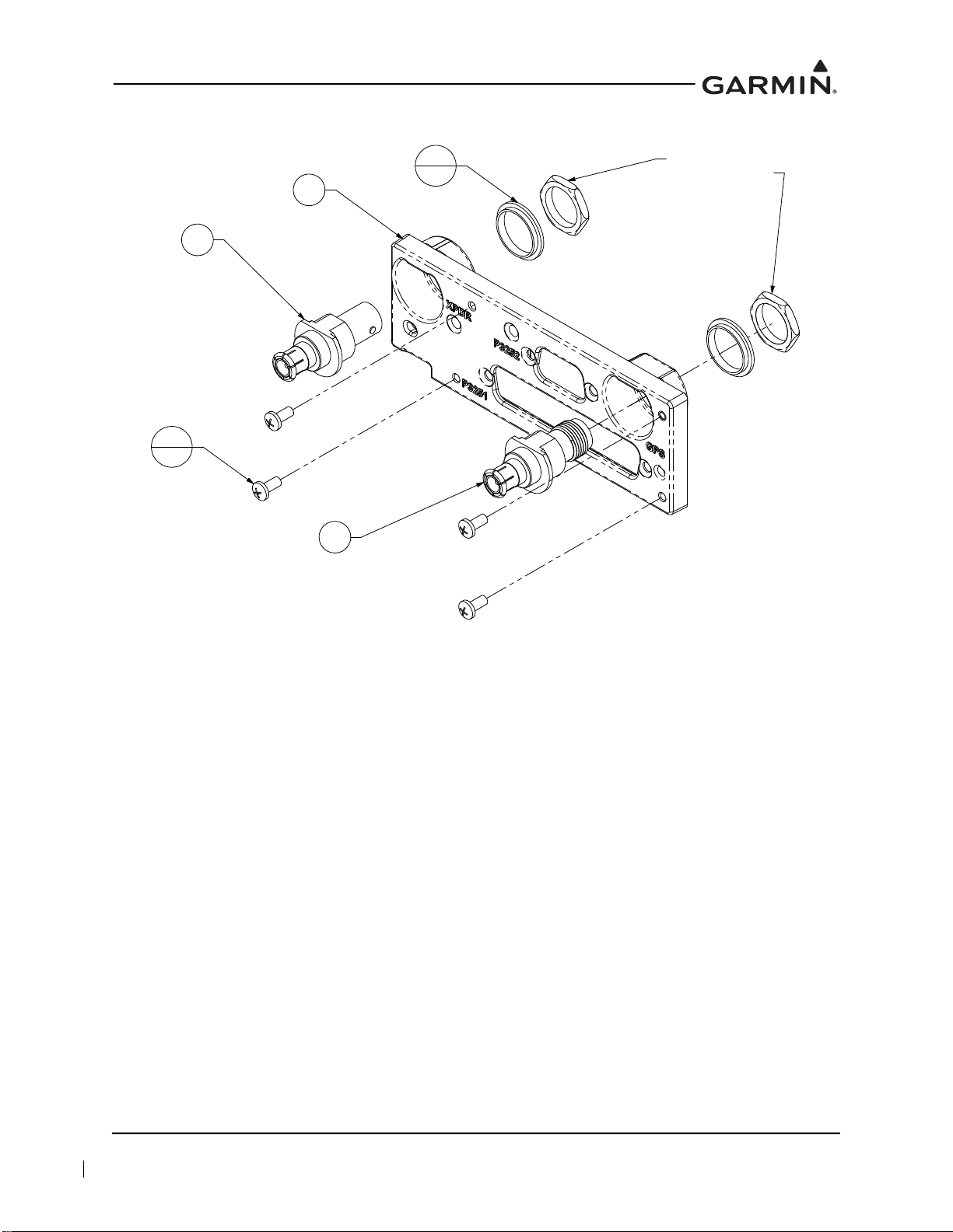
Figure 6-3 GTX 3X5 with GPS Backplate Assembly
1
2
4
3
2
NUTS SUPPLIED
WITH ITEMS 2 & 4
5
4
(P/N 011-02976-01)
190-00734-21 GTX 3X5 Part 27 AML Maintenance Manual
Rev. 2 Page 6-4
Page 67

For a list of the backplate items associated with the vertical mounting assembly, refer to Table 6-3. For
1
2
NUT SUPPLIED
WITH ITEM 2
detailed drawings of the backplate assemblies, refer to Figure 6-4, Figure 6-5, and Figure 6-6.
Table 6-3 Vertical Mount Backplate (P/N 011-02976-10)
Item Description P/N Qty
DCP, connector plate, remote, GTX 3X5, w/secondaries
1
Connector, male/female special, BNC
2
Washer, centering, no float
3
Washer, split lock, size 8
4
Screw, captive, 8-32, 0.62", 3/32 hex drv
5
125-00343-10 1
330-00053-01 1
212-00022-10 1
212-00018-04 2
211-00290-00 2
Figure 6-4 GTX 3X5 Vertical Mount without GPS, Backplate Assembly
(P/N 011-02976-10)
190-00734-21 GTX 3X5 Part 27 AML Maintenance Manual
Rev. 2 Page 6-5
Page 68
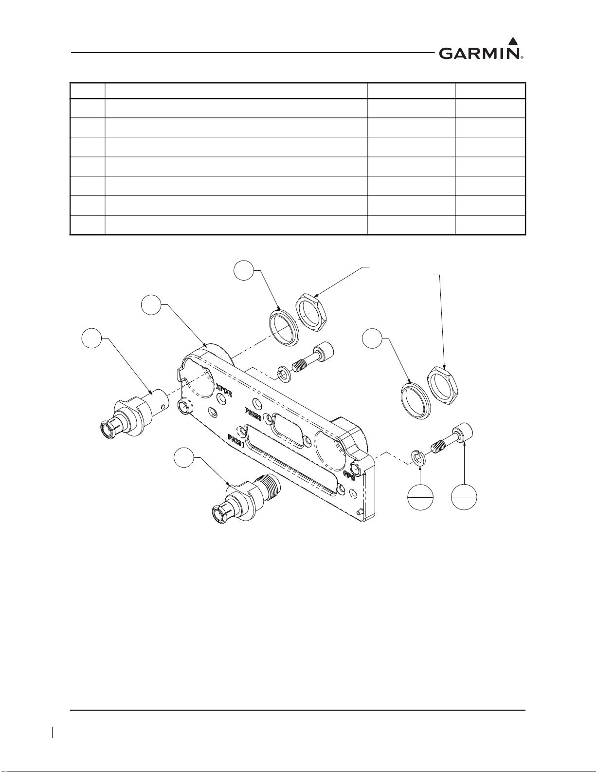
Table 6-4 Vertical Mount Backplate (P/N 011-02976-11)
2
1
3
4
NUTS SUPPLIED
WITH ITEMS 2 & 4
Item Description P/N Qty
DCP, connector plate, remote, GTX 3X5, w/secondaries
1
Connector, male/female special, BNC
2
Washer, shoulder, GNC 400
3
Connector, male/female, special, BNC/TNC
4
Washer, centering, no float
5
Washer, split lock, size 8
6
Screw, captive, 8-32, 0.62", 3/32 hex drv
7
125-00343-10 1
330-00053-01 1
212-00022-00 2
330-00053-02 1
212-00022-10 1
212-00018-04 2
211-00290-00 2
Figure 6-5 GTX 3X5 Vertical Mount with GPS, Backplate Assembly
(P/N 011-02976-11)
190-00734-21 GTX 3X5 Part 27 AML Maintenance Manual
Rev. 2 Page 6-6
Page 69

Table 6-5 Vertical Mount Backplate (P/N 011-02976-12)
1
NUT SUPPLIED
WITH ITEM 4
Item Description P/N Qty
DCP, connector plate, remote, GTX 3X5, w/secondaries
1
Connector, male/female, special, BNC/TNC
2
Washer, centering, no float
3
Washer, split lock, size 8
4
Screw, captive, 8-32, 0.62", 3/32 hex drv
5
125-00343-10 1
330-00053-02 1
212-00022-10 1
212-00018-04 2
211-00290-00 2
Figure 6-6 GTX 3X5 Vertical Mount with TNC XPDR Backplate Assembly
(P/N 011-02976-12)
190-00734-21 GTX 3X5 Part 27 AML Maintenance Manual
Rev. 2 Page 6-7
Page 70

6.1.1 GTX 335/345 Panel-Mounted Units
CAUTION
Ensure that the rotorcraft power is off before removal or re-installation of the GTX 3X5.
Unplug any auxiliary power supply.
This section contains procedures and requirements for removal and re-installation of the GTX 335/345
panel-mounted units installed under STC SR02124SE. After removal and re-installation, the GTX 335/345
return to service procedures must be performed in accordance with Section 9.
Removal
1. Insert the hex drive tool into the access hole on the unit face and rotate counterclockwise until the
unit is forced out about 3/8 inches.
2. Pull the unit straight out of the rack.
Re-Installation
CAUTION
Be sure not to overtighten the unit into the rack. Torque exceeding 8 in-lbf can damage the
locking mechanism.
NOTE
It may be necessary to insert the hex drive tool into the access hole and rotate the cam
mechanism 90 ° counterclockwise to ensure correct position prior to placing the unit in
the rack.
1. Slide the GTX 3X5 straight in the rack until it stops about 1 inch short of the final position.
2. Insert a 3/32” hex drive tool into the access hole at the bottom of the unit face.
3. Turn the hex tool clockwise while pressing on the left side of the bezel until the unit is firmly
seated in the rack.
4. Count the number of complete revolutions the hex screw can be turned, not exceeding 8 in-lbf of
torque. Be careful not to overtighten. Three turns is the minimum for proper installation. If fewer
than three turns are possible, ensure nothing obstructs the unit from fully seating in the rack.
5. Complete the applicable return to service procedures in Section 9.
190-00734-21 GTX 3X5 Part 27 AML Maintenance Manual
Rev. 2 Page 6-8
Page 71

For a complete list of GTX 3X5 transponder components, refer to Table 6-6. For detailed assembly
drawings, refer to Figure 6-7, Figure 6-8, and Figure 6-9.
Table 6-6 GTX 3X5 Transponder Parts List
Item Description P/N
GTX 335 Standard Kit
GTX 335 NV Standard Kit
1
GTX 335 GPS, Standard Kit
GTX 345, Standard Kit
GTX 345 GPS, Standard Kit
GTX 335 Remote, Standard Kit
GTX 335 Remote GPS, Standard Kit
2
GTX 345 Remote, Standard Kit
GTX 345 Remote GPS, Standard Kit
GTX 335 Remote, Vertical Mount, Standard Kit
GTX 335 Remote GPS, Vertical Mount, Standard Kit
3
GTX 345 Remote, Vertical Mount, Standard Kit
GTX 345 Remote GPS, Vertical Mount, Standard Kit
Screw, machine, flat, countersunk head 100 degrees, cross-recessed,
4
0.1380-32UNC-2A
010-01214-01
010-01214-21
010-01214-41
010-01216-01
010-01216-41
010-0215-01
010-0215-41
010-0217-01
010-0217-41
010-0215-02
010-0215-42
010-0217-02
010-0217-42
MS24693-S26
OR
OR
OR
Nut, self-locking, plate, one lug, reduced rivet spacing, low height,
5
steel, 0.138-32 UNC-3B
Rivet, solid, countersunk 100 degrees, precision head, 3/32 in. OD,
6
3/16 in. long
Nut, self-locking plate, two-lug, reduced rivet spacing, low height, steel,
7
0.138-32 UNC-3B
Screw, machine, flat, countersunk head, 100 degrees, cross-recessed,
8
0.1900-32 UNF-2A, 0.625 in. long
Insert, screw thread, molded-in, blind threaded, self-locking, floating,
9
sandwich panel, 0.190-32 UNJF-3B
10 GAE 12 Altitude Encoder, Standard Kit
11 Adapter, straight, 1/8 in. pipe to 1/4 in. hose
MS21071-06
MS20426AD3-3
MS21069L3
MS24693-S273
NAS1835A-3
011-03080-00
AN840-4D
190-00734-21 GTX 3X5 Part 27 AML Maintenance Manual
Rev. 2 Page 6-9
Page 72

Figure 6-7 Panel-Mounted GTX 3X5 Transponder
190-00734-21 GTX 3X5 Part 27 AML Maintenance Manual
Rev. 2 Page 6-10
Page 73

6.1.2 GTX 3X5R with Horizontal Install Rack
CAUTION
Ensure that the rotorcraft power is off before removal or re-installation of the GTX 3X5R.
Unplug any auxiliary power supply.
This section contains procedures and requirements for removal and installation of GTX 335R/345R
equipment installed using a standard remote mount. After removal and re-installation, the
GTX 335R/345R return to service procedures must be performed in accordance with Section 9.
Removal
1. Gain access to the transponder.
2. Insert the hex drive tool into the access hole on the unit face and rotate counterclockwise until the
unit is forced out about 3/8 inches.
3. Grab the pull-tab on the front of the unit and pull the unit straight out of the rack.
Re-Installation
CAUTION
Be sure not to overtighten the unit into the rack. Torque exceeding 8 in-lbf can damage the
locking mechanism.
NOTE
It may be necessary to insert the hex drive tool into the access hole and rotate the cam
mechanism 90° counterclockwise to ensure correct position prior to placing the unit in the
rack.
1. Visually inspect the connectors and pins to ensure they are not bent or damaged. Repair any
damage.
2. Slide the GTX 3X5 straight into the rack until it stops about 1 inch short of the final position.
3. Insert a 3/32” hex drive tool into the access hole at the bottom of the unit.
4. Turn the hex tool clockwise while pressing on the left side of the unit until the unit is firmly seated
in the rack.
5. Count the number of complete revolutions the hex screw can be turned, not exceeding 8 in-lbf of
torque. Be careful not to overtighten. Three turns is the minimum for proper installation. If fewer
than three turns are possible, ensure nothing obstructs the unit from fully seating in the rack.
6. Complete the applicable return to service procedures in Section 9.
190-00734-21 GTX 3X5 Part 27 AML Maintenance Manual
Rev. 2 Page 6-11
Page 74

Figure 6-8 GTX 3X5R Remote Transponder with Horizontal Mount
190-00734-21 GTX 3X5 Part 27 AML Maintenance Manual
Rev. 2 Page 6-12
Page 75

6.1.3 GTX 3X5R with Vertical Install Rack
CAUTION
Ensure the rotorcraft power is off before removal or re-installation of the GTX 3X5R.
Unplug any auxiliary power supply.
This section contains procedures for removal and installation of the GTX 335R/345R equipment installed
using a vertical mount. After removal and re-installation, the GTX 335R/345R return to service procedures
must be performed.
Removal
1. Access the transponder.
2. Remove the two captive screws securing the backplate to the transponder body using a 3/32" hex
tool.
3. Carefully remove the backplate and connector assembly from the unit.
4. While pulling, turn the large knob at the base of the unit counterclockwise until it can be pulled off
the tab on the base plate.
5. Tilt the unit so that the toe of the GTX 3X5 shoe fully disengages the base plate.
Installation
1. Tilt the unit so that the toe of the GTX 3X5 shoe fully engages the base plate.
2. Ensure that the unit is fully engaged and in line with the base.
3. Lift the large knob on the install rack up and over the tab on the base plate.
4. Turn the large knob clockwise until the unit is secure.
5. Carefully install the backplate onto the unit.
6. Secure with the two captive screws using a 3/32" hex tool.
7. Complete the applicable return to service procedures in Section 9.
190-00734-21 GTX 3X5 Part 27 AML Maintenance Manual
Rev. 2 Page 6-13
Page 76

Figure 6-9 GTX 3X5R Remote Transponder with Vertical Mount
190-00734-21 GTX 3X5 Part 27 AML Maintenance Manual
Rev. 2 Page 6-14
Page 77

6.1.4 Garmin Altitude Encoder
CAUTION
Ensure that the rotorcraft power is off before removal or re-installation of the
GTX 3X5/3X5R. Unplug any auxiliary power supply.
This section contains procedures and requirements for removal and installation of the Garmin Altitude
Encoder equipment installed under STC SR02124SE. After removal and re-installation, the
GTX 3X5/3X5R return to service procedures must be performed in accordance with Section 9.
Removal
1. Remove the transponder. Refer to Section 6.1 for details.
2. Remove the static line attached to the altitude encoder.
3. Disconnect wiring harness at the altitude encoder.
4. Remove the two screws securing the unit to the backplate.
Installation
1. Secure the altitude encoder to backplate assembly with two screws; torque to 8 in-lbf.
2. Connect wiring harness to altitude encoder.
3. Secure the static line to the altitude encoder using standard practices.
4. Install transponder. Refer to Section 6.1 for details.
5. Complete the applicable return to service procedures in Section 9.
6. Complete the static system and transponder checks described in Section 8.4.2.
190-00734-21 GTX 3X5 Part 27 AML Maintenance Manual
Rev. 2 Page 6-15
Page 78

Table 6-7 Garmin Altitude Encoder Kit (P/N 011-03080-00)
1
2
Item Description P/N Qty
1 Sub-assembly, altitude encoder, unit only
2 Screw, 4-40 X 0.250, PHP, SS/P, w/nyl
011-03080-01 1
211-60234-08 2
Figure 6-10 Garmin Altitude Encoder with Backplate Assembly
190-00734-21 GTX 3X5 Part 27 AML Maintenance Manual
Rev. 2 Page 6-16
Page 79

6.2 Transponder Antenna
The transponder antenna(s) is not installed by this STC. Refer to the antenna manufacturer's maintenance
information for removal and re-installation instructions.
6.3 Traffic Annunciator (If Installed)
CAUTION
Ensure that the rotorcraft power is off before removal or re-installation of the
GTX 3X5/3X5R. Unplug any auxiliary power supply.
This section contains procedures and requirements for removal and installation of the Vivisun Traffic
annunciator installed under STC SR02124SE. After removal and installation, the Traffic annunciator return
to service procedures must be performed in accordance with Section 9.
Removal
1. Disconnect all annunciator wiring.
2. Remove the annunciator indicator cap by applying pressure on the two sides of the switch cap and
pulling the switch cap from the switch body.
3. Gently remove the cap pins from the hinged slide retainer.
4. From the front of the indicator, locate the two slotted head integral mounting screws. Loosen the
two screws and remove the locking sleeve from the back of the indicator.
5. Pull the indicator out through the front of the mounting panel.
Installation
1. Insert the indicator body through the front of the mounting panel.
2. Slide the locking sleeve onto the indicator body until it touches the mounting panel.
3. From the front of the switch body, locate the two slot head integral mounting screws in the base of
the body. Tighten the two screws until the mounting sleeve is pulled against the panel. Torque 18
to 25 inch-ounces.
4. Reconnect all annunciator wiring.
5. Push in transponder circuit breaker.
190-00734-21 GTX 3X5 Part 27 AML Maintenance Manual
Rev. 2 Page 6-17
Page 80

Table 6-8 Traffic Annunciator Installation
1
2
3
Item Description P/N Qty
1 Annunciator, Traffic, Vivisun
2 Plug, Quick Connect, Vivisun
3 Mounting Sleeve (Part of Annunciator)
LED-40-17-HAI-E1G30 1
18-200 1
Figure 6-11 Traffic Annunciator Installation
190-00734-21 GTX 3X5 Part 27 AML Maintenance Manual
Rev. 2 Page 6-18
Page 81

7 SOFTWARE
7.1 Software Check.................................................................................................................................7-2
7.1.1 GTX 3X5 Software Version Check ...........................................................................................7-2
7.1.2 GTX 3X5R Software Version Check (GTN 6XX/7XX) ...........................................................7-3
7.2 GTX 3X5/3X5R Software Update....................................................................................................7-4
190-00734-21 GTX 3X5 Part 27 AML Maintenance Manual
Rev. 2 Page 7-1
Page 82

7.1 Software Check
NOTE
It is essential that the software version is correct. If the software version and/or part
number does not match those specified, or if the software is not successfully loaded,
DO NOT continue. Troubleshoot and resolve the issue before continuing.
NOTE
Screen shots in this section are provided for reference only. For approved GTX software
versions, refer to GTX 3X5 ADS-B AML STC Equipment List.
If software is loaded during maintenance, conduct a final software review.
7.1.1 GTX 3X5 Software Version Check
1. Start the GTX 3X5 in Normal mode.
2. Observe the start-up screen until you see “PRESS ENT FOR PRODUCT DATA.” Refer to
Figure 7-1 for details.
Figure 7-1 GTX 3X5 Start-Up Screen
3. Press the ENT key to navigate to the software version screen.
4. Verify the version number matches the approved version listed on the STC Equipment List. Refer
to Figure 7-2 for details.
Figure 7-2 GTX 3X5 Product Data Page
190-00734-21 GTX 3X5 Part 27 AML Maintenance Manual
Rev. 2 Page 7-2
Page 83

7.1.2 GTX 3X5R Software Version Check (GTN 6XX/7XX)
NOTE
The following procedures provide an overview to verify the software version of the
GTX 3X5R when interfaced with the GTN 6XX/7XX.
1. On the GTN 6XX/7XX System page, touch the External LRUs key.
2. Observe the reported GTX software version number. Refer to Figure 7-3 for details.
3. Verify the version number matches the approved version listed on the STC Equipment List.
Figure 7-3 GTN 6XX/7XX System Page
190-00734-21 GTX 3X5 Part 27 AML Maintenance Manual
Rev. 2 Page 7-3
Page 84

7.2 GTX 3X5/3X5R Software Update
CAUTION
If the unit is removed from the rotorcraft and operated, connect the transponder antenna
connection to a 50 Ω 5 watt load. The GTX transmits Mode S acquisition squitter pulses
once per second whether interrogations are received or not. Failure to connect a dummy
load or antenna during this procedure will cause the transponder to fail and possibly
damage the unit.
If a unit is replaced and does not have the approved version of software installed, software can be
downloaded from the Dealer Resource Center
below must be carried out on each GTX.
Software may be loaded by performing the following steps on the GTX Install Tool Software Upload page.
Refer to Figure 7-5.
1. Download the GTX 3X5/3X5R software from the Garmin Dealer Resource Center
2. Under “Step 1 - Select a File,” select the Browse key. Locate the Boot Block software file
containing the previously downloaded GTX 3X5/3X5R software.
3. Under “Step 2 - Upload Options,” select the options to be updated.
4. Under “Step 3 - Start Upload,” select the Upload key.
5. Wait for the upload to complete. Individual files will be marked as complete as they are installed.
6. Under “Step 1 - Select a File,” select the Browse key. Locate the Main System software file
containing the previously downloaded GTX 3X5/3X5R software.
7. Under “Step 2 - Upload Options,” select the “In File” versions to be updated.
8. Under “Step 3 - Start Upload,” select the Upload key.
9. Wait for the upload to complete. Individual files will be marked as complete as they are installed.
10. After successful completion, verify that the correct software versions and part numbers display on
the Transponder page of the Product Data group.
a. To view the Product Data group, it may be necessary to exit the Software Upload page and
select Configure Transponder. Refer to Figure 7-4.
. For dual GTX installations, the software loading procedures
.
Figure 7-4 Install Tool Dialog Box
190-00734-21 GTX 3X5 Part 27 AML Maintenance Manual
Rev. 2 Page 7-4
Page 85

Figure 7-5 GTX 3X5 Install Tool Software Upload Page
190-00734-21 GTX 3X5 Part 27 AML Maintenance Manual
Rev. 2 Page 7-5
Page 86

8 SYSTEM CONFIGURATION AND CHECKOUT
8.1 Overview...........................................................................................................................................8-2
8.2 System Checkout ..............................................................................................................................8-2
8.3 Configuration....................................................................................................................................8-2
8.3.1 GTX 3X5 Configuration ............................................................................................................8-2
8.3.2 GTX 3X5R Configuration (GTN 6XX/7XX)............................................................................8-2
8.4 GTX Test ..........................................................................................................................................8-3
8.4.1 Airborne Mode ...........................................................................................................................8-3
8.4.2 Regulatory Test ..........................................................................................................................8-4
8.4.3 ADS-B Out Test.........................................................................................................................8-4
8.4.4 Traffic Annunciator Test (If Installed).......................................................................................8-5
190-00734-21 GTX 3X5 Part 27 AML Maintenance Manual
Rev. 2 Page 8-1
Page 87

8.1 Overview
NOTE
EMI Testing is required as part of the post-installation checkout. It is not required as part
of regular maintenance.
This section contains instructions for configuring the GTX, as well as checks to ensure the system is
properly installed and functioning correctly. The steps that are not applicable to a particular installation
may be skipped.
8.2 System Checkout
Original GTX is Re-Installed
If the original GTX is being re-installed, configuration and software loading are not required. Continue to
the GTX Test described in Section 8.4.
New, Repaired, or Exchanged GTX is Installed
If a new, repaired, or exchanged GTX is installed, AML approved software (refer to Section 7.1 and
Section 7.2) must be loaded to the unit.
8.3 Configuration
NOTE
Ensure the Post-Installation Checkout Log remains with the rotorcraft permanent records
upon completion of any maintenance activities.
Retrieve the Post-Installation Checkout Log from the rotorcraft permanent records. For the maintenance
activities that repaired or replaced the previous GTX, verify the configuration of the GTX as defined by the
data contained in the Post-Installation Checkout Log.
8.3.1 GTX 3X5 Configuration
Hold down the ENT key and press the ON key to access the configuration pages. The FUNC key
sequences forward through the configuration pages. The CLR key reverses through the pages. The 8 or 9
key scrolls up or down through the items on each configuration page. The CRSR key highlights selectable
fields on each page. When a field is highlighted, the 0 – 9 keys enter numeric data and the 8 or 9 keys move
through list selections. Press the ENT key to accept changes. When a field is highlighted, pressing the
FUNC key moves to the next configuration page without saving the changes.
Changes made through the configuration pages are stored internally in the GTX 3X5 unit and in the
configuration module located in the rack connector backshell. To exit the configuration pages, turn the
power off. Then turn on again (without holding the ENT key) for normal operation.
8.3.2 GTX 3X5R Configuration (GTN 6XX/7XX)
For GTX 3X5R installations interfacing to a GTN 6XX/7XX, configuration of the GTX is accomplished
through the GTX Installation Tool. Within the GTX Installation Tool, an Offline mode is available under
the GTX menu that allows configuration as if a unit is connected. This allows for the saving, loading, and
generating summaries of configuration. Refer to Section 7.2 for instructions on downloading, installing,
and connecting the installation tool to the GTX 3X5/3X5R unit.
190-00734-21 GTX 3X5 Part 27 AML Maintenance Manual
Rev. 2 Page 8-2
Page 88

8.4 GTX Test
NOTE
For dual transponder installations, the procedures contained in this section must be
completed for each installed transponder.
Operation of the GTX 3X5 is accomplished using the faceplate of the unit. Refer to Section 3.1for details.
The GTX 3X5R is controlled using the GTN 6XX/7XX. Refer to Section 3.2 for details. Refer to the
operational documents listed in Table 1-1 for basic GTX operation.
8.4.1 Airborne Mode
The transponder must be placed in an airborne state to reply to any Mode A or Mode C interrogations. The
GTX uses advanced Air/Ground logic to determine the state of the transponder. This logic must be
temporarily defeated in order to place the transponder in an airborne state for testing. To place the
transponder into an airborne state, perform the following applicable procedure.
Panel-Mounted Transponder
1. Start the GTX in Ground Test mode (hold the CRSR key and press the ON key).
2. “GROUND TEST MODE” alert message will be displayed on the GTX 3X5 message screen.
Remote-Mounted Transponder (GTN Interface)
NOTE
A GTX or GTN in Ground Test mode or Airborne Test mode will automatically return to
normal operation of the Air/Ground logic when the unit is powered off and then turned on
in Normal mode. When the unit is in Ground Test or Airborne Test mode, an alert message
will be annunciated on the GTX or GTN screen.
1. Start the GTN in Configuration mode (hold the HOME key while cycling power).
2. Navigate to the XPDR 1 Installation Settings page.
a. Select External Systems.
b. Select XPDR.
3. Press the Force Airborne Test key.
4. Restart the GTN in Normal mode.
Remote-Mounted Transponder (GTX 3X5R Only)
NOTE
Airborne Test mode is for testing purposes only. Once testing is complete, either return the
collective switch to original settings or remove the GTX from Ground Test mode.
1. Connect the GTX 3X5 installation tool to GTX 3X5R unit.
2. Place unit into Ground Test mode located on the State page.
190-00734-21 GTX 3X5 Part 27 AML Maintenance Manual
Rev. 2 Page 8-3
Page 89

8.4.2 Regulatory Test
With the transponder operating in Normal mode and in an Airborne or Ground Test state (refer to
Section 8.4.1), the following regulatory tests are required to be performed every 24 calendar months, or
any time the transponder is removed, replaced, or modified.
1. Altitude reporting equipment tests in accordance with 14 CFR Part 91.411 and Part 43
Appendix E.
2. ATC transponder tests and inspections in accordance with 14 CFR Part 91.413 and Part 43
Appendix F.
These regulatory tests require the use of a Mode S transponder ramp tester, such as an Aeroflex IFR-6000
or TIC TR-220. Specific instructions for operating the ramp tester are contained in the applicable
operator's manual.
8.4.3 ADS-B Out Test
NOTE
Software version 5.30 or later is required on the TR-220.
The following ADS-B Out parameters must be verified in accordance with Title 14 of the Code of Federal
Regulations (14 CFR) § 91.227 any time the position source (GPS) is replaced/modified. The test is
performed using a transponder ramp test set, such as the Aeroflex IFR-6000 or TIC TR-220. For
instructions on operating the ramp tester, refer to the manufacturer’s documentation.
1. Ensure the rotorcraft is in a location where a GPS signal can be received (i.e., outdoors with a clear
view of the sky).
2. Power on the rotorcraft/avionics and ensure that the GTX is powered on.
3. If the GTX is configured for pilot control of the ADS-B transmitter, ensure ADS-B TX is selected
ON.
4. Temporarily put the GTX into Airborne mode. Refer to Section 8.4.1.
5. If dual GPS sources are connected to the GTX, each GPS source must be checked separately by
disabling the GPS source not being checked. Disable the GPS source not being checked by
covering the GPS antenna or removing power from that navigator. Verify that the GPS source not
being checked is no longer receiving satellite data.
6. Ensure the GPS source being checked has acquired a position.
7. Select ALT mode on the GTX.
8. Using the transponder test set, verify the following ADS-B Out parameters are being transmitted:
NACv ≥ 1
SDA ≥ 2
SIL ≥ 3
NACp ≥ 8
NIC ≥ 7
9. If dual GPS sources are connected to the GTX, repeat steps 5 through 8 for the other GPS source.
190-00734-21 GTX 3X5 Part 27 AML Maintenance Manual
Rev. 2 Page 8-4
Page 90

10. Revert the GTX to its previous configuration as follows:
a. If a connected air/ground switch was defeated in step 4, then place the connected switch back
to the on-ground position.
b. If the GTX squat switch configuration settings were changed in step 4, revert the GTX settings
back to the previous configuration.
11. Select STBY mode on the GTX.
If no other service is to be performed, continue to the return to service checks in Section 9.1.
8.4.4 Traffic Annunciator Test (If Installed)
To test the annunciator, press the Traffic Test key on the GTX 3X5 Install Tool State page, and verify that
the “Traffic” annunciator illuminates.
190-00734-21 GTX 3X5 Part 27 AML Maintenance Manual
Rev. 2 Page 8-5
Page 91

9 SYSTEM RETURN TO SERVICE
After removing and re-installing or replacing the GTX 3X5, perform the system checkout procedures in
Section 8.2.
9.1 Maintenance Records
After performing the required return to service procedures, a record of maintenance should be provided to
the owner/operator in accordance with 14 CFR 43.9 and 14 CFR 91.417.
The following should be provided in the maintenance record entry:
Part number and version number of any software updates performed during maintenance
Part number and serial number of any LRU that was replaced
Any other applicable information related to the maintenance work performed on the rotorcraft
190-00734-21 GTX 3X5 Part 27 AML Maintenance Manual
Rev. 2 Page 9-1
Page 92

APPENDIX A INSTALLATION-SPECIFIC INFORMATION
A.1 Rotorcraft-Specific Information .........................................................................................................A-2
A.2 Equipment Interfaced to the GTX ......................................................................................................A-4
A.3 GTX 3X5 Airframe-Specific Installation .........................................................................................A-11
A.3.1 Airbus Helicopters AS-350, AS-350B, AS-350B2, AS-350B3, AS-350BA, and AS-350D A-12
A.3.2 Airbus Helicopters EC-120B .................................................................................................A-13
A.3.3 Airbus Helicopters EC-130T2 and EC-130B4 ......................................................................A-14
A.3.4 Airbus Helicopters EC-135, EC-135P1, EC-135P2, EC-135P2+, EC-135P3, EC-135T1, EC-
135T2, and EC-135T2+, EC-135T3 ......................................................................................A-15
A.3.5 Agusta A109, A109A, A109A II, A109C, A109K2, A109E, A109S, AW109SP, A119,
and AW119 MKII ..................................................................................................................A-16
A.3.6 Bell 206A and 206B...............................................................................................................A-17
A.3.7 Bell 206L, 206L-1, 206L-3, and 206L-4 ...............................................................................A-18
A.3.8 Bell 407..................................................................................................................................A-19
A.3.9 Bell 427 and 429 ....................................................................................................................A-20
A.3.10 Enstrom Helicopters 480, 480B, F-28, F-28A, F-28C, 280, 280C, 280F, and 280FX..........A-21
A.3.11 MD Helicopters 369, 369D, 369E, 369F, 369FF, and 500N................................................. A-22
A.3.12 MD Helicopter 600N .............................................................................................................A-23
A.3.13 Robinson R22, R22 Alpha, R22 Beta, and R22 Mariner....................................................... A-24
A.3.14 Robinson R44 and R44 II ......................................................................................................A-25
A.3.15 Robinson R66.........................................................................................................................A-26
A.3.16 Sikorsky 269, 269C, 269C-1, and 269D................................................................................ A-27
A.4 GTX 3X5 Configuration Log ...........................................................................................................A-28
A.5 GTX 335/335R Configuration Log...................................................................................................A-29
A.6 GTX 345/345R Configuration Log...................................................................................................A-30
190-00734-21 GTX 3X5 Part 27 AML Maintenance Manual
Rev. 2 Page A-1
Page 93

A.1 Rotorcraft-Specific Information
GENE
5272CRAFT SPECIFIC INFORMATION
RAL INFORMATION
'DWH %\
5272CRAFT
5272&5$)70$.(
5272&5$)702'(/
5272&5$)76(5,$/
5272&5$)75(*
+(;$''5(66
0RG/HYHO
6HULDO
GTX #2 [N/A]
0RG/HYHO
6HULDO
GTX #1
8QLW31
8QLW0RGHO
8QLW31
8QLW0RGHO
Figure A-1 Rotorcraft-Specific Information
Sheet 1 of 2
190-00734-21 GTX 3X5 Part 27 AML Maintenance Manual
Rev. 2 Page A-2
Page 94

ELECTRICAL LOAD ANALYSIS
ITEMS REMOVED FROM 5272CRAFT
ELECTRICAL LOAD (A) [1]
COMMENT
Subtotal:
ITEMS ADDED TO 5272CRAFT
ELECTRICAL LOAD (A) [1]
COMMENT
Subtotal
Net Change in Bus Load:
[1] Use typical current draw when performing this calculation.
190-00734-21 GTX 3X5 Part 27 AML Maintenance Manual
Rev. 2 Page A-3
Figure A-1 Rotorcraft-Specific Information
Sheet 2 of 2
Page 95

A.2 Equipment Interfaced to the GTX
NOTE
This information is optional and is not required to be completed or maintained with the
rotorcraft records.
Document the equipment that is interfaced to the GTX. Use the following guidance when filling out the
information. When applicable, check that the correct LRU is used for the interface or write in the GTX port
number or numbers used for the interface. This is generally applicable only to serial ports, such as
RS-232 and ARINC 429.
190-00734-21 GTX 3X5 Part 27 AML Maintenance Manual
Rev. 2 Page A-4
Page 96

GTX #1 INTERFACED EQUIPMENT
Manufacturer/Model
GPS
Source
Remote
Control
&
Traffic/
Weather
Altitude
Source
Heading
Source
Radar
Altitude
Source
Traffic
(TAS/TCAS)
Audio
Panel
Data
Forwarding
Garmin
GTX 3X5( )
Garmin
GTN 6XX/7XX
Garmin
GNS 400W/500W
Garmin
G500H (GDU 620)
Garmin
GDL 69A (SXM)
Garmin
GDC 74( )
Garmin
GAE
ACK Tech
A-30
Icarus Instruments
3000
Sandia
SAE 5-35
Shadin
8800T
Shadin
F/ADC-200
Shadin
F/ADC-2000
Shadin
ADC 200+
Trans-Cal Industries
IA-RS232-X
Trans-Cal Industries
SSD120
90004-003
(Bendix King)
(Bendix King)
1000-PFD
ADS-B In
External
B & D
Honeywell
KDC 281
Honeywell
KDC 481
Aspen
Display
Display
Source
Figure A-2 Interfaced Equipment Table
Sheet 1 of 6
190-00734-21 GTX 3X5 Part 27 AML Maintenance Manual
Rev. 2 Page A-5
Page 97

Manufacturer/Model
GPS
Source
Remote
Control
&
Traffic/
Weather
Altitude
Source
Heading
Source
Radar
Altitude
Source
Traffic
(TAS/TCAS)
Audio
Panel
Data
Forwarding
1000H-PFD
EXP 5000
AHS-85E
EFS 40/50 (SG465)
SN 3308
SN 3500
GRS 77( )
GAD 42( )
RA-4500
KRA 405B
GRA 55/5500
TAS 6XX (9900BX)
Skywatch SKY497
Skywatch SKY899
(Bendix King)
KTA 870/810
(Bendix King)
KTA 970/910
GTS 8XX
GTS Processor
SL 10(___)
SL 15(___)
GMA 35( )
ADS-B In
External
Aspen
Avidyne
Collins
Bendix King
Sandel
Sandel
Garmin
Garmin
Free Flight
Honeywell
Garmin
Avidyne (Ryan)
L3
L3
Honeywell
KMH 880/820
Honeywell
Display
Display
Source
KMH 980/920
Garmin
(800/820/850)
Garmin
(825/855)
Garmin
Garmin
Garmin
Figure A-2 Interfaced Equipment Table
Sheet 2 of 6
190-00734-21 GTX 3X5 Part 27 AML Maintenance Manual
Rev. 2 Page A-6
Page 98

Manufacturer/Model
GPS
Source
Remote
Control
&
Traffic/
Weather
Altitude
Source
Heading
Source
Radar
Altitude
Source
Traffic
(TAS/TCAS)
Audio
Panel
Data
Forwarding
GMA 340 / 347
GMA 350
GMA 1347
(Bendix King)
(Bendix King)
King)
(Bendix King)
PMA 6000
PMA 7000
PMA 8000
A710 / A711
DVCS 6100
AMS 42 / AMS 44
AMS 50
ADS-B In
External
Garmin
Garmin
Garmin
Honeywell
KMA 24
Honeywell
KMA 24H-70/71
Honeywell (Bendix
KMA 26
Honeywell
KMA 28
PS Engineering
PS Engineering
PS Engineering
Techinsonics
Becker
NAT
NAT
Display
Display
Source
Figure A-2 Interfaced Equipment Table
Sheet 3 of 6
190-00734-21 GTX 3X5 Part 27 AML Maintenance Manual
Rev. 2 Page A-7
Page 99

GTX #2 INTERFACED EQUIPMENT
Manufacturer/Model
GPS
Source
Remote
Control
&
Traffic/
Weather
Altitude
Source
Heading
Source
Radar
Altitude
Source
Traffic
(TAS/TCAS)
Audio
Panel
Data
Forwarding
Garmin
GTX 3X5()
Garmin
GTN 6XX/7XX
Garmin
GNS 400W/500W
Garmin
G500H (GDU 620)
Garmin
GDL 69A (SXM)
Garmin
GDC 74()
Garmin
GAE
ACK Tech
A-30
Icarus Instruments
3000
Sandia
SAE 5-35
Shadin
8800T
Shadin
F/ADC-200
Shadin
F/ADC-2000
Shadin
ADC 200+
Trans-Cal Industries
IA-RS232-X
Trans-Cal Industries
SSD120
90004-003
(Bendix King)
(Bendix King)
1000-PFD
ADS-B In
External
B & D
Honeywell
KDC 281
Honeywell
KDC 481
Aspen
Display
Display
Source
Figure A-2 Interfaced Equipment Table
Sheet 4 of 6
190-00734-21 GTX 3X5 Part 27 AML Maintenance Manual
Rev. 2 Page A-8
Page 100

Manufacturer/Model
GPS
Source
Remote
Control
&
Traffic/
Weather
Altitude
Source
Heading
Source
Radar
Altitude
Source
Traffic
(TAS/TCAS)
Audio
Panel
Data
Forwarding
1000H-PFD
EXP 5000
AHS-85E
EFS 40/50 (SG465)
SN 3308
SN 3500
GRS 77()
GAD 42()
RA-4500
KRA 405B
GRA 55/5500
TAS 6XX (9900BX)
Skywatch SKY497
Skywatch SKY899
(Bendix King)
KTA 870/810
(Bendix King)
KTA 970/910
GTS 8XX
GTS Processor
SL 10(___)
SL 15(___)
GMA 35( )
ADS-B In
External
Aspen
Avidyne
Collins
Bendix King
Sandel
Sandel
Garmin
Garmin
Free Flight
Honeywell
Garmin
Avidyne (Ryan)
L3
L3
Honeywell
KMH 880/820
Honeywell
Display
Display
Source
KMH 980/920
Garmin
(800/820/850)
Garmin
(825/855)
Garmin
Garmin
Garmin
Figure A-2 Interfaced Equipment Table
Sheet 5 of 6
190-00734-21 GTX 3X5 Part 27 AML Maintenance Manual
Rev. 2 Page A-9
 Loading...