

Page 1
GTX 33X and GTX 3X5 ADS-B
Maintenance Manual
Contains Instructions for Continued Airworthiness for
STC SA01714WI
Aircraft make, model, registration number, and serial
number and accompanying STC configuration
information in Appendix A must be completed and saved
with aircraft permanent records.
190-00734-11 September 2019 Revision 7
Page 2

© 2013-2019 Garmin International or its subsidiaries
All Rights Reserved
Except as expressly provided herein, no part of this manual may be reproduced, copied, transmitted,
disseminated, downloaded or stored in any storage medium, for any purpose without the express prior
written consent of Garmin. Garmin hereby grants permission to download a single copy of this manual and
of any revision to this manual onto a hard drive or other electronic storage medium to be viewed and to
print one copy of this manual or of any revision hereto, provided that such electronic or printed copy of this
manual or revision must contain the complete text of this copyright notice and provided further that any
unauthorized commercial distribution of this manual or any revision hereto is strictly prohibited.
Garmin
®
is a registered trademark of Garmin International or its subsidiaries. GDU™ and GTN™ are
trademarks of Garmin International or its subsidiaries. These trademarks may not be used without the
express permission of Garmin.
®
Adobe
is a registered trademark of Adobe Systems Incorporated. All rights reserved.
The Bluetooth word mark and logos are registered trademarks owned by Bluetooth SIG, Inc. and any use
of such marks by Garmin is under license. Other trademarks and trade names are those of their respective
owners.
At Garmin, we value your opinion.
For comments about this guide, please e-mail Techpubs.Salem@garmin.com
For comments about Garmin aviation products, email Avionics@garmin.com
Garmin International, Inc.
1200 E. 151st Street
Olathe, KS 66062 USA
Telephone: (913) 397-8200
www.garmin.com
Garmin (Europe) Ltd.
Liberty House, Bulls Copse Road
Hounsdown Business Park
Southampton, SO40 9LR, UK
Phone: +44 (0) 23 8052 4000
Fax: +44 (0) 23 8052 4004
Garmin AT, Inc.
2345 Turner Rd., SE
Salem, OR 97302 USA
Telephone: (503) 581-8101
.
190-00734-11 GTX 33X and GTX 3X5 ADS-B Maintenance Manual
Rev. 7 Page i
Page 3
Revision
5 10/05/16
6 12/08/17
Revision
Date
RECORD OF REVISIONS
Description
Updated the standard rack part number.
Moved GPS keep alive input requirement to optional interface.
Updated main and ADS-B software to v2.05
Updated GTX 33/330 software to v8.04
Updated GTX 3X5 main software to v2.12 and ADSB software to v2.10
Added models to bonding table B-1
7
09/09/19
Added Diversity unit part numbers and descriptions.
CURRENT REVISION DESCRIPTION
Section Description
1.6.1 Updated to add Diversity units to section.
2 Added Diversity units to list of GTX 3X5 models.
Updated to add Diversity units to section.
2.3
2.4
2.5
2.6 Added GTX 335D and GTX 345D to Table 2-1 GTX Electrical Load.
3 Updated to add Diversity units to section.
3.2 Updated to add Diversity units to section.
3.3 Updated to add Diversity units to section.
Updated Figure 2-3 to include GTX 335D and GTX 335DR units.
Updated to add Diversity units to section.
Updated Figure 2-4 to include GTX 345D and GTX 345DR units.
Updated to add Diversity units to section.
Updated Figure 2-5 to include GTX 335DR and GTX 345DR units.
3.4 Updated to add Diversity units to section.
4.5 Updated to add Diversity units to section.
4.6 Updated to add Diversity units to section.
5.4.2 Added GTX 345D and GTX 345DR to include the J3252 connector.
Added “ADS-B OUT FUNCTION FAIL”, “STANDBY ALERT”, “TRANSPONDER
ACTIVE”, and “DIVERSITY FAIL” pins to Table 5-9 GTX 3X5/3X5R Discrete Outputs.
Changed “AUDIO INHIBIT #1” pin to “AUDIO MUTE” in Table 5-11 GTX 3X5/3X5R
Discrete Inputs.
5.4.4
Changed “AUDIO INHIBIT #2” pin to “AUDIO CANCEL” in Table 5-11 GTX 3X5/3X5R
Discrete Inputs.
Added “TRAFFIC AUDIO MUTE” and “TRAFFIC AUDIO CANCEL” pins in Table 5-11
GTX 3X5/3X5R Discrete Inputs.
190-00734-11 GTX 33X and GTX 3X5 ADS-B Maintenance Manual
Rev. 7 Page ii
Page 4
Section Description
Added Table 6-4 and Figure 6-9 GTX 3X5D with Backplate Assembly (P/N 011-04340-
6.3
6.3.1 Updated to add Diversity units to section.
6.3.2 Updated to add Diversity units to section.
6.3.3 Updated to add Diversity units to section.
8.4.1 Updated to add Diversity units to section.
8.4.2 Updated to add Diversity units to section.
8.5.2 Updated to add Diversity units to section.
8.6 Corrected “Part 23” to “Part 43”.
8.8 Updated to add Diversity units to section.
02).
Added Table 6-5 and Figure 6-10 GTX 3X5DR with Backplate Assembly (P/N 01104340-10).
Appendix A
Updated to add Diversity units to section. Added Diversity sections to Post-Installation
Configuration Log.
190-00734-11 GTX 33X and GTX 3X5 ADS-B Maintenance Manual
Rev. 7 Page iii
Page 5
INFORMATION SUBJECT TO EXPORT CONTROL LAWS
WARNING
WARNING
CAUTION
WARNING
CAUTION
NOTE
This document may contain information that is subject to the Export Administration Regulations (EAR)
issued by the United States Department of Commerce (15 CFR, Chapter VII, Subchapter C) and may not
be exported, released, or disclosed to foreign nationals inside or outside of the United States without first
obtaining an export license. A violation of the EAR may be subject to a penalty of up to 10 years
imprisonment and a fine of up to $1,000,000 under Section 2410 of the Export Administration Act of 1979.
Include this notice with any reproduced portion of this document.
This information in this document is subject to change without notice. Visit Garmin’s Dealer Resource
Center for current updates and supplemental information concerning the operation of Garmin products.
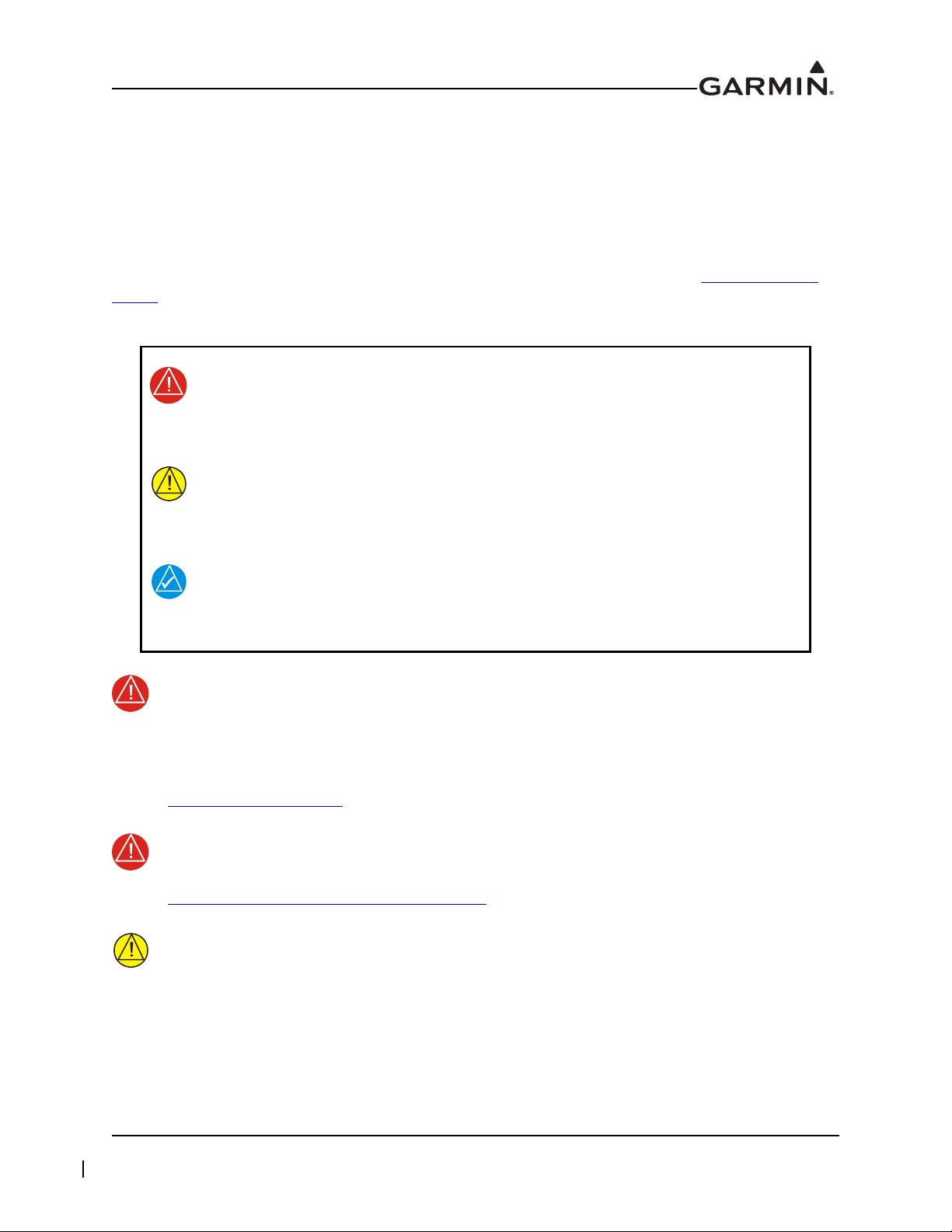
DEFINITIONS OF WARNINGS, CAUTIONS, AND NOTES
Warnings indicate that immediate attention must be given to avoid potential
equipment damage and personal injury should the instructions be disregarded.
Cautions indicate an alert to potential damage to the equipment if the
procedural step is not directly followed.
Notes indicate additional information is needed.
This product, its packaging, and its components contain chemicals known to the State of
California to cause cancer, birth defects, or reproductive harm. This notice is being
provided in accordance with California's Proposition 65. If you have any questions or
would like additional information, please refer to our website at
www.garmin.com/prop65.
Perchlorate Material - special handling may apply. Refer to
www.dtsc.ca.gov./hazardouswaste/perchlorate.
The GTX 330/330D and GTX 335/345 units have a special anti-reflective coated display
that is sensitive to waxes and abrasive cleaners. CLEANERS CONTAINING AMMONIA
WILL HARM THE ANTI-REFLECTIVE COATING. It is important to clean the display
using a clean, lint-free cloth, with a cleaner that is safe for anti-reflective coatings.
190-00734-11 GTX 33X and GTX 3X5 ADS-B Maintenance Manual
Rev. 7 Page iv
Page 6

TABLE OF CONTENTS
1 INTRODUCTION..............................................................................................................................1-1
1.1 Content, Scope, Purpose.............................................................................................................1-2
1.2 Organization ...............................................................................................................................1-2
1.3 Applicability...............................................................................................................................1-3
1.4 Publications ................................................................................................................................1-3
1.5 Revision and Distribution...........................................................................................................1-3
1.6 Reference....................................................................................................................................1-4
2 SYSTEM DESCRIPTION.................................................................................................................2-1
2.1 GTX 330/330D...........................................................................................................................2-2
2.2 GTX 33/33D...............................................................................................................................2-4
2.3 GTX 335/335D/335R/335DR ....................................................................................................2-6
2.4 GTX 345/345D/345R/345DR ....................................................................................................2-8
2.5 GTX 335R/335DR/345R/345DR with Legacy G1000 ............................................................2-10
2.6 Electrical Load Information .....................................................................................................2-11
3 GTX CONTROL AND OPERATION.............................................................................................3-1
3.1 GTX 330/330D...........................................................................................................................3-2
3.2 GTX 335/335D/345/345D..........................................................................................................3-4
3.3 GTX 33/33D and GTX 335R/335DR/345R/345DR..................................................................3-7
3.4 GTX 335R/335DR/345R/345DR with Legacy G1000 ..............................................................3-8
3.5 GTX 3X5 Install Tool ..............................................................................................................3-10
4 INSTRUCTIONS FOR CONTINUED AIRWORTHINESS.........................................................4-1
4.1 Applicability...............................................................................................................................4-2
4.2 Airworthiness Limitations..........................................................................................................4-2
4.3 Servicing Information ................................................................................................................4-3
4.4 Maintenance Intervals ................................................................................................................4-4
4.5 Visual Inspection........................................................................................................................4-5
4.6 Electrical Bonding Test..............................................................................................................4-7
4.7 Additional Instructions...............................................................................................................4-7
5 TROUBLESHOOTING ....................................................................................................................5-1
5.1 GTX General Troubleshooting...................................................................................................5-2
5.2 GTX Failure Annunciations .......................................................................................................5-4
5.3 GTX 33X Connector Pinout Information.................................................................................5-11
5.4 GTX 3X5 Connector Pinout Information.................................................................................5-15
6 UNIT REMOVAL AND RE-INSTALLATION..............................................................................6-1
6.1 GTX 330/330D...........................................................................................................................6-2
6.2 GTX 33/33D...............................................................................................................................6-4
6.3 GTX 3X5....................................................................................................................................6-5
6.4 Transponder Antenna ...............................................................................................................6-19
7 SOFTWARE.......................................................................................................................................7-1
7.1 Software Check ..........................................................................................................................7-2
7.2 GTX 33/330 Software Update....................................................................................................7-5
7.3 GTX 3X5 Software Update........................................................................................................7-7
8 SYSTEM CONFIGURATION AND CHECKOUT .......................................................................8-1
8.1 Overview ....................................................................................................................................8-2
8.2 System Checkout........................................................................................................................8-2
8.3 GTX 33/330 Configuration ........................................................................................................8-3
8.4 GTX 3X5 Configuration ............................................................................................................8-4
8.5 GTX Airborne Test Mode ..........................................................................................................8-5
190-00734-11 GTX 33X and GTX 3X5 ADS-B Maintenance Manual
Rev. 7 Page v
Page 7

8.6 Regulatory Test ..........................................................................................................................8-7
8.7 ADS-B Out Test .........................................................................................................................8-8
8.8 GTX 3X5 with TCAS System Test (GX000 Only) ...................................................................8-9
9 SYSTEM RETURN TO SERVICE PROCEDURE........................................................................9-1
9.1 Maintenance Records .................................................................................................................9-1
APPENDIX A INSTALLATION SPECIFIC INFORMATION ........................................................A-1
APPENDIX B SPECIAL BONDING PROCEDURES.......................................................................B-1
B.1 Considerations for Untreated or Bare Dissimilar Metals ..........................................................B-2
B.2 Preparation of Aluminum Surfaces ........................................................................................... B-5
B.3 Composite Aircraft.................................................................................................................... B-6
B.4 Tube-and-Fabric Aircraft ........................................................................................................ B-10
B.5 Bonding Jumper ...................................................................................................................... B-12
190-00734-11 GTX 33X and GTX 3X5 ADS-B Maintenance Manual
Rev. 7 Page vi
Page 8

LIST OF FIGURES
Figure 2-1 GTX 330 or GTX 330D Interface Summary ........................................................................2-3
Figure 2-2 GTX 33 or GTX 33D Interface Summary ............................................................................2-5
Figure 2-3 GTX 335/335D/335R/335DR Interface Summary ...............................................................2-7
Figure 2-4 GTX 345/345D/345R/345DR Interface Summary ...............................................................2-9
Figure 2-5 GTX 335R/335DR/345R/345DR Interface Summary with Legacy G1000 .......................2-10
Figure 3-1 GTX 330/330D Front Panel ..................................................................................................3-2
Figure 3-2 GTX 335/335D/345/345D Front Panel ................................................................................3-4
Figure 3-3 GTN 7XX Transponder Control ...........................................................................................3-7
Figure 3-4 GTN 6XX Transponder Control ...........................................................................................3-7
Figure 3-5 GNS 480 Transponder Control .............................................................................................3-7
Figure 3-6 G1000 Transponder Control .................................................................................................3-9
Figure 3-7 G1000 Transponder Control .................................................................................................3-9
Figure 3-8 USB A and USB B Connectors ..........................................................................................3-10
Figure 3-9 GTX 3X5 State Page ..........................................................................................................3-11
Figure 3-10 GTX 3X5 Status Page .........................................................................................................3-12
Figure 3-11 GTX 3X5 Configuration Group ..........................................................................................3-13
Figure 3-12 GTX 3X5 Diagnostics Group .............................................................................................3-14
Figure 3-13 GTX 3X5 Product Data Group ...........................................................................................3-15
Figure 5-1 GTX (All Models) Transponder Troubleshooting ................................................................5-3
Figure 5-2 GTX 330/330D Transponder Failure/Fault Messages ..........................................................5-4
Figure 5-3 GTX 33/33D Transponder Failure/Fault Messages ..............................................................5-5
Figure 5-4 GTX 3X5 Transponder Alerts ..............................................................................................5-6
Figure 5-5 Rear View, Connector P3301 .............................................................................................5-11
Figure 5-6 GTX 33/330 ARINC 429 Connections ...............................................................................5-14
Figure 5-7 Rear View, Connector J3251 ..............................................................................................5-15
Figure 5-8 Rear View, Connector J3252 ..............................................................................................5-17
Figure 6-1 GTX 330 Mounting Rack/Connector Assembly ..................................................................6-3
Figure 6-2 GTX 33 Mounting Rack/Connector Assembly ....................................................................6-4
Figure 6-3 GTX 3X5 Connector Kits .....................................................................................................6-5
Figure 6-4 GTX 3X5 without GPS Back Plate Assembly (P/N 011-02976-00) ....................................6-6
Figure 6-5 GTX 3X5 with GPS Back Plate Assembly (P/N 011-02976-01) .........................................6-6
Figure 6-6 GTX 3X5 Vertical Mount without GPS, Back Plate Assem
Figure 6-7 GTX 3X5 Vertical Mount with GPS, Back Plate Assembly (P/N 011-02976-11) ..............6-8
Figure 6-8 GTX 3X5 Vertical Mount with TNC XPDR Back Plate Assembly (P/N 011-02976-12) ...6-8
Figure 6-9 GTX 3X5D with Backplate Assembly (P/N 011-04340-02) ................................................6-9
Figure 6-10 GTX 3X5DR with Backplate Assembly (P/N 011-04340-10) ...........................................6-10
Figure 6-11 GTX 3X5 Mounting Rack/Connector Assembly ...............................................................6-12
Figure 6-12 GTX 3X5R Standard Mounting Rack/Connector Assembly ..............................................6-14
Figure 6-13 GTX 3X5R G1000 Mounting Rack/Connector Assembly .................................................6-14
Figure 6-14 GTX 3X5R Vertical Mounting Rack/Connector Assembly ...............................................6-16
Figure 6-15 Garmin Altitude Encoder with Back Plate Assembly ........................................................6-18
Figure 7-1 GTX 330 Start-Up Screen ....................................................................................................7-2
Figure 7-2 GTX 330 Product Data Page ................................................................................................7-2
Figure 7-3 GTX 3X5 Start-Up Screen ....................................................................................................7-3
Figure 7-4 GTX 3X5 Product Data Page ...............................................................................................7-3
Figure 7-5 GTN 6XX/7XX System Page ...............................................................................................7-3
Figure 7-6 GX000 System Status Page ..................................................................................................7-4
Figure 7-7 Software Update Connection ................................................................................................7-5
bly (P/N 011-02976-10) .........6-7
190-00734-11 GTX 33X and GTX 3X5 ADS-B Maintenance Manual
Rev. 7 Page vii
Page 9

Figure 7-8 GTX 3X5 Install Tool Software Upload Page ......................................................................7-8
Figure B-1 Electrical Bonding Preparation – Nut Plate .........................................................................B-2
Figure B-2 Electrical Bonding Preparation – Bolt/Nut Joint .................................................................B-2
Figure B-3 Electrical Bond Preparation – Terminal Lug .......................................................................B-2
Figure B-4 Fiberglass Insulation for Carbon Material ...........................................................................B-6
Figure B-5 Aluminum Tape Joint ..........................................................................................................B-7
Figure B-6 Aluminum Tape Ground Termination ................................................................................. B-8
Figure B-7 Remote GTX Aluminum Tape Installation ......................................................................... B-9
Figure B-8 Electrical Bonding Using Conductive Clamp .................................................................... B-11
Figure B-9 Bonding Strap .................................................................................................................... B-13
190-00734-11 GTX 33X and GTX 3X5 ADS-B Maintenance Manual
Rev. 7 Page viii
Page 10

LIST OF TABLES
Table 1-1 Reference Documentation ....................................................................................................1-3
Table 2-1 GTX Electrical Load ...........................................................................................................2-11
Table 4-1 Maintenance Intervals ...........................................................................................................4-4
Table 5-1 GTX 33X Pinout .................................................................................................................5-11
Table 5-2 GTX 33X Encoded Altitude Pin Assignments ...................................................................5-13
Table 5-3 GTX 33/330 Discrete Outputs ............................................................................................5-13
Table 5-4 GTX 33/330 Discrete Inputs ...............................................................................................5-14
Table 5-5 GTX 33/330 RS-232 Connections ......................................................................................5-14
Table 5-6 J3251 Pinout .......................................................................................................................5-15
Table 5-7 J3252 Pinout .......................................................................................................................5-17
Table 5-8 GTX 3X5/3X5R Encoded Altitude Pin Assignments ........................................................5-18
Table 5-9 GTX 3X5/3X5R Discrete Outputs ......................................................................................5-19
Table 5-10 GTX 3X5/3X5R Configurable Output Pins .......................................................................5-19
Table 5-11 GTX 3X5/3X5R Discrete Inputs ........................................................................................5-20
Table 5-12 GTX 3X5/3X5R Configurable Input Pins ..........................................................................5-20
Table 5-13 GTX 3X5/3X5R RS-232 Connections ...............................................................................5-21
Table 5-14 GTX 3X5/3X5R ARINC 429 Connections ........................................................................5-21
Table 5-15 GTX 345/345R RS-422 Connections .................................................................................5-21
Table 5-16 GTX 345/345R HSDB Connections ...................................................................................5-22
Table 6-1 GTX 3X5 Connector Kit Hardware ......................................................................................6-5
Table 6-2 Standard/G1000 Mount Back Plate Hardware .....................................................................6-5
Table 6-3 Vertical Mount Back Plate Hardware ...................................................................................6-7
Table 6-4 Standard and G1000 Mount Backplate Hardware ................................................................6-9
Table 6-5 Vertical Mount Backplate Hardware ..................................................................................6-10
Table 6-6 Garmin Altitude Encoder Kit - P/N 011-03080-00 ............................................................6-18
Table 8-1 Ramp Test Pressure Altitude Check Scenario ......................................................................8-9
Table B-1 Ground Plane Definitions and Ground Path Resistance Requirements ...............................B-3
Table B-2 Composite Airframe Bonding Hardware .............................................................................B-7
Table B-3 Tube and Fabric Airframe Bonding Hardware ..................................................................B-10
Table B-4 Airframe Bonding Hardware .............................................................................................B-13
190-00734-11 GTX 33X and GTX 3X5 ADS-B Maintenance Manual
Rev. 7 Page ix
Page 11

1 INTRODUCTION
1.1 Content, Scope, Purpose ...................................................................................................................1-2
1.2 Organization......................................................................................................................................1-2
1.3 Applicability .....................................................................................................................................1-3
1.4 Publications.......................................................................................................................................1-3
1.5 Revision and Distribution .................................................................................................................1-3
1.6 Reference ..........................................................................................................................................1-4
1.6.1 Terminology ...............................................................................................................................1-4
1.6.2 Acronyms ...................................................................................................................................1-4
190-00734-11 GTX 33X and GTX 3X5 ADS-B Maintenance Manual
Rev. 7 Page 1-1
Page 12

1.1 Content, Scope, Purpose
This document provides Instructions for Continued Airworthiness (ICA) of the GTX 33X and GTX 3X5
with ADS-B functionality installed and compliant to ADS-B Out version 2, under AML STC SA01714WI.
This document satisfies the requirements for continued airworthiness as defined by 14 CFR Part 23.1529
and Appendix G. Information in this document is required to maintain the continued airworthiness of the
GTX 33X and GTX 3X5.
1.2 Organization
The following outline briefly describes the organization of this manual.
Section 2: System Overview
Provides a description of the GTX 33X and GTX 3X5 equipment installed by this STC.
Section 3: Control and Operation
Provides basic control and operation information specifically tailored to maintenance practices.
Section 4: Instructions for Continued Airworthiness
Provides instructions for continued airworthiness of the GTX 33X and GTX 3X5 ADS-B units.
Section 5: Troubleshooting
Provides troubleshooting information to aid in diagnosing and resolving problems with GTX 33X and
GTX 3X5 system equipment.
Section 6: Unit Removal and Reinstallation
Provides instructions for the removal and replacement of GTX 33X and GTX 3X5 ADS-B units.
Section 7: Software
Provides instructions for loading software on GTX 33X and GTX 3X5 ADS-B units.
Section 8: System Configuration and Checkout
Provides instructions for configuring and testing of GTX 33X and GTX 3X5 system equipment.
Section 9: System Return to Service Procedure
Specifies return-to-service procedures to be performed upon completion of maintenance to GTX 33X and
GTX 3X5 system equipment.
Appendix A: Aircraft Specific Information
Provides a template to record aircraft specific installation and configuration data for GTX 33X and
GTX 3X5 system equipment.
Appendix B: Special Bonding Procedures
Provides instructions for achieving an electrical bond with GTX 33X and GTX 3X5 system equipment.
190-00734-11 GTX 33X and GTX 3X5 ADS-B Maintenance Manual
Rev. 7 Page 1-2
Page 13
1.3 Applicability
This document applies to all aircraft with either the GTX 33X or the GTX 3X5 installed in accordance with
STC SA01714WI. Modification of an aircraft by this Supplemental Type Certificate (STC) obligates the
aircraft operator to include the maintenance information provided by this document in the operator’s
Aircraft Maintenance Manual and the operator’s Aircraft Scheduled Maintenance Program.
1.4 Publications
In addition to this manual, the following documents are recommended to perform maintenance based on
the installed and interfaced equipment. It is the responsibility of the owner/operator to ensure the latest
applicable versions of these documents are used during operation, servicing, or maintenance of the
airplane.
Table 1-1 Reference Documentation
Document Garmin P/N
GTX 33X and GTX 3X5 ADS-B AML STC Equipment List
GTN 625/635/650 Pilot’s Guide
AFMS, GTX 33X and GTX 3X5 AML STC
GTN 725/750 Pilot’s Guide
GNS 400W Series Installation Manual
GNS 500W Series Installation Manual
GNS 480 (CNX80) Color GPS/NAV/COM Installation Manual
GNS 480 Pilot’s Guide
G1000 System Installation Manual
GTN 6XX/7XX Part 23 AML STC Installation Manual
GTX 3XX Part 23 AML STC Installation Manual
005-00734-05
190-01004-03
190-00734-15
190-01007-03
190-00356-08
190-00357-08
560-0982-01
190-00502-00
190-00303-00
190-01007-A3
190-00734-10
1.5 Revision and Distribution
This document is required for maintaining the continued airworthiness of the aircraft. Garmin Dealers may
obtain the latest revision of this document at the Garmin Dealer Resource Center
Dealers are notified of manual revision changes via a Garmin Service Bulletin.
Owner and operators may obtain the latest revision of this document at www.flyGarmin.com
contacting a Garmin dealer. Garmin contact information is available at www.flyGarmin.com
190-00734-11 GTX 33X and GTX 3X5 ADS-B Maintenance Manual
Rev. 7 Page 1-3
, website.
or by
.
Page 14

1.6 Reference
1.6.1 Terminology
Except where specifically noted, references made to “GTX 33X” or “GTX 3X5” will apply to the
GTX 330/330D/33/33D or GTX 335/335D/335R/335DR/345/345D/345R/345DR, respectively.
ADS-B or ADS-B Out refers to version 2 ADS-B Out only.
ADS-B In refers to TIS-B traffic and FIS-B weather received from ground stations over UAT as well as
ADS-B and ADS-R traffic targets received directly over 1090 MHz or UAT.
Throughout this document references will be made to metallic aircraft. For the purposes of this manual,
metallic aircraft will be those with an aluminum skin. Nonmetallic aircraft refers to all other aircraft
(e.g., wooden aircraft, aircraft with composite skin, or aircraft with tube and fabric construction).
Unless otherwise stated, all units of measure are US standard units.
The term squitter refers to a burst or broadcast of aircraft-tracking data that is transmitted periodically by a
Mode S transponder without interrogation from a controller’s radar.
1.6.2 Acronyms
AC: Advisory Circular ICA: Instructions for Continued Airworthiness
ADC: Air Data Computer ICAO: International Civil Aviation Organization
ADS-B: Automatic Dependent Surveillance -
Broadcast
AHRS: Attitude Heading Reference System MFD: Multifunction Display
AML: Approved Model List PED: Portable Electronic Device
ATC: Air Traffic Control SBAS: Satellite-Based Augmentation System
ATCRBS: Air Traffic Control Radar Beacon System SPI: Special Position Identifier
EGNOS: European Geostationary Navigation
Overlay Service
ES: Extended Squitter STC: Supplemental Type Certificate
FAA: Federal Aviation Administration TAS: Traffic Advisory System
FIS-B: Flight Information System-Broadcast TCAS: Traffic Alert and Collision Avoidance
GAE: Garmin Altitude Encoder TIS: Traffic Information Service
GNS: Garmin Navigation System TSO: Technical Standard Order
GNSS: Global Navigation Satellite System UAT: Universal Access Transceiver
GPS: Global Positioning System VSWR: Voltage Standing Wave Ratio
GTN: Garmin Touchscreen Navigator
GTX: Garmin Transponder
I/O: Input/Output
SRM: Structural Repair Manual
System
WAAS: Wide Area Augmentation System
190-00734-11 GTX 33X and GTX 3X5 ADS-B Maintenance Manual
Rev. 7 Page 1-4
Page 15

2 SYSTEM DESCRIPTION
2.1 GTX 330/330D .................................................................................................................................2-2
2.2 GTX 33/33D .....................................................................................................................................2-4
2.3 GTX 335/335D/335R/335DR...........................................................................................................2-6
2.4 GTX 345/345D/345R/345DR...........................................................................................................2-8
2.5 GTX 335R/335DR/345R/345DR with Legacy G1000...................................................................2-10
2.6 Electrical Load Information............................................................................................................2-11
Garmin GTX 33X and GTX 3X5 units operate on radar frequencies, receiving ground radar or TCAS
interrogations. The GTX transmits a coded response of pulses to ground-based radar on a frequency of
1090 MHz. Each unit has IDENT capability and replies to ATCRBS Mode A, Mode C and Mode S
All-Call interrogation. The GTX 345/345D/345R/345DR units include ADS-B In which provides TIS-B
and FIS-B data via UAT and 1090 MHz. The GTX 3X5 units offer an optional Garmin altitude encoder to
meet the required barometric pressure altitude source and an optional internal GPS/SBAS source to meet
the required GNSS position source integrity for ADS-B Out.
The Garmin transponders approved by this STC are in the family of GTX 33X and GTX 3X5 transponders.
The ES option of the GTX 33X units provides ADS-B extended squitter functionality.
The GTX 33X models include:
GTX 33
GTX 330
GTX 33D
GTX 330D
The GTX 3X5 units all provide ADS-B Out functionality. GTX 345/345R units provide ADS-B In. The
GTX 3X5 models include:
GTX 335
GTX 335D
GTX 345
GTX 345D
GTX 335R
GTX 335DR
GTX 345R
GTX 345DR
ADS-B technology improves situational awareness and flight safety. A Garmin transponder with ADS-B
capabilities will automatically transmit position, velocity, and heading information to other aircraft and
ground stations. The current air traffic control system depends on a transponder request for pertinent
aircraft information, whereas ADS-B provides automatic transmission of aircraft information without a
request.
190-00734-11 GTX 33X and GTX 3X5 ADS-B Maintenance Manual
Rev. 6 Page 2-1
Page 16

2.1 GTX 330/330D
GTX 330/330D units are stand alone, panel mounted units that operate through the integrated display.
GTX 330/330D units can be controlled by an external control unit such as the GTN 6XX/7XX or the
GNS 480. They can display TIS-A information on an approved display unit, via an RS-232 digital
interface.
GTX 330/330D units provide the following features.
Mode S transponder
ADS-B Out capability
Entry and display of squawk code and flight ID
Display of pressure altitude
Display of density altitude
Display of outside air temp
Display of flight timers
Audio output
TIS-A traffic output to a compatible display
The transponder annunciates when the unit has an ADS-B Out failure to alert the crew that the unit has a
degraded ADS-B system.
GTX 330/330D units communicate through the following interfaces.
ARINC 429
RS-232
Gray code
Discrete I/O
Power is provided by the aircraft’s existing avionics bus. Non-diversity GTX 330 units interface with a
transponder antenna mounted to the bottom of the fuselage. GTX 330D diversity units interface to a
transponder antenna mounted to the top of the fuselage as well as the antenna mounted to the bottom.
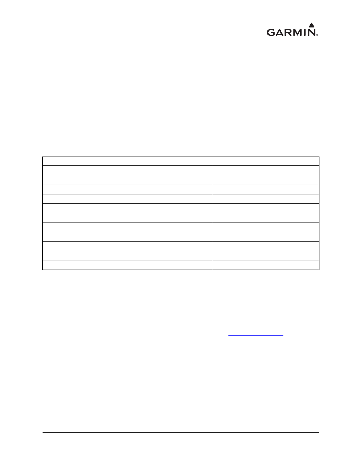
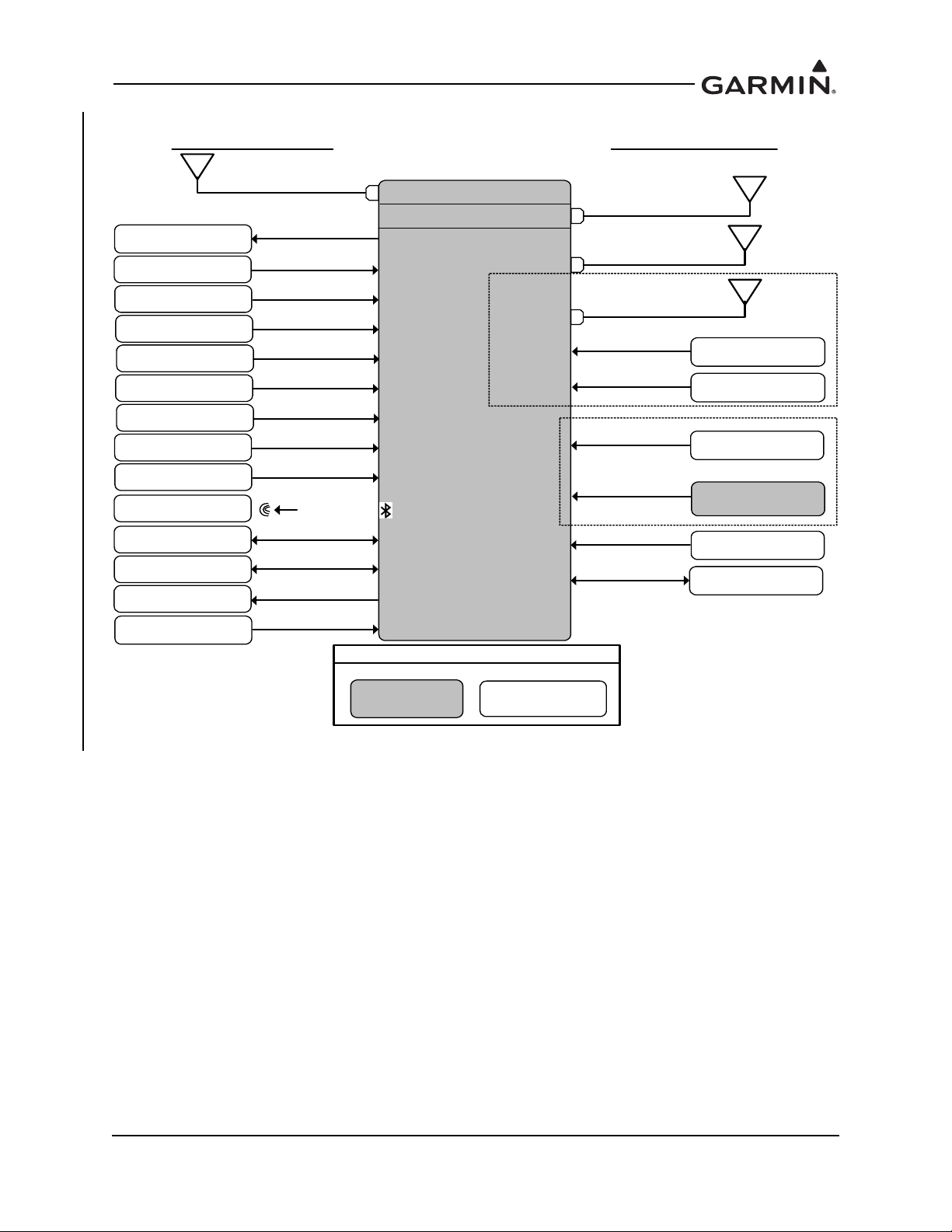
Figure 2-1 provides a summary of the interfaces provided for the GTX 330 or GTX 330D. Refer to
GTX 3XX Part 23 AML STC Installation Manual for interfaces allowed under this STC.
190-00734-11 GTX 33X and GTX 3X5 ADS-B Maintenance Manual
Rev. 6 Page 2-2
Page 17
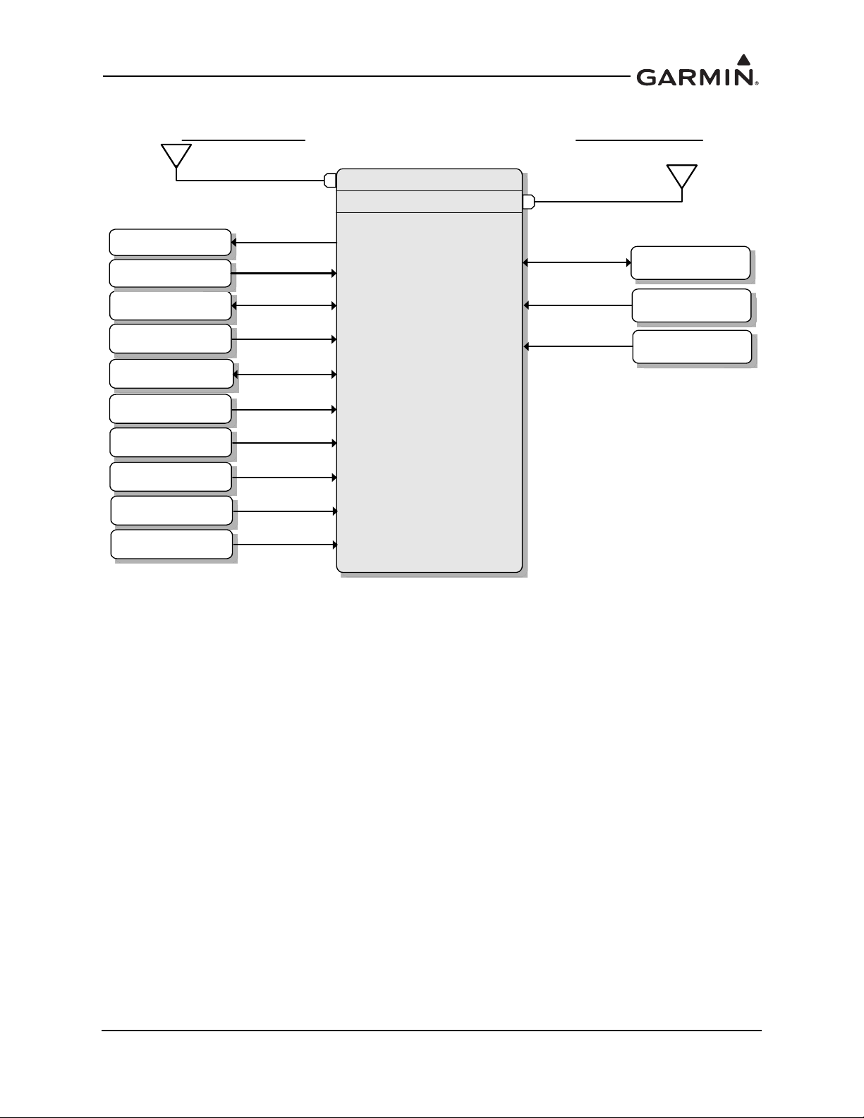
Figure 2-1 GTX 330 or GTX 330D Interface Summary
GTX 330
or
GTX 330D
Bottom Antenna
GTX 330D
Installs Only
Traffic System
Audio Panel
Optional Interfaces
Heading Source
Secondary GPS
Display
Required Interfaces
Altitude Source
Power/Ground
Top Antenna
GPS
Temperature
Squat Switch
External STBY
External Ident
Radar Altitude
190-00734-11 GTX 33X and GTX 3X5 ADS-B Maintenance Manual
Rev. 6 Page 2-3
Page 18

2.2 GTX 33/33D
GTX 33/33D units are remote mounted and require a display/control interface as provided by the
GTN 6XX/7XX or GNS 480 in order to be installed in accordance with this STC. Basic transponder
functions of the GTX 33/33D are identical to the GTX 330/330D.
GTX 33/33D units provide the following features.
Mode S transponder
ADS-B Out capability
Entry and display of squawk code and flight ID*
Display of pressure altitude*
Display of density altitude*
Display of outside air temp*
Display of flight timers*
Audio output
TIS-A traffic output to a compatible display
*Requires supported external control and display system
The transponder annunciates when the unit has an ADS-B Out failure to alert the crew that the unit has a
degraded ADS-B system.
GTX 33/33D units communicate through the following interfaces.
ARINC 429
RS-232
Gray code
Discrete I/O
Power is provided by the aircraft’s existing avionics bus. Non-diversity GTX 33 units interface with a
transponder antenna mounted to the bottom of the fuselage. GTX 33D units interface to a transponder
antenna mounted to the top of the fuselage as well as an antenna mounted to the bottom.
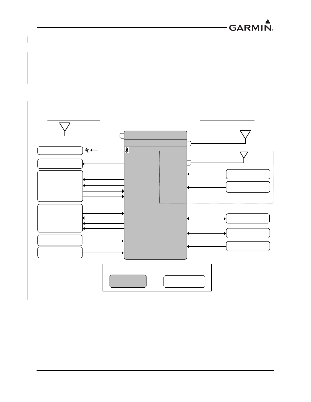
Figure 2-2 provides a summary of the interfaces provided for the GTX 33 or GTX 33D. Refer to
GTX 3XX Part 23 AML STC Installation Manual for interfaces allowed under this STC.
190-00734-11 GTX 33X and GTX 3X5 ADS-B Maintenance Manual
Rev. 6 Page 2-4
Page 19
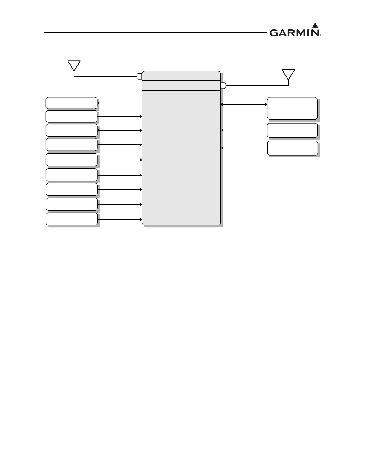
Figure 2-2 GTX 33 or GTX 33D Interface Summary
GTX 33
or
GTX 33D
Bottom Antenna
GTX 33D
Installs Only
Garmin
GTN 6XX/7XX
Or
GNS 480
Traffic System
Audio Panel
Optional Interfaces
Heading Source
Secondary GPS
Temperature
Squat Switch
Required Interfaces
Altitude Source
Power/Ground
Top Antenna
External Ident
External Standby
Radar Altitude
190-00734-11 GTX 33X and GTX 3X5 ADS-B Maintenance Manual
Rev. 6 Page 2-5
Page 20

2.3 GTX 335/335D/335R/335DR
The GTX 335/335D/335R/335DR units are panel or remote mounted units providing Mode S with ADS-B
Out extended squitter capability. The panel mounted unit contains an integrated display while the remote
mounted unit requires an interface to a control source for normal operation and functionality.
GTX 335/335D/335R/335DR units provide the following features:
Mode S transponder
ADS-B Out capability
Optional internal GNSS receiver
Optional altitude encoder module
Entry and display of squawk code and flight ID
Display of pressure altitude
Display of outside air temp
Display of density altitude
Display of flight timers
Audio output
TIS-A traffic output to a compatible display
The transponder annunciates when the unit has an ADS-B Out failure to alert the crew that the unit has a
degraded ADS-B system. GTX 335/335R units interface with a transponder antenna mounted to the
bottom of the fuselage. GTX 335D/335DR units interface to a transponder antenna mounted to the top of
the fuselage as well as an antenna mounted to the bottom.
GTX 335/335D/335R/335DR units communicate through the following interfaces:
ARINC 429
RS-232
Gray code
Discrete I/O
Figure 2-3 provides a summary of the interfaces provided for the GTX 335/335D/335R/335DR. Refer to
GTX 3XX Part 23 AML STC Installation Manual for interfaces allowed under this STC.
190-00734-11 GTX 33X and GTX 3X5 ADS-B Maintenance Manual
Rev. 6 Page 2-6
Page 21
GTX 335/335R/
335D/335DR
GPS Antenna
GPS Source
Audio Panel
GTX 3X5 with GPS only
GTX 335R/335DR
Control
Power/Ground
Altitude Source
Heading Source
Air Data Source
Secondary GPS
Radio Altitude
Source
Existing LRUNew LRU
Legend
Optional Interfaces
Required Interfaces
Squat Sw itch
Garmin Altitude
Encoder
OR
Temperature
External Ident
External Standby
Traffic System
For XPDR Cross-Talk
Keep Alive Input
Bottom Antenna
GTX 335D/335DR
Installs O nly
Top Antenna
Figure 2-3 GTX 335/335D/335R/335DR Interface Summary
190-00734-11 GTX 33X and GTX 3X5 ADS-B Maintenance Manual
Rev. 6 Page 2-7
Page 22

2.4 GTX 345/345D/345R/345DR
The GTX 345/345D/345R/345DR units are panel or remote mounted units providing Mode S with ADS-B
Out extended squitter, and UAT and 1090 receivers for ADS-B In capabilities. The panel mounted unit
contains an integrated display while the remote mounted units require an interface to a control source for
normal operation and functionality.
GTX 345/345D/345R/345DR units provide the following features:
Mode S transponder
ADS-B Out capability
ADS-B In capability with built-in 1090 MHz and UAT receivers
Optional internal GNSS receiver
Optional altitude encoder module
Entry and display of squawk code and flight ID
Display of pressure altitude
Display of outside air temp
Display of density altitude
Display of flight timers
Audio output
Bluetooth interface for display of weather and traffic on portable devices
The transponder annunciates when the unit has an ADS-B failure to alert the crew that the unit has a
degraded ADS-B In or ADS-B Out system. GTX 345/345R units interface with a transponder antenna
mounted to the bottom of the fuselage. GTX 345D/345DR units interface to a transponder antenna
mounted to the top of the fuselage as well as an antenna mounted to the bottom.
GTX 345/345D/345R/345DR units communicate through the following interfaces:
HSDB
ARINC 429
RS-232
RS-422
Gray code
Discrete I/O
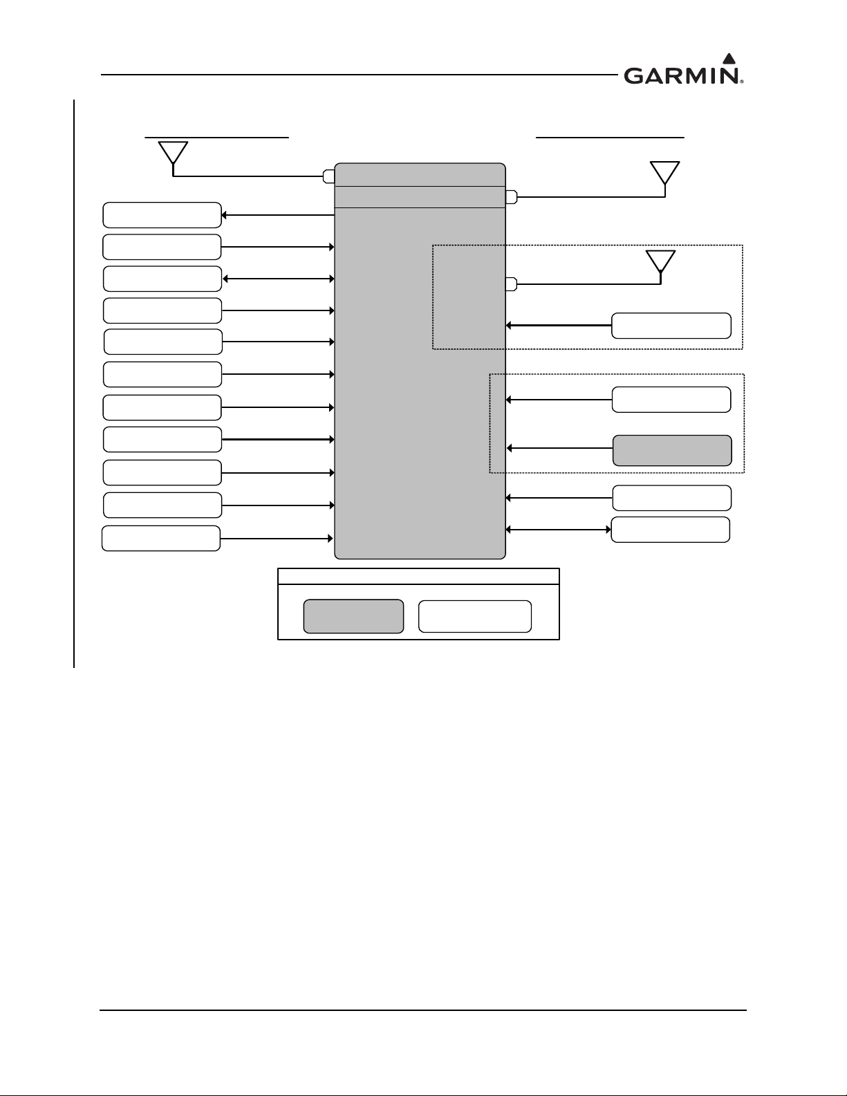
Figure 2-4 provides a summary of the interfaces provided for the GTX 345/345D/345R/345DR. Refer to
GTX 3XX Part 23 AML STC Installation Manual for interfaces allowed under this STC.
190-00734-11 GTX 33X and GTX 3X5 ADS-B Maintenance Manual
Rev. 6 Page 2-8
Page 23
TAS/TCAS I
Traffic Sensor
ADS-B Traffic
FIS-B Display
Bluetooth Device
GTX 345/345R/
345D/345DR
GPS Antenna
GPS Source
Audio Panel
Bottom Antenna
GTX 3X5 with GPS only
GTX 345R/345DR
Control
Power/Ground
Altitude Source
Heading Source
Air D ata S ource
Secondary GPS
Radio Altitude
Source
Existing LRUNew LRU
Legend
Optional Interfaces
Required Interfaces
Squat Switch
Bluetooth
External Traffic
Annunciator
For N o Display Install
Garmin Altitude
Encoder
OR
Temperature
External Ident
External Standby
Keep Alive Input
Bottom Antenna
GTX 345D/345DR
Installs O nly
Top Antenna
Time Mark
GTX 345D/345DR
only
Figure 2-4 GTX 345/345D/345R/345DR Interface Summary
190-00734-11 GTX 33X and GTX 3X5 ADS-B Maintenance Manual
Rev. 6 Page 2-9
Page 24
2.5 GTX 335R/335DR/345R/345DR with Legacy G1000
Bluetooth Device
GTX 335R/335DR/
345R/345DR
GPS Antenna
Audio Panel
GTX 3X5 with GPS only
Power/Ground
GIA #1
Existing LRU
New LRU
Legend
Optional Interfaces
Required Interfaces
Bluetooth
RS-232
RS-232
GIA #2
RS-232
RS-422
TRAFFIC
WEATHER
ARINC 429
TRUE HEADING
GIA #2
GIA 63W
GPS Source
GIA 63W software dependent,
refer to IM for compatible software
TAS/TCAS
AURAL MUTE
DISCRETE
ARINC 429
DISCRETE
ARINC 429
TRAFFIC
XPDR / HEADING
DISCRETE
STBY/OPR
SELF TEST
Landing Gear
Switch
DISCRETE
Keep Alive Input
Bottom Antenna
GTX 335DR/345DR
Installs Only
Top Antenna
Time Mark
GTX 345DR only
The Legacy G1000 configuration includes certain G1000 systems that can be updated with a G1000
interface card. The GTX 335R/335DR provides all the functions listed under the GTX 335/335D/335R/
335DR to include ADS-B Out. The GTX 345R provides all the functions listed under the GTX 345/345D/
345R/345DR with the exception that the ADS-B In traffic and weather will be displayed as an emulation of
the GDL 90 weather and traffic displays. The GTX 345R/345DR provides FIS-B weather (NEXRAD and
METARS) and TIS-B traffic within the confines of the GDL 90 interface. The GTX 345R/345DR provides
TIS-B traffic and FIS-B weather on PED via Bluetooth. Refer to GTX 3XX Part 23 AML STC Installation
Manual for additional information.
Figure 2-5 provides a basic summary of the GTX 335R/335DR/345R/345DR interface for the legacy
G1000 system.
190-00734-11 GTX 33X and GTX 3X5 ADS-B Maintenance Manual
Rev. 6 Page 2-10
Figure 2-5 GTX 335R/335DR/345R/345DR Interface Summary with Legacy G1000
Page 25
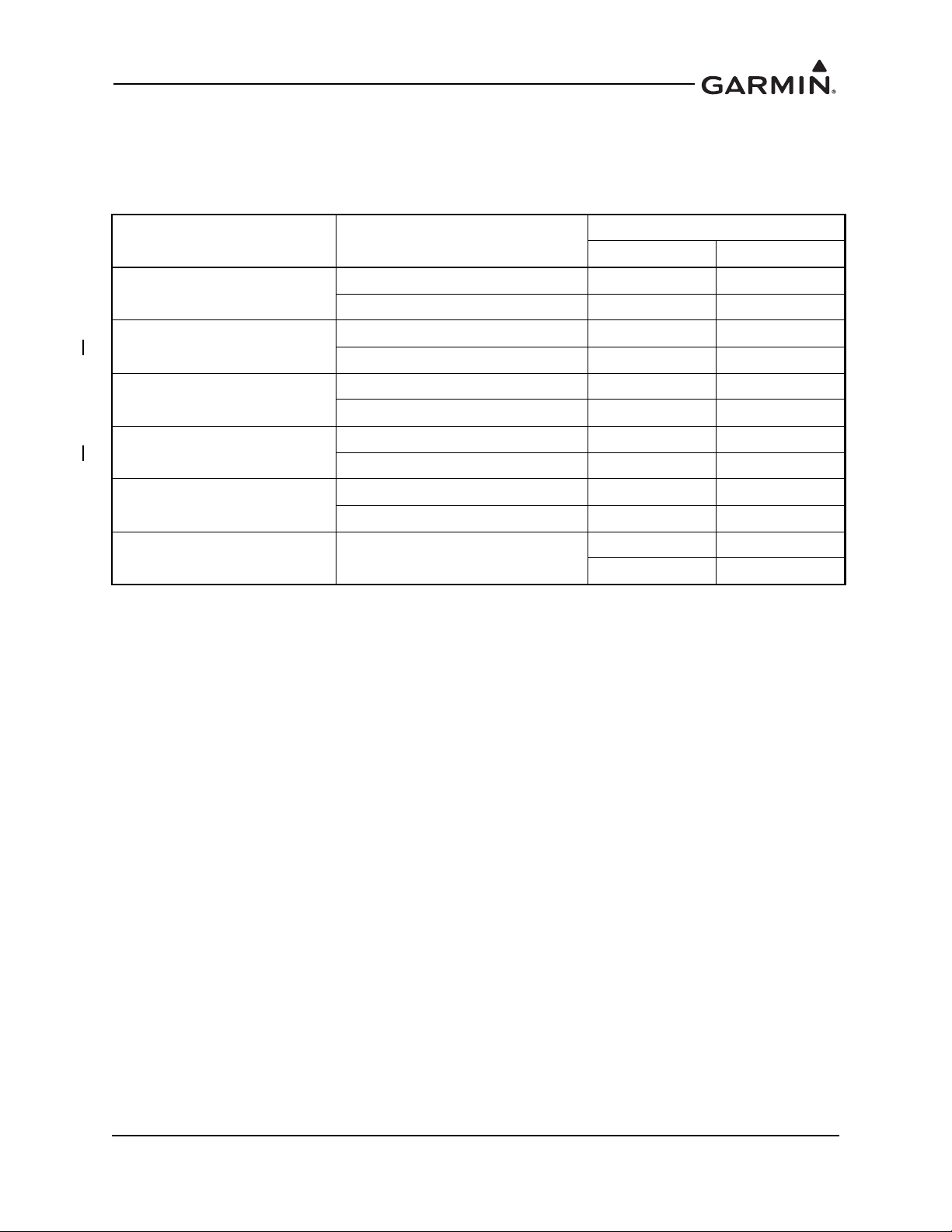
2.6 Electrical Load Information
Electrical load information for the GTX is provided below. Appendix A of this document contains details
specific to the load changes for the installation.
Table 2-1 GTX Electrical Load
Unit Characteristic
Maximum full TSO reply rate 3.1 A 1.6 A
GTX 33/330
Maximum quiescent 1.1 A 0.85 A
Input current, typical 0.57 A 0.29 A
GTX 335/335D
Input current, maximum 0.86 A 0.43 A
Specification
14 VDC 28 VDC
GTX 335, GPS
Input current, typical 0.72 A 0.36A
Input current, maximum 1.22 A 0.61 A
Input current, typical 0.72 A 0.36 A
GTX 345/345D
Input current, maximum 1.30 A 0.65 A
Input current, typical 1.07 A 0.54 A
GTX 345, GPS
Input current, maximum 1.43 A 0.72 A
GTX 335/345, GPS Input current, GPS KEEP ALIVE
65 µA typical 20 µA typical
85 µA maximum 40 µA maximum
190-00734-11 GTX 33X and GTX 3X5 ADS-B Maintenance Manual
Rev. 6 Page 2-11
Page 26
3 GTX CONTROL AND OPERATION
NOTE
3.1 GTX 330/330D .................................................................................................................................3-2
3.2 GTX 335/335D/345/345D ................................................................................................................3-4
3.3 GTX 33/33D and GTX 335R/335DR/345R/345DR ........................................................................3-7
3.4 GTX 335R/335DR/345R/345DR with Legacy G1000.....................................................................3-8
3.5 GTX 3X5 Install Tool.....................................................................................................................3-10
3.5.1 State Page .................................................................................................................................3-11
3.5.2 Status Page ...............................................................................................................................3-12
3.5.3 Configuration Group ................................................................................................................3-13
3.5.4 Diagnostics Group ....................................................................................................................3-14
3.5.5 Product Data Group..................................................................................................................3-15
3.5.6 Software Upload.......................................................................................................................3-15
Control and operation of GTX 330/330D and GTX 335/335D/345/345D units occur through the front
panel of the GTX. Control and operation of the remote mounted GTX 33/33D and GTX 335R/335DR/
345R/345DR is handled through the external interface provided via the GTN 6XX/7XX or GNS 480.
ADS-B In information from the GTX 345 can be displayed through the external interface provided via the
GTN 6XX/7XX or GNS 400W/500W Series. Figure 3-3 and Figure 3-4 show display units control of the
transponder. Figure 3-5 shows transponder control using the GNS 480.
In specific installations, the GDU 1XXX (of the G1000 system) provides control and operation of the
remote mounted GTX 335R/335DR/345R/345DR units. Section 3.4 describes the functions of the G1000
system.
The selected identification code should be entered carefully, either one assigned by air
traffic control for IFR flight or an applicable VFR transponder code.
Important Codes
1200 VFR code for any altitude in the US (refer to ICAO standards)
7000 VFR code commonly used in Europe (refer to ICAO standards)
7500 Hijack code (aircraft is subject to unlawful interference)
7600 Loss of communications
7700 Emergency
Avoid selecting code 7500 and all codes in the 7600-7777 range. These codes trigger special emergency
alerts in ATC monitoring facilities. An aircraft’s transponder code is used for ATC tracking purposes,
therefore be careful when making routine code changes.
190-00734-11 GTX 33X and GTX 3X5 ADS-B Maintenance Manual
Rev. 7 Page 3-1
Page 27
3.1 GTX 330/330D
NOTE
NOTE
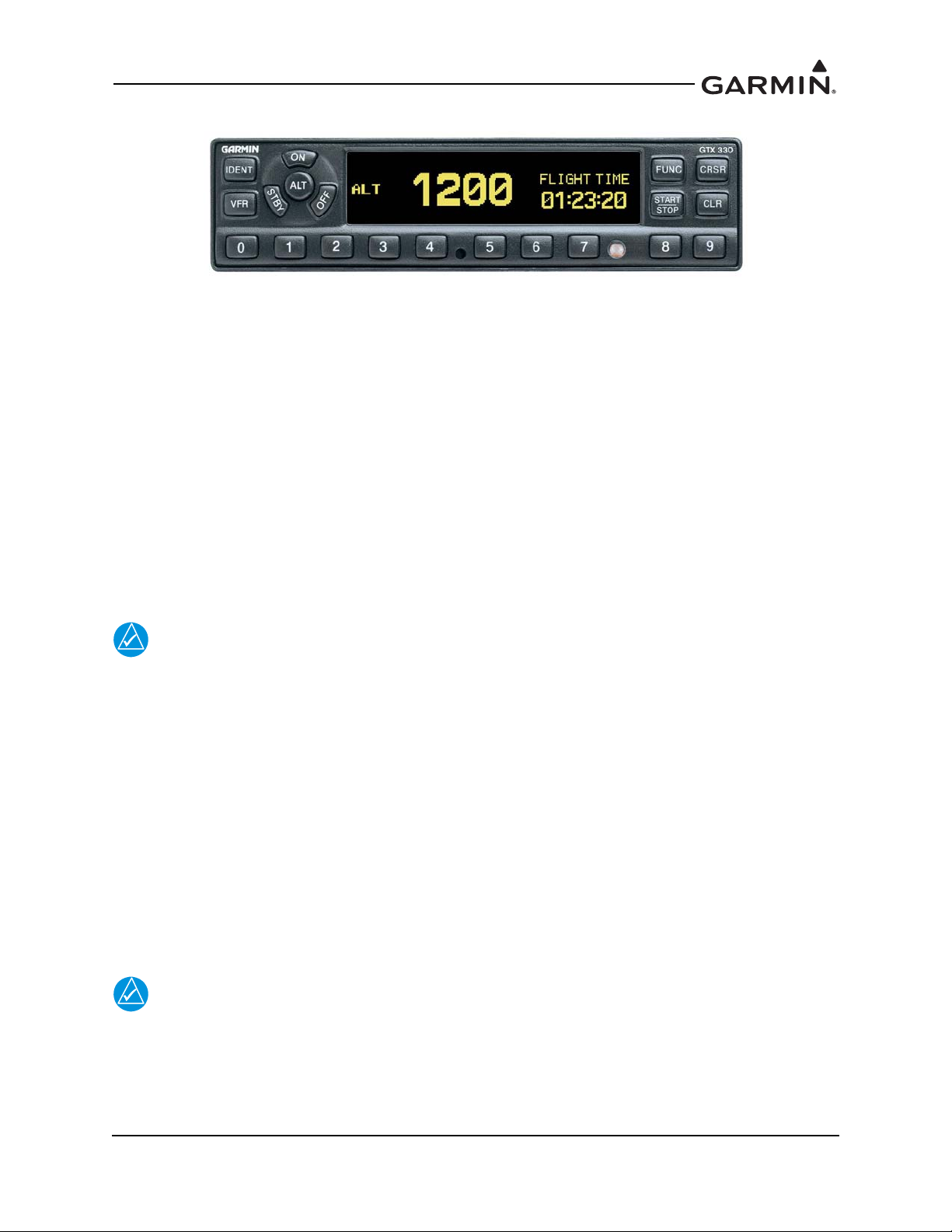
Figure 3-1 GTX 330/330D Front Panel
Function Selection Keys
The function selection keys are:
OFF Powers off the GTX 330.
STBY Selects the standby mode. Pressing the STBY key when the GTX 330 is powered off
automatically powers the unit on in standby mode. When in standby mode, the transponder
does not reply to interrogations. If using software v8.02 or later, GND mode is
automatically determined using either a squat switch or calculated data from various system
inputs including GPS data from an approved control/display unit such as a GTN 6XX/7XX,
GNS 400W/500W Series, or GNS 480.
ON Selects Mode A and Mode S. Pressing the ON key when the GTX 330 is powered off
automatically powers on the unit in Mode A and will transmit a squawk code when
interrogated.The transponder replies to Mode A and Mode S interrogations, as indicated by
the reply symbol (®). The replies do not include altitude information.
If the transponder is in the ON or ALT operating mode, the transponder becomes an active
part of the Air Traffic Control Radar Beacon System (ATCRBS). The transponder
responds to interrogations from TCAS equipped aircraft.
ALT Selects Mode A, Mode C, and Mode S. Pressing the ALT key when the GTX 330 is
powered off automatically powers on the unit in altitude reporting mode.The transponder
replies to identification, altitude and Mode S interrogations as indicated by the reply symbol
(®). Replies to altitude interrogations include the standard pressure altitude received from
an external altitude source, which is not adjusted for barometric pressure.
IDENT Pressing the IDENT key activates the Special Position Identification (SPI) Pulse for 18
seconds, identifying the transponder return from others on an air traffic controller’s screen.
During the IDENT period, the word “IDENT” appears in the upper left corner of the display.
VFR Sets the transponder code to the pre-programmed VFR code selected in Configuration mode
(Set to 1200 at the factory). Pressing the VFR key again restores the previous identification
code.
The VFR key is on (functional) by default, but can be disabled in configuration mode.
FUNC Changes the page shown on the right side of the display. Display data includes pressure
altitude, flight time, altitude monitor, count up, and count down timers. In the
Configuration mode, steps through the function pages.
190-00734-11 GTX 33X and GTX 3X5 ADS-B Maintenance Manual
Rev. 7 Page 3-2
Page 28

START/STOP Starts and stops the altitude monitor, count up, count down, and flight timers.
CRSR Initiates entry of the starting time for the count down timer and cancels transponder code
entry. Selects changeable fields in Configuration mode. If using software v8.02 or later,
holding the CRSR key during power on will place the unit into a Ground Test mode that
forces the aircraft into an airborne status for testing purposes.
CLR Resets the count up, count down, and flight timers. Cancels the previous key press during
code selection and count down entry. Used in Configuration mode.
8 Reduces contrast and display brightness when the respective fields are displayed and
enters the number eight into the count down timer. Used in Configuration mode.
9 Increases contrast and display brightness when the respective fields are displayed and
enters the number nine into the count down timer. Used in Configuration mode.
Code Selection
Code selection is entered with eight keys (0 – 7) providing 4,096 active identification codes. Pushing one
of these keys begins the code selection sequence. The new code is not activated until the fourth digit is
entered. Pressing the CLR key moves the cursor back to the previous digit. Pressing the CLR key when
the cursor is on the first digit of the code, or pressing the CRSR key during code entry, removes the cursor
and cancels data entry, restoring the previous code. You may press the CLR key up to five seconds after
code entry is complete to return the cursor to the fourth digit. The numbers 8 and 9 are not used for code
entry, only for entering a count down time, contrast and display brightness, and data selection in the
Configuration mode.
Function Display
PRESSURE ALT Displays the altitude data supplied to the GTX 330 in feet, hundreds of
feet (flight level), or meters, depending on configuration.
FLIGHT TIME Displays the flight time, controlled by the START/STOP key or by one
of four airborne sources (squat switch, GPS ground speed recognition, air
data airspeed recognition, or altitude increase) as configured during
installation. The timer begins when the GTX 330 determines that the
aircraft is airborne.
ALT MONITOR Controlled by START/STOP key. Activates a voice alarm and warning
annunciator when altitude limit is exceeded.
OAT/DALT Displayed when the GTX 330 is configured with temperature input.
Displays outside air temperature and density altitude.
COUNT UP Timer controlled by START/STOP and
COUNT DOWN Timer controlled by START/STOP, CLR, and CRSR keys. The initial
count down time is entered with the 0 – 9 keys.
CONTRAST This page is only displayed if manual contrast mode is selected in
Configuration mode. Contrast is controlled by the 8 and 9 keys.
DISPLAY This page is only displayed if manual backlighting mode is selected in
Configuration mode. Backlighting is controlled by the 8 and 9 keys.
ADS-B TX Controlled by START/STOP key. Starts/stops extended squitter
function.
FLIGHT ID If the GTX 33X is using software v8.02 or later and the system is
configured to allow the pilot to edit the flight ID, then the flight ID may
be entered using the CRSR key. Otherwise the flight ID is set in
configuration mode and cannot be changed during normal operation.
CLR keys.
190-00734-11 GTX 33X and GTX 3X5 ADS-B Maintenance Manual
Rev. 7 Page 3-3
Page 29

3.2 GTX 335/335D/345/345D
NOTE
Figure 3-2 GTX 335/335D/345/345D Front Panel
Function Selection Keys
The function selection keys are:
OFF Powers off the GTX 3X5.
STBY Selects the Standby mode. Pressing the STBY key when the GTX 3X5 is powered off
automatically powers the unit on in standby mode. When in Standby mode, the transponder
does not reply to interrogations but new codes can be entered and a SBY indication appears
on the display.
ON Selects the On mode, which generates Mode A and Mode S replies, but Mode C altitude
reporting is inhibited. Pressing the ON key when the GTX 3X5 is powered off automatically
powers on the unit in Mode A and will transmit a squawk code when interrogated. ADS-B
Out will not return barometric altitude as it switches to GPS altitude in this mode.
Interrogations are indicated by the reply symbol (®). The replies do not include altitude
information.
If the transponder is in the ON or ALT operating mode, the transponder becomes an active
part of the Air Traffic Control Radar Beacon System (ATCRBS). The transponder
responds to interrogations from TCAS equipped aircraft.
ALT Altitude mode is automatically selected when the aircraft becomes airborne using the unit’s
air/ground logic or when the ALT key is pressed. Pressing the ALT key when the
GTX 3X5 is powered off automatically powers on the unit in altitude reporting mode. While
the aircraft is on the ground and in ALT mode, the transponder does not allow Mode A and
Mode C replies, but it does permit acquisition squitter and replies to Mode S interrogations.
While the aircraft is in ALT mode and airborne, it will generate Mode A, Mode C and Mode
S replies as well as transmit acquisition and extended squitter, including ADS-B Out.
All transponder interrogations are indicated by the reply symbol (®).
IDENT Pressing the IDENT key activates the Special Position Identification (SPI) Pulse for 18
seconds, identifying the transponder return from others on an air traffic controller’s screen.
During the IDENT period, the word “IDENT” appears in the upper left corner of the display.
VFR Sets the transponder code to the pre-programmed VFR code selected in Configuration mode
(Set to 1200 at the factory). Pressing the VFR key again restores the previous identification
code.
190-00734-11 GTX 33X and GTX 3X5 ADS-B Maintenance Manual
Rev. 7 Page 3-4
Page 30

FUNC In normal mode, pressing the FUNC key changes the subpage group shown on the right side
of the display. Subpages include flight ID, pressure altitude, flight time, altitude monitor,
system count up, and count down timers. In the Configuration mode, steps through the
function pages.
ENT Confirms entry for selected item and moves the cursor to the next editable item, or function
selection, in configuration and normal operation. Starts and stops the altitude monitor, count
up, count down, and flight timers.
CRSR Selects changeable fields in configuration and normal operation. Initiates entry of the
starting time for the count down timer and cancels transponder code entry. Holding the
CRSR key during power on will place the unit into a Ground Test mode that forces the
aircraft into an airborne status for testing purposes.
CLR Resets the count up, count down and flight timers. Cancels the previous key press during
code selection, count down entry, or flight ID entry. Used in Configuration mode to scroll
through the function pages.
8 Used as a scroll-up key to navigate through page groups in normal and configuration mode.
9 Used as a scroll-down key to navigate through page groups in normal and configuration
mode.
Code Selection
Code selection is entered with eight keys (0 – 7) providing 4,096 active identification codes. Pushing one
of these keys begins the code selection sequence. The new code is not activated until the fourth digit is
entered. Pressing the CLR key moves the cursor back to the previous digit. Pressing the CLR key when
the cursor is on the first digit of the code, or pressing the CRSR key during code entry, removes the cursor
and cancels data entry, restoring the previous code. The numbers 8 and 9 are not used for code entry, only
for flight ID entry, count down time, aircraft tail number entry, and data selection in Configuration and
Normal mode.
Configuration Mode
To enter configuration mode, press and hold the ENT key, then energize the unit. To exit configuration
mode, press and hold the OFF key until the unit de-energizes.
To cycle through the pages, press the FUNC key
To access items on the page, press the CRSR key
To cycle through the selections of an item on the page, press the 8 or 9 key
To scroll up or down on the page when nothing is selected, press the 8 or 9 key
To move within the page, press the ENT key
To move to previous selection on the page, press the CLR key
To exit the page, press the FUNC key
GTX 3X5 units may also be configured using the GTX 3X5 Install Tool. For configuration using the
GTX 3X5 Install Tool, refer to Section 3.5.
190-00734-11 GTX 33X and GTX 3X5 ADS-B Maintenance Manual
Rev. 7 Page 3-5
Page 31

Function Display
FLIGHT ID If ALLOW PILOT TO EDIT FLT ID is configured to YES, the FLIGHT ID
can be changed by the pilot at any time in normal mode. This allows the pilot/
crew to enter the specific flight ID for transmission to ATC interrogations.
UP COUNTER Timer controlled by ENT and CLR keys.
DOWN COUNTER Timer controlled by ENT, CLR, and CRSR keys. The initial count down time
is entered with the 0 – 9 keys.
FLIGHT TIMER Displays the Flight Time, controlled by the ENT key or by one of four
airborne sources (squat switch, GPS ground speed recognition, air data
airspeed recognition, or altitude increase) as configured during installation.
The timer begins when the GTX 3X5 determines that the aircraft is airborne.
TRIP TIMER Timer controlled by ENT and CLR keys.
PRESSURE ALT Displays the altitude data supplied to the GTX 3X5 in feet, hundreds of feet
(flight level), or meters, depending on configuration.
ALT MONITOR Controlled by ENT key. Activates a voice alarm and warning annunciator
when altitude limit is exceeded.
SAT/DALT Displayed when the GTX 3X5 is configured with temperature input. Displays
Static Air Temperature and Density Altitude.
CONTRAST/OFFSET Contrast is controlled by the 8 and 9 keys.
BACKLIGHT/OFFSET This page is only displayed if photocell backlighting mode is selected in
Configuration mode. Backlighting is controlled by the 8 and 9 keys.
MESSAGES Alerts crew of transponder faults, fails and advisory messages. MSG appears
when a message is generated. CRSR and ENT keys access messages for
acknowledgment and viewing.
BLUETOOTH This page is only displayed on the GTX 345/345D when configured for
Bluetooth at installation. When enabled, allows PED pairing to the GTX 345/
345D and device management for display of ADS-B In data.
INTERNAL GPS This page displays Lat/Long accuracy, number of connected satellites,
horizontal figure of merit, whether the unit is using internal GPS, and overall
status.
1090ES TX CTRL This is only displayed when the unit is configured for 1090ES OUT
CONTROL in Configuration mode to be PILOT SET. Once configured, this
can be highlighted by the CRSR key, changed by the 8 and 9 keys, and
selected by ENT key. Turns the extended squitter function on or off.
190-00734-11 GTX 33X and GTX 3X5 ADS-B Maintenance Manual
Rev. 7 Page 3-6
Page 32

3.3 GTX 33/33D and GTX 335R/335DR/345R/345DR
Figure 3-3, Figure 3-4, and Figure 3-5 show the GTX control pages associated with the GTN 6XX/7XX
and GNS 480. Refer to the specific pilot guide and cockpit reference guide for details regarding control
and function. Part numbers for these documents are listed in Table 1-1.
Figure 3-3 GTN 7XX Transponder Control
Figure 3-4 GTN 6XX Transponder Control
Figure 3-5 GNS 480 Transponder Control
190-00734-11 GTX 33X and GTX 3X5 ADS-B Maintenance Manual
Rev. 7 Page 3-7
Page 33

3.4 GTX 335R/335DR/345R/345DR with Legacy G1000
With specific installations, the GDU 1XXX (of the G1000 system) provides control and operation of the
remote mounted GTX 335R/335DR/345R/345DR units. Figure 3-6 and Figure 3-7 display screen shots of
the GTX control pages associated with the G1000 system.
Refer to the specific aircrafts pilot guide for generic G1000 transponder control and functionality. In
addition to the generic transponder operation, functionality has changed to incorporate the GTX 3X5
interface as follows.
Functions:
GND The GND soft key is unavailable with the GTX 3X5 transponders. “XPDR GND
UNAVL” will annunciate any time the GND soft key is pressed and the unit will
revert to the previous mode the unit was in prior to the GND soft key being
pressed.
ADS-B TX The transmission of the ADS-B information is enabled/disabled by pressing the
ADS-B TX soft key. ADS-B transmission defaults to enabled at each power cycle.
In older GDU 1XXX software versions, the ADS-B TX soft key is not available;
this function defaults to enabled. Do not disable ADS-B transmission unless
requested by ATC.
Annunciations:
ADS-B Fail Any time the ADS-B Out system fails or the GPS signal is degraded, an ADS-B
Fail message will annunciate.
XPDR GND UNAVL Any time the GND soft key is pressed the advisory message will annunciate to
alert the ground mode is no longer available.
190-00734-11 GTX 33X and GTX 3X5 ADS-B Maintenance Manual
Rev. 7 Page 3-8
Page 34

Figure 3-6 G1000 Transponder Control
Figure 3-7 G1000 Transponder Control
190-00734-11 GTX 33X and GTX 3X5 ADS-B Maintenance Manual
Rev. 7 Page 3-9
Page 35

3.5 GTX 3X5 Install Tool
NOTE
NOTE
USB-A
USB-B
If the GTX 3X5 is configured to interface with a display control unit, the display control
unit must be turned off or in configuration mode prior to running the GTX 3X5 Install
Tool.
The GTX 3X5 Install Tool pages shown within this manual may reflect older GTX 3X5
Install Tool versions. Some differences in operation may be observed when comparing
information in this manual to later versions of the install tool.
The GTX 3X5 Install Tool is available for download from the Garmin
GTX 3X5 Install Tool requires a computer with available USB 2.0 ports and Microsoft Windows XP or
later.
A USB A-to-B cable is required to interface between a computer and the GTX 3X5. For additional details,
refer to Figure 3-8. To use the GTX 3X5 Install Tool, remove power from the GTX 3X5. Remove power
from the display control unit or verify it is in configuration mode. Connect the USB cable between the
GTX 3X5 and the computer. Energize the GTX 3X5 and then run the GTX 3X5 Install Tool.
Figure 3-8 USB A and USB B Connectors
The install tool is used to check equipment status, load software, and configure the unit. To put a
GTX 3X5 unit in configuration mode, change “Normal Mode” to “Configuration Mode” in the unit mode
window. Click the Set key to enter configuration mode.
Green boxes indicate a function operating correctly. Red boxes indicated a failure. Yellow boxes indicate a
fault or warning. Gray boxes indicate the presence of a pilot alert.
Dealer Resource Center. The
The bottom of the install tool displays unit information such as software version, connection status, and
unit mode. The tool will also annunciate if alerts, faults, failures, or warnings exist. The menu bar at the top
of the install tool has a GTX key and a Help key. The GTX key provides the following options:
• Save configuration
• Load configuration
• Reset configuration
• Push configuration from install tool to configuration module
•Exit
The Help key provides the following information:
• Part number
• Version number
• Copyright statement
• Software license agreements.
190-00734-11 GTX 33X and GTX 3X5 ADS-B Maintenance Manual
Rev. 7 Page 3-10
Page 36

3.5.1 State Page
The State page of the GTX 3X5 Install Tool reports the current mode of the GTX 3X5, Flight ID, Squawk
Code, and Pressure Altitude. This page allows selection of Ground Test and Traffic Test modes. This page
also allows selection of Standby or Operate TCAS Modes.
Figure 3-9 GTX 3X5 State Page
190-00734-11 GTX 33X and GTX 3X5 ADS-B Maintenance Manual
Rev. 7 Page 3-11
Page 37

3.5.2 Status Page
The Status page reports failures, faults, warnings, and pilot alerts. Information such as whether there is a
configuration module present is also displayed.
Figure 3-10 GTX 3X5 Status Page
190-00734-11 GTX 33X and GTX 3X5 ADS-B Maintenance Manual
Rev. 7 Page 3-12
Page 38

3.5.3 Configuration Group
The Configuration group contains the following pages:
Aircraft page - configuration of basic aircraft configuration and flight ID settings
Airframe page - configuration of basic airframe configuration and operational options settings
Unit page - configuration of identification code, unit options, and display options
Interfaces page - configuration of serial, A429, discretes, and HSDB settings
Sensors page - configuration of Garmin altitude encoder, GPS, internal AHRS, and additional
sensors
Audio page - configuration of audio options and alerts
Display page - configuration of display and key backlight, photocell and lighting bus curves, and
default offsets
All configurable settings must match GTX System Configuration Log retained in the aircraft permanent
records.
Figure 3-11 GTX 3X5 Configuration Group
190-00734-11 GTX 33X and GTX 3X5 ADS-B Maintenance Manual
Rev. 7 Page 3-13
Page 39

3.5.4 Diagnostics Group
NOTE
GTX 3X5 must be in configuration mode to view connection status or get assert log.
The Diagnostics group contains the following pages:
DAP - reports status of the necessary data supporting ADS-B requirements
Discretes - reports status of discrete inputs, outputs, and allows the user to override the Output pins
for testing purposes
Connection status - reports status of A429 inputs, serial inputs, and HSDB
Internal GPS - reports GPS acquisition status and signal strength
Bluetooth - reports Bluetooth receiver status and paired devices
Assert log - provides ability to download assert log for system troubleshooting
Figure 3-12 GTX 3X5 Diagnostics Group
190-00734-11 GTX 33X and GTX 3X5 ADS-B Maintenance Manual
Rev. 7 Page 3-14
Page 40

3.5.5 Product Data Group
The product data group provides the following pages.
Transponder page - displays basic system, FPGA, Boot Block, and Audio Database information
ADS-B In page - displays basic system, FPGA, and Boot Block information
GPS page - displays GPS and GPS loader information
Garmin Altitude Encoder page - displays altitude encoder serial number
Configuration page - displays configuration status of aircraft, unit, wiring, and display CRCs
Figure 3-13 GTX 3X5 Product Data Group
3.5.6 Software Upload
Refer to Section 7.3 for details.
190-00734-11 GTX 33X and GTX 3X5 ADS-B Maintenance Manual
Rev. 7 Page 3-15
Page 41

4 INSTRUCTIONS FOR CONTINUED AIRWORTHINESS
4.1 Applicability .....................................................................................................................................4-2
4.2 Airworthiness Limitations ................................................................................................................4-2
4.3 Servicing Information .......................................................................................................................4-3
4.3.1 On Condition Servicing..............................................................................................................4-3
4.3.2 Special Tools ..............................................................................................................................4-3
4.4 Maintenance Intervals.......................................................................................................................4-4
4.5 Visual Inspection ..............................................................................................................................4-5
4.6 Electrical Bonding Test ....................................................................................................................4-7
4.7 Additional Instructions .....................................................................................................................4-7
This section provides Instructions for Continued Airworthiness for the GTX 33X and GTX 3X5 with
ADS-B installation. This section satisfies the requirements for continued airworthiness as defined by 14
CFR Part 23.1529 and Part 23 appendix G. Information in this section is required to maintain the continued
airworthiness of the GTX 33X and GTX 3X5 as installed under this AML STC.
190-00734-11 GTX 33X and GTX 3X5 ADS-B Maintenance Manual
Rev. 7 Page 4-1
Page 42

Page 43

4.3 Servicing Information
GTX 33X and GTX 3X5 LRU maintenance is “on condition” only. Component-level overhaul is not
required for the GTX 33X and GTX 3X5 with ADS-B installation.
4.3.1 On Condition Servicing
On Condition replacement and/or servicing should occur when an item exhibits conditions, symptoms,
and/or abnormalities as defined in Section 5 of this manual. Replacement and/or servicing should be made
only after the technician troubleshoots the system by using the guidance in this manual along with common
avionics maintenance practices.
4.3.2 Special Tools
The following tools are needed to perform maintenance tasks.
Calibrated milliohm meter with an accuracy of +
Calibrated transponder ramp tester
Calibrated Pitot/static ramp tester
GTX 3X5 Install Tool (remote units only)
50 Ω 5 watt antenna load
0.1 milliohm or better
190-00734-11 GTX 33X and GTX 3X5 ADS-B Maintenance Manual
Rev. 7 Page 4-3
Page 44

4.4 Maintenance Intervals
NOTE
Table 4-1 shows systems and components, installed by this STC, which must undergo tests or checks at
specific intervals. The inspections based on calendar elapsed time have specifically stated intervals.
The maintenance intervals listed in the table below must be adhered to for each installed
GTX.
Table 4-1 Maintenance Intervals
Item Description/Procedure Section Interval
Equipment Removal
and Reinstallation
Cleaning
Antenna Visual
Inspection
Lightning Strike Actual or Suspected
Removal and reinstallation of GTX
LRUs.
The GTX 330 and GTX 335/335D/345/
345D display and bezel may be
cleaned periodically.
Cleaning is accomplished using a soft
cotton cloth dampened with clean
water.
DO NOT use any chemical cleaning
agents. Avoid scratching the surface of
the display.
Removal and replacement.
Inspect the coaxial cable connections,
GTX bonding hardware (including
bonding straps and tape), antenna, and
surrounding areas.
The GTX 33/330 and GTX 3X5 receiver
sensitivity must be tested and shown to
comply with Title 14 CFR Part 43
Appendix F.
6
N/A
4.5
4.5
4.
On Condition
On Condition
On Condition
On Condition
On Condition
Testing
Equipment Visual
Inspection
Testing
Electrical Bonding Test
The GTX 33/330 and GTX 3X5 must be
tested and shown to comply with Title
14 CFR Part 91.227.
A visual inspection of the equipment
installed by this STC must be
performed.
The GTX 33/330 and GTX 3X5 must be
tested and shown to comply with Title
14 CFR Part 91.411, 91.413, and Part
43 Appendix E and F.
An electrical bonding test must be
performed on equipment installed by
this STC.
8.7
4.5
4.
4.6
Replacement of GPS
Position source(s).
12 Calendar Months
Refer to Title 14 CFR
Part 91.411, 91.413,
and Part 43 Appendix
E and F.
10 Years or 2000
hours
190-00734-11 GTX 33X and GTX 3X5 ADS-B Maintenance Manual
Rev. 7 Page 4-4
Page 45

4.5 Visual Inspection
Perform a visual inspection in accordance with requirements in this section. Check for corrosion, damage,
or other defects for each of the installed items. Replace any damaged parts as required. Inspection may
require the temporary removal of a unit or units to gain access to connectors. Follow guidance in Section 6
for equipment removal and replacement. Refer to Appendix A of this manual for equipment locations.
Refer to the specific Aircraft Maintenance Manual for instructions on removing any access panels.
GTX 330/330D/335/335D/345/345D Visual Inspection
During normal aircraft inspections not to exceed 12 calendar month intervals, conduct a visual inspection
of the GTX 330/330D/335/335D/345/345D installation in the following locations.
Instrument Panel
1. Inspect all GTX 330/330D/335/335D/345/345D keys for legibility of labels and markings.
2. Inspect GTX 330/330D/335/335D/345/345D units for security of attachment.
3. Inspect mounting rack and hardware for integrity.
a. Verify the racks, fasteners, and support structure are in good condition and securely fastened.
b. Inspect for signs of corrosion.
c. For composite aircraft, inspect any aluminum foil tape used to ground the GTX and verify that
it is not torn, damaged, or showing signs of corrosion. If any of these occur then the tape must
be replaced. Refer to Appendix B for details.
4. Inspect any bonding straps for corrosion, loose connections, or signs of damage. Refer to
Appendix B for details.
5. Inspect the condition of the wiring harnesses and coaxial cables.
a. Inspect all instrument panel wiring and coax for chafing, damage, proper routing of wire
bundles and security of attachment in accordance with AC 43.13-1B, chapter 11, section 8,
paragraph 11-96. Pay particular attention to possible areas of chafing.
b. Verify that the harness shows no signs of cracking, chafing, abrasion, melting, or any other
form of damage.
c. Inspect the GTX 330/330D/335/335D/345/345D connectors for corrosion or other defects.
Check the integrity of the shield block ground attachments to the harness connector assembly
as well as the integrity of the individual shields and their attachment.
190-00734-11 GTX 33X and GTX 3X5 ADS-B Maintenance Manual
Rev. 7 Page 4-5
Page 46

GTX 33/33D/335R/335DR/345R/345DR Visual Inspection
During normal aircraft inspections not to exceed 12 calendar month intervals, conduct a visual inspection
of the GTX 33/33D/335R/335DR/345R/345DR installation in the following locations.
Remote Mount Rack
1. Inspect GTX 33/33D/335R/335DR/345R/345DR units for security of attachment.
2. Inspect mounting rack and hardware for integrity.
a. Verify the racks, fasteners, and support structure are in good condition and are securely
fastened.
b. Inspect for signs of corrosion.
c. For composite aircraft, inspect any aluminum foil tape used to ground the GTX and verify that
it is not torn, damaged, or showing signs of corrosion. If any of these occur then the tape must
be replaced. Refer to Appendix B for details.
3. Inspect any bonding straps for corrosion, loose connections, or signs of damage. Refer to
Appendix B for details.
4. Inspect the condition of the wiring harnesses and coaxial cables.
a. Verify that all wiring and cables are securely fastened.
b. Verify that the harness shows no signs of cracking, chaffing, abrasion, melting, or any other
form of damage.
c. Inspect the GTX 33/33D/335R/335DR/345R/345DR connectors for corrosion or other
defects. Check the integrity of the shield block ground attachments to the harness connector
assembly as well as the integrity of the individual shields and their attachment.
Antenna Visual Inspection
During normal aircraft inspections not to exceed 12 calendar month intervals, conduct a visual inspection
of the transponder antennas for the following.
1. Erosion, cracks, dents, or broken antenna. If these conditions are present, antenna must be
replaced. Refer to antenna manufacturer’s replacement instructions for details.
2. If the attachment is not secure, re-work the installation and complete electrical bonding test
specified in Section 4.6.
3. Condition of base seals. In the event the antenna seal shows sign of damage or decomposition, reseal and complete the electrical bonding test specified in Section 4.6.
Post Lightning Strike Inspection
A post lightning strike inspection must be performed for a suspected or actual lightning strike to antennas
or any temperature sensor connected to the GTX unit. Inspect antenna or sensor and surrounding
installation to verify that structural damage has not occurred around the areas where lightning may have
attached. If there is visible sign of damage to the antenna or sensor, then it should be replaced.
Inspect the antenna coax connection to GTX unit, grounding hardware, bonding straps or tape, and
surrounding areas of the remotely mounted GTX to verify damage has not occurred. Repair any damaged
areas and components, then complete the electrical bonding test specified in Section 4.6.
190-00734-11 GTX 33X and GTX 3X5 ADS-B Maintenance Manual
Rev. 7 Page 4-6
Page 47

4.6 Electrical Bonding Test
1. Disconnect the antenna coaxial cable from the GTX 33X or GTX 3X5.
2. Disconnect all connectors from the GTX 33X or GTX 3X5.
3. Measure the DC resistance between each of the following test points and the aircraft ground
reference as defined in Table B-1 and verify the resistance is less than or equal to the appropriate
periodic test resistance value.
Top metal case of GTX 330/330D/335/335D/345/345D #1 (if installed)
Top metal case of GTX 330/330D/335/335D/345/345D #2 (if installed)
GTX 33/33D/335R/335DR/345R/345DR #1 chassis (if installed)
GTX 33/33D/335R/335DR/345R/345DR #2 chassis (if installed)
4. If the resistance is more than the periodic test resistance value in Table B-1, the bond must be
improved enough to meet the reconditioned resistance value.
4.7 Additional Instructions
Electrical load information for the GTX is provided in Section 2.6.
190-00734-11 GTX 33X and GTX 3X5 ADS-B Maintenance Manual
Rev. 7 Page 4-7
Page 48

5 TROUBLESHOOTING
5.1 GTX General Troubleshooting .........................................................................................................5-2
5.2 GTX Failure Annunciations..............................................................................................................5-4
5.3 GTX 33X Connector Pinout Information .......................................................................................5-11
5.3.1 GTX 33X (J3301).....................................................................................................................5-11
5.3.2 Altitude Functions ....................................................................................................................5-13
5.3.3 Discrete Functions ....................................................................................................................5-13
5.3.4 RS-232 Input/Output ................................................................................................................5-14
5.3.5 ARINC 429 Input/Output .........................................................................................................5-14
5.4 GTX 3X5 Connector Pinout Information .......................................................................................5-15
5.4.1 GTX 3X5 (J3251).....................................................................................................................5-15
5.4.2 GTX 345/345D/345R/345DR (J3252) .....................................................................................5-17
5.4.3 Altitude Functions ....................................................................................................................5-18
5.4.4 Discrete Functions ....................................................................................................................5-19
5.4.5 RS-232 Input/Output ................................................................................................................5-21
5.4.6 ARINC 429 Input/Output .........................................................................................................5-21
5.4.7 RS-422 Out...............................................................................................................................5-21
5.4.8 HSDB Input/Output..................................................................................................................5-22
190-00734-11 GTX 33X and GTX 3X5 ADS-B Maintenance Manual
Rev. 7 Page 5-1
Page 49

5.1 GTX General Troubleshooting
This section provides information to assist troubleshooting if problems occur after completing
maintenance. Refer to the GTX System Configuration Log retained in the aircraft permanent records for a
list of the interfaced equipment and system configuration data. When troubleshooting the GTX, refer to the
wire routing drawings and interconnect wiring diagrams that are retained in the aircraft permanent records.
The following table describes possible symptoms associated with the Garmin transponders and provides
corresponding actions for troubleshooting.
190-00734-11 GTX 33X and GTX 3X5 ADS-B Maintenance Manual
Rev. 7 Page 5-2
Page 50

Check and verify the
integrity of the
transponder-altitude
encoder interface,
including wiring and
altitude encoder
operation
Check and verify
integrity of the
antenna installation,
ground planes, and
coaxial cable
Ensure the XPDR
circuit breaker is
closed
Test coaxial cables for
insertion loss and VSWR.
VSWR should be checked
with an in-line type VSWR/
wattmeter inserted in the
coaxial transmission line
between the transponder and
the antenna. The VSWR
should be 1.5:1 at 1090 MHz
or less. Insertion loss should
be less than 1.5 dB at 1090
MHz
GTX Symptom
Transponder audio too quiet/
loud
Incorrect Mode S aircraft
data transm itted
Transponder will not turn
on
Transponder will not come
out of standby
Check for proper
electrical bonding/
grounding of the
antenna installation
Corrective
Action
Corrective
Action
Corrective
Action
Corrective
Action
Ensure transponder
is fully seated and
mated to the
connectors in the
mounting rack
Corrective
Action
Corrective
Action
If fault still exists,
contact Garmin.
Loss of, or incorrect altitude
reporting by the transponder
Verify transponder
select switch position,
(#1 or #2) if installed
Check the
configuration mode
settings and reset if
necessary
Verify that the GTX
volume setting is at or
above the minimum
required setting
Poor transponder
performance. Weak or
intermittent radar contact
reported by ATC
Verify connections
for power and ground
Verify the unswitched
audio input at the
audio panel setting is
at or above the
minimum required
setting
Check the altitude
source configuration
on the GTX. Verify
primary and secondary
sources are configured
properly.
Verify the Flight ID and
ICAO address are
configured properly
Verify the Tail number
and ICAO address are
properly configured
Figure 5-1 GTX (All Models) Transponder Troubleshooting
190-00734-11 GTX 33X and GTX 3X5 ADS-B Maintenance Manual
Rev. 7 Page 5-3
Page 51

5.2 GTX Failure Annunciations
Ensure the aircraft has a clear view of
the sky
GTX 330 Failure
Messages
NO ADSB
Transponder FAIL
message
Fatal Error Page Displayed
Cause
Corrective
Action
If fault still exists,
contact Garmin.
Ensure position source (GPS) is
powered and receiving valid GPS
position data
Ensure ADS-B TX is ON. This option
is only available if ADS-B TX is
configured for PILOT SET
Corrective
Action
Corrective
Action
Cause Cause
The internal transmit or
squitter monitors have
detected a failure
The transponder has
insufficient data to support
ADS-B Out transmission
The transponder has failed
the internal power up
integrity check
Reset the transponder. Check
connections, wiring, and coax cables
Reload software
Reset the transponder. Check
connections, wiring, and coax cables
Reload software
Figure 5-2 GTX 330/330D Transponder Failure/Fault Messages
190-00734-11 GTX 33X and GTX 3X5 ADS-B Maintenance Manual
Rev. 7 Page 5-4
Page 52

Verify ADS -B TX is on
and GPS source is
receiving valid GPS
position data
Verify GPS source
configuration is IAW
the Installation
Guidance
GTX 33 Failure
Messages
TRANSPONDER 1 –
ADSB is not
transmitting position
TRANSPONDER 2 –
ADSB is not
transmitting position
Verify the aircraft has a
clear view of the sky
The transponder has
insufficient data to
support ADS-B Out
transmission
Cause
The transponders are
configured for different
Mode S addresses
Corrective
Action
Corrective
Action
If fault s till exists ,
return to Garmin.
TRANSPONDER –
Transponder 1 and 2
Mode S addresses do
not match
Cause
The transponder is
reporting a system
failure
Corrective
Action
TRANSPONDER 1 –
Transponder 1 needs
service
Cause
The transponder is
reporting a system
failure
Corrective
Action
TRANSPONDER 2 –
Transponder 2 needs
service
Verify the Mode S
address for each
transponder and that
they match.
Cause
Verify RS-232 wiring
between GTN/GNS
and GTX
Check configuration of
GTX and GTN/GNS
TRANSPONDER 1 –
Transponder 1 is
inoperative or
connection to GTN/
GNS is lost
TRANSPONDER 2 –
Transponder 2 is
inoperative or
connection to GTN/
GNS is lost
If two transponders are
installed, ensure both
units are powered on
The GTN/GNS cannot
communicate with the
transponder or the
transponder is
reporting a system
failure
Corrective
Action
Cause Cause Cause
The GTN cannot
communica te with the
transponder or the
transponder is
reporting a system
failure
If two transponders are
installed, ensure both
units are powered on
Check configuration of
GTX and GTN/GNS
Verify RS-232 wiring
between GTN/GNS
and GTX
The transponder has
insufficient data to
support ADS-B Out
transmission
Corrective
Action
Corrective
Action
Verify ADS-B TX is on
and GPS source is
receiv ing valid GPS
position data
Verify GPS source
configuration is IAW
the Installation
Guidance
Verify the aircraft has a
clear view of the sky
Check configuration of
GTX and GTN/GNS
Check configuration of
GTX and GTN/GNS
Re-install the la test
software
Re-configure the GTX
Re-install the latest
software
Re-configure the GTX
Figure 5-3 GTX 33/33D Transponder Failure/Fault Messages
190-00734-11 GTX 33X and GTX 3X5 ADS-B Maintenance Manual
Rev. 7 Page 5-5
Page 53

GTX 3X5 Messages
If fa ult s till exists,
contact Garmin.
Transponder
Or
1090 ADS-B
Out
1090 MHz
Transm itter
Failure
1030 MHz
Rece ive r Fa ilure
Failure
IC AO A dd ress
Failure
- Lo ss, d am aged,
inc orre ct w irin g
- Incorre ct antenna
- Inte rnal fa ilure
ICA O add res s is
incorrect
Cause
Verify transponder
antenna,
connections, and
coa x ins tallation
Insp ect
suppression bus
wiring
Insp ect wiring
Re load softw are
Reset config and
config module
Reconfigure unit
Verify transponder
antenna,
connections, and
coa x ins tallation
Insp ect
suppression bus
wiring
Insp ect wiring
Re load softw are
Re set c onfig and
config module
Reconfigure unit
En ter p rope r ICAO
address.
Re load softw are
Corrective
Action
Transponder
Or
1090 ADS-B
Out
Fa ilure
Cause
- Loss, damaged,
inc orr ec t w iring
- Inco rrec t ante nna
- Inte rnal fa ilure
Corrective
Action
Transponder
Or
1090 ADS-B
Out
Fa ilure
Cause
Corrective
Action
Configuration
Fa ilure
Transponder
configuration data
is inv alid or
inc om ple te
Reload software
Re set c onfig and
co nfig modu le
Reconfigure unit
Ve rify the GTX
Insta ll tool
configuration
sum mary, correct
any errors
Transponder
Or
1090 ADS-B
Out
Failure
Cause
Corrective
Action
C alib ration
Fa ilure
Factory
transponder
calibration data
inv alid
Reload software
Reset config and
config module
Reconfigure unit
Verify transponder
antenna,
connections, and
coax installaiton
Insp ect wiring ,
suppression bus,
and connections
Transponder
Or
1090 ADS-B
Out
Fa ilure
Cause
Corrective
Action
E lec trica l F ailu re
Internal v oltag e
mis-com pare with
the unit
Reload software
Re set c onfig and
co nfig modu le
Reconfigure unit
Ve rify all w iring,
shorts/opens.
Ve rify po we r an d
ground
connections
Transponder
Or
1090 ADS-B
Out
Fa ilure
Cause
Corrective
Action
Frequency Lock
Fa ilure
FP G A ha s an erro r
Possible internal
hard ware issue
Reload software
Reset config and
config module
Reconfigure unit
Verify transponder
antenna,
connections, and
coax installation
Insp ect wiring ,
suppression bus,
and connections
Transponder
Or
1090 ADS-B
Out
Fa ilure
Cause
Corrective
Action
Squitter Monitor
Fa ilure
Erro r gene rating
Squ itter replies
Possible internal
hard ware issue
Reload software
Re set c onfig and
config module
Reconfigure unit
Verify transponder
antenna,
connections, and
coax installation
Insp ect wiring ,
suppression bus,
and connections
Transponder
Or
1090 ADS-B
Out
Failure
Cause
Corrective
Action
Re set c onfig and
config module
Reconfigure unit
190-00734-11 GTX 33X and GTX 3X5 ADS-B Maintenance Manual
Rev. 7 Page 5-6
Figure 5-4 GTX 3X5 Transponder Alerts
Sheet 1 of 5
Page 54

GTX 3X5 Messages
If fault still exists,
contact Garmin.
Transmit Monitor
Failure
FP GA Fa ilure
- 1090MHz
transmission
failure s,
- Internal hardware
problem
- Wiring p roblem
- Incompatible
antenna
FPGA software did
not load properly
Reload software
Reset config and
config module
Reconfigure unit
Verify antenna,
connections, and
coax installation
Insp ect wiring,
suppression bus,
and connections
Reload software
Reset config and
config module
Reconfigure unit
Verify antenna,
connections, and
coax installation
Inspect wiring,
suppression bus,
and connections
Transponder
Or
1090 ADS-B
Out
Transponder
Or
1090 ADS-B
Out
Failure
Failure
Cause Cause
Corrective
Action
Corrective
Action
Maximum
Temperature
Exceeded
Minimum
Temperature
Exceeded
Low Temperature
Failure
High
Temperature
Failure
Internal
Temperature has
exceeded limits.
Possible internal
damage may have
occured
Bring GTX within
operating
temperature listed
on the EQF
Bring GTX within
operating
temperature listed
on the EQF
Internal
Temperature has
exceeded limits.
Possible internal
damage may have
occured
Failu re Failure
Cause Cause
Corrective
Action
Corrective
Action
High
Temperature
Failure
Low Temperature
Failure
Internal
Temperature has
exceeded limits,
possible internal
damage may have
occurred
Bring GTX within
operating
temperature listed
on the EQF
Bring GTX within
operating
temperature listed
on the EQF
Internal
Temperature has
exceeded limits,
possible internal
damage may have
occurred
Transponder
Or
1090 ADS-B
Out
Transponder
Or
1090 ADS-B
Out
Failure Failure
Cause Cause
Corrective
Action
Corrective
Action
RAM Failure
Software load
issue or internal
hardware issue
Reload software
Transponder
Or
1090 ADS-B
Out
Failure
Cause
Corrective
Action
Transponder
FPGA ROM
Failure
FPGA software
load issue
Reload software
Transponder
Or
1090 ADS-B
Out
Failure
Cause
Corrective
Action
Transponder
RO M Failu re
Software load
issue
Reload software
Transponder
Or
1090 ADS-B
Out
Failure
Cause
Corrective
Action
Reset config and
config module
Reconfigure unit
Reset config and
config module
Reconfigure unit
Reset config and
config module
Reconfigure unit
Figure 5-4 GTX 3X5 Transponder Alerts
Sheet 2 of 5
190-00734-11 GTX 33X and GTX 3X5 ADS-B Maintenance Manual
Rev. 7 Page 5-7
Page 55

GTX 3X5 Messages
If fau lt still ex ists ,
contact Garmin.
Pressure
Altitude
Pressure
Altitude Input
Warning
Ground Test
Ground Test
Mode
Pressure altitude
is not va lid
Verify GTX and
pressure sensor are
properly configured
Verify w iring from
pressure sensor
Verify p ressure
sensor is functioning
If using the GA E,
verify connections
and then recalibrate
Reload software
System in ground
test mode
Power cycle the GTX
Warning
Cause
Corrective
Action
Alert
Cause
Corrective
Action
TAS/TCAS
TAS/TCAS
Inpu t Wa rning
TAS/TCAS is configured
on the GTX and no data
is received or the TAS/
TCAS system is reporting
a failure .
Verify TAS/TCAS
system has the required
and valid data (i.e.
Position, Altitude,
Heading, etc.)
Verify w iring w ith TAS/
TCAS system
Verify th e TAS /TCA S is
configured properly
Verify the TAS/TCAS
system has not failed
Warning
Cause
Corrective
Action
ADS-B
Position Input
No ADS-B
Position Input
Warning
GPS position
unavailable with ADS-B
In and/or Out enabled.
(for ADS-B Out, the unit
is not in standby)
Verify GPS antenna is
SBAS compatible
Verify position source is
available, powered on,
and properly configured
Verify GPS antenna
has cle ar view of the
sky
Warning
Cause
Corrective
Action
Reset config and
config module
Reconfigure unit
ADS-B In
Traffic
Alerting
CSA Fault
Traffic
Traffic
Processing
Fault
Traffic
AD S-B In
Communicatio
n Fault
ADS-B IN processing is enabled and
the input data does not meet the
performance specifications.
- GPS horizontal position unavailable
- GPS velocity unavailable
- GP S time u navailab le
- HFOM must be better than 0.5NM
- Pressure altitude unavailable or GPS
altitude and VFOM worse than 45m
Verify valid GPS antenna has
clear view of the sky
Position source is available,
properly configured and powered
Verify ADS-B In traffic is properly
installed and configured,
display source,
heading source,
GPS source
Are all configured properly
Reset configuration and
configuration module, then
reconfigure unit
Reload software
ADS-B In is enabled and an additional
fault ha s occure d.
- ADS-B / ADS-R / TIS-B Fault
- TAS/TCAS Input Warning
- CSA Fault
- GPS Fault
- Pressure Altitude Warning
- ADS -B In E lectrical Fa ult
- Internal communication between the
main and ADS-B boards
Insp ect co mpa tibility of
transponder antenna and
connections
Verify the position source is
available, powered on and
properly configured
Reset configuration and
configuration module, then
reconfigure unit
Reload software
Verify TAS/TCAS system is
not failed
ADS-B In is enabled and an additional
fault ha s occure d.
- ADS -B / AD S-R / T IS-B Fa ult
- TAS/TCAS Input Warning
- CSA Fault
- GPS Fault
- Pressure Altitude Warning
- ADS -B In E lectrical Fa ult
- Internal communication between the
main and ADS-B boards
Fault
Cause
Corrective
Action
Fault Fault
Cause Cause
Corrective
Action
Corrective
Action
Insp ect co mpa tibility of
transponder antenna and
connections
Reset configuration and
configuration module, then
reconfigure unit
Reload software
Verify TAS/TCAS system is
not faile d
Verify the position source is
available, powered on and
properly configured
190-00734-11 GTX 33X and GTX 3X5 ADS-B Maintenance Manual
Rev. 7 Page 5-8
Figure 5-4 GTX 3X5 Transponder Alerts
Sheet 3 of 5
Page 56

GTX 3X5 Messages
If fault still exists ,
contact Garmin.
ADS-B IN
ADS-B/ADS-R/
TIS-B Fault
1090
ADS-B In
1090 RX Fault
UAT
ADS-B In
978 RX Fault
ADS-B In enabled
and both 1090
MHz and 978 MHz
receivers failed
Verify antenna is
compatible
Reload software
Inspect all wiring,
and coaxial cables
ADS-B In enabled
and the 1090 MHz
receiver failed
Verify antenna is
com pa tible
Reload software
Inspect all wiring,
and coaxial cables
ADS-B In enabled
and the 978 MHz
receiver failed
Inspect
compatibility of
transponder
antenna and
connections
Reload software
Fault
Cause
Corrective
Action
Fault
Cause
Corrective
Action
Fault
Cause
Corrective
Action
FIS-B
Weather
978 RX Fault
FIS-B
Weather
ADS-B In
Communicatio
n Fault
FIS-B enabled
and the 978 MHz
receiver failed
Inspect
com pa tibility of
transponder
antenna and
connections
FIS-B enabled and
the 978 MHz
receiver failed
Inspect
com pa tibility of
transponder
antenna and
connections
Reload software
Fault
Cause
Corrective
Action
Fault
Cause
Corrective
Action
ADS-B In
Configuration
Fault
ADS-B In
configuration data
did not load or is
invalid
Service Soon
Fault
Cause
Corrective
Action
ADS-B In
Electrical Fault
ADS-B In
Calibration
Fault
Reload software
Electrical fault with
the ADS-B board.
Possible internal
hardware problem.
Check wiring
Factory ADS-B In
calibration data is
inva lid
Reload software
Service SoonService Soon
Fault
Cause
Fault
Cause
Corrective
Action
Corrective
Action
Reset config and
config module
Reconfigure unit
Reset config and
config module
Reconfigure unit
Reset config and
config module
Reconfigure unit
Reset config and
config module
Reconfigure unit
Reset config and
config module
Reconfigure unit
Reset config and
config module
Reconfigure unit
Reload software
Reset config and
config module
Reconfigure unit
Reset config and
config module
Reconfigure unit
Reload software
190-00734-11 GTX 33X and GTX 3X5 ADS-B Maintenance Manual
Rev. 7 Page 5-9
Figure 5-4 GTX 3X5 Transponder Alerts
Sheet 4 of 5
Page 57

GTX 3X5 Messages
If fault still ex ists,
contact Garmin.
GPS Fault
GAE
Calibration
Fault
Backlight
Calibration
Fault
Configuration
Module Fault
- No GPS data
available.
- Internal G PS fault
- Not connected to a
valid SBAS/GPS
source
Verify GPS
antenna is SBAS
compatible
Verify position
source is available
and properly
configured
Verify GPS
antenna has clear
view of the sky
Gar min A ltitude
Encoder (GAE)
calibration data is
invalid
Calibrate GAE
Factory calibration
for the dis play is
invalid
Verify lighting
configuration
Failure of the
configuration
module
Verify module is
installed and
wiring is correct
Service SoonService Soon
Fault
Cause
Fault
Cause
Service Soon Service Soon
Fault
Cause
Fault
Cause
Corrective
Action
Corrective
Action
Corrective
Action
Corrective
Action
Audio ROM
Fault
Non-volatile
Memory Fault
Audio database
did not load or is
invalid
Non-volatile data
did not load or is
invalid
Service SoonService Soon
FaultFault
CauseCause
Corrective
Action
Corrective
Action
Service Soon
Suppression
Bus Fault
Fault on the
suppression bus
Check for
incom patib le LR U
on suppression
line (D ME)
Verify su ppression
bus wiring for
shorts or opens
Fault
Cause
Corrective
Action
ADS-B In
FPGA ROM
Fault
ADS-B In FPGA
software did not
load or is invalid
Service Soon
Fault
Cause
Corrective
Action
Reset config and
config module
Reconfigure unit
AD S-B In ROM
Fault
ADS -B In softw are
did not load or is
invalid
Reload software
Service Soon
Fault
Cause
Corrective
Action
Reset config and
config module
Reconfigure unit
Reset config and
config module
Reconfigure unit
Reset config and
config module
Reconfigure unit
Reload software Reload software Reload software
Reset config and
config module
Reconfigure unit
Reload software
Reset config and
config module
Reconfigure unit
Reload software
Reset config and
config module
Reconfigure unit
Reload software
Figure 5-4 GTX 3X5 Transponder Alerts
Sheet 5 of 5
190-00734-11 GTX 33X and GTX 3X5 ADS-B Maintenance Manual
Rev. 7 Page 5-10
Page 58

5.3 GTX 33X Connector Pinout Information
59 58 57 56
5
5
54 53 52
51
43
44
50
49
48 47
46 45
62
61
60
25 24 23 22
26
27
282930
313233
34
353637
3839
404142
1
2
345678
9101113
14151617
12
1920
21
18
5.3.1 GTX 33X (J3301)
Figure 5-5 Rear View, Connector P3301
Table 5-1 GTX 33X Pinout
Pin GTX 33/33D Pin Name GTX 330/330D Pin Name I/O
1 RESERVED AVIONICS MASTER ON SELECT IN
2 ALTITUDE A1 ALTITUDE A1 IN
3 ALTITUDE C2 ALTITUDE C2 IN
4 ALTITUDE A2 ALTITUDE A2 IN
5 ALTITUDE A4 ALTITUDE A4 IN
6 ALTITUDE C4 ALTITUDE C4 IN
7 ALTITUDE B1 ALTITUDE B1 IN
8 ALTITUDE C1 ALTITUDE C1 IN
9 ALTITUDE B2 ALTITUDE B2 IN
10 ALTITUDE B4 ALTITUDE B4 IN
11 ALTITUDE D4 ALTITUDE D4 IN
12 EXTERNAL IDENT SELECT* EXTERNAL IDENT SELECT* IN
13 EXTERNAL STANDBY SELECT* EXTERNAL STANDBY SELECT* IN
14 NOT USED 28 V LIGHTING BUS HI IN
15 AUDIO OUT HI AUDIO OUT HI OUT
16 AUDIO OUT LO AUDIO OUT LO OUT
17 SQUAT SWITCH IN SQUAT SWITCH IN IN
18 RESERVED RESERVED --
19 ALTITUDE ALERT ANNUNCIATE* ALTITUDE ALERT ANNUNCIATE* OUT
20 RESERVED RESERVED --
21 AIRCRAFT POWER 1 AIRCRAFT POWER 1 IN
22 RS-232 IN 1 RS-232 IN 1 IN
23 RS-232 OUT 1 RS-232 OUT 1 OUT
24 RS-232 IN 2 RS-232 IN 2 IN
25 RS-232 OUT 2 RS-232 OUT 2 OUT
26 ARINC 429 IN 3 A ARINC 429 IN 3 A IN
27 POWER GROUND POWER GROUND --
28 ARINC 429 OUT 2 B ARINC 429 OUT 2 B OUT
29 ARINC 429 IN 3 B ARINC 429 IN 3 B IN
190-00734-11 GTX 33X and GTX 3X5 ADS-B Maintenance Manual
Rev. 7 Page 5-11
Page 59

Pin GTX 33/33D Pin Name GTX 330/330D Pin Name I/O
30 ARINC 429 OUT 2 A ARINC 429 OUT 2 A OUT
31 EXTERNAL SUPPRESSION I/O EXTERNAL SUPPRESSION I/O I/O
32 ARINC 429 IN 1 A ARINC 429 IN 1 A IN
33 ARINC 429 IN 2 A ARINC 429 IN 2 A IN
34 ARINC 429 OUT 1 B ARINC 429 OUT 1 B OUT
35 ARINC 429 IN 1 B ARINC 429 IN 1 B IN
36 ARINC 429 IN 2 B ARINC 429 IN 2 B IN
37 ARINC 429 OUT 1 A ARINC 429 OUT 1 A OUT
38 RESERVED RESERVED --
39 RESERVED RESERVED --
40 SPARE SPARE --
41 CURRENT TEMPERATURE PROBE OUT CURRENT TEMPERATURE PROBE OUT OUT
42 AIRCRAFT POWER 1 AIRCRAFT POWER 1 IN
43 POWER GROUND POWER GROUND --
44 CURRENT TEMPERATURE PROBE IN CURRENT TEMPERATURE PROBE IN IN
45 NOT USED 14 V/5 V LIGHTING BUS HI IN
46 TIS CONNECT SELECT* TIS CONNECT SELECT* IN
47 AUDIO MUTE SELECT* AUDIO MUTE SELECT* IN
48 ARINC 429 IN 4 A ARINC 429 IN 4 A IN
49 ARINC 429 IN 4 B ARINC 429 IN 4 B IN
50 ALTITUDE COMMON (GROUND) ALTITUDE COMMON (GROUND) IN
51 SIGNAL GROUND SIGNAL GROUND --
52 RESERVED RESERVED --
53 RESERVED RESERVED --
54 XPDR REMOTE POWER OFF RESERVED IN
55 NOT USED SPARE --
56 AIRCRAFT POWER 2 AIRCRAFT POWER 2 IN
57 NOT USED SPARE --
58 SIGNAL GROUND RESERVED --
59 NOT USED SPARE --
60 AIRCRAFT POWER 2 AIRCRAFT POWER 2 IN
61 NOT USED SPARE --
62 SWITCHED POWER OUT SWITCHED POWER OUT OUT
* Denotes Active-Low (Ground to activate)
190-00734-11 GTX 33X and GTX 3X5 ADS-B Maintenance Manual
Rev. 7 Page 5-12
Page 60

5.3.2 Altitude Functions
Gillham code altitude inputs are considered active if either the voltage to ground is < 1.9 V or the
resistance to ground is < 375 . These inputs are considered inactive if the voltage to ground is
11-33 VDC.
Table 5-2 GTX 33X Encoded Altitude Pin Assignments
Pin Name Pin Number I/O Unit (33X)
ALTITUDE D4 11 IN Both
ALTITUDE A1 2 IN Both
ALTITUDE A2 4 IN Both
ALTITUDE A4 5 IN Both
ALTITUDE B1 7 IN Both
ALTITUDE B2 9 IN Both
ALTITUDE B4 10 IN Both
ALTITUDE C1 8 IN Both
ALTITUDE C2 3 IN Both
ALTITUDE C4 6 IN Both
ALTITUDE COMMON 50 -- Both
5.3.3 Discrete Functions
Discrete Outputs
Table 5-3 GTX 33/330 Discrete Outputs
Pin Name Pin Number I/O Unit (33X)
ALTITUDE ALERT ANNUNCIATE* 19 OUT Both
EXTERNAL SUPPRESSION I/O 31 I/O Both
*This output is considered active if either the voltage to ground is < 1.9 V or the resistance to ground is
< 375 Ω. This output is considered inactive if the voltage to ground is 11-33 Vdc.
190-00734-11 GTX 33X and GTX 3X5 ADS-B Maintenance Manual
Rev. 7 Page 5-13
Page 61

Discrete Inputs
Table 5-4 GTX 33/330 Discrete Inputs
Pin Name Pin Number I/O Unit (33X) Connector
AVIONICS MASTER ON SELECT 1 IN 330 Only P3301
EXTERNAL IDENT SELECT* 12 IN Both P3301
EXTERNAL STANDBY SELECT* 13 IN Both P3301
SQUAT SWITCH IN 17 IN Both P3301
TIS CONNECT SELECT* 46 IN Both P3301
AUDIO MUTE SELECT* 47 IN Both P3301
* INACTIVE: 10 ≤ Vin ≤ 33 VDC or Rin ≥ 100 kΩ (Open)
ACTIVE: Vin ≤ 1.9 VDC with ≥75 uA sink current, or Rin ≤ 375 Ω (GND)
Sink current is internally limited to 200 uA max for a grounded input.
5.3.4 RS-232 Input/Output
Table 5-5 GTX 33/330 RS-232 Connections
Pin Name Pin Number I/O Unit (33X)
RS-232 OUT 1 23 OUT Both
RS-232 IN 1 22 IN Both
RS-232 OUT 2 25 OUT Both
RS-232 IN 2 24 IN Both
5.3.5 ARINC 429 Input/Output
Figure 5-6 GTX 33/330 ARINC 429 Connections
Pin Name Pin Number I/O Unit (33X)
ARINC 429 OUT 1A 37 Out Both
ARINC 429 OUT 1B 34 Out Both
ARINC 429 IN 1A 32 In Both
ARINC 429 IN 1B 35 In Both
ARINC 429 IN 2A 33 In Both
ARINC 429 IN 2B 36 In Both
ARINC 429 OUT 2A 30 Out Both
ARINC 429 OUT 2B 28 Out Both
ARINC 429 IN 3A 26 In Both
ARINC 429 IN 3B 29 In Both
ARINC 429 IN 4A 48 In Both
ARINC 429 IN 4B 49 In Both
190-00734-11 GTX 33X and GTX 3X5 ADS-B Maintenance Manual
Rev. 7 Page 5-14
Page 62

5.4 GTX 3X5 Connector Pinout Information
59 58 57 56
5
5
54 53 52
51
43
44
50
49
48 47
46 45
62
61
60
25 24 23 22
26
27
282930
313233
34
353637
3839
404142
1
2
345678
9101113
14151617
12
1920
21
18
5.4.1 GTX 3X5 (J3251)
Figure 5-7 Rear View, Connector J3251
Table 5-6 J3251 Pinout
Pin GTX 3X5 Pin Name I/O
1 ALT ENCODER/CONFIG MODULE CLOCK IN/OUT
2 USB DATA HI IN/OUT
3 TEMP PROBE IN IN
4 TIME MARK A OUT
5 ARINC 429 OUT A OUT
6 ARINC 426 OUT B OUT
7 RS-232 OUT 3 OUT
8 RS-232 OUT 2 OUT
9 RS-232 OUT 1 OUT
10 ALITTUDE A1 IN
11 ALTITUDE B1 IN
12 ALTITUDE C1 IN
13 ALTITUDE D4 IN
14 EXTERNAL STANDBY SELECT IN
15 CONFIGURABLE DISCRETE 1 IN/OUT
16 CONFIGURABLE DISCRETE 2 IN/OUT
17 XPDR FAIL 1 OUT
18 EXTERNAL SUPPRESSION IN/OUT
19 LIGHTING BUS HI IN
20 AIRCRAFT GROUND IN
21 AIRCRAFT POWER 1 IN
22 ALT ENCODER/CONFIG MODULE DATA IN/OUT
23 ALT ENCODER/CONFIG MODULE GND IN
24 USB DATA LO IN/OUT
25 TEMP PROBE OUT OUT
26 TIME MARK B OUT
27 ARINC 426 IN 1A IN
28 ARINC 429 IN 1B IN
29 RS-232 IN 3 IN
190-00734-11 GTX 33X and GTX 3X5 ADS-B Maintenance Manual
Rev. 7 Page 5-15
Page 63

Pin GTX 3X5 Pin Name I/O
30 RS-232 IN 2 IN
31 RS-232 IN 1 IN
32 ALTITUDE A2 IN
33 ALTITUDE B2 IN
34 ALTITUDE C2 IN
35 RESERVED IN
36 EXTERNAL IDENT SELECT IN
37 AUDIO INHIBIT 2 IN
38 POWER CONTROL IN
39 SWITCHED POWER OUT OUT
40 LIGHTING BUS LO IN
41 AIRCRAFT GROUND --
42 AIRCRAFT POWER 1 --
43 ALT ENCODER/CONFIG MODULE POWER --
44 USB VBUS POWER IN/OUT
45 USB GND --
46 AUDIO OUT HI OUT
47 AUDIO OUT LO OUT
48 ARINC 429 IN 2A IN
49 ARINC 429 IN 2B IN
50 RS-232 GND 3 --
51 RS-232 GND 2 --
52 RS-232 GND 1 --
53 ALTITUDE A4 IN
54 ALTITUDE B4 IN
55 ALTITUDE C4 IN
56 ALTITUDE GROUND --
57 SQUAT SWITCH IN
58 AIR DATA SELECT IN
59 POWER CONFIG IN
60 GPS KEEP ALIVE --
61 AIRCRAFT POWER 2 --
62 AIRCRAFT POWER 2 --
190-00734-11 GTX 33X and GTX 3X5 ADS-B Maintenance Manual
Rev. 7 Page 5-16
Page 64

5.4.2 GTX 345/345D/345R/345DR (J3252)
5 4 3 2 1
10 9 8 7 6
15 14 13 12 11
Figure 5-8 Rear View, Connector J3252
Table 5-7 J3252 Pinout
Pin GTX 345/345R Pin Name I/O
1 ETHERNET OUT 1B OUT
2 ETHERNET IN 1B IN
3 ETHERNET OUT 2B OUT
4 ETHERNET IN 2B IN
5 RS-232 OUT 4 OUT
6 ETHERNET OUT 1A OUT
7 ETHERNET IN 1A IN
8 ETHERNET OUT 2A OUT
9 ETHERNET IN 2A IN
10 RS-232 IN 4 IN
11 RS-422 A OUT
12 RS-422 B OUT
13 CONFIGURABLE DISCRETE 11 IN/OUT
14 CONFIGURABLE DISCRETE 12 IN/OUT
15 RS-232 GND 4 --
190-00734-11 GTX 33X and GTX 3X5 ADS-B Maintenance Manual
Rev. 7 Page 5-17
Page 65

5.4.3 Altitude Functions
Gillham code altitude inputs are considered active if either the voltage to ground is < 1.9 V or the
resistance to ground is < 375 . These inputs are considered inactive if the voltage to ground is
11-33 VDC. The GTX 3X5/3X5R discrete I/O pins are configurable. If the Gillham input is not enabled in
the configuration menu, then the Gillham code altitude pins can be used for other discrete input functions.
If the Gillham input is enabled, these pins will not be available for selection on other discrete inputs in the
configuration menu.
Table 5-8 GTX 3X5/3X5R Encoded Altitude Pin Assignments
Pin Name Pin Number I/O Connector
ALTITUDE D4 13 IN J3251
ALTITUDE A1 10 IN J3251
ALTITUDE A2 32 IN J3251
ALTITUDE A4 53 IN J3251
ALTITUDE B1 11 IN J3251
ALTITUDE B2 33 IN J3251
ALTITUDE B4 54 IN J3251
ALTITUDE C1 12 IN J3251
ALTITUDE C2 34 IN J3251
ALTITUDE C4 55 IN J3251
ALTITUDE COMMON 56 -- J3251
190-00734-11 GTX 33X and GTX 3X5 ADS-B Maintenance Manual
Rev. 7 Page 5-18
Page 66

5.4.4 Discrete Functions
Discrete Outputs
Table 5-9 GTX 3X5/3X5R Discrete Outputs
Pin Name Pin Number I/O Unit Connector
TRANSPONDER FAIL #1 17 OUT All J3251
EXTERNAL SUPPRESSION 18 IN/OUT All J3251
REPLY ACTIVE X OUT All J3251/J3252
TRANSPONDER FAIL #2 X OUT All J3251/J3252
ALTITUDE ALERT* X OUT All J3251/J3252
EQUIPMENT STATUS X OUT All J3251/J3252
TRAFFIC ALERT X OUT
TRAFFIC STANDBY X OUT
TRAFFIC TEST X OUT
TCAD SENSITIVITY X OUT
ADS-B OUT FUNCTION FAIL X OUT All J3251/J3252
STANDBY ALERT X OUT All J3251/J3252
TRANSPONDER ACTIVE X OUT All J3251/J3252
DIVERSITY FAIL X OUT
* INACTIVE: 10 ≤ Vin ≤ 33 VDC or Rin ≥ 100 kΩ (Open)
ACTIVE: Vin ≤ 1.9 VDC with ≥75 uA sink current, or Rin ≤ 375 Ω (GND)
Sink current is internally limited to 200 uA max for a grounded input.
X Denotes that this discrete output can be configured to any available discrete output pin on either the
J3251 or J3252 connectors. Refer to table 5-10 for a list of configurable output pins.
345/345D/
345R/345DR
345/345D/
345R/345DR
345/345D/
345R/345DR
345/345D/
345R/345DR
335D/335DR/
345D/345DR
J3251/J3252
J3251
J3251
J3251/J3252
J3251/J3252
Table 5-10 GTX 3X5/3X5R Configurable Output Pins
Pin Name Pin Number I/O
TRANSPONDER FAIL #1 17 OUT All J3251
CONFIGURABLE DISCRETE #1 15 IN/OUT All J3251
CONFIGURABLE DISCRETE #2 16 IN/OUT All J3251
CONFIGURABLE DISCRETE #11 13 IN/OUT 345/345R J3252
CONFIGURABLE DISCRETE #12 14 IN/OUT 345/345R J3252
Unit (335/345/
335R/345R)
Connector
190-00734-11 GTX 33X and GTX 3X5 ADS-B Maintenance Manual
Rev. 7 Page 5-19
Page 67

Discrete Inputs
Table 5-11 GTX 3X5/3X5R Discrete Inputs
Pin Name Pin Number I/O
TIS-A SELECT* X IN 335/335R J3251
ALTITUDE SOURCE* X IN All J3251/J3252
AUDIO MUTE X IN All J3251/J3252
AUDIO CANCEL 37 IN All J3251
TRAFFIC AUDIO MUTE X IN All J3251/J3252
TRAFFIC AUDIO CANCEL X IN All J3251/J3252
AIR DATA SOURCE* 58 IN All J3251
SQUAT 57 IN All J3251
IDENT* 36 IN All J3251
STANDBY* 14 IN All J3251
INSTALL ID SELECT 13 IN All J3251
EXTERNAL SUPPRESSION I/O 18 IN/OUT All J3251
* INACTIVE: 10 ≤ Vin ≤ 33 VDC or Rin ≥ 100 kΩ (Open)
ACTIVE: Vin ≤ 1.9 VDC with ≥75 uA sink current, or Rin ≤ 375 Ω (GND)
Sink current is internally limited to 200 uA max for a grounded input.
Unit (335/345/
335R/345R)
Connector
X Denotes that this discrete input can be configured to any available discrete input pin on either the
J3251 or J3252 connectors. Refer to table 5-12 for a list of configurable input pins.
Table 5-12 GTX 3X5/3X5R Configurable Input Pins
Pin Name Pin Number I/O
AUDIO INHIBIT #2 37 IN All J3251
AIR DATA SELECT 58 IN All J3251
SQUAT SWITCH 57 IN All J3251
EXTERNAL IDENT 36 IN All J3251
EXTERNAL STANDBY 14 IN All J3251
EXTERNAL SUPPRESSION I/O 18 IN/OUT All J3251
CONFIGURABLE DISCRETE #1 15 IN/OUT All J3251
CONFIGURABLE DISCRETE #2 16 IN/OUT All J3251
CONFIGURABLE DISCRETE #11 13 IN/OUT 345/345R J3252
CONFIGURABLE DISCRETE #12 14 IN/OUT 345/345R J3252
Unit (335/345/
335R/345R)
Connector
190-00734-11 GTX 33X and GTX 3X5 ADS-B Maintenance Manual
Rev. 7 Page 5-20
Page 68

5.4.5 RS-232 Input/Output
Table 5-13 GTX 3X5/3X5R RS-232 Connections
Pin Name Pin Number I/O
RS-232 OUT 1 9 OUT All J3251
RS-232 IN 1 31 IN All J3251
RS-232 OUT 2 8 OUT All J3251
RS-232 IN 2 30 IN All J3251
RS-232 OUT 3 7 OUT All J3251
RS-232 IN 3 29 IN All J3251
RS-232 OUT 4 5 OUT 345/345R J3252
RS-232 IN 4 10 IN 345/345R J3252
Unit (335/345/
335R/345R)
Connector
5.4.6 ARINC 429 Input/Output
Table 5-14 GTX 3X5/3X5R ARINC 429 Connections
Pin Name Pin Number I/O
ARINC 429 IN 1A 27 IN All J3251
Unit (335/345/
335R/345R)
Connector
ARINC 429 IN 1B 28 IN All J3251
ARINC 429 OUT 1A 5 OUT All J3251
ARINC 429 OUT 1B 6 OUT All J3251
ARINC 429 IN 2A 48 IN All J3251
ARINC 429 IN 2B 49 IN All J3251
5.4.7 RS-422 Out
Table 5-15 GTX 345/345R RS-422 Connections
Pin Name Pin Number I/O
RS-422 A 11 OUT 345/345R J3252
RS-422 B 12 OUT 345/345R J3252
Unit (335/345/
335R/345R)
Connector
190-00734-11 GTX 33X and GTX 3X5 ADS-B Maintenance Manual
Rev. 7 Page 5-21
Page 69

5.4.8 HSDB Input/Output
Table 5-16 GTX 345/345R HSDB Connections
Pin Name Pin Number I/O
ETHERNET OUT 1A 6 OUT 345/345R J3252
ETHERNET IN 1A 7 IN 345/345R J3252
ETHERNET OUT 1B 1 OUT 345/345R J3252
ETHERNET IN 1B 2 IN 345/345R J3252
ETHERNET OUT 2A 8 OUT 345/345R J3252
ETHERNET IN 2A 9 IN 345/345R J3252
ETHERNET OUT 2B 3 OUT 345/345R J3252
ETHERNET IN 2B 4 IN 345/345R J3252
Unit (335/345/
335R/345R)
Connector
190-00734-11 GTX 33X and GTX 3X5 ADS-B Maintenance Manual
Rev. 7 Page 5-22
Page 70

6 UNIT REMOVAL AND RE-INSTALLATION
6.1 GTX 330/330D .................................................................................................................................6-2
6.2 GTX 33/33D .....................................................................................................................................6-4
6.3 GTX 3X5 ..........................................................................................................................................6-5
6.3.1 GTX 335/335D/345/345D Panel Mounted Units.....................................................................6-11
6.3.2 GTX 3X5R/3X5DR with Standard or GX000 System Rack Mount .......................................6-13
6.3.3 GTX 3X5R/3X5DR with Vertical Mount ................................................................................6-15
6.3.4 Garmin Altitude Encoder .........................................................................................................6-17
6.4 Transponder Antenna......................................................................................................................6-19
190-00734-11 GTX 33X and GTX 3X5 ADS-B Maintenance Manual
Rev. 7 Page 6-1
Page 71

6.1 GTX 330/330D
WARNING
CAUTION
NOTE
Ensure that the aircraft power is off before removal or reinstallation of the GTX 330/330D.
Unplug any auxiliary power supply.
This section contains procedures and requirements for removal and re-installation of equipment installed
under STC SA01714WI. After removal and reinstallation, the GTX 330/330D return to service procedures
must be performed in accordance with Section 9.
Removal
1. Insert the hex drive tool into the access hole at the bottom of the unit face and turn
counterclockwise until the unit is forced out about 3/8 inch.
2. Pull the unit straight out of the rack.
Re-installation
Do not over-tighten the unit in the rack. Torque exceeding 15 in-lbs can damage the
locking mechanism.
It may be necessary to insert the hex drive tool into the access hole and turn the cam
mechanism 90° counterclockwise to ensure correct position prior to placing the unit in the
rack.
1. Slide the GTX 330/330D straight in the rack until it stops, about one inch short of the final
position.
2. Insert a 3/32-inch hex drive tool into the access hole at the bottom of the unit face.
3. Turn the hex tool clockwise while pressing on the left side of the bezel until the unit is firmly
seated in the rack.
4. Count the number of complete revolutions the hex screw can be turned until it cannot turn any
more. Take care not to over-tighten. Three turns is the minimum for proper installation. If fewer
than three turns are possible, ensure nothing obstructs the unit from fully seating in the rack. The
mounting rack may need to be moved aft (toward the pilot) so that the aircraft panel does not
obstruct the unit from properly engaging in the rack.
5. Complete the appropriate return to service procedures in Section 9.
190-00734-11 GTX 33X and GTX 3X5 ADS-B Maintenance Manual
Rev. 7 Page 6-2
Page 72

Figure 6-1 GTX 330 Mounting Rack/Connector Assembly
211-60234-08
(2 PLACES)
115-00294-00
330-00053-01 (BNC)
OR
330-00053-02 (TNC)
(1 OR 2 PLACES)
211-63234-12
(2 PLACES)
NUT SUPPLIED
WITH 330-00053-XX
212-00022-00
(1 OR 2 PLACES)
125-00002-00
125-00056-00
211-60234-12
(2 PLACES)
330-00185-62
CONTAINS
336-00021-00
330-00220-37
330-00228-20
CONTAINS
336-00029-00
190-00734-11 GTX 33X and GTX 3X5 ADS-B Maintenance Manual
Rev. 7 Page 6-3
Page 73

6.2 GTX 33/33D
WARNING
115-00629-00
125-00002-00
011-00950-03
211-63234-11
(2 PLACES)
211-60234-08
(2 PLACES)
330-00053-01 (BNC)
OR
330-00053-02 (TNC)
(1 OR 2 PLACES)
212-00022-00
(1 OR 2 PLACES)
NUT SUPPLIED
WITH 330-00053-XX
330-00185-62
011-01169-01
Ensure that the aircraft power is off before removal or re-installation of the GTX 33/33D.
Unplug any auxiliary power supply.
This section contains procedures and requirements for removal and installation of equipment installed
under STC SA01714WI. After removal and re-installation, the GTX 33/33D return to service procedures
must be performed in accordance with Section 9.
Removal
1. Gain access to the transponder.
2. Unlock the GTX 33/33D handle by loosening the Phillips screw on the handle.
3. Pull the handle upward to unlock the GTX 33/33D. Gently remove the unit from the rack.
Re-installation
1. Visually inspect the connectors to verify there are not bent or damaged pins. Repair any damage.
2. Gently insert the GTX 33/33D into its rack. The handle should engage the locking mechanism
used to secure the unit in place.
3. Press down on the GTX 33/33D handle to lock the unit into the rack.
4. Lock the handle to the GTX 33/33D body by tightening the Phillips head screw.
Figure 6-2 GTX 33 Mounting Rack/Connector Assembly
190-00734-11 GTX 33X and GTX 3X5 ADS-B Maintenance Manual
Rev. 7 Page 6-4
Page 74

6.3 GTX 3X5
GTX 3X5
P3251
GTX 345'/
345R'5 Only
This section contains parts, procedures, and requirements for assembly, removal, and re-installation of
GTX 3X5 equipment installed under STC SA01714WI. After removal and re-installation, the GTX 3X5
return to service procedures must be performed in accordance with Section 9.
Table 6-1 GTX 3X5 Connector Kit Hardware
Description P/N Qty
Connector, hi-dense, D-sub, mil crimp 62 ckt 330-00185-62 1
Sub-assembly, backshell with hardware, 37/62 pin 011-00950-03 1
Sub-assembly, ground adapter, shell 4&5 011-01169-01 1
Screw, 4-40 x .250, FLHP 100, SS/P, nylon 211-63234-06 2 ea connector
Connector, hi-dense, D-sub, mil crimp, 15 ckt 330-00185-15 1
Sub-assembly, backshell with hardware, 9/15 pin 011-00950-00 1
Sub-assembly, ground adapter, shell 1-3 011-01169-00 1
Figure 6-3 GTX 3X5 Connector Kits
Refer to Table 6-2 for the list of backplate items for the standard/G1000 mounting assembly. Refer to
Figure 6-4 and Figure 6-5 for the backplate assembly.
Table 6-2 Standard/G1000 Mount Back Plate Hardware
Item Description P/N Qty
1 DCP, connector plate, GTX 3X5, w/secondaries 125-00307-10 1
2 Connector, male/female special, BNC 330-00053-01 1
3 Washer, shoulder, GNC 400 212-00022-00 2
4 Connector, male/female, special, BNC/TNC 330-00053-02 1
5 Screw, 4-40 X .250, PHP, SS/P, nylon 211-60234-08 4
190-00734-11 GTX 33X and GTX 3X5 ADS-B Maintenance Manual
Rev. 7 Page 6-5
Page 75

Figure 6-4 GTX 3X5 without GPS Back Plate Assembly (P/N 011-02976-00)
3
1
2
NUT SUPPLIED
WITH ITEM 2
5
4
1
2
4
3
2
NUTS SUPPLIED
WITH ITEMS 2 & 4
5
4
Figure 6-5 GTX 3X5 with GPS Back Plate Assembly (P/N 011-02976-01)
Refer to Table 6-3 for the list of backplate items for the vertical mounting assembly. Refer to Figure 6-6,
Figure 6-7, and Figure 6-8 for the backplate assemblies.
190-00734-11 GTX 33X and GTX 3X5 ADS-B Maintenance Manual
Rev. 7 Page 6-6
Page 76

Table 6-3 Vertical Mount Back Plate Hardware
1
2
7
NUT SUPPLIED
WITH ITEM 2
8
2
9
2
Item Description P/N Qty
1 DCP, connector plate, remote, GTX 3X5, w/secondaries 125-00343-10 1
2 Connector, male/female special, BNC 330-00053-01 1
3 Washer, shoulder, GNC 400 212-00022-00 2
4 Connector, male/female, special, BNC/TNC 330-00053-02 1
7 Washer, centering, no float 212-00022-10 1
8 Washer, split lock, size 8 212-00018-04 2
9 Screw, captive, 8-32, .62", 3/832 hex drv 211-00290-00 2
Figure 6-6 GTX 3X5 Vertical Mount without GPS, Back Plate Assembly (P/N 011-02976-10)
190-00734-11 GTX 33X and GTX 3X5 ADS-B Maintenance Manual
Rev. 7 Page 6-7
Page 77

Figure 6-7 GTX 3X5 Vertical Mount with GPS, Back Plate Assembly
2
1
7
3
4
NUTS SUPPLIED
WITH ITEMS 2 & 4
8
2
9
2
4
1
7
NUT SUPPLIED
WITH ITEM 4
9
2
8
2
(P/N 011-02976-11)
Figure 6-8 GTX 3X5 Vertical Mount with TNC XPDR Back Plate Assembly
(P/N 011-02976-12)
190-00734-11 GTX 33X and GTX 3X5 ADS-B Maintenance Manual
Rev. 7 Page 6-8
Page 78

Refer to Table 6-4 for the list of backplate items for the standard/G1000 mounting assembly for the
2
5
4 1
3
NUTS SUPPLIED
WITH ITEMS 2 & 4
GTX 3X5D, and refer to Figure 6-9 for the backplate assembly. Refer to Table 6-5 for the list of backplate
items for the vertical mounting assembly for the GTX 3X5D, and refer to Figure 6-10 for the backplate
assembly.
Table 6-4 Standard and G1000 Mount Backplate Hardware
Item Description P/N QTY
1 DCP, connector plate, GTX 3X5D, with secondaries 125-00473-01 1
2 Conn, male/female special BNC 330-00053-01 2
3 Washer, shoulder, GNC400 212-00022-00 3
4 Conn, M/F, special BNC/RP-SMA 330-00053-08 1
5 Screw, 4-40 x 0.250, PHP, SS/P, w/ nylon 211-60234-08 4
Figure 6-9 GTX 3X5D with Backplate Assembly (P/N 011-04340-02)
190-00734-11 GTX 33X and GTX 3X5 ADS-B Maintenance Manual
Rev. 7 Page 6-9
Page 79

Table 6-5 Vertical Mount Backplate Hardware
5
3
4
1
2
6
NUTS SUPPLIED
WITH ITEMS 2&4
Item Description P/N QTY
1 DCP, connector plate, vert, GTX 3X5DR, with secondaries 125-00474-01 1
2 Conn, male/female special BNC 330-00053-01 2
3 Washer, shoulder, GNC400 212-00022-00 3
4 Conn, M/F, special BNC/RP-SMA 330-00053-08 1
5 Screw, captive, 8-32, 0.62”, 3/32 hex drive 211-00290-00 2
6 Washer, split lock, size 8 212-00018-04 2
Figure 6-10 GTX 3X5DR with Backplate Assembly (P/N 011-04340-10)
190-00734-11 GTX 33X and GTX 3X5 ADS-B Maintenance Manual
Rev. 7 Page 6-10
Page 80

6.3.1 GTX 335/335D/345/345D Panel Mounted Units
WARNING
CAUTION
NOTE
Ensure that the aircraft power is off before removal or re-installation of the GTX 3X5.
Unplug any auxiliary power supply.
This section contains procedures and requirements for removal and re-installation of the GTX 335/335D/
345/345D panel-mounted units installed under STC SA01714WI. After removal and re-installation, the
GTX 335/335D/345/345D return to service procedures must be performed in accordance with Section 9.
Removal
1. Insert the hex drive tool into the access hole on the unit face and rotate counterclockwise until the
unit is forced out about 3/8 inch.
2. Pull the unit straight out of the rack.
Re-installation
Be sure not to over-tighten the unit into the rack. Torque exceeding 8 in-lbs can damage
the locking mechanism.
It may be necessary to insert the hex drive tool into the access hole and rotate the cam
mechanism 90° counterclockwise to ensure correct position prior to placing the unit in the
rack.
1. Slide the GTX 3X5 straight in the rack until it stops, about one inch short of the final position.
2. Insert a 3/32-inch hex drive tool into the access hole at the bottom of the unit face.
3. Turn the hex tool clockwise while pressing on the left side of the bezel until the unit is firmly
seated in the rack.
4. Count the number of complete revolutions the hex screw can be turned until it cannot turn any
more. Be careful not to over-tighten. Three turns is the minimum for proper installation. If fewer
than three turns are possible, ensure nothing obstructs the unit from fully seating in the rack. The
mounting rack may need to be moved aft (toward the pilot) so that the aircraft panel does not
obstruct the unit from properly engaging in the rack.
5. Complete the applicable return to service procedures in Section 9.
190-00734-11 GTX 33X and GTX 3X5 ADS-B Maintenance Manual
Rev. 7 Page 6-11
Page 81

Figure 6-11 GTX 3X5 Mounting Rack/Connector Assembly
81,7
5$&.
%$&.3/$7(
81,7
,167$//5$&.
%$&.3/$7($66(0%/<
&211(&725.,7
&21),*02'8/(
190-00734-11 GTX 33X and GTX 3X5 ADS-B Maintenance Manual
Rev. 7 Page 6-12
Page 82

6.3.2 GTX 3X5R/3X5DR with Standard or GX000 System Rack Mount
WARNING
CAUTION
NOTE
Ensure that the aircraft power is off before removal or re-installation of the GTX 3X5R.
Unplug any auxiliary power supply.
This section contains procedures and requirements for removal and installation of GTX 335R/335DR/
345R/345DR equipment installed using a standard remote mount or GX000 system rack mount. After
removal and re-installation, the GTX 335R/335DR/345R/345DR return to service procedures must be
performed in accordance with Section 9.
Removal
1. Gain access to the transponder.
2. Insert the hex drive tool into the access hole on the unit face and rotate counterclockwise until the
unit is forced out about 3/8 inch.
3. Grab the pull-tab on the front of the unit and pull the unit straight out of the rack.
Re-installation
Be sure not to over-tighten the unit into the rack. Torque exceeding 8 in-lbs can damage
the locking mechanism.
It may be necessary to insert the hex drive tool into the access hole and rotate the cam
mechanism 90° counterclockwise to ensure correct position prior to placing the unit in the
rack.
1. Visually inspect the connectors and pins to ensure they are not bent or damaged. Repair any
damage.
2. Slide the GTX 3X5 straight in the rack until it stops, about one inch short of the final position.
3. Insert a 3/32-inch hex drive tool into the access hole at the bottom of the unit face.
4. Turn the hex tool clockwise while pressing on the left side of the bezel until the unit is firmly
seated in the rack.
5. Count the number of complete revolutions the hex screw can be turned until it cannot turn any
more. Be careful not to over-tighten. Three turns is the minimum for proper installation. If fewer
than three turns are possible, ensure nothing obstructs the unit from fully seating in the rack.
6. Complete the applicable return to service procedures in Section 9.
190-00734-11 GTX 33X and GTX 3X5 ADS-B Maintenance Manual
Rev. 7 Page 6-13
Page 83

Figure 6-12 GTX 3X5R Standard Mounting Rack/Connector Assembly
81,7
5$&.
%$&.3/$7(
81,7
,167$//5$&.
%$&.3/$7($66(0%/<
&211(&725.,7
&21),*02'8/(
81,7
,167$//5$&.
1873/$7(.,7*3261276+2:1
%$&.3/$7($66(0%/<
&211(&725.,7
&21),*02'8/(
Figure 6-13 GTX 3X5R G1000 Mounting Rack/Connector Assembly
190-00734-11 GTX 33X and GTX 3X5 ADS-B Maintenance Manual
Rev. 7 Page 6-14
Page 84

6.3.3 GTX 3X5R/3X5DR with Vertical Mount
CAUTION
Before removal or re-installation of the GTX 3X5R, ensure the aircraft power is off.
Unplug any auxiliary power supply.
This section contains procedures for removal and installation of the GTX 335R/335DR/345R/345DR
equipment installed using a vertical mount. After removal and re-installation, the GTX 335R/335DR/
345R/345DR return to service procedures must be performed.
Removal
1. Gain access to the transponder.
2. Remove the two captive screws securing the back plate to the transponder body using a 3/32" hex
tool.
3. Carefully remove the back plate and connector assembly from the unit.
4. While pulling, turn the large knob at the base of the unit counterclockwise until it can be pulled off
the tab at the base of the unit.
5. Slide the unit forward and up until it clears the base plate.
Installation
1. Tilt the unit so that the toe of the GTX 3X5 shoe fully engages the base plate.
2. Ensure that the unit is fully engaged and in line with the base.
3. Lift the large knob on the install rack up and over the round protrusion on the base plate.
4. Turn the large knob clockwise until the unit is secure.
5. Carefully install the back plate onto the unit.
6. Secure with the two captive screws using a 3/32" hex tool.
7. Complete the applicable return to service procedures.
190-00734-11 GTX 33X and GTX 3X5 ADS-B Maintenance Manual
Rev. 7 Page 6-15
Page 85

Figure 6-14 GTX 3X5R Vertical Mounting Rack/Connector Assembly
UNIT: 011-03303-40
INSTALL RACK: 011-03762-00
BACK PLATE ASSEMBLY: 011-02976-11
CONNECTOR KIT: 011-02977-01
CONFIG MODULE: 011-00979-03
190-00734-11 GTX 33X and GTX 3X5 ADS-B Maintenance Manual
Rev. 7 Page 6-16
Page 86

6.3.4 Garmin Altitude Encoder
WARNING
Ensure that the aircraft power is off before removal or re-installation of the GTX 3X5.
Unplug any auxiliary power supply.
This section contains procedures and requirements for removal and installation of the Garmin altitude
encoder equipment installed under STC SA01714WI. After removal and re-installation, the
GTX 3X5 return to service procedures must be performed in accordance with Section 9.
Removal
1. Remove the transponder. Refer to Section 6.3 for details.
2. Remove the static line attached to the altitude encoder.
3. Disconnect wiring harness at the altitude encoder.
4. Remove two screws securing the unit to the back plate.
Re-installation
1. Secure altitude encoder to back plate assembly with two screws, torque to 8 in-lbs.
2. Connect wiring harness to altitude encoder.
3. Secure the static line to the altitude encoder using standard practices.
4. Install transponder. Refer to Section 6.3 for details.
5. Complete the applicable return to service procedures in Section 9.
6. Complete the static system and transponder checks described in Section 4.
190-00734-11 GTX 33X and GTX 3X5 ADS-B Maintenance Manual
Rev. 7 Page 6-17
Page 87

Table 6-6 Garmin Altitude Encoder Kit - P/N 011-03080-00
GARMIN
ALTITUDE
ENCODER
Description P/N Qty
Sub-assembly, altitude encoder, unit only 011-03080-01 1
Screw, 4-40 x .250, PHP, SS/P, w/nyl 211-60234-08 2
Screw, 4-40 x .312, FLHP 100, SS/P, nyl 211-63234-09 2
Harness, 4 cond, Garmin altitude encoder 325-00421-00 1
Figure 6-15 Garmin Altitude Encoder with Back Plate Assembly
190-00734-11 GTX 33X and GTX 3X5 ADS-B Maintenance Manual
Rev. 7 Page 6-18
Page 88

6.4 Transponder Antenna
The transponder antenna(s) are not installed by this STC. Refer to the antenna manufacturer's maintenance
information for removal and re-installation instructions.
190-00734-11 GTX 33X and GTX 3X5 ADS-B Maintenance Manual
Rev. 7 Page 6-19
Page 89

7SOFTWARE
7.1 Software Check.................................................................................................................................7-2
7.2 GTX 33/330 Software Update ..........................................................................................................7-5
7.2.1 Download Procedures ................................................................................................................7-5
7.2.2 GTX 33/330 Software Loading ..................................................................................................7-6
7.3 GTX 3X5 Software Update ..............................................................................................................7-7
190-00734-11 GTX 33X and GTX 3X5 ADS-B Maintenance Manual
Rev. 7 Page 7-1
Page 90

7.1 Software Check
NOTE
NOTE
If software is loaded during maintenance, conduct a final software review.
It is essential that the software version is correct. Earlier GTX 33X software versions are
non-compliant with ADS-B Out Version 2 requirements. If the software version and/or part
number does not match those specified, or if the software is not successfully loaded,
DO NOT continue. Troubleshoot and resolve the issue before continuing.
Screen shots in this section are provided for reference only. For approved GTX software
versions, refer to GTX 33X and GTX 3X5 ADS-B AML STC Equipment List.
GTX 330/330D Software Version Check
1. Start the GTX 330/330D in normal mode.
2. Observe the start up screen. Refer to Figure 7-1 for details.
Figure 7-1 GTX 330 Start-Up Screen
3. Press either the 8 key or the 9 key until you see the SYS software version screen.
4. Verify the version number matches the approved version listed in the Equipment List. Refer to
Figure 7-2 for details.
Figure 7-2 GTX 330 Product Data Page
190-00734-11 GTX 33X and GTX 3X5 ADS-B Maintenance Manual
Rev. 7 Page 7-2
Page 91

GTX 3X5 Software Version Check
NOTE
1. Start the GTX 3X5 in normal mode.
2. Observe the start-up screen until you see “PRESS ENT FOR PRODUCT DATA.” Refer to Figure
7-3 for details.
Figure 7-3 GTX 3X5 Start-Up Screen
3. Press the ENT key to navigate to the software version screen.
4. Verify the version number matches the approved version listed in the Equipment List. Refer to
Figure 7-4 for details.
Figure 7-4 GTX 3X5 Product Data Page
GTX 33/33D/3X5R Software Version Check (GTN 6XX/7XX)
The following procedures provide an overview to verify the software version of the
GTX 33/33D/3X5R when interfaced with the GTN 6XX/7XX. Refer to GTN 6XX/7XX Part
23 AML STC Installation Manual for additional details.
1. On the GTN 6XX/7XX System Page, touch the External LRUs key.
2. Observe the reported GTX software version number. Refer to Figure 7-5 for details.
3. Verify the version number matches the approved version listed in the Equipment List.
Figure 7-5 GTN 6XX/7XX System Page
190-00734-11 GTX 33X and GTX 3X5 ADS-B Maintenance Manual
Rev. 7 Page 7-3
Page 92

GTX 3X5R Software Version Check (GX000)
NOTE
The following procedures provide an overview to verify the software version of the
GTX 3X5R when interfaced with the GX000. Refer to the applicable G1000 Series Pilot
Guides or Installation Manual for additional details.
1. On the GX000 PFD enter the configuration option.
2. On the System Status page, scroll to the GTX LRU.
3. Observe the reported GTX software version number. Refer to Figure 7-6 for details.
4. Verify the version number matches the approved version listed in the Equipment List.
Figure 7-6 GX000 System Status Page
190-00734-11 GTX 33X and GTX 3X5 ADS-B Maintenance Manual
Rev. 7 Page 7-4
Page 93

7.2 GTX 33/330 Software Update
P3301
GARMIN GTX 330/33
AIRCRAFT POWER 21
AIRCRAFT POWER 42
TEST M OD E SELEC T 18
GROUND 27
GROUND 43
#1 RS-232 IN 2 2
OUT 23
NO
NC
TEST MODE SELECT
TRANSPONDER
14/28 VDC AIRCRAFT POWER
5A
1
5
3
2
TEST MODE SELECT S WITCH
OPTIONAL FOR GTX 330
3
2
9-PIN D-SUB CONNECTOR TO
PC’S COMM PORT
If a unit is replaced and does not have the approved version of software installed, software can be
downloaded from the Dealer Resource Center at www.flyGarmin.com
software loading procedures below must be carried out on each GTX.
The GTX 330 software can be updated in Configuration mode as well as in Test mode. Updating software
in Configuration mode does not require the TEST MODE SELECT switch. However, the TEST MODE
SELECT switch is required for the GTX 33 series. Refer to Figure 7-7 for software update connections.
Figure 7-7 Software Update Connection
. For dual GTX installations the
7.2.1 Download Procedures
1. Access the
2. Obtain the transponder software as specified in the Equipment List and download to a laptop
computer.
3. Access the target directory for the software on the laptop computer.
4. Extract the files by double clicking on the downloaded .exe file.
190-00734-11 GTX 33X and GTX 3X5 ADS-B Maintenance Manual
Rev. 7 Page 7-5
Dealer Resource Center on Garmin’s website.
Page 94

7.2.2 GTX 33/330 Software Loading
CAUTION
NOTE
If the unit is removed from the aircraft and operated, connect J3302
(GTX 33/330/33D/330D) and J3303 (GTX 330D/33D) to a 50 Ω 5 watt load. The GTX
transmits Mode S acquisition squitter pulses once per second whether interrogations are
received or not. Failure to connect a dummy load or antenna during this procedure will
cause the transponder to fail and possibly damage the unit.
1. Remove power from the GTX.
2. Connect the test harness to the GTX and laptop. Refer to Figure 7-7 for details.
3. Enable the TEST MODE switch on the test harness.
4. Power on the GTX.
5. Double click on the file UPLOADXX.BAT (XX is an incremental number assigned to a specific
software version). The program will begin communicating with the GTX.
6. The upload process could take up to six minutes to complete.
GTX 330 units will show a dynamic display test screen.
7. Once the upload is completed, the unit will reset itself, and turn on.
8. Remove power from the GTX.
9. Remove the test harness between the laptop and the GTX.
10. Install GTX into aircraft and power up system.
11. Verify the software version is correctly displayed.
190-00734-11 GTX 33X and GTX 3X5 ADS-B Maintenance Manual
Rev. 7 Page 7-6
Page 95

7.3 GTX 3X5 Software Update
CAUTION
If the unit is removed from the aircraft and operated, connect the transponder antenna
connection to a 50 Ω 5 watt load. The GTX transmits Mode S acquisition squitter pulses
once per second whether interrogations are received or not. Failure to connect a dummy
load or antenna during this procedure will cause the transponder to fail and possibly
damage the unit.
If a unit is replaced and does not have the approved version of software installed, software can be
downloaded from the Dealer Resource Center at www.flyGarmin.com
software loading procedures below must be carried out on each GTX.
For more information on downloading, installing, and utilizing the GTX 3X5 installation tool download
the GTX 3X5 Install Tool Manual (P/N: 190-01499-30) from the Dealer Resource Center
Software may be loaded by performing the following steps on the Software Upload page.
1. Download the latest GTX 3X5 software from the Garmin Dealer Resource Center
2. Under “Step 1 - Select a File,” select the Browse key and locate the Boot Block software file
containing the GTX 3X5 software previously downloaded.
3. Under “Step 2 - Upload Options,” select the options to be updated.
4. Select the Upload key.
5. Wait for upload to complete. Individual files will be marked as complete as they are installed.
6. Under “Step 1 - Select a File,” select the Browse key and locate the Main System software file
containing the GTX 3X5 software previously downloaded.
7. Under “Step 2 - Upload Options,” select the remaining options to be updated.
8. Wait for upload to complete. Individual files will be marked as complete as they are installed.
9. After successful completion, verify the correct software versions and part numbers display on the
Transponder page under the Product Data group.
. For dual GTX installations the
.
.
190-00734-11 GTX 33X and GTX 3X5 ADS-B Maintenance Manual
Rev. 7 Page 7-7
Page 96

Figure 7-8 GTX 3X5 Install Tool Software Upload Page
190-00734-11 GTX 33X and GTX 3X5 ADS-B Maintenance Manual
Rev. 7 Page 7-8
Page 97

8 SYSTEM CONFIGURATION AND CHECKOUT
8.1 Overview...........................................................................................................................................8-2
8.2 System Checkout ..............................................................................................................................8-2
8.3 GTX 33/330 Configuration...............................................................................................................8-3
8.3.1 GTX 330/330D Configuration ...................................................................................................8-3
8.3.2 GTX 33/33D Configuration (GTN 6XX/7XX)..........................................................................8-3
8.3.3 GTX 33/33D Configuration (GNS 480).....................................................................................8-3
8.4 GTX 3X5 Configuration...................................................................................................................8-4
8.4.1 GTX 3X5/3X5D Configuration .................................................................................................8-4
8.4.2 GTX 3X5R/3X5DR Configuration (GTN 6XX/7XX, GNS 480, or G1000) ............................8-4
8.5 GTX Airborne Test Mode.................................................................................................................8-5
8.5.1 GTX 33/330 Airborne Mode (v8.02 or higher).........................................................................8-5
8.5.2 GTX 3X5 Airborne Mode ..........................................................................................................8-6
8.6 Regulatory Test.................................................................................................................................8-7
8.7 ADS-B Out Test................................................................................................................................8-8
8.8 GTX 3X5 with TCAS System Test (GX000 Only)..........................................................................8-9
190-00734-11 GTX 33X and GTX 3X5 ADS-B Maintenance Manual
Rev. 7 Page 8-1
Page 98

8.1 Overview
This section contains instructions for configuring the GTX as well as checks to ensure the system is
properly installed and functioning correctly. The steps that are not applicable to a particular installation
may be skipped.
8.2 System Checkout
Original GTX is Reinstalled
If the original GTX is reinstalled, configuration and software loading are not required. Continue to
GTX Test (Section 8.5).
New, Repaired, or Exchanged GTX is Installed
If a new, repaired, or exchanged GTX is installed, the AML approved software (refer to Section 7.2 or
Section 7.3) and the configuration files from the Post Install Checkout Log in the aircraft permanent
records (refer to Section 8.3) must be loaded to the unit.
190-00734-11 GTX 33X and GTX 3X5 ADS-B Maintenance Manual
Rev. 7 Page 8-2
Page 99

8.3 GTX 33/330 Configuration
NOTE
Retrieve the Post Installation Checkout Log from the aircraft permanent records. For the maintenance
activities that repaired or replaced the previous GTX, configure the GTX as defined by the data contained
in the Post Installation Checkout Log.
Ensure the Post Installation Checkout Log remains with the aircraft permanent records
upon completion of any maintenance activities.
8.3.1 GTX 330/330D Configuration
Hold down the FUNC key and press the ON key to access the configuration pages. The FUNC key
sequences forward through the configuration pages. The START/STOP key reverses through the pages,
stopping at the Menu page. The CRSR key highlights selectable fields on each page. When a field is
highlighted, the 0 – 9 keys enter numeric data and the 8 or 9 keys move through list selections. Press the
CRSR key to accept changes. When a field is highlighted, pressing the FUNC key moves to the next
configuration page without saving the changes.
Changes made through the configuration pages are stored in EEPROM memory. To exit the configuration
pages, turn the power off. Then turn on again (without holding the FUNC key) for normal operation.
8.3.2 GTX 33/33D Configuration (GTN 6XX/7XX)
For GTX 33/33D installations interfacing to a GTN 6XX/7XX, configuration of the GTX is accomplished
through the GTN 6XX/7XX. Access the Interfaced Equipment page by touching the Interfaced
Equipment key on the GTN Setup page. Next, go to the External Systems page and touch the
corresponding key for the transponder to be configured, XPDR1 or XPDR2 (if present). This key displays
a page which allows the remote transponder to be configured.
8.3.3 GTX 33/33D Configuration (GNS 480)
For GTX 33/33D installations interfacing to a GNS 480, configuration of the GTX is accomplished
through the GNS 480. Access the GTX configuration page from the GND Maintenance mode display of
the GNS 480. This page will allow the remote transponder to be configured. Refer to the Equipment Setup
and Configuration section of GNS 480 (CNX80) Color GPS/NAV/COM Installation Manual for detailed
instructions.
190-00734-11 GTX 33X and GTX 3X5 ADS-B Maintenance Manual
Rev. 7 Page 8-3
Page 100

8.4 GTX 3X5 Configuration
Retrieve the Post Installation Checkout log from the aircraft permanent records. For the maintenance
activities that repaired or replaced the previous GTX, configure the GTX as defined by the data contained
in the Post Installation Checkout Log.
8.4.1 GTX 3X5/3X5D Configuration
Hold down the ENT key and press the ON key to access the configuration pages. The FUNC key
sequences forward through the configuration pages. The CLR key reverses through the pages. The 8 or 9
key scrolls up or down through the items on each configuration page. The CRSR key highlights selectable
fields on each page. When a field is highlighted, the 0 – 9 keys enter numeric data and the 8 or 9 keys move
through list selections. Press the ENT key to accept changes. When a field is highlighted, pressing the
FUNC key moves to the next configuration page without saving the changes.
Changes made through the configuration pages are stored in EEPROM memory. To exit the configuration
pages, reset the system power for normal mode.
8.4.2 GTX 3X5R/3X5DR Configuration (GTN 6XX/7XX, GNS 480, or G1000)
For GTX 3X5R installations interfacing to a GTN 6XX/7XX, GNS 480, or G1000 system, configuration
of the GTX is accomplished through the GTX Installation Tool. Refer to GTX 3X5/3X5R Software Update
(Section 7.3) for instructions on downloading, installing, and connecting the installation tool to the
GTX 3X5/3X5R unit.
190-00734-11 GTX 33X and GTX 3X5 ADS-B Maintenance Manual
Rev. 7 Page 8-4
 Loading...