

Garmin GMA 35, GTN 650, GTN 750, GTN 725, GTN 635 User Manual
...
System Maintenance Manual
GTN 6XX/7XX Part 23 AML STC
Contains Instructions for Continued Airworthiness
for STC SA02019SE-D
Aircraft make, model, registration number, and serial
number, along with the applicable STC configuration
information, must be completed in Appendix A and
saved with aircraft permanent records.
190-01007-A1 January 2020 Revision 12

© 2011-2020
Garmin International, Inc., or its subsidiaries
All Rights Reserved
Except as expressly provided herein, no part of this manual may be reproduced, copied, transmitted,
disseminated, downloaded or stored in any storage medium, for any purpose without the express prior
written consent of Garmin. Garmin hereby grants permission to download a single copy of this manual and
of any revision to this manual onto a hard drive or other electronic storage medium to be viewed and to
print one copy of this manual or of any revision hereto, provided that such electronic or printed copy of this
manual or revision must contain the complete text of this copyright notice and provided further that any
unauthorized commercial distribution of this manual or any revision hereto is strictly prohibited.
®
Adobe
© 2020 The Bluetooth
is a registered trademark of Adobe Systems Incorporated. All rights reserved.
®
word mark and logos are registered trademarks owned by Bluetooth SIG, Inc. and
any use of such marks by Garmin is under license. Other trademarks and trade names are those of their
respective owners.
© 2020 Sirius XM Radio Inc. Sirius, XM and all related marks and logos are trademarks of Sirius XM
Radio Inc. All other marks and logos are property of their respective owners. All rights reserved.
®
Garmin
, FliteCharts®, and SafeTaxi® are registered trademarks of Garmin International or its
subsidiaries. Connext™, Garmin Pilot™, GDU™, GTN™, and Telligence™ are trademarks of Garmin
International or its subsidiaries. These trademarks may not be used without the express permission of
Garmin.
®
Skywatch
and Stormscope® are registered trademarks of L-3 Communications.
Visit flyGarmin.com
for aviation product support.
190-01007-A1 System Maintenance Manual GTN 6XX/7XX Part 23 AML STC
Rev. 12 Page A
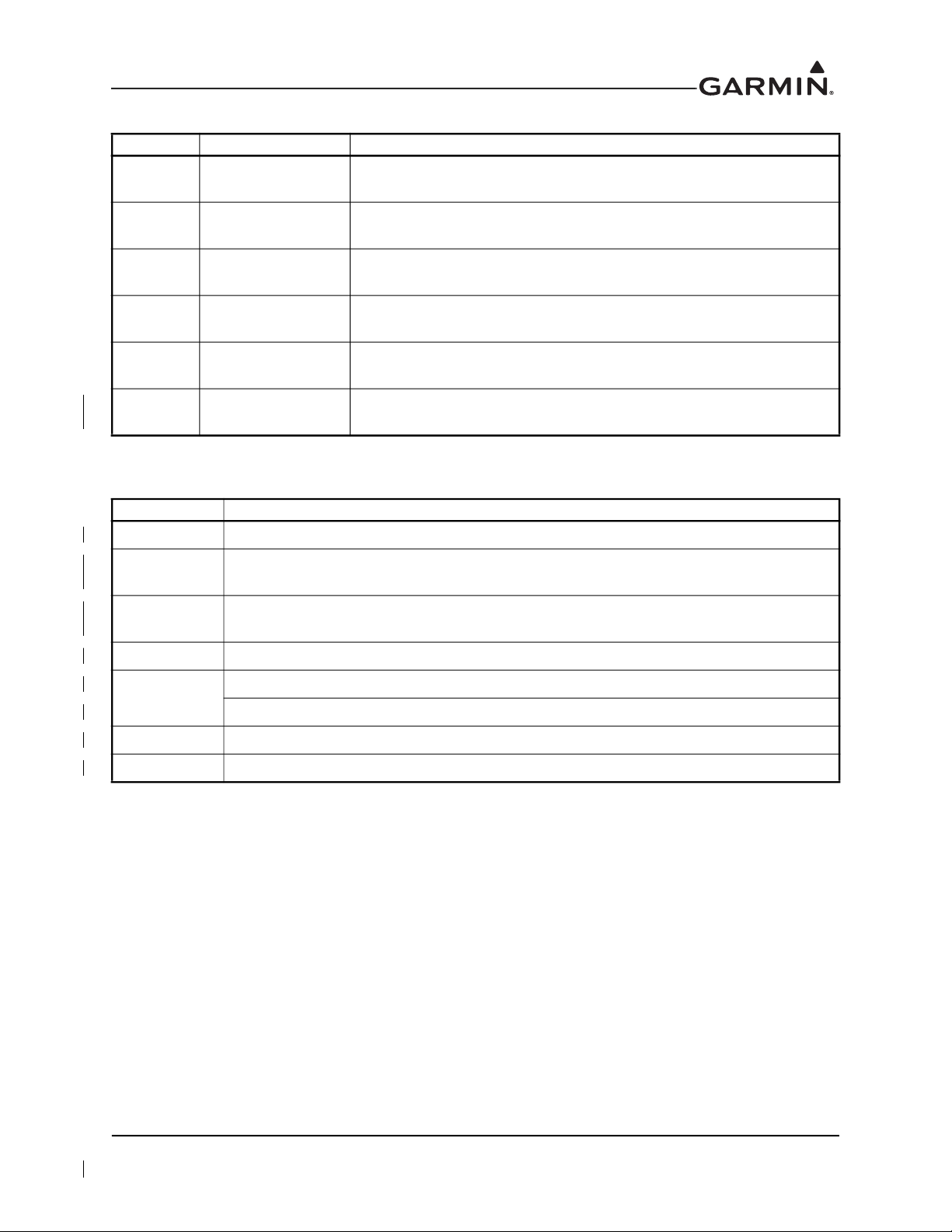
RECORD OF REVISIONS
Revision Revision Date Description
7 11/25/14
Revised to incorporate changes associated with GTN main software
version 5.13.
8 2/25/16
9 9/16/16
10 11/02/17
11 8/21/18
12 1/02/20
Revised to incorporate changes associated with GTN main software
version 6.00.
Revised to incorporate changes associated with GTN main software
version 6.21.
Revised to incorporate changes associated with GTN main software
version 6.41
Revised to incorporate changes associated with GTN main software
version 6.50.
Revised to incorporate changes associated with GTN main software
version 6.70.
CURRENT REVISION DESCRIPTION
Section Description of Change
4.1 Updated wording for Airworthiness Limitations to comply with FAA regulations.
4.5.1
4.5.3
4.6.1 Added voltage drop ranges for different diodes.
Changed the GTN resistance requirement to 5 mΩ for metallic and tube-and-fabric
aircraft.
Changed the GMA 35 resistance requirement to 5 mΩ for metallic and tube-and-fabric
aircraft.
5.3.1.1
6.13 Corrected bonding requirement for Flight Stream 210 bonding strap replacement.
Appendix A Updated Configuration Log to include all configuration settings in software v6.70.
Corrected connector number for COM Power pin.
Corrected “COM remote frequency increment switch” to “COM remote transfer switch”.
190-01007-A1 System Maintenance Manual GTN 6XX/7XX Part 23 AML STC
Rev. 12 Page B
INFORMATION SUBJECT TO EXPORT CONTROL LAWS
This document may contain information that is subject to the Export Administration Regulations (EAR)
issued by the United States Department of Commerce (15 Code of Federal Regulations (CFR), Chapter
VII, Subchapter C) and may not be exported, released, or disclosed to foreign nationals inside or outside of
the United States without first obtaining an export license. Include this notice with any reproduced portion
of this document.
The information in this document is subject to change without notice. Visit Garmin’s Dealer Resource
Center for current updates and supplemental information concerning the operation of Garmin products.
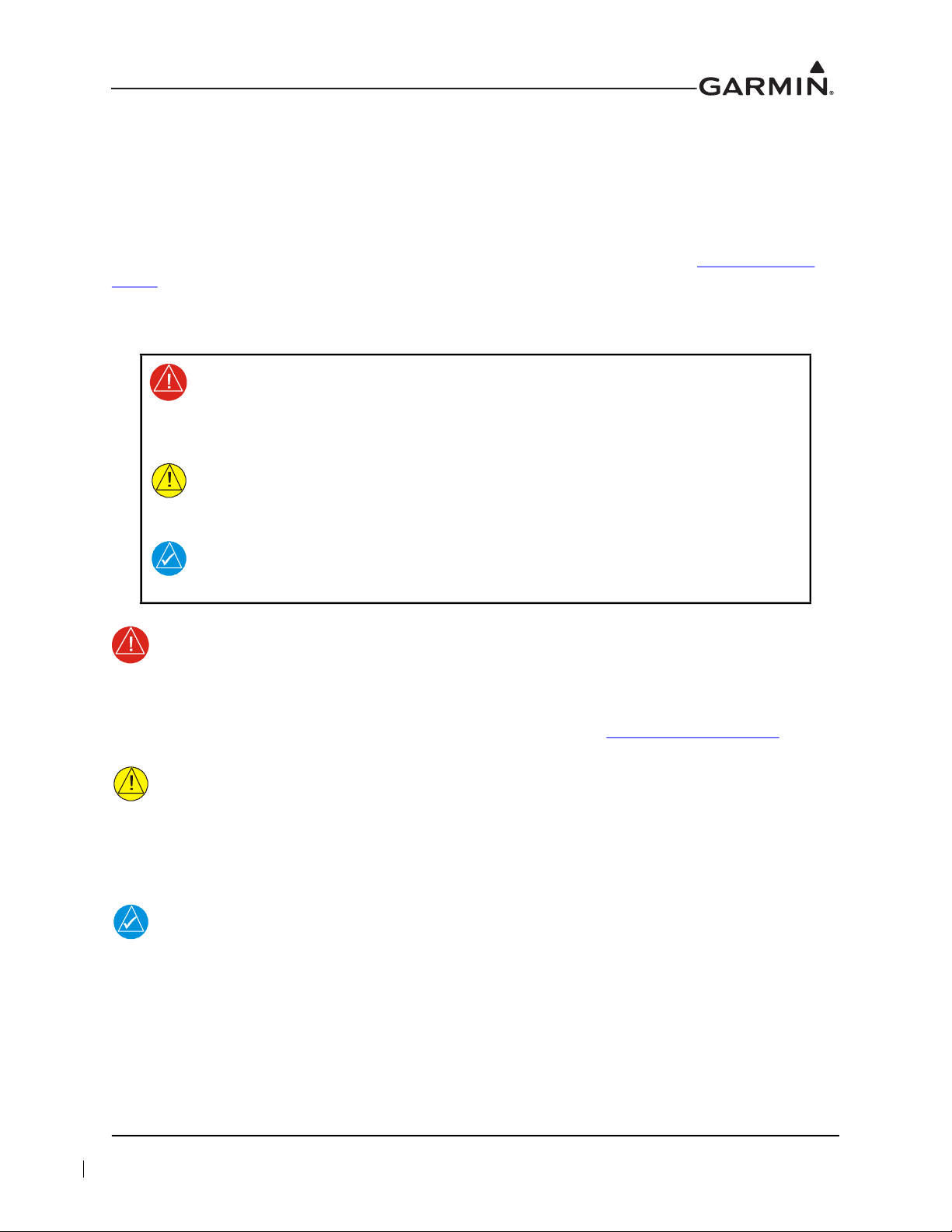
DEFINITIONS OF WARNINGS, CAUTIONS, AND NOTES
WARNING
Warnings indicate that injury or death is possible if the instructions are
disregarded.
CAUTION
Cautions indicate that damage to the equipment is possible.
NOTE
Notes provide additional information.
WARNING
This product, its packaging, and its components contain chemicals known to the State of
California to cause cancer, birth defects, or reproductive harm. This notice is being
provided in accordance with California’s Proposition 65. If you have any questions, or
would like additional information, please refer to our website at www.garmin.com/prop65
CAUTION
GTN 6XX/7XX units have a special anti-reflective coated display that is sensitive to waxes
and abrasive cleaners. CLEANERS CONTAINING AMMONIA WILL HARM THE ANTIREFLECTIVE COATING. It is important to clean the display using a clean, lint-free cloth
with a cleaner that is safe for anti-reflective coatings.
NOTE
All screen shots used in this document are current at the time of publication. Screen shots
are intended to provide visual reference only. All information depicted in screen shots,
including software file names, versions, and part numbers, is subject to change and may
not be up-to-date.
.
190-01007-A1 System Maintenance Manual GTN 6XX/7XX Part 23 AML STC
Rev. 12 Page i

TABLE OF CONTENTS
1 INTRODUCTION..............................................................................................................................1-1
1.1 Content, Scope, and Purpose......................................................................................................1-2
1.2 Organization...............................................................................................................................1-2
1.3 Definitions and Abbreviations ...................................................................................................1-3
1.4 Publications ................................................................................................................................1-4
1.5 Distribution.................................................................................................................................1-4
2 SYSTEM DESCRIPTION.................................................................................................................2-1
2.1 Equipment Descriptions .............................................................................................................2-2
2.2 Backplate Connectors.................................................................................................................2-4
2.3 GTN Optional Interfaces............................................................................................................2-6
2.4 GTN Block Diagram ..................................................................................................................2-7
3 CONTROL AND OPERATION.......................................................................................................3-1
3.1 GTN Normal Mode Overview ...................................................................................................3-2
3.2 Software Loading .......................................................................................................................3-3
3.3 GTN Configuration Mode Overview .........................................................................................3-8
3.4 Database Updates .....................................................................................................................3-20
4 INSTRUCTIONS FOR CONTINUED AIRWORTHINESS.........................................................4-1
4.1 Airworthiness Limitations..........................................................................................................4-2
4.2 Servicing Information ................................................................................................................4-2
4.3 Maintenance Intervals ................................................................................................................4-3
4.4 Visual Inspection........................................................................................................................4-5
4.5 Electrical Bonding Test..............................................................................................................4-6
4.6 Transient Voltage Suppressor (TVS) (If Installed)....................................................................4-9
4.7 GPS/SBAS Antenna Cable Overbraid Inspection (If Installed)...............................................4-11
4.8 WXR HSDB Cable Overbraid Inspection (If Installed)...........................................................4-11
5 TROUBLESHOOTING ....................................................................................................................5-1
5.1 GTN General Troubleshooting...................................................................................................5-2
5.2 GTN Failure Annunciations.......................................................................................................5-6
5.3 GTN System Messages ..............................................................................................................5-7
5.4 Flight Stream Troubleshooting.................................................................................................5-23
5.5 GMA 35 Troubleshooting ........................................................................................................5-25
5.6 GMA 35 Failure Annunciations...............................................................................................5-26
5.7 GMA 35 System Messages ......................................................................................................5-26
6 EQUIPMENT REMOVAL AND RE-INSTALLATION...............................................................6-1
6.1 GTN............................................................................................................................................6-2
6.2 GMA 35......................................................................................................................................6-6
6.3 Data Card/Flight Stream 510......................................................................................................6-9
6.4 Flight Stream 210.....................................................................................................................6-10
6.5 NAV Antenna Cable Diplexer .................................................................................................6-11
6.6 NAV Antenna Cable Splitter....................................................................................................6-11
6.7 Configuration Module (P1001 Only) .......................................................................................6-12
6.8 GTN Fan...................................................................................................................................6-15
6.9 TVS and Fuse (Nonmetallic Aircraft Only).............................................................................6-18
6.10 GPS/SBAS Antenna Cable Overbraid .....................................................................................6-22
6.11 WXR HSDB Cable Overbraid .................................................................................................6-24
6.12 Instrument Panel Bonding Strap ..............................................................................................6-26
190-01007-A1 System Maintenance Manual GTN 6XX/7XX Part 23 AML STC
Rev. 12 Page ii

6.13 Flight Stream 210 Bonding Strap.............................................................................................6-27
7 EQUIPMENT CONFIGURATION AND TESTING.....................................................................7-1
7.1 GTN 6XX/7XX..........................................................................................................................7-2
7.2 GMA 35......................................................................................................................................7-8
7.3 Configuration Module..............................................................................................................7-13
7.4 Interfaced Equipment ...............................................................................................................7-13
7.5 Enabled Features ......................................................................................................................7-26
8 RETURN TO SERVICE PROCEDURE.........................................................................................8-1
8.1 Maintenance Records .................................................................................................................8-1
APPENDIX A AIRCRAFT-SPECIFIC INFORMATION..................................................................A-1
190-01007-A1 System Maintenance Manual GTN 6XX/7XX Part 23 AML STC
Rev. 12 Page iii

LIST OF FIGURES
Figure 2-1 GMA 35 Connector Layout Detail - Rear View ...................................................................2-4
Figure 2-2 GMA 35c Bluetooth Connector Layout Detail - Front View ...............................................2-4
Figure 2-3 GTN 650 Connector Layout Detail - Rear View ..................................................................2-5
Figure 2-4 GTN 750 Connector Layout Detail - Rear View ..................................................................2-5
Figure 2-5 GTN System Interface Diagram ...........................................................................................2-7
Figure 3-1 GTN 6XX Normal Mode Screen ..........................................................................................3-2
Figure 3-2 GTN 7XX Normal Mode Screen ..........................................................................................3-2
Figure 3-3 GTN Software Updater .........................................................................................................3-3
Figure 3-4 System and Software Version ...............................................................................................3-4
Figure 3-5 GTN Software Loader Card Formatting ...............................................................................3-4
Figure 3-6 Update Progress Window .....................................................................................................3-5
Figure 3-7 Update Completion ...............................................................................................................3-5
Figure 3-8 GTN 6XX and GTN 7XX Configuration Mode Pages ........................................................3-8
Figure 3-9 GTN 7XX Updates Page ......................................................................................................3-9
Figure 3-10 System Information Page ....................................................................................................3-10
Figure 3-11 GTN 7XX Setup Pages .......................................................................................................3-11
Figure 3-12 GTN 7XX Options Pages ...................................................................................................3-13
Figure 3-13 GTN 7XX TAWS Configuration Page ...............................................................................3-14
Figure 3-14 Chart Configuration Page ...................................................................................................3-15
Figure 3-15 COM Transmit Power Configuration Page ........................................................................3-15
Figure 3-16 Weather Radar Page ...........................................................................................................3-16
Figure 3-17 Search and Rescue Configuration Page ..............................................................................3-17
Figure 3-18 GTN 6XX and 7XX Diagnostics Pages ..............................................................................3-18
Figure 4-1 TVS Assembly Check .........................................................................................................4-10
Figure 5-1 Failure Screen .......................................................................................................................5-6
Figure 5-2 GMA 35 Failure Annunciation ...........................................................................................5-26
Figure 6-1 GTN 7XX Mounting Rack Assembly ..................................................................................6-3
Figure 6-2 GTN 6XX Mounting Rack Assembly ..................................................................................6-4
Figure 6-3 GMA 35 Mounting Rack Assembly Overview ....................................................................6-7
Figure 6-4 GMA 35c Mounting Rack Assembly Overview ..................................................................6-8
Figure 6-5 Flight Stream Assembly Overview .....................................................................................6-10
Figure 6-6 Backshell Assembly (Potted Configuration Module) .........................................................6-13
Figure 6-7 Backshell Assembly (Configuration Module with Spacer) ................................................6-14
Figure 6-8 Fan/Backplate Orientation (GTN 7XX) .............................................................................6-15
Figure 6-9 Fan Wiring Replacement ....................................................................................................6-17
Figure 6-10 TVS/Fuse Replacement (TVS1/F1) ....................................................................................6-19
Figure 6-11 Detail of TVS Pin Assembly ..............................................................................................6-20
Figure 6-12 TVS2 Assembly ..................................................................................................................6-21
Figure 6-13 GPS/SBAS Antenna Cable Overbraid ................................................................................6-23
Figure 6-14 WXR HSDB Cable Overbraid Details ...............................................................................6-25
Figure 6-15 Instrument Panel Bonding ..................................................................................................6-26
Figure 6-16 Flight Stream Bonding ........................................................................................................6-28
Figure 7-1 Audio Panel Page ..................................................................................................................7-8
Figure 7-2 Main Indicator (Analog) Configuration Page .....................................................................7-13
Figure 7-3 VOR/LOC/GS Configuration Page ....................................................................................7-14
Figure 7-4 XPDR1 Configuration Page ...............................................................................................7-20
Figure 7-5 Audio Configuration Page ..................................................................................................7-26
Figure 7-6 Terrain Configuration Page ................................................................................................7-26
190-01007-A1 System Maintenance Manual GTN 6XX/7XX Part 23 AML STC
Rev. 12 Page iv

LIST OF TABLES
Table 1-1 Recommended Documents ....................................................................................................1-4
Table 3-1 GTN Database Summary .....................................................................................................3-20
Table 4-1 Periodic Maintenance ............................................................................................................4-3
Table 5-1 GTN Troubleshooting Guide .................................................................................................5-2
Table 5-2 Alert Text Troubleshooting Guide ........................................................................................5-7
Table 5-3 COM Alert Troubleshooting Guide ....................................................................................5-11
Table 5-4 GPS/SBAS Alert Troubleshooting Guide ...........................................................................5-13
Table 5-5 VLOC/GS Alert Troubleshooting Guide ............................................................................5-14
Table 5-6 Remote Transponder Alert Troubleshooting Guide ............................................................5-15
Table 5-7 GAD 42 Alert Troubleshooting Guide ................................................................................5-16
Table 5-8 Traffic Alert Troubleshooting Guide ..................................................................................5-16
Table 5-9 Datalink Alert Troubleshooting Guide ................................................................................5-17
Table 5-10 Weather Radar Alert Troubleshooting Guide .....................................................................5-19
Table 5-11 TAWS Alert Troubleshooting Guide ..................................................................................5-20
Table 5-12 Third-Party Sensor Alert Troubleshooting Guide ...............................................................5-21
Table 5-13 Flight Stream Troubleshooting ............................................................................................5-23
Table 5-14 GMA 35 Troubleshooting ...................................................................................................5-25
Table 5-15 Remote Audio Panel Alert Troubleshooting Guide ............................................................5-26
Table 6-1 Self-Test Values ....................................................................................................................6-5
Table 6-2 Configuration Module Wire Color Reference Chart ...........................................................6-12
Table 6-3 Configuration Module Kit P/N 011-00979-03 (P1001) ......................................................6-13
Table 6-4 Configuration Module Kit P/N 011-00979-00 (P1001) ......................................................6-14
Table 6-5 Fan Kit .................................................................................................................................6-16
Table 6-6 Fan Cable Wire Color Reference Chart ..............................................................................6-16
Table 6-7 Instrument Panel Bonding Hardware ..................................................................................6-26
Table 6-8 Flight Stream Bonding Hardware ........................................................................................6-28
Table 7-1 Configuration and Checkout Procedures ...............................................................................7-2
Table 7-2 Summary of COM RX Squelch Settings and Auto Squelch Levels .....................................7-6
Table 7-3 COM Carrier Squelch Selections ..........................................................................................7-6
Table 7-4 COM Carrier Squelch Selections ..........................................................................................7-7
190-01007-A1 System Maintenance Manual GTN 6XX/7XX Part 23 AML STC
Rev. 12 Page v

1 INTRODUCTION
1.1 Content, Scope, and Purpose ............................................................................................................1-2
1.2 Organization......................................................................................................................................1-2
1.3 Definitions and Abbreviations..........................................................................................................1-3
1.4 Publications.......................................................................................................................................1-4
1.5 Distribution .......................................................................................................................................1-4
190-01007-A1 System Maintenance Manual GTN 6XX/7XX Part 23 AML STC
Rev. 12 Page 1-1

1.1 Content, Scope, and Purpose
This document provides Instructions for Continued Airworthiness (ICA) and Maintenance Manual (MM)
for the GTN 6XX/7XX and GMA 35 as installed under STC SA02019SE-D. This document satisfies the
requirements for continued airworthiness, as defined by 14 CFR Part 23.1529 and 14 CFR Part 23
Appendix G. Information in this document is required to maintain the continued airworthiness of the
GTN 6XX/7XX, GMA 35/35c, Flight Stream 210, and Flight Stream 510.
1.2 Organization
The following outline briefly describes the organization of this manual:
Section 2: System Description
Provides a description of the equipment installed by STC SA02019SE-D. An overview of the GTN,
GMA 35, Flight Stream 210, and Flight Stream 510 system interfaces are provided.
Section 3: Control and Operation
Presents basic control and operation information related to maintenance of the GTN 6XX/7XX,
GMA 35/35c, Flight Stream 210, and Flight Stream 510.
Section 4: Instructions for Continued Airworthiness
Provides Instructions for Continued Airworthiness of the GTN, GMA 35, Flight Stream 210, and
Flight Stream 510 systems.
Section 5: Troubleshooting
Provides troubleshooting information to aid in diagnosing and resolving potential problems with the GTN,
GMA 35, Flight Stream 210, and Flight Stream 510 equipment.
Section 6: Equipment Removal and Re-installation
Provides instructions for the removal and re-installation of the GTN, GMA 35, Flight Stream 210, and
Flight Stream 510 equipment.
Section 7: Equipment Configuration and Testing
Provides instructions for configuration and testing of the GTN, GMA 35, Flight Stream 210, and
Flight Stream 510 equipment.
Section 8: Return to Service Procedure
Specifies return to service procedures required after completion of maintenance of the GTN, GMA 35,
Flight Stream 210, and Flight Stream 510 equipment.
Appendix A: Aircraft-Specific Information
Provides a form to record aircraft-specific installation and configuration data for the GTN, GMA 35,
Flight Stream 210, and Flight Stream 510 equipment.
190-01007-A1 System Maintenance Manual GTN 6XX/7XX Part 23 AML STC
Rev. 12 Page 1-2

1.3 Definitions and Abbreviations
Except where specifically noted, references made to the GMA 35 will apply to the GMA 35c.
The following terminology is used within this document:
AC Alternating Current LOI Loss of Integrity
ADS-B Automatic Dependent Surveillance
Broadcast
AGC Automatic Gain Control MHz Mega-Hertz
AGCS Automatic Ground Clutter Suppression NAV Navigation
AHRS Altitude and Heading Reference System OBS Omni Bearing Selector
AML Approved Model List PA Passenger Address
BIT Built-In Test PED Portable Electronic Device
CDI Course Deviation Indicator PTC Push-to-Command
CFR Code of Federal Regulations PTT Push-to-Talk
COM Communications PVT Position, Velocity, Time
CRG Cockpit Reference Guide R/T Radar Transceiver
CSA Conflict Situational Awareness RF Radio Frequency
DME Distance Measuring Equipment RMI Radio Magnetic Indicator
EFIS Electronic Flight Instrument System RX Receive
EHSI Electronic Horizontal Situation Indicator SAR Search and Rescue
FIS-B Flight Information Services Broadcast SBAS Satellite Based Augmentation System
FPGA Field-Programmable Gate Array SDI Source/Destination Identifiers
G/S Glideslope SSM Sign/Status Matrix
GAD Garmin Interface Adapter STC Supplemental Type Certificate
GDL Garmin Datalink TAS Traffic Advisory System
GMA Garmin Audio Panel TCAS Traffic Collision Avoidance System
GNS Garmin Navigation System TAWS Terrain Awareness System
GPS Global Position System TCAD Traffic Collision Avoidance Device
GSR Garmin Services TIS Traffic Information Service
GTN Garmin Touch Navigator TSO Technical Standard Order
GWX Garmin Weather Radar TVS Transient Voltage Suppressor
HSDB High-Speed Data Bus TX Transmit
ICA Instructions for Continued Airworthiness UTC Coordinated Universal Time
ICS Intercom System VDC Volts Direct Current
IFR Instrument Flight Rules VFR Visual Flight Rules
ILS Instrument Landing System VHF Very High Frequency
IRU Inertial Reference Unit VOR VHF Omni-Directional Range
LED Light Emitting Diode WAAS Wide Area Augmentation System
LOC Localizer WXR Weather Radar
LRU Line Replaceable Unit
XPDR Transponder
190-01007-A1 System Maintenance Manual GTN 6XX/7XX Part 23 AML STC
Rev. 12 Page 1-3

1.4 Publications
When performing system maintenance on the GTN, GMA, or Flight Stream, it is recommended that the
following documents be made available:
Table 1-1 Recommended Documents
Garmin Document Part Number
Master Drawing List, GTN 6XX/7XX Part 23 AML STC
Equipment List, GTN 6XX/7XX Part 23 AML STC
GTN 725/750 Pilot’s Guide
Supplemental Airplane Flight Manual for the Garmin GTN 6XX/7XX
GPS/SBAS Navigation System
Supplemental Airplane Flight Manual for the Garmin GTN 6XX/7XX
GPS/SBAS Navigation System (GPS Functions Not Approved for IFR
Navigation)
GTN 6XX/7XX Part 23 AML STC Installation Manual
GTN 6XX/7XX Part 23 Installation Checklist
Guideline for GTN Flight Plan and User Waypoint Files
Notes:
005-00533-C0
005-00533-C1
190-01007-03
190-01007-A2
190-01007-A5
190-01007-A3
190-01007-E1
190-01007-F0 [1]
[1] Contact Garmin technical support for a copy of this document.
1.5 Distribution
This document is required for maintaining the continued airworthiness of the aircraft. When this document
is revised, every page will be revised to indicate current revision level. Garmin Dealers may obtain the
latest revision of this document at the Garmin Dealer Resource
website.
Dealers are notified of manual revision changes via a Garmin Service Bulletin.
Owner/operators may obtain the latest revision of this document at flyGarmin.com
Garmin dealer. Garmin contact information is available at flyGarmin.com
.
or by contacting a
190-01007-A1 System Maintenance Manual GTN 6XX/7XX Part 23 AML STC
Rev. 12 Page 1-4

2 SYSTEM DESCRIPTION
2.1 Equipment Descriptions....................................................................................................................2-2
2.1.1 GTN 6XX/7XX Navigators and GMA 35 .................................................................................2-2
2.1.2 NAV Antenna Cable Splitter......................................................................................................2-3
2.1.3 NAV Antenna Cable Diplexer ...................................................................................................2-3
2.2 Backplate Connectors .......................................................................................................................2-4
2.3 GTN Optional Interfaces ..................................................................................................................2-6
2.4 GTN Block Diagram.........................................................................................................................2-7
190-01007-A1 System Maintenance Manual GTN 6XX/7XX Part 23 AML STC
Rev. 12 Page 2-1

2.1 Equipment Descriptions
2.1.1 GTN 6XX/7XX Navigators and GMA 35
NOTE
For pinouts and wiring diagrams, refer to GTN 6XX/7XX Part 23 AML STC Installation
Manual (P/N 190-01007-A3).
The GTN SBAS navigators are a family of aviation panel-mounted retrofit products. The following
sections will describe the available functions for each unit in the GTN 6XX/7XX navigators.
2.1.1.1 GTN 6XX
The GTN 6XX SBAS navigators are a family of panel-mounted GPS/NAV/COM navigators. “GTN 6XX”
includes the GTN 625, GTN 635, and GTN 650. They are 6.25 inches wide and
2.65 inches tall. The GTN 6XX features a 600 by 266 pixel color LCD touchscreen. The GTN 625 is a
GPS/SBAS unit that meets the requirements of TSO-C146c and may be approved for IFR en route,
terminal, oceanic, non-precision, and precision approach operations when installed in accordance with the
instructions in the manuals referenced in the GTN AML STC. The GTN 635 includes all of the features of
the GTN 625 and an airborne VHF/COM transceiver. The GTN 650 includes all of the features of the
GTN 625, an airborne VHF/COM transceiver, airborne VOR/localizer (LOC) receiver, and glideslope
(G/S) receiver.
2.1.1.2 GTN 7XX
The GTN 7XX SBAS navigators are a family of GPS/NAV/COM aviation panel-mounted products.
“GTN 7XX” includes the GTN 725 and GTN 750. GTN 7XX units are 6.25 inches wide and 6.00 inches
tall. They feature a 600 by 708 pixel color LCD touchscreen. The GTN 725 is a GPS/SBAS unit that meets
the requirements of Technical Standard Order TSO-C146c and may be approved for IFR en route,
terminal, oceanic, non-precision, and precision approach operations when installed in accordance with the
instructions in the manuals referenced in the GTN AML STC. The GTN 750 includes all of the features of
the GTN 725, an airborne VHF communications transceiver, and airborne VOR/localizer (LOC) and
glideslope (G/S) receivers. The GTN 725 and GTN 750 have the ability to remotely control GMA 35 audio
panel functions.
2.1.1.3 GMA 35 Audio Panel
The GMA 35 Audio Panel is a remote-mounted marker beacon receiver and an audio panel with a sixposition intercom system (ICS) that interfaces to the communications and navigation radios, headsets,
microphones, and speakers. The ICS includes electronic cabin noise de-emphasis, two stereo music inputs,
and independent pilot/copilot/passenger volume controls. The intercom provides three selectable isolation
modes. A pilot-selectable cabin speaker output can be used to listen to the selected aircraft radios or to
broadcast PA announcements.
The audio panel relies on the GTN 725 or GTN 750 to control and display the audio functions. The
GMA 35 interfaces to the GTN 7XX through RS-232 for control and display of audio panel functions.
The GMA 35c provides the functionality of the GMA 35, with the capability to pair Bluetooth™ audio
sources. This enables the distribution of audio to ICS positions when using a compatible iOS or Android™
device. The GMA 35c supports up to ten stored devices and one active Bluetooth device.
190-01007-A1 System Maintenance Manual GTN 6XX/7XX Part 23 AML STC
Rev. 12 Page 2-2

2.1.1.4 Flight Stream 210
The Flight Stream 210 interfaces to the GTN 6XX/7XX through RS-232 for attitude information, flight
plan information, and GPS PVT. The information displays on a portable electronic device (PED). The
Flight Stream interfaces to the GDL 88 through RS-422 and the GDL 69 through RS-232.
NOTE
Only one Flight Stream system should be installed per aircraft.
NOTE
Flight Stream supports connection to one navigator at a time.
2.1.1.5 Flight Stream 510
NOTE
The Flight Stream 510 is a wireless-enabled data card that is inserted into the GTN data
card slot.
The Flight Stream 510 interfaces to the GTN 6XX/7XX by replacing the front-loaded data card to allow
wireless database synchronization with PEDs. Synchronized information is then disseminated to various
LRUs through their existing GTN interface connections.
2.1.2 NAV Antenna Cable Splitter
The navigation antenna cable splitter (Garmin P/N 013-00112-00) is used for installations involving dual
VHF navigation capable GTNs or a single VHF navigation capable GTN installation with a second
non-Garmin aviation unit.
2.1.3 NAV Antenna Cable Diplexer
GTN 650/750 navigation units have a single navigation antenna port and require a composite signal for
installations that include separate VOR/LOC and G/S antennas. The navigation diplexer (Comant diplexer
VOR/GS, Model CI-507) is used for these installations.
190-01007-A1 System Maintenance Manual GTN 6XX/7XX Part 23 AML STC
Rev. 12 Page 2-3
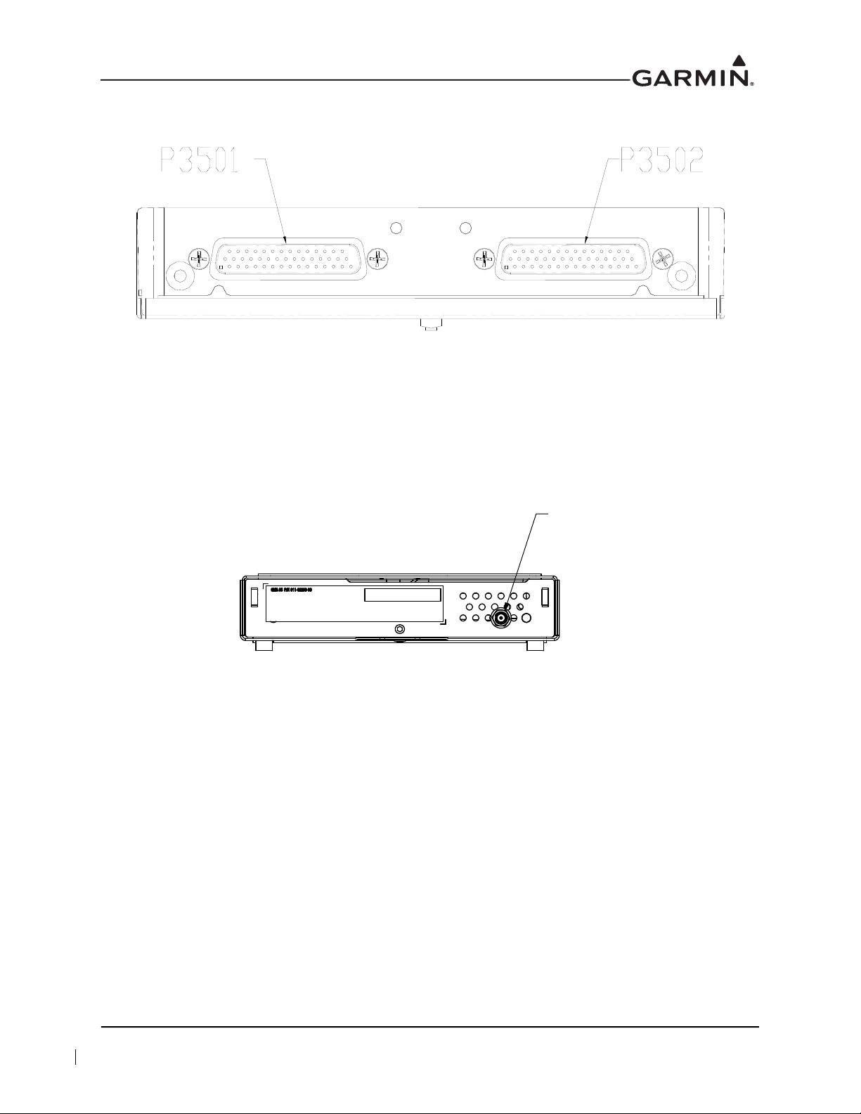
2.2 Backplate Connectors
J3504
GMA35c ONLY
FRONT OF UNIT
Figure 2-1 GMA 35 Connector Layout Detail - Rear View
Figure 2-2 GMA 35c Bluetooth Connector Layout Detail - Front View
190-01007-A1 System Maintenance Manual GTN 6XX/7XX Part 23 AML STC
Rev. 12 Page 2-4
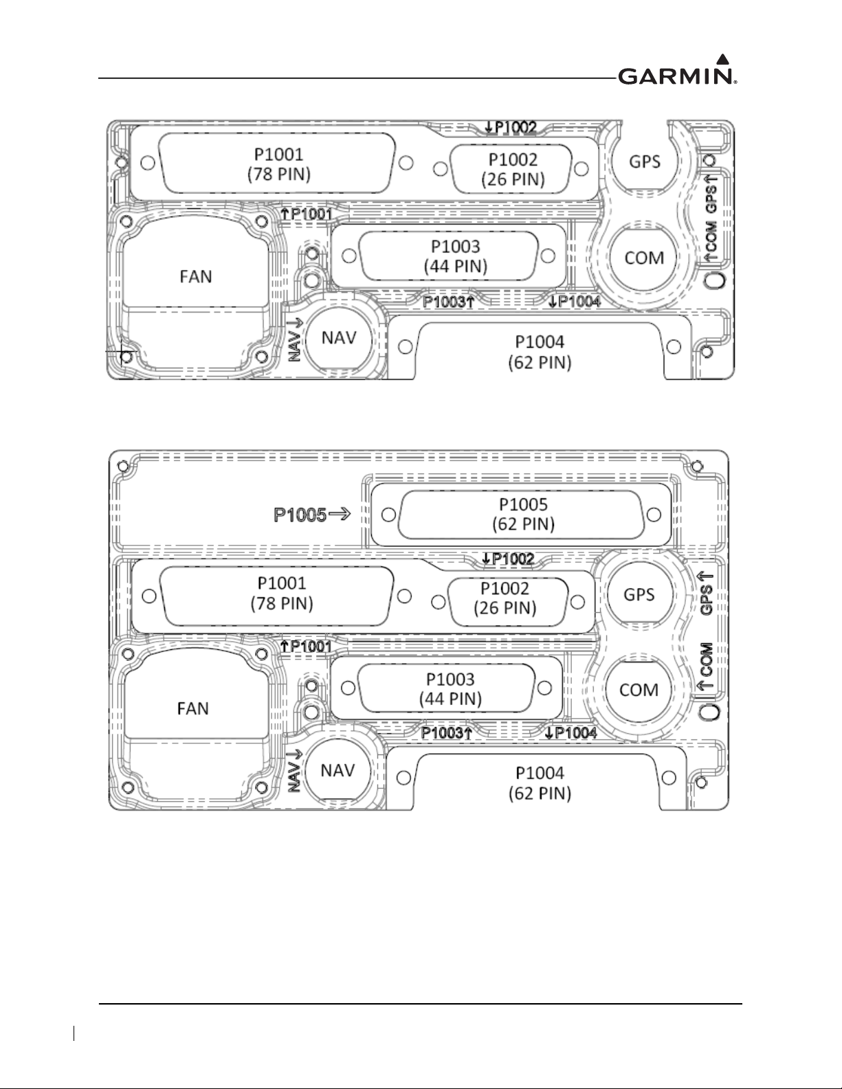
Figure 2-3 GTN 650 Connector Layout Detail - Rear View
Figure 2-4 GTN 750 Connector Layout Detail - Rear View
190-01007-A1 System Maintenance Manual GTN 6XX/7XX Part 23 AML STC
Rev. 12 Page 2-5

2.3 GTN Optional Interfaces
Optional equipment interfaces include:
Audio panel
Air data computer
Altitude serializer or fuel/air data computers
Autopilot
EFIS displays
EHSI displays
IRU/AHRS
Navigation indicators
Weather, traffic, terrain systems
DME
CDI/HSI source selection annunciators
TAWS annunciator panels
Multifunction displays
Interface adapters
Synchro heading sources
Weather radar
Garmin Iridium transceiver
Garmin ADS-B traffic and FIS-B weather sources
Garmin Flight Stream
190-01007-A1 System Maintenance Manual GTN 6XX/7XX Part 23 AML STC
Rev. 12 Page 2-6
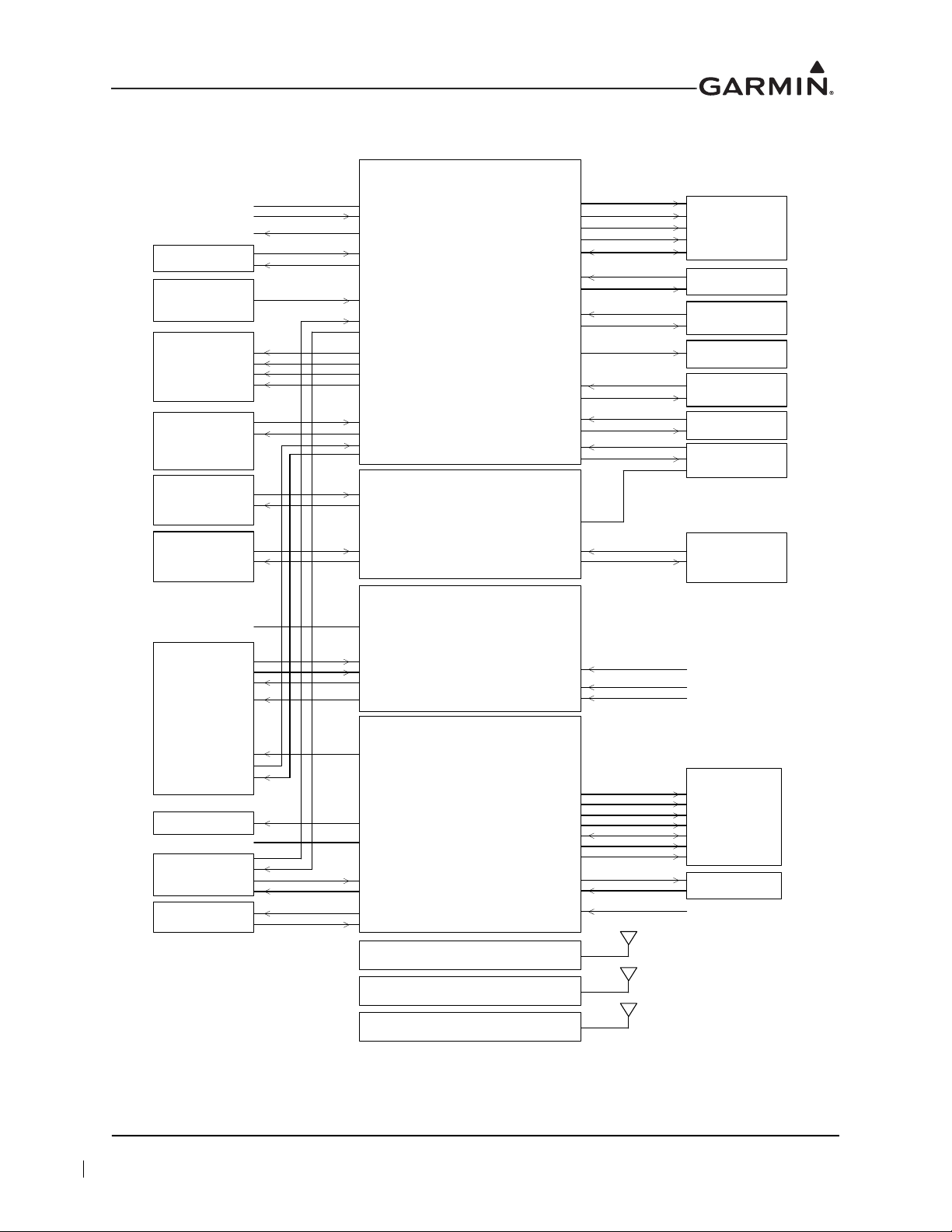
2.4 GTN Block Diagram
GTN 6XX/7XX
CONNECTOR P1001
POWER & GROUND
MAIN CDI/HSI
(GPS/VOR/ILS)
SWITCHES/
ANNUNCIATORS
EXTERNAL MAP
DISPLAY
CDI/HSI
(VOR/ILS ONLY)
KING SERIAL
TUNED DME
PARALLEL TUNED
DME
ARINC 429
EFIS/EHSI
RMI
AUDIO PANEL
FLIGHT CONTROL
SYSTEM
FUEL/AIR DATA
OR
SERIALIZER
GARMIN
GTN 6XX/7XX
(CROSSFILL)
LIGHTING BUS
TIME MARK OUT
ETHERNET IN
ETHERNET OUT
RS-232 IN
ARINC 429 IN
ARINC 429 OUT
ILS/GPS APPROACH
LAT DEVIATION & FLAGS
TO/FROM
VERT DEVIATION & FLAGS
SUPERFLAGS
MAIN OBS
SWITCHES
ANNUNCIATORS
RS-232 OUT
EXTERNAL INSTRUMENTATION
AIRCRAFT POWER & GROUND
AIRCRAFT LIGHTING BUS
GTN 6XX/7XX
CONNECTOR P1002
COM MIC KEY
COM MIC AUDIO
GTN 635/650/750
CONNECTOR P1003
GTN 650/750
CONNECTOR P1004
COM REMOTE TRANSFER COM REMOTE TRANSFER SWITCH
COM REMOTE TUNE UP
COM REMOTE TUNE
SWITCHES
COM REMOTE TUNE DOWN
COM AUDIO
VLOC AUDIO
POWER & GROUND
AIRCRAFT POWER & GROUND
VOR OBI
NAV ARINC 429 IN
NAV ARINC 429 OUT
POWER & GROUND
AIRCRAFT POWER & GROUND
PARALLEL DME TUNING
NAV DME COMMON
NAV REMOTE TRANSFER
NAV REMOTE TRANSFER SWITCH
LAT DEVIATION & FLAGS
TO/FROM
VERT DEVIATION & FLAGS
SUPERFLAGS
VOR OBS
VLOC COMPOSITE OUT
NAV ILS ENERGIZE
SERIAL DME CLOCK/DATA
DME REQUEST COMMON
GTN 6XX/7XX
CONNECTOR P1006
GPS/SBAS ANTENNA
GTN 635/650/750
CONNECTOR P1007
COM ANTENNA
GTN 650/750
CONNECTOR P1008
NAV ANTENNA
TRAFFIC
ARINC 429 IN
DISCRETES
STORMSCOPE
RS-232 IN
RS-232 OUT
GSR 56
RS-232 IN
RS-232 OUT
GNS 400W/500W
SERIES CROSSFILL
RS-232 IN
RS-232 OUT
ANALOG AUDIO
GARMIN
WEATHER RADAR
ETHERNET IN
ETHERNET OUT
OTHER GARMIN LRUs
ETHERNET IN
ETHERNET OUT
DISCRETES
LAT DEVIATION & FLAGS
VERT DEVIATION & FLAGS
SUPERFLAGS
TRANSPONDER
RS-232 IN
RS-232 OUT
RS-232 IN
RS-232 OUT
(GTN 7XX ONLY)
FLIGHT STREAM
210
RS-232 IN
RS-232 OUT
(GMA 35 ONLY)
190-01007-A1 System Maintenance Manual GTN 6XX/7XX Part 23 AML STC
Rev. 12 Page 2-7
Figure 2-5 GTN System Interface Diagram

3 CONTROL AND OPERATION
3.1 GTN Normal Mode Overview..........................................................................................................3-2
3.2 Software Loading..............................................................................................................................3-3
3.2.1 GTN Software Loader Card Creation ........................................................................................3-3
3.2.2 GMA 35 Boot Block Loading....................................................................................................3-6
3.2.3 GMA 35 Software Loading........................................................................................................3-7
3.3 GTN Configuration Mode Overview................................................................................................3-8
3.3.1 GTN Software Updates ..............................................................................................................3-9
3.3.2 System Information..................................................................................................................3-10
3.3.3 GTN Setup Page.......................................................................................................................3-11
3.3.4 GTN Options Page ...................................................................................................................3-13
3.3.5 GTN Diagnostics Page.............................................................................................................3-18
3.4 Database Updates............................................................................................................................3-20
190-01007-A1 System Maintenance Manual GTN 6XX/7XX Part 23 AML STC
Rev. 12 Page 3-1
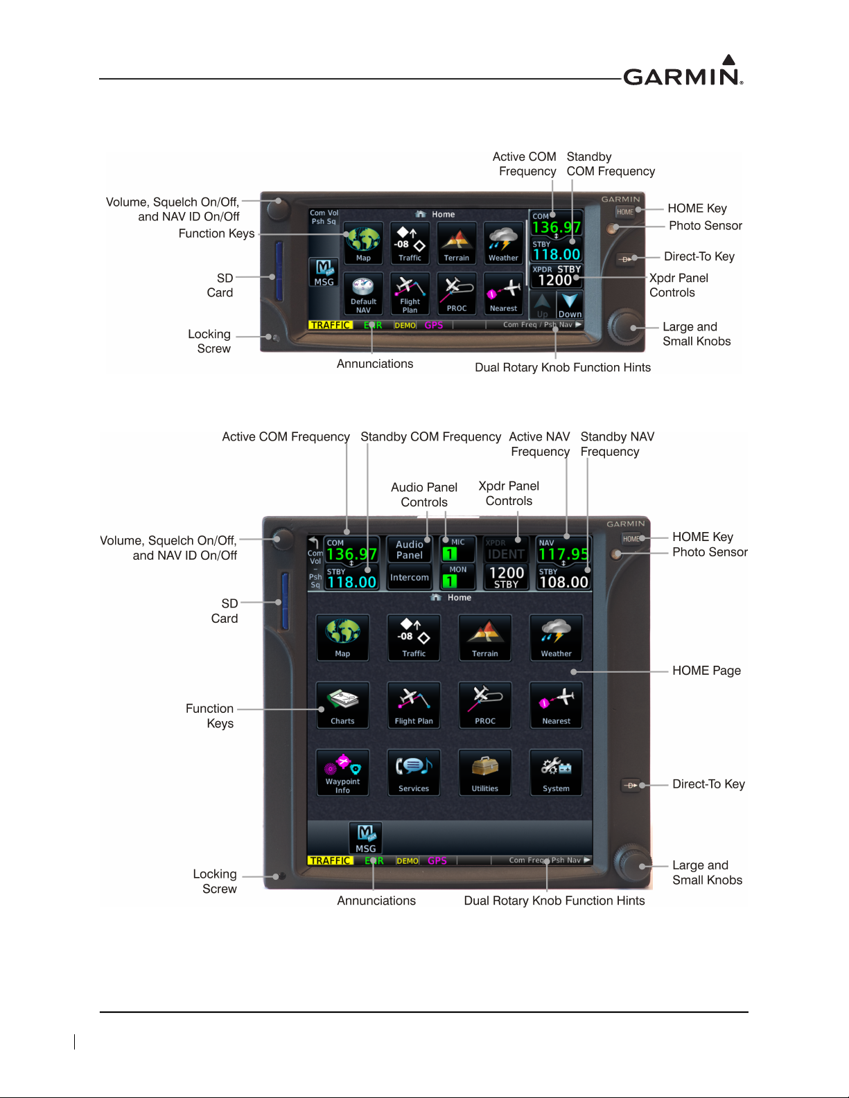
3.1 GTN Normal Mode Overview
Figure 3-1 GTN 6XX Normal Mode Screen
Figure 3-2 GTN 7XX Normal Mode Screen
190-01007-A1 System Maintenance Manual GTN 6XX/7XX Part 23 AML STC
Rev. 12 Page 3-2
3.2 Software Loading
3.2.1 GTN Software Loader Card Creation
CAUTION
In order to create a GTN Software Loader Card, the drive that you select will be
completely erased.
NOTE
The application to create the GTN Software Loader Card performs on PCs with
Windows 2000, XP, Vista, Windows 7, and Windows 10. There is no Macintosh support at
this time.
NOTE
An SD card reader is needed to create the GTN Software Loader Card using the
application that is downloaded from Garmin. The approved readers are SanDisk
SDDR-999 and SDDR-93, although other SD card readers may work.
A GTN Software Loader Card is created using GTN downloadable software and an SD card with a GTN
software application downloaded from the Dealer Resource Center
Resource Center will allow the technician to choose which software package(s) to load onto the card.
Create a GTN Software Loader Card as follows:
1. Go to the Dealer Resource Center
2. Download the GTN Software Loader Image. Refer to Equipment List, GTN 6XX/7XX Part 23 AML
STC for the correct Software Loader Image part number.
3. Ensure that you have an SD card reader connected to the PC. Insert the GTN Downloadable
Software SD Card into the card reader.
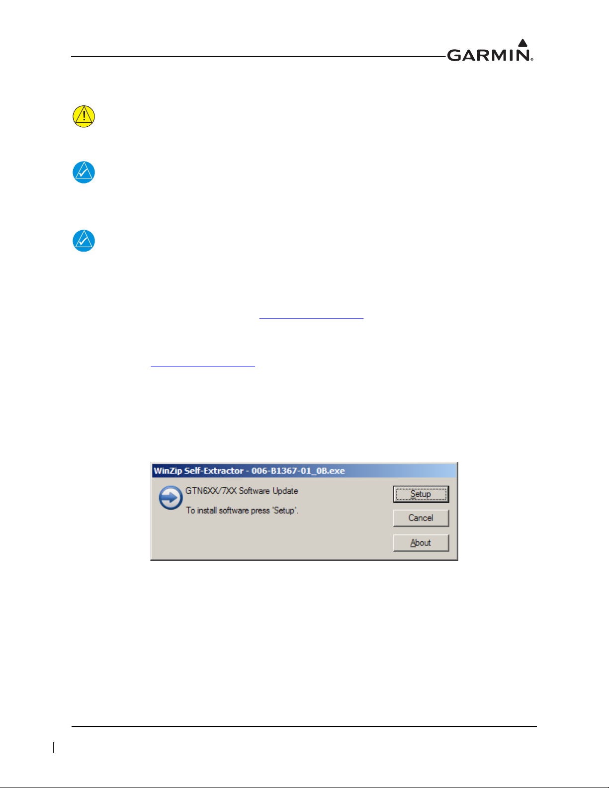
4. Run the executable file.
on Garmin’s website.
on Garmin’s website. The Dealer
®
Figure 3-3 GTN Software Updater
5. Click Setup.
190-01007-A1 System Maintenance Manual GTN 6XX/7XX Part 23 AML STC
Rev. 12 Page 3-3
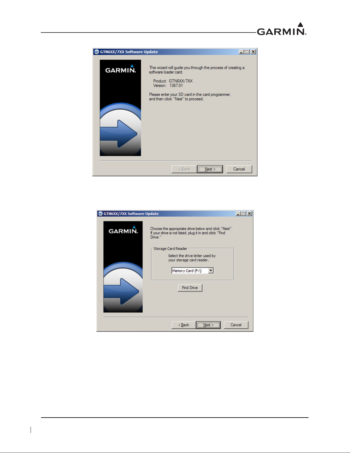
6. Click Next.
Figure 3-4 System and Software Version
Figure 3-5 GTN Software Loader Card Formatting
7. Ensure that the correct drive is selected.
8. Click Next to create the card.
9. Click Next to acknowledge any warnings that may appear.
190-01007-A1 System Maintenance Manual GTN 6XX/7XX Part 23 AML STC
Rev. 12 Page 3-4
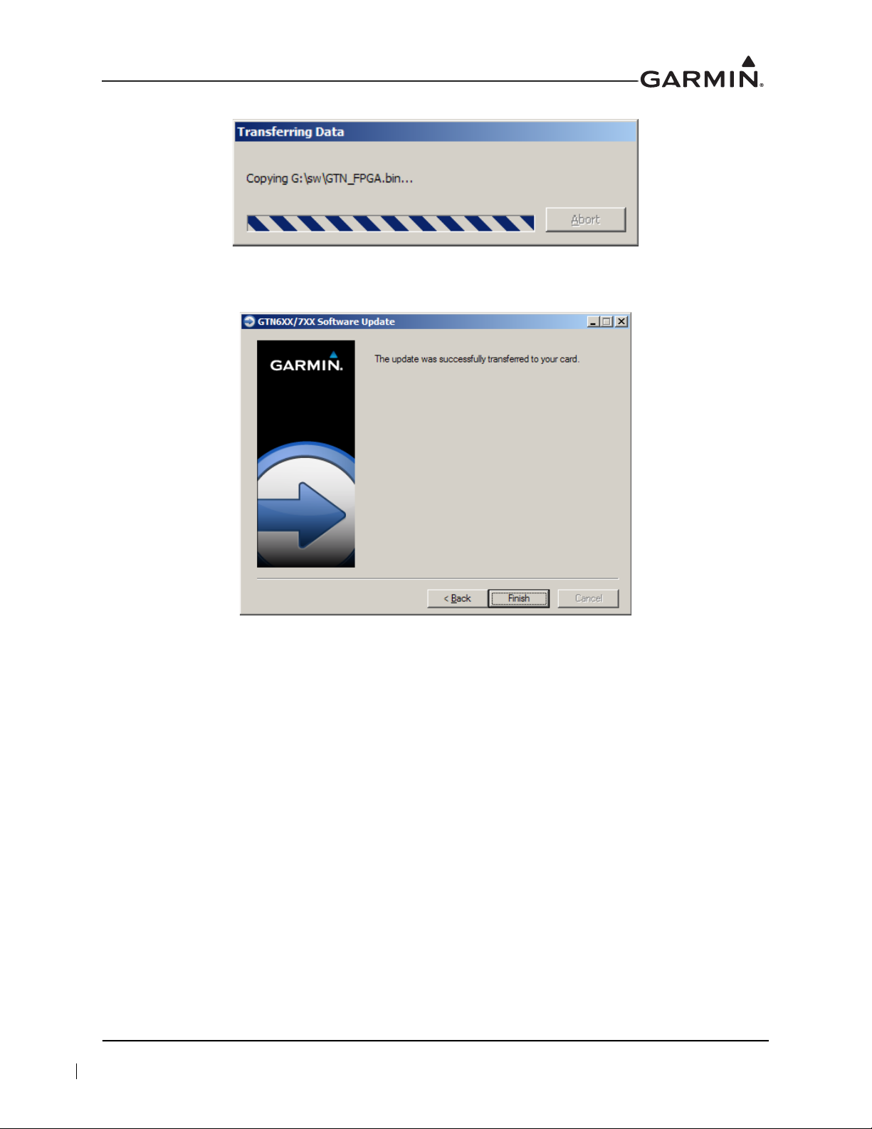
Figure 3-6 Update Progress Window
10. Click Finish to complete the update process.
Figure 3-7 Update Completion
11. Eject the card from the card reader (or stop the card reader in Windows). The GTN Software
Loader Card is now ready to use.
190-01007-A1 System Maintenance Manual GTN 6XX/7XX Part 23 AML STC
Rev. 12 Page 3-5

3.2.2 GMA 35 Boot Block Loading
NOTE
The GMA 35 Boot Block Loader Card is separate from the GMA 35 Software Loader Card
and is required to update Boot Block software to v4.10. For instructions on creating the
GMA 35 Software Loader Card, refer to Section 3.2.3. GTN main software v6.11 (or later)
is required for GMA 35 Boot Block v4.10 (or later).
1. Remove power from the GTN 7XX.
2. Insert the GTN Boot Block Loader Card into the GTN 7XX data card slot. For instructions on how
to create a GTN Boot Block Loader Card, refer to Section 3.2.1.
3. Apply power to the GTN 7XX.
4. Ensure the GMA 35 circuit breaker is closed.
5. Select all GMA 35 Boot Block updates.
6. To begin the software update, touch the Update key on the bottom of the display.
7. The GTN will display the prompt, “Start GMA 35 Software Updates?”
8. To allow the GTN to update the GMA 35, touch OK.
9. When updates complete, the GTN will display, “Update Complete!”
10. Turn the GTN and GMA 35 off by opening the circuit breaker.
11. Remove the Boot Block Loader Card.
12. Re-insert the database card in the data card slot.
13. Restore power on the GTN and GMA 35 by closing the circuit breakers.
14. To ensure the software correctly updated, go to the System Information page and select the
GMA 35. Refer to Section 3.3.2 for more information on the System Information page.
190-01007-A1 System Maintenance Manual GTN 6XX/7XX Part 23 AML STC
Rev. 12 Page 3-6

3.2.3 GMA 35 Software Loading
NOTE
The GMA 35 software will be present on the SD card when creating a GTN Software
Loader Card. A separate card is not required to perform GMA 35 software updates.
1. Remove power from the GTN 7XX by opening the circuit breaker.
2. Insert the GTN Software Loader Card into the GTN 7XX data card slot. For instructions on how to
create a GTN Software Loader Card, refer to Section 3.2.1.
3. Hold down the HOME key until “Garmin” is fully lit on the display after power is applied by
closing the circuit breaker for the GTN 7XX.
4. Ensure the GMA 35 circuit breaker is closed.
5. The Configuration Mode page should now be displayed. Touch the Updates key to display
available software.
6. To select GMA 35 software updates, touch the GTN Software Updates key and select GMA 35
Software Updates.
7. To update the GMA 35 with all available software, touch Select All.
8. Touch the Update key.
9. The GTN will display the prompt, “Start GMA 35 Software Updates?”
10. Touch OK to allow the GTN to update the GMA 35.
11. When the updates are complete, the GTN will display, “Update Complete!”
12. Turn the GTN and GMA 35 off (i.e., open the circuit breaker) and remove the Software Loader
Card.
13. Re-insert the database card in the data card slot.
14. Restore power on the GTN and GMA 35 by closing the circuit breakers and ensure the software
was updated correctly by going to the System Information page and selecting the GMA 35. Refer
to Section 3.3.2 for more information on the System Information page.
190-01007-A1 System Maintenance Manual GTN 6XX/7XX Part 23 AML STC
Rev. 12 Page 3-7
3.3 GTN Configuration Mode Overview
NOTE
When configuring the GTN, ensure that configuration module service messages are not
displayed in the message queue. This indicates an improperly wired or damaged
configuration module.
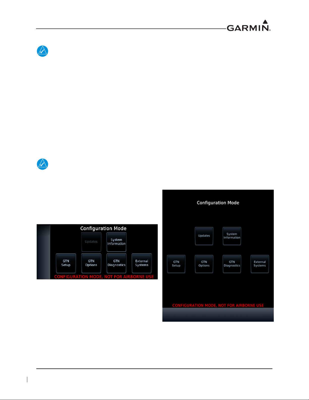
Configuration mode is used to configure the GTN settings for each specific installation. To access
Configuration mode, perform the following steps:
1. Remove power from the GTN by opening the circuit breaker.
2. Press and hold the HOME key and reapply power to the GTN.
3. Release the HOME key when the display activates and “Garmin” appears fully lit on the screen.
The Configuration Mode page is the first page displayed. For detailed information regarding how to
configure the GTN, refer to GTN 6XX/7XX Part 23 AML STC Installation Manual. While in Configuration
mode, select pages by touching the desired key on the display. Some pages may require page scrolling to
view all of the information and keys. Scrolling is done by touching the screen and dragging the page in the
desired direction or by touching the Up or Down keys.
NOTE
The configuration pages shown reflect main software version 3.00. Some differences in
operation may be observed when comparing information in this manual to later software
versions.
Figure 3-8 GTN 6XX and GTN 7XX Configuration Mode Pages
190-01007-A1 System Maintenance Manual GTN 6XX/7XX Part 23 AML STC
Rev. 12 Page 3-8
3.3.1 GTN Software Updates
NOTE
The following steps will need to be repeated for each replacement GTN unit that requires a
software update.
To update the GTN software, perform the following steps:
1. Remove power from the GTN by opening the circuit breaker.
2. Remove the database card and insert the correct GTN Software Loader Card into the data card slot.
Refer to Section 3.2.1 for creating a GTN Software Loader Card.
3. Restore power to the GTN by closing the circuit breaker.
4. The GTN is now in Configuration mode, as shown in Figure 3-8. Touch Updates to display the
available software updates.
5. Check that the software version being loaded to the GTN matches the software version listed in
Equipment List, GTN 6XX/7XX Part 23 AML STC. The Updates page displays the version that is
installed on the unit and the version installed on the loader card.
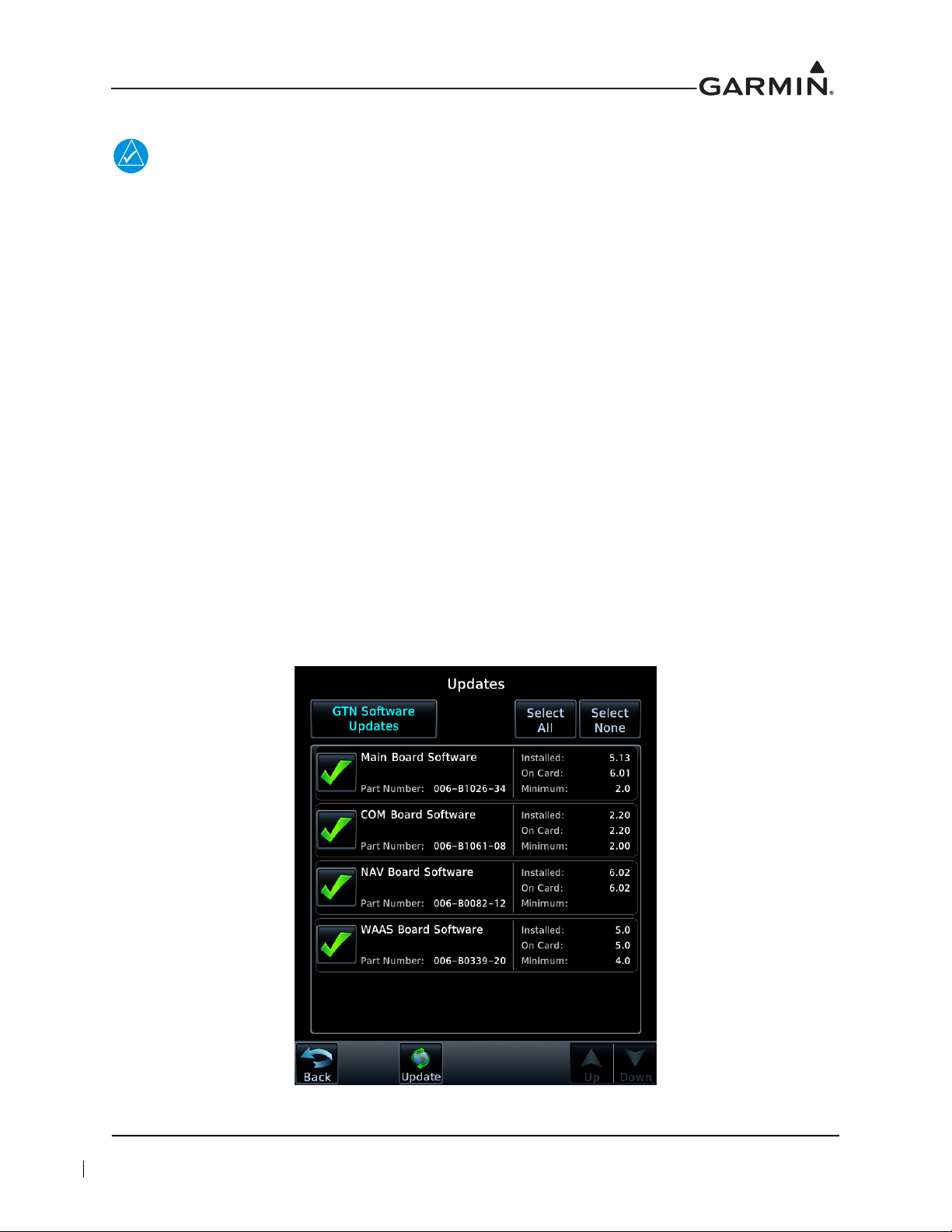
6. Check that the available GTN software updates are displaying by ensuring that GTN Software
Updates key is highlighted in the upper-left corner (upper-right for GTN 6XX) of the display.
7. To update the GTN with all available software, touch Select All.
8. To begin the software update, touch Updates on the bottom of the display.
9. The GTN will display the prompt, “Start GTN Software Updates?”
10. Touch OK to allow the GTN to go through the update process.
11. When the updates are complete, the GTN will display, “Update Complete!”
12. Remove power from the GTN and remove the Software Loader Card. Re-insert the database card
into the data card slot.
Figure 3-9 GTN 7XX Updates Page
190-01007-A1 System Maintenance Manual GTN 6XX/7XX Part 23 AML STC
Rev. 12 Page 3-9
3.3.2 System Information
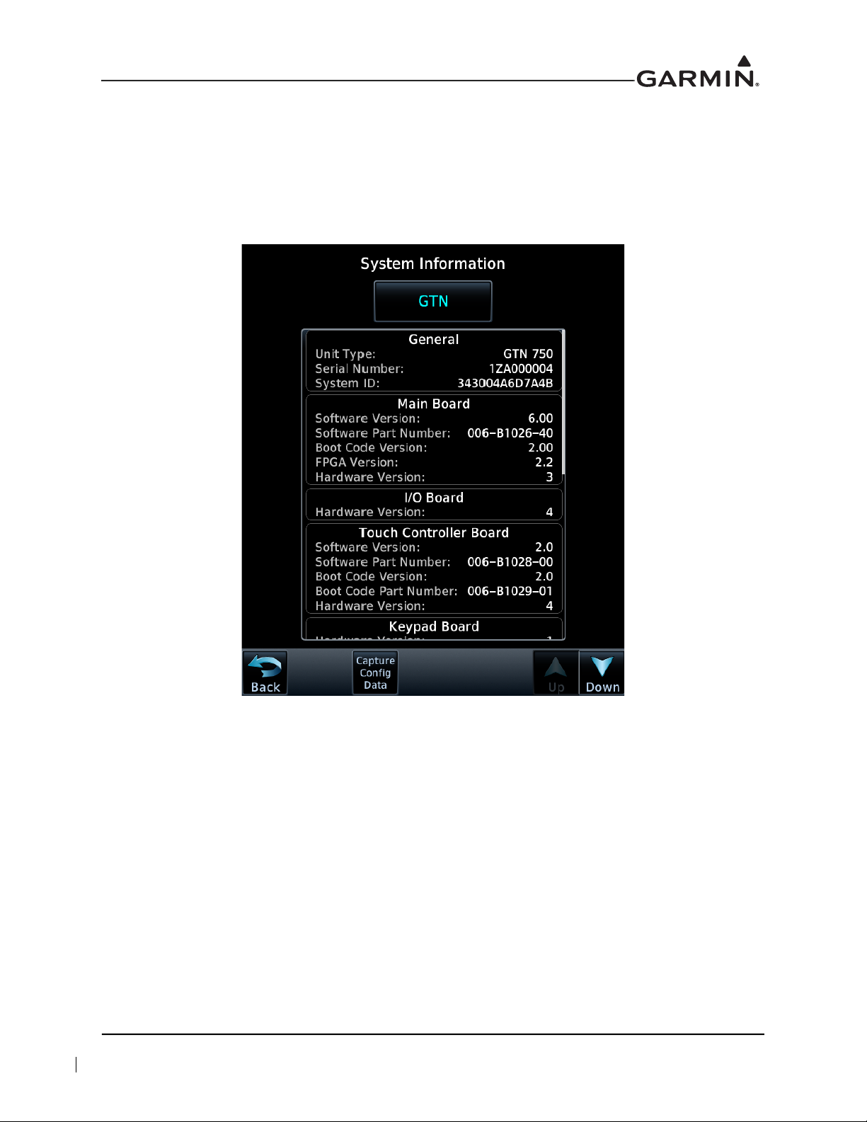
View the System Information page by touching the System Information key on the Configuration Mode
page. The System Information page displays the unit type, serial number, and system ID for the GTN. It
contains the software and hardware versions of the Main, I/O, Display, Keypad, LED, GPS/WAAS, COM,
and NAV boards. System information is available for certain other LRUs connected to the GTN. Touch the
GTN key and choose which LRU to display. Touch UP or DOWN to view all the information.
Figure 3-10 System Information Page
190-01007-A1 System Maintenance Manual GTN 6XX/7XX Part 23 AML STC
Rev. 12 Page 3-10
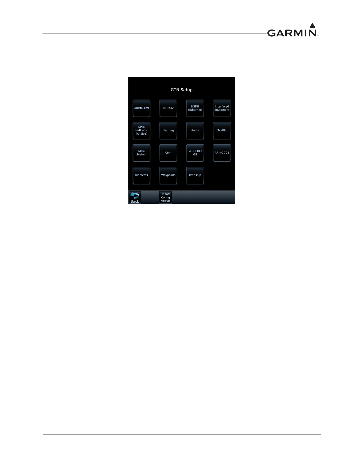
3.3.3 GTN Setup Page
This section provides a brief overview of the pages that are accessed from the GTN Setup page. To access
the GTN Setup page, touch the GTN Setup key from the Configuration Mode page, as shown in
Figure 3-8.
Figure 3-11 GTN 7XX Setup Pages
ARINC 429
This allows the user to configure the ARINC 429 input and output ports on the GTN. Both ARINC 429
formats and bus speeds are set from this configuration page.
RS-232
This allows the user to configure the RS-232 input and output ports on the GTN.
HSDB (Ethernet)
This allows the user to set which Ethernet ports are connected.
Interfaced Equipment
This allows the user to configure which LRUs are installed and interfaced to the GTN. The transponder
selection is automatically configured when a valid transponder configuration is selected on the RS-232
page.
Main Indicator (Analog)
This allows the user to calibrate the OBS resolver and configure the CDI key, selected course for GPS,
VLOC, and the V-Flag state.
Lighting
This allows the user to set the backlight and key lighting brightness display parameters.
190-01007-A1 System Maintenance Manual GTN 6XX/7XX Part 23 AML STC
Rev. 12 Page 3-11
 Loading...