

Page 1
#GflRNIN
Page 2

Page 3

GPS 120
OWNER’S MANUAL
Software Version 2.00 or above
© 1995 GARMIN INTERNATIONAL
9875 Widmer Road, Lenexa, KS 66215, USA
GARMIN/Europe LTD Roben House, Station Approach
Romsey, Hampshire UK S051 8DU
All rights reserved. No part of this manual may be
in any form or by any means, electronic or manual,
and recording, for any purpose without the express
GARMIN.
Information in this document is subject to change without notice. GARMIN
reserves the right to change or improve their products and to make changes in
the content without obligation to notify any person or organization of such
changes or improvements.
May 1995
Part #190-00100AK) Rev. A
Printed in Taiwan.
reproduced or transmitted
including photocopying
written permission of
Page 4

CAUTION
The GPS system is operated by the government of the United States, which is solely responsi
ble for its accuracy and maintenance. The system is subjea to changes which could affea the
accuracy and performance of all GPS equipment. Although the GPS 120 is a precision elearonic
NAVigation AID (NAVAID), any NAVAID can be misused or misinterpreted, and therefore
become unsafe.
Use the GPS 120 at your own risk. To reduce the risk of unsafe operation, carefully revieiv and
understand all aspects of this Owner’s Manual and thorou^ly praaice operation using the simu
lator mode prior to xiuai use. When in actual use, carefully compare mdicattons from the GPS
120 to all available navigation sources including the information from other NAVAlDs, visual
sightings, chans, etc. For safety, always resolve any discrepancies before continuing nav^ation.
NOTE: This device complies with Pan 15 of the FCC limits for Class B digital devices. This
equipment generates, uses, and can radiate radio frequency energy, and if not installed and used
in accordance with the instructions, may cause harmful interference to radio communications.
However, there is no guarantee that interference will not occur in a particular installation. If this
equipment does cause harmful interletence to other equipment, which can be determined by
turning the equipment off and on, the user is encouraged to try and correct the interference by
relocating the equipment or connecting the equipment to a different circuit than the affected
equipment. Consult an auihotiaed dealer or other qualified service technician tor additional help
if these remedies do not correct the problem. Operation is subject to the follovring conditions:
(1) This device may not cause harmful interference, and (2) this device must accept any interfer
ence received, including interference that may cause undtslred operation. The GPS 120 does not
contain any user-serviceable (>ans. Repairs should only be made by an authorieed GARMIN ser
vice center. Unauthorized repairs or modifications could void your wananty and your authority
to operate this device under Part 15 regulations.
Page 5

Preface
Welcome to the easiest-to-use fixed-mount GPS navigator on the water!
The GPS 120 represents GARMIN’s continuing commitment to provide
mariners with quality navigation information in a versatile, accurate and userfriendly design you’ll enjoy for years to come.
To get the most of your new GPS unit, it is important that you take the time
to read through this oYmerk manual to understand the operating features of
the GPS 120. The manual is organized into two sections for your convenience:
Section One introduces you to the basic features of the unit and provides a
quick-start orientation to the GPS 120. It has been designed to acquaint you
with the unit and provide a basic working knowledge necessary to use the unit
in typical conditions.
Section Two provides a detailed reference to the advanced features and
operations of the GPS 120 in a topical format. This allows you to concentrate
on a specific topic quickly, without reading through entire sections of text that
you may not need.
Thanks for choosing the GARMIN GPS 120. If you have any questions or
comments regarding the use of the GPS 120, our Product Support staff is
available to serve you at 1-800-800-1020 or 913-599-1515. You can also
reach our Product Suppon staff by FAX at 913-599-2377.
Page 6

GPS 120 Capabilities
Designed for easy operation, the GARMIN GPS 120 offers powerful features
that make marine navigation as simple and accurate as possible:
Precision Performance
• MultiTracS™ receiver tracks and uses up to 8 satellites simultaneously
for fast, accurate positioning
• Differential-Ready— just add the optional GBR 21 beacon receiver for
5-10 meter accuracy
• Fully gasketed, dry nitrogen-filled case for all-weather use
Advanced Navigating and Plotting
• 250 alphanumeric waypoints
• List of 9 neatest waypoints
• 20 reversible routes of 30 waypoints each
• MOB mode with bearing and distance to mark
• Moving Map Plotting with scales from ,2 to 320 miles (0.5 to 600 km)
• Graphic pages for Satellite Status, Position, Plotting and GDI Navigation
• Active graphic display of cardinal heading
• Alarms for anchor drag, crossttack error and arrival
IV
Page 7

Before getting started with your new GPS receiver, check to see that your
GARMIN GPS 120 package includes the following items. If you are missing
any parts, please see your dealer immediately
Standard Package;
• GPS 120 Receiver with Remote GPS Antenna
• GPS 120 Owner’s Manual
• Quick Reference Card
• Warranty Registration Card
• Mounting Bracket
• Power/Data Cable
Optional Accessories:
• PC Kit
• Swivel Mount Bracket
See your local GARMIN dealer for optional accessories.
Page 8

Page 9

Table of Contents
SEC T IO N O N E G e tt in g S t a rt ed
GPS Overview................................................................................................................. 2
Basic Definitions
Keypad Usage..................................................................................................................... 4
Operation Flowchart........................................................................................................... 5
Power On/Status and Position......................................................................................... 6-7
Page Sequence................................................................................................................... 8
Harking a Position........................................................................................................... 9
Entering a Waypoint
GOTO & Steering Guidance...................................................................................... 11-12
Power Off..................................................................................................................... .....13
SEC T IO N T W O R e fe r en c e
Satellite Status Page.......................................................................................................15-16
Position Page Options
Creating and Using Waypoints.................................................................................. 18-24
GOTOs and MOB Mode........................................................................................... 25-26
Creating and Using Routes......................................................................................... 27-32
Moving Map Plotting.................................................................................................... 33-36
Menu Page and Auxiliary Functions.............................................................................37-47
Simulator Mode............................................................................................................... 48
Appendix A—Installation.............................................................................................49-51
Appendix B—Wiring & Interfaces.....................................................................................52
Appendix C—Glossary..................................................................................................53-54
Appendix D—Messages.................................................................................................. 55
Appendix E—Time Offset..................................................................................................56
Appendix F—Map Datums
Appendix G—Maintenance & Specifications
Appendix H—Index.................................................................................................... 61-62
................................................................................................................
.........................................
...
....................................................................................................
....
........................................................................... 58-59
........
.........................................................
.................................................................
...60
3
10
17
Page 10

What is GPS?
GPS (Global Positioning System) is a satellite-based navigation system developed
by the U. S. Department of Defense to provide a consistent, accurate method of
simplifying navigation. Originally designed for military applications, it also
provides commercial and recreational users with 24-hour, worldwide navigation
coverage with accuracy to 15 meters (49 feet).
How Docs GPS Work?
GPS navigation uses satellite ran^g to determine your position in relation to a
set of satellites orbiting the earth. The GPS constellation is made up of a set of
satellites, which continuously send radio signals containing precise position and
time information for each satellite back to earth.
By knowing the position of any 3 or 4 of these satellites and calculating various
time differences between the transmitted signals, your GPS receiver can determine
its present position anywhere on earth. And once you're under way, your GPS
continuously updates your position and provides speed and track information.
What are the Advantages of GPS Navigation?
For centuries, mariners have been searching for an accurate method of travelling
the world’s waterways. From celestial navigating to loran and SaiNav, each system
has had its problems with weather, range and reliability,
GPS takes navigation to a higher level by providing accurate position and course
information, anywhere in the world, regardless of the weather or your proximity to
land. The accuracy and coverage of GPS navigation can help make your boating
safer, smarter and more efficient wherever you may travel
Page 11

The GPS 120 is a powerful navigation tool that can guide you anywhere in
the world. To better understand its operation and capabilities, it may be help
ful to review the basic terms and concepts briefly explained below,
Navigatian is the process of traveling from one place to another and knowing
where you are in relation to your desired course.
Position is an exact, unique location based on a geographic coordinate system.
Marine navigation is based on the latitude/lon^iude coordinate system.
Meridians of longitude are a set of imaginary circles around the earth that pass
through the north and south poles. Longitude describes position in terms of how
many degrees it is east or west of the Prime Meridian fO" longitude).
Parallcb oflatitude are anotherset of imaginary circles that ate perpendicular
to the earth’s polar axis. Latitude describes position in terms of how many
degrees it is north or south of the equator (0” latitude).
Basic
A waypoint marks an exact position fix so it can be recalled for future use. The
GPS 120 lets you mark waypoints electronically, without physical landmarks.
Bearing is a compass direction to a particular destination (waypoint) from your
present position.
Track is a compass direction representing your course over ground.
Page 12
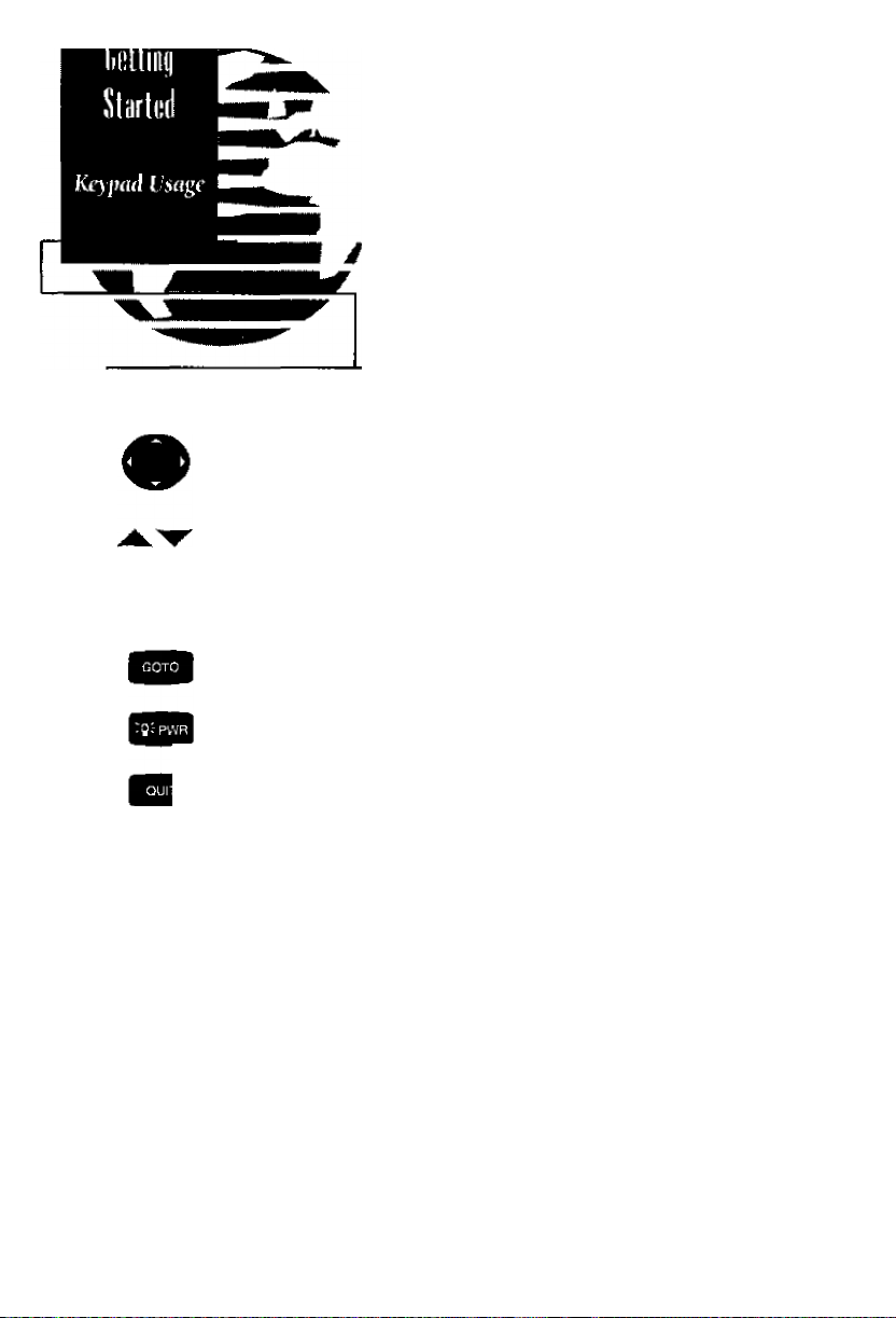
The GPS 120’s two*speed thumbkey allows convenient, one-handed entry
of information. Press on a particular arrow key once to scroll through data
optiotrs slowly, press and hold an arrow key for faster scrolling.
• Use the up and down arrow keys to select alphanumerical characters and
menu choices and to move the field highlight from field to field.
> W 'Use the left and right arrow keys to move the selected character field and
' ^ to move the field highlight from field to field.
The GOTO key changes the display to the Navigation Page with the waypoint field highlighted.
The POWER key turns the unit on and off and adjusts screen backlighting.
To turn the unit off, press and hold the POWER key for 3 seconds.
I The QUIT key returns you to a previous page, or clears data entry, restoring
a data field’s previous value.
The PAGE key scrolls through main data pages in sequence and returns the
display from a submenu page to the previous page viewed. It also displays
the message screen when a message alert appears.
The MARK key captures a position and displays the Mark Position Page.
The ENTER key confirms data entry and on-screen responses. The ENTER
key also activates highlighted fields to allow data entry.
The MOB key performs the man overboard function. This marks the current
position, and always displays your current range and bearing from this posi
tion. The MOB function is listed in detail on page 25.
Page 13
POWER ON
POWER OFF
OpmiiioM
Fhmdiflil
и-ш-
QORnill
QPS1ZO
«ими миг
MARK POSITION
toih*
Гигмм off I» 3
бятт
QPS12C
Hold hey/or
J seconds
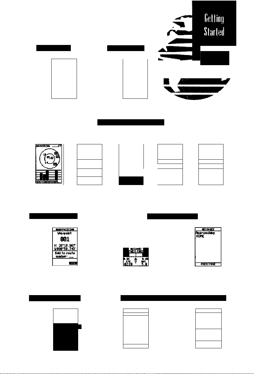
MAIN PAGE SEQUENCE
Press (lie РЛСЕ key ю scroll ill rough poges и sequence.
ЕшЖя
tftK« '^ iWI
%,b\
H
iLtIT«K
t 74^
tliC
Press ihi $[Л7 fciy to scroll through pages in reverse erder.
siFTiaitE «СЯ гм
««PVUWr »11
tiiw
ну
[]35S2fE;
Ш
---------
ВТ
35Г8.19:
35Г s.ev
ТП
------------
ВТ—
305^0.ваг.
306^ а.Гч
ТкК sn
жмГ
Р ~ в
P*S^i lr4S
п
VIEW MESSAGES
ВП1
ПДДКгил
НИ8«1И1
«•mf
HetMC«
•rtMTlfH FETft
IMMUttM ftttr
«cm
Mitmt
tiMc iH Ш1Г
tt* ШИГ
I/* SEW
GO TO WAYPOINT
~m—Щ— um*ut iiiT Mmnf
о №
Ш" "e.e“.
REVIEW WAYPOINT DEFINITION PAGE
ea nrii Vmt
ЯМ1
DOCK
FISM
FUEL
бЙРМЖ
ИОНЕ
JL
П№
itint iLLt^m »CLcm ПЯ
___
►
•MtcDlVE
N 25^0.999*
д97Г95,607'
«meHsiELLS
JtEfi
_____
kEMUM »IStMiet
4T33Sh
итикл
Page 14

%
Welcome to the
QPS1ZO
SOFTUARE UERZ.DD
tOFVFtlCHT 199S
CRRHIII CORP
Welcome Page
HESSMES
Stored Data
uas Lost
Searching the
Sky
The Gelling Slaned Tour assumes you have cor
rectly installed the GPS 120 in your vessel accord
ing to the instructions in Appendix A, and have not
changed any of the factory settings (units of mea
sure, selectable fields, etc ). If you have changed any
of the default settings, ther pictures and descrip
tions used may not match your unit’s configuration.
The first time you power up your new GPS 120 is
an important step in getting the best possible GPS
performance. The receiver must be given an oppor
tunity to collect satellite almanac data and establish
its present position. This process can take 7.5-15
minutes, and is only necessary for first time opera
tion or after memory loss.
You’re now ready to power up and discover the
world of GARMIN GPS navigation.
1. Pressfite^gkevlirmlvto turn the uniton.
The Welcome Page will be displayed while the
unit conducts a self test. Once testing is complete,
the Welcome Page will be replaced by the Status
Page and the unit will begin acquiring satellite data.
Whenever the GPS 120 has something it needs to
tell you, a message indicator box will flash on
screen. To view a GPS 120 message:
1. Press to view the message.
FRESS RAGE
During^rsi iime use,
tfie GPS
120
wtil 'seureft
ihe sfey’ to eslof)lisii
present position. You
may
speed up the int-
tializutioR process
tmrtuaUy
entering jour
position coordinutes
described on page ] 7,
by
your
as
in this case, you will see a ‘Stored Data was Lost,
Searching the Sky’ message. This informs you that
the unit is beginning to acquire satellite information
to calculate your present position.
2. Press to return to the previous screen.
If you’re new to GPS navigation, be sure to review
the GPS Overview and Basic Navigation Terms on
pages 2 and 3 while the unit collects data.
Page 15
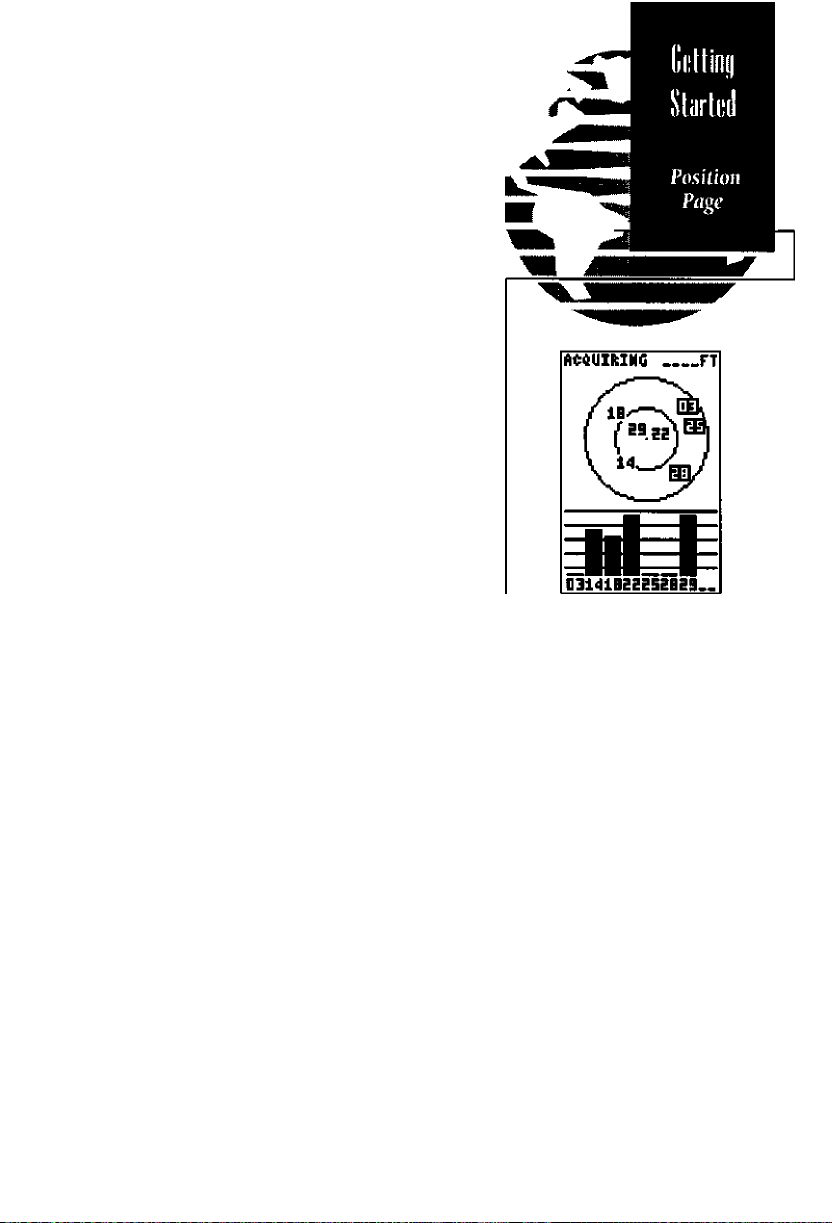
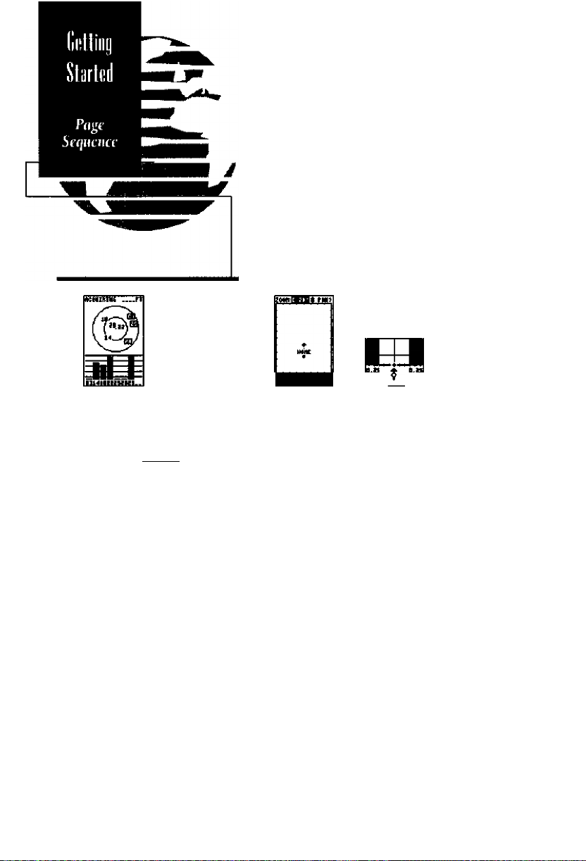
The GPS 120’s Status Page provides a visual refer
ence of satellite acquisition and position. As the
receiver locks onto satellites, a signal strength bar
will appear for each satellite in view, with the appro
priate satellite number (1-32) underneath each bar.
The satellite sky view shows a bird’s eye view of
the position of each satellite relative to the unit’s last
known position. The outer circle represents the
horizon (north up); the inner circle 45” above the
horizon; and the center point directly overhead.
Once sufficient information is received, the Status
Page will be replaced with the Position Page,
The Position Page shows you where you are, what
direction you’re heading and how fast you are
going. The heading display at the top of the page
indicates your cardinal heading (only while you’re
moving) with the track and speed indicated below.
11II11111111II1111III
Grophitat
HcaJinj
Display
3D »5 H DIS D3
TliA«K
1^000^
Speid
8.0“t
POSITION
Track
N 38^53.547'
W094”^I0.477'
■ Position
ALTITUDE
Ahitude
Vl237fT i 74^
TIHE
10:^2:00
Timt
The rest of the page shows your current position
in three dimensions: latitude, longitude and alti
tude. The GPS 120 uses this basic information to
mark exact positions as waypoints, which help
guide you from one place to another
The numbers to the right of the altitude field give
a relative range for the accuracy of the altitude dis
played. GPS altitude without differential correction
is not as accurate as horizontal position, and
fluctuations in this value are normal.
The Status Page's
view will help
<kt ermine ij a
signal is being
by an
abstruciion. As
satellites are
to, the sky
tors will change/rom a
reverse-video
fe.g. satellites 3 6*25)
to
a standard
(e,g, satellites J86* H).
sfey
you
sorellite
blocked
locked on
view indica
highlight
display
Page 16
Getting to know your new GPS requires only a
few short keystrokes. Try scrolling through the
main pages of the GPS 120:
1, Press the key to scroll through the five main
pages in sequence.
2. Press the key to scroll through pages In the
opposite direction.
"IB i?f
sra^e.esb
3BT 8.№
PMiriM
N 35*53,54T
W 594*45,47T
ALTTTUK
tzm t 7Ah
10:42«5
----
TUt SP»
mFE
0,tL,
KffHCf
«rmnfiHiw
nvMmq itnr
MjHf snv
Mr Jtltr
___
Ux (he Page and Quii keys io cmtinuoudv scroil through ifee main pages in either direitm.
Z00n:[ 1* PflNi
+
HOKE
PKG__DST
TRKa43'SPD Z.4KT
The
map page also
displays your currenj
speed and coune, as
well os the bearing and
distance to a selected
destination at the bot
tom of the page.
Map
Page
____
Hit
Since we’ve already gone throught the Status and
Position Pages, let’s move on to a brief overview of
the Map, Navigation and Menu pages.
The Map Page provides a moving map track plot
ter which shows your present position {the diamond
in the center), a visual track log of your past move
ment and nearby waypoints. The Map Page also
allows you to zoom and pn simultaneously to other
areas, mark new waypoints and quickly review on
screen waypoints. Instructions on zooming, pan
ning, and using the map pge begin on page 34.
The Nav Page provides all of the necessary infor
mation to navigate to a destination. Bearing, track,
speed, distance, estimated time enroute (ETE) and
velocity made good are all displayed on the Nav
Page. This information is accompanied by a graphi
cal steering arrow and highway which you may use
to navigate to your destination.
Page 17

The Menu Page contains prompts to perform many
different functions on the GPS 120, including waypoints, routes, alarms, and all setup operations.
Now that you are familiar with the basic pages of
the GPS 120, let’s mark your current position as a
waypoint for future reference. Before you mark your
position, make sure the GPS 120 has acquired
satellite information, and is displaying your current
position and navigation information.
HARK POSITION
Uct^point:
1. Press the key to capture and hold your
present position.
The Mark Position Page will appear, showing the
captured position and a default 3-digit waypoint
name. Let’s change the default name to something
that’s a little more meaningful.
1. Press the key twice lor once) to move the
field highlight from the 'save' field to the name field.
2. Press the Ql key to begin entry of your waypoint
name (Press i to clear pre-existing name).
3. Press and hold die ^ key to scroll through the
alphabet until the letter 'H' appears.
4. Press the ^ key once to move the character high
light to the next character space.
5. Repeat steps 3 and 4 until the word 'HOME'
is displayed.
6. Press to complete entry of the name.
7. Press the key once to return the field highlight
to the'save'field.
OBI
N 38*53.5^7'
W084N0.-i|77'
Rdd io route
number:
HARK POSITIOH
Uaypoint:
N 38*53.547'
W09‘i*40.‘177'
Add to route
number:
HARK POSITIOH
lifciypoiht:
___
___
SAUE4
8. Press the m key to confirm that you want to
save the position as a waypoint named 'HOME'.
The Mark Position Page will be replaced by the
page displayed prior to pressing the ^B
HOME
N 38*53.547'
W094*40.477'
Add to route
number:
___
Page 18

Wtnpoiiil
Now that you’ve marked your present position, it’s
time to enter a new waypoint manually so we may
navigate toward it. This will allow you to go directly
to this new destination quickly and easily. We can do
this one of two ways; either by exaa position coordi
nates, or by referencing a known location.
1. Press or BButitil the Menu Page is displayed.
HENU
KEMEST WTS
UñVrUHT LIST
UiiVf-OIMT
ROUTES
DIS AND SUN OALO
HESSAGES
OF^EAATIDH SETUP
HAUIGATIOH SETUP
ALARMS SETUP
TAAOK LOG SETUP
HAP SETUP
lyO
SETUP
Menu Pu^e
UAVPOIHT
naheiREEF
N 2^*53.781'
W 045*37.2®
REF!
__________
REARING DISTANOE
000* 0.00R.
REHAKE4
DELETED DOÑEO
A new ivoypoini’s
pusilion can i»e
by
maruiatly
coordinates,
distance
from another waypoint,
or
entering a distance
and
hearingfrom your
present position.
defined
entering
entering a
and
bearing
For this example, you’ll need to know either a
waypoint^ position coordinates, or its distance and
bearing from another known position (e g. ‘HOME’),
1. Press the key to highlightthe 'Waypoinf field
and press IB.
2. Press the ▼ key to highlightthe name field.
3. Press 0 to begin entry of the waypoint name.
4. Usethe ▲and 'Tkeystoenteryourwaypoint
name, using the i and ^ keys to move to the
next character position.
5. Press to confirm the waypoint name. The
position field will now become highlighted, with
the receivers last known position shown.
6. Press B to begin entry of the position, or use
the 'w' arrow to highlight the 'reh' field to create
the waypoint a certain bearing and distance from
your current position.
7. Use the Aand '▼'keys to enter your exact posi
tion or die reference waypoint name (leave blank
to use your current positionl.
8. If entering a range and distance feature, use
and to enter the bearing and distance. Press
SI to calculate a newlaVlon position.
9. Press the key to confirm and save your coor
dinates. The default waypoint comment
(UTC date and time of creation) will appear and the
highlight will move to the 'done field.
10
10. Press the key to return to the Menu Page.
Page 19
Now that we’ve seen how to create a new way-
point, lets navigate to it (rementber, we’ll be navi
gating a direct course line to your destination, so
make sure there isn’t an obstruction in your way):
1.Press the! I key.
2. The Navigation Page will appear with the waypointfield highlighted. Press the -^or '^keys
to scroll through the available waypoints until
the waypoint you just created is displayed.
3. Press the key to confirm that you want to
nawgate to the displayed waypoint
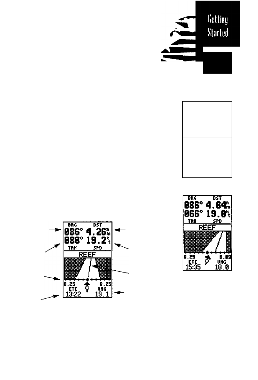
The GPS 120 will now guide you to the waypoint. As you begin moving, the Navigation Page
will display nav data and graphic steering guid
ance, The bearing and distance to waypoint, with
your current track and speed are displayed at the
top of the screen, with your estimated time enroute
(ETE) and velocity made good (VMG, or the rate you
are closing in on your destination) at the bottom.
TRK SPtt
O.ES
ETE
GOTO
StcciiHg
Guidtniœ
35B" "èTS^
ISEE F__
n
n
o tt
,wm
D.ES
UHG
&
Bearing (a
Wa)((wint
Preseti!
Track
Course
Deviation
Scale
Estimated
Time
Enrome
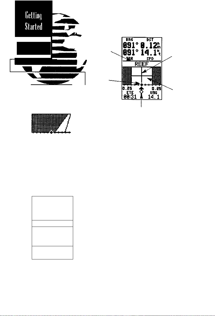
As you head towards your destination, the mid
dle section of the screen provides visual guidance
to your waypoint on a moving graphic ‘highway’.
The moving arrow just below the course deviation
scale always points to your selected waypoint
(REEF) relative to the direction you are moving.
Distance to
Waypoint
Speed
Over
Ground
Grapiiie
Higliway
Vetociiy
Mode Good
The moving highway
provides a visual per-
specliveoj the
and
distance
direction to
waypoint. The highway will
always
move to ‘point’
in the general direction
destination, with
of your
(he relative
indicated
of
the outside lines
the
highway,
distance
by the angle
of
II
Page 20
Giiidiui«’
Bsr 3.^8».
070^ 19.2^
TRK SPD
REEF
D.Ei 4 a.19
ETE y una
11:30 18.^
In this aatnple,
off
the desired
the
left by 0.19
To get hath on course,
steer right to center the
position diamond on the
highway.
№RG UST
09r 3.36^
040^ 19.2^
TRK SP-P
D.ES
ETE^ una
16:33
If you get too far off
course, a message box
will appear to indicate
which
course you
steer
to gel
course most
12
DST
you are
course to
ti.m.
REEF
should
bach
on
ejficientig.
13.3
Destination
Waypoint
Desired
Trach
Line
Position
Indicator
Horiiontol
Finish Line
Pointer to Wajipoini
The line down the middle of the graphic high
way represents your desired track (a straight line
between the position you started from to the
selected waypoint), with your present position
indicated hy the diamond in the center of the
course devition scale. The arrow pointer below the
highway serves as a relative bearing pointer to
your destination waypoint.
As you navigate toward a waypoint, the high
way will actually move, indicating the direction
you’re off course, relative to the position diamond
on the GDI scale. To keep your vessel on the
desired course, simply steer toward the center of
the hi^way.
If you do get off the desired course by more
than l/5th of the selected GDI range, the exact
distance you are off course will be displayed where
the GDI scale setting normally appears (see the
example at left). As you approach a waypoint, a
horizontal ‘finish line’ will move toward the bot
tom of the highway. When the finish line reaches
the GDI scale, you’ve arrived at your destination.
Page 21

You’ve now gone through the basic operation
of your new GPS and probably know a little more
than you think about how it works. We encourage
you to experiment with the GPS 120 until it
becomes an extension of your own marine
navigation skills.
The GPS 120 also features a Simulator mode to
help you practice navigation, mark and save waypoints, and to create and travel routes.
If you encounter any problems using the unit or
want to take advantage of the GPS 120’s advanced
features, refer to the reference section of this manual.
To turn the GPS 120 off:
1. Press and hold the key for 3 seconds.
Thank you for choosing the GARMIN GPS 120.
We hope that it will be a valuable navigation tool
for you, wherever your course may take you.
GPS IZO
SOFTUARC VEke.DD
COPYRIGHT 1995
CARHIH CGRR
The power ojf count-
down
appears right on
screen while you hold
fhi power button. This
counItWn helps pre
vent acddental shutoff
and
toss
of data.
13
Page 22

14
Page 23

5biittí
Signal
Stringili
fndííalors
HofízonlíiJ
/>,ctutaq/
SalílliteSty
Vifw
SaUÜiU Not
Currently
Tracked
Soíeíliíí lumbers
(i-32)
The GPS 120 Status Page displays the status of
various receiver funrtions. The status information
will help you understand what the GPS is doing at
any given time.
The sky view and signal strength bars give you
an indication of what satellites are visible to the
receiver, whether or not they are being tracked,
and the signal quality. When a satellite is visible
but not being tracked, the signal strength bar will
remain blank and the sky view indicator will
remain highlighted in reverse video.
Receiver status is indiated at the top left of
the screen, with the current horizontal accuracy
(in feet or meters) at the top right. The status will
show one of the following conditions:
Acquiring Satellites is the first status you’ll see
in normal operation. The GPS 120 is looking for
satellites to track based on its last known position.
2D Navigation status indicates that at least
three satellites with good geometry have been
locked onto and a 2 dimensional position fix
(latitude and longitude) is being calculated. '2D
DifT will appear when you are receiving DGPS
corrections in 2D mode.
Hie satellite sliy view
ilwws a bird’s eye view
ifie peisiiion
relative
lost feitowfi position.
Hie outer circle represents
ifie fiorizon (north up); the
inner circle
horizon;
point a position directly
over your head. Use
shy view to help determine
if
there ore obstructions
shading your reception
satellite signals.
Ifyouarelosingcover-
age or having trouble
acquiring a
(he shy view and signal
strength bars to guide
you
¡station
of each
to the
receiver’s
45“ above the
and
the center
position, use
towards a better
for GPS reception
of
satellite
the
of
15
Page 24

3D Navigation indicates that at least bur satel
lites with good geometry have been locked onto
and your position is now being calculated in lat
itude, longitude and altitude, ‘3D Dili’will appear
when you are receiving DGPS corrections in 3D
mode.
Searching the Shy indicates that the GPS 120
is collecting new almanac data or AutoLocate™
mode has been selected {see page 38). This
process can take 7.5 to 15 minutes.
Poor GPS Coverage indicates that the receiver
is no longer tracking enough satellites to provide
a 2D or 3D position fix.
Simulator indicates that the receiver is in
simulator mode.
Not Usable indicates that the receiver is
unusable, possibly due to incorrect initialization
or abnormal satellite conditions. Turn the unit
off and back on.
On the right side of the screen, just below the
horizontal accuracy field is the screen backlight
indicator. When backlighting is on, a bulb icon
will appear. To adjust the screen backlighting:
1. Momentarily press the key to toggle
through low, medium, high and off.
16
2. To adjust the duration of screen backlighting,
refer to the operation setup section (page 39).
A
The GPS 120 uses the latesttechnology in ElectroLuminescent (EU tiacklight to provide the most
sistent backlighting possible. The typical life of the
EL backlight at full brightness is 4000 to SOOO hours
of
continuous use.
possible, or not using bacldight when possible wll
extend the life
of the
Using the lowest backlight level
backlighting by many years
eon-
Page 25

The GPS 120 Position Page displays your current
position^ latitude, longitude, altitude and time
numerically. It also displays your track (compass
direction) and speed when you’re moving.
The Position Page also lets you enter a position’s
btitude and longitude manually. During satellite
acquisition, the position displayed is the last com
puted position stored in memory If the receiver’s
position has moved several hundred miles with the
power off or memory has been lost due to battery
failure, the unit may take 7 1/2 to 15 minutes to
acquire satellite data.
To speed up the acquisition process, you can enter the
coordinates of your present positioa Most maps and
chans show the latitude and Icmgitude of major cities.
(.Pressthe
highlighted.
1
Press 0 to begin entry of your position.
3 Use the ^ and ^ arrow keys to selectthe
character position you want to edit
4. Use the akand '▼'arrowkeys to selectthe
value for each field. All fields must have a value.
5. Press the key to confirm your changes.
key until the position field is
|ll M11■111II1111II11
■ 34S ■
TRACK
POSITION
riTTTTJTTTTn
N US D3
■r'uixluiiil
SPEED
e.e’v
N 38*53.547‘
1^09-1*48. W
ALTITUDE
108 l^T i 7^P»
TIRE
15:-47:32
The
utiii
of measure for
speed, position anci alti
tude
are all
user-selec
table. To change the
default
settings Jor these
jields,
refer to
the naviga
tion setup instructions on
paged!.
When the GPS 120 is acquiring satellites or navi
gating in the 2D mode, the last known altitude will
be used to compute your position. If the altitude
shown is off by several hundred feet, you may enter
a corrected altitude manually for greater accuracy.
(.Pressthe
highlighted.
1.
Press to begin entry of your altitude.
3. Use the ▲ and ▼keys to enter a value in each
character field, using the ^ and^ keys
to move to the next character position.
4. Press the key to confirm the altitude.
key until the altitude field is
11111] III I ii 11111 ■ 111|
ID 34S H ois d:
TRACK4SPEED
0.0^
POSITION
N 38*53.850
W094*-18.478'
ALTITUDE
108i
15:<18:11
74^r
TIKE
17
Page 26

Mitiliiiijj
and
N'timijig
Wiijpoittfs
HftRK POSITMH
Wtiypoin-t:
001
N 38*53.547'
W094*40.477*
Add to route
number:
___
Knowing your presenL posiiion is only pan of
any navigation equation. You also need to keep
track of where you’ve been and where you are
going. Waypoints serve as electronic markers that
let you keep track of starting points, destinations,
navaids and any other important position.
The GPS 120 allows you to mark, store and use
up to 250 waypoints. A waypoint position can be
entered by taking an instant electronic fix or by
manually entering a coordinate or range and bear
ing in reference to an existing waypoint. To mark
your present position {make sure you have
acquired a satellite position) as a waypoint;
1. Press the gQ key to capture your position.
The Mark Position Page appears, showing the
captured position and a default 3-digit waypoint
name. To change the default position name :
18
WORK POSITIOW
UuypoiRt:
IS.
N 33*53.547'
W 094*40.477'
Add to route
number:
HRRK FOSniOM
WayDoint:
N 38*53.547'
W094*40.477'
Add to route
number:
___
SftUEi
HOME
___
1. Press the ^ key twice to move the field high
light from the 'save’ field to the name held.
2.
Press the Ql key to begin entry of your waypoint
name (Press 4 to clear a pre-existing name),
3. Use die ▲ and 'r keys to enter a value in the
appropriate character held, using the 4 and ^
keys to move to each character position.
4.
Press confirm the waypoint name. The
field highlight will move to the 'route' field.
If you’d like to add this waypoint to a route:
1. Press the Q key.
2. Use the ^ or ▼ keys to enter a route number.
3. Press the ^ confirm the route number.
4. Press the |Q key again to save the waypoint.
If you do not want to add this waypoint to a route:
1. Move the held highlight to the 'save' held and
press the gn key.
Page 27

The GPS 120 has three waypoint submenu pages
that let you manage a large number of waypoints
quickly and efficiently. The nearest waypoints, way
point list and waypoint definition pages are
accessed through the Menu Page. To select a
waypoint submenu page:
1.Pressthe^9or0
Menu Page appears.
2. Use the .a. and '▼’keystohighlightthewaypoint submenu page you want to use.
3. Press te display the submenu page.
4. To return to the Menu Page, press the key.
I key until the
The nearest waypoints page shows the nine near
est waypoints that are within 100 nautical miles of
your present position, with the bearing and range
noted for each waypoint. During an emergency or
foul weather, the nearest waypoints page can give
you a quick reference to the closest points of safety
in your area.
The nearest waypoints page will also let you
GO TO a selected waypoint or retrieve a waypoint
definition page right from the list:
1. Use the ▲and keys to highlight a listed
waypoint
2. To select a highlighted nearest waypoint as a
destination, press the key.
NEHUEST HF-TS
UftVfOIKT LIST
ItikVPOIHT
iteuTEs
DIS
AHP
SUN OAL«
HESSACES
ePEAATlOK SETUP
HAUICATieil SETUP
ALARHS SETUP
TRACK LOG SETUP
HAP SETUP
SETUP
1/0
NEAREST UPTS
UAVPHT BRG PIS
DOCK
air D.OD
FUEL 159*5.5U
DIUE as9*la.B
HAP ana*
IB.G
FISH a79‘aa.9
------
—
3. Once the Nawgation Page appears, press the
key to confirm the selected waypoint as
yourdestinafion.
To review the waypoint definition page of a
selected waypoint from the list;
1. Press the I I key.
To return to the nearest waypoint page {when
the ‘done’ field is highlighted):
1. Press the I I key.
NEAREST UPTS
UAVPHT PRG PIS
unriBi
air
n.DD
FUEL 199*5.9D
PIUE a99*
la.B
RAP aaa*19.9
FISH aT9*
— —
aa.9
19
Page 28

Wiiypoiiii Li.si
HftVPOIHT LIST
2^3 EHPTV T USED
DIVE
DOCK
FISH
FUEL
The waypoint list page provides you with a
complete list of all waypoints currently stored in
the GPS 120. The total number of used and free
waypoints is indicated above the waypoint list.
From the waypoint list page, you can GOTO a
selected waypoint, retrieve a waypoint definition
page or delete all user-defined waypoints.
1. Use the aL,and ▼ keys to scroll through the
list and select a waypoint
Z To select a highlighted waypoint as a destina
tion, press the key.
20
HOME
MAP
DELETE ALL HF-TS-?
UAVUIIHT LIST
242 EHPTV 7 USEft
DIVE
DOCK
FISH
FUEL
GARMIN
HOME
MAP
DELETE tiLL
DELETE ALL HPTS
U f T S /
HARKING!
dll user defined
uidviDoints ctnd
routes uill be
deleted
Are you sure
or No?
3. Once the Navigation Page appears, press the
key to confirm the selected waypoint as
yoor destination.
To review the waypoint definition page of a
selected waypoint from the list:
1. Press the I
I key.
To return to the waypoint list page {when the
'done’ field highlighted):
1. Press the key.
To delete all user defined waypoints;
1. Use the .A. or keys to move the cursor high
light to the 'delete all waypoints' field.
2. Press the
I key.
I
A warning page will appear, asking if you are
sure you want to delete all user-defined waypoints
and routes. If you want to continue and delete:
1. Press the ^ key to highlight the 7es' field.
2. Press them key.
3. Press the key to return to the Menu Page.
If you do not want to delete all vraypoints:
1. Press with the 'no' field highlighted.
Page 29

The last of the three waypoint management
pages is the waypoint definition page. This page
lets you create new waypoints manually, as well as
review and edit existing waypoints.
Wi^poinl
Nom e
Com m ent
Bdd
Rename
and
Delete
Fields
UflYPOIHT
______
H 25*05.180*
W 077*21.118*
D7-FEB-94 a0:47
REF!
_________
REARIHC DISTANCE
000* 0.00Rs
REHANEY
DELETE? DONE?
^
Position
CooriJinoles
Re/erence
Wo^'poinf
Done Prompt
returns tlie
display to
previous page
To create a new waypoint manually, you’ll need
to know its position coordinates or its distance and
bearing from an existing waypoint. If you know
the position coordinates for your new waypoint:
1. Press the ▼ key to highlight the name field.
2. Press m to begin entry of the waypoint name.
3. Use the -a, and't' keys to enter your waypoint
name, using the i and y keys to move to the
next character position.
4. Press to confirm the waypoint name. The
position field will now become highlighted, with
the receiver's last knovm position shown.
UAVFCIHT
NAIIEiFISH
Wm77-"21. 111?'
REF:
_________
REARING DISTANCE
060* 0.001k
RENAttE?
DELETE?
HAVPCINT
DONE?
NAtlDFISH
Q] 25*05.180'
W077*2i. US'
REF!
__________
REARING DISTANCE
000* 0.00Kv
RENAHE?
DELETE? DONE?
5. Press to begin entry of the position.
6. Use the ▲ and ▼ keys to enter your position,
using the ^ and ^ keys to move to each
character field.
7. Press the key to confirm and save your
coordinates. The default waypoint comment
(UTC date and time of creation} will appear and
the highlight will move to the 'done' field.
8. Press the key to return to the Menu Page.
UAVPOINT
««HE: FISH
N 25*05.180’
W 077*21.118’
REF!
__________
REARING DISTANCE
000* 6.00!k
RENAHE?
DELETE?
21
Page 30

/ií’/t'l Í'ÍIC^
Wfl^/joipiís
To create a new waypoint manually without
knowing its position coordinates, you’ll need to
enter its bearing and distance from an existing waypoint. The GPS 120 will then calculate the position
coordinates for you.
UflVPOIHT
NAME: ANCHOR
N 25*05.180'
W 077*21.118'
OB-FEB-94 DB:S5
REF:|
ÍEARIMC DISTANCE
000* 0.00R.
REHANEi
DELETE)
HAVPMNT
DCHE)
MAME: ANCHOR
M 25*05.180'
W077*21.118’
DB-FED-34 SBiSS
RtrFISH
REARING DISTANCE
260* 05. gR.
RENAME)
DELETE)
DONE)
Waypoint
Name ~
UAVPCINT
NAMEtÑNCHOS
N 25*05.130’
Reference
W 077*21.113'
Waypmnt
REF:
Bearing
from
Reference
Waypoint
1. Press 'w until the name field is highlighted.
2. Press to begin entry of the waypoint name.
3. Enter the name of your new waypoint
4. Press the Q key to confirm the waypoint name.
The position field will now become highlighted,
with the receiver's last known position shown.
5. Press the ▼ keyto move the cursor highlightto
the reference field.
6. Press to begin entry of reference waypoint.
REARING DISTANCE
000*
RENAME)
DELETE)
0.00K.
DONE)
PosiiWfl
' Qwriitnaies
are coioJated
after entering
reference data
Dtsiance
from
Reference
tVaypnmt
22
HAVPCINT
NAME: ANCHOR
N 25*03.63^'
W077*26.934’
DB-FER-94 DB:5S
REF: FISH
REARING DISTANCE
260* 5.50Ü.
RENAME)
DELETE)
T.Usethe a^and '▼'keystoenterthenameof
your reference waypoint using the ^ and^ keys
to move to each character field.
8. Press the keyto confirm your entry.
9. Enter the bearing and distance of your new waypoint from the reference waypoint Remember to
use the Q key to begin entry and confirm each
tield.lTie coordinates will be calculated and saved
for your new waypoint
10. Press the key jwhen the 'done' field is high
lighted} to return to the Menu Page.
Page 31

From the waypoint definition page, you can also
review and change any stored waypoint’s name,
position coordinates, comment field or reference
waypoint at any time. The waypoint definition
page is also used to delete individual waypoints.
To change a waypoint’s position coordinates or
reference waypoint:
I. Use the ▲and
you want to edit
2. Press to begin entry in the selected field.
3. Enter your new data.
4. Press the key to confirm your changes.
' keys to highlight the field
Each waypoint stored in the GPS 120 has a userdefined 16 character comment field. The default
comment is the UTC date and time of the way
point’s creation. To change or add a comment:
1, Use the ▲and
comment field.
2. Press to begin entry of your comment
3. Enter your new comment
4. Press the key to confirm your changes.
keys to highlight the
The rename and delete function fields are located
at the bottom of the screen, to the left of the ‘DONE’
prompt. To select one of these functions, you need
to use the ^ key to move the cursor highlight out
of its main scrolling sequence. To rename a stored
waypoint:
1. Usethe^ and^ keystohighlightthe
'rename'field.
2. Press the key to activate the rename page.
3. Enter the new waypoint name and press
4. Press the key to confirm your changes.
HftVkOIHT
Nfltit ANCHOR
N 25*03. G3-C
W 877*26.934'
fAHD-IOTTOQ
______
REF! FISH
REARIHC DISTANCE
260* 5.50R.
REHAHET
DELETED DONEf
HAVPOINT
HAHE: ANCHOR
N 25*03.$3^'
W077*26.93^'
SAND SCTTOn
REF: FISH
DEARIHfi DISTANCE
260* 5.50K.
F;ENAt1E';'
DELETE? DONE?
RENAHE HAVFOINT
From
RNCHDR
To:
RFT-UP
fire you sure
lor Ho?
23
Page 32

!it:nini:t!
Dí’lt’tiiij,'
Wflj|»«ínís
DELETE UAYPDIHT
To delete a stored wa/point:
1. Use the 4 key to move the cursor highlight from
the 'DONE' promptto the 'delete' held.
2.
Press the Q key to activate the delete page.
3. A warning message will appear, asking you to
confirm your deletion.
HARHING!
MfiP
uill be deleted
flre you sure
lor Ho?
4. Pressthe^ keytoselectdie7ES'prompt
5. Press the key to delete the waypoint and
return to the waypoint page.
A
Waypoints that are part oían active or stored
route cannot be deleted. You must tirst go to the
route page and remove the waypoint
routes. See pages 31 and 32 for complete
instructions on editing routes.
from
all
24
Page 33

The GPS 120’s GOTO function lets you choose
any stored waypoint as a destination and quickly set
a course ftom your present position. Once the
GOTO function has been activated, the Navigation
Page will provide you with graphic steering guid
ance to your destination. To activate the GOTO
function:
I. Press the key,
2 The Navigation Page will appear with the way
point field ready to accept changes.
3. Enter your destination waypoint
4. Press the key to confirm that you want to
navigate to the displayed waypoint
You can also quickly activate the GOTO function
from any other page by simply highlighting a waypoint and pressing the ^y key
Another time-saving function of the GPS 120
that you may have noticed when entering waypoint names is the waypoint scanning feature. As
you enter waypoint characters, the screen will
automatically display the first numerical or alpha
betical match of the character you have entered.
This will save you from always entering an entire
waypoint name. To use the scan feature when the
waypoint field is highlighted:
1. Press the i key to clear the nam e field.
2. Use the .a. and '▼'keys to scroll through your
waypoints,
3. If you have more than one waypoint that begins
with the same letter or number, you must use the
^ key to move to die next character positions as
needed. Only the first character match is listed
for each character set.
4. Once you've found the desired waypoint
press m
To cancel an. active
GOTO from any
press
Next,
arrow key, and concern
your cancellation by
pressing the enter hey.
Iliis mII stop
steering guidance along
the original GOTO
desired track
page,
the GOTO key.
press Ifie
continued
leji
25
Page 34

BRG DST
082° 1.3^;:.
081° 18.r
TRK SFP
The GPS 120’s man overboard function (MOB)
lets you simultaneously mark and set a course to a
position for quick response in emergency situa
tions, To activate the MOB mode:
1. Press the key
2. The Navigation Page will appear with the default
GOTO waypoint 'MOB' as the destination.
3. Press the key to confinn the MOB entry.
The Navigation Page will now guide you to the
MOB waypoint position.
SI
o.es + a.as
ETE 9 'inc
0^:27 18.8
Martin^
an MOB
Bearing lo
MOB
Pment
Track
Estimated
rime
Enrcruie
Distance te
Velocity'
Made
The graphic ‘highway’ provides visual steering
guidance to the MOB waypoint. The moving arrow
just below the course deviation scale always points
to your selected waypoint relative to the direction
you are moving.
Your present position is represented by the dia
mond in the center of the course deviation sale.
The line down the middle of the highway is your
desired track. As you head toward a waypoint, the
highway wifi move indiating the direction and
distance you are off course, relative to the position
diamond on the GDI scale. To keep your vessel on
course, steer toward the center of the highway
MOB
Speed
Over
Grpund
Good
26
If you want to save the MOB waypoint, be sure
to rename it, as it will be overwritten the next time
a MOB is executed.
Page 35

The GPS 120’s route navigation feature lets
you plan and navigate a course from one place
to another using a set of pre-detined waypoints.
Routes are often used when it’s not practical, safe
or possible to navigate a direct course to a particu
lar destination.
Routes are broken down and navigated in
smaller segments called legs’. The waypoint you
are going to in a leg is called the ‘active to’ way
point, and the waypoint immediately behind
you is called the ‘active from’ waypoint. The line
between the ‘active to’ and the ‘active from’ waypoint is called the 'active leg’.
‘Active Leg'
Waypoint 1
raertive from'
When you activate a route with the GPS 120, it
will automatically select the route leg closest to
your position as the active leg. As you pass a waypoint in your route, the unit will select the next
waypoint as the ‘active to’ waypoint.
27
Page 36

HARK POSITION
The GPS 120 lets you create and store up to 20
routes of 30 waypoints each. Routes are created,
copied and edited through the route definition
page, which is accessed through the Menu Page,
To select the route definition page:
1. Press imtj] the Menu Page appears.
2.
Use the ak and ▼ keys to highlightthe
'routes' submenu page.
H 38^53.530‘
W 034*48. ^31*
8dd to rout»
number: D
¡J you're headingoul
ifie
water
planned route to
gate, the CP5120 route
feature can
a
helping hand
home.
Create a
points with the morh he;y
and save them to
open
route
Marh Position Page,
When_youareread)’/o
head hoefe to
ply activate the route
you created
order (see page
This method is
useful
unfamiliar waters or you
are simpi)'running out
daylight.
of
28
0B1
wit/iout
stilf
series
from
in
when
navi
provide
of way-
the
port,
inverted
30).
you're
snuEf
on
a
hack
an
sim-
especially
in
3. Press the key to display the routes page.
4. To return to the Menu Page, press
Comment
field
Route
Waypoint
Route
Number
Route Leg
Distance
Seipirnce
Route Action
Fields ■'
, Desired Troclt
o/Leg
The route number field is displayed at the top of
the page, with a 16 character user comment below.
If no user comment is entered, the field will dis
play the first and last waypoint in the route. The
waypoint list in the middle of the page accepts up
to 30 waypoints for each route, with fields for
desired track and distance between legs.
Below the waypoint list are the route page func
tion fields which let you copy, clear, invert or acti
vate the displayed route. Routes 1-19 are used as
storage routes, with route 0 always serving as the
active route you are navigating. If you want to save
a route currently in route 0, be sure to copy it to
another open route, as it will be overwritten by the
next route activation.
Page 37

To create a route in the GPS 120:
1. Press m to begin route number selection.
2. Use the ▲ or key to enter a route number.
3. Press the key to confirm the route number.
4. Press mto begin entry of a route comment
{Note that the default Ifirst and last waypoint)
comment will only appear if the comment field
is blank).
5. Enter your comment and press the Q| key.
6. Highlight the No. 1 waypoint field and press
7. Enter the name of the first waypoint of your route
and presses.
8. Continue entering the rest of your waypoints in
order, using the key to start and confirm
each field entry. The list will automatically scroll
down as needed to enter up to 30 waypoints.
9. After you have finished entering all your waypoints, press to return to the Menu Page.
The route definition page is also used to copy a
route to another route number. This feature is use
ful when you make changes to the active route and
want to save the new route and the original route.
To copy a route:
1. Press to begin route number selection.
2. Enter the route numberto be copied and
press
3. Move the field highlight to the 'copy* field and
presses.
4. Scroll through the available routes and select a
destination route number. Only open routes will
be available as choices. Press the 0 key to
copy the route.
ttOUTD 1
COPT TO ROUTE! __
CLRO ROTO
ROUTE: t
DOCK TO FISH
S2 HftTPMT DTK Dli
l.OOCK “
3. FISH
4. QIUE__
s
_______
E
_______
7
_______
33^9
---
—
—.'•■
___
________
copy TO ROUTE:
CLR7 IHUf nCTT
ROUTE: 1
DOOK TO PIPE
ИО HftVPUT DTK DIS
l.CWK .
г FUEL
Е.ГЧЫ. ззд>5 q
3.FISH
d.DIUE “
5
_______
Б
_______
T
_______
COPT TO ROUTE:
CLRO IHUO ROTO
____
____
______
5. Press the key to return to the Menu Page.
29
Page 38

Clt’flrifig and
iimiii’s
FiOUTE: 1
ftOtK TO DIME
NO UflVPNT PTK MS
l.DOOK isg-g g
a.FUEL \llll
3. FISH
4. DIME
5
_______
E
...........
7
-----------
COFY TO ROUTE! __
OLEAR ROUTE
HARHIHG!
till Uroiypoihts
will be removed
•from "this route
fire you sure
ROUTE! 1
POOK TO PIPE
NO HAVFHT PTK PIS
l.DOCK
a.FUEL Will
3. FISH
4. DIUE ™ “
5
__ __
E
__ __
7
_____
COPY TO ROUTE! „
OLRf IHUY
___
-----------
IHU-i ACT?
or Ho?
To clear a route from memory:
1. Press to begin entry of the route number.
2. Enter the route number and press Q.
3. Select the 'clear'field and press
The clear route warning will appear, asking you
to confirm that you warn to remove all waypoints
from the route.
1. Highlightthe'yes'field with the i key.
2. Press B to confirm your action.
3. Press to return to the Menu Page.
After a route has been entered in the GPS 120, it
can be activated in its defined sequence or invert
ed from the route definition page. The process of
activating or inverting a stored route takes a stor
age route (routes 1-19) and copies it into the active
route (route 0) for navigation. The storage route is
now no longer needed and will be retained in its
original format under its existing route number
This system allows you to have an active route
that you may edit during navigation and save as an
entirely new route from the original. You will have
to copy the active route to an unused storage route
to save it, since new route activation overwrites
route 0. To activate a route:
1. Select the route definition page and press the
key to activate the route number field.
2. Enter the route number to be activated and
press the B key.
3. Move the field highiight to the 'act' field and
presses.
Inverting a route allows you to navigate route
legs in reverse order, without editing the original
route. To activate a route in inverted order:
1. Follow the same steps as above, but select the
W command field and press the key.
30
Page 39

Once a route has been activated, the Active Route
Page will appear, displaying the waypoint sequence
of your route with the estimated time enroute (ETE)
at your present speed and distance to each vraypoint. As long as you are navigating an active route,
the Active Route Page will become part of the main
page sequence of the unit.
The Active Route Page will also allow you to
change the ETE field to display desired track (DTK)
or estimated time of arrival (ETA) for each leg. You
can also clear or invert the active route. To display
DTK or ETA for each leg:
1. Highlight the estimated time enroute (ETE) field
and press the key.
ftOTlUE ftOUTE
DOtK TO OIUE
UnVPHT ETE PIS
POCK
____________
FUEL QB:5T 5.9D
FISH DS:54 11. S
PIPE BS.E
2. Use the >A.or
and press the I
' keys to select 'DTK' or 'ETA'
I key.
To invert a route from the Active Route Page:
1. Press the a. key once to move the field highlight
to the 'inverY field.
2. Press the key to invert the route.
To clear the active route from the Active Route
Page and stop route navigation:
1. Use the ▲and^ keysttselectthe'clear'held.
2. Press theQ key to clearthe active route.
Once a route has been created and stored in the
GPS 120, it can be edited at any time, even if it is
the active route. To edit a route from the Active
Route Page or the route submenu page:
I.Usethe a, and t’keystoselectthewaypoint
you want to edit and press
An on-screen menu of editing choices will
appear, with options for reviewing, inserting, delet
ing or changing the waypoint field highlighted. Use
the ak and ▼ arrow keys to select among the
editing choices.
CLEARV IHUERTO
ftCTlUE ROUTE
POCK TP OIUE
UftVRHT ETE PIS
POCK
FUEL DEiST 5.B9
FISK aS:54 11.B
OIUE ie:4B B5.E
CLERRf
RCTIUE ROUTE
POCK TO OIUE
URYPHT ETE PIS
DOCK
FUEL
SISH
DIUE
CLEAR? INVERT?
IKUCRT^'
F;El.tIEU:
INSERT?
REHOVE?
CHRHtiE?
31
Page 40

ACTIVE ACUTE
DCCK TO DIUE
HAVPHT E1
FUEL
QlSH
DIVE
AEUIEU9
IH5ERT7
CHAKGE7
[E_ JIIS.
Once you’ve selected a waypoint from the route
list, choose a menu function;
1. To review the defiltition page for the waypoint,
highlight the 'review' field and press
ZTo add a new waypointthat precedes the
selected waypoint, highlightthe 'insert* field
and press the key.
3. To remove the selected waypoint highlightthe
'remove' held and press the 0 key.
4. To replace the selected waypoint with a new
waypoint, highlight die 'change' held and press
the key.
CLEAAO IHUERT7
ACTIVE ACUTE
DOCK TO DIUE
UAYAHT ETE DIS
CCCK
FUEL
ri?H
\SS3
CLEAA7 IHUEAT9
081^
OBiSE S.BE
DS:S3 U.B
12:47 25.B
DAG DST
0
e .a \
TAK SPD
Use the waypoint editing instructions described
earlier {see page 29) for creating a route to com
plete your changes. If you are editing the active
route (mute 0), copy your new route version to an
empty route to save it, as the active route will be
overwritten by a new route activation.
If you add, delete or change the first or last way-
point of a route, the default comment (first and
last waypoint) will automatically be updated after
your changes.
At the beginning of the route section, we men
tioned that the GPS 120 will automatically select
the route leg closest to your position as the active
leg. This wilt give you steering guidance to the
n
desired track of the active leg. If you would prefer
to steer directly towards a route waypoint, you can
perform an ‘on-route GOTO’ right from the active
route page.
1. Usethe akand ▼ keys to highlightthe
desired route waypoint and press the Q key.
2.
Once the Navigation Page appears, press Q
to confirm the on-route GOTO waypoint.
32
Page 41

The GPS 120 features a powerful moving map
display that can do much more than just plot your
course and route. The Map Page also provides you
with a moving map cursor that will let you pan
ahead to nearby waypoints, determine the distance
and bearing to any map position and mark new
waypoints white you navigate.
Zoom
CtJttirol
FieU
8x10
Grid Stale
(10
vcrtkal)
Bearing
and
DisUnci
Fields
200K:|
DIUE
I
D0(K
FUEL
^
BRC ZGD'DSTa.4TNII
TBKeEDSFP B.BKT
Panning
Comroi Field
Present
Position
Indiealor
Track
and Speed
Fields
The Map Page can be broken down into three
main sections:
The zoom function and panning control fields
are located at the top of the screen. There are 12
selectable zoom ranges from 0.2 to 320 miles or
0.5 to 600 km, measured vertically.
The map portion of the page is bordered by an
8x10 grid to help you estimate distances based
on the map scale you are using. Your present posi
tion is indicated by a position diamond, with your
track and/or route displayed as a solid line. Nearby
waypoints are represented as squares, with the
waypoint name also listed. You may select which
of these features are shown through the map setup
submenu page (see page 43 for more information).
The last fields directly helow the map show your
hearing and distance to one of three selectable des
tinations: an active destination waypoint; a high
lighted on-screen waypoint; or to the panning tar
get crosshair. Your current track and speed are dis
played just helow the bearing and distance fields.
Tke GPS 120 has on
screen range rings
help you
estimate distonces relative
present position. The
value
of each
determined by the cur
rent
zoom
scale.
The distance value
each
ling is eefual to
l/5tfi
of the current
zoom range, with the
interval
of each
noted helow the/irst
range ring.
To turn the range ring
display on or
iefauU
setting is
see the map setup
instruetions on
page 43.
to your
ring is
ring
off
(the
off),
to
of
33
Page 42

lidriliicfi
Mflp;
Zoaittiitg (Ulti
Pilli piiitg
ZWHi BH|IH» r-OII-)'
»lUE
There are three main functions you an perform
from the Map Page— zooming, pointing and pan
ning. Each of these functions has its own ‘field’,
which may be selected and activated for use.
Whenever the Map Page first appears, the zoom
field {at the top left) is always selected. The Map
Page has 12 map scales which are selected through
the zoom function field. To select a zoom sale:
1. Press ^ or^ to fiigiiligfitthe zoom field
2. Press the key to begin range selection.
♦
DOOK
FUEL
BRU EEQ'DST9.4SHn
TRKBBD'SPD E.nKT
zooHi aDim±|a!p
&IVE
+
I
DOtK
FUEL
BR« aGD'D$T9.43Hn
TRKEED'SPD E.aHT
zooH!«ii;nt ftUiT:
DIUE
+
I
DOCK
FUEL n
D
BRE DDO'DST D.DDHH
RKEEO'SPD E.EKT
3. Use the or ▼ keys to scroll through and
find the desired range scale.
4. Press to confirm your selection.
The second function field on the Map Page is
the pan field, located at the top right of the screen.
The pan function allows you to move the map
with the four arrow keys to view aras outside the
current map. To activate the pan function:
1. From the zoom field use the ^ key to highlight
die pan field.
2. Press the key to activate the pan funcfion.
3. Use the arrow keys to move the map in any
direction.
As you begin to move the map, a crosshair will
appar. This crosshair will now serve as a target
marker for the moving map. The distance and
baring to destination will now be replaced by
the distance and bearing from your present
position to the target crosshair.
As you pan around the moving map display,
you’ll notice that the target crosshair will ‘snap’ to
on-screen waypoints and highlight the waypoint
name. Once a waypoint name is highlighted, you
an review its waypoint definition page or execute
a GOTO function right from the Map Page.
34
Page 43

To review the definition page for a waypoint
highlighted in the map field:
1. Press the key.
2. To return to the Map Page, press
To GOTO a waypoint highlighted in the map
field:
1. Press the key.
2. Press the key to confirm the destination,
zm- apifHtr-BN?
PIPE
3. To return to the Map Page, press the key.
To stop the panning function and return to your
present position:
I. Press the key.
The last field on the Map Page is the map itself.
From the zoom or pan fields, the cursor highlight
may he moved into the map display by pressing the
down arrow key. The arrow keys will now move the
highlight through the map and 'point' at on-screen
waypoints. To point at a displayed waypoint:
1. Use the arrow keys to move the cursor highlight
from the zoom field into the map held.
2, Once you are in the map held, use the four arrow
keys to scroll through on-screen waypoints. The
arrow key you use tMII determine the direction of
your scroll. Once you have scrolled through all
the waypoints, the cursor will move back to the
zoom or pan function held.
Once a waypoint has been selected in the map
field, its distance and bearing from your present
position will be displayed in the destination field.
You can also review its waypoint definition page or
select it as a GOTO destination by following the
same steps outlined above for waypoints highlight
ed on the map field.
+
DOCK
№G liS'DSTT.E3HH
rRKBEO'SPD G.DKT
ZOOtl: iPHH* PflH?
+
t
DOCK
FUEL
№ SE0‘DfT9.5THt1
riiKgEl'gPD B.DKT
35
Page 44

Mhj;
iAfivfliici’rf
Zoomiii^j
md Paiiiiiiij^
ZOOtt! BBNII» MIT
DIVE
One of the benefits of a moving map display is
being able to pan to different map areas and see
what’s out there. To get the most out of panning,
you’ll need to be able to zoom in and out while
you’re panning. This lets you move the map at a
faster speed and zoom in for waypoint details.
Once the pan function is activated, the cursor
highlight moves back to the zoom field. To adjust
the zoom range while panning:
I. Press the n key to begin range selection.
*
DODK
FUEL
DRG BDD'DST 4.D1MII
TRKBEi'SFD E.flKT
HARK POSITIVE
Uaypoint:
001
N 25*02.8S5‘ U 077*23.467'
Add io route
number:
___
2. Use the and
zoom range.
3. Press to return to normal panning mode.
keys to select the desired
During panning, the crosshair represents a target
position right on the moving map, with the range
and bearing to the target displayed at the bottom
of the screen. You can also use the target crosshair
to mark a new waypoint position or as a GOTO
destination right from the map field. To mark the
target crosshair position as a new waypoint:
1. Press the Q key to capture the position.
2. Enter a new name and route number if you wish.
3. Press the 0 key to return to the Map Page.
You can also use the target crosshair as an
instant GOTO destination. Similar to the MOB
mode, this function will mark and instantly set a
course for a new waypoint called ’MAP’, To GOTO
the target crosshair:
1. Press the Q key to capture the position.
2. Press the Q key to confirm the MAP GOTO.
3. Press B to return to the Ma p Page.
If you want to save the MAP waypoint, be sure
to rename it, as it will be overwritten the next time
a map GOTO is executed.
36
Page 45

The GPS 120 Menu Page provides access to sub
menu pages that are used to select and customize
operation and navi^tion setup. The 11 submenus are
divided into categories by function. The waypoint and
route management submenus are discussed in their
own respeaive seaions. Well now address the test of
the submenus in the order they appear on the Menu
Page. To select a submenu page from the Menu Page:
1. Highlight the submenu page you want to view.
2. Press the key to display the submenu page.
3. To return to the Menu Page, press the |
tor
The distance and sun calculation page will give
you the distance and bearing between any two way
points and calculate the sunrise and sunset (in local
time) at a destination waypoint for a particular date.
To perform a distance and sun calculation:
1. Highlight the'from' held and enter the desired
waypoint Press 0 to move to the nextheld.
2. Highlight the 'to' field and enter the destination
waypoint Press the Q| key to calculate the
range and bearing to the destination waypoint
3. Highlight the'date' field and enter the date for
your destination. Press the key to display the
sun information.
HEHU
HEmFiEsT UF TS
UAVPOIHT LIST
UAVPQIHT
ROUTES
DIS RHO SUN CALC
HESSACES
OPERATIOtl SETUP
HAUICATIOH SETUP
ALRRHS SETUP
TRRCK LOd SETUP
HAP SETUP
I/'O SETUP
DIS AHP SUM CALC
FR0№RHCH0R TO! STRIKE
BEARIHC DISTANCE
153^
DRTE: 18 JAM 9^
SUNRISE 17:3<4:33
SUNSET 03:23:36
CAT DESTINATION)
25.8R»
The messages page displays all current messages
in the GPS 120. There are two types of messages:
temporary alerts (eg. approaching a waypoint) and
condition alerts (eg. battery power is low). All mes
sages are initially indicated by a flashing on-screen
indicator. After a temporary alert has been viewed,
it is cleared from the message page. Condition alerts
are displayed on the messages page until the condi
tion has been resolved. To view the messages page:
1. Move the field highlight to the 'messages' field
and press ^9
See appendix B for a complete list of messages.
HESSAdES
Route Waypoint
Can't be Delete!
PRESS PAdE
37
Page 46

Opi’iatiim
SL’lnp
OPERftTIOH SETUP
NODE:
Horinal?
DftTE 18 JftN 9-i|
Т1ПЕ 18:30:08
OFFSET: +0^:00
CONTRAST:
BACKLIGHT TINE:
30 seconds
tone: MSG Only
OPERATION SETUP
NODE:
Normal
BATE 18 JftN BA
TINE 12:31:28
OFFSET!
CONTRAST:
BACKLIGHT TINE:
30 seconds
TONE! MSG Only
OPERATION SETUP
nOBE:
Normal
»ate 18 JAN BA
ТШ 12:3 l:dd
OFFSET: -0gl00
CONTRAST:
BACKLIGHT TINE:
30 seconds
tone: MSG Only
+ИИ:ИИ
The remaining submenu seleciions on the Menu
Page are grouped together as setup pages. The first
setup page is the operation setup page, which is
used to select the operating mode, time offset and
screen and tone preferences.
The GPS 120 has three available operating
modes;
Normal Mode operates the unit with satel
lite information and is the mode the unit will
usually be operating.
Simulator Mode allows you to operate the
unit without acquiring satellites, and is ideal
for practicing or entering waypoints and
routes while at home.
AutoLocate™ Mode forces the receiver to
search for a new set of satellites in situations
where you have moved more than 300 miles
from the unit’s last known position.
To select an operating mode:
1. Move the field highlight to the 'mode'field and
press then key.
2. Use the ▲and
mode and press I
' keys to choose the desired
The date and time field is located directly helow
the mode field. The date and time are calculated
from satellites and cannot be edited. Because the
time shown is UTC time, you will need to enter a
time offset to display the correct local time for
your area. To determine the time offset for your
area, note your current position and refer to the
chart on appendix E. To enter the time oflkt:
V Move the field highlight to the 'offsef field and
press the key.
2. Enter the time offset for your longitude and press
gg. Remember to select a positive or negative
indicator foryour offset
38
Page 47

The GPS 120 features adjustable screen contrast
for optimum wwing in any condition. The screen
contrast is set by using an on-screen bar scale. To
set the screen contrast:
1. Move the field highlightto the 'contrast' field
and press the key.
2. Use the ^ and ^ keys to adjust the bar scale for
the desired contrast and press the Q key.
The screen backlight timer is adjustable for
0,15, 30,60,120 and 240 seconds. The ‘0’ setting
will keep the screen backlighting on as long as the
unit is on. Whenever screen backlighting is on. a
light bulb icon will appear on the Status Page. To
set the backlight timer;
I. Move the field highlightto the 'backlighttime'
field and press the key.
1
Use the a. and keys to toggle through and
select the desired setting. Confirm the setting by
pressing the key.
3. To adjust the backlighting through its three
levels, press momentarily.
The last available held on the operation setup
page is the tone field. This field lets you specify an
audible tone for message alerts and keystroke con
firmation. The tone may be set to sound for mes
sages only, messages and keystrokes or no sound at
all. To select a tone setting;
1. Move the field highlightto the 'tone' field and
press the B key.
2.
Use the ▲ and 'T keys to toggle torough and
select the desired setting. Confirm the setting by
pressing the key.
We’ve now gone through the operation setup
submenu and its various settings. To return to the
Menu Page:
OPERftTlOM SETUr
nODE:
Normal
MTE 82 MAR 95
TIHE 87:38:58
OFFSET: +88:88
CONTRAST:
RACKLIQHT TIHE:
38 seconds
tore: MSG Only
OPERATION SETtIP
HOPE:
Normal
DATE 18 JAM 9^
TIHE 06:32:15
OFFSET: -06:88
CONTRAST:
RACKLIOHT TIHE:
3|3 seconds
TONE: MSG Only
OPERATION SETUP
HOPE:
Normal
PRTE 18 JAN S4
TIHE 06:32:28
OFFSET: -06:00
CONTRAST:
RACKLICHT TIHE:
30 seconds
tone:[S|3G Only
I. Press the gp key.
39
Page 48

HflUICflTMII SETUP
№ITIOH FORMAT:
HAP DATUM:
UGS 8^
ODISOALE: *0.25
UMTS! Nauiicol
HEADING:
Guio Hag E084
The navigation setup page is used to selea units of
measurement for position format, map datum, GDI
scale, and distance, speed and heading information.
The default position setting for the GPS 120 is
latitude and longitude in degrees and minutes
(hddd"mm.mmm’). You may also select degrees,
minutes and seconds (hddd“mm’ss.s"); degrees
only Giddd.ddddd"); UTM coordinates; or British,
Irish, German, Swedish or Swiss Grid formats. To
select a format:
1. Move the field highlight to the 'position formaf
field and press the Q key.
2. Usethe ▲and '▼keystoseieetthedesired
setting. Conhrm the setting by pressing
The CPS 120 corns
with
the htilude and
longituik position
and
WGS 84 map
datum as the
tings.
The WGS 84 map
datum is a worldwide
datum that’s suitohie/or
use with most govern
ment charts. Only
change the map datum
the charts you are using
speeijiy a different map
datum in the legend.
default
jomat
set-
WARN/NGI
Using the wrong datum
can seriously effect
accuracy
Always
the same datum indicat
ed on the
are currently
of your GPS.
set
the CPS to
charts you
using.
the
KEY WEST HARBOR
AND APPROACHES
FLORIDA
SOUNDMOSlNfCCT
Map Daium
if
The map datum field is located just below the
position format field, and comes with a WGS 84
default setting. Although 105 total map datums are
available for use (see the map datum listing in
appendix D), you should only change the datum if
you are using charts that specify a different datum
than WGS 84. To enter a different map datura;
1. Move the field highlight to the 'datum' field and
press then key.
2. Use the ▲ and '▼ keys to toggle through and
select the desired setting. Confirm the setting by
pressing the B key.
A1 MEW LONVWAlcn
40
Page 49

The course deviation indicator (CDI) scale defi
nition field lets you select the +/- range of the CDI
bar scale. Three scales are available: +/- 0,25,1.25
and 5,0 miles or kilometers, with 0,25 being the
default setting. To enter a CDI scale setting:
1. Highlight the 'CD! scale' field and press
2. Use the a^atid '▼'keystoselectthe desired
CD] scale setting.
3. Press the 0 key to confirm the selection.
The GPS 120 lets you select nautical (default),
statute or metric units of measure for all speed and
distance fields. To change the unit of measure:
I. Highlight the 'units' field and press the key.
2. Use the and
unit of measure.
3. Press the key to confirm the selection.
' keys to select the desired
The GPS 120^ heading information can be dis
played referencing magnetic north (automatic or
user-defined), true north or calculated grid head
ings. The default setting is automatic magnetic
north, which is suitable for most applications. To
select a reference;
1. Highlight the heading field and press
NWlGltTlOH SETUP
POSITION FORNAT:
. mmm’
NAP DATUn:
WGS BA
ODI SCALE; ±0.2S
UNITS: Nau-ticcil
HEADING;
ñuto Mct9 Eee4
NAVIGATION SETUP
POSITION FORHAT:
hddol^mm. mmm'
HAP DATUtl:
WGS BA
CDI SCALE: 10, 25
UNITS! OdutiCCll
HEADING:
ñuto Mag EBBA
2. Use the >^and ^ keys to select the desired
heading preference.
3. Press the Q key to confirm the selection.
To enter a magnetic heading;
1. Selectthe ‘user mag' heading and press
2. Use the ▲ and ▼keystoenterthe degrees
of magnetic variation,
3. Press the key to confirm the magnetic
variation value.
NAVIGATION SETUP
POSITION FORNAT:
hddd^mm. mmm'
NAP DATUN;
UGS 3^
ODI SCALE: ¡0.25
UNITS: Nautical
HEADING:
User Mag^EeeS
41
Page 50

HEHU
HEAREfT HPTS
HRVP(»INT LIST
HAVP4IHT
ROUTES
№1S RHO SUR CRLC
HESSAOES
OPERATION SETUP
NAUIOATIOH SETUP
mLhRM? iETUF
TRAOK LOG SETUP
HAP SETUP
SETUP
lyO
ALARMS SETUP
nnchor Drug:
0.eeK. Off
Arrival:
0.0R. Off
CDI Alarm:
0.0R. Off
The alarms setup page is used to set the three
alarms available on the GPS 120; the anchor drag
alarm, arrival alarm and CDI alarm.
The anchor drag alarm will sound if your vessel
has moved outside a range entered by the user
from a central point. The arrival alarm sounds
when you are approaching a waypoint and have
reached the user^efined distance. The CDI alarm
will alert you when you have exceeded a specified
crosstrack error.
The arrival and CDI alarms may be set from 0.0
to 9.9 units. The anchor drag alarm may be set up
to 9.99 distance units. To set the alarms
1. Move the field highlight to die ‘alarms setup'
field and press the iB key.
2. Use the -^and keys to select the desired
alarms distance field and press the I^SV-
3. Enter the desired distance for the alarm and
press the IB key.
4. If you iwould like to change the on/off setdng,
pressthe^Bkeyandusethe >^and '^keys
to turn the alarm on or off.
You may repeal to change other alarms, or press
the ^B key to return to the Main Menu.
ALARMS SETUP
Anchor [>rag:
0.60R. On
A-
fVfiefl
setting the anchor drag alarm, remember
thet Selective Availabilitv can degrade your GPS
position to be off as much as 100 meters and may
cause false anchor drag alerts.
Arrival:
1.0R. Off
C[)I Alarm:
0.3ik On
42
Page 51

The track log setup page lets you manage the
GPS 120’s tracking data. From this page, you can
select whether or not to record a track and define
how it is recorded. To turn the track log on or off;
1. Highlight the 'record track* field and press
2. Select'yes' or 'no' and press
The stored track criteria determines how often
positions are stored in the track log. The default
setting is automatic, which stores track based on
resolution. This setting gives you the most efficient
use of track memory. To change the criteria to
record points based upon a specific time interval:
I. Highlight the 'criteria' field and press
2. Use the ^or
and press
3. Presses to begin entry of the interval.
4, Enter a value in hours, minutes and seconds in
the field and press the B key.
' key to select'time interval'
The test of the track log setup page displays the
percentage of available memory currently used to
store track log data and a function field to clear the
track log memory. To clear the track log:
1. Highlight 'clear track logT and press
TRftCK LOG SETUP
CRITERIR:
Time Iпier^^ctl:
HEKORV USED 0X
S OF TEB POINTS
CLEAR TRACK LOGO
CLEAR TRACK LOG
HARKING!
till track log
points uill be
deleted
fire you sure
I or Ho?
2. A warning page will appear, asking you to con
firm your actions. Use the i key to move the
field highlight to the 'yes' field and press
43
Page 52

tlfiP SET4P
ORIEHTftTIOH:
Clorth Up
PLOTTED ITEHÎ
RIHCÎi
ROUTE:
HERREÎT:
HRHES;
TRACK LOd:
ИАР ÎETUP
ORIEHTATIOH:
North Up
PLOTTED ХТЕЛ;
RXHd^
ROUTE:
NEAREST:
HAKES:
TRAOK LOd:
Ko
Ves
Ves
Ves
see
Des
Ves
Ves
Ves
see
The map setup page lets you select map orienta
tion and specify what items are displayed. The
map may be oriented to north up, the direction of
current travel (track up) or the direction of an
active route leg (desired track up). The default set
ting is track up. To change the map orientation;
1. Highlight the 'orientation' field and press
2. Use the ж and '▼'keys to toggle through and
select the desired setting and press
The rest of the map setup page lets you specify
what items are displayed or plotted on the Map
Page. The first 4 plot items may be turned on or
off by selecting 'yes’ or 'no’ in the appropriate field:
• The ‘rings’ selection will display the 3
present position range rings on the map.
• The ‘route’ selection will plot the straight leg
lines between wa)points of an active route
and display all route waypoint names.
• The ‘nearest’ seleaion will display the nine
nearest waypoints to your present position
(not to the target cursor on the map).
• The ‘names' selection will display the waypoint name for the nine nearest waypoints.
To turn a plotted item on or off:
1. Highlight the confirmation lyes or no) held for
the plotted 'item and press
Z. Use the ж and '▼'keys to select'yes'or'no'
and press theQkey.
The track log sets the number of points the unit
will attempt to plot. The maximum setting is 768
points. Once you’ve reached the maximum num
ber of track points, the older points will be lost as
new points are added. To enter a log setting:
1. Highlight to the 'track log' field and press
2. Enter a value in the 3-digit field and press
If you do not want to display a track, enter '000'.
44
Page 53

The last GPS 120 setup page is the I/O setup
page. This page lets you specify the interfacing for
mats for connecting external devices. There are six
I/O options available: GRMN/GRMN, None/None,
None/NMEA, NMEA/NMEA, RTCM/None, and
RTCM/NMEA.
Each designation lists the input format first, fol
lowed by the output format. To select I/O format:
1. Highlight the I/O field and press
2. Use the <A,and '▼'keys to toggle through and
select the desired setting and press
The GRMN/GRMN setting is a proprietary for
mat that lets you exchange information such as
waypoints, routes and track logs between two com
patible GARMIN GPS units or a PC with an option
al GARMIN PC kit. During data transfer, the num
ber of packets being exchanged will be displayed
on screen. To select a transfer option:
1. Highlight the 'host* field and press
2, Usethe i<k.and ▼keystoselectthedesired
setting and press
1^0 SETUP
iGRMH^'GRriH
WfilTING...
_____
o-f
_____
PACKETS
I/'O SETUF
[flOHE^HMER?
HOST
WAITING...
To disable all GPS 120 interfacing capabilities,
select the None/None setting. If you want to output
NMEA data to compatible external devices without
any differential input capability, select
the None/NMEA setting.
Once a NMEA output setting has been selected
{with or without RTCM input), the NMEA field will
become highlighted. To choose an NMEA
format (0180,0182 or 0183 version 1.5 or 2.0):
1. Press 0to begin a NMEA selection.
2. Usethe >A,and '▼ 'keystoselectthedesired
setting and press
3. The baud rate will be selected automatically.
_____oT______
PACKETS
45
Page 54

I/O jETWf-
HONE/NMEn
C3MER 0183 2.0
<1800 baud
I/O SETUP
RTCM/HMEfi
NMER 0183 2.0
<1800 baud
BEOCON REOEIUEk
FREO: 304.0KHZ
RATE! 25bps
MST
________
»R 0dB
R,
Tuning
The last two format settings allow the GPS 120
to accept RTCM DGPS corrections in RTCM 104
version 2.0 format. The RTCM/NONE format will
allow connection to any manually tuned beacon
receiver with the proper output interface, with the
baud rate selectable from the GPS 120,
Differential GPS is capable of correcting your
calculated position to be within 5-10 meters.
Differential correction transmitters are not avail
able in all areas, however. Check local area
providers for service coverage.
The RTCM/NMEA selection controls the
GARMIN GBR-21 beacon receiver. Once a RTCM
setting has been selected, the GPS 120 will auto
matically try to tune the last frequency and bit rate
you selected or will switch to the default frequency
of 304.0 kHz with a bit rate of 100 bps if no previ
ous beacon has been tuned. You may also enter
your own frequency and bit rate if desired.
To enter a DGPS beacon frequency:
1. Highlight the 'fieq' field and press
2. Enter the desired frequency and press
3. Highlight the 'rate' field and press
I/O SETUP
RTCM/NMEfl
NI1ER 0183 2.0
<1800 baud
BEACON RECEIVER
FREQ: 30^.0KHZ
RATE: 25bps
BIST 35.8K»
SNR 38dB
4. Use the a . and ▼ keystoselectthe desired
transmission rate.
5. Press the key to confirm your entry.
When the GPS 120 is receiving DGPS corrections
from the GBR-21, the ‘beacon received section of the
I/O setup page will display the beacon frequency and
signal strength, as well as the distance from the trans
mitter to the beacon receiver.
Reteiumg__
46
Page 55

I/O ?ETIir
RTCM/NMEñ
HMEñ 8183 2.0
4888 baud
BEACON RECEIUER
FREO: 384.8KHZ
RATE: 25bps
OIST
_______
fNR 8dB
R*
Tuning
Sialus Messoge
Ai the bottom of the beacon receiver field, a sta
tus message will constantly keep you informed of
DGPS activity:
• A ‘tuning’ message will be displayed while a
heacon signal is being tuned.
• Once the beacon signal has been tuned, the
status message will display a ‘receiving’
message.
• If a beacon signal is tuned and no correc
tions are being received, a ‘no data’ message
will be displayed.
• If a beacon signal cannot be tuned, a ‘no
status’ message will be displayed.
The GPS 120 will also display alert messages
concerning DGPS operation through the message
page. Three DGPS messages may appear:
No DGPS Position indicates that not
enough data is available to compute DGPS
position.
No KTCM Input indicates that the beacon
receiver is not properly connected or the
baud rates do not match.
RTCM Input Failed indicates that DGPS
data was being received but has been lost.
I/O SETUP
RTCM/KMEfl
NMER 8183 2.0
4888 baud
BEACON RECEIUER
FREÍ!
_______
KHz
RATE! 25bps
DIST________^
SNR 8dB
No Status
Beacon
Receiver Status
Si
The CARMIN GBR 21
is the recommertifeii
beacon receiver/or use
with the GPS
Other RTCMJ04 v.
receivers are compatible
with the GP5
may not provide com
plete on-sereen status
or
tuning control.
120.
¡20,
2.0
but
47
Page 56

OPEROTlOtt SET«f
HODE:
Bimultitor?
MTE 18 JAH 94 TIKE 06:40:29 »FFfET: -06:06
ttHTRKST:
MCKLIGHT TIKE:
30 seconds
TONE! MSG Only
1111 M 11 M M 111111 Ml
34S N 015 030
IjjJjjj^JVujJjjjjJjjJ
TRACK STEED
006^ [10.0^
F4SITICN
N 25^05.180* W 077^21.118*
ALTITUDE
425fT i 74fT
TIKE
10:47:04
The GPS 120’s simulator mode lets you practice
all aspects of its operation without active satellite
acquisition. You can also plan and practice trips,
enter new waypoints and routes and save them for
use during normal operation.
The simulator mode is activated from the Menu
Page, with vessel speed and heading controlled
from the Position or Navigation Pages. To activate
the simulator mode:
1. From the Menu Page, highlight the 'mode' held
and press the n key.
2. Use the ▲ or 'V'keys to scroll through and
select the simulator mode.
3. Press the Q key to confirm simulator mode.
4. Press to return to the Menu Page.
Once the simulator mode has been activated,
use the Position or Navigation Page to set your
speed and track. You may also enter a new posi
tion if you desire (only from the Position Page). To
enter track, speed and position:
1. Highlight the 'track'field and press the |
2. Enter a track heading and press
1. Highlight the 'speed' field and press fy
I
key.
2, Enter a speed and press
1. Highlight the 'position' field and press ^
1
006* 10.0’V
FDSITIDH
Enter a position and press the key.
Bl 25*05.180‘
The
W 077*21.113'
ALTITUDE
425^ i 74^
TIKE
10:47:22
A-
GPS 120 does not track satellites in simulator
mode. Although you cai\ create and save
points
and routes wtnle using the simulator mode,
never ertempt
to use tiie simulator mode for
ivey-
actual navigation. The GPS 120 will always power
up in the last selected satellite mode.
48
Page 57

Your GPS 120 system includes the following hard
ware components:
•GPS 120 Unit
• Gimbal Mount Bracket &r two mounting knobscrews
• GPS Antenna with 30’ able
• Power/Data Cable
If you are missing any of these pieces, see your dealer. To complete the standard
installation, you will also need the following pieces:
• 1 amp in-line fuse (may be included with Power/Data able)
• Four 1/4” (6mm) diameter mounting screws
• 1” X 14 marine antenna mount and screws
Several optional accessories are also available to provide flexible installation on any
vessel. See your GARMIN dealer for more information on these items:
• Swivel Mount • AC Adapter
• Antenna Cable Extension • Cigarette Lighter Adapter
To begin installation, you’ll need to select a suitable mounting position for the
antenna and the unit. Once you’ve identified the best mounting loations for your
appliation, install the antenna and cable first, then the unit and wiring harness.
Mounting the GPS antenna
The antenna should be mounted in a kxation that
has a clear, unobstruaed view of the sky in all direc
tions to ensure the best reception in all conditions.
Avoid mounting the antenna where it will be shaded
by the boat^ superstructure, a radome antenna, or
mast. Most marine VHF and loran antennas will not
seriously degrade the GPS antennal reception. Never
paint the antenna or clean it with harsh solvents.
To install the GPS antenna;
1. Screw the antenna directly onto the 1" -14 mount
2. Route the cable to the location of the display uniL using the appropriate liewraps,escutcheon plates and sealant to secure the cable along the route and through any
bulkhead or deck.
3. Once the GPS 120 unit has been installed, connect the cable to the antenna connector on
the back of the display unit Turn the antenna connector 1/4 turn clockwise to lock the
cable into place.
4
g
Page 58

Monnting the GPS 120 unit
The GARMIN GPS 120^ compact, wateqjroof case is suitable for mounting in
exposed locations or at the nav station. The unit comes with a gimba) bracket
that can be used for surface, overhead, or flush mounting. When choosing a
location for the display unit, make sure you consider the following conditions;
• There should be at least 2.00” {5,0 cm) clearance behind the case to allow
connection of the antenna and power/data cables.
• The mounting surface should be rigid enough to support the unit and
protect it from excessive vibration and shock.
• The GPS 120 screen will provide crisp contrast in most lighting conditions,
even in full sunlight.
To sur^ce mount the GPS 120:
1. Place the mounting bracket in the desired
location.
2. Mark and drill the four mounting holes forthe
fasteners you are using. Note; The hole pattern
is compatible with Johnny Ray JR-400 swivel
mount
3.
Fasten the bracket to the surface using the
appropriate fasteners.
4. Insert the GPS 120 into the mounting bracket
5. Screw the two mounting knobs through the bracket and into the GPS 120.
6. Connect the power/data and antenna cables to the back of the unit, making sure
the locking rings are fully tightened on both connectors.
50
Page 59

To flush mount the GPS 120:
The GPS 120 can be mounted flush with a flat
panel of .08- 52” thickness using the cam lobe feature
on its mounting bracket,
I. Cut a 4.15" W X 4.67" H hole in panel.
1
Place GPS 120 into hole from the front until its flange rests against
the mounting surface.
3. From the back side of the panel, loosely attach
the bracket such that the slot in the ratchet area
points away from the mounting panel.
4. Rotate the bracket (townward until the panel
is pinched tightly between the the units flange
and bracket lobe.
5. Tighten knobs and connect the power/data
and antenna cables.
To swivel mount the GPS 120 (with optional swivel mount bracket):
1. Place the swivel mount bracketin the desired
location.
2. Mark and dnil the three mounting holes for the
fasteners you are using.
3. Fasten the bracket to the surface using the
appropriate fasteners.
4. Place the mounting bracket on top of the swivel
mount bracket, and secure using the knob included
with the swivel mount kit Insert the GPS 120 into
the mounting bracket.
5. Screw the two m ounting knobsthroughthe bracket and into the GPS 120.
Connect the power/data and antenna cables to the back of the unit
51
Page 60

Connecting the power/data cable
system to a 10-40 volt DC power source and pro
vides interface capabilities for connecting NMEA
devices and an external alarm (see below for
interface operation details). The diagram below
indicates the appropriate harness connections.
To connect the GPS 120 to a power source;
The power/data cable connects the GPS 120
1. Connect the RED harness leadto Oie positive side of a 10-40 volt DC power source. Make sure the
power lead has an in-line 1-amp fuse installed.
2. Connect the BLACK harness lead to a ground strip or the negative side of a
10-40 volt DC power source.
To connect an external alarm, cotmect the ground side of the alarm device to the
YELLOW harness lead. (100 mA DC load max.) The following interface formats are supported
by the GPS 120 for driving three NMEA devices:
NMEA 0180, NMEA 0182,
NMEA 0183 version 1.5:
Approved sentences:
GPBWC, GPGLL, GPRMB, GPRMC,
GPNTE.GPVTG, GFWPL
Proprietary sentences;
PGRMM (map datum), PGRMZ
(altitude), PSLIB (beacon lec. control)
NMEA 0183 version 2.0;
Approved sentences:
GPGGA, GPGLL, GPGSA, GPGSV,
GPRMB, GPRMC, GPRTE, GPWPL
Proprietary sentences:
PGRME (estimated error), PGRMM (map
datura), PGRMZ (altitude), PSLIB (beacon
receiver control)
52
Page 61

Almanac Data—Satellite constellation information (including location and health of
satellites) that is transmitted to your receiver fmtn every GPS satellite.
Almanac data must be acquired before GPS navigation can begin.
Bearing—The compass direction from your position to a destination.
Course Made Good (CMG)—The bearing from the 'active from’ position (your starting
point) to your present position.
Crosstrack Error (XTE)—The distance you are olí a desired course in either direction.
Desired Track (DTK)—The compass course between the ‘from’ and ‘to’ waypoints.
Differential GPS (DGPS)—An extension of the GPS system that uses land-based
radio beacons to transmit position corrections to GPS receivers.
Estimated Time of Arrival (ETA)—Tbe time of day of your arrival at a destination.
Estimated Time Enronte (ETE)—The time left to your destination at your present speed.
Grid—A coordinate system that projects the earth on a flat surface, using square zones for
position measurements.
Ground Speed—The velocity you are travelling relative to a ground position.
Latitude—^A norih/south measurement of position perpendicular to the earth's polar axis.
Lon^tnde—An east/west measurement of position in relation to the Prime Meridian, an
imaginary circle that passes through the north and south poles.
Position—An exact, unique location based on a geographic coordinate system.
Track (ТИК)—The direction of movement relative to a ground positbn.
Universal Transverse Mercator- (UTM)— A grid coordinate system that projects
global sections onto a Hat surface to measure position in specific zones.
Velocity Made Good (VMG)—The speed you are closing in on a destination along a
desired course.
S3
Page 62

The GPS 120 uses a flashing on-scteen message to alert you to important information. Whenever
the message indicator appears, press the key to view the message page. There are two types of
messages: temporary alerts and condition alerts. Temporary alerts are cleared from the message
page after viewing, while condition alerts remain on the message page until the condition has been
resolved. Pay careful attention to all messages for your own safety.
Accuraqr lias teen [kgraded—The accuracy of the GPS 120 has been degraded beyond 500
meters due to poor satellite geometry or data quality. You should check other navigation
al sources to verify the position indicated.
Already Exists—^The waypoint name you are entering already exists in the GPS 120’s memory.
Anchor Drag Alarm—The vessel has moved outside of the anchor drag range. You should verify
the position change and reset die anchor, if necessary. Remember that the GPS position calcu
lated by the GPS 120 can vary significantly due to coverage variations and Selective Availability.
Approaching—You are less than one minute away from reaching a destination waypoint.
Arrival at WPT—You have entered the arrival alarm range for the destination waypoint.
Can’t change Active WPT—You have attempted to change the ‘active to’ or 'active from’ waypoint.
Clear the active route or GOTO before making your changes,
CDl Alarm—Your crosstrack error has exceeded the alarm minimum.
No DGPS Position—Not enough data is being received to compute a DGPS position.
No RTCM Input—Beacon receiver is not properly connected or baud rates do not match.
Poor GPS Coverage—The GPS 120 cannot acquire the necessary number of satellites to
compute a position.
Power Down and Re-init—The GPS 120 is not able to calculate a position due to abnormal satellite
conditions. Turn the unit off and verify the last position shown by other means.
54
Page 63

Read Only Mem has Failed—The permanent memory has failed and the unit is not
operable. Take your unit to an authorised GARMIN dealer for repairs.
Received an InvaUd WPT—A waypoint was received during upload transfer that has an
invalid identifier.
Receiver has Failed—^A failure in receiver hardware has been detected. If this message
persists, do not use the unit and take it to an authorized dealer for repair.
Route is Full—^You have attempted to add more than 30 waypoints to a route.
Route b not Empty—You have attempted to copy into a route already in use.
Ronte Waypoint Can’t be Deleted—The waypoint you are trying to delete is part of a
route. You must first delete the waypoint from the route before striking it from memory.
Route Waypoint was Deleted—A route waypoint entered does not exist in the database
and has been deleted from the route,
RTCM Input has Failed—DGPS data being received has been lost. You are no longer
receiving the beacon signal.
Searching the Sky—The GPS 120 is in searching the sky for almanac data or the unit is in
AutoLocate™ mode.
Stored Data was Lost—AU waypoints, routes and almanac data has been lost due to
battery failure.
Transfer has been Completed—The receiver is finished uploading or downloading
information to the connected device,
WPT Memory is Full—You have used all 250 waypoints in the GPS 120, Delete unwanted
waypoints to make room for new entries.
55
Page 64

r gives the UTC time offset for the
dd one hour to the offset.
various longii
Longitudinal Zone Offset
Wl80,tnoW172,5‘' -12
Wl72,5“toWl57.5‘’
Wl57.5'’ioWH2.5‘’ -10
WH2,5“toW127.5'’ -9
W127.5“toWll2.5“ -8
W112.5'’toW097.5'’ -7
W057.5“toW082.5'’ -6
W082.5‘’toW067.5‘’ -5
W067.5" 10^^052.5“ -4
W052,5'’toW037,5'’ -3
W037.5''toW022.5'’ -2
W022,5“toW007,5'’ -1
W007.5‘'toE007.5‘’ 0
£007.5“ to £022,5" 1
£022.5“ to £037,5“ 2
£037.5“ to £052.5“ 3
£052.5“ to £067.5“ 4
£067.5“ to £082.5“ 5
£082.5*10 £007.5“
£097.5" toE112.5“ 7
£112.5“ to £127,5“ 8
£127.5“ to £142.5“ 9
£142,5* to £157.5“ 10
£157,5" to £172.5“ 11
£172,5“ to £180.0“ 12
-11
6
56
Page 65

The GPS 120 is constructed of high quality
materials and should not require user maintenance.
Should your unit ever need repair, please take it to
an authorized GARMIN service center. The GPS
120 has no user serviceable parts. Never attempt
any repairs yourself.
To protect your GPS, never allow gasoline or
other solvents to come in contact with the case or
lens. Clean the case and lens with a soft cloth and
a household window cleaner.
PHYSICAL
|S
'rr
--------
iptci/ifiiihms
*
Case;
Size:
Weight:
Temperature Range:
PERFORMANCE
Receiver:
Acquisition Time:
Update Rate;
Position Accuracy:
Velocity Accuracy;
Dynamics:
POWER
Input:
Usage;
Waterproof, dry nitrogen-filled
4,9"Hx5.3"Wx2.4”D
(15,6x5.1x1.23 cm)
Less than 1 lb. (454g)
5“tol58“F(-15''to70“C)
Differential-ready MultiTracB™
Approx. 20 seconds (warm)
Approx, 2 minutes (cold)
Approx. 7.5 minutes (AutoLocaie™)
1/second, continuous
5-10 meters (16-33 ft.) with DGPS corrections*
15 meters (49 ft.) RMS**
0.1 knot RMS steady state, 99 knots max.
Performs to specification to 3g’s
10-40V DC
2 waits
Spedfkations AubjeuL Lo change wiihoiu notice.
* With optional GARMIN GBR 21 Beacon Receiver Input.
** Subiect to accuracy degradation lo JOOro 2DBMS under the U$ DOD-imposedScleciivc Availability Program,
57
Page 66

The following list shows the 104 map
datums available for the GPS 120. Menu Page
abbreviations are listed first, followed by the
corresponding map datum name and area.
Admdan Adindan- Ethiopia, Mali, Do$196R
ATgfMtye
AINELABD 70
Anna 1 Ast *05
AKC H50 ARC 1950- Botswana,
ARC 1960
Aka» Istd '50 Ascension Island '58-
Astro B4 Sorol
Astro Bci
Astro D» TI/4 Astro Dos 71/4' Sl Helena
Astr Sto '52 Astronomic Sin '52- Marcus
Asirln Gtod '66 Ausiralian Geod 66-
Asirb Gto4 '01 Australian Geod
Bdlevuc (IGN>
Rcmnda 1957 Bermuda 1957- Bermuda
Rogati Obs«rv
Campo Incfaspe
Canton Ast '66 Canton Asiro 1966- Phoenix
Cape Cape- South Afnca
Cape Canavrl Cape Cana\'eml- Fionda,
Carthage
CH-\m CH 1903-Swiuerbnd
Chaiham 1971
Chna Astro Chua Astro- Paraguay
Conrtfo Akgr
Djakarta Djakarta (Batavia)- Sumatra
Senegal, Sudan
Af|CN?ye- Somalia
AIN ELANBDimBahuln
Island, Saudi Arabia
Anna 1 Astro '65- Cotes IsL Frame, Germany, Gibraltar,
Lesotho, Malawi, Swaziland,
Zaire, Zambia, Zimbabwe
ARC 1960- Kenya, Tanzania
Ascension Island
Astro B4 Sorol Atoll- Tern
bbnd
Astro Beaton "E"' Iwojima
bland
Ausiralia, Tasmania Island
Australia, Tasmania Island
Efaie and Erromango Islands
Islands
Rogata Obsrvairy- Colombia
Campo Inthauspe- Argemina
Islands
Bahama Islands
Carthage- Tunisia
Chatham 1971- Chatham
Island (New Zealand)
Conego Alegre- Brazil
Island (Indonesia) Utsoi Mindanao
Eutcrbl46T Easter Island 1967
EmopeJtt 1950
Eiropcan 1979
Finland HayfnI
Gand^ika Base
Geod DalM '49
Guam 1963 Guam 1963' Guam bland
Gnxl Astro Gux 1 Astro- Guadalcanal
Hong Kong'65
HuTh-SIih
Indian Bn^dsh
Indian Thaibnd
Indonesia ‘74 Indonesia 1974- Indonesia
trelind 1965
ISTS 073 Astro
Johnston Island
Kergnelen Islnd Kerguelen Island
Kenan 194R Kertau 194^ West Malaysia,
L C. 5 Astro
Liberia 1964 Liberia 1964- Liberia
1955
Dos 196fl- Geo bland
(New Georgia Islands)
European 1950- Austria,
Belgium, Denmark, Finland,
Greece, Italy, Luxembourg,
Netherlands^ Norway,
Pcriugal. Spain^ Sweden,
Switzerland
European 1979- Austria,
Finland, Netherlands,
Norway, Spain, Swetien,
Switzerland
Finland Hayford- Finland
Gandajika Base- Republic of
Maldives
Geodetic Datum '49-
Kew Zealand
Island
Hjorscy 1955- Itebnd
Kong Kong'63- Hong Kong
Ku-Tzu-Shan- Taiwan
Indian- Bangladesh, India,
Nepal
Indian- Thailand, Vietnam
Ireland 1965- Ireland
ISTS 073 ASTRO 69-
Diego Garda
Johnston bland Kandawala
Kandawala- Sri Lanka
Singapore
Cayman Brae Island
Luzon- Mindanao Island
58
Page 67

Lozon PhilíppÍM
Mibc i97i
M»co Asir«
Massjw«
McTchicb
Miitwiy Asl
Minna
NADlTAbska
NAD27 BaluMikf
NAD27 Uñada
NAD27 Canal Zon
NADZ7 Caribbn
NADZ7 Cantnl
KAD27 CONUS
NAD27 Cnba
NAI)2TGmUnd
NA027 Mcdco
NAD27SimSal
NADS3
Nbrwn Hasirafa
Nltrwn Saudi A
Nhrwn United A
Naparhna Wl
Ofasrvtofin ^
Old Egyplian
Old Hawaiian
Oman
Ord SrpyCB
Pica De Las Nv
PtcaJm Ast NÍ7
Luzon- PKilippifics
(excluding Mindanao Island)
Wabe 1971- Mähe Isknd
Maao Astro- Salvage Island
Masawa- Eritrea (Ethiopia)
Merchich- MorcKXO
Midway Astro *61' Midway
Mmna- Nigeria
Nonh American 1927-Alaska
North American 1927Bahamas (excluding San
Salvador bland)
North American 1927- Canada
and Newfoundland
North Am. 1927' Canal Zone
North Ainerican 1927Caribbean (Barbados, Cabos
UlandsXuba, Dom. Rep.,
GntTKl Cayman. Jamaica,
Leeward and Turb blands)
North American 1927- Cemral
America (Belize^ Costa Rica,
El Salvador, Guaiemala.
Hortduras, Nicaragua)
North Am. 1927-Mean Value
(CONUS)
North American 1927- Cuba
North American 1917'
Greenland (Hayes Península)
N. American 1927- Mexico
North American 1927- San
Salvador Island
North American 1983- Alaska,
Canada, Central America,
CONUS. Mexico
Nahiwn-Masirah Island
(Oman)
NaKrwU' Saudi Arabia
NaKrwn- Linked Arab Emiraies
Naparima BW1- Trinidad and
Tobago
Observaiorio 1966- Corvo
and Flores Islands (Azores)
Old Egyptian- Egypt
Old Hawaiian- Mean Value
Oman- Oman
Old Survey Gn Briitt' England,
bk of Man, Scotland, Sheiland
Isl., Wales
Canary Islands
Pitcairn Astro '67- Pitcairn Isl.
Prov 5 An ^5€
?rov S Chin ^2
Puerto Rico
Qauur Nailoniü
Qomo^
Rcuiioa
Botne 19>0
RT90
Santo (Dos)
Sju Bras
Sapper Hill "43
Sehwarzedi
5th Amrcn *69
South Asia
SEBase
SWBase
Tunbilai 1948
Tokyo
Tristan Asl "68
VIUUvnl9l6
Wake-Eniwetok
WGS 72
WGS84
Zanderi]
Prov So Amricn S6- Bolivia,
Chile,Colombia, Ecuador,
Guyana, Peru. Venezuela
Prov So Chilean '63- S. Chile
Puerto Rko 6zVirgin Islands
Qatar National' Qatar
Qomoq- South Greenland
Reunion- Mascarene Island
Rome 1940- Sardinia bland
Sweden
Santo (Dos)- Espirito Samo
Isbnd
Sao Braz- Sao Miguel, Santa
Marta Islands (Azores)
Sapper Hill 1943“ East
Falkland Isbnd
Schwarictk- Namibia
South American *69-
Argentina, Bolivia, Brazil,
Chile^ Colombia, Ecuador,
Guyana, Paraguay, Pern,
Venezueb, Trinidad and
Tobago
South Asia- Singapore
Southeast Base- Potto Samo
and Madiera Islands
Southwest Base- Fatal,
Grat iosa, Pko, Sao Jorge and
Terceira Islands (Azotes)
Timbdai 1948- Brunei and E.
Malaysia (Sarawak and Sabah)
Tokyo-Japan, Korea, Okinawa
Instan Astro 1968-Tristan da
Cunha
Viti Levu 1916- Vki Ltvu/ Fiji
Islands
Wake-Eniwetok- Maishall IsL
World Geodetit System 1972
World Geodetic System 1984
Zandehj- Surinam
59
Page 68

Active Wa^inis
Active Route
Active Route Page
Altitude Entry. ..
Antenna Installation
AutoLocate™ Mode
Auxiliary Functions
..............
..................
.........
............
......
......
.......
B
Backlighting
Backbghi Tinier.............
Beacon Receiver Setup..
Bearing
Capabilities
CDl Scale Setup
Contrast Setting
Cross Track Error,,.,
..................
..........................
..............
.......
........
D
Definitions................................
DGPS Setup
Distance and Sun Calculation.
Estimated Time of Arrival (ETA)
Estimated Time Enroule (ETE)
..............................
......
......
.......31
.......17
.......50
.......38
..37-47
......
.......39
..46-47
.,.,3,11
........
.46-47
......
........................
...........................
G
Glossary
................
GOTO Function...
GPS Overview
......
H
Heading Selection.,
[
Installation (wiring)
Installation (bracket)
Interface Formats
I/O Page
..........................
Interval, track storage
........
......
............
.....
K
Keypad Usage..
27
Keypad Tone...
30
Local Time Offset..........................................38,56
Losing Satellite Coverage
............
M
Magnetic Variation............................................ 41
Maintenance
39
MOB Function....................................................26
Map Datum List
Map Datum Selection.........................................40
Map Orientation
Map Page......................................................... 33
...tv
.41
„39
Menu Page......................................................... 37
„12
Messages,,.....................................................37
Message Page
Message Descriptions
3
N
37
Navigation
Navigation Page
Navigation Setup...............
31
Navigation Uniis
31
Neatesi Waypoint Page
NMEA Selection
NMEA Ouiput Formats...
Normal Mode
.......................................................
............................................
.................................................
Map Functions
Map Panning and GOTOs
Map Zooming and Scales
.............................................
...............................................
...................................
.........................
...............
...............
.....
...............
....................
............................
..............................
............
............
.....
............
....
50-51
45-47
........................
......................
.....................
58-59
54-55
.........3,48
.11*12,26
.......40,41
............
............
............
............
...........
53
25
2
41
52
.52
„43
4
39
15
57
44
34
, 35
34
37
41
19
45
52
38
60
Page 69

Oflsei, local lime
Operating Mode Setup....
Operation Setup..................................................38,
Output Setup...................................................45-47
............................................
....................................
38,36
P
Packing List
Page Sequence
Page Rowchart
Panning
Position Entry
Posiiion Page
Power Off
Power On
..........
.................
.....
.........
......
......
.......
........
........
.....
...........V
...
.......
„3536
......
......
......
...
R
Range Rings..........................
Reference Waypoints
Routes
...................................
Active Route Page..
Creating and Copying
Qearing and Activating..
Inverting Routes
Editing Routes
On-Route GOTOs
Satellite Status
Satellite Status Page
Searching the Sky.
Setup Pages
Simulator Mode
Sky View Display.............................................7,15
Steering Guidance
Sun and Distance Calculation..............................37
...........
.....
.
......
.............
.................
............
.............................................
..........
............................ 15,16
..........
.....................................16
................................................
...................................................
......................................
33,44
10,22
....
....
....
....
....
....
....
15,16
37-47
11 -12,26
38
8
5
17
17
13
6
U
Units ol Measure
UTC time
UTM Cooidinates
27
31
Velocity Made Good (VMG).
29
30
W
30
Waypoints..............................
32
32
48
Waypoint Definition Page
Waypoint Lia Page
Nearest Waypoint Page
Marking Waypoints....
Creating Waypoints.
Naming Waypoints....
Deleting Waypoints....
Editing Waypoints
Renaming Waypoints.
Welcome Page
Wiring Installation
.........
................
................
.
.......
..........
.......
.....
......
41
.38,56
......
40
.11,26
......
18
.....
21
„20
.....
19
.18
....
21
,18
..24
„23
„23
..
.....
52
6
T
Time Setup ...
Tone Setup,.,,
Track
..............
Ttack Log Setup.
Track Recording.
.38,36
......
......
......
.......43
39
43
43
61
Page 70

Page 71

«GflRNIN
© 1995 GARMIN INTERNATIONAL
9875 Widmer Road, Lenexa, KS 66215, USA
Part Number 190-00100-00 Rev, A
 Loading...