

Garmin GNS 530W, GNS 530AW, GPS 500W, GNS TAWS Installation Manual
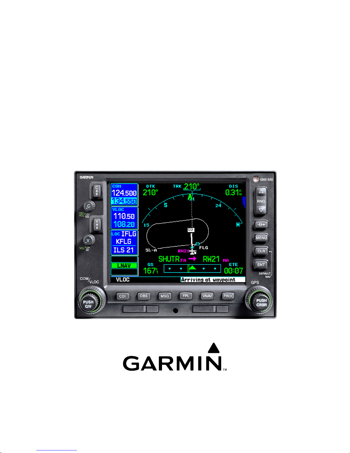
500W SERIES
INSTALLATION MANUAL
GPS 500W and GNS TM 530W/530AW/TAWS
GNS is a trademark of Garmin Ltd. or its subsidiaries and may not be
used without the express permission of Garmin.
190-00357-02 October 2007 Rev. D
Garmin International, Inc.

500W Series Installation Manual
190-00357-02 Rev. D
©Copyright 2006-2007
Garmin Ltd. or its subsidiaries
All Rights Reserved
Except as expressly provided herein, no part of this manual may be reproduced, copied, transmitted,
disseminated, downloaded or stored in any storage medium, for any purpose without the express prior
written consent of Garmin. Garmin hereby grants permission to download a single copy of this manual
and of any revision to this manual onto a hard drive or other electronic storage medium to be viewed and
to print one copy of this manual or of any revision hereto, provided that such electronic or printed copy
of this manual or revision must contain the complete text of this copyright notice and provided further
that any unauthorized commercial distribution of this manual or any revision hereto is strictly prohibited.
Garmin International, Inc.
1200 E. 151
st
Street
Olathe, KS 66062 USA
Telephone: 913-397-8200
Aviation Dealer Technical Support Line (Toll Free): (888) 606-5482
Web Site Address: www.garmin.com
Garmin (Europe) Ltd.
Liberty House
Bull Copse Road
Hounsdown Business Park
Southampton, SO40 9RB, UK
Telephone: 44 (0) 8708501241
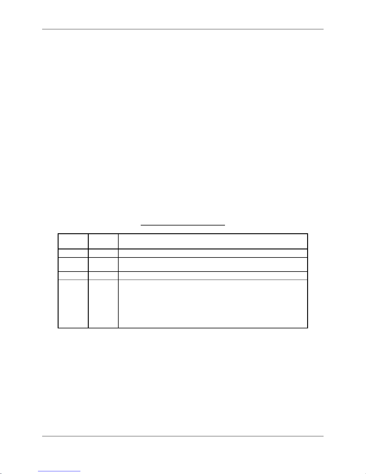
RECORD OF REVISIONS
Revision
A 11/2/06 Production Release
B 11/28/06 Added GA 35 antenna information and corrected wire gauge for main
C 4/5/07 Incorporated customer feedback.
D 10/1/07 Incorporated main software version 3.00 and GPS/WAAS software
Revision
Date
Description
connector power.
version 3.0. Added GA 36, GA 37 and several other non-Garmin
antennas. Changed GPS antenna cable loss requirements. Added
interface interconnects to equipment, including several autopilots,
ACK Technologies altitude encoder, Century AK 1081 GPSS
converter, and Avidyne PFD/MFD. Added GPS vertical guidance
display for EFIS 40/50. Added COM remote discrete.
500W Series Installation Manual Page A
190-00357-02 Rev. D

DOCUMENT PAGINATION
Section Pagination
Table of Contents i - viii
Section 1 1-1 through 1-16
Section 2 2-1 through 2-12
Section 3 3-1 through 3-14
Section 4 4-1 through 4-24
Section 5 5-1 through 5-44
Section 6 6-1 through 6-4
Section 7 7-1 through 7-4
Section 8 8-1 through 8-2
Appendix A A-1 through A-2
Appendix B B-1 through B-2
Appendix C C-1 through C-2
Appendix D D-1 through D-4
Appendix E E-1 through E-6
Appendix F F-1 through F-6
Appendix G G-1 through G-6
Appendix H H-1 through H-54
Page B 500W Series Installation Manual
Rev. D 190-00357-02

This manual reflects the operation of main software version 3.00. Some differences in operation may be
observed when comparing the information in this manual to later software versions.
INFORMATION SUBJECT TO EXPORT CONTROL LAWS
This document may contain information which is subject to the Export Administration Regulations
("EAR") issued by the United States Department of Commerce (15 CFR, Chapter VII, Subchapter C) and
which may not be exported, released, or disclosed to foreign nationals inside or outside of the United
States without first obtaining an export license. A violation of the EAR may be subject to a penalty of up
to 10 years imprisonment and a fine of up to $1,000,000 under Section 2410 of the Export
Administration Act of 1979. Include this notice with any reproduced portion of this document.
WARNING
This product, its packaging, and its components contain chemicals known to the State of
California to cause cancer, birth defects, or reproductive harm. This notice is being
provided in accordance with California's Proposition 65. If you have any questions or
would like additional information, please refer to our web site at
Hg
www.garmin.com/prop65
Perchlorate Material – special handling may apply, See
www.dtsc.ca.gov./hazardouswaste/perchlorate
Lamp(s) inside this product contains mercury and must be recycled or disposed of
according to local, state, or federal laws.
.
.
For more information go to:
www.garmin.com/aboutGarmin/environment/disposal.jsp
.
500W Series Installation Manual Page i
190-00357-02 Rev. D

TABLE OF CONTENTS
PARAGRAPH PAGE
1.
GENERAL DESCRIPTION......................................................................................................... 1-1
1.1 Introduction.................................................................................................................................. 1-1
1.2 Scope............................................................................................................................................ 1-2
1.3 Equipment Description................................................................................................................. 1-2
1.4 Technical Specifications.............................................................................................................. 1-3
1.5 License Requirements................................................................................................................ 1-11
1.6 Regulatory Compliance.............................................................................................................. 1-12
1.7 Database Options and Updates................................................................................................... 1-15
1.8 Fault Detection and Exclusion (FDE)........................................................................................ 1-15
1.9 Limited Warranty....................................................................................................................... 1-16
2. INSTALLATION OVERVIEW................................................................................................... 2-1
2.1 Introduction.................................................................................................................................. 2-1
2.2 Minimum System Configuration.................................................................................................. 2-1
2.3 External Sensors........................................................................................................................... 2-2
2.4 Antenna Considerations............................................................................................................... 2-3
2.5 Mounting Considerations............................................................................................................. 2-7
2.6 Cabling and Wiring Considerations........................................................................................... 2-11
2.7 Air Circulation and Cooling....................................................................................................... 2-11
2.8 Compass Safe Distance.............................................................................................................. 2-11
3. INSTALLATION PROCEDURES.............................................................................................. 3-1
3.1 Unit and Accessories.................................................................................................................... 3-1
3.2 Optional Accessories.................................................................................................................... 3-2
3.3 Database Options......................................................................................................................... 3-3
3.4 Miscellaneous Options................................................................................................................. 3-3
3.5 Optional Reference Material........................................................................................................ 3-3
3.6 Installation Materials Required but Not Provided ....................................................................... 3-4
3.7 Special Tools Required................................................................................................................ 3-5
3.8 Cable Installation ......................................................................................................................... 3-6
3.9 Equipment Mounting.................................................................................................................... 3-8
3.10 Antenna Installation and Connections..................................................................................... 3-9
3.11 Weight and Balance............................................................................................................... 3-10
3.12 Electrical Load Analysis........................................................................................................3-11
3.13 AFMS Completion – Based on Autopilot Type .................................................................... 3-12
4. SYSTEM INTERCONNECT....................................................................................................... 4-1
4.1 Pin Function List.......................................................................................................................... 4-1
4.2 Power, Lighting, And Antennas...................................................................................................4-6
4.3 Altitude Gray Code...................................................................................................................... 4-7
4.4 Main Indicator.............................................................................................................................. 4-8
4.5 Annunciators/Switches............................................................................................................... 4-10
4.6 Serial Data.................................................................................................................................. 4-13
Page ii 500W Series Installation Manual
Rev. D 190-00357-02

COM/VOR/ILS Audio (GNS 530W only)................................................................................. 4-17
4.7
4.8 VOR/ILS Indicator (GNS 530W Only)...................................................................................... 4-19
4.9 RMI/OBI .................................................................................................................................... 4-21
4.10 DME Tuning (GNS 530W Only)........................................................................................... 4-22
4.11 Terrain Awareness Warning System (TAWS)...................................................................... 4-24
5. POST INSTALLATION CONFIGURATION AND CHECKOUT PROCEDURES .................. 5-1
5.1 Mounting And Wiring Check.......................................................................................................5-1
5.2 Connector Engagement Check..................................................................................................... 5-1
5.3 Configuration Mode Operations .................................................................................................. 5-1
5.4 Ground Checks (Configuration Mode) ...................................................................................... 5-25
5.5 Ground Checks (Normal Mode)................................................................................................. 5-28
5.6 Flight Checks.............................................................................................................................. 5-38
5.7 Database Check.......................................................................................................................... 5-39
5.8 Airplane Flight Manual Supplement Checks............................................................................. 5-40
6. TROUBLESHOOTING............................................................................................................... 6-1
6.1 Troubleshooting Procedure.......................................................................................................... 6-1
6.2 Contacting the Factory for Assistance......................................................................................... 6-4
7. LIMITATIONS............................................................................................................................ 7-1
7.1 Operations.................................................................................................................................... 7-1
7.2 Installation.................................................................................................................................... 7-2
7.3 Rotorcraft Installation.................................................................................................................. 7-3
7.4 Aircraft Radio Station License..................................................................................................... 7-3
8. PERIODIC MAINTENANCE...................................................................................................... 8-1
8.1 Equipment Calibration................................................................................................................. 8-1
8.2 VOR Checks................................................................................................................................. 8-1
8.3 Cleaning....................................................................................................................................... 8-1
8.4 Battery Replacement.................................................................................................................... 8-1
APPENDIX A ENVIRONMENTAL QUALIFICATION FORM...........................................................A-1
APPENDIX B STC DATA......................................................................................................................B-1
B.1 STC Information ..........................................................................................................................B-1
B.2 STC Permission............................................................................................................................B-1
B.3 Continued Airworthiness Instructions .........................................................................................B-1
B.4 STC Approved Model List...........................................................................................................B-1
APPENDIX C RESERVED ....................................................................................................................C-1
APPENDIX D 500W SERIES RS-232 AVIATION DATA FORMAT ..................................................D-1
D.1 Electrical Interface.......................................................................................................................D-1
D.2 General Output Format ................................................................................................................D-1
D.3 Output Sentence Type 1...............................................................................................................D-1
D.4 Output Sentence Type 2...............................................................................................................D-3
APPENDIX E 500W SERIES RS-232 FUEL/AIR DATA INPUT FORMAT .......................................E-1
E.1 Electrical Interface.......................................................................................................................E-1
E.2 Shadin Altitude Sentence.............................................................................................................E-1
500W Series Installation Manual Page iii
190-00357-02 Rev. D

Icarus Altitude Sentence ..............................................................................................................E-1
E.3
E.4 Shadin Fuel Flow Sentence..........................................................................................................E-2
E.5 ARNAV / EI Fuel Flow Sentence................................................................................................E-2
E.6 Shadin Fuel/Airdata Computer Sentence.....................................................................................E-3
APPENDIX F MECHANICAL DRAWINGS........................................................................................ F-1
F.1 Drawing List.................................................................................................................................F-1
APPENDIX G APPROVED EQUIPMENT............................................................................................G-1
G.1 Audio Panels ................................................................................................................................G-1
G.2 Air Data Computer.......................................................................................................................G-1
G.3 Altitude Serializer or Fuel/Air Data.............................................................................................G-2
G.4 Autopilots.....................................................................................................................................G-2
G.5 Encoding Altimeter or Blind Encoder (Gray Code) ....................................................................G-2
G.6 EFIS Displays...............................................................................................................................G-3
G.7 EHSI.............................................................................................................................................G-3
G.8 IRU/AHRS...................................................................................................................................G-3
G.9 NAV Indicator..............................................................................................................................G-4
G.10 Weather, Traffic and Terrain...................................................................................................G-4
G.11 DME.........................................................................................................................................G-4
G.12 CDI/HSI Source Selection Annunciators.................................................................................G-5
G.13 Multifunction Displays............................................................................................................G-5
APPENDIX H STC APPROVED INTERCONNECT DIAGRAMS......................................................H-1
H.1. Introduction..............................................................................................................................H-1
H.2. Drawing List ............................................................................................................................H-1
LIST OF FIGURES
Figure 2-1. GPS Antenna Installation Considerations............................................................................. 2-5
Figure 2-2. Source Selection Annunciation Field of View...................................................................... 2-9
Figure 2-3. GPS Navigation/TAWS Annunciation Field of View.........................................................2-10
Figure 3-1. Coaxial Cable Installation..................................................................................................... 3-6
Figure 5-1. MAIN ARINC 429 CONFIG Page........................................................................................ 5-2
Figure 5-2. MAIN RS-232 CONFIG Page............................................................................................... 5-5
Figure 5-3. MAIN SYSTEM CONFIG Page ........................................................................................... 5-6
Figure 5-4. MAIN SYSTEM CONFIG Page ........................................................................................... 5-7
Figure 5-5. MAIN SYSTEM CONFIG Page ........................................................................................... 5-7
Figure 5-6. MAIN INPUTS Page............................................................................................................. 5-8
Figure 5-7. INSTRUMENT PANEL SELF-TEST Page.......................................................................... 5-8
Figure 5-8. MAIN LIGHTING Page........................................................................................................ 5-9
Figure 5-9. Main Lighting Page with Alternate Source......................................................................... 5-10
Figure 5-10. GPS DATE/TIME Page..................................................................................................... 5-10
Figure 5-11. MAIN DISCRETE I/O Page.............................................................................................. 5-11
Figure 5-12. MAIN CDI/OBS CONFIG Page .......................................................................................5-12
Figure 5-13. COM SETUP Page............................................................................................................ 5-14
Figure 5-14. VOR DISCRETE INPUTS Page....................................................................................... 5-15
Figure 5-15. VOR/LOC/GS CDI Page................................................................................................... 5-16
Figure 5-16. VOR/LOC/GS ARINC 429 CONFIG Page....................................................................... 5-17
Figure 5-17. Measurement of GPS Vertical Offset................................................................................5-18
Figure 5-18. GPS Vertical Offset Page.................................................................................................. 5-18
Figure 5-19. STORMSCOPE CONFIG Page.........................................................................................5-19
Page iv 500W Series Installation Manual
Rev. D 190-00357-02

Figure 5-20. STORMSCOPE TEST Page..............................................................................................5-19
Figure 5-21. STORMSCOPE DOWNLOAD DATA Page.................................................................... 5-19
Figure 5-22. TRAFFIC Page (SkyWatch).............................................................................................. 5-20
Figure 5-23. TRAFFIC Page (TCAD)....................................................................................................5-20
Figure 5-24. RYAN TCAD CONFIG Page............................................................................................ 5-20
Figure 5-25. GAD 42 CONFIG Page..................................................................................................... 5-21
Figure 5-26. TAWS AUDIO CONFIG 1 Page.......................................................................................5-21
Figure 5-27. TAWS AUDIO CONFIG 2 Page.......................................................................................5-22
Figure 5-28. GDL CONFIG Page........................................................................................................... 5-24
Figure 5-29. Data Link Diagnostics....................................................................................................... 5-24
Figure F-1. GNS 530W Mounting Rack Dimensions..............................................................................F-3
Figure F-2. GNS 530W Mounting Rack Installation...............................................................................F-4
Figure F-3. GPS 500W Mounting Rack Assembly..................................................................................F-5
Figure F-4. 500W Series Unit Recommended Panel Cutout Dimensions ............................................... F-6
Figure H-1. 500W Series Unit System Interface Diagram...................................................................... H-3
Figure H-2. GNS 530W Typical Installation.......................................................................................... H-4
Figure H-3. GPS 500W Typical Installation........................................................................................... H-6
Figure H-4. Power, Lighting, and Antennas Interconnect ...................................................................... H-8
Figure H-5. Gray Code Encoding Altimeter/Blind Encoder Interconnect............................................ H-11
Figure H-6. Main Indicator Interconnect .............................................................................................. H-12
Figure H-7. KI 209A Main Indicator Interconnect ............................................................................... H-13
Figure H-8. KI 208A Main Indicator Interconnect ............................................................................... H-14
Figure H-9. RS-232 Serial Data Interconnect ....................................................................................... H-15
Figure H-10. ARINC 429 EFIS Interconnect........................................................................................ H-17
Figure H-11. ARINC 429 Sandel EHSI Interconnect (One 500W Series Unit, One Sandel SN3308). H-19
Figure H-12. ARINC 429 Sandel EHSI Interconnect (Two GNS 530W, One Sandel SN3308).......... H-21
Figure H-13. ARINC 429 Sandel EHSI Interconnect (Two GNS 530W, Two Sandel SN3308)......... H-23
Figure H-14. ARINC 429/RS-232 Air Data/IRU/AHRS Interconnect................................................. H-24
Figure H-15. Traffic Advisory System Interconnect............................................................................. H-26
Figure H-16. GTX 330 Interconnect..................................................................................................... H-28
Figure H-17. Weather and Terrain Interconnect................................................................................... H-29
Figure H-18. Audio Panel Interconnect................................................................................................ H-31
Figure H-19. VOR/ILS Indicator Interconnect ..................................................................................... H-33
Figure H-20. RMI/OBI Interconnect..................................................................................................... H-34
Figure H-21. King Serial Panel DME Tuning Interconnect.................................................................. H-35
Figure H-22. King Serial Remote DME Tuning Interconnect.............................................................. H-36
Figure H-23. Parallel 2 of 5 DME Tuning Interconnect....................................................................... H-37
Figure H-24. TAWS Interconnect......................................................................................................... H-38
Figure H-25. Bendix/King Analog Autopilot Interconnect .................................................................. H-39
Figure H-26. Century Autopilot Interconnect....................................................................................... H-40
Figure H-27. S-TEC Autopilot Interconnect......................................................................................... H-42
Figure H-28. ARINC 429 Sandel EHSI Interconnect (One 500W Series Unit, One Sandel SN3500). H-44
Figure H-29. External Navigation Source and GPS Annunciators....................................................... H-46
Figure H-30. Parallel Slip Code DME Tuning Interconnect................................................................. H-48
Figure H-31. Cessna Autopilot Interconnect......................................................................................... H-49
Figure H-32. Bendix Autopilot Interconnect........................................................................................ H-50
Figure H-33. Switches Interconnect...................................................................................................... H-51
Figure H-34. ARINC 429 Avidyne PFD/MFD Interconnect................................................................ H-52
500W Series Installation Manual Page v
190-00357-02 Rev. D

LIST OF TABLES
Table 1-1. 500W Series Units..................................................................................................................1-1
Table 1-2. Antennas Without Operational Limitations............................................................................1-9
Table 1-3. Antennas With Operational Limitations................................................................................1-10
Table 1-4. TSO Authorization................................................................................................................ 1-12
Table 3-1. Catalog Part Numbers............................................................................................................. 3-1
Table 3-2. Standard Kit Accessories........................................................................................................ 3-1
Table 3-3. Recommended Crimp Tools (or Equivalent).......................................................................... 3-5
Table 3-4. Pin Contact Part Numbers.......................................................................................................3-7
Table 3-5. Unit Weights......................................................................................................................... 3-10
Table 3-6. 500W Series Unit Power Input............................................................................................. 3-11
Table 5-1. GNS 500W Series Post-Installation Checkout Log.............................................................. 5-41
Table 6-1. Troubleshooting Guide........................................................................................................... 6-1
Table A-1. Environmental Qualification Form Part Numbers................................................................ A-1
Page vi 500W Series Installation Manual
Rev. D 190-00357-02

500W/530W SERIES HARDWARE MOD LEVEL HISTORY
The following table identifies hardware modification (Mod) Levels for the GPS 500W and GNS
530W. Mod Levels are listed with the associated service bulletin number, service bulletin date, and the
purpose of the modification. The table is current at the time of publication of this manual (see date on
front cover) and is subject to change without notice. Authorized Garmin Sales and Service Centers are
encouraged to access the most up-to-date bulletin and advisory information on the Garmin Dealer
Resource web site at www.garmin.com using their Garmin-provided user name and password.
MOD LEVEL
SERVICE
BULLETIN
NUMBER
SERVICE BULLETIN
DATE
PURPOSE OF MODIFICATION
500W Series Installation Manual Page vii
190-00357-02 Rev. D

This Page Intentionally Left Blank
Page viii 500W Series Installation Manual
Rev. D 190-00357-02

1. GENERAL DESCRIPTION
1.1 Introduction
This manual describes the physical, mechanical, and electrical characteristics, as well as instructions and
other conditions and limitations for installation and approval of the 500W Series panel-mounted units.
The 500W Series includes the GPS 500W (with or without Terrain Awareness and Warning System
(TAWS) or Terrain)), and GNS 530W and GNS 530AW (with or without TAWS or Terrain) panelmounted units. Refer to Section 7, Limitations, for additional information and other considerations.
NOTE
Except where specifically noted, references made to the GNS 530W will equally apply to the
GNS 530AW. Also, except where specifically noted, references made to the GPS 500W or GNS
530W will apply equally to the TAWS version of these units.
Table 1-1. 500W Series Units
MODEL PART NUMBER COLOR NOTES
GPS 500W
GPS 500W w/TAWS
GNS 530W
GNS 530W w/TAWS
GNS 530AW
GNS 530AW w/TAWS
011-01062-00 BLACK
011-01062-10 GRAY
011-01062-40 BLACK NOTE 1
011-01062-50 GRAY NOTE 1
011-01063-00 BLACK
011-01063-10 GRAY
011-01063-40 BLACK NOTE 1
011-01063-50 GRAY NOTE 1
011-01064-00 BLACK
011-01064-10 GRAY
011-01064-40 BLACK NOTE 1
011-01064-45 BLACK 28 VDC UPGRADE UNIT
011-01064-50 GRAY NOTE 1
011-01065-00 BLACK
011-01065-10 GRAY
011-01065-40 BLACK NOTE 1
011-01065-45 BLACK 28 VDC UPGRADE UNIT
011-01065-50 GRAY NOTE 1
011-01066-00 BLACK
011-01066-10 GRAY
011-01066-40 BLACK NOTE 1
011-01066-50 GRAY NOTE 1
011-01067-00 BLACK
011-01067-10 GRAY
011-01067-40 BLACK NOTE 1
011-01067-50 GRAY NOTE 1
Designations: A = 28 VDC Unit with 16w COM transmitter
Note 1: The unit is an upgrade of the non-WAAS unit.
500W Series Installation Manual Page 1-1
190-00357-02 Rev. D

1.2 Scope
The installation instructions and other data contained within this manual are FAA approved under
400W/500W Series AML STC SA01933LA, which is applicable for implementation within airplanes
that are type certificated only under Civil Air Regulation 3 (CAR 3) or 14 Code of Federal Regulations
(CFR) Part 23 (only) into which the Garmin 500W Series unit equipment is qualified for installation and
operational approval. Only the equipment and systems interfaces described in this manual have been
determined to be mutually compatible and are operationally suitable and approved for use as
characterized herein, or within the FAA approved airplane flight manual supplement (AFMS) reflecting
main software version 2.00 and later. Some differences in operation may be observed when comparing
the information in this manual and the FAA approved AFMS to later FAA approved software versions.
Such differences will be identified in revised editions of the FAA approved AFMS characterizing later
software versions, and any applicable limitations and normal or abnormal operating conditions.
It is possible for installers and other appropriately certificated persons to seek FAA approval for
installation and operational use of the 500W Series equipment with systems not identified in this manual,
such as for aircraft certificated under 14 CFR parts 25, 27, or 29, by means of a field approval, STC or
TC. Refer to FAA Advisory Circular (AC) 20-138A and other applicable guidance when applying for
installation and operational approval. AC 21-40 provides guidance for the STC approval process and AC
43-210 provides guidance for the field approval process. If the field approval process is used, it is
advisable to consider the conditions and stipulations in FAA Flight Standards Flight Standards
Information Bulletin for Airworthiness (FSAW), 94-32, “Guidance for Performing Field Approvals of
Installation and Operational Use of Global Positioning Systems (GPS) or GPS with Wide Area
Augmentation Systems (GPS/WAAS), Referred to as Global Navigation Satellite Systems (GNSS)
Equipment”, as revised.
Regardless of applicability of the AML STC or alternative application for installation and operational
approval, prior to completing the installation and before returning the airplane to service, the installer or
other appropriately certificated person is required to complete and submit an FAA Form 337 (OMB No.
2120-0020), “Major Repair and Alteration Airframe, Powerplant, Propeller, or Appliance” to their local
FAA Flight Standards District Office describing the work accomplished. The FAA Form 337 must detail
the equipment and systems to which the respective GPS 500W, GNS 530W, or GNS 530AW is
interfaced and reflect appropriately approved or acceptable data for which follow-on FAA field approval
is being sought. See AC 43.9-1E for instructions for completing the FAA Form 337.
1.3 Equipment Description
The 500W Series units are 6.25 inches wide and 4.60 inches high. The display is a 320 by 234 pixel
color LCD. The units include two removable data cards, one with a Jeppesen database (to be inserted in
the left most card slot), and the second being a TAWS/TERRAIN database (to be inserted in the right
most card slot).
The GPS 500W is a GPS/WAAS unit that meets the requirements of Technical Standard Order (TSO)C146a (specified in Table 1-4) and may be approved for IFR en route, terminal, non-precision, and
precision approach operations when installed in reference to the instructions in this manual as referenced
in the AML STC SA01933LA.
The GNS 530W includes all the features of the GPS 500W and also includes an airborne VHF
communications transceiver and airborne VOR/localizer (LOC) and glideslope (G/S) receivers. The
“AW” model is a 28 VDC unit with a 16 Watt COM transmitter. The GNS 530W/(AW) meets the
requirements of TSOs specified in Table 1-4.
Page 1-2 500W Series Installation Manual
Rev. D 190-00357-02
The 500W Series unit product lens is coated with a special anti-reflective coating which
is very sensitive to skin oils, waxes and abrasive cleaners. CLEANERS CONTAINING
AMMONIA WILL HARM THE ANTI-REFLECTIVE COATING. It is very important
to clean the lens using an eyeglass lens cleaner, which is specified as safe for antireflective coatings and a clean, lint-free cloth.
The use of ground-based cellular telephones while aircraft are airborne is prohibited by
FCC rules. Due to potential interference with onboard systems, the use of ground-based
cell phones while the aircraft is on the ground is subject to FAA regulation 14 CFR
§91.21.
FCC regulation 47 CFR §22.925 prohibits airborne operation of ground-based cellular
telephones installed in or carried aboard aircraft. Ground-based cellular telephones must
not be operated while aircraft are off the ground. When any aircraft leaves the ground,
all ground-based cellular telephones on board that aircraft must be turned off.
Ground-based cell phones that are on, even in a monitoring state, can disrupt GPS
performance.
1.4 Technical Specifications
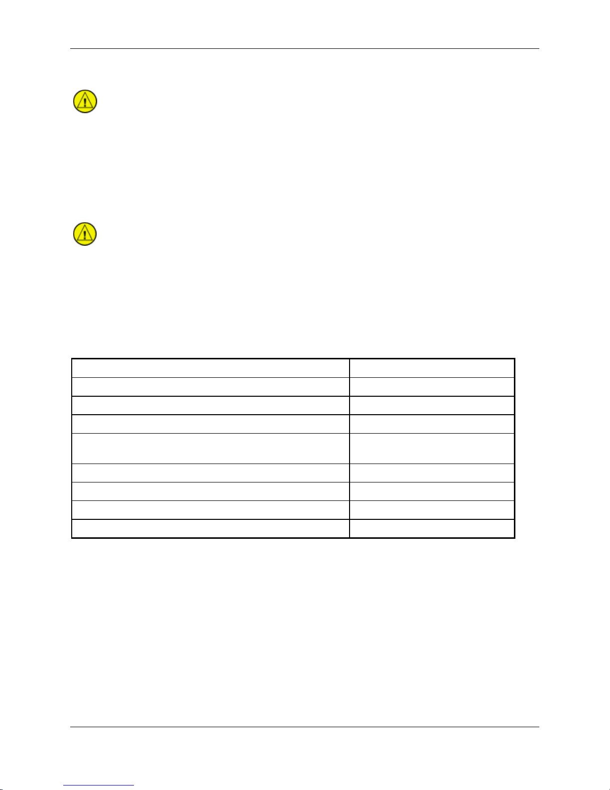
CAUTION
CAUTION
1.4.1 Physical Characteristics
Bezel Height
Bezel Width
Rack Height (Dimple-to-Dimple)
Rack Width
Depth Behind Panel with Connectors (Measured from
face of aircraft panel to rear of connector backshells)
GPS 500W Weight (Unit only)
GPS 500W Weight (With rack and back plate)
GNS 530W Weight (Unit only)
GNS 530W Weight (With rack and back plate)
4.58 in. (116 mm)
6.25 in. (159 mm)
4.60 in. (117 mm)
6.32 in. (161 mm)
11.00 in. (279 mm)
5.7 lbs. (2.59 kg)
6.8 lbs. (3.08 kg)
7.0 lbs. (3.18 kg)
8.2 lbs. (3.72 kg)
500W Series Installation Manual Page 1-3
190-00357-02 Rev. D

1.4.2 General Specifications
Operating Temperature Range
Humidity
Altitude Range
Input Power Requirements
Input Voltage Range - All Units (Main
Connector)
Input Voltage Range (COM Connector)
GNS 530W
Input Voltage Range (COM Connector)
GNS 530AW
GPS 500W (Main Connector)
GNS 530W, GNS530AW (Main Connector)
GNS 530W (COM Connector)
GNS 530AW (COM Connector)
Superflag Power Requirements
Environmental Testing
The display on the 500W Series unit is a sunlight readable LCD display.
Display Size
Active Area
Resolution
Viewing Angle
(with a 5:1 contrast ratio, min)
Viewing Distance
-20°C to +55°C. For more details see Environmental
Qualification Form on the Dealers Only page on
www.garmin.com. See Appendix A for part numbers.
95% non-condensing
-1,500 ft to 50,000 ft
10 to 33.2 VDC
11 to 33 VDC
24.1 to 33 VDC
800 mA @ 28 VDC (maximum)
1.6 A @ 14 VDC (maximum)
1.4 A @ 28 VDC (maximum)
3.0 A @ 14 VDC (maximum)
15 mA @ 28 VDC (receive)
3.0 A @ 28 VDC (transmit)
15 mA @ 14 VDC (receive)
6.0 A @ 14 VDC (transmit)
15 mA @ 28 VDC (receive)
3.0 A @ 28 VDC (transmit)
500 mA maximum per superflag output
See Environmental Qualification Form on the Dealers
Only page on www.garmin.com. See Appendix A for
part numbers.
5.0” diagonal
4.02” (W) x 2.95” (H)
320 x 234 pixels
Left/Right:
Up:
Down:
36 inches maximum
60°
35°
60°
Page 1-4 500W Series Installation Manual
Rev. D 190-00357-02

1.4.3 GPS Specifications
Number Of Channels
Frequency
Sensitivity (Acquisition, No
Interference)
Sensitivity (Drop Lock)
Dynamic Range
Lat/Lon Position Acc uracy
Velocity
TTFF (Time To First Fix)
Reacquisition
Position Update Interval
1 PPS (Pulse Per Second)
Datum
SATCOM Compatibility
Antenna Power Supply
15 (12 GPS and 3 GPS/WAAS/SBAS)
1575.42 MHz L1, C/A code
-134.5 dBm GPS
-135.5 dBm WAAS
-144 dBm
> 20 dB
<1.25 meter RMS horizontal, <2 meter vertical, with WAAS
1000 knots maximum (above 60,000 ft)
1:45 min. typical with current almanac, position, and time
10 seconds typical
0.2 sec (5 Hz)
±275 Nsec of UTC second
WGS-84
SATCOM compatibility is dependent upon antenna selection.
See Section 1.4.8 for additional information.
35 mA typical, 40 mA max at 4.7 VDC
500W Series Installation Manual Page 1-5
190-00357-02 Rev. D

1.4.4 COM Transceiver Specifications (GNS 530W Only) **
Audio Output
Audio Response
Audio Distortion
AGC Characteristics
Sensitivity
Squelch
Selectivity
Spurious Response
Transmitter Power
Transmitter Duty Cycle
Modulation Capability
Carrier Noise Level
Frequency Stability
Demodulated Audio Distortion
Sidetone
Demodulated Audio Response
100 mW minimum into a 500Ω load.
Less than 6 dB of Variation between 350 and 2500 Hz.
The distortion in the receiver audio output does not exceed
15% at all levels up to 100 mW.
The audio output does not vary by more than 6 dB when the
level of the RF input signal, modulated 30% at 1000 Hz, is
varied from 5 μV to 450,000 μV.
(S+N)/N on all channels is greater than 6 dB when the RF
level is 2 μV (hard) modulated 30% at 1000 Hz at rated audio.
2 μv ±6 dB for 25 kHz channels.
3 μv ±6 dB for 8.33 kHz channels.
6 dB BW is greater than ±8 kHz for 25 kHz channeling.
60 dB BW is less than ±25 kHz for 25 kHz channeling.
6 dB BW is greater than ±2.778 kHz for 8.33 kHz channeling.
60 dB BW is less than ±7.37 kHz for 8.33 kHz channeling.
Greater than 85 dB.
At least 10 Watts*, 16 watts for “AW” models.
Recommended 10% maximum.
The modulation is not less than 70% and not greater than
98% with a standard modulator signal applied to the
transmitter.
At least 45 dB (S+N)/N.
0.0005%
Less than 10% distortion when the transmitter is modulated at
least 70%.
1.4 V
RMS into a 500Ω load when the transmitter is modulated
at least 70%.
Less than 6 dB when the audio input frequency is varied from
350 to 2500 Hz.
* C37d Class 4 & 6 may not provide suitable COM transmit range for some high-altitude aircraft.
** Specifications shown apply at nominal input voltages of 14 VDC or 28 VDC, as applicable, and with
a nominal 50 ohm resistive load at the antenna connector.
Page 1-6 500W Series Installation Manual
Rev. D 190-00357-02

1.4.5 VOR Specifications (GNS 530W Only)
Receiver Audio Sensitivity
Course Deviation Sensitivity
Flag
AGC Characteristics
Spurious Response
VOR OBS Bearing Accuracy
Audio Output
Audio Response
Audio Distortion
At -103.5 dBm (S+N)/N is not less than 6 dB.
-103.5 dBm or less for 60% of standard deflection.
The VOR Course Deviation Flag must
a) in the absence of an RF signal.
b) in the absence of the 9960 Hz modulation.
c) in the absence of either one of the two 30 Hz modulations.
d) When the level of a standard VOR deviation test signal
produces less than a 50% of standard deflection.
From -99 dBm to -13 dBm input of a Standard VOR Audio Test
Signal, audio output level does not vary more than 3 dB.
Greater than 80 dB.
The bearing information as presented to the pilot does not have an
error in excess of 2.7° as specified by RTCA DO-196 and EuroCAE
ED-22B.
A minimum 100 mW into a 500Ω load.
Less than 6 dB of variation between 350 and 2500 Hz. Except the
1020 Hz Ident Tone is at least 20 dB down in voice mode.
The distortion in the receiver audio output does not exceed 10% at
all levels up to 100 mW.
1.4.6 LOC Specifications (GNS 530W Only)
Receiver Audio Sensitivity
Course Deviation Sensitivity
Flag
AGC Characteristics
Selectivity
Spurious Response
Centering Accuracy
Audio Output
Audio Response
Audio Distortion
At -103.5 dBm (S+N)/N is not less than 6 dB.
-103.5 dBm or less for 60% of standard deflection.
The LOC Course Deviation Flag must
a) In the absence of an RF signal.
b) When either the 90 or 150 Hz modulating signals is removed
and the other is maintained at its normal 20%.
c) In the absence of both 90 and 150 Hz modulation.
d) When the level of a standard localizer deviation test signal
produces less than a 50% of standard deflection.
From -86 dBm and -33 dBm input of a Standard VOR Audio Test
Signal, audio output level does not vary more than 3 dB.
Nose Bandwidth: The input signal level required to produce the
reference AGC voltage does not vary more than 6 dB over the
input signal frequency range of ± 9 kHz from the assigned channel
frequency.
Skirt Bandwidth: The input signal level required to produce
reference AGC voltage is at least 70 dB greater than the level
required to produce reference AGC voltage at the assigned
channel frequency at ± 36 kHz from the assigned channel
frequency.
Greater than 80 dB.
Typical 0 ± 3 mV (Max error 9.9 mV per RTCA DO-195).
A minimum 100 mW into a 500Ω load.
Less than 6 dB of Variation between 350 and 2500 Hz. Except the
1020 Hz Ident Tone is at least 20 dB down in voice mode.
The distortion in the receiver audio output does not exceed 10% at
all levels up to 100 mW.
be flagged:
be flagged:
500W Series Installation Manual Page 1-7
190-00357-02 Rev. D

1.4.7 Glideslope Specifications (GNS 530W Only)
Sensitivity
Centering Accuracy
Selectivity
Standard Deflection
Flag
-87 dBm or less for 60% of standard deflection.
0 ±.0091 ddm or 0 ±7.8 mV.
The course deviation is 0 ddm ± .0091 ddm when using the
Glideslope Centering Test Signal as the RF frequency is varied ±17
kHz from the assigned channel.
At frequencies displaced by ±132 kHz or greater, the input signal is
at least 60 dB down.
a) With a standard deflection ‘FLY DOWN’ condition (90 Hz
dominant), the output is -78 mV ±7.8 mV.
b) With a standard deflection ‘FLY UP’ condition (150 Hz
dominant), the output is +78 mV ±7.8 mV.
The unit Flags:
a) When the level of a standard deviation test signal produces
50% or less of standard deflection of the deviation indicator.
b) In the absence of 150 Hz modulation.
c) In the absence of 90 Hz modulation.
d) In the absence of both 90 Hz and 150 Hz modulation.
e) In the absence of RF.
Page 1-8 500W Series Installation Manual
Rev. D 190-00357-02

1.4.8 GPS Antenna Requirements
Antenna performance is critical to the GPS/WAAS operation. The antennas listed in Table 1-2 and
Table 1-3 are approved for installation with the 500W Series units with specified limitations. Refer to the
following sections and tables for selection of the GPS/WAAS antenna.
1.4.8.1 Antennas Without IFR GPS Operational Limitations
The list of TSO-C144 antennas shown in Table 1-2 allow the 500W Series models to meet TSO-C146a
requirements without the operational limitations specified in the Limitations Section 7.1.1 of this
manual.
Table 1-2. Antennas Without IFR GPS Operational Limitations
Model / Description Mount Style
Screw mount,
GA 35, GPS/WAAS
GA 36, GPS/WAAS
GA 37, GPS/WAAS
+XM
Comant ,
GPS/WAAS+VHF
[3]
Comant
GPS/WAAS +VHF
[3]
Comant
GPS/WAAS
+XM+VHF [3]
Teardrop
footprint
[1]
Screw mount,
ARINC 743
Screw mount,
ARINC 743
Screw mount,
Teardrop
COM
Screw mount,
Teardrop
Screw mount,
Teardrop
COM
Conn
Type
TNC
TNC
TNC
TNC
TNC
BNC
[2]
TNC
BNC
[2]
TNC
TNC
BNC
[4]
Mfr Part Number
Garmin 013-00235-00 013-00235-00
Aero
Antenna
Garmin 013-00244-00 013-00244-00
Aero
Antenna
Garmin 013-00245-00 013-00245-00
Aero
Antenna
Comant CI-2580-200 N/A
Comant CI-2728-200 N/A
Comant CI-2728-410 N/A
A T575-93G W -TNCF-
000-RG-27-NM
AT575-126GW-
TNCF-000-RG-27-
NM
AT2300-126GW-
TNCF-000-RG-27-
NM
Garmin Order
Number
013-00235-00
013-00244-00
013-00245-00
Additional
Requirements
Must have
GPS software
V3.0 or later.
[1] Same mounting hole pattern as GA 56, but GA 35 antenna has a physically larger footprint.
[2] The GPS/WAAS connector is a TNC type. The VHF connector is a BNC type.
[3] Installation of this antenna is not covered by the Garmin GA Antenna AML STC SA01695SE.
[4] The GPS/WAAS connector is a TNC type. The XM connector is a TNC type. The VHF connector is
a BNC type.
500W Series Installation Manual Page 1-9
190-00357-02 Rev. D

1.4.8.2 Antennas With IFR GPS Operational Limitations
The list of TSO-C144 antennas shown in Table 1-3 allow the 500W Series models to meet TSO-C146a
requirements with the operational limitations specified in the Limitations Section 7.1.1 of this manual.
Table 1-3. Antennas With IFR GPS Operational Limitations
Model / Description Mount Style
GA 56A,
GPS/WAAS
Antenna [3]
GA 56W,
GPS/WAAS
Antenna [3]
GA 57, GPS/WAAS
and FIS Antenna
[3]
A33, GPS/WAAS
Antenna
A34, GPS/WAAS
Antenna
Screw Mount,
ARINC 743
Footprint
Stud Mount ,
Teardrop
Footprint [1]
Screw Mount,
ARINC 743
Footprint
Screw Mount TNC
Screw Mount,
Teardrop
Footprint [2]
Conn
Type
BNC Garmin 011-01154-00 010-10599-00
BNC Garmin 011-01111-00 010-10561-01
BNC
TNC
[4]
TNC
Mfr Part Number
Garmin 011-01032-00 010-10604-00
Garmin A T 590-1 104 N/A
Aero
Antenna
Gar min A T 590-1112 013-001 13-00
Aero
Antenna
A T 575-9UW-TNCF-
000-05-26-NM
A T575-93W-TNCF-
000-05-26-NM
Garmin Order
Number
N/A
013-001 13-00
Additional
Requirements
Operational
limitations in
Section 7.1.1
of this manual
apply.
[1] Same footprint and mounting hole pattern as GA 56.
[2] Same mounting hole pattern as GA 56, but A34 antenna has a physically larger footprint
.
[3] Antenna is not compatible with SATCOM. An alternate antenna should be used for installations
equipped with SATCOM.
[4] The GPS/WAAS antenna connector is a BNC type. The XM antenna connector is a TNC type.
Page 1-10 500W Series Installation Manual
Rev. D 190-00357-02

1.5 License Requirements
The Telecommunications Act of 1996, effective February 8, 1996, provides the FCC discretion to
eliminate radio station license requirements for aircraft and ships. The GNS 530W installation must
comply with current transmitter licensing requirements. To find out the specific details on whether a
particular installation is exempt from licensing, please visit the FCC web site
http://wireless.fcc.gov/aviation.
If an aircraft license is required, make application for a license on FCC form 404, Application for
Aircraft Radio Station License. The FCC also has a fax-on-demand service to provide forms by fax. The
GNS 530W owner accepts all responsibility for obtaining the proper licensing before using the
transceiver.
CAUTION
THE VHF TRANSMITTER IN THIS EQUIPMENT IS GUARANTEED TO MEET
FEDERAL COMMUNICATIONS COMMISSION ACCEPTANCE OVER THE
OPERATING TEMPERATURE RANGE. MODIFICATIONS NOT EXPRESSLY
APPROVED BY GARMIN COULD INVALIDATE THE LICENSE AND MAKE IT
UNLAWFUL TO OPERATE THE EQUIPMENT.
500W Series Installation Manual Page 1-11
190-00357-02 Rev. D

1.6 Regulatory Compliance
1.6.1 TSO and Advisory Circular References
The conditions and tests required for TSO approval of this article are minimum performance standards.
It is the responsibility of those installing this article either on or within a specific type or class of aircraft
to determine that the aircraft installation conditions are within the TSO standards. TSO articles must
have separate approval for installation in an aircraft. The article may be installed only in compliance
with 14 CFR part 43 or the applicable airworthiness requirements.
For aircraft on the AML for the 400W/500W Series STC SA01933LA, the TSO design approval has
been determined to be adequate by the STC, which constitutes the separate installation design approval.
Table 1-4. TSO Authorization
Function TSO
TSO-C37d, Transmitter, 100nm range RTCA/DO-186A,
COM
TSO-C38d, Receiver RTCA/DO-186A,
TSO-C34e, Glideslope
VOR/ILS
GPS/WAAS TSO-C146a, GPS/WAAS RTCA/DO-229C, Class 3 Level B
MFD TSO-C113, Display SAE AS 8034 Level B,C,D
TAWS TSO-C151b, TAWS Class B Level C
TSO-C36e, Localizer
TSO-C40c, VHF Omni Range
Minimum Performance
Standard
Class 4 & 6
Class 3 & 5 for “A” models
Class C & E
RTCA/DO-192
RTCA/DO-195
RTCA/DO-196
Software
RTCA/DO-178B
Level C, D [1]
Level C
[1] Version 2.XX main software uses Level D software for the COM tuning function. All other COM
functions are Level C. In later versions of the main software, the software level for the COM tuning
function is Level C.
• AC 20-67B, Airborne VHF Communications Equipment Installations
• AC43.13-1B, Acceptable Methods, Techniques and Practices - Aircraft Inspection and Repair
• AC43.13-2A, Acceptable Methods, Techniques and Practices - Aircraft Alterations
System Function DO-178B Level
Operating System B
GPS Navigation Information B
VOR Information C
LOC/Glideslope Information C
VHF Communication C
TAWS (Class B) Functionality C
Display of altitude, heading, course, speed, and track C
Display of other information - moving map, terrain, flight plan overlay and flight mode,
TAS/TIS traffic information, XM Weather data, data from passive lightning detection
equipment, checklist and timer
Terrain D
D
Unauthorized changes or modifications to any 500W Series unit product may void the
compliance to required regulations and authorization for continued equipment usage. All
500W Series unit functions are design approved under the TSO. Airworthiness approval
for installation and operational use is recognized under AML STC SA01933LA. If
additional information (drawing lists and software documentation) is required to
substantiate aircraft installation or operational approval, contact Garmin Customer
Support for assistance. Garmin does not provide design or certification documentation,
including software data, other than to certification authorities.
Page 1-12 500W Series Installation Manual
Rev. D 190-00357-02
NOTE

1.6.2 TSO Deviations
TSO Deviation
TSO-C34e
TSO-C36e
TSO-C37d
TSO-C38d
TSO-C40c
TSO-C113
TSO-C146a
1. Garmin was granted a deviation from TSO-C34e to use RTCA/DO-178B instead of RTCA/DO-178A to
demonstrate compliance for the verification and validation of the computer software.
2. Garmin was granted a deviation from TSO-C34e to use RTCA/DO-160C instead of RTCA/DO-160B as
the standard for Environmental Conditions and Test Procedures of Airborne Equipment.
1. Garmin was granted a deviation from TSO-C36e to use RTCA/DO-178B instead of RTCA/DO-178A to
demonstrate compliance for the verification and validation of the computer software.
2. Garmin was granted a deviation from TSO-C36e to use RTCA/DO-160C instead of RTCA/DO-160B as
the standard for Environmental Conditions and Test Procedures of Airborne Equipment.
1. Garmin was granted a deviation from TSO-C37d to use RTCA/DO-178B instead of RTCA/DO-178A to
demonstrate compliance for the verification and validation of the computer software.
2. Garmin was granted a deviation from TSO-C37d paragraph (a)(1) to allow using RTCA /DO-186A
instead of RTCA/DO-186 to specify minimum performance standards.
3. Garmin was granted a deviation from TSO-C37d to allow a 6dB reduction of transmitter power during the
Normal Operating Conditions – Emergency Operation Voltage as described in RTCA/DO-186A paragraph
2.5.13.1 and RTCA/DO-160C paragraph 16.5.2.1.
4. Garmin was granted a deviation from TSO-C37d paragraph (a)(5) to allow 8.33 kHz channel spacing in
addition to the 25 kHz spacing.
5. Garmin was granted a deviation from TSO-C37d paragraph (b)(1) to allow marking to call our 8.33 kHz
channel spacing in addition to the 25 kHz spacing.
1. Garmin was granted a deviation from TSO-C38d to use RTCA/DO-178B instead of RTCA/DO-178A to
demonstrate compliance for the verification and validation of the computer software.
2. Garmin was granted a deviation from TSO-C38d paragraph (a)(1) to allow using RTCA /DO-186A
instead of RTCA/DO-186 to specify minimum performance standards.
3. Garmin was granted a deviation from TSO-C38d paragraph (a)(5) to allow 8.33 kHz channel spacing in
addition to the 25 kHz spacing.
1. Garmin was granted a deviation from TSO-C40c to use RTCA/DO-178B instead of RTCA/DO-178A to
demonstrate compliance for the verification and validation of the computer software.
2. Garmin was granted a deviation from TSO-C40c to use RTCA/DO-160C instead of RTCA/DO-160B as
the standard for Environmental Conditions and Test Procedures for Airborne Equipment.
1. Garmin was granted a deviation from TSO-C113 section 2.1.2 (4) to use RTCA/DO-178B instead of
RTCA/DO-178A to demonstrate compliance for the verification and validation of the computer software.
2. Garmin was granted a deviation from TSO-C113 section 2.1.2 (3) to use RTCA/DO-160D instead of
RTCA/DO-160B as the standard for Environmental Conditions and Test Procedures for Airborne
Equipment.
1. Garmin was granted a deviation from TSO-C146a for the requirement to use as a specific “NAV” labeled
key. RTCA/DO-229c Table 2-5 lists the function “Access to primary navigation display (Section 2.2.1.4.1)”
with a label “NAV”.
2. Garmin was granted a deviation from TSO-C146a not to implement RTCA/DO-229C paragraph 2.2.3.2.2
which states “The equipment shall allow the pilot to initiate the missed approach with manual action. It shall
be possible to take this action before crossing the MAWP, in which case the equipment shall automatically
initiate the missed approach procedure at the MAWP.”
3. Garmin was granted a deviation from TSO-C146a not to implement RTCA/DO-229C paragraph 2.2.4.2.3
which states “If the aircraft is past the FPAP – (length offset), and the pilot has not already activated the
missed approach, the receiver shall automatically transition to missed approach guidance.” This
requirement is being eliminated in DO-229D.
4. Garmin was granted a deviation from TSO-C146a from RTCA/DO-229C paragraphs 2.2.4.6.4 and
2.2.5.6.4 not to use the low altitude alerting function when the 500W series unit has TERRAIN or TAWS
enabled and is not in one of the following states: FAIL, N/A, TEST, or INHIBIT. When neither TERRAIN nor
TAWS is enabled, or when one is enabled but the current state is FAIL, N/A, TEST, or INHIBIT, the low
altitude alert described in DO-229C 2.2.4.6.4 and 2.2.5.6.4 is used.
5. Garmin was granted a deviation from TSO-C146a not to implement RTCA/DO-229C paragraph
2.2.1.4.9.c which states “BRG to or from a VOR: The bearing is based on the true-to-magnetic conversion
at the waypoint location, using the same magnetic conversion as used to define the path.” Instead, the
“user” (current) location will be used. The RTCA/DO-229C paragraph 2.2.1.4.9.c requirement is being
eliminated in DO-229D.
6. Garmin was granted a deviation from TSO-C146a paragraph 4.b. which defines “each separate
component that is easily removable (without hand tools), each interchangeable element, and each
separate subassembly of the article that the manufacturer determines may be interchangeable must be
permanently and legibly marked with at least the name of the manufacturer, manufacturer’s subassembly
part number, and the TSO number.”
500W Series Installation Manual Page 1-13
190-00357-02 Rev. D

TSO Deviation
C146a
cont’d
Note 1: No. 7 deviation is applicable with GPS software version 2.X
7. Garmin was granted a deviation from TSO-C146a from RTCA/DO-229C paragraphs 2.1.1.10, 2.1.1.7,
2.1.1.8.1, 2.1.1.8.2, 2.1.1.9, 2.1.2.1, 2.1.3.1, 2.1.4.1.4, 2.1.4.1.5 and 2.1.5.1 in the form of an operational
limitation to achieve an equivalent level of safety. The operational limitation is based on:
a. The ability to use antennas that may not meet the minimum gain performance requirements of DO-
228.
b. The ability to mitigate the effects of the different gain characteristics of those antennas by increasing
the effective mask angle through operational limitations.
c. The ability to further increase the effective mask angle, through operational limitations, to a level
commensurate with test conditions used in the original TSO qualification tests.
d. The ability to use -128 dBmic as the minimum GPS satellite signal-in-space for the purpose of
assessing the operational limitation.
e. The ability to use -128 dBmic as the minimum SBAS satellite signal-in-space for the purpose of
assessing the operational limitation. NOTE 1
8. Garmin was granted a deviation from TSO-C146a paragraph 2.1.1.9 to use 20 seconds (instead of 10
seconds) to reacquire a dropped satellite under the conditions described in the paragraph. The 20 second
period is the time period specified by the new DO-229d. NOTE 1
No. 8 deviation is applicable with GPS software version 3.0 or newer.
1.6.3 FCC Grant of Equipment Authorization
GNS 530W FCC ID: IPH-0021400
GNS 530AW FCC ID: IPH-0061100
Page 1-14 500W Series Installation Manual
Rev. D 190-00357-02

1.7 Database Options and Updates
1.7.1 Aviation Database
The aviation database resides on a database card that is inserted in the left card slot on the unit front
panel.
The database is generated on periodic cycles from current Jeppesen data and converted to the format used
by the 500W Series unit products. The data conversion process is performed using software that is
developed and maintained under Garmin document control processes according to RTCA/DO-200A,
Standards for Processing Aeronautical Data.
The database can be updated by purchasing a database subscription from Jeppesen. The database updates
include either replacing or re-programming the database card and inserting the updated card in the left
card slot on the unit front panel. Contact Jeppesen at 800-621-5377 or www.jeppesen.com for more
information and instructions.
Contact Garmin for more information on databases available for the GPS 500W/GNS 530W.
1.7.2 TAWS/Terrain Database
The TAWS/Terrain database resides on a database card that is inserted in the right card slot on the unit
front panel.
The TAWS/Terrain database which serves both functions of Terrain Awareness and Warning System
(TAWS) and the standard configured 500W Series unit providing Terrain functionality is available for
updating on periodic cycles and is available from Garmin. TAWS/Terrain database updates can be
accomplished by replacing or reprogramming the database card and inserting the updated card in the right
card slot on the unit front panel. The TAWS/Terrain database can be downloaded via the internet and the
card programmed using a USB programmer available from Garmin. Contact Garmin at 800-800-1020 or
www.garmin.com for more information or instructions.
1.8 Fault Detection and Exclusion (FDE)
The 500W Series unit, when installed as defined in this manual, complies with the requirements for GPS
primary means navigation in oceanic and remote airspace when used in conjunction with the FDE
Prediction program included with the GNS 400W/500W Series Trainer CD.
The 500W Series unit includes fault detection and exclusion (FDE), which is active for all flight phases
including oceanic and remote operations, en route and terminal, and precision and non-precision
approaches, and does not require any pilot interaction. The FDE consists of two parts:
1. The fault detection function detects a satellite failure that can affect navigation; and
2. The exclusion function is the capability to exclude one or more failed satellites and prevent them
from affecting navigation.
The FDE Prediction program, included with the GNS 400W/500W Series Trainer CD, is used to predict
FDE availability. The FDE Prediction program must be used prior to oceanic or remote area flights for all
operators using the 500W Series unit as primary means navigation under FAR parts 91, 121, 125, and
135.
500W Series Installation Manual Page 1-15
190-00357-02 Rev. D

1.9 Limited Warranty
This Garmin product is warranted to be free from defects in materials or workmanship for two years from
the date of purchase. For WAAS upgrade of this product, the warranty is separate and described in the
service record or statement.
Products bought through online auctions are not eligible for rebates or other special offers from Garmin.
Online auction confirmations are not acceptable for warranty verification. To obtain warranty service, an
original or copy of the sales receipt from the original retailer is required. Garmin will not replace missing
components from any package purchased through an online auction.
Within a warranty period, Garmin will, at its sole option, repair or replace any components that fail in
normal use. Such repairs or replacement will be made at no charge to the customer for parts or labor,
provided that the customer is responsible for any transportation cost. This warranty does not cover
failures due to abuse, misuse, accident or unauthorized alteration or repairs. SUCH REMEDY SHALL
BE YOUR SOLE AND EXCLUSIVE REMEDY FOR ANY BREACH OF WARRANTY
THE WARRANTIES AND REMEDIES CONTAINED HEREIN ARE EXCLUSIVE AND IN LIEU OF
ALL OTHER WARRANTIES EXPRESS OR IMPLIED OR STATUTORY, INCLUDING ANY
LIABILITY ARISING UNDER ANY WARRANTY OF MERCHANTABILITY OR FITNESS FOR A
PARTICULAR PURPOSE, STATUTORY OR OTHERWISE. THIS WARRANTY GIVES YOU
SPECIFIC LEGAL RIGHTS, WHICH MAY VARY FROM STATE TO STATE.
IN NO EVENT SHALL GARMIN BE LIABLE FOR ANY INCIDENTAL, SPECIAL, INDIRECT OR
CONSEQUENTIAL DAMAGES, WHETHER RESULTING FROM THE USE, MISUSE, OR
INABILITY TO USE THIS PRODUCT OR FROM DEFECTS IN THE PRODUCT. Some states do not
allow the exclusion of incidental or consequential damages, so the above limitations may not apply to
you.
To obtain warranty service, contact your local Garmin Authorized Service Center. For assistance in
locating a Service Center near you, call Garmin Customer Service at one of the numbers shown below.
Garmin International, Inc. Garmin (Europe) Ltd.
1200 East 151
st
Street Liberty House
Olathe, Kansas 66062, U.S.A. Bull Copse Road
Phone: 913/397.8200 Hounsdown Business Park
FAX: 913/397.0836 Southampton, SO40 9RB, UK
Telephone: 44(0) 8708501241
Page 1-16 500W Series Installation Manual
Rev. D 190-00357-02

2. INSTALLATION OVERVIEW
2.1 Introduction
Always follow acceptable avionics installation practices per AC 43.13-1B, AC 43.13-2A, or later FAA
approved revisions of these documents. The GPS/WAAS installation instructions have been prepared to
meet the guidance material contained in AC 20-138A “Airworthiness Approval of Global Navigation
Satellite System (GNSS) Equipment”. The communications installation instructions have been prepared
to meet the guidance material defined by AC 20-67B, “Airborne VHF Communications Equipment
Installations”. Follow the installation procedure in this section, as it is presented, to accomplish a
successful installation. Read the entire section before beginning the work.
Prior to installation, consider the structural integrity of the 500W Series installation as defined in AC
43.13-2A, Chapter 1. Complete an electrical load analysis in accordance with AC 43.13-1B, Chapter 11,
on the aircraft prior to starting modification to ensure aircraft has the ability to carry the 500W Series
load. Refer to Section 3.12 to calculate the total power consumption of each 500W Series mode of
operation. Document the results of the electrical load analysis on the FAA Form 337.
Once the installation is complete, perform the post installation checkout before closing the work area in
case problems occur.
2.2 Minimum System Configuration
2.2.1 VFR Installation
The minimum 500W Series unit installation requires the following items for a VFR Installation:
• GNS 500W Series unit (installed in the aircraft manufacturer approved location for 6.25 inch
wide avionics equipment)
• GPS antenna is required for GPS navigation functions.
• An external CDI is required for installations using the VOR navigation and glideslope
information.
• A NAV antenna is required for VHF NAV functions.
• A COM antenna is required for COM functions.
VFR installations must be placarded “GPS LIMITED TO VFR USE ONLY” in clear view of the pilot.
2.2.2 IFR GPS Installation
In order for the 500W Series unit to be utilized for IFR GPS Navigation, the criteria in Section 2.2.1 must
be met in addition to the following:
• An External CDI/HSI indicator must be installed in the pilot’s primary field-of-view (or in the
aircraft manufacturer approved mounting location). The indicator must have a vertical deviation
indicator (GS) in order to perform VNAV operations/approaches.
• Any annunciation required for Source Selection or IFR GPS Navigation must meet the
acceptable field-of-view requirements as noted in Section 2.5.1.
NOTE
To take full advantage of the 500W Series unit capabilities, an optional barometric
altitude source is recommended for automatic sequencing of fix-to-altitude (FA) and
hold-to-altitude (HA) leg types. If no barometric altitude data is provided to the 500W
Series unit, FA and HA legs must be manually sequenced.
500W Series Installation Manual Page 2-1
190-00357-02 Rev. D

2.2.3 IFR VOR/LOC/GS Installation
The minimum GNS 530W installation requires the following items for an IFR VOR/LOC/GS
installation:
• GNS 530W (installed in the aircraft manufacturer approved location)
• GPS antenna, VOR/LOC antenna, glideslope antenna, and COM antenna.
• An External CDI/HSI indicator must be installed in the pilot’s primary field-of-view (or in the
aircraft manufacturer approved mounting location). The indicator must have a vertical deviation
indicator for glideslope and VNAV operations/approaches.
• Any annunciation required for Source Selection or IFR GPS Navigation must meet the
acceptable field-of-view requirements as noted in Section 2.5.1.
2.3 External Sensors
When the 500W Series unit is installed with external sensors, these sensors must be installed in
accordance with the manufacturer's data. This manual does not provide information for the installation of
specific external sensors.
The 500W Series unit can accept data from multiple altitude, heading, and baro correction sources. If
multiple sources are used, the 500W Series unit will accept data as described below.
NOTE
Barometric altitude is not required by the 500W Series unit to meet the requirements of
TSO C146a.
2.3.1 Multiple Uncorrected Pressure Altitude Sources
The 500W Series unit can accept altitude from a Gray Code or RS-232 altitude encoder, fuel/air data
computer (FADC), ARINC 429 air data computer (ADC), ARINC 429 EFIS, and ARINC 429 traffic
advisory system.
If multiple sources of altitude data are supplied to the GPS 500W/GNS 530W, only valid data from the
highest priority source is used (input priority cannot be configured). If the highest priority source
becomes unavailable, data is taken from the next-highest priority source. The priorities of the altitude
sources are as follows (from highest to lowest):
1. ARINC 429 ADC
2. ARINC 429 EFIS
3. ARINC 429 Traffic Advisory System
4. RS-232 FADC
5. RS-232 Altitude Encoder
6. Parallel Altitude Encoder (Gray Code)
2.3.2 Multiple Baro-Corrected Altitude Sources
The 500W Series unit can accept baro-corrected altitude from an ARINC 429 ADC, ARINC 429 EFIS,
RS-232 FADC, and GTX 33/330 transponder.
If multiple sources of baro-corrected altitude data are supplied to the GPS 500W/GNS 530W, only valid
data from the highest priority source is used. If the highest priority source becomes unavailable, data is
taken from the next-highest priority source. The priorities of the baro-corrected altitude sources are as
follows (from highest to lowest):
Page 2-2 500W Series Installation Manual
Rev. D 190-00357-02
 Loading...