

Garmin GPS 500, GNS 530, GNS 530A, GNS 530 TAWS Installation Manual
500 SERIES
INSTALLATION MANUAL
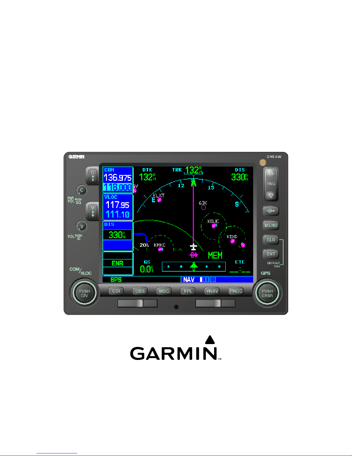
GPS 500 and GNS TM 530/530A/TAWS
(DOES NOT INCLUDE 500W (WAAS) PRODUCTS)
GNS is a trademark of Garmin Ltd. or its subsidiaries and
(GNSTM 530 Shown)
Garmin International, Inc.
190-00181-02, Revision S
February 2007

1. GENERAL DESCRIPTION
1.1 INTRODUCTION
This manual describes the physical, mechanical, and electrical characteristics and the installation
requirements for the 500 Series (GPS 500 and GNS 530) panel-mounted units. After installation of the
500 Series system, FAA Form 337 must be completed by an appropriately certificated agency to return the
aircraft to service.
Note: Throughout this document references made to GNS 530 shall equally apply to the GNS 530A
except where specifically noted. References made to the GPS 500 and GNS 530 apply equally to the
GPS 500 w/TAWS and the GNS 530 w/TAWS except where specifically noted.
1.2 EQUIPMENT DESCRIPTION
The 500 Series units are mark width (6.25” wide) units, and 4.60” high. The display is a 320 by 234 pixel
color LCD. The units include two removable data cards, one with a Jeppesen database (to be inserted in
the left most card slot), and the second being a Terrain database (to be inserted in the right most card slot).
The GPS 500 is a GPS receiver certifiable for IFR en route, terminal, and non-precision approach
operations.
The GNS 530 includes all the features of the GPS 500, and also includes IFR certified airborne VHF
communications transceiver and an IFR certified airborne VOR/Localizer and Glideslope receivers. The
(A) model is a 28 Vdc unit with a 16 Watt COM transmitter. Both units are TAWS or TERRAIN
upgradeable.
GPS signals are received by Garmin's low profile GA 56 antenna (P/N 010-10040-0X).
CAUTION
The 500 Series product lens is coated with a special anti-reflective coating which is very
sensitive to skin oils, waxes and abrasive cleaners. CLEANERS CONTAINING
AMMONIA WILL HARM THE ANTI-REFLECTIVE COATING. It is very important
to clean the lens using an eyeglass lens cleaner, which is specified as safe for antireflective coatings and a clean, lint-free cloth.
CAUTION
The use of ground-based cellular telephones while aircraft are airborne is prohibited by
FCC rules. Due to potential interference with onboard systems, the use of ground-based
cell phones while the aircraft is on the ground is subject to FAA regulation 14 CFR
§91.21.
FCC regulation 47 CFR §22.925 prohibits airborne operation of ground-based cellular
telephones installed in or carried aboard aircraft. Ground-based cellular telephones must
not be operated while aircraft are off the ground. When any aircraft leaves the ground,
all ground-based cellular telephones on board that aircraft must be turned off.
Ground-based cell phones that are on, even in a monitoring state, can disrupt GPS
performance.
500 SERIES INSTALLATION MANUAL Page 1-1
190-00181-02 Rev S

1.3 TECHNICAL SPECIFICATIONS
The conditions and tests required for TSO approval of this article are minimum performance standards. It
is the responsibility of those installing this article either on or within a specific type or class of aircraft to
determine that the aircraft installation conditions are within the TSO standards. TSO articles must have
separate approval for installation in an aircraft. The article may be installed only in compliance with 14
CFR part 43 or the applicable airworthiness requirements. For TSO compliance, see Appendix A.
1.3.1 Physical Characteristics
Bezel Height
Bezel Width
Rack Height (Dimple-to-dimple)
Rack Width
Depth Behind Panel with
Connectors (Measured from
face of aircraft panel to rear of
connector backshells)
GPS 500 Weight (Unit only)
GPS 500 Weight (Installed with
rack and connectors)
GNS 530 Weight (Unit only)
GNS 530 Weight (Installed with
rack and connectors)
1.3.2 General Specifications
Operating Temperature Range
Humidity
Altitude Range
Input Voltage Range
GPS 500 (011-00562-00, -10)
GNS 530 (011-00550-10, -30)
Input Voltage Range
GNS 530 (011-00550-00)
Input Voltage Range
GNS 530A (011-00835-00, -10)
Power Requirements
GPS 500
Power Requirements—P5001
(GNS 530 Main Connector)
Power Requirements—P5002
(COM Connector)
GNS 530 (011-00550-00)
GNS 530A (011-00835-00, -10)
Power Requirements—P5002
(COM Connector)
GNS 530 (011-00550-10)
Superflag Power Requirements
Software
Environmental Testing
4.58 in. (116 mm)
6.25 in. (159 mm)
4.60 in. (117 mm)
6.32 in. (161 mm)
11.00 in. (279 mm)
5.7 lbs. (2.59 kg)
7.2 lbs. (3.27 kg)
7.0 lbs. (3.18 kg)
8.7 lbs. (3.95 kg)
-20°C to +55°C. For more details see Environmental
Qualification Form.
95% non-condensing
-1,500 ft to 50,000 ft
11 to 33 Vdc
22 to 33 Vdc
28 Vdc
800 mA @ 27.5 Vdc (maximum)
1.6 A @ 13.8 Vdc (maximum)
1.8 A @ 27.5 Vdc (maximum)
3.6 A @ 13.75 Vdc (maximum)
15 mA @ 27.5 Vdc (not transmitting);
3.0 A @ 27.5 Vdc (transmitting)
15 mA @ 27.5 Vdc (not transmitting);
3.0 A @ 27.5 Vdc (transmitting)
15 mA @ 13.75 Vdc (not transmitting);
6.0 A @ 13.75 Vdc (transmitting)
500 mA max. Per superflag output @ 27.5 Vdc
.
1.0 A max. @ 27.5 Vdc on P5001 (Main Superflags).
1.0 A max. @ 27.5 Vdc on P5006 (VOR/LOC, G/S
Superflags).
RTCA DO-178B level C
RTCA DO-160C.
For more details see Environmental Qualification Forms.
Page 1-2 500 SERIES INSTALLATION MANUAL
Rev S 190-00181-02

1.3.3 GPS Specifications
Regulatory Compliance
Regulatory Compliance
(TAWS units only)
Acquisition Time
TSO C129a Class A(1), RTCA DO-208, JTSO C129a
ETSO C129a
a) Search-the-Sky (without almanac, without initial position or
time): 5 minutes
b) AutoLocate™ (with almanac, without initial position or time): 5
minutes
c) Cold Start (position known to 300 nm, time known to 10
minutes, with valid almanac): 45 seconds
d) Warm Start (position known to 10 nm, time known to 10
minutes, with valid almanac and ephemeris): 15 seconds
Max Velocity
Dynamics
Antenna power supply
1000 kts.
6 g
20 mA typical, 40 mA max at 4.6 VDC
1.3.4 COM Transceiver Specifications (GNS 530 Only) **
Regulatory Compliance
TSO-C37d Class 4 & 6* (3 & 5 for “A” models),TSO-C38d Class C &
E, JTSO-2C37e, JTSO-2C38e, RTCA DO-186a
ICAO Annex 10 Volume III (Part II – Voice Communications
Systems) Par. 2.3.3
Regulatory Compliance
(TAWS units only)
Audio Output
Audio Response
Audio Distortion
ETSO-2C37e, ETSO-2C38e
100 mW minimum into a 500 Ω load.
Less than 6 dB of Variation between 350 and 2500 Hz.
The distortion in the receiver audio output shall not exceed 15% at all
levels up to 100 mW.
AGC Characteristics
The audio output shall not vary by more than 6 dB when the level of
the RF input signal, modulated 30% at 1000 Hz, is varied from 5 μV
to 450,000 μV.
Sensitivity
(S+N)/N on all channels shall be greater than 6 dB when the RF level
is 2 μV (hard) modulated 30% at 1000 Hz at rated audio.
Squelch
2 μv ±6 dB for 25 kHz channels.
3 μv ±6 dB for 8.33 kHz channels.
Selectivity
6 dB BW is greater than ±8 kHz for 25 kHz channeling.
60 dB BW is less than ±25 kHz for 25 kHz channeling.
6 dB BW is greater than ±2.778 kHz for 8.33 kHz channeling.
60 dB BW is less than ±7.37 kHz for 8.33 kHz channeling.
Spurious Response
Transmitter Power
Transmitter Duty Cycle
Modulation Capability
Greater than 85 dB.
At Least 10 Watts*, 16 watts for “A” models.
Recommended 10% maximum.
The modulation shall not be less than 70% and not greater than 98%
with a standard modulator signal applied to the transmitter.
Carrier Noise Level
Frequency Stability
Demodulated Audio
Distortion
Sidetone
Shall be at least 45 dB (S+N)/N.
0.0005%
Less than 10% distortion when the transmitter is modulated at least
70%.
1.4 V
into a 500 Ω load when the transmitter is modulated at least
RMS
70%.
Demodulated Audio
Response
* C37d Class 4 & 6 may not provide suitable COM transmit range for some high-altitude aircraft.
** Specifications shown apply at nominal input voltages of 13.75 Vdc or 27.5 Vdc, as applicable, and with a nominal
50 ohm resistive load at the antenna connector.
Shall be less than 6 dB when the audio input frequency is varied from
350 to 2500 Hz.
500 SERIES INSTALLATION MANUAL Page 1-3
190-00181-02 Rev S
 Loading...