

Page 1
GNS 530
GNS 530A
Pilot’s Guide
& Ref er ence
Page 2

Page 3

This manual refl ects the operation of Main System Software version 4.0 or above. Some differences in operation may be observed when comparing the information in this manual to earlier software versions.
Garmin International, Inc., 1200 East 151st Street, Olathe, Kansas 66062 U.S.A.
Tel: 913/397.8200 Fax: 913/397.8282
Garmin (Europe) Ltd., Unit 5, The Quadrangle, Abbey Park, Romsey, Hampshire S051 9DL, U.K.
Tel: 44/1794.519944 Fax: 44/1794.519222
Garmin Corporation, No. 68, Jangshu 2nd Road, Shijr, Taipei County, Taiwan
Tel: 886/02.2642.9199 Fax: 886/02.2642.9099
INTRODUCTION
Foreword
Web Site Address: www.garmin.com
© 2001-2003 Garmin Ltd. or its subsidiaries. All rights reserved. Except as expressly provided herein, no part
Visit the Garmin website for the latest updates and
supplemental information concerning the operation
of this and other Garmin products.
of this manual may be reproduced, copied, transmitted, disseminated, downloaded or stored in any storage
medium, for any purpose without the express written permission of Garmin. Garmin hereby grants permission to download a single copy of this manual and of any revision to this manual onto a hard drive or other
electronic storage medium to be viewed for personal use, provided that such electronic or printed copy of
this manual or revision must contain the complete text of this copyright notice and provided further that any
Garmin®, AutoLocate® and PhaseTrac12® are
registered trademarks and GNS 530™ and
Spell’N’Find™ are trademarks of Garmin Ltd. or
its subsidiaries and may not be used without the
express permission of Garmin.
unauthorized commercial distribution of this manual or any revision hereto is strictly prohibited.
NavData
Information in this document is subject to change without notice. Garmin reserves the right to change or
Inc.
improve their products and to make changes in the content of this material without obligation to notify any
person or organization of such changes or improvements.
April 2003 190-00181-00 Rev. C
®
is a registered trademark of Jeppesen,
i
Page 4

INTRODUCTION
Cautions
,
CAUTION: The Global Positioning System is operated by the United States government, which is solely re spon si ble for its accuracy and maintenance. The system is subject to changes which could affect the accuracy
and performance of all GPS equipment. Although the Garmin GNS 530 is a precision electronic NAVigation
AID (NAVAID), any NAVAID can be misused or misinterpreted and therefore become unsafe.
NOTE: This device complies with Part 15 of
the FCC limits for Class B digital devices. This
equipment generates, uses, and can radiate radio
frequency energy and, if not installed and used in
accordance with the instructions, may cause harmful interference to radio com mu ni ca tions. Furthermore, there is no guarantee that in ter fer ence will
not occur in a particular in stal la tion.
If this equipment does cause harmful interference, the user is encouraged to try to correct the
interference by relocating the equipment or connecting the equipment to a different circuit than the
affected equipment. Consult an authorized dealer
or other qualifi ed avionics technician for additional
help if these remedies do not correct the problem.
Operation of this device is subject to the following conditions: (1) This device may not cause
harmful interference, and (2) this device must
accept any interference received, including interference that may cause undesired operation.
,
,
,
,
,
CAUTION: Use the GNS 530 at your own risk. To reduce the risk of unsafe operation, carefully review and
un der stand all aspects of this Owner’s Manual and the Flight Manual Sup ple ment, and thor ough ly practice
basic operation prior to actual use. When in actual use, carefully compare in di ca tions from the GNS 530 to
all available navigation sources, including the information from other NAVAIDS, visual sightings, charts, etc.
For safety, always resolve any dis crep an cies before continuing navigation.
WARNING: The altitude calculated by the GNS 530 is geometric height above mean sea level and could vary
sig nifi cant ly from altitude displayed by pressure altimeters in aircraft. GPS accuracy may be degraded by the
U.S. Department of De fense-imposed Selective Availability (SA) program. With “SA” on, GPS altitude may be
in error by several hundred feet. Never use GPS altitude for vertical navigation.
WARNING: The Jeppesen database incorporated in the GNS 530 must be updated reg u lar ly in order to
ensure that its information is current. Updates are released every 28 days. A database in for ma tion packet is
included in your GNS 530 package. Pilots using an out-of-date database do so entirely at their own risk!
CAUTION: GPS receivers operate by receiving and decoding very low power radio signals broadcast by
sat el lites. It is possible that in some situations other radio equipment or electronic equipment used in close
proximity to a GPS receiver may create electromagnetic interference (EMI) which may affect the ability of the
GPS receiver to receive and decode the satellite signals. In such event, the interference may be reduced or
eliminated by switching off the source of interference or moving the GPS receiver away from it.
CAUTION: The Garmin GNS 530 does not contain any user-serviceable parts. Repairs should only be made
by an authorized Garmin service center. Unauthorized repairs or modifi cations could void your warranty and
authority to operate this device under FCC Part 15 regulations.
ii
Page 5

Congratulations on choosing the world’s fi nest panel-mounted IFR navigation/com munication system! The
GNS 530 represents Garmin’s continued commitment to providing you with the most advanced tech nology
available today — in an accurate, easy-to-use design suitable for all of your fl ying needs.
INTRODUCTION
Accessories and Packing List
)
Unless otherwise specifi ed within this manual, the term "GNS 530" applies to both the GNS 530
and the GNS 530A models. Please, note that the difference between these two models is indicated
under "VHF COM Performance" in the Specifi cations section of this manual (see Appendix B).
Before installing and getting started with your new system, please ensure that your package includes the
following items. If any parts are missing or are damaged, please contact your Garmin dealer.
Standard Package:
To obtain accessories for your GNS 530, please
contact your Garmin dealer.
• GNS 530 Unit & NavData® Card
• GPS Antenna
• Installation Rack & Connectors
• Pilot’s Guide & Quick Reference Guide
• 400/500 Series Display Interfaces Pilot’s Guide Addendum
• GNS 530 Simulator Interactive Training CD-ROM
• Database Subscription Packet
• Warranty Registration Card
Your Garmin dealer will perform the installation and confi guration of your new GNS 530. After in stallation, the NavData® card will already be installed into the correct slot on the front of the unit (see Appendix
A). The GNS 530 will be secured in the installation rack with the proper wiring con nections. Have your
dealer answer any questions you may have about the installation — such as location of antennas or any con-
Help us better support you by completing our
on-line registration form today! Registration
ensures that you will be notifi ed of product updates
and new products and provides lost or stolen
unit tracking. Please, have the serial number
of your GNS 530 handy, connect to our website
(www.garmin.com) and look for our Product
Registration link on the home page.
The GNS 530 display lens is coated with a special
anti-refl ective coating which is very sensitive to
skin oils, waxes and abrasive cleaners. It is very
important to clean the lens using an eyeglass lens
cleaner which is specifi ed as safe for anti-refl ective
coatings (one suitable product is Wal-Mart® Lens
Cleaner) and a clean, lint-free cloth.
nections to other equipment in the panel.
iii
Page 6

INTRODUCTION
Warranty
Garmin is fully committed to your satisfaction as
a customer. If you have any questions regarding
the GNS 530, please contact our customer service
department at:
Garmin International, Inc.
1200 East 151st Street
Olathe, KS 66062-3426 U.S.A.
Phone: (913) 397-8200
Fax: (913) 397-8282
LIMITED WARRANTY
This Garmin product is warranted to be free from defects in materials or workmanship for one year from
the date of purchase. Within this period, Garmin will at its sole option, repair or replace any components
that fail in normal use. Such repairs or replacement will be made at no charge to the customer for parts or
labor, provided that the customer shall be responsible for any transportation cost. This warranty does not
cover failures due to abuse, misuse, accident or unauthorized alteration or repairs.
THE WARRANTIES AND REMEDIES CONTAINED HEREIN ARE EXCLUSIVE AND IN LIEU OF ALL
OTHER WARRANTIES EXPRESS OR IMPLIED OR STATUTORY, INCLUDING ANY LIABILITY ARISING
UNDER ANY WARRANTY OF MERCHANTABILITY OR FITNESS FOR A PARTICULAR PURPOSE,
STATUTORY OR OTHERWISE. THIS WARRANTY GIVES YOU SPECIFIC LEGAL RIGHTS, WHICH MAY
VARY FROM STATE TO STATE.
IN NO EVENT SHALL GARMIN BE LIABLE FOR ANY INCIDENTAL, SPECIAL, INDIRECT OR
CONSEQUENTIAL DAMAGES, WHETHER RESULTING FROM THE USE, MISUSE, OR INABILITY TO
USE THIS PRODUCT OR FROM DEFECTS IN THE PRODUCT. Some states do not allow the exclusion of
incidental or consequential damages, so the above limitations may not apply to you.
Garmin retains the exclusive right to repair or replace the unit or software or offer a full refund of the
purchase price at its sole discretion. SUCH REMEDY SHALL BE YOUR SOLE AND EXCLUSIVE REMEDY
FOR ANY BREACH OF WARRANTY.
To obtain warranty service, contact your local Garmin Authorized Service Center. For assistance in
locating a Service Center near you, call Garmin Customer Service at the number listed on the right.
Products sold through online auctions are not eligible for rebates or other special offers from Garmin.
Online auction confi rmations are not accepted for warranty verifi cation. To obtain warranty service, an
original or copy of the sales receipt from the original retailer is required. Garmin will not replace missing
components from any package purchased through an online auction.
iv
Page 7

PART ONE: INTRODUCTION
Foreword........................................................................................................................................ i
Cautions........................................................................................................................................ ii
Accessories / Packing List ............................................................................................................. iii
Warranty ...................................................................................................................................... iv
Table of Contents ...................................................................................................................... v-vi
PART TWO: TAKEOFF TOUR
Key and Knob Functions ............................................................................................................1-3
Power On ...................................................................................................................................4-6
Acquiring Satellites / Viewing Messages .........................................................................................7
Selecting COM/NAV Frequencies ..................................................................................................8
Map Page....................................................................................................................................... 9
Page Groups ...........................................................................................................................10-11
Direct-To Navigation ................................................................................................................... 12
Default NAV Page ........................................................................................................................ 13
NAVCOM Page............................................................................................................................14
IFR Procedures............................................................................................................................ 15
Nearest Airports .....................................................................................................................16-17
Special-use/Controlled Airspace ..................................................................................................18
Flight Plans ............................................................................................................................19-20
PART THREE: REFERENCE
Section 1: Communicating with the GNS 530 ........................................................................21-26
COM and VLOC frequencies; active and standby frequencies
Section 2: NAV Pages (GPS navigation pages).........................................................................27-43
INTRODUCTION
Table of Contents
For information or help on a specifi c topic, please
use the Index section.
Using page groups and selecting the desired page; using the default NAV and map pages
v
Page 8

INTRODUCTION
Table of Contents
To quickly and easily locate information on specifi c
tasks, please refer to the Index on page 184.
Section 3: Direct-to Navigation...............................................................................................44-48
Using the direct-to key
Section 4: Flight Plans (FPL key and FPL page group) ...........................................................49-60
Creating and using fl ight plans; retrieving and editing stored fl ight plans
Section 5: Approaches, Departures & Arrivals (PROC key)....................................................61-87
Selecting and fl ying non-precision/precision approaches; selecting and using departures (SIDs)
and arrivals (STARs)
Section 6: WPT Pages (Waypoint/database information).......................................................88-112
Finding and viewing airport location, runway and frequency data; fi nding and viewing navaid
information; creating user-defi ned waypoints
Section 7: NRST Pages (Nearest airports, etc.) ....................................................................113-124
Viewing nearest listings for airports, navaids and airspaces; displaying frequencies for nearest
fl ight service (FSS) and center
Section 8: VLOC (VOR/Localizer/Glideslope) Receiver Operations .....................................125-128
Section 9: AUX Pages (Flight Planning and Unit Settings) ..................................................129-154
Section 10: Vertical Navigation (VNAV)..............................................................................155-157
Section 11: Fault Detection and Exclusion (FDE) Interface.................................................158-160
Section 12: Messages, Abbreviations & Navigation Terminology ........................................161-173
Appendix A: NavData® Card Use .............................................................................................174
Appendix B: Specifi cations ........................................................................................................ 175
Appendix C: Map Datums ..................................................................................................176-177
Appendix D: Troubleshooting Q & A .................................................................................178-183
Appendix E: Index .............................................................................................................184-188
vi
Page 9
The GNS 530 is designed to make operation as simple as possible. The descriptions on the next three
pages provide a general overview of the primary function(s) for each key and knob. This Takeoff Tour section
is intended to provide a brief overview of the pri mary functions of your GNS 530. Experiment with the unit
and refer to the reference sec tions for more information.
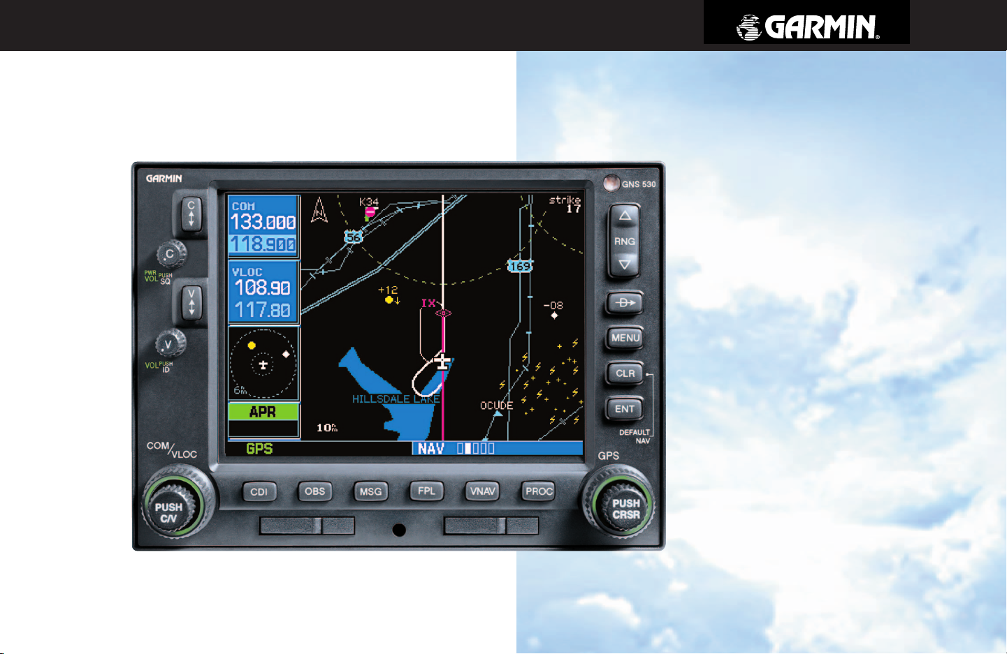
Left-hand Keys and Knobs
TAKEOFF TOUR
Key and Knob Functions
k
j
y
v
W
V
The COM power/volume knob controls unit power and communications radio volume.
Press momentarily to disable automatic squelch control.
The VLOC volume knob controls audio volume for the selected VOR/ Localizer frequency.
Press momentarily to enable/disable the ident tone.
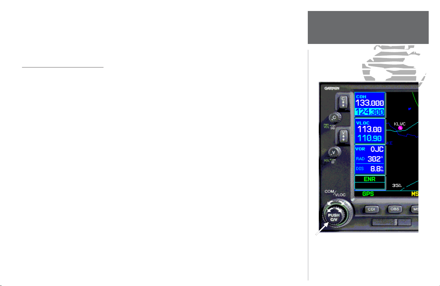
The large left knob (COM/VLOC) is used to tune the megahertz (MHz) value of the
standby frequency for the communications transceiver (COM) or the VOR/Localizer receiver,
whichever is currently selected by the tuning cursor.
The small left knob (PUSH C/V) is used to tune the kilohertz (kHz) value of the standby
frequency for the communications transceiver (COM) or the VLOC receiver, whichever is
currently selected by the tuning cursor. Press this knob momentarily to toggle the tuning
cursor between the COM and VLOC frequency fi elds.
The COM fl ip-fl op key is used the swap the active and standby COM frequencies. Press
and hold to select emergency channel (121.500 MHz).
The VLOC fl ip-fl op key is used to swap the active and standby VLOC frequencies (i.e.,
make the selected standby frequency active).
The large and small left knobs allow you to tune
the desired COM or VLOC frequency.
1
Page 10
TAKEOFF TOUR
Key and Knob Functions
Right-hand Keys and Knobs
RNG
D
m
c
The range key allows you to select the desired map scale. Use the up arrow side of the key
to zoom out to a larger area, or the down arrow side to zoom into a smaller area.
The direct-to key provides access to the direct-to function, which allows you to enter a des-
tination waypoint and establishes a direct course to the selected destination. See Section 3.
The menu key displays a context-sensitive list of options. This options list allows you to
access additional features or make settings changes which relate to the currently displayed
page.
The clear key is used to erase information or cancel an entry. Press and hold this key to im-
mediately display the Default Navigation Page (see pages 10 and 28), regardless of the page
that is currently displayed.
Data is entered using the large and small right
knobs. Experiment with them to become effi cient
at entering data. This greatly reduces the amount
of time spent operating the GNS 530 in fl ight.
2
E
t
r
The enter key is used to approve an operation or complete data entry. It is also used to
confi rm information, such as the Database Page during power on.
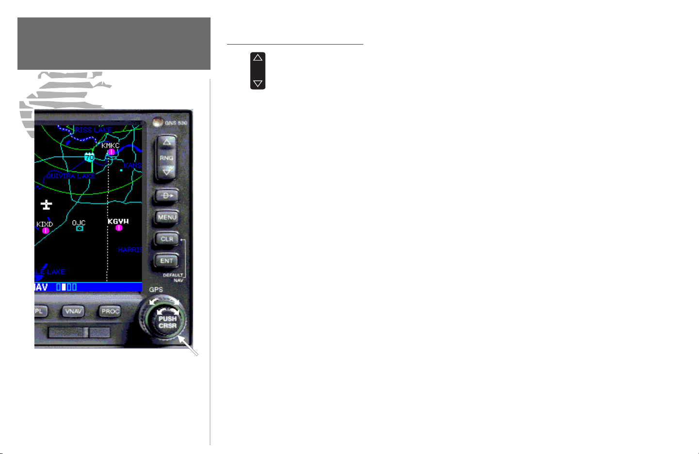
The large right knob (GPS) is used to select between the various page groups: NAV, WPT,
AUX or NRST. With the on-screen cursor enabled, the large right knob allows you to move
the cursor about the page.
The small right knob (PUSH CRSR) is used to select between the various pages within one
of the groups listed above. Press this knob momentarily to display the on-screen cursor. The
cursor allows you to enter data and/or make a selection from a list of options.
Page 11
Bottom Row Keys
TAKEOFF TOUR
Key and Knob Functions
C
O
M
F
VNAV
P
The CDI key is used to toggle the navigation source (GPS or VLOC) which provides output
to an external HSI or CDI.
The OBS key is used to select manual or automatic sequencing of waypoints. Pressing this
key selects OBS mode, which retains the current “active to” waypoint as your navigation
reference even after passing the waypoint (i.e., prevents sequencing to the next waypoint).
Pressing the OBS key again returns to normal op eration, with automatic sequencing of
waypoints. Whenever OBS mode is selected, you may set the desired course to/from a waypoint using the OBS Page, or an external OBS selector on your HSI or CDI.
The message key is used to view system messages and to alert you to important warnings and
requirements. See Sections 12 and 9 for more information on messages and unit settings.
The fl ight plan key allows you to create, edit, activate and invert fl ight plans, as well as
access approaches, departures and arrivals. A closest point to fl ight plan feature is also available from the fl ight plan key. See Section 4 for more information on fl ight plans.
The vertical navigation key allows you to create a three-dimensional profi le which guides
you to a fi nal (target) altitude at a specifi ed location. See Section 10.
The procedures key allows you to select approaches, departures and arrivals from your
fl ight plan. When using a fl ight plan, available procedures for your de parture and/or arrival
airport are offered automatically. Otherwise, you may select the desired airport, then the
desired procedure.
Whenever the GNS 530 is dis play ing a list of
information that is too long for the display screen,
a scroll bar appears along the right-hand side of
the display. The scroll bar graphically in di cates the
number of additional items available within the
se lect ed category.
Simply press the small right knob to activate the
cursor and rotate the large right knob to scroll
through the list.
3
Page 12

TAKEOFF TOUR
Power On
The Welcome Page appears when the GNS 530
is powered on. Dur ing the time this screen is dis played, the GNS 530 performs a self test to ensure
proper op er a tion.
The Garmin GNS 530 offers you accurate navigational data and communication ca pability, along with
non-precision and precision approach certifi cation in the IFR environment. The Takeoff Tour is designed
to familiarize you with the basic operation of the GNS 530 — in cluding powering up the unit, changing
frequencies, entering data, performing a simple direct-to, selecting IFR procedures and provides a limited
introduction to using fl ight plans. In ad dition, this section briefl y covers the default navigation, map and
frequency pages available as part of the NAV page group. These pages are used for most of your in-fl ight
navigation.
The Takeoff Tour assumes that the unit and antennas have been properly installed and you have not
changed any of the GNS 530’s default settings. If you have changed any of the factory default settings (position format, units of measure, selectable fi elds, etc.), the pictures shown here may not exactly match what
you see on your GNS 530. Prior to using your GNS 530 for the fi rst time, we recommend that you taxi to a
location that is well away from build ings and other aircraft so the unit can collect satellite data without interruption.
Powering up the GNS 530
The GNS 530’s power and COM volume are controlled using the COM power/volume knob at the top
left corner of the unit. Rotating it clockwise turns unit power on and increases the COM radio volume. After
turning the unit on, a Welcome Page is displayed while the unit performs a self test, followed by a Land Data
Page.
The Database Confi rmation Page appears next and shows the current database information on the NavData card (with the valid operating dates, cycle number and database type indicated). The database is updated
every 28 days and must be current for approved instrument approach operations. Information on database
subscriptions is available inside your GNS 530 package.
The Database Page shows the effective and
expiration dates of the Jeppesen database on the
NavData Card.
4
To acknowledge the database information, press the ENT key.
Page 13
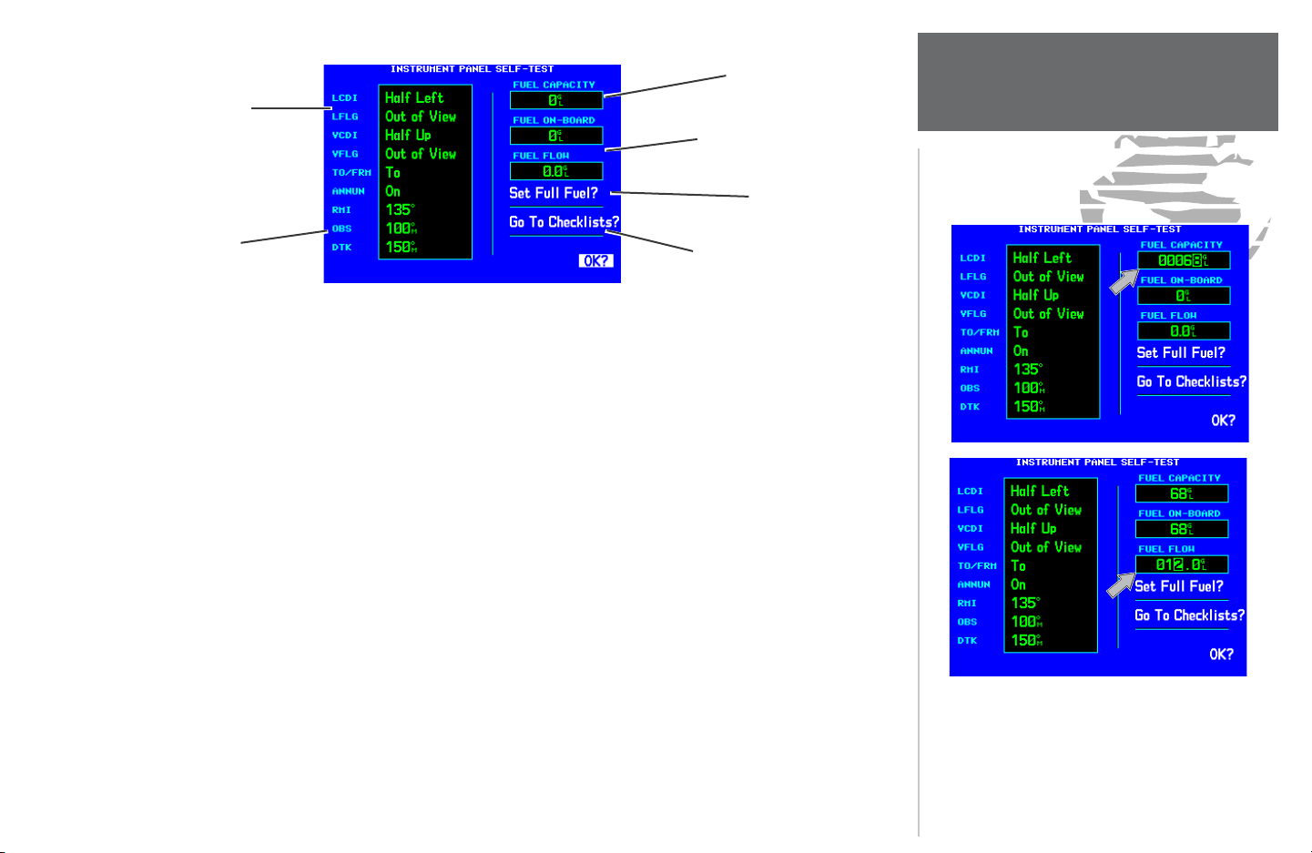
Fuel Capacity is
Check CDI/HSI,
RMI and other in-
struments to verify
these indications.
Should match
current OBS course
selection
entered manually
Fuel on board and fuel fl ow are
provided by sensors, if installed
Select to Set Fuel Level
to Full Capacity
Select to display
Checklists Page
Once the database has been acknowledged, the Instrument Panel Self-Test Page appears. To ensure that
your GNS 530 and any connected instruments are working properly, check for the following indications on
your CDI/HSI, RMI, external annunciators and other connected instruments:
• Course deviation - half left / no fl ag • Glideslope - half up / no fl ag
• TO/FROM fl ag - TO • Time to destination - 4 minutes
• Bearing to destination - 135° • Desired track - 149.5°
• Distance to dest. - 10.0 nautical miles • Ground speed - 150 knots
• All external annunciators (if installed) - on
The Instrument Panel Self-Test Page indicates the currently selected OBS course, fuel capacity (CAP), fuel
on board (FOB) and fuel fl ow (FF). The fuel capacity is entered manually. Fuel on board and fuel fl ow may
be man ually entered if your installation does not include connection to sensors which au tomatically provide
these fi gures.
To enter fuel capacity, fuel on board or fuel fl ow fi gures (if not provided by sensors):
1. Rotate the large right knob to select the “CAP”, “FOB” or “FF” fi eld.
2. Rotate the small and large right knobs to enter the desired fi gure, then press ENT.
TAKEOFF TOUR
Instrument Panel Self-Test
Enter the fuel capacity, fuel on board or fuel fl ow
fi gures directly onto the appropriate fi eld of the
Instrument Panel Self-Test Page. Fuel on board
and fuel fl ow are automatically provided if your
installation includes connection to external sensors.
5
Page 14

TAKEOFF TOUR
Fuel On Board and Checklists
Select “Set Full Fuel?” to set fuel on board (FOB) to
full capacity.
The Instrument Panel Self-Test Page includes selections to set fuel on board (FOB) to full capacity and
access the Checklists Page. This allows you to quickly set fuel to full limits and display any check lists you’ve
entered, such as start up or takeoff checklists.
To set fuel on board to full (if not provided by sensor):
1. Rotate the large right knob to highlight “Set Full Fuel?”.
2. Press ENT and verify that fuel on board (FOB) now matches the fuel capacity (CAP) fi gure. Fuel on board is
now reduced, over time, based on the fuel fl ow (FF) fi gure.
To view the checklists page:
1. Rotate the large right knob to highlight “Go To Checklists?” and press ENT.
2. Rotate the large right knob to select the desired checklist, then follow the steps on page 140 to execute
each step in the selected checklist.
3. Once you complete the desired checklist(s), press the small right knob to return to the Checklists Page. Press
the small right knob again to return to normal operation on the Satellite Status or Map pages.
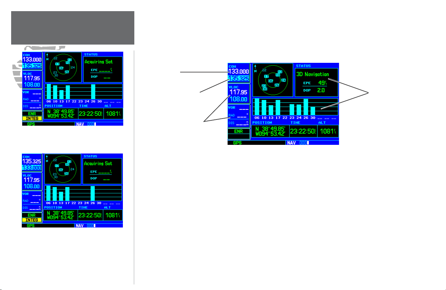
Once you’ve verifi ed instrument operation with the Instrument Panel Self-Test Page displayed, rotate the large right knob to highlight “OK?” and press the ENT key.
The Satellite Status Page appears as the GNS 530 begins to collect satellite information. An ‘Acquiring’
status is displayed on the Satellite Status Page and the signal strength of any satellites received appears as “bar
graph” readings. This is a good indication that you are receiving signals and that a position fi x is determined.
Following the fi rst-time use of your GNS 530, the time required for a position fi x varies — usually from one
to two minutes.
Select “Go To Checklists?” to display the Checklist
Page and any available checklists. The GNS 530
can hold up to nine checklists with up to 30 entries
in each checklist.
6
If the unit can only obtain enough satellites for 2D navigation (no altitude), the unit uses the altitude
provided by your altitude encoder (if one is connected).
Page 15
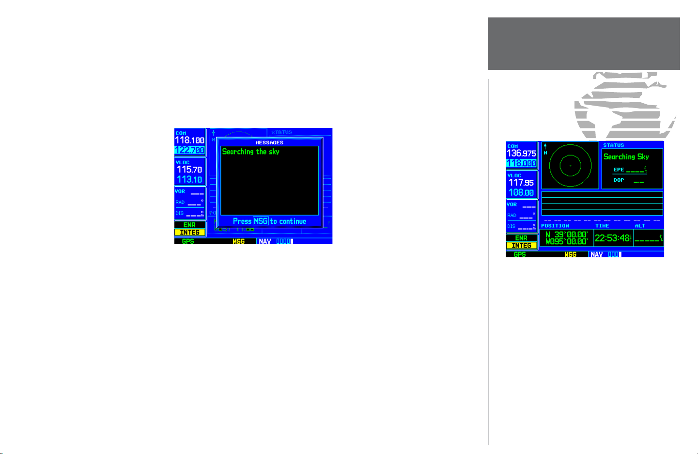
If the GNS 530 has not been operated for a period of six months or more, it may have to ‘Search the Sky’
to collect new data. This means the unit is acquiring satellite data to es tablish almanac and satellite orbit
information, which can take 5 to 10 minutes. The Satellite Status Page displays a ‘Searching Sky’ status, and
the message annunciator (MSG) above the MSG key also fl ashes to alert you of a system mes sage, ‘Search ing
the Sky’.
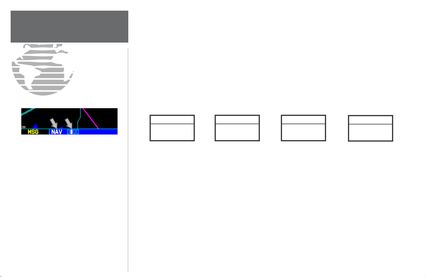
To view a system message, press MSG.
MESSAGE PAGE
The Message Page appears and displays the status or warning information applicable to the re ceiver’s current operating condition.
To return to the previous page after viewing a message, press MSG again.
TAKEOFF TOUR
Acquiring Satellites / Mes sages
The Satellite Status Page shows the ID numbers
for the satellites and the relative signal strength of
each satellite received (as a “bar graph” reading).
‘Searching Sky’ indicates that satellite almanac
data is not available or has expired (if the unit
hasn’t been used for six months or more). The data
is recollected from the fi rst available satellite.
The ‘INTEG’ annunciator (bot tom left corner of
the screen) indicates that satellite coverage is insuffi cient to pass built-in integrity monitoring tests. In
the example above, not enough satellites are being
received to determine a position.
7
Page 16
TAKEOFF TOUR
Selecting COM/NAV Fre quencies
While the GNS 530 is acquiring a position, let’s take a minute to dial in the active and stand by fre quencies
you’ll be using for the fi rst phase of your fl ight. The GNS 530’s display is divided into separate ‘windows’ (or screen
areas), including a COM window, VLOC window (by default with VOR ident/radial, but selectable for other data
— including a traffi c display) and a GPS win dow which occupies the right 3/4 of the display.
COM Window:
Active Frequency
Satellite Status Page with cursor active in COM
window.
To switch the active and standby frequencies, press
the COM fl ip-fl op key. Switching the active and
standby frequencies does not remove the cursor
from the COM window.
8
COM Window:
Standby Frequency
(with tuning
VLOC Tuning Window and
VLOC Ident Window
(Ident Window is user-selectable)
GPS Window:
(right 3/4 of display)
Pushing the small left knob moves the tuning cursor back-and-forth between the COM and VLOC
fre quency windows. To select the active frequency, you must fi rst enter the frequency in the standby fi eld, and
use the COM (or VLOC) fl ip-fl op key to move it to the active fi eld.
To change the standby communication frequency:
1. Press the small left knob, if needed, to move the tuning cursor to the COM window.
2. Rotate the large left knob to select the MHz, and the small left knob to select the kHz of the desired
frequency.
To place the standby communication frequency in the active fi eld, press the COM fl ip-fl op key.
Once you’ve entered the active frequency, simply repeat steps 1 and 2, above, to enter the standby frequency. After both communication frequencies have been entered, you may elect to keep the COM window
‘hot’ by leaving the cursor on the standby frequency, or move the cursor to the VLOC window by pressing the
small left knob. NOTE: When selecting VLOC frequencies, the tuning cursor automatically returns to the
COM window after 30 seconds of inactivity.
Page 17
To change the standby VLOC frequency:
1. Press the small left knob, if needed, to activate the tuning cursor in the VLOC window.
2. Rotate the large left knob to select the MHz, and the small left knob to select the kHz of the desired
frequency.
To place the standby frequency in the active fi eld, press the VLOC fl ip-fl op key.
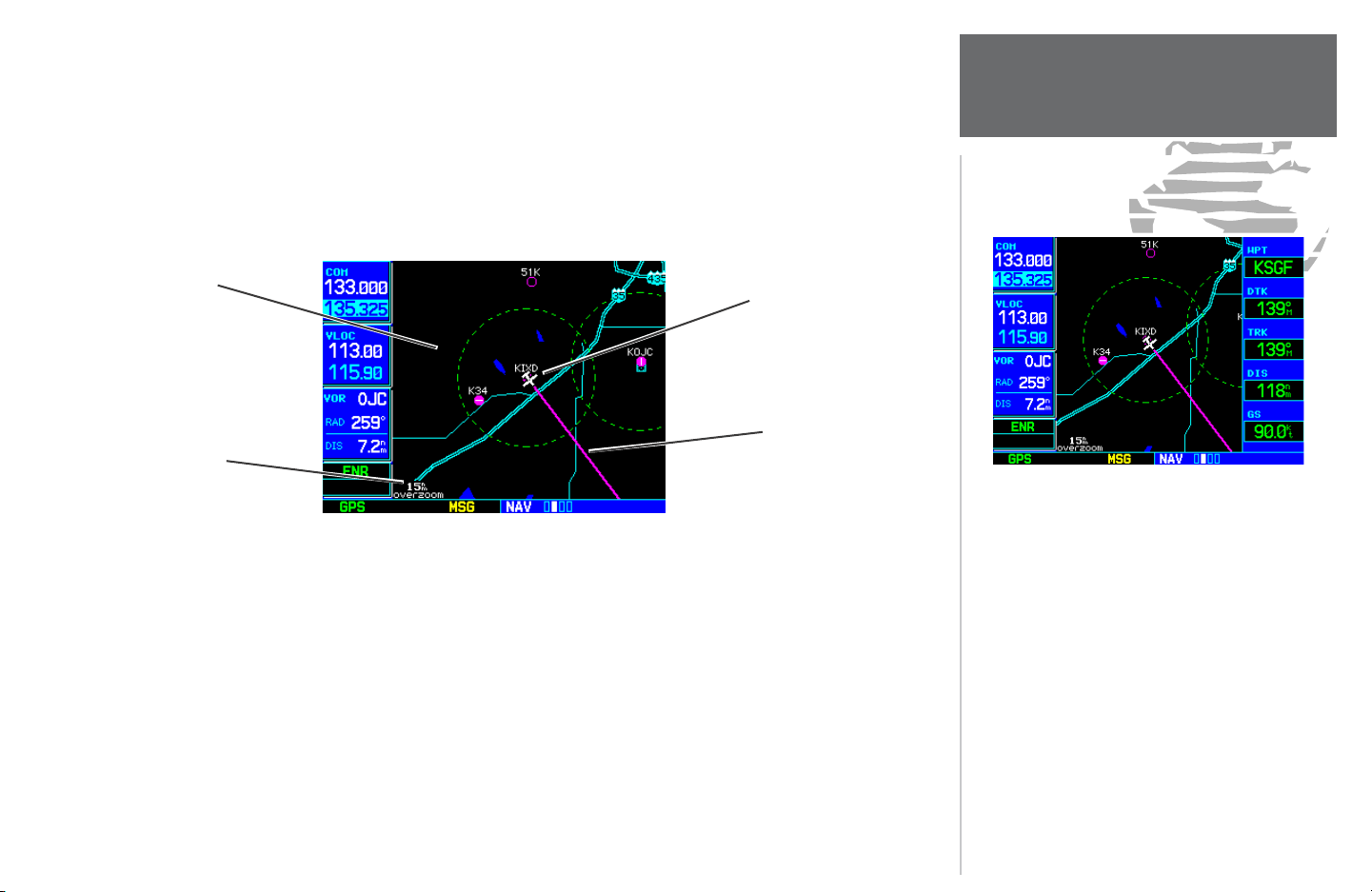
After the GNS 530 acquires satellites and computes a position, the Map Page appears au tomatically.
TAKEOFF TOUR
Map Page
Map Display
Present Position
Desired Track
Map Scale
MAP PAGE
The Map Page displays your present position (using an airplane symbol) relative to nearby airports, VORs,
NDBs, intersections, user waypoints and airspace boundaries — and your route displayed as a solid line. The
current map scale is indicated in the lower left corner and adjustable using the RNG key.
To adjust the map scale:
1. Press the up arrow on the RNG key to zoom out to a larger area. OR,
2. Press the down arrow on the RNG key to zoom in to a smaller area.
By adding data fi elds along the right-hand side, the
Map Page can combine a mov ing map display and
navigation data for complete situational aware ness.
Map setup pages are provided to add these data
fi elds and to designate the max i mum scale at which
each map feature appears. These set tings provide
an automatic decluttering of the map (based upon
your preferences) as you adjust the scale.
While viewing the map page, you can quickly
declutter and remove many of the background map
details by pressing the CLR key (repeatedly) until
the desired detail is depicted.
To change the map scale, use the RNG key.
9
Page 18
TAKEOFF TOUR
Page Groups
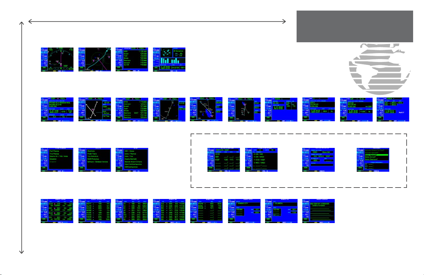
The map page is one of four pages available under the NAV group*:
• Default NAV Page • Map Page • NAVCOM Page • Satellite Status Page
To select the desired NAV page, rotate the small right knob until the desired page is displayed.
If you are currently viewing a page which is not part of the NAV group, you can quickly return to the NAV
group using the CLR key.
To select the NAV group and display the Default NAV Page, press and hold CLR.
In addition to the group of NAV pages, additional groups of pages are available for waypoint in formation
(WPT), auxiliary (AUX) functions such as fl ight planning or unit settings, and listings for nearest (NRST)
airports or other facilities.
The bottom right corner of the screen indicates the
page group that is currently being dis played (e.g.,
NAV or NRST), the number of screens available
within that group (indicated by square icons) and
the placement of the current screen within that
group (indicated by a highlighted square icon). To
select a different page within the group, rotate the
small right knob.
* Five NAV pages are available when the GNS 530
installation includes connection to traffi c and/or
weather information sources. See 400/500 Series
Display Interfaces Pilot's Guide Addendum.
10
NAV
4 available pages*
(see pg. 27)
WPT
10 available pages
(see list pg. 88)
AUX
3 available pages
(see list pg. 131)
NRST
8 available pages
(see list pg. 113)
To select the desired page group, rotate the large right knob until a page from the desired
group is displayed.
To select the desired page within the group, rotate the small right knob until the desired
page is displayed.
The following page depicts the organization of the main page groups. Additionally, page groups for fl ight
plans, procedures and vertical navigation are available by pressing the key corresponding to the desired function (FPL, PROC or VNAV). Selecting one of these stand-alone page groups, in effect, exits the main page
groups and displays a page for the desired function. When pressing the same function key a second time, the
GNS 530 returns to the main page group and the previously displayed page.
To select a stand-alone page group, press the corresponding key (FPL, PROC or VNAV).
To return to the previous page from the main page groups, press the same stand-alone
page group key (FPL, PROC or VNAV) a second time.
Page 19
NAV Group
Default NAV
WPT Group
(Small right knob to select pages within the group)
NOTE: Five NAV pages are available when the GNS 530 installation includes connection to traffi c and/or weather information
sources. See 400/500 Series Display Interfaces Pilot's Guide
Addendum.
NAVCOMMap
Satellite Status
TAKEOFF TOUR
Page Groups
Airport Location
AUX Group
Flight Planning
Airport FrequencyAirport Runway
Airport Approach
Airport Arrival
FPL Group
SetupUtility
Active Flight Plan
IntersectionAirport Departure
NDBs
VNAV PROC
Vertical NavigationFlight Plan Catalog
VOR
Procedures
(Large right knob to change page groups)
NRST Group
Nearest Airport
Nearest NDBNearest Intersection
Nearest VOR
Selection of any main page is performed using the large and small right knobs. The large right knob selects the page group: NAV, WPT, AUX or
NRST. The small right knob selects the desired page within a group. To quickly select the Default NAV page, Press and hold CLR.
Nearest User Wpt
Nearest FSSNearest Center
Nearest Airspace
User Waypoint
11
Page 20
TAKEOFF TOUR
Direct-To Navigation
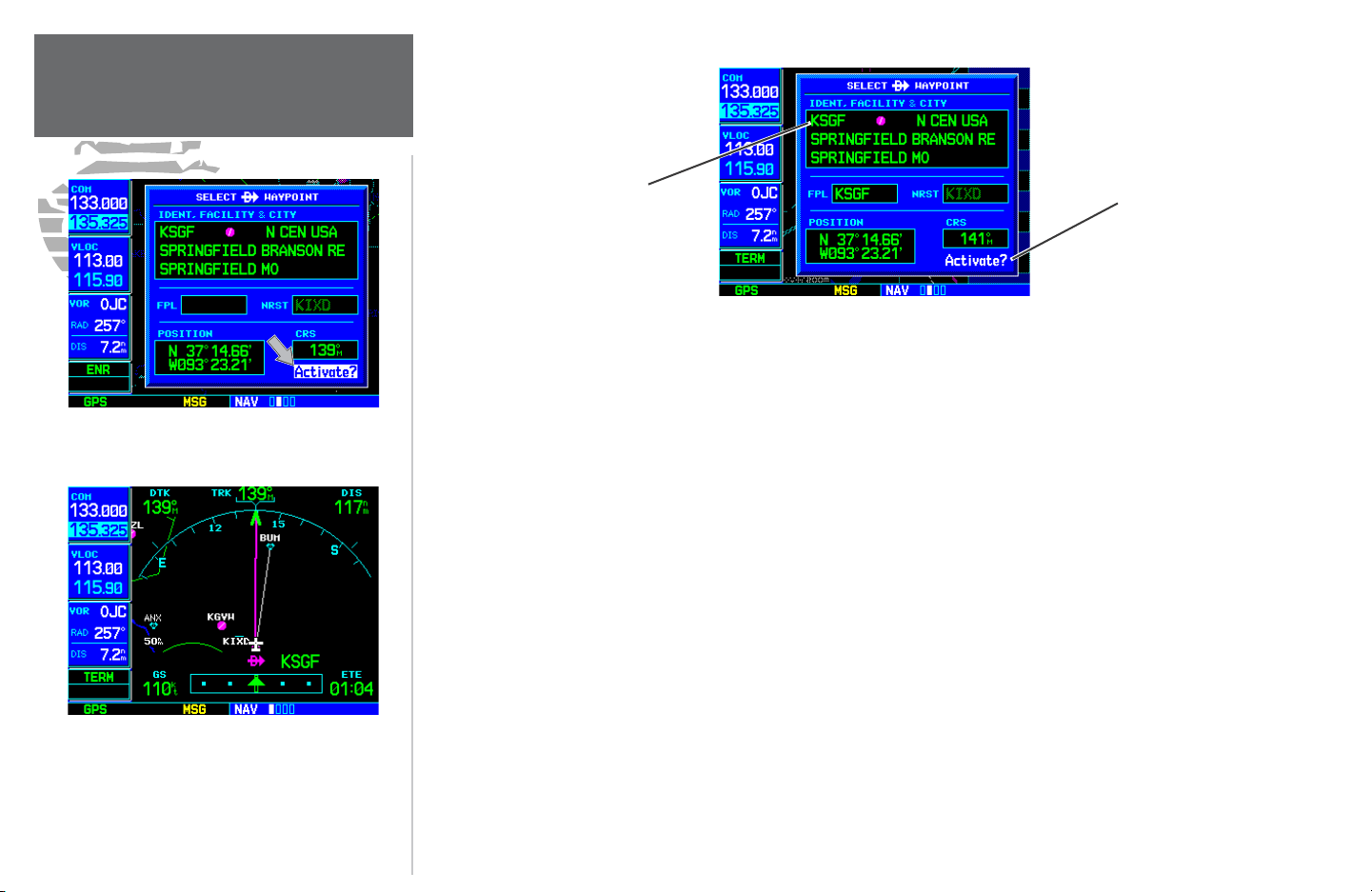
Confi rm the selected direct-to destination by highlighting “Activate?” and pressing ENT.
Once a direct-to destination is selected, press and
hold CLR to display the Default NAV Page.
Destination Waypoint
Identifi er Field
SELECT DIRECT-TO WAYPOINT PAGE
“Activate?”
Function Field
The GNS 530 can use direct point-to-point navigation to guide you from takeoff to touch down, even in
the IFR environment. Once a destination is selected, the unit provides speed, course and distance data based
upon a direct course from your present position to your destination. A destination can be selected from any
page with the direct-to key.
To select a direct-to destination:
1. Press the direct-to key. The Select Direct-to Waypoint Page appears with the destination fi eld highlighted.
2. Rotate the small right knob to enter the fi rst letter of the destination waypoint identifi er. The destination
waypoint may be an airport, VOR, NDB, intersection or user waypoint, as long as it is in the database or stored
in memory as a user waypoint.
3. Rotate the large right knob to the right to move the cursor to the next character po si tion.
4. Repeat steps 2 and 3 to spell out the rest of the waypoint identifi er.
5. Press ENT to confi rm the identifi er. The “Activate?” function fi eld is highlighted.
6. Press ENT to activate a direct-to course to the selected destination.
12
Page 21
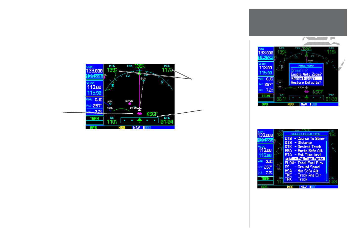
During most fl ights, the Default NAV, Map and NAVCOM pages are the primary pages used for navigation.
The Default NAV Page displays a “look ahead” map, graphic course deviation indicator (CDI), the active leg
of your fl ight plan (as defi ned by the current “from” and “to” waypoints), and four user-selectable data fi elds.
The default settings for these fi elds are dis tance to waypoint (DIS), desired track (DTK), ground speed (GS)
and estimated time en route (ETE). See Section 12 for definitions of these navigation terms. The Default NAV
Page is selected using the steps described on page 10.
User-selectable Data Fields
(all four corners)
TAKEOFF TOUR
Default NAV Page
Active Leg of Flight Plan,
or Direct-to Destination
DEFAULT NAV PAGE
Course Deviation
Indicator (CDI)
From the Default NAV Page, simply rotate the small right knob to display the Map Page (see page 9) and
again to display the NAVCOM Page. The NAVCOM Page displays the available frequencies (com munication
and navigation) for the departure airport, any en-route airports which are included in your fl ight plan, and
the fi nal destination airport. When using the direct-to function, frequencies are listed for the airport nearest to
your starting po sition and the destination airport.
The data fi elds on the Default NAV Page may be
custom-tailored to your preferences. A menu selection is provided to “Change Fields?”.
The large right knob is used to select the data
fi eld you wish to change. Then use the small right
knob to display a list of data options and select the
desired data item.
13
Page 22
TAKEOFF TOUR
NAVCOM Page
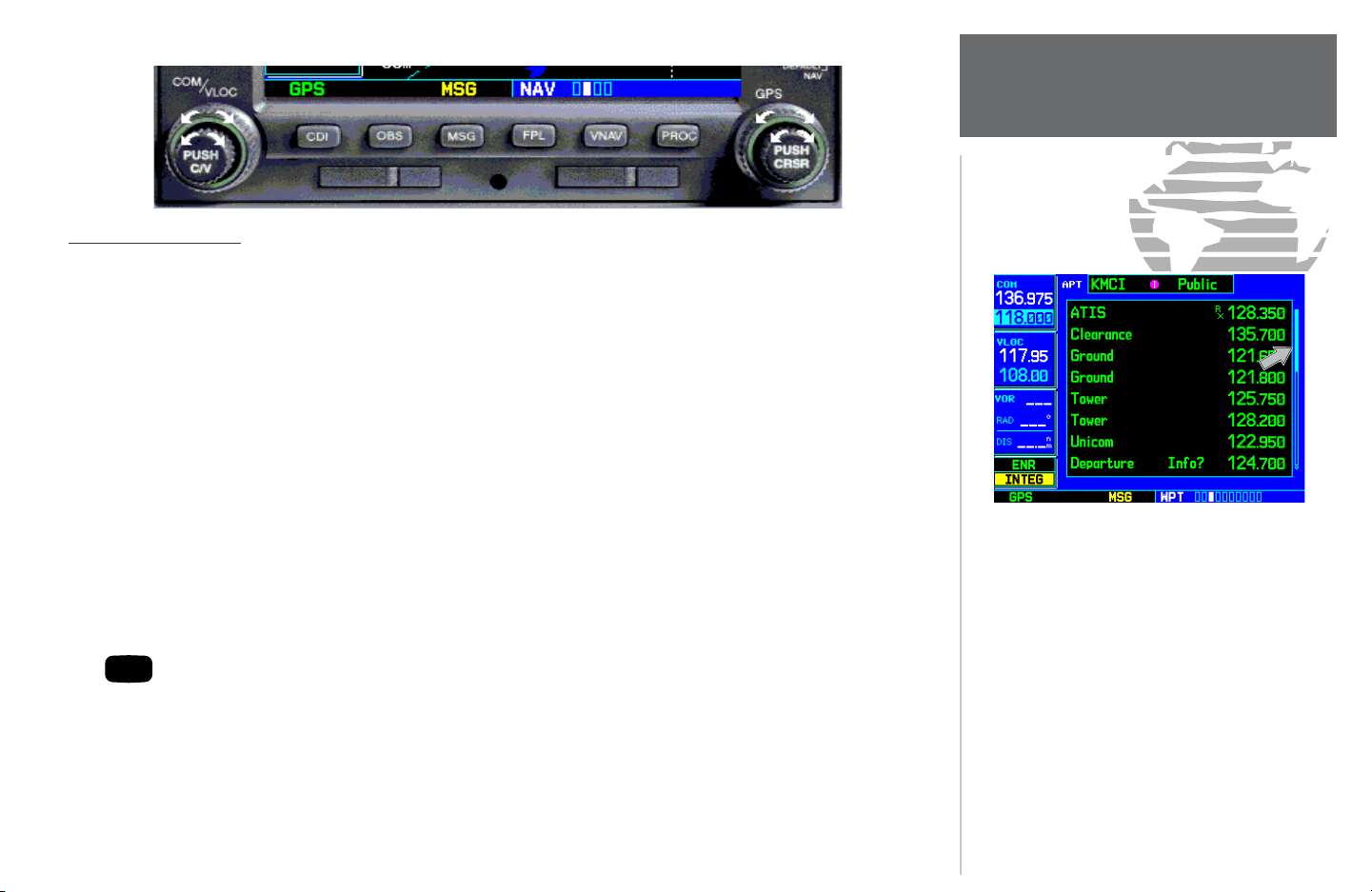
To display the frequency list for the desired fl ight plan or direct-to airport:
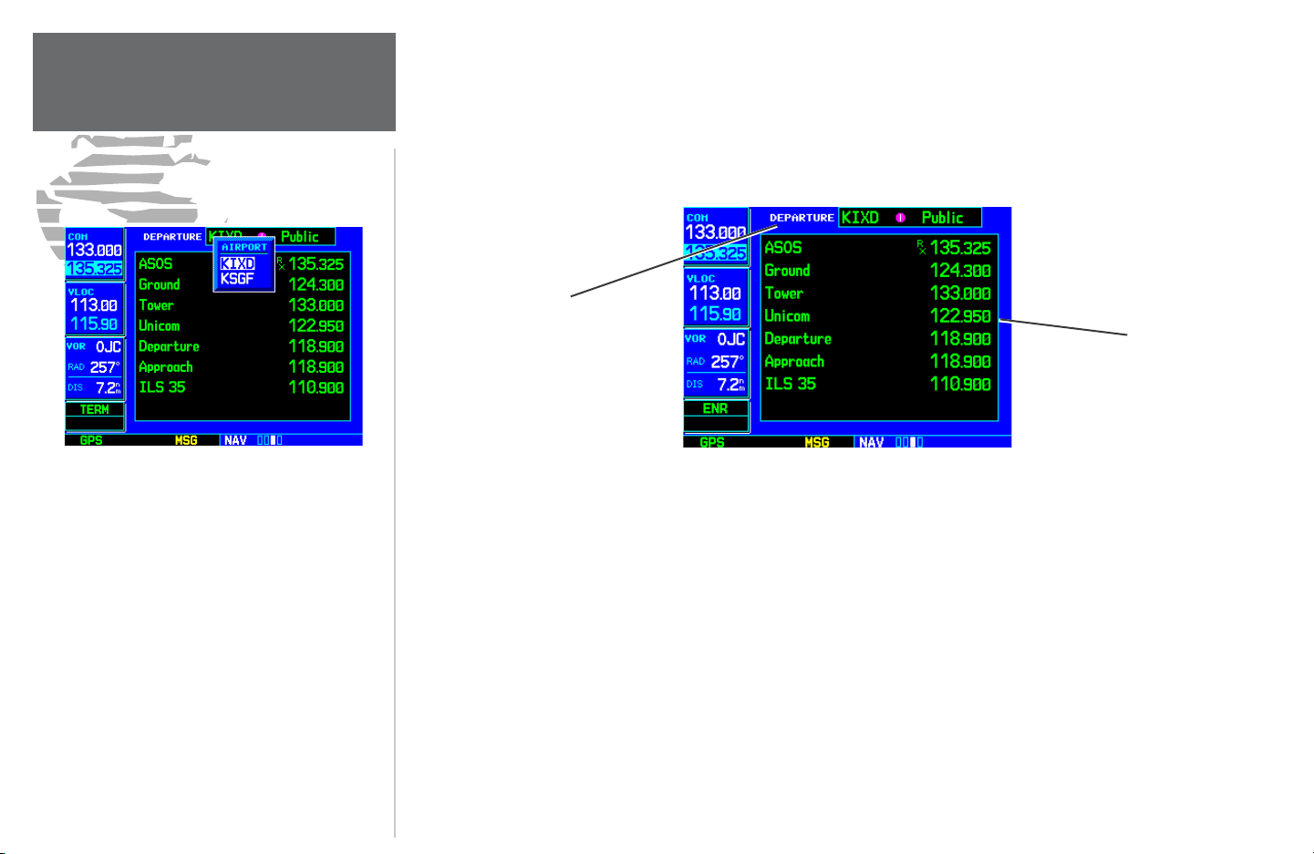
1. Push the small right knob to activate the cursor on the airport identifi er fi eld (in the GPS window).
2. Rotate the small right knob to display the list of airports (departure, arrival and en route) for your fl ight plan
or direct-to. Continue to rotate the small right knob until the desired airport is selected.
3. Press ENT to display the frequency list for the selected airport.
Arrival, Enroute
or Departure Airport
Frequency List
The Navigation/Communications (NAVCOM)
Page provides a complete list of airport fre quen cies
at your departure, en-route and arrival airports.
To place a frequency from this list on standby,
highlight the desired frequency and press ENT.
To display frequencies for a different airport along
your fl ight plan, press the small right knob to
highlight the airport iden ti fi er fi eld. Rotate the
small right knob to display the list of airports
within your fl ight plan. Continue rotating the
small right knob to select the desired airport and
press ENT.
14
NAVCOM PAGE
A frequency listed on the NAVCOM Page can be quickly transferred to the standby fi eld of the COM or
VLOC windows. This time saving process prevents having to “re-key” a fre quency already displayed else where
on the screen.
To select a communication or navigation frequency:
1. Push the small right knob to activate the cursor in the GPS window.
2. Rotate the large right knob to select the desired frequency from the list.
3. Press ENT to transfer the selected frequency to the standby fi eld in the COM or VLOC win dow. COM fre quen -
cies automatically go to the standby fi eld of the COM window and navigation frequencies au to mat i cal ly go to
the standby fi eld of the VLOC window, regardless of the window currently highlighted by the cursor.
4. To activate the selected frequency, press the COM or VLOC fl ip-fl op key.
Page 23

Once the direct-to or fl ight plan is confi rmed, the whole range of instrument procedures is available to
you. Departures (SIDs), arrivals (STARs), non-precision and precision ap proach es are stored within the NavData card and available using the PROC key.
To display the Procedures Page, press PROC.
The steps required to select and activate an approach, departure or arrival are very similar. In this in tro ductory section, we’ll show examples of the steps required to select an approach, but keep in mind the same
process also applies to departures and arrivals.
To select an approach, departure or arrival:
1. Rotate the large right knob to highlight the “Select Approach?” option (or “Select Arrival?”/“Select De-
par ture?”) from the Procedures Page.
2. Press ENT to display a list of available procedures for the arrival (when using approaches or STARs) or de-
par ture (when using SIDs) airport.
3. Rotate the small right knob to select the desired procedure and press ENT.
4. For approaches, a window appears to select the desired initial approach fi x (IAF) or a “vectors” option to select
just the fi nal course segment of the approach. Rotate the small right knob to select the desired option and
press ENT. (The “vectors” option extends the fi nal inbound course beyond the fi nal approach fi x, allowing you
to intercept the fi nal course segment beyond its normal limits.)
5. For departures and arrivals, pop-up windows appear to select the desired transition and runway(s). Rotate the
small right knob to select the desired option and press ENT.
6. With “Load?” highlighted, press ENT to add the procedure to the fl ight plan or direct-to.
TAKEOFF TOUR
IFR Procedures
Press the PROC key to display the procedures
page. Rotate the large right knob to select the
desired option.
The selected procedure for the departure or arrival airport is added to the sequence of waypoints in the
fl ight plan or direct-to (as shown on the Active Route Page). You can later “activate” the selected procedure
from the Procedures Page or the Active Flight Plan Page. See pages 56 and 62 for additional information.
A window appears to select the desired procedure.
Use the small right knob to make your selection.
15
Page 24

TAKEOFF TOUR
Nearest Airports
From page 10 you may recall that one of the main page groups, NRST, provides listings for nearest airports or other facilities. The NRST group includes detailed information on the nine nearest airports, VORs,
NDBs, intersections and user-created waypoints within 200 nautical miles of your current position. In addition, pages are also provided to display the fi ve nearest center (ARTCC/FIR) and Flight Service Station (FSS)
points of communication, plus alert you to any special-use or controlled airspace you may be in or near.
To display the NRST pages:
1. If necessary, press the small right knob to remove the cursor from the page.
2. Rotate the large right knob to select the NRST page group, as indicated by “NRST” appearing in the lower
right corner of the screen (see page 10).
3. Rotate the small right knob to select the desired NRST page.
The Nearest Airport Page (shown at left) is one of eight pages available under the NRST group:
• Nearest Airport Page • Nearest Intersection Page
• Nearest NDB Page • Nearest VOR Page
To display a list of nearby air ports, rotate the
large right knob to select the NRST page group
and (if needed) the small right knob to select the
Nearest Airport Page.
To scroll through the list, press the small right
knob, then rotate the large right knob.
16
• Nearest User Waypoints Page • Nearest ARTCC Page
• Nearest FSS Page • Nearest Airspace Page
You may examine both the communication frequencies and runway information directly from the Nearest Airport Page. As discussed earlier for the NAVCOM Page (see page 14), you may also place any displayed
frequency into the standby COM or VLOC fi eld by highlighting the frequency with the cursor and pressing
ENT.
Page 25

To view additional information for a nearby airport:
1. Press the small right knob to activate the cursor.
2. Rotate the large right knob to select the desired airport from the list.
3. Press ENT to display waypoint (WPT) information pages for the selected airport.
4. To display runway and frequency information, press the small right knob to remove the cursor and rotate the
small right knob to display the desired information page.
The Nearest Airport Page may be used in conjunction with the direct-to key to quickly set a course to a
nearby facility in an in-fl ight emergency. Selecting a nearby airport as a direct-to destination overrides your
fl ight plan or cancels a previously selected direct-to destination (you still have the option of returning to your
fl ight plan by cancelling the direct-to. See page 48.)
To select a nearby airport as a direct-to destination:
From the Nearest Airport Page...
1. Press the small right knob to activate the cursor.
2. Rotate the large right knob to select the desired airport from the list.
3. Press the direct-to key, ENT and ENT (again) to navigate to the nearby airport.
From an Airport Information Page...
1. Press the direct-to key, ENT and ENT (again) to navigate to the nearby airport.
TAKEOFF TOUR
Nearest Airports
Additional information for a nearby airport is
available by highlighting an identifi er on the list
and pressing ENT.
To select a nearby airport as a new destination,
highlight its identifi er, press the direct-to key,
ENT and ENT (again).
17
Page 26

TAKEOFF TOUR
Special-use/Controlled Air space
When an airspace alert occurs, the message (MSG)
annunciator fl ashes at the bottom of the screen.
Press MSG to view the alert message.
To view additional information about the airspace,
select the nearest airspace page. Detailed information is available by highlighting the airspace name
and pressing ENT.
The last page in the NRST group, the Nearest Airspace Page, provides information for up to nine controlled or special-use airspaces near or in your fl ight path. Airspace information appears on this page based
upon the same criteria used for airspace alert messages. Nearby airspace information and airspace alert messages are provided according to the following conditions:
• If your projected course takes you inside an airspace within the next ten minutes, the message
“Airspace ahead -- less than 10 minutes” appears.
• If you are within two nautical miles of an airspace and your current course is such that it will take
you inside that airspace, the message “Airspace near and ahead” appears.
• If you are within two nautical miles of an airspace and your current course is such that it will not
take you inside that airspace, the message “Near airspace less than 2nm” appears.
• If you have entered an airspace, the message “Inside Airspace” appears.
By default, airspace alert messages are turned off. When turned on, the message (MSG) annunciator
located directly above the MSG key fl ashes to alert you to the airspace message (see page 147 for information
on enabling airspace alert messages.).
To view an airspace alert message:
1. Press the MSG key. The message page appears with the alert message.
2. Press MSG again to return to the previous display.
Note that the airspace alerts are based upon three-dimensional data (latitude, longitude and altitude) to
avoid nuisance alerts. The alert boundaries for controlled airspace are also sectorized to provide complete
information on any nearby airspace. Additional information about a nearby airspace — such as controlling
agency, frequency and fl oor/ceiling limits — is available from the nearest airspace page (see page 121 and
illustrations shown at left).
18
Page 27

The GNS 530 lets you create up to 20 fl ight plans, with up to thirty-one waypoints in each fl ight plan.
Flight plans are created, edited and activated using the FPL key. The FPL page group includes two pages: the
Active Flight Plan Page and the Flight Plan Catalog. The Active Flight Plan Page provides in formation and
editing features for the fl ight plan currently in use (re ferred to as “fl ight plan 00”). The Flight Plan Catalog
serves as the main page for creating new fl ight plans, as well as editing or activating previously created fl ight
plans.
Since using fl ight plans is arguably one of the more complex features of the GNS 530, we’ll only discuss
it briefl y here — focusing on creating a new fl ight plan and activating it to use for navigation. After reading
through this brief introduction, answers to additional questions you may have about fl ight plans can be found
in the reference section, starting on page 49.
To create a new fl ight plan:
1. Press the FPL key and rotate the small right knob to select the Flight Plan Catalog.
2. Press the MENU key to display the Flight Plan Catalog Options.
3. Rotate the large right knob to select “Create New Flight Plan?” and press ENT.
4. The cursor appears on the fi rst waypoint identifi er fi eld (located directly below “WAYPOINT”). Use the large
and small right knobs to enter the identifi er of the fi rst waypoint in the fl ight plan (the small knob is used to
select the desired letter or number and the large knob is used to move to the next character space.).
5. Press ENT once the identifi er has been selected. The cursor moves to the next blank waypoint identifi er fi eld.
6. Repeat steps 4 and 5, above, until all waypoints for the fl ight plan have been entered.
TAKEOFF TOUR
Flight Plans
Active Flight Plan Page with fl ight plan currently
in use.
To create a new fl ight plan, select “Create New
Flight Plan?” from the Flight Plan Catalog Options.
19
Page 28

TAKEOFF TOUR
Additional Reading
Once the fl ight plan is created, it may be activated from an options window. Activating the fl ight plan
places it into “fl ight plan 00” (a copy of it still resides in the original catalog location) and replaces any fl ight
plan which currently exists in “fl ight plan 00.”
To activate the new fl ight plan:
1. Press the MENU key to display the Flight Plan Catalog Options.
2. Rotate the small right knob to select “Activate Flight Plan?” and press ENT.
This Takeoff Tour is intended to provide a brief introduction of the GNS 530’s major fea tures. The reference section of this manual describes these features, and others, in additional detail. Use the reference section,
as needed, to learn or review the details regarding a par ticular feature. The Index (see page 184) may be used
to quickly locate the information you want within the reference section.
Now that you’re familiar with the basics, some suggested additional reading includes:
Enter the identifi er for each airport and/or navaid
into the fl ight plan in the same sequence you wish
to fl y.
Select “Activate Flight Plan?” from the page menu
to begin using the new fl ight plan.
20
• Flight plan features - see page 49
• Waypoint information pages (database information) - see page 88
• IFR procedures - see page 61
• Unit settings (confi guring the unit to your preferences) - see page 144
If you’re unable to locate the information you need, we’re here to help! Garmin’s Customer Service staff is
available during normal business hours (U.S. Central time zone) at the phone and fax numbers listed on page
iv. You can also reach us by mail (see page iv) or at our web site address: www.garmin.com.
Page 29

Section 1: Communicating with the GNS 530
The GNS 530 features a digitally-tuned VHF COM radio that provides a seamless transition from communication to navigation, bringing the two most important functions in fl ying together in one panel-mounted
unit. The GNS 530’s COM radio operates in the aviation voice band, from 118.000 to 136.975 MHz, in 25
kHz steps (default). For European operations, a COM radio confi guration to allow for 8.33 kHz steps is also
provided (see page 154).
Volume
COM radio volume is adjusted using the COM power/volume knob. Rotate the COM power/volume
knob clockwise to increase volume, or counterclockwise to decrease volume.
Squelch
The COM radio features an automatic squelch, providing maximum sensitivity to weaker signals while
rejecting many localized noise sources. You may wish to override this automatic squelch function when listening to a distant station or when setting the desired volume level. The COM power/volume knob allows you
to disable the automatic squelch and keep the COM audio open continuously.
To override the automatic squelch, press the COM power/volume knob momentarily. Press
COM power/volume knob again to return to automatic squelch operation.
Press the COM power/volume knob mo men tari ly to override the automatic squelch. Note the
“RX” receive indication when receiving a station.
1 - COM
Radio Volume / Auto Squelch
“TX” appears at the upper right corner of the
COM window while transmitting.
21
Page 30

1 - COM
Tuning Active & Standby Freqs
COM Window and Tuning
Communication frequencies are selected with the tuning cursor in the standby COM frequency fi eld, and
using the small and large left knobs to dial in the desired frequency. The standby frequency always appears
below the active frequency. The active frequency is the frequency currently in use for transmit and receive
operations.
A frequency may also be quickly selected from the database by simply highlighting the desired frequency
on any of the main pages and pressing ENT. This process is referred to as “auto-tuning”. Once a frequency is
selected in the standby fi eld, it may be transferred to the active frequency by pressing the COM fl ip-fl op key.
While receiving a station, an “RX” indication appears in the upper right corner of the COM
window — to the immediate right of “COM”. A “TX” indication appears at this location while you are transmitting.
Tuning cursor in the COM window. Use the small
and large left knobs to dial in the desired standby
frequency.
Once the standby frequency is selected, use the
COM fl ip-fl op key to make the frequency active
for transmit and receive operations.
22
)
NOTE: The tuning cursor normally appears in the COM window, unless placed in the VLOC window
by pressing the small left knob. When the tuning cursor is in the VLOC window, it au to mat i cal ly
returns to the COM window after 30 seconds of inactivity. The active frequency in either window
cannot be accessed directly — only the standby frequency is highlighted by the tuning cursor.
Page 31

To select a COM frequency:
1. If the tuning cursor is not currently in the COM window, press the small left knob momentarily.
2. Rotate the large left knob to select the desired megahertz (MHz) value. For example, the “118” portion of
the frequency “118.300”.
3. Rotate the small left knob to select the desired kilohertz (kHz) value. For example, the “.300” portion of the
frequency “118.300”.
To make the standby frequency the active frequency, press the COM fl ip-fl op key.
The tuning cursor remains in the COM window. If you wish to select a VOR/localizer/ILS fre quency, press
the small left knob momentarily to place the cursor in the VLOC window. Additional in structions for VOR/
localizer/ILS operations are available in Sections 5 and 8 (beginning on pages 61 and 125).
Auto-Tuning
1 - COM
Auto-Tuning / Nearest Apt Page
The GNS 530’s auto-tune feature allows you to quickly select any database frequency in the GPS window as your standby frequency. Any COM frequency displayed in the GPS window can be trans ferred to the
standby COM frequency fi eld, with a minimum of keystrokes required. The fol lowing are some examples of
selecting COM frequencies from some of the main GPS pages.
To select a COM frequency for a nearby airport:
1. Select the Nearest Airport Page from the NRST page group. (See page 113, or press and hold CLR, then rotate
the large right knob until the nearest pages appear. Finally, if necessary, rotate the small right knob to
display the Nearest Airport Page.)
2. Press the small right knob momentarily to place the cursor on the airport identifi er fi eld of the fi rst airport in
the list. If you wish to select another airport, rotate the large right knob to highlight the desired airport.
3. The Nearest Airport Page displays the common traffi c advisory frequency (CTAF) for each listed airport. To
select this frequency, rotate the large right knob to highlight the desired airport’s CTAF frequency and press
ENT to place the frequency in the standby fi eld of the COM window.
Cursor in VLOC window allows for VOR and ILS
operations. See Section 8, starting on page 125.
Nearest Airport Page with common traffi c advisory
frequency (CTAF) for the closest airport highlighted.
23
Page 32

1 - COM
Auto-Tuning FSS & Center Freqs
From the Nearest Airport Page, select the desired
airport to show a more detailed listing of frequencies for that airport.
To display the entire list of frequencies for a nearby airport and select from that list:
1. Start with the desired airport highlighted on the Nearest Airport Page (as described on the previous page), then
press ENT.
2. Press the small right knob momentarily to remove the cursor and rotate the small right knob to display
the frequency list.
3. Press the small right knob momentarily to reactivate the cursor and rotate the large right knob to high-
light the desired frequency.
4. Press ENT to place the highlighted frequency in the standby COM window fi eld.
To select a COM frequency for a nearby fl ight service station (FSS) or center (ARTCC):
1. Select the Nearest Center or Flight Service Page from the NRST page group. (See page 113, or rotate the large
right knob until the NRST pages appear. Then, if necessary, rotate the small right knob to display the
desired NRST page.)
2. Press the small right knob momentarily to place the cursor on the page.
3. Rotate the large right knob to highlight the FSS/ARTCC frequency and press ENT to place the frequency in
the standby fi eld of the COM window.
Use the nearest ARTCC Page to quickly retrieve
the frequency(s) for the nearest center (ARTCC)
facility.
24
Page 33

To select a COM frequency for any airport in your fl ight plan:
1. Select the NAVCOM Page from the NAV page group. (See page 27, or press and hold CLR, then rotate the
small right knob until the NAVCOM Page appears.)
2. Press the small right knob to place the cursor on the airport identifi er fi eld. To the left of this fi eld appears
Departure, Enroute or Arrival — depending on the placement of the displayed airport within your fl ight plan.
3. Rotate the small right knob to display a window listing the airports in your fl ight plan. Continue rotating the
small right knob to select the desired airport.
4. Press ENT to return to the NAVCOM Page with the frequencies for the selected airport.
5. Rotate the large right knob to highlight the desired frequency.
6. Press ENT to place the highlighted frequency in the standby COM window fi eld.
To select a COM frequency for any airport in the database:
1. Select the Airport Frequencies Page from the WPT page group. (See page 88, or rotate the large right knob
to select the WPT page group. Then rotate the small right knob until the Airport Frequencies Page appears.)
2. Press the small right knob to place the cursor on the airport identifi er fi eld.
3. Use the small and large right knobs to enter the identifi er of the desired airport. Press ENT when fi nished.
4. Rotate the large right knob to highlight the desired frequency.
5. Press ENT to place the highlighted frequency in the standby COM window fi eld.
1 - COM
Auto-Tuning from Flight Plan
The NAVCOM Page provides a frequency list for
all the airports (departure, en route and arrival)
along your active fl ight plan.
Use the Airport Frequencies Page to retrieve a
frequency list for ANY airport in the Jeppesen
NavData database.
25
Page 34

1 - COM
Emergency Channel / Stuck Mic
Press and hold the COM fl ip-fl op key for two
seconds to activate the 121.500 MHz emergency
frequency.
Emergency Channel
The GNS 530’s emergency channel select provides a quick method of selecting 121.500 MHz as the active
frequency in the event of an in-fl ight emergency. The emergency channel select is available whenever the unit
is on, regardless of GPS or cursor status, or loss of the display.
To quickly tune and activate 121.500, press and hold the COM fl ip-fl op key for ap prox i-
mately two sec onds.
Stuck Microphone
As mentioned earlier, whenever the GNS 530 is transmitting, a “TX” indication appears in the COM
window. If the microphone is stuck or ac cidentally left in the keyed position, or continues to transmit after
the key is released, the COM transmitter automatically times out (or ceases to trans mit) after 35 seconds of
continuous broadcasting. You will also receive a “COM push-to-talk key stuck” message as long as the stuck
condition exists.
A “COM push-to-talk key stuck” message appears
to warn you of a stuck microphone. Transmitting is
disabled after 35 seconds of continuous broad cast ing.
26
Page 35

Section 2: NAV Pages
Main Page Groups
The GNS 530’s main pages are divided into groups: NAV, WPT, AUX and NRST. While viewing any of these
pages, selection of another page is a simple selection process using the small and large right knobs.
2 - NAV PAGES
Page Groups / NAV Page Group
NAV
4 available pages*
(see below)
WPT
10 available pages
(see list pg. 88)
AUX
3 available pages
(see list pg. 131)
NRST
8 available pages
(see list pg. 113)
To select the desired page group, rotate the large right knob until a page from the desired
group is displayed.
To select the desired page within the group, rotate the small right knob until the desired
page is displayed.
NAV Page Group
Default NAV
Map
NAVCOM
Satellite Status
The NAV page group includes four pages*. While viewing any NAV page, rotate the small right knob to
select a different NAV page. You may fi nd this selection process convenient to cycle between the Default NAV
and Map Pages — two of the most frequently used pages. Other pages are provided to list fre quencies for
your fl ight plan, show your current position and display current satellite reception.
The bottom right corner of the screen indicates the
page group that is currently being displayed (e.g.
NAV or NRST), the number of screens available
within that group (indicated by square icons) and
the placement of the current screen within that
group (indicated by a highlighted square icon). To
select a different page within the group, rotate the
small right knob.
This part of the screen is also used to display the
GNS 530’s turn advisories (e.g., “TURN TO 355°”)
and waypoint alerts (e.g., “NEXT DTK 355°”)
during fl ight plan and approach operations. See
Section 5 for more information.
* Five NAV pages are available when the GNS 530
installation includes connection to traffi c and/or
weather information sources. See 400/500 Series Display
Interfaces Pilot's Guide Addendum.
27
Page 36

2 - NAV PAGES
Default NAV Page
The following symbols are used — on the Default
NAV Page directly above the graphic CDI — to
depict the “active leg” of a fl ight plan or direct-to.
Direct-To a Waypoint
Course to a Waypoint, or Desired
Course between Two Waypoints
Left Procedure Turn
Right Procedure Turn
Vectors-To-Final
DME Arc to the left
DME Arc to the right
Left-Hand Holding Pattern
Right-Hand Holding Pattern
28
Default NAV Page
User-selectable Data Fields
Active Leg of Flight Plan,
or Direct-to Destination
First Page in NAV Group
(all four corners)
Course Deviation
Indicator (CDI)
The fi rst NAV page is the Default NAV Page. This page may be quickly selected from ANY page by using
the CLR key.
To select the NAV group and display the Default NAV Page, press and hold CLR.
The Default NAV Page provides a “look ahead” map display with your present position at the bottom center of the page. The top of the page displays desired track (DTK), ground track (TRK) and distance to des tination waypoint (DIS). The bottom of the page indicates ground speed (GS), active to/from waypoints (only
active to, for a direct-to destination) and estimated time en route. A graphic course de viation in dicator (CDI)
also appears at the bottom of the page. Unlike the angular limits used on a me chanical CDI cou pled to a VOR
or ILS receiver, full scale limits for this CDI are defi ned by a GPS-derived distance (0.3, 1.0 or 5.0 nm). By
default, the CDI scale automatically adjusts to the desired limits based upon the current phase of fl ight: en
route, terminal area or approach. You may also manually select the desired scale setting as outlined on page
148.
The graphic CDI shows your position at the center of the indicator, relative to the desired course (the
moving course deviation needle). As with a traditional mechanical CDI, when you’re off course simply steer
toward the needle. The TO/FROM arrow in the center of the scale indicates whether you are heading to the
waypoint (an up arrow) or if you have passed the waypoint (a down arrow).
Page 37

)
NOTE: The GNS 530 always navigates TO a waypoint unless the OBS switch is set (preventing automatic waypoint sequencing), or you have passed the last waypoint in your fl ight plan.
Directly above the CDI appears the active leg of your fl ight plan, or the direct-to destination when using the
direct-to key. This automatically sequences to the next leg of your fl ight plan as you reach each interim waypoint. If no fl ight plan or direct-to destination has been selected, this line remains blank.
The scale of the “look ahead” map display appears in the bottom left corner. Nine scale settings, ranging
from 5.0 nm to 200 nm are available. Use the RNG key to select the desired scale.
To adjust the map scale:
1. Press the up arrow on the RNG key to zoom out to a larger area. OR,
2. Press the down arrow on the RNG key to zoom in to a smaller area.
2 - NAV PAGES
Default NAV Page
Selecting Desired On-Screen Data
At the corners of the Default NAV Page are four user-defi nable fi elds which display the data you need
as your fl ight progresses. By default, these fi elds display desired track (DTK), dis tance to destination (DIS),
ground speed (GS) and estimated time en route (ETE). How ever, each of these fi elds can be custom-tailored
to your preferences by selecting a different data item. Available data items include:
• Bearing to destination (BRG) • Course to steer (CTS)
• Distance to destination (DIS) • Desired track (DTK)
• En-route safe altitude (ESA) • Estimated time of arrival (ETA)
• Estimated time en route (ETE) • Total Fuel Flow (FLOW)
• Ground speed (GS) • Minimum safe altitude (MSA)
• Track angle error (TKE) • Ground track (TRK)
• Vertical speed required (VSR) • Cross track error (XTK)
Nine map scale settings are available on the Default NAV Page — from 5.0 to 200 nautical miles.
To adjust the map scale, use the RNG key.
To change the data type displayed at any of the
four corners on the page, press MENU and select
the “Change Fields?” option.
29
Page 38

2 - NAV PAGES
Default NAV Page
If no fl ight plan or direct-to destination has been selected only speed, track, altitude, fuel fl ow and minimum safe altitude data may be displayed. All other data types appear as blank lines — on the Default NAV
Page — until a destination is selected.
To select a different data item for any data fi eld:
1. Starting with the Default NAV Page, press the MENU key to display an options menu.
2. Rotate the large right knob to highlight “Change Fields?” and press ENT to select this option.
3. Use the large right knob to highlight the data fi eld you wish to change.
4. Rotate the small right knob to display the list of available data items. Continue rotating the small right
knob to select the desired data item from the list.
5. Press ENT to select the desired data item and return to the Default NAV Page.
6. Press the small right knob momentarily to remove the cursor from the page.
Once “Change Fields?” is selected, use the large
right knob to select the fi eld you wish to change
and the small right knob to select the new data
type.
The “Restore Defaults?” option returns all data
fi elds to their original factory settings.
30
Restoring Factory Settings
You can also quickly return all data fi eld settings to their original factory settings.
To restore all four selectable data fi elds to factory default settings:
1. Starting with the Default NAV Page, press the MENU key to display an options menu.
2. Rotate the large right knob to highlight the “Restore Defaults?” option and press ENT.
Dual Unit Considerations
A “Crossfi ll?” option is provided from the Default NAV Page. This option allows you to transfer a directto destination, the active fl ight plan, any stored fl ight plan or user waypoints to a second 500-series Garmin
unit.
Some crossfi ll operations can be done automatically. If both 500-series units are set to “auto”, a change in
the direct-to destination or active fl ight plan on one unit can also be seen on the other. See page 53 for additional details on using the “Crossfi ll?” option.
Page 39

Auto Zoom
An autozoom feature is available for the Default NAV Page, which automatically adjusts from an en-route
scale of 200 nautical miles through each lower scale, stopping at 5.0 nautical miles as you ap proach your
destination waypoint. By default, the autozoom feature is disabled.
To enable (disable) the autozoom feature:
1. Starting with the Default NAV Page, press the MENU key to display an options menu.
2. Rotate the large right knob to highlight “Enable Auto Zoom?” (or “Disable Auto Zoom?”) and press ENT to
select this option.
Map Page
2 - NAV PAGES
Default NAV Page
Map Display
Map Scale
Present Position
Desired Track
Second Page in NAV Group
The second NAV page is the Map Page, which displays your present position using an airplane symbol,
along with nearby airports, navaids, user-defi ned waypoints, airspace boundaries, lakes, rivers, high ways and
cities.
)
NOTE: If the GNS 530 is unable to determine a GPS position, the present position (airplane)
symbol does not appear on the Map Page.
Autozoom automatically adjusts the map scale as
you approach your destination waypoint.
The Map Page is the second of four Nav pages (fi ve
if equipped with weather and/or traffi c systems).
The map scale is depicted in the lower left corner
and adjusted with the RNG key.
31
Page 40

2 - NAV PAGES
Map Page
Examples of several symbols used to depict airports
and navaids on the Map Page. Note the airports,
Locator Outer Marker, VORTAC and Intersections.
The map scale appears in the lower left corner. Use
the RNG key to select the desired map scale.
32
Different symbols are used to distinguish between waypoint types. The identifi ers for any on-screen
waypoints can also be displayed. (By default the identifi ers are enabled.) Special-use and controlled airspace
boundaries appear on the map, showing the individual sectors in the case of Class B or Class C airspace. The
following symbols are used to depict the various airports and navaids on the Map Page:
Airport with hard surface runway(s); Primary runway shown
Airport with soft surface runway(s) only
Private Airfi eld Intersection
VOR VORTAC
VOR/DME TACAN
DME NDB
Localizer Locator Outer Marker
The map display can be set to 23 different scale settings from 500 feet to 2000 nautical miles (statute and
metric units are also available). The scale is indicated in the lower left-hand corner of the map display, and
represents the top-to-bottom distance covered by the map display.
To select a map scale:
1. Press the up arrow side of the RNG key to zoom out to a larger map area.
2. Press the down arrow side of the RNG key to zoom in to a smaller map area and more detail.
An autozoom feature is available which automatically adjusts from an en-route scale of 2000 nm through
each lower scale, stopping at a scale of 1.0 nm as you approach your destination waypoint. The autozoom
feature is turned on/off from the map setup page described on page 35.
The Map Page also displays a background map showing lakes, rivers, coastlines, highways, railways and
towns. When a map scale is selected below the lower limit at which the map detail was originally created, an
“overzoom” indication appears on the map display, below the scale reading. “Overzoom” indicates that the
detail at this scale may not accurately represent actual conditions (and extra caution should be observed when
these scales are used for navigation).
Page 41

The “Setup Map?” option (described on page 35) allows you to defi ne the maximum scale at which
each map feature appears. This provides you with complete control to minimize screen clutter. You can also
quickly remove items from the map using the CLR key.
To quickly declutter the map display, press the CLR key momentarily (as often as needed)
to select the desired amount of map detail.
Five user-selectable data fi elds can be added to the right-hand side of the Map Page. By default, the displayed data is destination waypoint name (WPT), desired track (DTK), ground track (TRK), distance to des tination waypoint (DIS) and ground speed (GS). Adding these data fi elds or changing the data types is outlined
on pages 37-38.
Map Panning
Another Map Page function is panning, which allows you to move the map beyond its current limits
without adjusting the map scale. When you select the panning function — by pressing the small right knob
— a target pointer fl ashes on the map display. A window also appears at the top of the map display showing
the latitude/longitude position of the pointer, plus the bearing and distance to the pointer from your present
position.
To select the panning function and pan the map display:
1. Press the small right knob to activate the panning target pointer.
2. Rotate the small right knob to move up (rotate clockwise) or down (counterclockwise).
3. Rotate the large right knob to move right (rotate clockwise) or left (counterclockwise).
4. To cancel the panning function and return to your present position, press the small right knob.
2 - NAV PAGES
Map Page
To quickly declutter the map, press CLR. Continue
pressing CLR to select the desired declutter level.
Note the scale is followed “-1”, “-2” or “-3”.
When the target pointer is placed on an object, the name of that object is highlighted (even if the name
wasn’t originally displayed on the map). This feature applies to airports, navaids, user-created waypoints,
roads, lakes, rivers — just about everything displayed on the map except route lines.
When an airport, navaid, or user waypoint is selected on the map display, you can review in formation
about the waypoint or designate the waypoint as your direct-to destination.
Panning the map lets you look beyond the boundaries of the current map area without changing the
scale. Start by pressing the small right knob.
33
Page 42

2 - NAV PAGES
Map Page
Use the panning function and direct-to key to select
a destination waypoint directly from the map.
“+MAP” is created as a waypoint if nothing exists
at the pointer’s location.
Use the panning function and ENT key to retrieve
airspace information from the map.
34
To review information for an on-screen airport, navaid or user waypoint:
1. Use the panning function (as described on the previous page) to place the target pointer on a waypoint.
2. Press ENT to display the waypoint information page(s) for the selected waypoint.
3. Press CLR to exit the information page(s).
Map Direct-To
To designate an on-screen airport, navaid or user waypoint as your direct-to destination:
1. Use the panning function (see previous page) to place the target pointer on a waypoint.
2. Press the direct-to key. The Select Direct-to Waypoint Page appears, with the selected waypoint already listed.
3. Press ENT twice to confi rm the selection and begin navigating to the waypoint.
The direct-to function can be used anywhere on the map. If nothing currently exists at the crosshair
position, a new waypoint (called “+MAP”; shown at left) is created at the target pointer location before the
direct-to is initiated.
Airspace Information on the Map
When a special-use or controlled airspace boundary appears on the map display, you can quickly retrieve
information — such as fl oor/ceiling limits and controlling agency — directly from the map.
To view airspace information for an on-screen special-use or controlled airspace:
1. Use the panning function (see previous page) to place the target pointer on an open area within the boundaries of an airspace. If the area is congested and it is diffi cult to select an open area, you may need to zoom in or
press CLR to make the selection easier.
2. Press ENT to display an options menu.
3. “Review Airspace?” should already be highlighted. If not, select it with the small right knob. Press ENT to
display the airspace information page for the selected airspace.
4. To display the com frequency(s) for the controlling agency, rotate the large right knob to highlight “Fre quen -
cies?” and press ENT. Press CLR to return to the airspace information page.
5. Press CLR to exit the airspace information page.
Page 43

Many of the GNS 530’s functions are menu driven. Each of the main pages has an options menu, allowing
you to custom tailor the corresponding page to your preferences and/or select special features which specifi cally relate to that page. A Map Page Options menu provides additional settings to cus tomize the Map Page
and additional features related specifi cally to the Map Page.
To display the Map Page Options menu, press MENU (with the Map Page displayed).
The following options are available: “Setup Map?”, “Measure Dist?”, “Data Fields Off?”, “Clear Storm
Data?”*, “Change Fields?” and “Restore Defaults?”.
Map Setup
“Setup Map?” allows you to confi gure the map display to your preferences, including map ori entation,
land data enable/disable, Jeppesen data enable/disable, automatic zoom, airspace boundaries, and text size.
The following table lists the group names and available settings:
With the Map Page displayed, press MENU to dis-
Map Orientation, AutoZoom, Land Data, Aviation Data, Wind Vector
Weather* Lightning Mode, Lightning Symbol
play the Map Page Options menu. Use the large
right knob to select the desired option.
Traffi c* Traffi c Mode, Traffi c Symbol, Traffi c Label
Line/Road
Waypoint
Active Flight Plan/Direct-To, Lat/Lon Grid, Freeways, National Highways, Local
Highways, Local Roads, Railroads
Active Flight Plan Waypoints, Large/Medium/Small Airports, Intersections, NDBs,
VORs, User Waypoints, Waypoint Text
Airspace Class B, Class C, Tower Zone, Restricted, MOA, Other
City/Other Large/Medium/Small Cities and Text, State/Province Boundaries, Rivers/Lakes
2 - NAV PAGES
Map Page Options
* Weather and Traffi c settings are only available when
the GNS 530 installation includes connection to traffi c
and/or weather information sources. See 400/500 Series
Display Interfaces Pilot's Guide Addendum.
35
Page 44

2 - NAV PAGES
Map Page Options
To select a map setup group, rotate the small
right knob. Rotate the large right knob to high-
light the desired setting within the group.
Large, Medium and Small classifi cations are used
on the GNS 530 for airports and cities. Large
airports are those with a runway longer than 8100
feet. Medium airports include those with a runway
longer than 5000 feet or with a control tower.
Large cities are those with approximate populations greater than 200,000 and Medium cities are
greater than 50,000.
* Wind Vector information can only be displayed if
your GNS 530 installation includes connections to
an air data system.
36
To change a map setup feature:
1. Press MENU (with the Map Page displayed).
2. Rotate the large right knob to highlight “Setup Map?” and press ENT.
3. To change map orientation: Rotate the small right knob to select “Map” and press ENT. Rotate the large
right knob to highlight the “Ori en ta tion” fi eld, then rotate the small right knob to select the desired op-
tion . Select “North up” to fi x the top of the map display to a north heading. Select “Track up” to adjust the
top of the map display to your current ground track heading. Select “DTK up” to fi x the top of the map display
to your desired course. Press ENT to accept the selected option.
4. To enable/disable automatic zoom: Rotate the small right knob to select “Map” and press ENT. Rotate the
large right knob to highlight the “Auto Zoom” fi eld and rotate the small right knob to select “On” or
“Off”. Press ENT to accept the selected option. The automatic zoom feature au to mat i cal ly adjusts the map
scale from 2000 nm through each lower scale, stopping at 1.0 nm as you approach your destination waypoint.
5. To enable/disable all background land data or Jeppesen aviation data: Rotate the small right knob to select
“Map” and press ENT. Use the large right knob to highlight the appropriate fi eld and rotate the small
right knob to select “On” or “Off”. Press ENT to accept the selected option.
6. To enable/disable the on-screen wind vector*: Rotate the small right knob to select “Map” and press ENT.
Use the large right knob to highlight the “Wind Vector” fi eld and rotate the small right knob to select
“On” or “Off”. Press ENT to accept the selected option.
7. For airports, NAVAIDs, active fl ight plan waypoints, user-created waypoints, state/provincial boundaries, rivers/
lakes and cities: Rotate the small right knob to select the appropriate “Group” name (per the chart on the
previous page) and press ENT. Use the large right knob to highlight the “RNG” fi eld for the desired feature
and rotate the small right knob to select the maximum scale at which the feature should appear on screen.
Or select “Off” to never display the selected feature. Press ENT to accept the selected option. Next, rotate the
large right knob to highlight the “TEXT” fi eld for the desired feature and rotate the small right knob to
select the desired text size, or select “Off” to disable text descriptions. Press ENT to accept the selected option.
8. For airspace boundaries, highways, roads, railroad lines, active fl ight plan course lines, and lat/long grid lines:
Rotate the small right knob to select the appropriate “Group” name (per the chart on the previous page)
and press ENT. Use the large right knob to highlight the “RNG” fi eld for the desired feature and rotate the
small right knob to select the maximum scale at which the feature should appear on screen. Or select “Off”
to never display the selected feature. Press ENT to accept the selected option.
Page 45

Distance Measurements
The “Measure Dist?” option provides a quick, easy method for determining the bearing and distance be-
tween any two points on the map display.
To measure bearing and distance between two points:
1. Press MENU (with the Map Page displayed).
2. Rotate the large right knob to highlight “Measure Dist?” and press ENT. An on-screen reference pointer
appears on the map display at your present position.
3. Use the small and large right knobs to place the reference pointer at the location you wish to measure
FROM and press ENT.
4. Again, use the small and large right knobs to place the reference pointer at the location you wish to measure TO. The bearing and distance from the fi rst reference location appear at the top of the map display.
5. To exit the “Measure Dist?” option, press the small right knob.
Adding Data Fields to the Map
The “Data Fields On?” option provides a map display (shown at right) with fi ve user-selectable data fi elds
along the right-hand side of the screen. Select this option when you wish to display additional on-screen data
— such as destination waypoint name (WPT), desired track (DTK), ground track (TRK), distance to destination (DIS) and ground speed (GS). If this option has been selected and the data fi elds are being displayed,
“Data Fields Off?” appears as an option instead.
To turn the data fi elds on (or off), rotate the large right knob to highlight “Data Fields
On?” (or “Data Fields Off?”) and press ENT.
2 - NAV PAGES
Map Page Options
Once “Measure Dist?” is selected, place the
on-screen pointer on the point you wish to measure
FROM and press ENT.
Clearing On-Screen Weather Data
“Clear Storm Data?” removes storm history information from the map. New storm data appear as detected
and relayed by a connected weather data source. Weather data and the “Clear Storm Data?” option are only
available when the GNS 530 installation includes connection to weather information sources. See 400/500
Series Display Interfaces Pilot's Guide Addendum.
“Data Fields On?” adds fi ve user-selectable data
fi elds to the right-hand side of the page. Select
“Change Fields?” to change any of these fi elds to a
different data type.
37
Page 46

2 - NAV PAGES
Map Page Options
Selecting Desired On-Screen Data
“Change Fields?” allows you to choose the data displayed on the fi ve user-selectable data fi elds along the
right-hand side of the map page (see previous page). There are sixteen available data types, in cluding bearing
to destination, distance to destination, estimated time of arrival, ground speed, minimum safe altitude and
track. See page 172 for descriptions of these (and other) navigation terms.
To change a data fi eld:
1. Press MENU (with the Map Page displayed).
2. Rotate the large right knob to highlight “Change Fields?” and press ENT.
3. Rotate the large right knob to highlight the data fi eld you wish to change.
4. Rotate the small right knob to select the type of data you want to appear on this fi eld and press ENT.
5. Press the small right knob to remove the cursor.
Once “Change Fields?” is selected, rotate the large
right knob to highlight the data fi eld you wish to
change, then rotate the small right knob to select
the type of data to display in that fi eld.
“Restore Defaults?” resets all fi ve user-selectable
data fi elds to their original factory settings.
38
)
NOTE: The on-screen traffi c information (TRFC) occupies two data fi elds, leaving room to display
only three additional data types. Traffi c information is only available when the GNS 530 installation
includes connection to traffi c information sources. See 400/500 Series Display Interfaces Pilot's
Guide Addendum.
Restoring Factory Settings
“Restore Defaults?” resets all fi ve user-selectable data fi elds to their original factory default settings.
To restore the factory default settings, rotate the large right knob to highlight “Restore
Defaults?” (see bottom left) and press ENT.
Page 47

NAVCOM Page
Departure, Enroute
or Arrival Airport
Frequency Type
Assigned Frequency
and Usage Informa-
tion (when applicable)
Third Page in NAV Group*
The third NAV page is the NAVCOM (navigation communications) Page. The NAVCOM Page provides a
list of the airport communication and navigation frequencies at your departure, en-route and arrival airports. The NAVCOM Page makes selection of the frequencies you’ll need along your fl ight plan quick and
convenient. If you do not have an active fl ight plan with a departure airport, the NAVCOM Page displays the
frequencies for the airport nearest your departure position.
2 - NAV PAGES
NAVCOM Page
*If your installation includes connection to traffi c
and/or weather systems, the Traffi c/Weather Page
appears as one of fi ve available NAV pages.
)
NOTE: The NAVCOM Page is the fourth page in the NAV group when the GNS 530 installation
includes connection to traffi c and/or weather information sources. See 400/500 Series Display
Interfaces Pilot's Guide Addendum.
To select a frequency list for a departure, en-route or arrival airport:
1. Press the small right knob to activate the cursor.
2. Rotate the large right knob to place the cursor on the airport identifi er fi eld (top line on the NAVCOM Page).
3. Rotate the small right knob to select the desired airport and press ENT.
The NAVCOM Page lists available frequencies for
your departure, en-route and arrival airports.
39
Page 48

2 - NAV PAGES
NAVCOM Page
To scroll through the list of frequencies:
1. Activate the cursor, if not already active, by pressing the small right knob.
2. Rotate the large right knob to move the cursor through the list of frequencies. If there are more frequencies
in the list than can be displayed on the screen, a scroll bar along the right-hand side of the screen indicates the
part of the list that is currently being displayed.
3. To place a frequency in the standby fi eld of the COM or VLOC window, highlight the desired frequency (using
the large right knob) and press ENT.
Some listed frequencies may include designations for limited usage, as follows:
“TX” - transmit only “RX” - receive only
“PT” - part time frequency
If a listed frequency has sector or altitude restrictions, the frequency is preceded by an “Info?” designation.
The scroll bar along the right-hand side of the page
indicates the length of the NAVCOM frequency
list and what portion of the list is currently being
displayed.
Highlight “Info?” adjacent to the desired frequency
and press ENT to display usage restrictions for the
corresponding frequency.
40
To view usage restrictions for a frequency:
1. Rotate the large right knob to place the cursor on the “Info?” designation directly in front of the desired
fre quen cy.
2. Press ENT to display the restriction information.
3. To return to the NAVCOM Page, press ENT.
Page 49

Satellite Status Page
The Satellite Status Page (the last NAV page) provides a visual reference of GPS receiver functions, including current satellite coverage, GPS receiver status, position accuracy, and displays your present position (by
default, in latitude and lon gitude) and altitude. The Satellite Status Page also displays the current time at
the bottom center of the page. The altitude fi eld (ALT) is user-selectable to confi gure the page to your own
pref er ences and current nav igation needs.
2 - NAV PAGES
Satellite Status Page
Location of Satel-
lites in view
“INTEG” Annunciator
(fl agged when position
not valid)
To change the user-selectable data fi eld:
1. Press MENU to display the Satellite Status Page Options menu.
2. Rotate the large right knob to highlight “Change Fields?” and press ENT.
3. Rotate the small right knob to display the list of available data items. Continue rotating the small right
knob to select the desired data item from the list.
5. Press ENT to select the desired data item and return to the position page.
6. Press the small right knob momentarily to remove the cursor from the page.
Receiver Status
Current Time
Fourth Page in NAV Group
(fi fth with traffi c/weather;
see 400/500 Series Display
Interfaces Pilot's Guide Addendum)
To restore the user-selectable data fi eld factory default setting:
1. Press MENU to display the Satellite Status Page Options menu.
2. Rotate the large right knob to highlight “Restore Defaults?” and press ENT.
By default, current altitude (ALT) is displayed in
the lower right corner of the page. This fi eld is user
selectable using the “Change Fields?” option.
Select a different data type from the list using the
small right knob. (NOTE: Do not rely solely on
MSA as an absolute measure of safe altitude. Consult current charts and NOTAMs for your area.)
41
Page 50

2 - NAV PAGES
Satellite Status Page
The Satellite Status Page is helpful in troubleshooting weak (or missing) signal levels due to poor satellite
coverage or in stallation problems. You may wish to refer to this page occasionally to monitor GPS receiver
performance and establish a normal pattern for system operation. Should problems occur at a later date, you
may fi nd it helpful to have an established baseline from which to compare.
Estimated Position Error /
Dilution of Precision
Satellite Signal
Strength Bar
When the GNS 530 is fi rst powered on, an “Acquiring” status appears at the top of the page and
no signal strength bars are displayed.
As satellites are received, the status changes to “2D
Navigation” or “3D Navigation”. “3D Navigation
includes altitude, whereas “2D Navigation” is only
the latitude/longitude position.
42
Present Position
GPS-calculated Altitude
As the GPS receiver locks onto satellites, a signal strength bar appears for each satellite in view, with the
appropriate satellite number (01-32) underneath each bar. The progress of satellite acquisition is shown in
three stages:
• No signal strength bars — the receiver is looking for the satellites indicated.
• Hollow signal strength bars — the receiver has found the satellite(s) and is collecting data.
• Solid signal strength bars — the receiver has collected the necessary data and the satellite(s) is ready for
use.
The sky view display at the top left corner of the page shows the satellites currently in view as well as
their respective positions. The outer circle of the sky view represents the horizon (with north at the top of
the circle); the inner circle represents 45° above the horizon and the center point shows the position directly
overhead.
Page 51

Each satellite has a 30-second data transmission that must be collected (hollow signal strength bar) before
the satellite may be used for navigation (solid signal strength bar). Once the GPS receiver has determined
your position, the GNS 530 indicates your position, altitude, track and ground speed. The GPS receiver status
fi eld (see page 41) also displays the following messages under the appropriate con ditions:
• Searching Sky — The GPS receiver is searching the sky for ANY visible satellites. You are also informed
of this status with a “Searching the Sky” message.
• Acquiring Sat — The GPS receiver is acquiring satellites for navigation. In this mode, the receiver uses
satellite orbital data (collected con tinuously from the satellites) and last known position to determine the satellites that should be in view.
• 2D Navigation — The GPS receiver is in 2D navigation mode. Altitude data is provided by an altitude
serializer (if installed).
2 - NAV PAGES
Satellite Status Page
• 3D Navigation — The GPS receiver is in 3D navigation mode and computes altitude using satellite
data.
• Poor Coverg — The GPS receiver cannot acquire suffi cient satellites for navigation.
• Rcvr Not Usbl — The GPS receiver is unusable due to incorrect initialization or abnormal satellite
conditions. Turn the unit off and on again.
• AutoLocate — The GPS receiver is looking for any available satellite. This process can take up to
fi ve minutes to determine a position.
The Satellite Status Page also indicates the accuracy of the position fi x, using Estimated Position Error
(EPE) and Dilution of Precision (DOP) fi gures. DOP measures satellite geometry quality (i.e., number of
satellites received and where they are relative to each other) on a scale from one to ten. The lowest numbers
are the best accuracy and the highest numbers are the worst. EPE uses DOP and other factors to calculate a
horizontal position error, in feet or meters.
“Searching Sky” appears when the GNS 530 is
searching for any available satellite to collect
orbital (almanac) data.
“AutoLocate” appears when the GNS 530 has
orbital data, but last known position and/or time
in for ma tion are signifi cantly different from current
conditions.
43
Page 52

3 - DIRECT-TO
Selecting a Destination
Pressing the direct-to key displays the Select
Direct-to Waypoint Page.
Section 3: Direct-To Navigation
The GNS 530’s direct-to function provides a quick method of setting a course to a destination waypoint.
Once a direct-to is activated, the GNS 530 establishes a point-to-point course line (great circle) from your present position to the selected direct-to destination. Navigation data on the various NAV pages provides steering
guidance until the direct-to is cancelled or replaced by a new des tination.
To select a direct-to destination:
1. Press the direct-to key. The Select Direct-to Waypoint Page appears, with the waypoint identifi er fi eld high-
light ed.
2. Use the small and large right knobs to enter the identifi er of the desired destination waypoint.
3. Press ENT to confi rm the selected waypoint and ENT (again) to activate the direct-to function.
If you’re navigating to a waypoint and get off course, the direct-to function may also be used to re-center
the CDI (HSI) needle and proceed to the same waypoint.
To re-center the CDI (HSI) needle to the same destination waypoint:
1. Press the direct-to key, followed by ENT twice.
Use the small and large right knobs to enter the
name of the destination waypoint. Press ENT once
the name has been fully entered.
44
)
NOTE: When navigating an approach with the missed approach point (MAP) as the current destination, re-centering the CDI (HSI) needle with the direct-to key cancels the approach.
Page 53

Selecting a Destination by Facility Name or City
In addition to selecting a destination by identifi er, the Select Direct-to Waypoint Page also allows you
to select airports, VORs and NDBs by facility name or city location. If duplicate entries exist for the entered
facility name or city, additional entries may be viewed by continuing to rotate the small right knob during the
selection process (see page 90 for more information on duplicate waypoints).
3 - DIRECT-TO
Selecting by Facility or City
Identifi er, Symbol
and Region
Flight Plan
Field
Facility Name
City
Nearest Airport
Field
To select a direct-to destination by facility name or city:
1. Press the direct-to key. The Select Direct-to Waypoint Page appears, with the waypoint identifi er fi eld
highlighted.
2. Rotate the large right knob to highlight the facility name (second line; see above) or the city (third line; see
above) fi eld.
3. Use the small and large right knobs to enter the facility name or city location of the desired destination
waypoint. As you spell the facility name or city, the GNS 530’s Spell’N’Find feature selects the fi rst entry in the
database based upon the characters you have entered up to that point.
4. Continue rotating the small right knob to scroll through any additional database listings for the selected
facility name or city. If you scroll past the desired waypoint, you can also scroll backwards with the small right
knob.
5. Press ENT to confi rm the selected waypoint and ENT (again) to activate the direct-to function.
Select the third line on the Select Direct-to Waypoint Page to choose your destination waypoint
(airport, VOR, NDB) by city name.
Use the small and large right knobs to enter
the city name. Continue rotating the small right
knob to view any additional listings for the
selected city.
45
Page 54

3 - DIRECT-TO
Flight Plan / Nearest Waypoints
Selecting a Destination from the Active Flight Plan
If you’re navigating an active fl ight plan, any waypoint contained in the fl ight plan may be selected as a
direct-to destination from the Select Direct-to Waypoint page (see section 4, beginning on page 49, for more
information on fl ight plans).
To select a direct-to destination from the active fl ight plan:
1. Press the direct-to key. The Select Direct-to Waypoint Page appears, with the waypoint identifi er fi eld
highlighted.
2. Rotate the large right knob to highlight the fl ight plan (FPL) fi eld.
3. Rotate the small right knob to display a window showing all waypoints in the active fl ight plan.
4. Continue rotating the small right knob to scroll through the list and highlight the desired waypoint.
5. Press ENT to confi rm the selected waypoint and ENT (again) to activate the direct-to function.
The fl ight plan (FPL) fi eld allows you to select any
active fl ight plan waypoint as your current destination waypoint.
The nearest airport (NRST) fi eld allows you to select any of the nine nearest airports as your current
destination waypoint.
46
Selecting the Nearest Airport as a Direct-To Destination
The Select Direct-to Waypoint Page always displays the nearest airports (from your present position) on
the NRST fi eld. Navigating directly to a nearby airport is always just a few simple steps away (nearby airports
may also be selected as direct-to destinations using the steps described on page 115).
To select a nearby airport as a direct-to destination:
1. Press the direct-to key. The select direct-to waypoint page appears, with the waypoint identifi er fi eld
highlighted.
2. Rotate the large right knob to highlight the nearest airport (NRST) fi eld.
3. Rotate the small right knob to display a window showing up to nine nearby airports.
4. Continue rotating the small right knob to scroll through the list and highlight the desired airport.
5. Press ENT to confi rm the selected waypoint and ENT (again) to activate the direct-to function.
Page 55

Shortcuts
Shortcuts are available when using the direct-to key, allowing you to bypass the use of the small and
large right knobs to enter the destination waypoint’s identifi er. A direct-to can be performed from any page
displaying a single waypoint identifi er (such as the WPT pages for airports and navaids) by simply pressing direct-to and ENT. For pages that display a list of waypoints (e.g., the Nearest Airport Page), you must
highlight the desired waypoint with the cursor before pressing the direct-to key.
To select an on-screen waypoint as a direct-to destination:
1. If a single airport, navaid or user waypoint is displayed on-screen, press direct-to, then press ENT twice.
2. If a list of waypoints is displayed on-screen, press the small right knob to activate the cursor, rotate the
large right knob to highlight the desired waypoint, then press direct-to followed by ENT twice.
Direct-to destinations may also be selected from the Map Page by panning to the desired destination
location and pressing direct-to and ENT (twice). If no airport, navaid or user waypoint exists at the desired
location, a waypoint named “+MAP” is automatically created at the location of the panning pointer.
To select a direct-to destination from the map page:
1. From the Map Page, press the small right knob to display a panning pointer.
2. Rotate the small and large right knobs to place the panning pointer at the desired destination location.
3. If the panning pointer is placed on an existing airport, navaid or user waypoint, the waypoint name is high light ed. Press direct-to and ENT twice to navigate to the waypoint.
4. If the panning pointer is placed on an open location, press direct-to and ENT twice to create a “MAP” waypoint and navigate to it.
3 - DIRECT-TO
Direct-to Shortcuts
When a single waypoint is displayed on-screen,
select it as your destination by pressing direct-to.
When a list of waypoints is displayed, press the
small right knob to display a cursor, highlight the
desired waypoint, then press direct-to.
Use the panning pointer to select your destination
directly from the map.
47
Page 56

3 - DIRECT-TO
Cancelling / Manual Course
To cancel a direct-to, select a new direct-to destination, activate a fl ight plan or select the “Cancel
Direct-To NAV?” option.
Cancelling Direct-To Navigation
Once a direct-to is activated, the GNS 530 provides navigation guidance to the selected destination until
the direct-to is either replaced with a new direct-to or fl ight plan, or cancelled, or if the unit is turned off.
To cancel a direct-to:
1. Press the direct-to key to display the Select Direct-to Waypoint Page.
2. Press MENU to display the Direct-to Options menu.
3. With “Cancel Direct-To NAV?” highlighted, press ENT. If a fl ight plan is still active, the GNS 530 resumes
nav i gat ing the fl ight plan along the closest leg.
Specifying a Course to a Waypoint
When you perform a direct-to, the GNS 530 sets a direct great circle course to your selected destination.
You can also manually defi ne the course to your destination, using the course fi eld (“CRS”) on the Select
Direct-to Waypoint Page.
To manually defi ne the direct-to course:
1. Press the direct-to key.
2. Use the small and large right knobs to select the destination waypoint.
3. Press ENT to confi rm the selected waypoint, then rotate the large right knob to highlight the course
(“CRS”) fi eld.
4. Rotate the small and large right knobs to select the desired course and press ENT.
5. Press ENT again to begin navigation using the selected destination and course.
6. To reselect a direct course from present position (or select a new manually-defi ned course), simply press
direct-to, followed by ENT twice.
The “CRS” fi eld allows you to defi ne the course to a
direct-to destination waypoint. Use the small and
large right knobs to enter the desired course.
48
Page 57

Section 4: Flight Plans
The GNS 530 lets you create up to 20 different fl ight plans, with up to 31 waypoints in each fl ight plan.
The fl ight plan (FPL) page group consists of two pages, accessed by pressing the FPL key. The fl ight plan
pages allow you to create, edit and copy fl ight plans.
4 - FLIGHT PLANS
Creating Flight Plans
Active Flight Plan
Flight Plan Catalog
Flight Plan Catalog
The Flight Plan Catalog allows you to create, edit, activate, delete and copy fl ight plans. Flight plans numbered from 1 through 19 are used to save fl ight plans for future use. “Flight plan 0” is reserved exclusively for
the fl ight plan currently in use for navigation. Any time you activate a fl ight plan, a copy of the fl ight plan is
automatically transferred to “fl ight plan 0” and overwrites any previously active fl ight plan.
To create a new fl ight plan:
1. Press FPL and rotate the small right knob to display the Flight Plan Catalog.
2. Press MENU to display the Flight Plan Catalog Options.
3. Rotate the large right knob to highlight “Create New Flight Plan?” and press ENT.
4. A blank fl ight plan page appears for the fi rst empty storage location. Use the small and large right knobs
to enter the identifi er of the departure waypoint and press ENT.
5. Repeat step #4 above to enter the identifi er for each additional fl ight plan waypoint.
6. Once all waypoints have been entered, press the small right knob to return to the Flight Plan Catalog.
From the Flight Plan Catalog, press MENU to
display the options menu and select “Create New
Flight Plan?”.
Use the small and large right knobs to enter the
identifi er of each fl ight plan waypoint.
49
Page 58

4 - FLIGHT PLANS
Editing Flight Plans
Highlight the point in the existing fl ight plan where
you wish to add the new waypoint. If an existing
waypoint is highlighted, the new waypoint is placed
directly in front of it.
Flight Plan Editing
To add a waypoint to an existing fl ight plan:
1. Press FPL and rotate the small right knob to display the Flight Plan Catalog.
2. Press the small right knob to activate the cursor.
3. Rotate the large right knob to highlight the desired fl ight plan and press ENT.
4. Rotate the large right knob to select the point where you wish to add the new waypoint. If an existing
waypoint is highlighted, the new waypoint is placed directly in front of this waypoint.
5. Use the small and large right knobs to enter the identifi er of the new waypoint and press ENT.
6. Once all changes have been made, press the small right knob to return to the Flight Plan Catalog.
To delete a waypoint from an existing fl ight plan:
1. Press FPL and rotate the small right knob to display the Flight Plan Catalog.
2. Press the small right knob to activate the cursor.
3. Rotate the large right knob to highlight the desired fl ight plan and press ENT.
4. Rotate the large right knob to select the waypoint you wish to delete and press CLR to display a “REMOVE
WAYPOINT” confi rmation window.
5. With “Yes” highlighted, press ENT to remove the waypoint.
6. Once all changes have been made, press the small right knob to return to the Flight Plan Catalog.
A one-line user comment may be added to any fl ight plan and is displayed on the Flight Plan Catalog,
next to the fl ight plan number. By default, as the fl ight plan is being created, the comment shows the fi rst and
last waypoints in the fl ight plan.
Highlight the waypoint you wish to delete and
press CLR to display the “REMOVE WAYPOINT”
confi rmation window.
50
Page 59

To change the comment line for an existing fl ight plan:
1. From the Flight Plan Catalog, press the small right knob to activate the cursor.
2. Rotate the large right knob to highlight the desired fl ight plan and press ENT.
3. Rotate the large right knob to select the comment line at the top of the screen.
4. Use the small and large right knobs to enter the new comment. Press ENT when fi nished.
5. Once all changes have been made, press the small right knob to return to the Flight Plan Catalog.
Activating Flight Plans
Once a fl ight plan is defi ned through the Flight Plan Catalog (using the steps previously outlined), it may
be activated for navigation. Activating the fl ight plan places it into “fl ight plan 0” and overwrites any previous
information at that location.
To activate an existing fl ight plan:
1. From the Flight Plan Catalog, press the small right knob to activate the cursor.
2. Rotate the large right knob to highlight the desired fl ight plan and press MENU to display the Flight Plan
Catalog Options.
3. Rotate the large right knob to highlight “Activate Flight Plan?” and press ENT.
Inverting Flight Plans
After traveling along a fl ight plan, you may wish to reverse the route for navigation guidance back to your
original departure point.
4 - FLIGHT PLANS
Activating / Inverting
The comment line at the top of the page can be
edited to change the name/comment assigned to the
fl ight plan.
To activate an existing fl ight plan in reverse order:
1. From the Flight Plan Catalog, press the small right knob to activate the cursor.
2. Rotate the large right knob to highlight the desired fl ight plan and press MENU to display the Flight Plan
Catalog Options.
3. Rotate the large right knob to highlight “Invert & Activate FPL?” and press ENT. The original fl ight plan
remains intact in its Flight Plan Catalog storage location.
“Activate Flight Plan?” selects the highlighted fl ight
plan for navigation guidance. “Invert & Activate
FPL?” reverses the sequence of the highlighted fl ight
plan, then activates it for navigation guidance.
51
Page 60

4 - FLIGHT PLANS
Copying / Deleting
Copying Flight Plans
If you wish to save a fl ight plan currently located in “fl ight plan 0”, copy it to an open catalog location
(1-19) before the fl ight plan is cancelled, overwritten or erased.
Use the “Copy Flight Plan?” option to save a copy
of a fl ight plan to another memory location. This is
useful for saving the active fl ight plan, or to save a
stored fl ight plan before editing.
Select “Delete Flight Plan?” to remove the designated fl ight plan from memory.
)
NOTE: Once a fl ight plan is activated, it is copied to “fl ight plan 0” and overwrites the pre vi ous
con tents of the fl ight plan memory location.
To copy a fl ight plan to another Flight Plan Catalog location:
1. From the Active Flight Plan Page: press MENU to display the Active Flight Plan Options window.
2. From the Flight Plan Catalog: press the small right knob to activate the cursor, rotate the large right knob
to highlight the fl ight plan you wish to copy, then press MENU to display the Flight Plan Catalog Options.
3. Rotate the large right knob to highlight “Copy Flight Plan?” and press ENT.
4. By default, the next empty catalog location is offered. To select a different location, rotate the large right
knob to select the fl ight plan number, use the small and large right knobs to enter a different number and
press ENT.
5. With “Yes?” highlighted, press ENT to copy the fl ight plan.
Deleting Flight Plans
Once you are fi nished with a fl ight plan, it can easily be deleted from the Flight Plan Catalog or the Active
Flight Plan Page.
To delete a fl ight plan:
1. From the Active Flight Plan Page: Press MENU to display the Active Flight Plan Options window.
2. From the Flight Plan Catalog: Press the small right knob to activate the cursor, rotate the large right knob
to highlight the fl ight plan you wish to delete, then press MENU to display the Flight Plan Catalog Options.
3. Rotate the large right knob to highlight “Delete Flight Plan?” and press ENT.
4. With “Yes?” highlighted, press ENT to delete the fl ight plan.
52
Page 61

Flight Plan Catalog Options
The following options (some covered on the preceding pages) are available for the Flight Plan Catalog:
Activate Flight Plan? allows you to select the fl ight plan for navigation guidance, as described on page
51.
Invert & Activate FPL? allows you to reverse the highlighted fl ight plan and select it for navigation
guidance, as described on page 51.
Create New Flight Plan? allows you to create a new fl ight plan, as described on page 49.
Crossfi ll? allows you to transfer a direct-to destination, the active fl ight plan, any stored fl ight plan or
user waypoints to a second 400-series or 500-series Garmin unit. Some crossfi ll operations can be done
automatically. If both units are set to “auto”, a change in the direct-to destination or active fl ight plan on
one unit can also be seen on the other.
4 - FLIGHT PLANS
Flight Plan Catalog Options
To crossfi ll information between two 500-series (or 400-series) Garmin units:
1. From the Flight Plan Catalog, press MENU to display the Flight Plan Catalog Options.
2. Rotate the large right knob to select the “Crossfi ll?” option and press ENT.
3. Rotate the large right knob to select the “Method” fi eld.
4. Rotate the small right knob to select “Auto” or “Manual” and press ENT. “Auto” automatically transfers the
active fl ight plan or direct-to selection to another 400- or 500-series Garmin unit, without user in ter ven tion.
5. If “Manual” is selected, rotate the large right knob to select the “Transfer” fi eld, then rotate the small
right knob to select the type of information to transfer between units (Active Flight Plan, Flight Plan, All User
Waypoints or User Waypoint). When “Flight Plan” or “User Waypoint” is selected, a second fi eld appears to
the immediate right of the “Transfer” fi eld. Use the small and large right knobs to enter the number of the
fl ight plan or the name of the user waypoint you wish to transfer.
6. The “Cross-Side” fi eld allows you to designate the sending and receiving units in a crossfi ll operation. Rotate
the large right knob to select the “Cross-Side” fi eld, then rotate the small right knob to select “To” or
“From”. Press ENT to confi rm the selection. (For more information on Crossfi ll, see page 136.)
7. Rotate the large right knob to highlight “Initiate Transfer?” and press ENT to transfer the selected data.
“Activate Flight Plan?” selects the highlighted fl ight
plan and uses it for navigation guidance. “Invert &
Activate FPL?” reverses the order of waypoints in the
fl ight plan, then selects it for navigation guidance.
Once “Initiate Transfer?” is selected, a progress bar
at the bottom of the page indicates the status of the
crossfi ll transfer until completed.
53
Page 62

4 - FLIGHT PLANS
Flight Plan Catalog Options
Select “Delete Flight Plan?” to remove the highlighted fl ight plan from memory. “Delete All Flight
Plans?” removes all fl ight plans from memory.
The Active Flight Plan Page shows waypoint names
and data for the route currently being used for
navigation guidance.
Copy Flight Plan? allows you to copy the selected fl ight plan to a new fl ight plan location, as described
on page 52. The copy function is useful for duplicating an existing fl ight plan before making changes.
Delete Flight Plan? allows you to remove the selected fl ight plan from memory, as described on page
52. Deleting a fl ight plan does not delete the individual waypoints contained in the fl ight plan from the
database or user waypoint memory.
Delete All Flight Plans? allows you to remove all fl ight plans from memory at one time.
To delete all fl ight plans:
1. Select the “Delete All Flight Plans?” option from the Flight Plan Catalog Options and press ENT.
2. A confi rmation window appears. With “Yes?” highlighted, press ENT.
Sort List By Number?/Sort List by Comment? allows you to select between a Flight Plan Catalog
sorted numerically by the fl ight plan number or sorted alphanumerically based upon the comment assigned to each fl ight plan. When either option is selected, the other option appears on the Flight Plan
Catalog Options window.
To sort the catalog listing by number or comment:
1. Select the “Sort List By Number?” or “Sort List By Comment?” option (whichever is currently dis played) from
the Flight Plan Catalog Options and press ENT.
Active Flight Plan
The Active Flight Plan Page provides information and editing functions for “fl ight plan 0” — the fl ight
plan currently in use for navigation. Once you have activated a direct-to or fl ight plan, the Active Flight Plan
Page shows each waypoint for the fl ight plan (or a single waypoint for a direct-to), along with the desired
track (DTK), distance (DIS) for each leg and cumulative distance (CUM). The data fi elds are user-selectable
and may be changed to display estimated time of arrival (ETA) or estimated time en route (ETE).
54
Page 63

To change a data fi eld on the Active Flight Plan Page:
1. With the Active Flight Plan Page displayed, press MENU to display the Active Flight Plan Page Options window.
2. Rotate the large right knob to highlight “Change Fields?” and press ENT.
3. Rotate the large right knob to highlight the fi eld you wish to change.
4. Rotate the small right knob to select the desired data item and press ENT.
5. Press the small right knob to remove the cursor.
To restore factory default settings for data fi elds on the Active Flight Plan Page:
1. With the Active Flight Plan Page displayed, press MENU to display the Active Flight Plan Page Options window.
2. Rotate the large right knob to highlight “Restore Defaults?” and press ENT.
Active Flight Plan Options
The following options (some covered on the preceding pages) are available for the Flight Plan Catalog:
Activate Leg? activates/reactivates the fl ight plan and selects the highlighted leg as the “active leg” (the leg
which is currently used for navigation guidance).
To activate a fl ight plan along a specifi c leg:
1. From the Active Flight Plan Page, press the small right knob to activate the cursor and rotate the large
right knob to highlight the desired des ti na tion waypoint.
2. Press MENU, select the “Activate Leg?” option from the Active Flight Plan Page Options and press ENT.
3. A confi rmation window appears. With “Activate?” highlighted, press ENT.
4 - FLIGHT PLANS
Active Flight Plan Options
Change the displayed data using the “Change
Fields?” option. Highlight the data fi eld you wish to
change and rotate the small right knob to display
available data types.
Crossfi ll? allows you to transfer the active fl ight plan between two GNS 530s in a dual unit installation.
See page 53 for additional information on this feature.
Copy Flight Plan? copies the active fl ight plan to a Flight Plan Catalog location, as described on page 52.
The copy function is useful for duplicating the active fl ight plan before making changes.
Invert Flight Plan? reverses the active fl ight plan. See description of “Invert & Activate FPL” option on
page 51.
“Activate Leg?” selects the highlighted fl ight plan
leg as the leg currently in use for navigation guidance (even if it isn’t the closest leg).
55
Page 64

4 - FLIGHT PLANS
Active Flight Plan Options
“Delete Flight Plan?” cancels navigation and
removes the active fl ight plan from memory.
Delete Flight Plan? allows you to remove all waypoints from the active fl ight plan, as described on page
54. (Deleting a fl ight plan does not delete the waypoints contained in the fl ight plan from the database or
user waypoint memory.)
Select Approach? allows you to select a published instrument approach for the destination airport, or
replace the current approach with a new selection. (In many cases, you’ll fi nd it more convenient to select
approaches using the PROC key — as described on page 61.)
To select an approach for a direct-to or fl ight plan destination airport:
1. From the Active Flight Plan Page, press MENU to display the Active Flight Plan Page Options.
2. Highlight the “Select Approach?” option and press ENT.
3. A window appears listing the available approaches for your destination airport. Rotate the small right
knob to highlight the desired approach and press ENT.
4. A second window appears listing available transitions for the approach. Rotate the small right knob to highlight the desired transition waypoint and press ENT. (The “Vectors” option assumes you will receive vectors to
the fi nal course segment of the approach and will provide navigation guidance to intercept this fi nal course.)
5. Rotate the large right knob to highlight “Load?” or “Activate?” and press ENT. “Load?” adds the approach
to the fl ight plan without im me di ate ly using the approach for navigation guidance. This allows you to continue
navigating the original fl ight plan until cleared for the approach, but keeps the approach available for quick
activation when needed. “Activate?” adds the approach to the fl ight plan and begins navigating the approach
course.
6. For precision approaches, and non-precision approaches not approved for GPS, a reminder window appears
indicating that GPS guidance on such ap proach es is strictly for monitoring only. To confi rm this reminder, highlight “Yes?” and press ENT.
Published instrument approaches can be selected
and used from the Active Flight Plan Options, or
by pressing the PROC key. The “Select Approach?”
option appears in both places.
56
Page 65

Select Arrival? allows you to select a published standard terminal arrival route (STAR) for the destination
airport, or replace the current arrival with a new selection. (See page 61 for information on selecting arrivals using the PROC key.)
To select an arrival for a direct-to or fl ight plan destination airport:
1. From the Active Flight Plan Page, press MENU to display the Active Flight Plan Page Options.
2. Highlight the “Select Arrival?” option and press ENT.
3. A window appears listing the available arrivals for your destination airport. Rotate the small right knob to
select the desired arrival and press ENT.
4. A second window appears listing available transitions for the arrival. Rotate the small right knob to highlight
the desired transition waypoint and press ENT.
5. With “Load?” highlighted, press ENT.
4 - FLIGHT PLANS
Active Flight Plan Options
Select Departure? allows you to select a published standard instrument departure (SID) for the departure
airport, or replace the current departure with a new selection. When using a direct-to, the GNS 530 uses
the nearest airport as a reference when displaying available departures. (See page 61 for information on
selecting departures using the PROC key.)
To select a departure for the departure airport:
1. From the Active Flight Plan Page, press MENU to display the Active Flight Plan Page Options.
2. Highlight the “Select Departure?” option from the Active Flight Plan Page Options and press ENT.
3. A window appears listing the available departures for your departure airport. Rotate the small right knob to
select the desired departure and press ENT.
4. A second window appears listing available transitions for the departure. Rotate the small right knob to
highlight the desired transition waypoint and press ENT.
5. With “Load?” highlighted, press ENT.
“Select Arrival?” and “Select Departure?” allow
you to select and use published arrival routes
(STARs) and published instrument departures
(SIDs).
Once the arrival or departure is selected, a window
appears to select the desired transition waypoint.
57
Page 66

4 - FLIGHT PLANS
Active Flight Plan Options
Approaches, arrivals and departures can all be
removed from the active fl ight plan by selecting the
corresponding “Remove...” option.
Remove Approach? deletes the currently selected approach from the active fl ight plan.
Remove Arrival? deletes the current STAR from the active fl ight plan.
Remove Departure? deletes the current SID from the active fl ight plan.
To remove an approach, arrival or departure from the active fl ight plan:
1. From the Active Flight Plan Page, press MENU to display the Active Flight Plan Page Options.
2. Select the “Remove Approach?”, “Remove Arrival?” or “Remove Departure?” option and press ENT.
3. A confi rmation window appears listing the procedure you are about to remove. With “Yes?” highlighted, press
ENT.
Closest Point of FPL? calculates the bearing and closest distance at which a fl ight plan passes from a
reference waypoint. May also be used to create a new user waypoint along the fl ight plan at the location
closest to a chosen reference waypoint.
To determine the closest point, along the active fl ight plan, to a selected waypoint:
1. From the Active Flight Plan Page, press MENU to display the Active Flight Plan Page Options.
2. Select the “Closest Point of FPL?” option from the Active Flight Plan Page Options and press ENT.
3. A window appears with the reference waypoint fi eld highlighted. Use the small and large right knobs to
enter the identifi er of the reference waypoint and press ENT.
4. The GNS 530 displays the bearing (BRG) and distance (DIST) to the closest point along the fl ight plan, from the
selected reference waypoint. To create a user waypoint at this location and add it to the fl ight plan, highlight
“Load?” and press ENT. The name for the new user waypoint is derived from the identifi er of the reference
waypoint.
To determine the closest point where the active
fl ight plan passes a particular waypoint, use the
“Closest Point of FPL?” option. A waypoint can be
added to the fl ight plan at the calculated location.
58
Change Fields? allows you to select the desired data items to display on the Active Flight Plan Page, as
described on page 55.
Restore Defaults? returns all data fi elds to the factory default settings. See page 55.
Page 67

Shortcuts
A number of shortcuts are available to save time when using the Active Flight Plan Page. These short cuts
speed the process of removing approaches, departures and arrivals, and aid in selecting a specifi c fl ight plan
leg for navigation guidance.
On the preceding page, options to remove approaches, departures and arrivals were introduced. This
process may also be completed using the CLR key, as described below and illustrated at right.
To remove an approach, departure or arrival using the CLR key:
1. With the Active Flight Plan Page displayed, press the small right knob to activate the cursor.
2. Rotate the large right knob to highlight the title for the approach, departure or arrival you wish to delete.
Titles appear in light blue directly above the procedure’s waypoints.
3. Press CLR to display a confi rmation window.
4. With “Yes?” highlighted, press ENT to remove the selected procedure.
This same process may also be used to remove individual waypoints from the active fl ight plan.
To remove a waypoint using the CLR key:
1. With the Active Flight Plan Page displayed, press the small right knob to activate the cursor.
2. Rotate the large right knob to highlight the identifi er for the waypoint you wish to delete. Identifi ers appear
in green text.
3. Press CLR to display a confi rmation window.
4. With “Yes?” highlighted, press ENT to remove the selected procedure.
4 - FLIGHT PLANS
Active Flight Plan Editing
To remove an approach, departure or arrival from
the active fl ight plan, highlight the procedure name
(appears in light blue text) and press CLR.
To remove an individual waypoint from the active
fl ight plan, highlight the waypoint you wish to
remove and press CLR.
59
Page 68

4 - FLIGHT PLANS
Flight Plan Leg Selection
On page 55 the “Activate Leg?” option is discussed, which allows you to specify which leg of the fl ight
plan is currently used for navigation guidance. A shortcut also exists for this operation, using the direct-to
key.
To activate a specifi c leg of the active fl ight plan:
1. Press the small right knob to activate the cursor and rotate the large right knob to highlight the desired
des ti na tion waypoint.
2. Press direct-to twice to display an “Activate Leg” confi rmation window.
3. With “Activate?” highlighted, press ENT.
When using instrument procedures, this feature can be used not only to activate a specifi c point-to-point
leg, but to also activate a departure, an arrival, the procedure turn portion of an approach, follow a DME arc
or activate a holding pattern.
From the Active Flight Plan Page, use the direct-to
key (press twice) to activate a highlighted route
leg...
...including any portion of an instrument procedure, such as a procedure turn, DME arc or
holding pattern.
60
Any approach, departure or arrival can be reviewed on the appropriate airport page in the WPT page
group. See page 88.
To review a procedure while viewing a fl ight plan page:
1. With the fl ight plan page displayed, press the small right knob to activate the cursor.
2. Rotage the large right knob to highlight the procedure header and press ENT to select the WPT page group.
Page 69

Section 5: Approaches, Departures & Arrivals
The GNS 530 allows you to fl y non-precision and precision approaches to airports with published instrument approach procedures. All available approaches are stored on your Jeppesen NavData® card, and are automatically updated when you replace the card with a new one. Subscription information for NavData cards is
included in your GNS 530 package.
The Procedures Page (shown at top right) is displayed by pressing the PROC key. The Procedures Page
provides direct access to approaches, departures and arrivals — based upon the active fl ight plan or direct-to
destination. In either case, the departure and destination airports must have published procedures associated
with them.
To select an approach, departure or arrival:
1. Press the PROC key to display the Procedures Page.
2. Rotate the large right knob to highlight “Select Approach?”, “Select Departure?” or “Select Ar riv al?” and
press ENT.
3. A window appears listing the available procedures. Rotate the large right knob to highlight the desired
procedure and press ENT. (When a direct-to destination is selected, departures are offered for the nearest
airport.)
4. A second window appears listing the available transitions. Rotate the large right knob to highlight the
desired transition waypoint and press ENT. (The approach “Vectors” option assumes you will receive vectors
to the fi nal course segment of the approach and will provide navigation guidance relative to the fi nal approach
course.)
5. Rotate the large right knob to highlight “Load?” or “Activate?” (approaches only) and press ENT. (“Load?”
adds the procedure to the fl ight plan without immediately using it for navigation guidance. This allows you to
continue navigating the original fl ight plan, but keeps the procedure available on the Active Flight Plan Page
for quick activation when needed. To later activate a departure or arrival, follow the steps on page 60.)
6. For precision approaches and some non-precision approaches, a reminder window appears indicating that GPS
guidance on such approaches is strictly for monitoring only — use the VLOC receiver and external CDI (or HSI)
for primary navigation. To confi rm this reminder, highlight “Yes?” and press ENT.
5 - procedures
Approaches/Departures/Arrivals
Press the PROC key to display the Procedures
Page. Options are available to select published
approaches, arrivals (STARs) and departures (DPs
or SIDs).
You can select a transition waypoint for an approach, or choose “VECTORS” to provide navigation guidance to the fi nal approach course.
6161
Page 70

5 - procedures
Activating Approaches
When an approach is “Loaded”, it is added to the
end of the active fl ight plan. Prior to reaching the
approach course, select “Activate Approach?” to
begin navigation along the approach course.
Not all approaches in the database are approved for GPS use. As you select an approach, a “GPS” designa-
tion to the right of the procedure name indicates the procedure can be fl own using the GPS receiver. Some
procedures do not have this designation, meaning that the GPS receiver may be used for supplemental navigation guidance only. ILS approaches, for example, must be fl own by tuning the VLOC receiver to the proper frequency
and coupling the VLOC receiver to the external CDI (or HSI).
Once an approach is selected, it may be activated for navigation from the Procedures Page. Ac tivating the
approach overrides the “enroute” portion of the active fl ight plan, proceeding directly to the “approach” portion (for a full approach, directly to the initial approach fi x). Activating the approach also initiates automatic
CDI scaling transition as the approach progresses.
To activate an approach (which was previously loaded):
1. Press the PROC key to display the Procedures Page.
2. Rotate the large right knob to highlight “Activate Approach?” and press ENT.
Another Procedures Page option allows you to activate the fi nal course segment of the approach. This
option assumes you will receive vectors to the fi nal approach fi x (FAF) and guides you to intercept the fi nal
course, before reaching the FAF.
To activate the (previously loaded) approach, with vectors to fi nal:
1. Press the PROC key to display the Procedures Page.
2. Rotate the large right knob to highlight “Activate Vectors-To-Final?” and press ENT.
In many cases, it may be easiest to “Load” the full approach while still some distance away, en route to the
destination airport. Later, if vectored to fi nal, use the steps above to select “Activate Vector-To-Final” — which
makes the inbound course to the FAF waypoint active. Otherwise, activate the full approach using the “Activate Approach?” option.
With the full approach “Loaded”, select “Activate
Vectors-To-Final?” to provide navigation guidance
along the fi nal approach course segment only.
6262
If you reactivate the approach currently being fl own using the PROC key, prior to reaching the MAP a
Restart Approach confi rmation window appears on the screen. If you have passed the MAP, the GNS 530
proceeds to the transition waypoint without a restart confi rmation.
Page 71

Basic Approach Operations
The GNS 530 provides non-precision approach guidance using its built-in GPS receiver. The GPS receiver
can also be used as a supplemental aid for precision approaches (and non-precision localizer-based approaches), but the localizer and glideslope receivers MUST be used for primary approach course guid ance.
Approaches designed specifi cally for GPS are often very simple and don’t require overfl ying a VOR or
NDB. Currently, many non-precision ap proach es have “GPS overlays” to let you fl y an existing pro cedure
(VOR, VOR/DME, NDB, RNAV, etc.) more accurately using GPS. To date, there are over 2,400 GPS-only approaches and over 2,900 GPS overlay approaches worldwide.
Many overlay approaches are more complex (in comparison to GPS-only approaches). The GNS 530
displays and guides you through each leg of the approach — automatically sequencing through each of these
legs, up to the missed approach point (MAP). Approaches may be fl own “as published” with the full tran sition
— using any published feeder route or initial approach fi x (IAF) — or may be fl own with a vectors-to-fi nal
transition.
Approach operations on the GNS 530 typically begin with the same basic steps:
1. Select the destination airport using the direct-to key, or as the last waypoint in the active fl ight plan.
2. Choose the “Select Approach?” option from the Procedures Page (see page 61) or from the Active Flight Plan
Options (see page 56).
3. “Load” the approach (often while en route) in anticipation of its future use. This places the approach in the
active fl ight plan, but retains course guidance in the en-route section until the approach is “Activated”.
4. “Activate” the full approach or vectors-to-fi nal, as appropriate. In some scenarios, you may fi nd it more convenient to immediately activate the approach and skip the “Load” process outlined above in step #3. The GNS
530 provides both options.
5 - procedures
Basic Approach Operations
Basic Steps for Using Approaches
6363
Page 72

5 - procedures
Procedure Turn Approach
Approaches with Procedure Turns
The procedure turn portion of an approach is
stored as one of the legs of the approach. For this
reason, the GNS 530 requires no special operations
from the pilot — other than fl ying the procedure turn
itself — beyond what is required for any other type of
approach.
Lynchburg (VA) Regional
VOR or GPS Rwy 04
n
op
q
STEP 3: Press PROC, highlight “Select Approach?”
and press ENT. From the pop-up window, select
the “VOR 04” approach into KLYH.
STEP 3: A second pop-up window displays available transitions. Highlight LYH VOR and press
ENT. Finally, select “Load?” to add the approach
to the active fl ight plan.
6464
This example uses the VOR Runway 04 ap proach
for Lynchburg (Virginia) Regional Airport, KLYH,
[RW04]
and assumes a departure from Frederick (Maryland)
Municipal Airport, KFDK. The steps required to set
up and fl y the ap proach are detailed below:
1. Prior to departing KFDK, the destination (KLYH) is
selected using the direct-to key or by creating a
fl ight plan terminating at Lynchburg Regional.
2. While en route to KLYH, some 40-50 nautical miles
away, you select the ATIS fre quen cy to mon i tor
airport conditions and runway usage. This is ac com plished by displaying the NAVCOM Page (see
page 39) and selecting the ATIS frequency from
the list. This places the fre quen cy on standby. Use the COM fl ip-fl op key to make the ATIS frequency active.
3. From ATIS you learn that runway 04 is in use and plan your approach accordingly. Press the PROC key and
select the “VOR 04” approach using the steps outlined on page 61. From the transitions window, select LYH
VOR (the IAF). Also, select “Load?” to load (but not activate) the approach.
4. Once you are cleared for the approach, press the PROC key, select “Activate Approach?” and press ENT.
DO NOT USE FOR
NAVIGATION
Page 73

Flying the Procedure Turn
1. Within 30 nautical miles of the destination airport, the GNS 530 switches
n
o
RW04
p
q
r
s
DO NOT
t
alert message “START PROC TRN” appears in the lower right corner of the screen. You may initiate the procedure turn at any time after receiving this alert message.
6. Turn left to a heading of 160° to initiate the procedure turn. Course guidance is provided relative to the
outbound leg from the FAF. No guidance through the procedure turn itself is given. (The pro ce dure turn is
displayed on the Map Page and indicated as the active leg on the Default NAV and Active Flight Plan pages.)
The CDI needle starts moving to the right.
7. After approximately one minute, make a 180° right turn to a heading of 340° to intercept the in bound course.
The GNS 530 sequences to the inbound leg to the FAF, the CDI needle swings to the opposite side to provide
proper sensing along the fi nal course segment and “NEXT DTK 025°” appears in the lower right corner of the
screen.
{continued}
USE FOR
NAVIGATION
from “enroute” mode to “terminal” mode (as indicated in the lower left
corner of the screen). The switch to terminal mode is accompanied by a
gradual Course Deviation Indicator (CDI) scale transition from 5.0 to 1.0
nautical miles, full scale defl ection.
2. Several miles prior to reaching the IAF (LYH), you may wish to review the
approach sequence. Press the FPL key to display the Active Flight Plan
Page. Press the small right knob and rotate the large right knob to
review each segment of the approach. When fi nished, press FPL again to
return to the previous page.
3. As you approach the IAF (LYH), a waypoint alert (“NEXT DTK 205°”) appears in the lower right corner of the screen. As the distance (DIS) to the
IAF approaches zero, the alert is replaced by a turn advisory (“TURN TO
205°”). Dial the outbound course of 205° into the CDI (or HSI) using the
OBS knob and initiate a standard rate turn to this course heading.
4. Fly the outbound course, keeping the CDI needle centered.
5. Once you have fl own approximately one minute past the IAF (LYH), the
5 - procedures
Procedure Turn Approach
STEP 3: As you approach the IAF, the “NEXT DTK
205°” waypoint alert appears in the lower right
corner. Prepare to turn to this heading.
STEP 5: At approximately one minute past the IAF,
an alert message (“START PROC TRN”) reminds
you to begin the procedure turn.
6565
Page 74

5 - procedures
Procedure Turn Approach
STEP 7 & 8: Procedure turn, inbound. The CDI
needle swings to the opposite side for proper sensing and “NEXT DTK 025°” appears. Turn to the
new heading as the needle begins to center.
8. As the CDI needle starts to center, make a right turn to 025° — the fi nal approach course.
9. Within 2.0 nautical miles of the FAF (LYH), the GNS 530 switches from terminal
mode to “ap proach” mode. CDI scaling is tightened from 1.0 to 0.3 nautical
mile, full scale defl ection.
10. As you approach the FAF, a waypoint alert in the lower right corner ('NEXT DTK
026°') appears. Make any course adjustments necessary for the fi nal course segment (FAF to MAP).
11. As you cross the FAF, the destination sequences to the MAP (“RW04”, the
runway threshold). With the needle centered, fl y toward the MAP, observing the
altitude minimums dictated by the ap proach plate.
12. As you approach the MAP, a waypoint alert (“APPROACHING WPT”) appears in
the lower right corner.
13. As you cross the MAP, “SUSP” appears above the OBS key, indicating that au to mat ic sequencing of approach waypoints is suspended at the MAP. A “from”
indication is displayed on the CDI and Default NAV Page, but course guidance along the fi nal approach course
continues. If a missed approach is required, use the OBS key to initiate the missed approach sequence, as
outlined on the following page.
DO NOT
USE FOR
NAVIGATION
w
v
u
RW04
STEP 11: As you cross the FAF, the GNS 530 automatically sequences to the fi nal course segment,
which appears in magenta on the Map Page.
6666
)
NOTE: Once you cross the FAF, the Map Page displays the fi nal course seg ment in ma gen ta (the
active leg of the fl ight plan always appears in magenta) and a dashed line extends the course beyond the missed approach point (MAP). The dashed line is provided for situational awareness only
and should NOT be used for navigation. Please, follow the published missed approach procedures.
Page 75

RW04
o
n
q
p
DO NOT USE FOR
NAVIGATION
Flying the Missed Approach
After you pass the MAP, if the runway isn’t in sight
you must execute a missed approach. The GNS 530
continues to give guidance along an ex tension of the
fi nal course segment (FAF to MAP) until you man ually
initiate the missed ap proach procedure (as mentioned
previously in reference to the “SUSP” advisory). The
OBS key is used to initiate the missed ap proach, as
follows:
1. Press the OBS key. The missed approach holding point
(MAHP; in this case “SWARM” in ter sec tion) is
automatically offered as the destination waypoint.
5 - procedures
Missed Approach
)
NOTE: In some cases, an additional hold waypoint is added to the missed approach sequence. This
additional waypoint is used as an aid in establishing the holding pattern — especially where the
MAP and MAHP are the same waypoint.
2. Follow the missed approach procedures, as published on your approach plate, for proper climb and heading
in struc tions. The GNS 530 guides you to the holding pattern, along the 053° radial from LYH VOR.
3. An alert message in the lower right hand corner of the screen recommends entry procedures for the holding
pattern (i.e., “HOLD DIRECT”, “HOLD PARALLEL”, or “HOLD TEARDROP”). As you fl y the holding pattern, a
timer appears on the Default NAV Page. The timer automatically resets on the outbound side of the hold when
you are abeam the hold waypoint. The timer again resets as you turn inbound (within approximately 30° of the
inbound course). This allows you to use standard timing (typically one minute) to fl y the inbound and outbound
legs of the hold.
4. The GNS 530 provides course guidance only on the inbound side of the holding pattern. When leaving the
holding pattern to re-fl y the approach (or another approach) press the PROC key to “Select Approach?” or
“Activate Ap proach?” as previously described. (Or, use the direct-to key to select another destination.)
STEP 13: As you cross the missed approach point,
“SUSP” appears on-screen above the OBS key.
Press the OBS key to provide navigation guidance
to the missed approach holding point.
STEP 3: An alert message in the lower right hand
corner recommends entry procedures for the holding pattern (e.g, “HOLD TEARDROP”).
6767
Page 76

5 - procedures
Approach with Hold
STEP 4 & 5: Press PROC and select the “GPS 21”
approach. Then, select BODRY intersection (the
IAF) from the transitions window.
Flying an Approach with a Hold
Starting where the previous example left
off, we’ll assume weather conditions re sulted
in a missed approach at Lynchburg Regional.
Now, you’ve decided to divert to Farmville
Regional (KFVX) instead.
1. Press direct-to.
2. Use the small and large right knobs
to enter the destination airport’s identifi er (KFVX).
3. Press ENT twice.
This time, you select the GPS runway 21
approach into Farmville Regional. The GPS
runway 21 approach begins with a holding
nop
qrs
Farmville (VA) Regional
GPS Rwy 21
DO NOT USE FOR
NAVIGATION
pattern at the IAF, BODRY in tersection.
4. Press PROC and select the “GPS 21”
approach. (See page 61 for additional instructions.)
5. From the transitions window, select BODRY intersection as the IAF. Also, select “Activate?” to load and activate
the approach.
6. Once you activate the approach, the Active Flight Plan Page appears. You may review the approach sequence
by pressing the small right knob and rotating the large right knob. Press FPL to return to the navigation
pages.
7. As in the last example, within 30 nautical miles of the airport, the GNS 530 switches from enroute mode to
terminal mode, and the CDI scale transitions from 5.0 to 1.0 nautical miles, full scale defl ection.
STEP 6: Once you “Activate?” the approach,
the Active Flight Plan Page appears showing the
sequence of waypoints in the approach.
6868
)
NOTE: Upon activating an RNAV GPS approach, you are given the option to skip any non-required
holding patterns during the initial transitions of the approach.
{continued}
Page 77

8. Just prior to crossing BODRY intersection, an alert — ”HOLD TEARDROP”
t
uvw
DO NOT USE FOR
NAVIGATION
that automatic sequencing of approach waypoints is tem po rari ly sus pend ed. As you make the turn inbound, “SUSP” is
cancelled and the GNS 530 returns to automatic sequencing.
— appears in the lower right corner of
the screen to suggest the proper holding
pattern entry. (“HOLD DIRECT” or “HOLD
PARALLEL” may be offered on other similar ap proach es.)
9. As mentioned in the missed approach
example, the Default NAV Page displays a
timer during the holding pattern. Use this
timer to fl y the one minute outbound portion of the holding pattern. (The holding
pattern is displayed on the Map Page and
indicated as the active leg on the Default
NAV and Active Flight Plan pages.)
10. When crossing the IAF, “SUSP” appears
above the OBS key, indicating
5 - procedures
Approach with Hold
STEP 9: While fl ying the holding pattern, a timer
appears on the Default NAV Page. Use the timer to
fl y the one minute outbound portion of the pattern.
)
NOTE: If you need to lose extra altitude or speed by going around the holding pattern again, press
OBS to manually suspend waypoint sequencing BEFORE crossing the holding waypoint the second
time. If you’ve already passed this waypoint, re-activate the holding pattern using the shortcut
steps described on page 60.
11. As you approach BODRY intersection from within the holding pattern, a waypoint alert (”NEXT DTK 209°”)
appears in the lower right corner of the screen.
{continued}
STEP 10: When crossing the IAF, “SUSP” appears
above the OBS key to alert you that automatic
waypoint sequencing is temporarily suspended.
6969
Page 78

5 - procedures
Approach with Hold
12. At 2.0 nautical miles from the FAF (DEPOY intersection), the GNS
530 switches from ter mi nal mode to approach mode. CDI scaling is
tightened from 1.0 to 0.3 nautical mile, full scale defl ection.
13. As you approach the FAF, a waypoint alert in the lower right corner
(“NEXT DTK 209°”) appears. Make any course adjustments necessary for the fi nal course segment (FAF to MAP).
14. As you cross the FAF, the destination sequences to the MAP
(“RW21”, the runway threshold). With the needle centered, fl y
toward the MAP, observing the altitude minimums dictated by the
ap proach plate.
STEP 13: As you approach the FAF, the “NEXT
DTK 209°” waypoint alert appears in the lower
right corner of the screen.
STEP 15: As you approach the MAP, the “APPROACHING WPT” waypoint alert appears in the
lower right corner of the screen.
7070
)
NOTE: When viewing the Map Page, you’ll note that the
fi nal course segment is displayed in magenta — the active
leg of the fl ight plan always appears in ma gen ta — and a
dashed line extends the course beyond the MAP. Do NOT
DO NOT USE FOR
NAVIGATION
follow this extended course. Instead, follow published
missed ap proach procedures.
15. As you approach the MAP, a waypoint alert (“APPROACHING WPT”) appears in the lower right corner.
16. As you cross the MAP, “SUSP” appears above the OBS key, indicating that automatic sequencing of approach
waypoints is suspended at the MAP. A “from” indication is displayed on the CDI and Default NAV Page, but
course guidance along the fi nal approach course continues. If a missed approach is required, use the OBS key
to initiate the missed approach sequence, as outlined on page 67.
Page 79

Flying a DME Arc Approach
The GPS overlay for a DME arc ap proach uses additional Jeppesen-provided waypoints to defi ne the arc.
These waypoints are indicated by “D” as the fi rst letter in the waypoint name. This is fol lowed by three numbers indicating the radial the waypoint lies on. The last letter in dicates the radius of the arc.
5 - procedures
DME Arc Approach
)
NOTE: As this manual was being written, the letter/number DME arc names were being replaced
with standard fi ve-letter in ter sec tion names. You may encounter either naming con ven tion for an
approach you select
Billard Muni (Topeka, KS)
VOR or GPS Rwy 22
When cleared for a DME arc approach,
you may do either of the fol lowing to intercept the arc:
• Follow a specifi ed radial inbound to intercept the IAF.
• Follow ATC vectors which allow you to
intercept the arc at any point along the arc.
no
This example is based upon a fl ight
from Hutchinson (Kansas) Municipal
(KHUT) to Billard Municipal (KTOP) in
DO NOT USE FOR
NAVIGATION
Topeka, Kansas. The VOR/DME runway 22
approach is se lected, along with “D258G”
as the IAF.
1. Select Billard Muni (KTOP) as your destination, via the direct-to key or as the last waypoint in a fl ight plan.
2. Press the PROC key and select the “VOR 22” approach using the steps outlined on page 61. From the tran-
si tions window, select “D258G” as the IAF. Also, select “Load?” (or “Activate?”, if already cleared for the
ap proach).
{continued}
STEP 1: Press direct-to and select “KTOP” as
your destination (using the small and large
right knobs).
STEP 2: Press PROC and select the “VOR 22”
approach and “D258G” transition (using the large
right knob and ENT).
7171
Page 80

5 - procedures
DME Arc Approach
STEP 4: If you’ve loaded the approach, but not
activated it, press PROC and select “Activate
Approach?”.
STEP 6: As you fl y the DME arc, “Set Course to
###°” alerts you to periodically adjust the course
select on the external CDI (or HSI).
3. Within 30 nautical miles of KTOP, the GNS 530
switches from enroute mode to terminal mode and
the CDI scale transitions from 5.0 to 1.0 nautical
miles, full scale defl ection.
4. If you haven’t already activated the approach (in step
#2), be sure to do so when cleared for the approach.
See page 61, step #5 for a de scrip tion of this operation.
5. As you approach the IAF (D258G), a waypoint alert
(“NEXT DTK 352°”) appears in the lower right corner
of the screen. As the distance (DIS) to the IAF approaches zero, the alert is replaced by a turn advisory
(“TURN TO 353°”).
6. Follow the arc, keeping the CDI needle centered.
When using an autopilot, the course select on the
CDI (or HSI) must be periodically updated with the
desired track (DTK) to ensure proper tracking through the arc. Whenever the course select setting and desired
track differ by more than 10°, a “Set course to ###°” message appears on the Message Page.
7. The next point in the approach is an intermediate fi x, labeled “D025G”. As you approach this intermediate fi x,
a waypoint alert (“NEXT DTK 205°”) appears in the lower right corner of the screen. As the distance to this fi x
ap proach es zero, the alert is replaced by a turn advisory (“TURN TO 205°”). Dial this course into the CDI (or
HSI) using the OBS knob and initiate a standard rate turn to this course heading.
8. At 2.0 nautical miles from the FAF (TOP VOR), the GNS 530 switches from terminal mode to approach mode.
CDI scaling is tightened from 1.0 to 0.3 nautical mile, full scale defl ection.
9. As you approach the FAF, a waypoint alert in the lower right corner (“NEXT DTK 214°”) appears. Select this
course on the CDI (or HSI) using the OBS knob and turn to the fi nal course segment (FAF to MAP) heading.
{continued}
DO NOT USE FOR
NAVIGATION
q
p
s
r
t
u
v
Billard Muni (Topeka, KS)
VOR or GPS Rwy 22
7272
Page 81

DO NOT USE FOR
NAVIGATION
w
10. As you cross the FAF, the destination se quenc es to
the MAP (“RW22”, the runway threshold). With the
needle centered, fl y toward the MAP, observing the
altitude minimums dictated by the ap proach plate.
When viewing the Map Page, you’ll note that the fi nal
course segment is displayed in magenta (the active
leg of the fl ight plan always appears in magenta) and
a dashed line extends the course beyond the MAP.
11. As you approach the MAP, a waypoint alert (“AP-
PROACHING WPT”) appears in the lower right corner
of the screen.
12. As you cross the MAP, “SUSP” appears above the
OBS key, indicating that automatic sequencing of
approach waypoints is suspended at the MAP. A
“from” indication is displayed on the CDI and Default
NAV Page, but course guidance along the fi nal approach course continues. Do NOT follow this extended
course. Follow published missed approach procedures
using the OBS key to initiate the missed approach
sequence, as outlined on page 67.
5 - procedures
DME Arc Approach
STEP 9: As you approach the FAF, a “NEXT DTK
214°” waypoint alert appears in the lower right
corner of the screen.
STEP 11: As you approach the MAP, an
“APPROACHING WPT” alert appears in the
lower right corner of the screen.
7373
Page 82

5 - procedures
Vectors-To-Final Approach
STEP 3 (top): Select “VECTORS” from the transitions window to activate only the fi nal approach
course.
Vectors to Final
Let’s take a second look at the “VOR 22” approach into Billard Municipal. Instead of following the DME
arc, ATC tells you to expect vectors onto the fi nal approach course. There are several ways to select “vectors to
fi nal” with the GNS 530. The fi rst two options below normally require the least workload to accomplish:
• When the approach is fi rst selected, choose “VECTORS” from the transitions (“TRANS”) window.
• Load a full approach — including the IAF from the transitions window — as described on page 61.
When cleared, press PROC and select “Activate Vectors-To-Final?”. (See page 62.)
• Load the full approach as described on page 61. Use the direct-to key (by pressing it twice) from
the Active Flight Plan Page to select the desired leg of the approach. (See page 60.)
To select “VECTORS” from the transitions window:
1. Select Billard Muni (KTOP) as your destination, using the direct-to key, or as the last waypoint in a fl ight plan.
2. Press the PROC key and select the “VOR 22” approach using the steps outlined on page 61.
3. From the transitions window, select “VECTORS”.
4. Select “Load?” (or “Activate?”, if already cleared for the approach).
To activate vectors-to-fi nal from the procedures page:
1. Select Billard Muni (KTOP) as your destination, using the direct-to key or as the last waypoint in a fl ight plan.
2. Press the PROC key and select the “VOR 22” approach using the steps outlined on page 61.
3. From the transitions window, select “D258G” as the IAF. Also, select “Load?”.
4. When cleared, press the PROC key and select “Activate Vectors-To-Final?”.
STEP 4 (bottom): Press PROC and select “Activate
Vectors-To-Final?” to activate only the fi nal course
segment of a loaded approach.
7474
Page 83

DO NOT USE FOR
NAVIGATION
q
r
Flying the Vectors Approach
With “Vectors-To-Final” selected, the CDI needle
remains off center until you’re established on the fi nal
approach course. With the approach activated, the Map
Page displays an extension of the fi nal ap proach course in
magenta (remember, magenta is used to depict the active
leg of the fl ight plan) and “VTF” appears as part of the
p
active leg on the Default NAV Page (as a reminder that
the ap proach was activated with vectors-to-fi nal). In this
example, we’ll assume ATC vectors result in a rect angular
no
4. ATC instructs you to turn right to a heading of 115°.
5. ATC instructs you to turn right to a heading of 175° to intercept the fi nal approach course. As you converge
with the fi nal approach course the needle moves toward the center. (In the illustration at right, the needle has
returned to the on-screen CDI and your current position is less than 0.5 nm right of the fi nal approach course.)
{continued}
course to intercept fi nal, as follows:
1. Within 30 nautical miles of KTOP, the GNS 530 switches
from enroute mode to terminal mode and the CDI scale
transitions from 5.0 to 1.0 nautical miles, full scale defl ection.
2. If you haven’t already done so, activate the approach (with
vectors-to-fi nal). This allows the GNS 530 to guide you to
the fi nal approach course. (See page 74.)
3. ATC instructs you to turn left to a heading of 025°. This
places you parallel to the fi nal approach course in the opposite direction. CDI needle defl ection is to the left.
5 - procedures
Vectors-To-Final Approach
STEP 2: If the approach is loaded, but not yet
activated, press PROC and select “Activate Vectors-To-Final?”.
STEP 5: As you converge with the fi nal approach
course, the CDI needle (on the Default NAV Page
and the external CDI) moves toward the center.
7575
Page 84

5 - procedures
Vectors-To-Final Approach
STEP 6: At 2.0 nautical miles from the FAF, the
GNS 530 switches from terminal (“TERM”) to
approach (“APR”) mode. The CDI scale transitions
from 1.0 to 0.3 nautical mile, full scale.
6. As the CDI needle centers, make any remaining course
corrections to establish yourself on the fi nal approach
course. At 2.0 nautical miles from the FAF (TOP VOR),
the GNS 530 switches from terminal mode to approach
mode. CDI scaling is tightened from 1.0 to 0.3 nautical
mile, full scale de fl ec tion.
7. As you approach the FAF, a waypoint alert in the lower
right corner (“NEXT DTK 214°”) appears. Make any
course adjustments necessary for the fi nal course segment (FAF to MAP).
8. As you cross the FAF, the destination sequences to the
MAP (“RW22”). With the needle centered, fl y toward
the MAP, observing the altitude minimums dictated by
the approach plate.
9. As you approach the MAP, a waypoint alert (“AP PROACH ING WPT”) appears in the lower right corner.
10. As you cross the MAP, “SUSP” appears above the OBS
key, indicating that automatic sequencing of approach waypoints is suspended at the MAP. A “from” indication is displayed on the CDI and Default NAV Page, but course guidance along the fi nal approach course
continues. Do NOT follow this extended course. Follow published missed approach procedures using the OBS
key to initiate the missed approach sequence, as outlined on page 67.
v
u
w
s
t
DO NOT USE FOR
NAVIGATION
STEP 10: As you cross the MAP, “SUSP” appears
above the OBS key, indicating that the automatic
waypoint sequencing is suspended.
7676
Page 85

Course From Fix Flight Plan Legs
Certain approach, departure, and arrival procedures in the Jeppesen database contain course
from fi x fl ight plan legs. The GNS 530 is able to
load these legs into the fl ight plan along with the
rest of the procedure data, and to provide navigation along these legs.
There are three different types of course from
n
vu
Palmdale (CA) AF Plant 42
VOR/DME or GPS Rwy 25
o
r
p
q
ts
DO NOT USE FOR NAVIGATION
fi x legs:
TYPE 1: Course from fi x to distance, or Course from fi x to DME distance
Course from fi x to distance legs appears in the fl ight plan like normal waypoints, but the des tination name
always begins with a "D", followed by a distance in tenths of nautical miles from the waypoint fi x. This
example uses the VOR/DME RWY 25 ap proach into Palmdale, California (KPMD) and in cludes a teardrop
course reversal.
1. As you reach the initial approach fi x (PMD), a waypoint alert (“NEXT DTK 070°”) appears in the lower right
corner of the screen. As the distance to the IAF approaches zero, the alert is replaced by a turn advisory
(“TURN TO 070°”). Dial the outbound course into the CDI (or HSI) using the OBS knob and initiate a standard
rate turn to this course heading.
2. Fly the outbound course, keeping the CDI needle centered. You are now on the ‘course from fi x to distance’ leg,
as shown on the Active Flight Plan and Default NAV Pages. Note the magenta line in the bottom fi gure, which
rep re sents the currently active leg of the approach. The distance (DIS) displayed on the above screens is TO the
“D13.0” point. The fl ight plan automatically sequences to the next leg upon reaching “D13.0”.
3. At 13.0 nm from the FAF, a waypoint alert (“NEXT DTK 265°”) appears in the lower right corner of the screen.
Make a standard rate turn to the right to intercept the fi nal approach course and watch for the CDI needle to
begin to center.
{continued}
5 - procedures
Course-From-Fix Legs
STEP 1: As the distance to the IAF approaches
zero, the waypoint alert is replaced by a turn
advisory (“TURN TO 070°”). Initiate a standard
rate turn to this course heading.
STEP 3: At 13.0 nautical miles from the IAF, a
waypoint alert appears (“NEXT DTK 265°”).
Make a standard rate turn to intercept the approach course.
7777
Page 86

5 - procedures
Course-From-Fix Legs
STEP 9: As you cross the MAP, “SUSP” appears
above the OBS key, indicating that automatic
sequencing of approach waypoints is suspended at
the MAP. Press OBS to initiate a missed approach.
STEP 2: Within a few seconds of pressing OBS
to start the missed approach, “SUSP” re-appears
above the OBS key.
7878
4. As you approach the intermediate fi x (CF25), a waypoint alert (“NEXT DTK 265°”) appears. Make any nec es sary course adjustments.
5. Within 2.0 nautical miles of the FAF (THERO), the GNS 530 switches from terminal mode to approach mode.
(“APR” appears in the lower left corner of the screen — replacing “TERM”.) CDI scaling is tightened from 1.0
to 0.3 nautical mile, full scale defl ection.
6. As you approach the FAF, “NEXT DTK 265°” appears in the lower right corner of the screen.
7. As you cross the FAF, the destination sequences to the MAP (MA25). With the CDI needle centered, fl y toward
the MAP, observing the altitude minimums dictated by the approach plate.
8. As you approach the MAP, a waypoint alert (“APPROACHING WPT”) appears in the lower right corner of the
screen.
9. As you cross the MAP, “SUSP” appears above the OBS key, indicating that automatic sequencing of approach
waypoints is suspended at the MAP. If a missed approach is required, use the OBS key to initiate the missed
approach sequence, as outlined below.
TYPE 2: Course from fi x to altitude
Course from fi x to altitude legs shows the specifi c target altitude on the Active Flight Plan and Default NAV
Pages. The missed approach sequence for the Palmdale VOR/DME RWY 25 approach includes a course from
fi x to altitude leg. In this instance, the leg corresponds to the initial phase of the missed approach, which reads
“Climb to 5000’ outbound via PMD VOR R-282”.
1. After crossing the MAP, press the OBS key. The missed approach sequence is automatically offered, starting
with the ‘course from fi x to altitude’ leg. The “NEXT DTK 282°” waypoint alert appears in the lower right
corner of the screen. Follow the missed approach procedures, as published on your approach plate, for proper
climb and heading instructions.
2. Note that within a few seconds of pressing OBS to release suspend mode and start the missed approach sequence, “SUSP” re-appears above the OBS key as the GNS 530 returns to suspend mode. This is normal when
fl ying a ‘course from fi x to altitude’ leg and indicates that automatic leg sequencing is suspended.
{continued}
Page 87

3. Fly the outbound course keeping the CDI needle
centered. The Map Page depicts the fl ight path
ex tend ing in defi nite ly from PMD VOR. The distance
(DIS) on the Default NAV, Map and Active Flight
Plan pages in creases — and indicates the distance
back to PMD VOR.
4. Upon reaching the desired altitude (5000’), press
OBS to return to automatic leg sequencing. Confi rm
that “SUSP” no longer appears directly above the
OBS key.
5. An alert (“NEXT DTK 133°”) appears guiding you to
the inbound course. The actual desired track (DTK)
depends on your ground speed and distance from
PMD VOR. Intercept and fl y the inbound course,
keeping the CDI needle centered.
6. As you approach PMD VOR (the missed approach
qr
p
MISSED AP PROACH
Climb to 5000’ outbound
via PMD
VOR R-282, then climbing
RIGHT
turn to 7000’ direct PMD
VOR and
hold.
MISSED APPROACH:
Palmdale (CA) AF Plant 42
VOR/DME or GPS Rwy 25
s
ut
on
DO NOT USE FOR NAVIGATION
holding point), an alert message in the lower right-
hand corner of the screen recommends the holding pattern entry procedure (“HOLD PARALLEL”). As you fl y
the holding pattern, a timer appears on the Default NAV Page. The timer automatically resets on each outbound and inbound portion of the holding pattern.
7. Note that the GNS 530 again displays “SUSP” above the OBS key. Automatic waypoint sequencing is suspended at the missed approach holding point. A waypoint alert (“APPROACHING WPT”) appears in the lower right
corner of the screen each time you approach PMD VOR in the holding pattern.
8. When leaving the holding pattern, press the PROC key to reactivate the approach or select a different approach, or press direct-to to select another destination.
5 - procedures
Course-From-Fix Legs
STEP 4 & 5: Upon reaching the desired altitude,
press OBS to return to automatic leg sequencing.
An alert message (“NEXT DTK 133°”) appears
guiding you to the inbound course.
STEP 6: An alert message recommends the
holding pattern entry procedure (e.g., “HOLD
PARALLEL”).
7979
Page 88

5 - procedures
Course-From-Fix Legs
STEP 2: As you depart the airfi eld, “NEXT DTK
026°” appears in the lower right corner and
“SUSP” appears above the OBS key. Indicated
distance increases and is FROM the waypoint fi x.
STEP 3 & 4: Once cleared to the next leg, press
OBS. An alert appears indicating the desired track
and the unit sequences to the next waypoint.
8080
TYPE 3: Course from fi x to manual sequence
Course from fi x to manual sequence legs appears on the
Active Flight Plan and Map Pages with “man seq” in place
of a waypoint identifi er. An example of this type of course
leg appears in the COASTAL TWO DEPARTURE from
Westfi eld, Mas sachusetts (Barnes Muni). The example
leg cor re sponds to the departure leg from Barnes Municipal and appears as follows on the Active Flight Plan and
Default NAV Pages:
1. Select the departure (CSTL2) from the Procedures
Page. Then select the departure runway (RW02, in this
COASTAL TWO DE PAR TURE
DEPARTING BARNES MUNI,
Fly assigned heading and altitude for
radar vectors to
HFD VOR. Expect
clearance to
requested fl ight level 10 minutes
after departure. From over
HFD VOR, proceed via the
HFD R-143 to Thumb Int, then via
the HTO R-010 to
Yoder Int, then via
the CCC R-057 to
CCC VOR. Then via transition
or assigned route.
example) and transition (GEDIC). Refer to page 61 for
in struc tions on selecting departures.
2. As you depart the airfi eld, “NEXT DTK 026°” appears in
the lower right corner of the screen and “SUSP” appears
directly above the OBS key. You are now on the ‘course
from fi x to manual sequence’ leg. The distance displayed
on the Active Flight Plan, Default NAV and Map pages
is FROM the waypoint fi x (the departure runway, in this
example).
DO NOT USE FOR NAVIGATION
3. Fly the outbound course keeping the CDI needle centered. Once you are cleared to sequence to the next leg, press the OBS key. Confi rm that “SUSP” no longer
appears directly above the OBS key. An alert (“NEXT DTK 185°”) appears in the lower right corner of the
screen to guide you to the next waypoint (HFD VOR). The actual desired track (DTK) depends on your ground
speed and distance from HFD VOR.
4. Once the OBS key is pressed, the GNS 530 automatically sequences to each waypoint along the remainder of
the departure route, including the selected transition.
Page 89

1.2
NM
1.2
15
NM
NM
ILS Approaches
Pre cision approaches can be performed with the GNS 530’s built-in VLOC
5 - procedures
ILS Approach
(VOR/localizer/glideslope) receivers. The GPS receiver can be used for guid ance
GPS
VLOC
prior to reaching the fi nal approach fi x, but once there, the prop er frequency
must be selected on the VLOC window (left side of screen) and the CDI output
set to “VLOC”.
Auto Switch to VLOC
within this area
VLOC
GPS
The GNS 530 can be set to automatically switch the external CDI out put
from GPS to VLOC as you in ter cept the fi nal approach course. When the ILS
approach is activated (and the correct ILS frequency is active in the VLOC window), the GNS 530 au tomatically switches with in 1.2 nau tical miles left or right
of the fi nal approach course. This switch can take place any where from 2.0 to
2
NM
MANUAL
FAF
15.0 nautical miles from the FAF.
The il lustration at left shows both mul tiple lo cations along the ap proach path
and the CDI selection that you can expect: GPS or VLOC. Within the area of the
shaded box, the automatic switch from GPS to VLOC should occur.
The GNS 530 can use its internal GPS receiver to
guide you on the initial portion of an ILS approach.
At this stage “GPS” is indicated above the CDI key.
)
NOTE: If you attempt to intercept the approach course at a dis tance
less than 2.0 nautical miles from the FAF, the GNS 530 does not
automatically switch the CDI to VLOC. In this case, press the CDI key
to manually switch from GPS to VLOC.
The automatic switch from GPS to VLOC is not immediate, but instead occurs grad ually to pre vent abrupt CDI chang es when coupled to an au topilot. The
CDI selection can also be changed manually by press ing the CDI key. Once the switch from GPS to VLOC has
occured, either au tomatically or manually, it does not automatically switch again until the approach is reactivated or another approach is selected. To prevent au tomatic ILS CDI se lection, choose the “Man ual” ILS CDI
setting, as de scribed on page 148 (the factory default setting is “Auto”, which enables the automatic switch to
VLOC).
Within the shaded area of the illustration at left,
the GNS 530 automatically switches the external
CDI to the GNS 530’s internal VLOC receiver.
“VLOC” appears above the CDI key.
8181
Page 90

5 - procedures
ILS Approach
STEP 2: Once the destination airport is selected
(using direct-to or an active fl ight plan), press
PROC and choose the “Select Approach” option.
Selecting an ILS Approach
For this example, we’ll use a fl ight
Flagstaff (AZ) Pulliam
ILS DME Rwy 21
from Laughlin Bullhead (Arizona)
International to Flagstaff Pulliam
(KFLG) and select the ILS runway 21
approach. “SHUTR” intersection is
selected as the IAF, which includes an
outbound leg and a procedure turn.
Of course, vectors-to-fi nal could also
n
op
be selected, as pre viously described
for the non-precision approach
examples.
1. Select Flagstaff Pulliam (KFLG) as
your destination, via the direct-
to key or as the last waypoint in
a fl ight plan.
2. Press the PROC key and select
the “ILS 21” approach using the
steps outlined on page 61.
3. From the transitions window, select “SHUTR” as the IAF. Also, select “Load?” (or “Activate?”, if already
cleared for the approach).
4. A reminder message appears, indicating that GPS can only be used for approach monitoring. As mentioned
previously, you need to use the VLOC receiver for this approach. Press ENT to acknowledge the message.
DO NOT USE FOR
NAVIGATION
STEP 3: Once the approach is selected (by name),
a pop-up window asks you to select the appropriate
transition (“SHUTR” intersection, in this example).
8282
When you “Load?” (or “Activate?”) an ILS approach, the ILS frequency is automatically placed in the standby
fi eld of the VLOC window. To use this frequency, simply press the VLOC fl ip-fl op key to place it in the active
frequency fi eld.
Page 91

Flying the ILS Approach
When you “Activate?” an ILS approach, au-
tomatic switching of the external CDI is enabled
st
qr
p
o
n
(unless turned off from the CDI/Alarms Page).
When you are es tablished on the in bound course
to the FAF, the external CDI guidance au tomatically switches from “GPS” (shown in green text) to
“VLOC” (shown in white text). If you have forgot-
ten to activate the ILS frequency (step #4 below),
automatic se lec tion of “VLOC” does not occur.
1. Within 30 nautical miles of KFLG, the GNS 530
switches from enroute mode to terminal mode
and the CDI scale transitions from 5.0 to 1.0
nautical miles, full scale defl ection.
2. If you haven’t already activated the approach (in
the steps on the previous page), be sure to do so
DO NOT USE FOR
NAVIGATION
alert (“NEXT DTK 030°”) appears in the lower right corner of the screen.
4. If you haven’t already done so, press the VLOC fl ip-fl op key to activate the ILS frequency. If you forget this
step, the GNS 530 displays a reminder message (within 3 nm of the FAF) to activate the ILS frequency.
5. As the distance (DIS) to the IAF approaches zero, the alert is replaced by a turn advisory (“TURN TO 030°”).
6. Fly the outbound course (030°), keeping the needle centered on the external CDI (or HSI).
7. Once you have fl own approximately one minute past SHUTR intersection, the alert message “START PROC
TRN” appears in the lower right corner of the screen (if you haven’t already begun the procedure turn).
{continued}
when cleared for the approach. See page 64, step
#4 for a de scrip tion of this operation.
3. As you approach the IAF (SHUTR), a waypoint
5 - procedures
ILS Approach
STEP 3: As you approach the IAF, “NEXT DTK
030°” appears, followed by “TURN TO 030°”
when it’s time to begin the turn to the outbound
course.
STEP 7: “START PROC TRN” appears in the lower
right corner of the screen to remind you to initiate
the procedure turn.
8383
Page 92

5 - procedures
ILS Approach
8. Turn right to a heading of 075° to initiate the procedure
turn. The GNS 530 does not guide you through the turn. (The
pro ce dure turn is displayed on the Map Page and indicated
as the active leg on the Default NAV and Active Flight Plan
pages.) The external CDI needle starts moving to the left.
9. After approximately one minute, make a 180° left turn to a
heading of 255° to intercept the ILS. The GNS 530 se quences
to the inbound leg and “NEXT DTK 210°” appears in the
lower right corner of the screen. CDI coupling au to mat i cal ly
switches from the “GPS” receiver to the “VLOC” receiver as
you complete the inbound turn. (If the ILS fre quen cy has not
been activated, per step #4, this automatic CDI switch does
not occur.)
w
v
u
STEP 9: The GNS 530 automatically switches
from the GPS receiver to the VLOC receiver as you
complete the turn inbound. The annunciator above
the CDI key switches from “GPS” to “VLOC”.
STEP 11: As you approach the FAF, “0.30” appears
in the lower left corner. This indicates the CDI
scale of the Default NAV Page, not the external
CDI.
8484
)
NOTE: From this point on, primary navigation is
provided by the VLOC receiver. You may continue to
use the GPS receiver for supplemental navigation
guidance only. If automatic CDI switching is disabled
(“Manual” selected), the reminder message “Select
VLOC on CDI for approach” appears at 2.0 nauti-
DO NOT USE FOR
NAV IGA TION
cal miles prior to the FAF. In this instance, you must
press CDI to manually switch CDI output to the VLOC
receiver and continue the approach.
10. As the CDI needle starts to center, make a left turn to 210° to track the ILS approach course.
11. As you approach the FAF (SHUTR), “0.30nm” appears in the lower left corner of the screen — indicating a
CDI scale tran si tion from 1.0 to 0.3 nautical miles, full scale defl ection. (This scale tran si tion applies only to
the Default NAV Page’s on-screen CDI, since the external CDI or HSI is now coupled to the VLOC receiver. GPS
approach mode is NOT activated for precision approaches, since the VLOC receiver MUST be used for primary
nav i ga tion.)
{continued}
Page 93

DO NOT USE FOR
NAV IGA TION
12. Also as you approach SHUTR, a waypoint alert
(“NEXT DTK 210°”) appears in the lower right
corner of the screen.
13. As you cross SHUTR, the destination sequences to
the MAP (“RW21”, the runway threshold). With
the needle on the external CDI (or HSI) centered, fl y
toward the MAP, observing the altitude minimums
dictated by the approach plate.
When viewing the Map Page, you’ll note
)
that the fi nal course segment is displayed
in magenta (the active leg of the fl ight plan
always appears in magenta) and a dashed
line extends the course beyond the MAP.
14. As you approach the MAP, a waypoint alert (“AP PROACH ING WPT”) appears in the lower right
corner.
15. As you cross the MAP, “SUSP” appears above the
OBS key, indicating that automatic se quenc ing
of approach waypoints is suspended at the MAP.
A “from” in di ca tion is displayed on the CDI and
Default NAV Page, but course guidance
along the fi nal approach course continues. Do NOT follow this extended course. Follow published missed ap proach pro ce dures using the OBS key to initiate the missed approach sequence, as outlined on page 67.
5 - procedures
ILS Approach
STEP 14: As you approach the MAP, “AP PROACH ING WPT” appears in the lower
right corner of the screen.
)
NOTE: In addition to using the OBS key to initiate the missed approach sequence, you may wish to
press the CDI key to manually switch external CDI output to the GPS receiver. “GPS” is indicated
above the CDI key. If you leave the external CDI output on “VLOC” and are using an external CDI
(not an HSI), expect reverse sensing on the back course of the ILS.
STEP 15: As you cross the MAP, “SUSP” appears
above the OBS key. To execute the missed approach, press OBS and follow the published missed
approach procedures.
8585
Page 94

5 - procedures
Additional Approach Info
“SUSP” indicates that automatic sequencing of approach waypoints is suspended. In some instances
“SUSP” automatically cancels (holding pattern entry).
In other cases, press OBS to manually cancel
Points to Remember for ALL Approaches
• The GNS 530 is designed to complement your printed approach plates and vastly improve situational
awareness throughout the approach. However, you must always fl y an approach as it appears on the ap-
proach plate.
• The active leg (or the portion of the approach currently in use) is depicted in magenta on the Map
Page. As you fl y the approach, the GNS 530 automatically sequences through each leg of the approach
unless “SUSP” appears above the OBS key. “SUSP” indicates that automatic se quencing of approach
waypoints is suspended on the current leg and normally appears at holding patterns and upon crossing
the missed approach point (MAP).
Points to Remember for Localizer-based Approaches
• The default factory setting allows the CDI output to automatically switch from the GPS receiver to the
VLOC receiver as illustrated on page 81. If the “ILS CDI Capture” setting is changed to “Manual”, you
must determine when to select “GPS” or “VLOC” guidance during the approach. Remember, “VLOC” is
required for the fi nal course segment from fi nal approach fi x (FAF) to MAP.
• If the CDI output has not automatically switched from GPS to ILS by 2.0 nautical miles prior to the
FAF, you must manually switch to the VLOC receiver by pressing the CDI key. Verify that “VLOC” is
displayed directly above the CDI key.
• Automatic switching of CDI output is available for ILS, localizer, SDF and LDA approaches. Automatic
CDI switching is not
available for backcourse approaches.
If the ILS CDI Capture setting is changed to
“Manual”, you must select VLOC guidance manually by pressing the CDI key.
8686
• When fl ying an approach with the autopilot coupled, you must monitor system functions at all times
and verify that the autopilot and external CDI (or HSI) switch to the VLOC receiver with suffi cient time
to capture and track the approach course. Switching to “VLOC” late in the ap proach may not provide
the autopilot enough time to respond and intercept the approach course prior to the FAF (depending
upon the performance characteristics of your autopilot and aircraft). In such instances, you should
manually fl y the approach or refer to the doc umentation provided with your autopilot.
Page 95

• When an ILS approach is fi rst selected and “loaded” (or “activated”), the ILS frequency is au tomatically
placed in the standby fi eld. In order to fl y the fi nal course segment of the ILS approach, you must place the
ILS frequency in the active frequency fi eld by pressing the VLOC fl ip-fl op key. If you forget to do this, a
“Select appropriate frequency for approach” message appears within 3.0 nautical miles of the FAF.
• When fl ying a localizer-based approach (other than backcourse) with automatic CDI
switching en abled:
1. “GPS” guidance may be used while fl ying outbound and on the initial portion of the procedure turn.
2. “VLOC” guidance is used on the remainder of the approach from the time you turn inbound on the
procedure turn.
3. The localizer frequency must be active to use “VLOC” guidance.
• When fl ying a localizer-based approach with automatic CDI switching disabled:
1. You may select “VLOC” guidance at any point on the approach prior to reaching the FAF.
2. The localizer frequency must be active to use “VLOC” guidance.
5 - procedures
Additional Approach Info
When an ILS approach is fi rst selected, the ILS
frequency is automatically placed in the standby
VLOC frequency fi eld. Press the VLOC fl ip-fl op
key to use this frequency.
“VLOC” must appear in the lower right corner
(above the CDI key) in order to use the VLOC
receiver with your external CDI and autopilot.
8787
Page 96

6 - wpt pages
WPT Page Group
Section 6: WPT Pages
WPT Page Group
Section 2 introduced the GNS 530’s main page groups — NAV, WPT, AUX, NRST — and de scribed each
page in the NAV group. This second page group (WPT) provides information for the thousands of airports,
VORs, NDBs, intersections, runways, frequencies and procedures stored on your Jeppesen NavData® card. A
WPT page is also provided to display information for up to 1,000 user-created waypoints.
The Airport Location Page is the fi rst of ten pages
available in the WPT page group.
To view a different WPT page, the on-screen cursor
should not be visible. (Press the small right knob
to remove the cursor, if necessary.) Rotate the
small right knob to select the desired WPT page.
8888
NAV
4 available pages
(see pg. 27)
Airport Location
Airport Departure
10 available pages
(see list below)
Airport Runway
Intersection
WPT
3 available pages
(see list pg. 131)
Airport Frequency
NDB
AUX
Airport Approach
VOR
NRST
8 available pages
(see list pg. 113)
Airport Arrival
User Waypoint
Page 97

To quickly select a WPT page:
1. From any page, press and hold CLR to select the Default NAV Page. (You may skip this step if you are already
viewing any of the main pages. See page 27.)
2. Rotate the large right knob to select the WPT page group. “WPT” appears in the lower right corner of the
screen.
3. Rotate the small right knob to select the desired WPT page.
The WPT page group includes ten pages. While viewing any WPT page, rotate the small right knob to
select a different WPT page. The fi rst six pages provide detailed information for the selected airport: location,
runways, frequencies, approaches, arrivals, and departures. The last four pages provide information for intersections, NDBs, VORs and user-created waypoints.
After a WPT page is selected, information for a waypoint may be viewed by entering the identifi er (or
name) of the desired waypoint.
6 - wpt pages
Identifi er, Facility Name or City
To enter a waypoint identifi er:
1. Select the desired WPT page and press the small right knob to activate the cursor.
2. Rotate the small right knob to select the fi rst character of the waypoint’s identifi er.
3. Rotate the large right knob to select the next character fi eld.
4. Rotate the small right knob to select the desired character.
5. Repeat steps 3 and 4 until the identifi er is selected, then press ENT.
6. To remove the fl ashing cursor, press the small right knob.
Airports, NDBs and VORs may be selected by identifi er, facility name or city location.
To enter a waypoint facility name or city location:
1. Select the Airport Location Page, NDB Page or VOR Page from the WPT page group. (See page 88.)
2. Press the small right knob to activate the cursor.
3. Rotate the large right knob to select the facility name or location (city) fi eld.
4. Rotate the small right knob to select the desired character.
{continued}
Enter a waypoint identifi er on the top line of any
WPT page (using the small and large right
knobs). Once entered, the database information
for the selected waypoint is displayed.
Enter a waypoint’s facility name or city location
on the top or middle line of the “Facility, City &
Region” data fi eld (this option applies to airports,
VORs and NDBs only).
8989
Page 98

6 - wpt pages
Duplicate Waypoints
When selecting a waypoint by facility name or city,
you can scroll through duplicate entries by continuing to rotate the small right knob.
5. Rotate the large right knob to select the next character fi eld.
6. Repeat steps 4 and 5 until the facility name or location is selected, then press ENT.
7. To remove the fl ashing cursor, press the small right knob.
Duplicate Waypoints
Once the identifi er, facility name or location is entered, all six airport pages display information for the
selected airport. As you enter an identifi er, facility name or location, the GNS 530’s Spell’N’Find™ feature
scrolls through the database, displaying those waypoints matching the characters you have entered to that
point. If duplicate entries exist for the entered facility name or location, additional entries may be viewed by
continuing to rotate the small right knob during the selection process (see page 89). If duplicate entries exist
for an entered identifi er, a duplicate waypoint page appears once you select the identifi er (by pressing ENT).
To select a facility name or city location, where duplicate entries exist:
1. Select the desired facility name or location, following the steps on page 89.
2. As you spell the facility name or location, using the small and large right knobs, the GNS 530’s Spell’N’Find
feature selects the fi rst entry in the database based upon the characters you have entered up to that point.
3. Continue rotating the small right knob to scroll through any additional database listings for the selected
facility name or location. You can scroll backwards with the small right knob if you scroll past the desired
facility name or location.
4. Press ENT to select the desired facility name or location.
5. To remove the fl ashing cursor, press the small right knob.
When selecting a waypoint by identifi er, a Duplicate Waypoints window may appear, allowing you
to select desired waypoint by type and region.
9090
To select a waypoint identifi er from a list of duplicates:
1. Select the desired airport or navaid identifi er following the steps on page 89.
2. A Duplicate Waypoints window appears. Rotate the large right knob to select the desired waypoint and
press ENT.
3. To remove the fl ashing cursor, press the small right knob.
Page 99

Airport Location Page
Identifi er, Symbol
and Type
Latitude/Longitude
Position
Facility Name and
Location (City)
Field Elevation,
Available Fuels
and Airspace Type
6 - wpt pages
Airport Location
Best Available Approach
and Radar Coverage
First Page in
WPT Group
The Airport Location Page displays the latitude, longitude, and elevation of the selected airport. The
Airport Location Page also displays facility name and location, as well as fuel availability, best available instrument approach, radar coverage and airspace type. The following descriptions and ab bre viations are used:
• Type — Usage type: Public, Military or Private
• Position — Latitude/Longitude (degrees/minutes or degrees/minutes/seconds), MGRS or UTM/UPS
• Elevation — In feet or meters
• Fuel — For public-use airports, the available fuel type(s) are: Avgas (80-87/100LL/100-130/
Mogas), Jet, or None
• Approach — Best available approach: ILS, MLS, LOC, LDA, SDF, GPS, VOR, RNAV (“RNV”), LORAN
(“LOR”), NDB, TACAN (“TCN”), Helicopter (“HEL”), or VFR
• Radar — Radar coverage: Yes or No
• Airspace — Control environment: Class C, CTA, TMA, TRSA, Class B or none
)
NOTE: Upon active navigation changes, the active destination airport is used as the default airport
on the WPT pages. Manual selection of the destination airport is available from the page menu.
Airport Location Page indicating radar coverage
and airspace type.
The Airport Location Page indicates the best
available approach for the selected airport. To see
additional approach information, select the Airport
Approach Page (see page 96).
9191
Page 100

6 - wpt pages
Airport Runways
Finding the Desired Airport
Your GNS 530 uses ICAO identifi ers for all airports. All U.S. airport identifi ers which contain only letters
use the prefi x “K”. For ex ample, Los Angeles In ter national is KLAX under the ICAO stan dard. Other airports,
such as Otten Memorial (3VS), that contain numbers in the identifi er, do not require the “K” prefi x. Alaska,
Hawaii and many foreign coun tries use two letter prefi xes. For more information on ICAO identifi ers, contact
ICAO at: Document Sales Unit, International Civil Aviation Organization, 999 University Street, Montreal,
Quebec, Canada, H3C 5H7.
If you encounter diffi culty when selecting an airport, try retrieving the desired airport using the facility
name or the city in which it is located, using the steps on page 89.
Airport Runway Page
STEP 2 & 3 (top): Highlight the RUNWAY fi eld
and rotate the small right knob to display a listing of all runways at the selected airport.
STEP 5: Press ENT to display information for the
selected runway.
9292
Identifi er, Symbol
and Type
Map Image
Runway Surface
and Lighting
Runway Designations
Runway Length
and Width
Second Page in
WPT Group
The Airport Runway Page displays runway designations, length, surface type and lighting for the selected
airport. A map image of the runway layout and surrounding area is also displayed on the Airport Runway
Page. The map image scale appears in the lower left corner and is adjustable using the RNG key. For airports
with multiple runways, information for each runway is available.
 Loading...