

Page 1
GNS 480
color GPS/WAAS/NAV/COM
pilot’s guide
DRAFT
TM
Page 2

© 2006-2008 Garmin Ltd. or its subsidiaries
Garmin International, Inc. Garmin AT
1200 East 151st Street, Olathe, Kansas 66062, U.S.A. 2345 Turner Rd., SE Salem, OR 97302
Tel. 913/397.8200 or 800/800.1020 Tel. 503/581.8101 or 800/525.6726
Fax 913/397.8282 Fax. 503/364.2138
Garmin (Europe) Ltd.
Garmin (Europe) Ltd., Liberty House, Bulls Copse Road, Hounsdown Business Park, Southhampton, SO40 9RB, U.K.
Tel: +44 (0) 870 850 1243 (Europe) Fax: +44 (0) 238 052 4004
Garmin Corporation
No. 68, Jangshu 2nd Road, Shijr, Taipei County, Taiwan
Tel. 886/2.2642.9199
Fax 886/2.2642.9099
All rights reserved. Except as expressly provided herein, no part of this manual may be reproduced, copied, transmitted, disseminated, downloaded or stored in any storage
medium, for any purpose without the express prior written consent of Garmin. Garmin hereby grants permission to download a single copy of this manual onto a hard
drive or other electronic storage medium to be viewed and to print one copy of this manual or of any revision hereto, provided that such electronic or printed copy of this
manual must contain the complete text of this copyright notice and provided further that any unauthorized commercial distribution of this manual or any revision hereto is
strictly prohibited.
Information in this document is subject to change without notice. Garmin reserves the right to change or improve its products and to make changes in the content without obligation to notify any person or organization of such changes or improvements. Visit the Garmin Web site (www.garmin.com) for current updates and supplemental
information concerning the use and operation of this and other Garmin products.
Garmin®, GPSMAP®, AutoLocate®, TracBack®, Apollo, and MapSource® are registered trademarks of Garmin Ltd. or its subsidiaries and may not be used without the
express permission of Garmin.
July 2008 Garmin AT Part Number 560-0984-01 Rev. D (Garmin P/N 190-00502-00 Rev B) Printed in the USA
Page 3

CAUTION: The Global Positioning System is operated by the United States government, which
is solely responsible for its accuracy and maintenance. The system is subject to changes which
could affect the accuracy and performance of all GPS equipment. Although the Garmin GNS
480 is a precision electronic NAVigation AID (NAVAID), any NAVAID can be misused or misinterpreted and therefore become unsafe.
CAUTION: Use the GNS 480 at your own risk. To reduce the risk of unsafe operation, carefully
review and understand all aspects of this Owner’s Manual and the Flight Manual Supplement,
and thoroughly practice basic operation prior to actual use. When in actual use, carefully compare indications from the GNS 480 to all available navigation sources, including the information from other NAVAIDS, visual sightings, charts, etc. For safety, always resolve any discrepancies before continuing navigation.
WARNING: The altitude calculated by the GNS 480 is geometric height above mean sea level
and could vary significantly from altitude displayed by pressure altimeters in aircraft. GPS accuracy may be degraded by the U.S. Department of Defense-imposed Selective Availability (SA)
programs.
WARNING: The Jeppesen database incorporated in the GNS 480 must be updated regularly in
order to ensure that its information is current. Updates are released every 28 days. A database
information packet is included in your GNS 480 package. Pilots using an out-of-date database
do so entirely at their own risk!
CAUTION: GPS receivers operate by receiving and decoding very low power radio signals
broadcast by satellites. It is possible that in some situations other radio equipment or
electronic equipment used in close proximity to a GPS receiver may create electromagnetic
interference (EMI) which may affect the ability of the GPS receiver to receive and decode the
satellite signals. In such event, the interference may be reduced or eliminated by switching off
the source of interference or moving the GPS receiver away from it.
Introduction
Cautions
NOTE: This device complies with Part 15 of FCC
limits for Class B digital devices. This equipment
generates, uses, and can radiate radio frequency
energy and, if not installed and used in accordance
with the instructions, may cause harmful interference to radio communications. Furthermore, there
is no guarantee that interference will not occur in a
particular installation.
If this equipment does cause harmful interference, the
user is encouraged to try to correct the interference by
relocating the equipment or connecting the equipment
to a different circuit than the affected equipment.
Consult an authorized dealer or other qualified avionics technician for additional help if these remedies
do not correct the problem.
Operation of this device is subject to the following
conditions: (1) This device may not cause harmful
interference, and (2) this device must accept any
interference received, including interference that may
cause undesired operation.
i
Page 4
Introduction
Accessories and Packing List
CAUTION: The Garmin GNS 480 does not contain any user-serviceable parts. Repairs should
only be made by an authorized Garmin service center. Unauthorized repairs or modifications
could void your warranty and authority to operate this device under FCC Part 15 regulations.
To obtain accessories for your GNS 480 please
contact your Garmin dealer.
Help us better support you by completing our on-line
registration form today! Registration ensures that you
will be notified of product updates and new products
and provides lost or stolen unit tracking. Please, have
the serial number of your GNS 480 handy, connect to
our web site (www.garmin.com) and look for our
Product Registration link on the home page.
The GNS 480 display lens is coated with a special
anti-reflective coating which is very sensitive to
skin oils, waxes, and abrasive cleaners. It is very
important to clean the lens using an eyeglass cleaner
that is specified as safe for anti-reflective coatings
(one suitable product is Wal-Mart Lens Cleaner) and
a clean, lint-free cloth.
ii
Congratulations on choosing the world’s finest panel-mounted GPS IFR navigation/communication system
certified for primary navigation! The GNS 480 represents Garmin’s continued commitment to providing you
with the most advanced technology available today — in an accurate, easy-to-use design suitable for all your
flying needs.
Before installing and getting started with your new system, please ensure that your package includes the following items. If any parts are missing or are damaged, please contact your Garmin dealer.
Standard Package:
Your Garmin dealer will perform the installation and configuration of your new GNS 480. After installation,
the NavData card will already be installed into the unit. The GNS 480 will be secured in the mounting tube
with the proper wiring connections. Have your dealer answer any questions you may have about the installation — such as location of antennas or any connections to other equipment in the panel.
CAUTION: The electronic chart is an aid to navigation and is designed to facilitate the use of
authorized government charts, not replace them. Only official government charts and notices
to mariners contain all information needed for save navigation – and, as always, the user is
responsible for their prudent use.
• GNS480UnitandNavDataCard
• MountingTubeandInstallationKit
• Pilot’sGuideandQuickReferenceGuide
• GNS480InteractiveTrainingCD
• DatabaseSubscriptionPacket
• WarrantyRegistrationCard
• *GPS Antenna kit is available as a separate option selected at the time of order
Page 5

Preface
Thank you for choosing the Garmin GNS 480. The GNS 480 utilizes the proven performance of Garmin GPS
and full-featured mapping to create an unsurpassed aviation navigation system. Please take a moment now to
compare the contents of this package with the packing list on the outside of the box. If any pieces are missing,
please contact your Garmin dealer immediately.
About This Manual
To get the most out of your new navigation system, take time to read this manual and learn the operating
procedures for your unit in detail. This manual is organized into the following chapters.
The Introduction chapter contains the Table of Contents.
The Getting Started chapter provides information such as an overview of unit features and how to turn the
unit on and adjust the backlight. The GNS 480 also contains a simulator mode to help you get acquainted
with its functions and features.
The Basic Operation chapter provides you with information about basic features such as using the Moving
Map, Com and Nav radios, navigating a route, and using waypoints. There are also step-by-step directions to
assist you in these operations.
The Appendix contains information such as specifications, optional accessories, and maintenance information.
You can also find warranty, safety, and FCC information in the Appendix.
An Index is provided at the end of the manual for reference. Simply look up the topic you wish to learn about
and read the page or pages listed.
The GNS 480 uses GPS technology in order to find your precise
location. GPS stands for Global Positioning System, a group
of 24 satellites, circling the earth twice a day at an altitude of
about 12,000 miles. The satellites transmit very low power
radio signals containing position and time information, allowing
anyone with a GPS receiver to determine their location on
the Earth within 100 meters or better. For more detailed
information regarding GPS, Garmin has prepared a booklet
titled “GPS Guide for Beginners” available from our Web site at
Introduction
Welcome
www.garmin.com.
iii
Page 6

Introduction
Table of Contents
Introduction ........................................... i
Cautions .................................................................i
Accessories and Packing List ......................... ii
Welcome ............................................................... iii
Preface................................................................ iii
About This Manual ............................................. iii
Getting Started .................................... 1
Controls .............................................................. 2
Datacard .............................................................. 4
Display ................................................................ 5
Using the Moving Map ........................................ 6
Annunciations ............................................. 11
Starting Up ........................................................ 13
Set Fuel Full and Reserve .................................. 13
Self-Tests ........................................................... 13
Database Check ................................................. 13
View Checklists ................................................. 14
View Messages ................................................... 14
Set Com and Nav Frequencies ........................... 14
Using the Remote Transponder .......................... 15
Change the Transponder (Squawk Code) -
Two Methods ......................................... 15
Transponder Options .................................. 15
Nav Terms Diagram ..................................... 16
Flight Plan Terms Diagram .......................... 16
CreateaNewFlightPlan(QuickMethod) ......... 17
Select a Direct-To a Waypoint in Your Flightplan 1 7
iv
Select a Direct To Waypoint Not in Your Flightplan
................................................................... 17
Find a Nearest Waypoint ................................... 18
Find a Nearest Waypoint Frequency .................. 18
Inserting Terminal Procedures and Approaches . 19
Perform a RAIM Prediction ................................ 19
Moving Map Mode (MAP) ...................................20
True North ........................................................ 20
Moving Map Mode Menu Items ......................... 21
GNS 480 Map Mode Nav Data Options ............. 22
Basic Operation .................................. 24
Nav/HSI Display (NAV) ......................................... 31
Panning (PAN) ...................................................... 33
Range ................................................................ 33
Create a New User waypoint ............................. 33
Direct-To .............................................................. 34
ActFP ................................................................ 34
DB ................................................................... 34
Direct ................................................................ 34
Inserting a Hold at a Waypoint in the Active Flight
Plan ............................................................. 35
Destination (Dest) ............................................. 35
Course-To (CrsTo) ............................................. 36
Course From (CrsFr) ......................................... 36
OBS ................................................................... 37
OBS to a Waypoint in Your Flight Plan .............. 37
OBS to a Waypoint Not in Your Flight Plan ....... 38
FlyLeg ............................................................... 38
Nearest (NRST) Search ......................................... 39
Search Around a Reference Point (SRCH) .......... 39
Nearest Frequency ............................................. 39
FSS and ARTCC Frequencies ............................. 40
Info on Nearest Waypoint .................................. 40
Fly Direct-To a Nearest Waypoint ...................... 40
Using the NRST Function to Change Your
Destination to a Nearest Airport .................. 41
Information on Waypoints (INFO) ........................42
Airport Information ........................................... 42
Airport Frequency Information ................... 43
VOR Information............................................... 44
NDB Information .............................................. 44
Airway Intersection Information ........................ 44
RAIM Prediction ................................................ 45
Com Radio (COM) ................................................ 46
Squelch(SQ) ..................................................... 46
Tx/Rx ................................................................ 46
Monitor (MON)................................................. 46
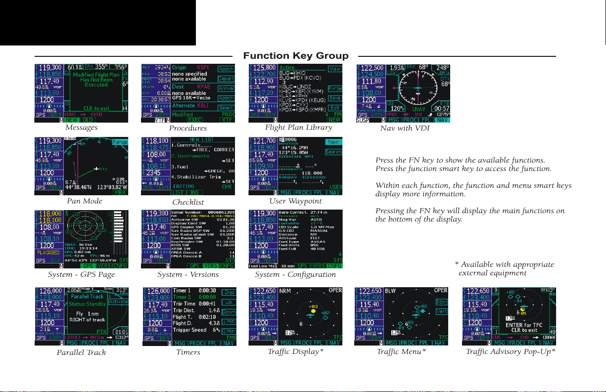
Recall (RCL) ...................................................... 46
Recent ............................................................... 46
User .................................................................. 47
Emergency ........................................................ 47
Flip/Flop ........................................................... 47
Signal ................................................................ 47
Weather ............................................................. 47
Audio ................................................................ 48
Save Channel..................................................... 48
Nav Radio (VOR) .................................................. 49
DME Distance ................................................... 49
ID ................................................................... 49
Monitor (MON)................................................. 49
Page 7

Introduction
Recall (RCL) ...................................................... 50
Flip/Flop ........................................................... 50
ID/To/Fr ............................................................ 50
Back Course ...................................................... 50
Audio ................................................................ 50
User .................................................................. 50
Save Channel..................................................... 50
Test Log ............................................................. 51
Transponder Control (XPDR) ................................ 52
Ident ................................................................. 52
Standby ............................................................. 52
ON ................................................................... 52
ALT ................................................................... 52
Transponder Line Selection Keys ....................... 52
Emergency .................................................. 52
VFR ............................................................. 53
TrgrSpd ....................................................... 53
Auto ............................................................ 53
Flight ID ..................................................... 53
Ground ....................................................... 54
Manually Select a Squawk Code ........................ 54
Flight Planning (FPL) ............................................ 55
Active Flight Plan ........................................ 55
Modified Flight Plan .................................... 55
Remote Flight Plan ...................................... 55
Library Flight Plan ...................................... 56
Flight Plan Functions ........................................ 56
View ............................................................ 56
Back ............................................................ 56
Edit ............................................................. 56
Expand (XPND) ......................................... 56
Cross Link (X-Link) ................................... 57
Remote Flight Plans ..................................... 57
Reverse (Rvrse) ........................................... 57
Save............................................................. 57
Edit ............................................................. 58
Execute (Exec) ........................................... 58
Comment (Cmnt) ....................................... 58
Copy .......................................................... 58
Discontinuity ..................................................... 59
Pilot Nav Legs ................................................... 59
Searching for Waypoints to Insert into a Flight Plan
................................................................... 60
Activate a Flight Plan ......................................... 61
Delete the Active Flight Plan.............................. 61
Edit a Flight Plan ............................................... 61
Changing Origin, Destination, & Alternate
Waypoints ............................................. 61
Inserting a Waypoint or Airway in Your Flight
Plan ....................................................... 61
Deleting a Waypoint or Airway in Your Flight
Plan ....................................................... 62
Steps for Setting Up a Simple Flight Plan........... 62
Steps for Setting Up a Flight Plan Using Terminal
Procedures and Airways .............................. 62
A. Set Origin, Destination, and Alternate
Waypoints ............................................ 63
B. Add a Standard Instrument Departure (SID)
Procedure .............................................. 63
C. Insert En Route Flight Plan Airways and/or
Waypoints ............................................. 64
D. Modifying a Flight Plan While In Flight . . 64
E. Add Arrival Procedures (STARS) ............. 65
F. Add Approach Procedures........................ 65
LEG TYPES ...................................................... 66
Turn Short Path Calculation ........................ 66
Procedures ........................................................... 75
Selecting Procedures .......................................... 75
Activating an Approach ..................................... 75
Steps for approach operations ..................... 76
Basic Approach Operations Examples ................ 76
Approaches with Procedure Turns ..................... 77
Flying the Procedure Turn ................................. 78
Flying the Missed Approach .............................. 80
Flying an Approach with a Hold ........................ 81
Flying a DME Arc Approach .............................. 84
Vectors To Final ................................................. 87
Flying a Vectored Approach ............................... 88
ILS Approaches ................................................. 90
Selecting an ILS Approach ........................... 91
Flying the ILS Approach .............................. 92
Selecting an LPV Approach................................ 96
Flying the LPV Approach ............................ 96
Flying the LP Approach ..................................... 97
LPV, LNAV/VNAV, LNAV+V, and LNAV Approaches
with Advisory Vertical Guidance ................. 99
Timers (TMR) .....................................................102
Timer 1 and Timer 2 ....................................... 102
Trip Time and Distance ................................... 102
Flight Time and Distance ................................. 103
Trigger Speed .................................................. 103
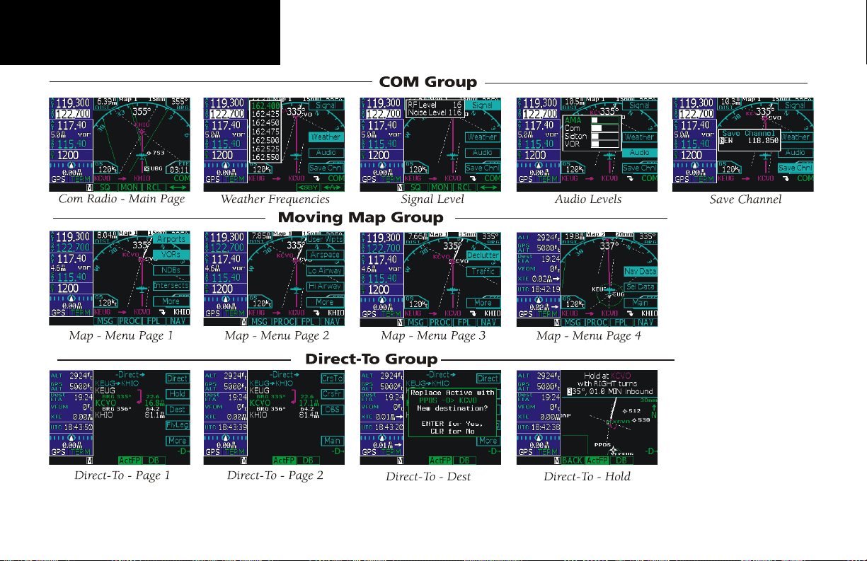
Checklist (CHK) .................................................. 104
v
Page 8

Introduction
Creating a New or Editing an Existing Checklist 1 0 4
Using Your Checklist ....................................... 104
Move a Checklist ............................................. 105
User Waypoints (USER) ...................................... 108
Creating or Editing a User Waypoint ............... 108
Searching for a User Waypoint ........................ 108
System Mode (SYS) ............................................ 109
GPS Status ....................................................... 109
Software Versions ............................................ 109
Configuration .................................................. 110
Barometric Correction ............................... 110
Barometric Pressure Units ......................... 110
Magnetic Variation Selection ...................... 111
Magnetic Variation Degree Value ............... 111
CDI Scale .................................................. 111
ILS CDI ..................................................... 112
Distance Units ........................................... 112
Altitude Units ............................................ 112
Fuel Type................................................... 113
Fuel Units ................................................. 113
Fuel Full Amount ...................................... 113
Fuel Low Message ..................................... 114
Display Brightness Selection ...................... 114
Minimum Brightness Value ........................ 115
Message Tone ............................................ 115
Airspace Alerts .......................................... 115
Owner Information ................................... 116
Aircraft Icon .............................................. 116
VFR Squawk ............................................. 116
Enable SBAS Providers ............................. 117
Parallel Track (PTK) ............................................118
Simulator Mode ................................................. 120
Automatic Track (ATK) .................................... 120
Manual Track .................................................. 120
Present Position (PPOS) .................................. 121
Airspeed .......................................................... 121
Messages (MSG) ................................................ 122
Text Messages .................................................. 122
Audio Messages .............................................. 126
Setting Message Audio Level...................... 127
Traffic (TFC) ........................................................ 128
Traffic Display Range Ring ............................... 128
Traffic Symbols ................................................ 128
Traffic Pop-Up ................................................. 129
No-Bearing Traffic Advisories (Skywatch Only) 129
Vertical Display Modes .................................... 130
Operate/Standby ............................................. 130
Test ................................................................. 130
Traffic in Map Mode ........................................ 131
Traffic Annunciations ...................................... 131
Specifications .................................................... 132
Physical Specifications ..................................... 132
Power .............................................................. 132
Environmental ................................................. 132
GPS Performance............................................. 132
VHF Comm Performance ................................ 132
VOR Performance ............................................ 132
Localizer Performance ..................................... 132
Glideslope Performance ................................... 132
Care Information .............................................. 133
Cleaning the Unit ............................................ 133
Battery Replacement ........................................ 133
Display Backlight............................................. 133
Appendix ..........................................133
Garmin Data Cards ............................................ 134
Installing and Removing Data Cards ................ 134
Glossary ............................................................. 136
WAAS ................................................................. 143
Safety Information ............................................ 143
What is WAAS? ............................................... 143
Safety Information ........................................... 143
Compliance, License, and Warranty Information 1 4 4
FCC Compliance ............................................. 144
Software License Agreement ............................ 145
Product Registration and Support .................... 145
Limited Warranty ............................................ 146
Index ................................................. 148
vi
Page 9
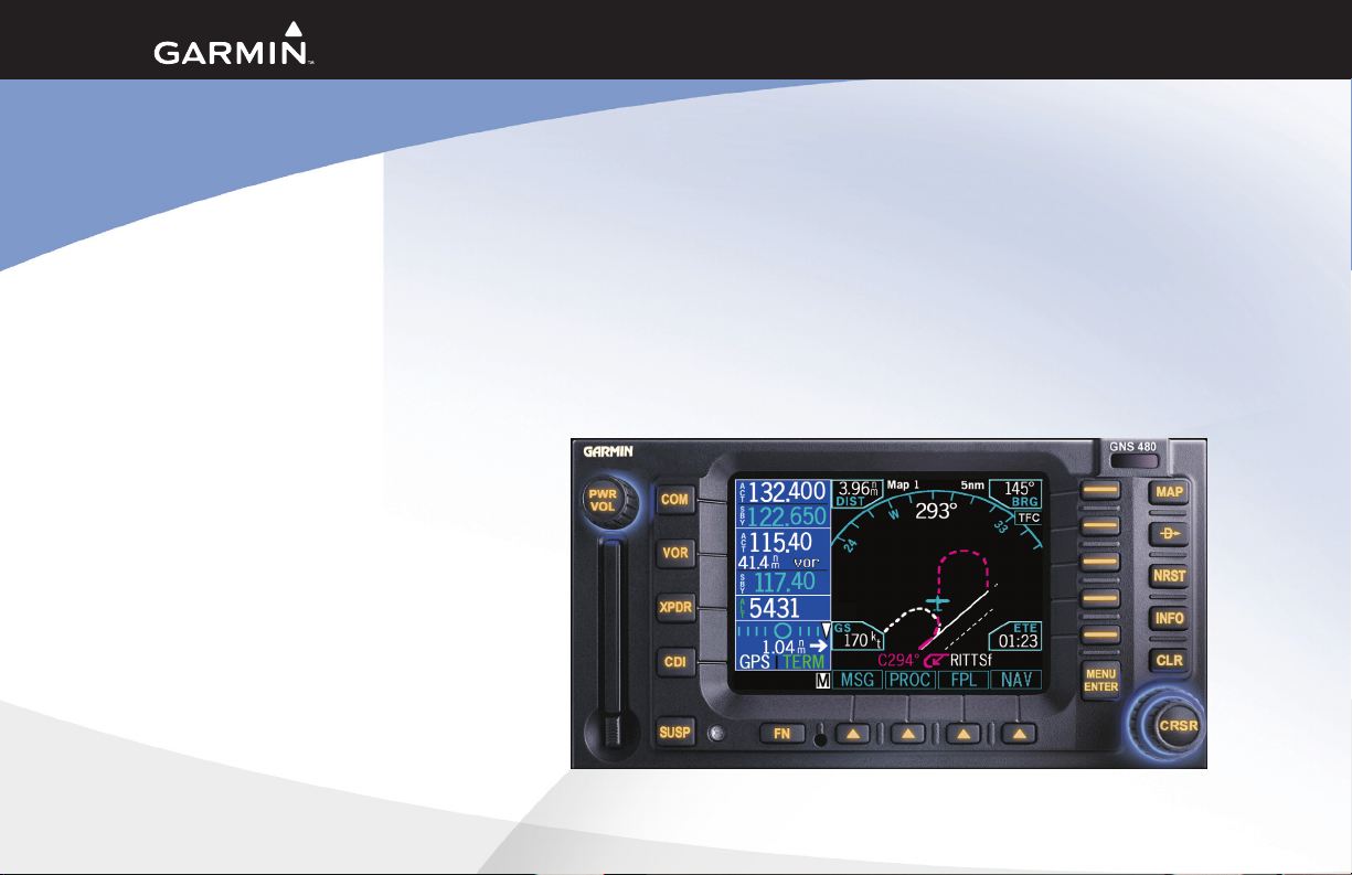
This guide describes the operation of the GNS 480 (CNX80) Color GPS/WAAS NavCom. The GNS 480
(CNX80) provides a new, higher level of accuracy, integrity, integration, flight planning capability, and convenience for the pilot. The GNS 480 (CNX80) combines a large number of easily accessible controls to use the
high-resolution color multi-function display, Nav and Com transceivers, GPS/WAAS navigator, and transponder controller all in a single unit. The GNS 480 (CNX80) with the GPS/WAAS navigator is certified for use as
primary navigation equipment for both VFR and IFR operations.
This Pilot’s Guide covers the details, so you can get the most out of your GNS 480 (CNX80), quickly. For more
details and examples, refer to the GNS 480 (CNX80) Computer-Based Training (CBT) compact disc and in-
ightdemoDVDwhichareprovidedforyourconvenience.ThesedocumentsandtheQuickReferenceGuide,
when used with the simulator for practice, will prepare you to get the most out your equipment.
Getting Started
1
Page 10
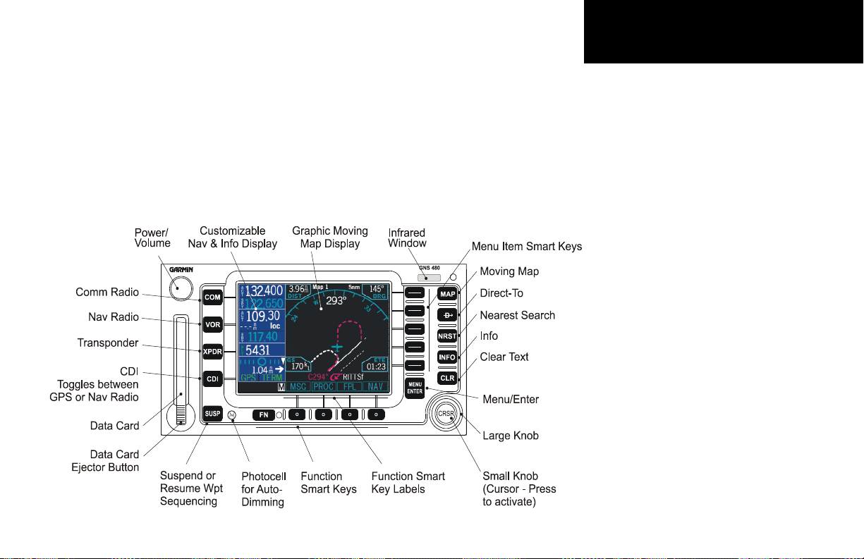
Getting Started
Push the PWR/VOL knob in to turn the unit on. Press
the COM, VOR, XPDR keys to activate that mode. Press
CDI to select the CDI source. Press SUSP to suspend
waypoint sequencing.
Press the “smart” key below the function label to activate the named function. Pressing FN scrolls available
functions.
2
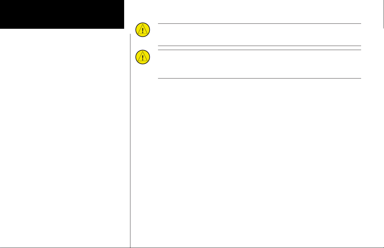
Controls
Power/Volume
The knob at the top left corner of the GNS 480 controls power on/off and the radio volume. Push the
PWR/VOL knob in to turn power on. Pull the knob out to turn power off. When the power knob is
pulled out, a time-out message and counter will appear for five seconds. Turning the knob will control the volume of the COM radio, unless the NAV radio is active then the NAV volume is controlled.
A white border surrounding the Com, VOR, and XPDR information will flash and the values you can
change will be highlighted when each mode is activated.
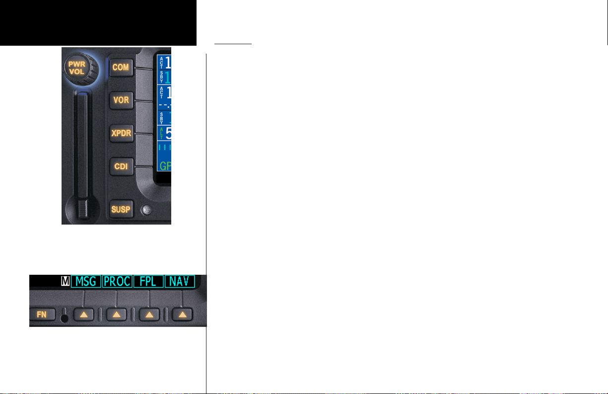
FN and Function Smart Keys
Press the FN key to page through the available group of Functions that appear at the bottom of the
display. The “Smart” function keys located below each label will activate that function.
COM
Select Com radio mode. Press COM. The function and menu item smart keys access more features.
VOR
Select Nav radio mode. Press VOR. The function and menu item smart keys access more features.
XPDR
Select the External Transponder mode, if installed. Press XPDR. The function and menu item smart
keys access more features.
CDI
Toggles the main CDI output between GPS and internal VOR/LOC radio sources.
SUSP
Manually suspends or resumes flight plan waypoint sequencing. When waypoint sequencing is
suspended, the SUSP annunciator will be displayed in the bottom left corner of the display. The GNS
480 will auto-suspend when required for certain procedures, such as Vectors-To-Final (VTF) mode. In
VTF mode, if you are within 45° of the inbound course and you are on the TO side, the “SUSP” mode
will turn off and return to normal sequencing. See page 99 for more details.
Page 11

MAP
Selects the moving Map mode. Press MAP twice to view Map page 1. Turn the Large knob to view all
four MAP pages. The function and menu item smart keys access more features.
Direct-To
Selects the Direct-To page. Menu options allow setting up Direct-To (D->), setting a customized
holding pattern around a waypoint (Hold), Course To (CrsTo) a waypoint, Course From (CrsFr) a
waypoint, OBS mode uses input from your CDI Course Selector, and activating a given leg of your
active flight plan (FlyLeg). The function and menu item smart keys access more features.
NRST
Activates Nearest Search. You can search through the closest 20 of airports, NDBs, VORs, intersections, airspaces, user-created waypoints, Flight Service Station (FSS) with frequency data, and Air
Route Traffic Control Center (ARTCC) with frequency data. The function and menu item smart keys
access more features.
INFO
Activates Info mode for the highlighted waypoint or the active flight plan (ActFP) waypoint. Information about the selected waypoint such as location, name, a map, frequencies, and more depending on
the waypoint type is provided. When frequencies are provided and highlighted, pressing the <-SBY
Press MAP to view the moving map. Press D-> to go
direct-to a selection. Press NRST to search for the
Nearest . Press INFO to view information about a
selected waypoint. Press CLR to clear information or
ignore a choice.
or <-A-> keys will insert the selected frequency into the appropriate radio. The function and menu
item smart keys access more features.
CLR
Clears text when editing or deletes the highlighted item.
Getting Started
3
Page 12
Getting Started
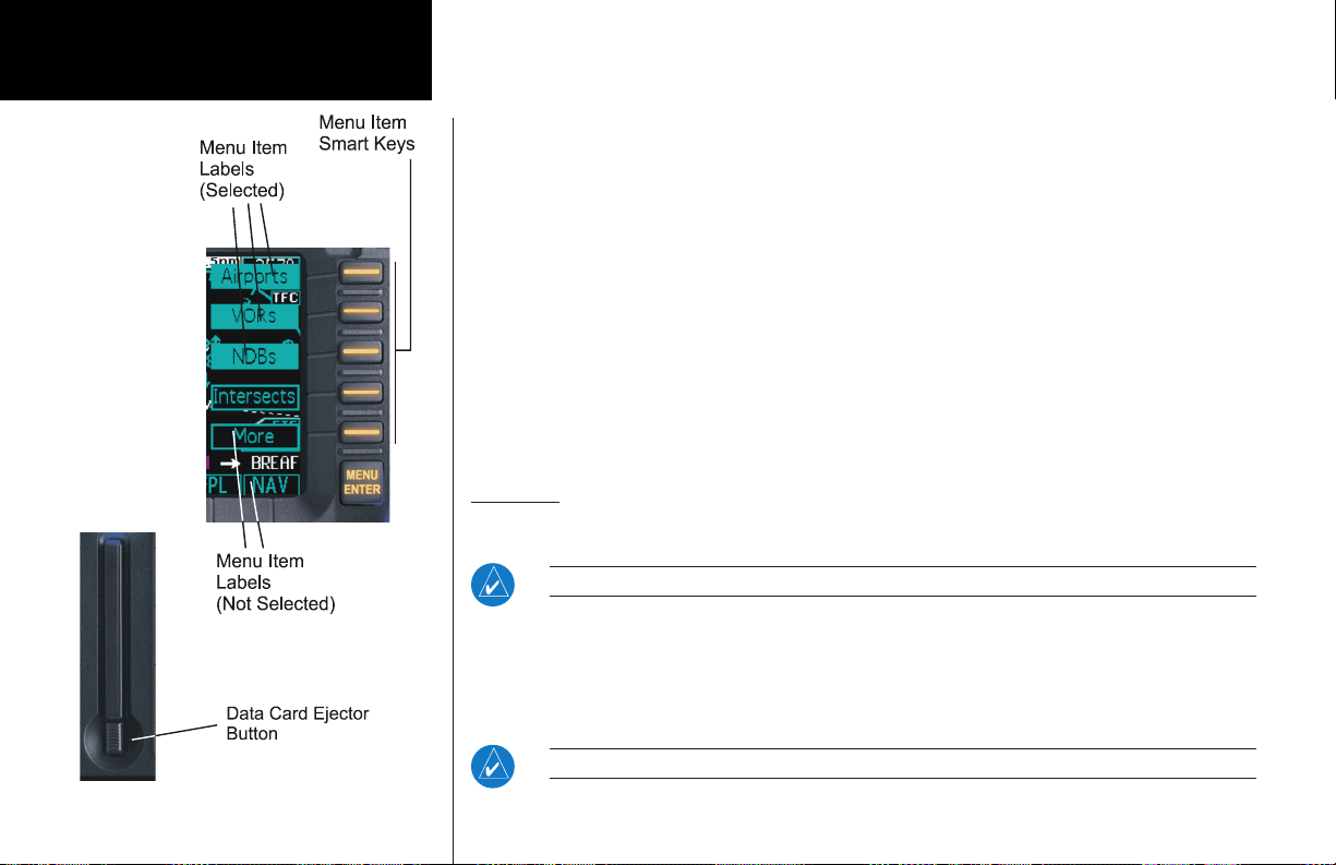
MENU/ENTER and Menu Item Keys
When editing information, or a response is required, pressing the Menu/Enter key accepts the value
or confirms the response. In COM, VOR, XPDR, and MAP modes, pressing this key will bring up a
list of menu items on the right side of the display allowing the pilot to select. The menu items are
then selected by pressing the key to the right of it. Pressing the Menu/Enter key while the menu
items are shown will remove them from view.
Large/Small Knobs
You can move the cursor or highlight information by turning the Large knob. Turn the Small knob
to change information.
CRSR
Press the Small knob in to activate the cursor (CRSR). The area on the display that you can now edit
will be highlighted. Now you can change information with the Small knob and move the cursor
to the next area to edit with the Large knob. If you are in Map mode, pressing the CRSR activates
PAN mode. In Transponder mode, it allows editing squawk codes. In Direct-To and Flight Plan (FPL)
modes, activating the CRSR control will help narrow a waypoint search.
Datacard
The Map database and other information is stored on a data card. The use of a data card allows you to easily
update information.
NOTE: Only change the data card when the power is turned off or you may damage your unit.
Handle your data card carefully. Do not touch the connector edge of the data card. To eject the card, press the
data card ejector. Gently pull the card straight out of the slot. Insert a data card by pushing the card straight into
the slot. When fully inserted, the data card and eject button will be flush and slightly recessed into the bezel.
When contacting your dealer or the Garmin customer service staff, eject the data card and write down the
information shown on the label.
NOTE: Never insert or eject the data card with the power on.
4
Page 13
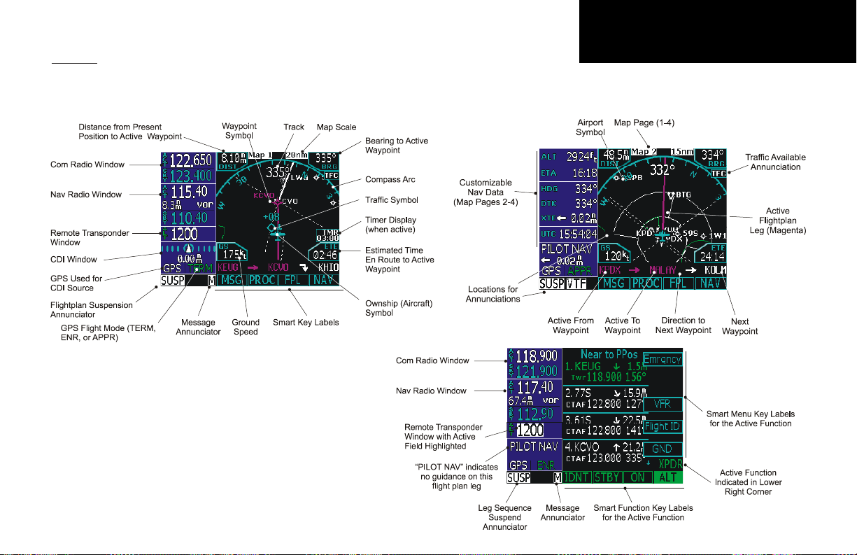
Display
The GNS 480 uses a high-resolution color display to provide information about the different functions. Information and “smart keys” unique for each mode of operation are displayed. Sample displays with a description
of common elements are shown below.
When you press the COM, VOR, or XPDR keys on the left side of the
display, the window for that function will be outlined and the information
active for editing will be highlighted.
The labels for the bottom row of Function smart keys will change for each
function selected. Press Menu/Enter to display Menu Item smart keys. The
Menu Item smart keys will adjust to the options for each function.
Getting Started
5
Page 14
Getting Started
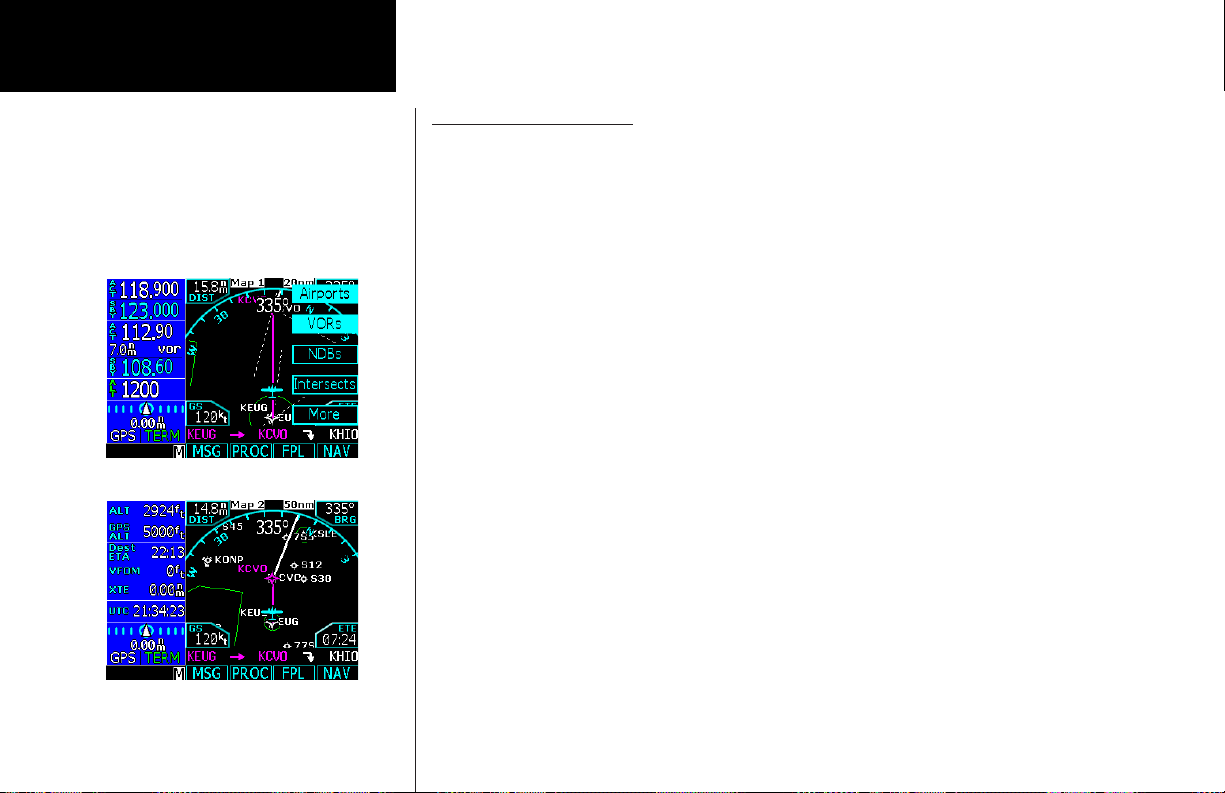
Using the Moving Map
The Map mode provides a moving map for a graphic display of your flight including the surrounding area,
as well as navigation information to aid your situational awareness. You can customize each of the four Map
pages for the Map range and the information displayed, such as Airports, VORs, NDBs, Intersections, User
Waypoints, Airspace, Traffic from TIS or Skywatch, Hi and Lo Airways, Flight Plan course line, or Nav information items. When decluttering is selected, the map is automatically decluttered to remove map detail for
clarity as you increase the map range.
1. Press MAP to reach Map mode. Radio, Nav, Transponder, CDI, Annunciator, or pilot-customized
information is shown on the left side of the display and the map display is shown on the right side.
2. There are four Map pages that you select by turning the Large knob.
3. Turn the Small knob to change the Map range. Map pages 2-4 allow you to customize the Nav display
items on the left side of the display and map display detail.
4. Press Menu/Enter to view the Menu items for the choices to customize your display.
5. Press the key next to the Menu item to change the item values.
6. Press the More key to go to the next page of Menu items.
6
Page 15
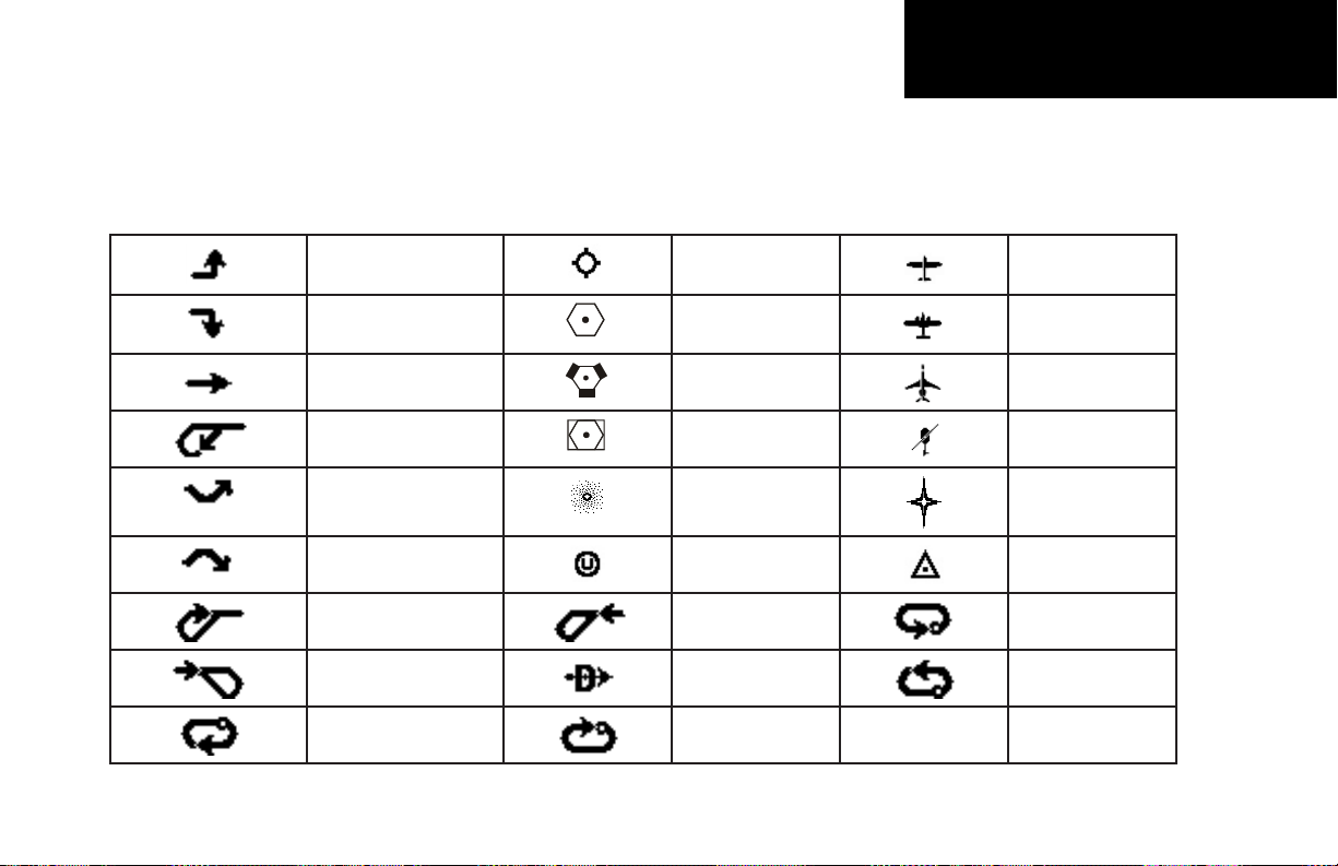
The following symbols are used on the map display to depict active legs of flight, waypoint types, and your aircraft.
Getting Started
Turn Left for next flight
plan leg
Turn Right for next
flight plan leg
No course change VORTAC Ownship - Jet
Left Procedure Turn
Outbound
Arc to the Left NDB Flight Plan
Arc to the Right User Waypoint Intersection
Left Procedure Turn
Inbound
Entering Procedure Turn
Right
Right Hand Holding
Pattern Outbound
Airport Ownship - Single
VOR Ownship - Twin
VOR-DME Ownship -
Helicopter
Waypoint
Entering Procedure
Turn Left
Direct-To Left Hand Holding
Right Hand Holding
Pattern Inbound
Left Hand Holding
Pattern Inbound
Pattern Outbound
7
Page 16
Getting Started
8
Page 17
Getting Started
9
Page 18
Getting Started
10
Page 19

Annunciations
The following annunciations appear on the appropriate displays to provide status or information. All annunciations
are available on the moving map display. Annunciations may be output to external annunciators.
Annunciation Description
GPS Indicates GPS is being used as the navigation source. Appears in lower left corner of the display.
VOR/ILS/LOC Indicates VOR/ILS/LOC is being used as the navigation source. Appears in lower left
corner of the display.
ENR Appears to the right of the “GPS” annunciator when in En Route mode. When > 30 nm
from departure or destination and not on departure or arrival procedure. CDI resolution
is ± 2 nm.
TERM Appears to the right of the “GPS” annunciator when performing approach navigation
within 30 nm of departure or arrival airport. CDI resolution is ± 1 nm.
APPR Appears to the right of the “GPS” annunciator when GPS approach is active, and on Final
Approach course (i.e. VTF or FAF, MAP, or the first Missed Approach waypoint is active. CDI
resolution is variable for all approaches and becomes more sensitive as you near the runway.
LOI “LOI” (Loss of Integrity) appears on the left side of the map display when WAAS/GPS is
unable to calculate the integrity of the position or calculated integrity is insufficient to
support the current phase of flight.
BC The Back Course annunciation appears to the right of “LOC” when the Back Course
Localizer mode is enabled.
DR The Dead Reckoning annunciator appears on the left side of the map display when GPS
position is unavailable and the GNS 480 is in Dead Reckoning mode. Dead Reckoning
mode will continue until GPS position is restored or the first Pilot Nav leg is reached.
PTK The Parallel Track annunciator appears in the lower left corner of the display when paral-
lel track is active.
SUSP Suspend annunciation appears in the lower left corner of the display when automatic
sequencing of waypoints in the active flight plan is suspended.
Getting Started
11
Page 20

Getting Started
M Message annunciation appears in the lower left corner of the display when a message is
VTF Vector To Final annunciation appears in the lower left corner of the display when “Vector
ALT Appears for Lnav/Vnav or LPV approaches when the aircraft’s estimated height is lower
CDI Window Shows course deviation, heading, or PILOT NAV.
CDI Window:
Rwy Dist/Brg
CDI Window:
FLAGGED
CDI Window:
HDG xx°
CDI Window:
PILOT NAV
TFC, TFC Fail, TFC STBY,
TFC Test, TFC N/A
LPV, LP, Lnav/Vnav, Lnav,
Lnav+V
available for viewing. A blinking “M” indicates a new message.
To Final” approach mode is active, which may be activated manually or automatically.
than the Final Approach waypoint height by more than the current VPL plus 50 meters.
Shows distance To runway and a bearing direction indicator for LPV, LNAV, and Lnav/
Vnav approaches.
No active guidance is available for the selected Nav source (VHF Nav radio or GPS
receiver). For GPS, the usual causes are Loss of GPS position, Loss Of Integrity, or inadequate GPS HPL or VPL on the Final Approach leg.
Displayed when a PILOT NAV Heading Leg is the active flight plan leg. The current heading is shown. If heading information is not available, the field is dashed.
Guidance is not provided on this leg by the GNS 480. Use other flight instruments to fly
this leg.
Status of the external traffic source.
LPV is for GPS precision approaches. Amber indicates the current vertical (VPL) or
horizontal protection level (HPL) exceeds the alarm limit. Green indicates the VPL and
HPL are acceptable for LPV or Lnav/Vnav approaches (WAAS environment). LP indicates
Localizer Performance with no vertical guidance. LPV indicates Localizer Performance
with vertical guidance. Lnav/Vnav indicates an Lnav approach with vertical guidance.
Lnav indicates an Lnav only approach with no vertical guidance.
Note that some Lnav/Vnav approaches are not yet marked in the database as such and
will show up as Lnav+V. Non-precision GPS approach with advisory vertical guidance. If
the chart shows the approach as Lnav/Vnav, it can be flown to Lnav/Vnav minimums.
12
Page 21

Starting Up
The GNS 480 performs internal checks and shows the status of the tests during start up. The startup screen,
owner name (if entered), testing, position, and database information shows on the screen for several seconds
and then shows the first Map page. It is not generally necessary to enter a GPS seed position unless the unit
has either been moved several hundred miles or been unused for six months or so with the power off. A seed
position should have been entered the first time the unit was turned on during installation.
Power Up
1. Push the PWR/VOL knob in to turn on power.
2. When the position display appears, you can press CHG to manually enter your present position or just
wait a few seconds for the GNS 480 to establish your position.
3. The GNS 480 performs a number of tests at startup to ensure proper operation. You may press SKIP to
bypass the startup tests, however, completing these tests is required for IFR flight. Any failures will be
noted by a message.
Set Fuel Full and Reserve
If a Fuel/Air Data Computer is installed, Fuel Full and Fuel Reserve amounts are entered manually in the Configuration page of System mode and are reflected in the start-up screens. On start-up, you will be prompted for
the Total Fuel on Board.
Press the Menu/Enter key to accept the displayed amount of fuel or change the displayed amount with the
Small knob and then press the Menu/Enter key.
Self-Tests
The GNS 480 performs internal checks and shows the status of the tests during start up. After these internal
checks, the GNS 480 is ready to navigate.
Getting Started
Start-Up Display
Database Check
The GNS 480 verifies the integrity and expiration date of the database. Up to two database cycles are supported. The GNS 480 will load the appropriate current database cycle and also let you know if a database is
not current (dates invalid).
Database Verification
13
Page 22
Getting Started
The database information can be checked after start-up in the SW Version page of the System function. Press
the Menu/Enter key to continue after you have verified the dates. Valid databases are in green. The database
beingusedhasanasterisk(*)nexttoit,iftherearetwodatabases.Expireddatabasesareamber.
View Checklists
Use a checklist to review preparation for flight.
1. Press FN and then the CHK function smart key.
2. Turn the Large knob to select the desired list and press Menu/Enter.
3. Press CHCK or Menu/Enter as you check each item on the list. The next item in the list will then be
highlighted. Checking the last item will take you back to the main Checklist page.
View Messages
You can review system messages by pressing the MSG function smart key. Turn the Large knob to switch
between New and Old messages. Turn the Small knob to scroll through the available messages. The Message
annunciator (M) will flash until all unread messages have been read. While old messages exist and there are
no new messages, the Message annunciator will remain solid. The Message annunciator will not appear when
there are no messages.
Set Com and Nav Frequencies
You can set the Com and Nav frequencies manually
1. Press Com for VHF Com frequencies or press VOR for VOR/LOC/ILS frequencies.
2. Turn the Large knob to select MHz and turn the Small knob for kHz of the stand-by frequency.
3. Press the <—> key to flip-flop the active and stand-by frequencies.
4. Press MON to toggle monitoring of the stand-by frequency.
5. Turn the PWR/VOL knob to adjust the audio level.
14
Page 23
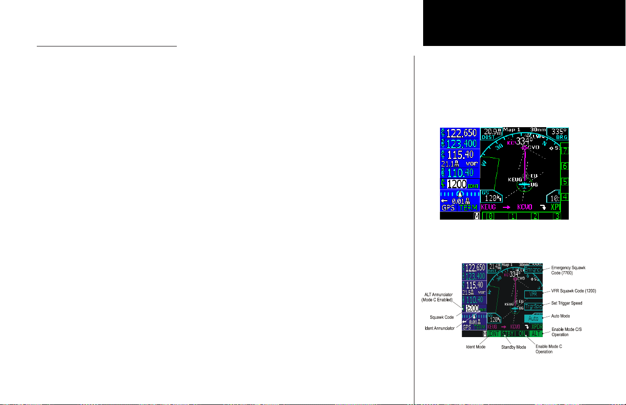
Using the Remote Transponder
The Transponder Control Mode will allow you to control a compatible remotely mounted transponder from
the GNS 480 front panel.
Press XPDR to activate Transponder mode.
Change the Transponder (Squawk Code) - Two Methods
1. Turn the Large knob to highlight the Squawk Code.
2. Turn the Small knob to select a number and then turn the Large knob to move to the next character.
3. The Ident is automatically saved after selecting the fourth character.
OR
1. Press the Cursor (CRSR) knob in.
2. Press the function or menu item smart keys next to the numbers 0-9 shown on the bottom and right
side of the display in the order desired.
3. The Ident is automatically saved after selecting the fourth character.
Transponder Options
Press Menu/Enter to view options. Controls and features may vary depending on the transponder.
• PresstheEmrgncy menu item key and then Menu/Enter to insert the 7700 squawk code.
• PresstheVFR menu item key to insert the 1200 squawk code.
• PresstheTrgrSpd menu item key to select the speed that will “trigger” the automatic activation of the
transponder (SL70 only) when in Auto mode.
1. Turn the Large and Small knobs to select the trigger speed.
2. Press Menu/Enter to save the trigger speed.
• PressAuto to toggle the Auto Activate mode. The transponder (SL70 only) automatically goes from
standby to active when accelerating past the Trigger Speed and goes from active to standby when
decelerating below the Trigger Speed.
• PressIDNT to activate Ident mode.
• PressSTBY to place the transponder in Standby.
• PressON to enable Mode A operation (sends a squawk code).
• PressALT to enable Mode C/S operation (sends a squawk code and altitude data).
Getting Started
Changing the transponder squawk code
Transponder details
15
Page 24
Getting Started
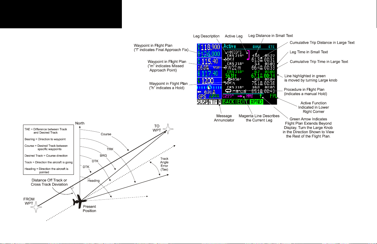
Nav Terms Diagram
Flight Plan Terms Diagram
16
Page 25

Create a New Flight Plan (Quick Method)
The Flight Planning function lets you set up and store flight plans where you can name the flight plan, insert a
series of waypoints, and then add comments. The Active flight plan is the flight plan that the GNS 480 is currently
using for navigation guidance. The Modified flight plan is a temporary copy of the active flight plan that you can
edit prior to executing or saving the changes. The active plan won’t be affected until you execute the modified plan.
A remote flight plan is one that has been received from another connected GNS 480, but while the units are not
setup for Cross-Link (X-Link) mode. The Library flight plans are stored flight plans for future use. This is a quick
start overview of flight planning. See the Flight Planning section for more detail.
1. Press FN and then the FPL function smart key.
2. Press New.
3. Use the Large and Small knobs to select the Origin waypoint and then press Menu/Enter.
4. Use the Large and Small knobs to select the Destination waypoint and then press Menu/Enter. This
allows you to select the appropriate terminal procedures from the database. The active flight plan is
deleted and is replaced with the new Direct-To flight plan.
5. Highlight the departure waypoint and insert a waypoint or airway. Continue inserting waypoints or
airways until the route is complete.
6. The flight plan is automatically saved into the Library and named by the Origin and Destination
waypoints.
7. Press the Exec key to execute the flight plan and make it the active flight plan.
Select a Direct-To a Waypoint in Your Flightplan
1. Press the D-> key.
2. Turn the Large knob to highlight a waypoint.
3. Press the Direct menu selection key.
Select a Direct To Waypoint Not in Your Flightplan
1. Press the D-> key and then the DB function smart key.
2. Select a waypoint using the Small knob to select a character and the Large knob to move to another
character.
3. Press the Direct menu item key.
Getting Started
Flying Direct-To a new destination
(Direct-To - DEST)
17
Page 26
Getting Started
Nearest waypoint search - Airport
(TWR/CTAF - Frequencies)
Nearest airport frequencies
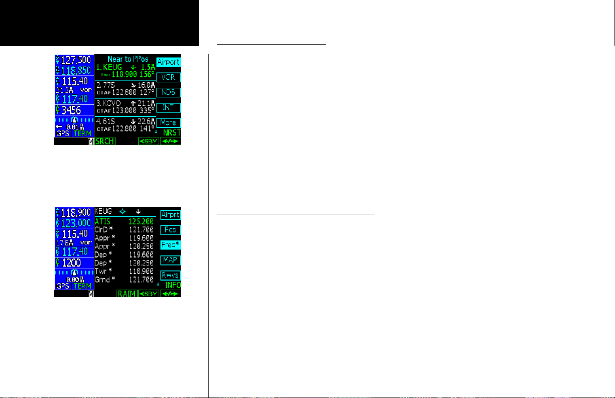
Find a Nearest Waypoint
The Nearest (NRST) Waypoint Search function allows you to search for the 20 waypoints nearest to your present position in each of eight waypoints types: Airport, VOR, NDB, INT, User, FSS (Flight Service Station), Airspace, and Air Route Traffic Control Center (ARTCC). You can also set Limits to select a range of airport types
to show up for the Nearest Airport type. You can then look up information about a waypoint or fly direct to it
1. Press NRST. The default waypoint type is Airport.
2. Press the menu item key for the desired waypoint type. Press the More menu item key to display more
types.
3. Turn the Large knob to scroll through the list.
4. Press the Standby (<-SBY) or Active (<-A->) smart keys to insert the frequency into the Com radio.
5. Press D-> to fly direct to the highlighted waypoint or press INFO to display information about that
waypoint.
6. Press the RAIM function key to perform a RAIM prediction.
Find a Nearest Waypoint Frequency
1. Press NRST and then press the menu item key for the desired waypoint type. Turn the Large knob to
highlight the desired waypoint.
2. If the desired frequency is shown in the Nearest list, press the Standby (<-SBY) or Active (<-A->) smart
keys to insert the frequency into the Com or Nav radios.
3. If you need another frequency for an airport, press INFO and then the Freqs menu item key.
4. Turn the Large knob to highlight the desired frequency.
5. If the frequency has an asterisk, press the Freq* menu item key to display more narrative information
about that frequency. Turn the Large knob to scroll through the narrative information of the other
frequencies.
6. Press <SBY to insert the selected frequency into the Standby position or press <A> to insert it into the
Active position in the Com or Nav radio.
18
Page 27

Inserting Terminal Procedures and Approaches
After creating your flight plan, you can select an approach, departure, or arrival procedure so the GNS 480 can
guide you through the flight plan. You may also make adjustments in Flight Edit mode.
1. Press the PROC function smart key for Procedure Mode. The Origin and Destination waypoint of your
active flight plan are shown.
2. Press the Depart menu item smart key to select the Departure procedure. If available, select the
departure runway (with the Small knob or the menu item keys).
3. Turn the Large knob to highlight the transition and turn the Small knob to make the selection. Press
Menu/Enter to accept the selections.
4. Press the BACK function smart key to return to the Procedures mode. Depending on the procedure for
your destination, press the Destination Arrival or Appch menu item smart key.
5. Choose the transition and the runway by moving to a selection with the Large knob and listing the
choices with the Small knob. Press Menu/Enter to accept the procedure.
6. If desired, select an alternate airport by pressing the Alternate Select menu item key.
7. Press EXEC to activate the procedures for your flight plan.
Setup procedures and approaches for your
flightplan
Perform a RAIM Prediction
RAIM prediction predicts if GPS coverage is available for any waypoint. This is used when WAAS satellites or
corrections are not available. If WAAS corrections are not available, vertical guidance will not be available for
an approach.
1. Highlight a waypoint in the active flight plan or select a waypoint from the database. Press INFO and
then press the RAIM function smart key when it is shown.
2. Press the CRSR knob in. One of the fields will be highlighted. Change the values of the Arrival Date
and/or Arrival Time (in UTC time) with the Small knob while moving to a value with the Large knob.
The default calculation is the ETA to the last waypoint in the active flight plan. When selecting a
waypoint from the database other than one in the active flight plan, the default calculation is the ETA
from the present position to the waypoint.
3. After setting the values, press the Menu/Enter key to compute the RAIM prediction.
Getting Started
Compute RAIM for your destination
19
Page 28
Basic Operation
Moving Map
Map Mode - Page 1
Moving Map Mode (MAP)
The Map mode provides a moving map for a graphic display of your flight including the surrounding area as
well as navigation information. Maps are generally drawn with Ground Track magnetic North at the top of the
display (Up). You can customize each of the four Map pages for the Map scale and the information displayed,
such as Airports, VORs, NDBs, Intersections, User Waypoints, Airspace, Traffic, Hi and Lo Airways, Flight Plan
course, or Nav items. Other information is available depending on equipment installation and services.
1. Press MAP to reach Map mode. Radio, Nav, Transponder, CDI, Annunciator, or pilot-customized
information is shown on the left side of the display and the map display is shown on the right side.
2. There are four Map pages that you select by turning the Large knob.
3. Turn the Small knob to change the Map scale. Map pages 2-4 allow you to customize the Nav display
items on the left side of the display and map display detail.
4. Press Menu/Enter to view the Menu items for the choices to customize your display.
5. Press the key next to the Menu item to control the display of information.
6. Press the More key to go to the next page of Menu items.
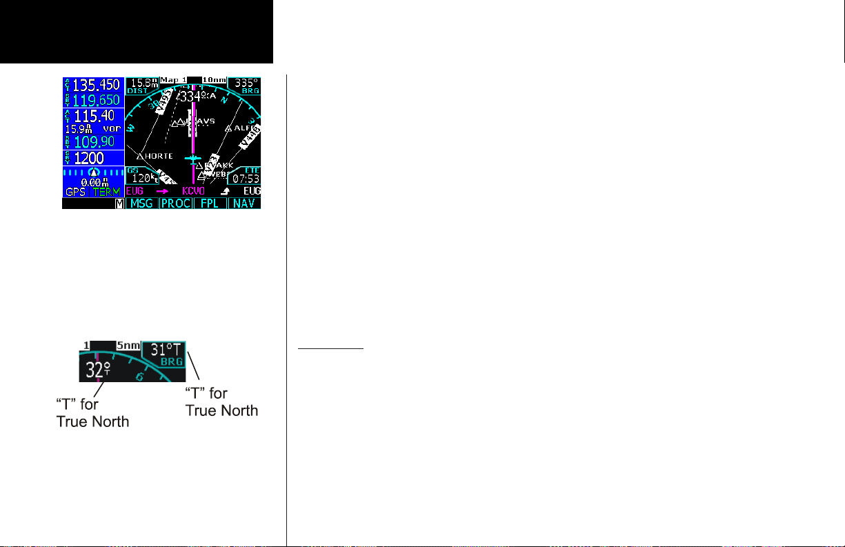
True North
The Map can be referenced to True North after setting the Magnetic Variation to 0° in the Configuration section
of System mode. When set to True North, the degree values on the map display will show a “T” along with
the degree symbol. Magnetic North is used for normal operation and is not indicated. In some situations, True
North may be used such as in northern Canada.
True North indication in Map Mode
20
Page 29
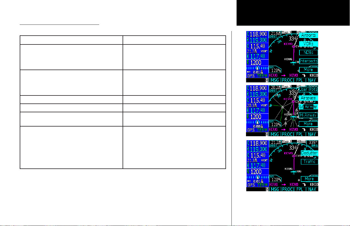
Moving Map Mode Menu Items
Menu Item Description
Airports, VORs, NDBs, Intersections, User Waypoints,
Lo and Hi Airways
Airspace Solid reversed means the airspace outline and sector
Traffic Toggles on/off the display of traffic when it is installed.
Flight Plan Map pages 2-4. Toggles display of route line on/off.
Declutter Auto-Declutter - Toggles decluttering of the display of
Nav Data/Sel Data Customize the Nav information on map pages 2-4.
Solid reversed label means identifier and location
symbol are displayed. A bold outline means only the
location symbol will be displayed. A thin outline means
this item will not be displayed on the map.
lines are displayed. A bold outline means that only the
outline of airspace is displayed. A thin outline means
that airspaces will not be displayed on the map.
labels and icons on/off at the higher zoom levels.
Press the Nav Data key and then the Sel Data key.
Then turn the Large knob to move the cursor to the
different fields in the Nav information part of the Map
display. Turn the Small knob to view the available
choices of information. Press Menu/Enter to confirm
and save your choices.
Basic Operation
Moving Map
21
Page 30
Basic Operation
Moving Map
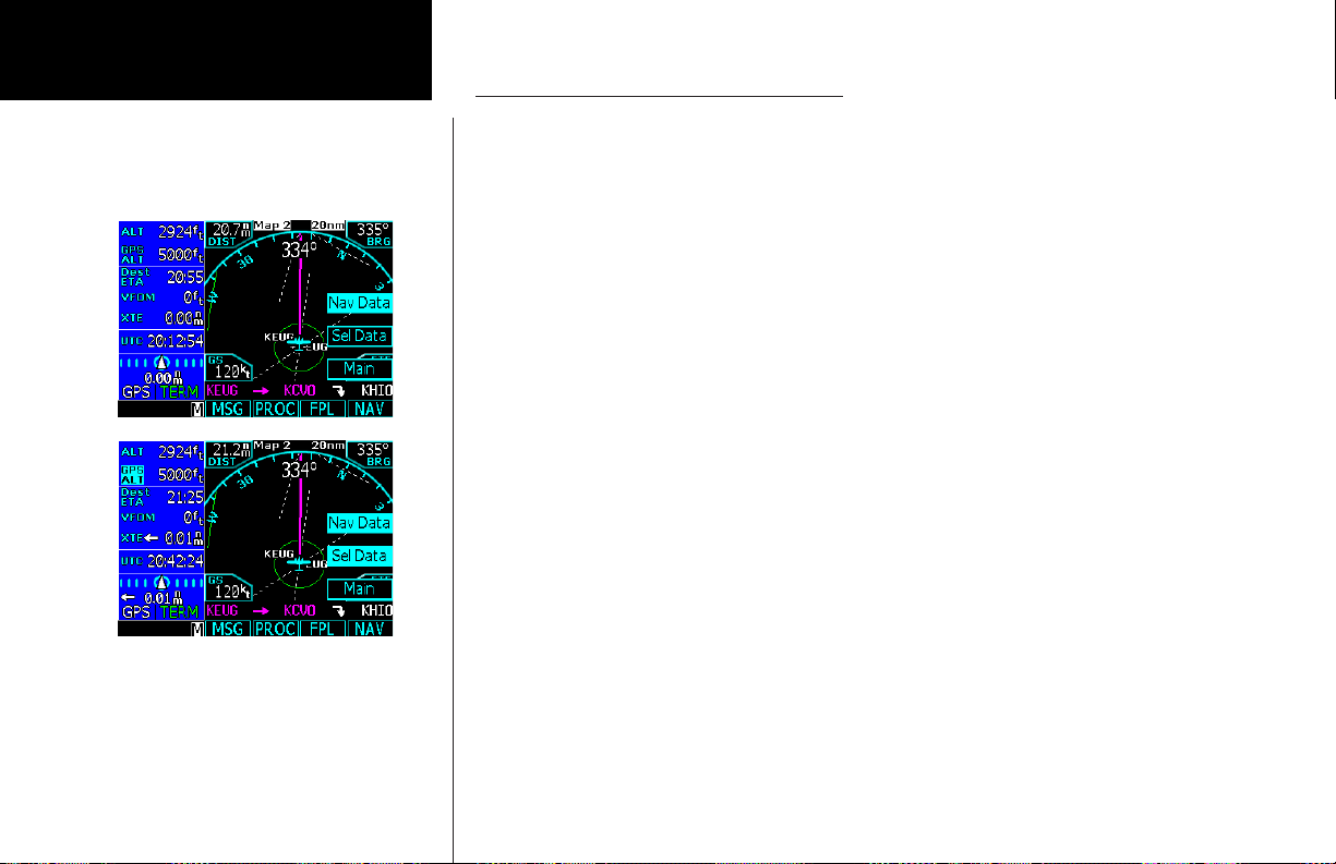
GNS 480 Map Mode Nav Data Options
The following table shows the choices of the options you can make for setting up the Map Mode display in
your GNS 480. You can customize the Nav information displayed on the left side of the display for Map Mode
pages 2, 3, and 4. You can select these options as described below.
1. Press MAP to reach Map mode.
2. Turn the Large knob to select pages 2-4. You can’t change the Nav information options for page 1.
3. Press the Menu/Enter key.
4. Press the More selection key until the Nav Data selection is available.
5. Press the Nav Data menu item key.
6. Press the Sel Data menu item key to activate selection of options of Nav Data information.
7. Turn the Large knob to highlight the desired Nav Data item. Turn the Small knob to change the
displayed option.
8. Press Menu/Enter when you have completed your selections.
9. If desired, turn the Large knob to another Map Mode page and customize that page.
22
Page 31

Selectable Nav Data Fields for Map Pages 2-4
Option Name Abbrev. Description Units
Basic Operation
Moving Map
Altitude ALT Baro-corrected pressure altitude.
Value is dashed out when there is no
valid source.
Bearing BRG Bearing to station for the active
waypoint. If the active leg is a pilot
nav leg or heading leg, or position is
invalid, this will be dashed.
Cabin Pressure Cab Prs The current cabin pressure value
when an external carbon monoxide is
installed. Not selectable if CO Guardian is not configured. Note: Cabin
pressure alerting is not supported.
Cabin
Temperature
CO Level CO Lvl The current carbon monoxide (CO)
Cab Tmp The current cabin temperature value
when an external carbon monoxide is
installed. Not selectable if CO Guardian is not configured.
level inside the cabin when an
external carbon monoxide is installed.
Not selectable if CO Guardian is not
configured.
Feet (ft) or meters (m) at whole unit
resolution.
0 to 359 degrees at 1-degree resolution.
Feet (ft) or meters (m) in whole units.
In degrees Celsius (ºC).
ppm (parts per million)
23
Page 32

Basic Operation
Moving Map
Selectable Nav Data Fields for Map Pages 2-4
Option Name Abbrev. Description Units
Estimated
Time of
Arrival at Final
Destination
Estimated
Time
En Route to
Final
Destination
24
Dest ETA The estimated time of arrival to the
final destination waypoint is based
upon ground speed. If the active leg is
not part of the flight plan (ie direct-to
outside flight plan), ground speed
is less than or equal to five knots, or
position is invalid, this will be dashed.
Dest ETE The estimated time en route to the
final destination waypoint using the
same information as the Dest ETA
field except it is calculating the time
en route. If the active leg is not part of
the flight plan (ie direct-to outside the
flight plan), ground speed is less than
or equal to five knots, or position is invalid, this will be dashed. If the current
leg is a pilot nav leg, OBS or heading
leg, this value will be dashed.
Hours and minutes, 00:00 to 23:59,
based on a 24 hour clock
Hours and minutes, 00:00 to 99:59
and when less than 1 hour away, minutes and seconds 00:00 to 59:59.
Page 33

Selectable Nav Data Fields for Map Pages 2-4
Option Name Abbrev. Description Units
Basic Operation
Moving Map
Estimated Fuel
Remaining at
Final
Destination
Distance DIST This is the distance to the next
Distance to
Destination
Dest FUEL
REM
DIST TO Dest This is the distance to the end of
The estimated fuel remaining at the
final destination waypoint using the
flight plan information estimated
fuel flow, and ground speed. If the
active leg is not part of the flight plan
(ie direct-to outside the flight plan),
ground speed is less than or equal to
five knots, or position is invalid, this
will be dashed. If the current leg is a
pilot nav leg, OBS or heading leg, this
value will be dashed.
waypoint. If the current leg is a pilot
nav leg or heading to manual termination, then the distance is dashed.
If the position is invalid, then the
distance is dashed.
the flight plan. If a leg is not to a
waypoint or is a pilot nav leg, then
the distance is be estimated. If the
current leg is a pilot nav leg, OBS or
heading leg, the distance is dashed. If
the position is invalid, then the distance is dashed. If the active leg is not
part of the flight plan (i.e. direct-to
outside flight plan), it is dashed.
0.0 to 99999.9 US gallons (usg), Imperial gallons (img), liters (L), pounds
(lbs), or kilograms (kg) at tenths of
unit resolution
Nautical miles (nm), statute miles
(sm), or kilometers (km). 0.00 to
9.99 units at 0.01 unit resolution,
10.0 to 99.9 units at 0.1 unit resolution, and 1 unit resolution otherwise.
Nautical miles (nm), statute miles
(sm), or kilometers (km). 0.00 to
9.99 units at 0.01 unit resolution,
10.0 to 99.9 units at 0.1 unit resolution, and 1 unit resolution otherwise.
25
Page 34

Basic Operation
Moving Map
Selectable Nav Data Fields for Map Pages 2-4
Option Name Abbrev. Description Units
Desired Track DTK This is the current DTK to the active
waypoint. If the current leg is a pilot
nav leg or heading leg, or position is
invalid, then the DTK will be dashed.
Estimated
Time of Arrival
Estimated
Time En Route
Fuel
Endurance
26
ETA The estimated time of arrival is to
the active waypoint. It does not give
consideration for a curved path. If
the active leg is a pilot nav leg or to
a manual termination (unless FM or
HM leg), ground speed is less than
or equal to five knots, or position is
invalid, this will be dashed.
ETE The estimated time remaining en
route to the active waypoint. It does
not give consideration for a curved
path. If the active leg is a pilot nav leg
or to a manual termination (unless
FM or HM leg), ground speed is less
than or equal to five knots, or position is invalid, this will be dashed.
FUEL ENDUR Fuel endurance is calculated from the
fuel remaining and the current flow
rate. Value is dashed out when there
is no valid source. Not selectable if
Fuel or FADC is not configured.
0 to 359 degrees at 1-degree resolution.
Hours and minutes, 00:00 to 23:59,
based on a 24 hour clock.
Hours and minutes, 00:00 to 99:59
and when less than 1 hour away, minutes and seconds 00:00 to 59:59.
Hours and minutes, 00:00 to 99:59.
Page 35

Selectable Nav Data Fields for Map Pages 2-4
Option Name Abbrev. Description Units
Basic Operation
Moving Map
Fuel Flow FUEL FLOW
L or R
Fuel
Remaining
Estimated
Fuel to Final
Destination
FUEL REM For FADC that provide fuel remaining,
FUEL TO Dest The estimated fuel used to reach the
Fuel flow is displayed on a per engine
rate for twin engines (L and R) or single
engine rate (no L or R). Value is dashed
out when there is no valid source. Not
selectable if Fuel or FADC is not
configured.
the GNS 480 shall use the report value
from the FADC. For FADC that do
not provide fuel remaining, the GNS
480 will calculate the fuel remaining
from the initial fuel entered at start-up
subtracting fuel used. Value is dashed
out when fuel used information is not
available. Not selectable if Fuel or
FADC is not configured.
final destination waypoint using the
flight plan data like Dest FUEL REM
does. If the active leg is not part of the
flight plan (i.e. direct-to off the flight
plan), ground speed is less than or
equal to five knots, or position is invalid, this will be dashed. If the current
leg is a pilot nav leg, OBS or heading
leg, the distance will be dashed.
0.0 to 9999.9 US gallons (gph), Imperial gallons (gph), liters (lph), pounds
(pph), or kilograms (kph) per hour at
tenths of unit resolution.
0.0 to 99999.9 US gallons (usg), Imperial gallons (img), liters (L), pounds
(lbs), or kilograms (kg) at tenths of
unit resolution.
0.0 to 99999.9 US gallons (usg), Imperial gallons (img), liters (L), pounds
(lbs), or kilograms (kg) at tenths of
unit resolution.
27
Page 36

Basic Operation
Moving Map
Selectable Nav Data Fields for Map Pages 2-4
Option Name Abbrev. Description Units
Fuel to
Waypoint
GPS Altitude GPS ALT If available, this provides GPS altitude,
GPS Vertical
Rate
Ground Speed GS The ground speed of the aircraft. Value
Heading HDG The direction the nose of the aircraft
28
FUEL TO
WPT
GPS VS If available, this provides GPS-based
Fuel to the next waypoint will be calculated given the current fuel flow rate
and the ETE to the waypoint. If the
active leg is not part of the flight plan
(ie direct-to outside the flight plan),
active is a pilot nav leg, active leg is
to manual termination, ground speed
is less than or equal to five knots, or
position is invalid, this will be dashed.
referenced to MSL. Note that this
altitude will not be the same as barocorrected altitude, when airborne.
vertical speed.
is dashed out when position is invalid
or ground speed less than 5 kts.
is pointing. This requires a heading
input via an ADC or HSI bootstrap.
.0 to 99999.9 US gallons (usg), Imperial gallons (img), liters (L), pounds
(lbs), or kilograms (kg) at tenths of
unit resolution.
Feet (ft) or meters (m) in whole unit
resolution
Feet/minute (ft/m) or meters/minute
(m/m). Shall support at least range
of -9999 units to 9999 units. Value
shall be rounded to 10 unit resolution
Knots (kt), kilometers per hour (k/h),
or miles per hour (m/h). 0 to 999
units at 1 unit resolution.
0 to 359 degrees at 1-degree resolution.
Page 37

Selectable Nav Data Fields for Map Pages 2-4
Option Name Abbrev. Description Units
Basic Operation
Moving Map
Horizontal Fig-
ure of Merit
Minimum Safe
Altitude
Outside
Temperature
True Airspeed TAS The true airspeed is only available if
Track Angle
Error
Track TRK The aircraft’s ground track angle. Value
HFOM The current 95% confidence horizon-
tal accuracy value, as reported by the
GPS engine.
MSA The minimum safe altitude in the
aircraft’s present vicinity. This value is
dashed out if data is unknown or the
database is invalid.
OAT The current outside air temperature
value. This requires an FADC or CO
Guardian input.
an air data computer is providing it.
Value is dashed out otherwise.
TKE The Track Angle Error (TKE) is the
difference between the aircraft’s track
and desired track. TKE is followed by
an L or an R, indicating left or right
of DTK (if value is 0 or 180, then L/R
will not be displayed). Value is dashed
out if TRK or DTK is unavailable.
is dashed out if position is invalid.
Feet (ft) or meters (m) in whole unit
resolution.
Feet (ft) or meters (m) in whole unit
resolution.
Degrees Celsius (ºC)
Knots (kt), kilometers per hour (k/h),
or miles per hour (m/h). 0 to 999
units at 1 unit resolution.
0 to 180 degrees at one-degree
resolution.
0 to 359 degrees at 1-degree resolution.
29
Page 38

Basic Operation
Moving Map
Selectable Nav Data Fields for Map Pages 2-4
Option Name Abbrev. Description Units
Zulu Time UTC The current system time determined
from GPS if available. Time is displayed in UTC (Universal Coordinated
Time) using the 24-hour clock. Value
is dashed out if position is invalid.
Vertical Figure
of Merit
Wind WND Shown by a flag or arrow oriented for
Cross Track
Error
30
VFOM The current 95%-confidence vertical
accuracy value, as reported by the
GPS engine.
the wind with the wind speed to the
right. Value is dashed out if not available or unable to calculate internally.
XTE This is straight-line distance. Value is
dashed out if position is invalid.
Hours, minutes, and seconds,
00:00:00 to 23:59:59.
Feet (ft) or meters (m) in whole units.
Knots (kt), kilometers per hour (k/h),
or miles per hour (m/h). 0 to 999
units at 1 unit resolution.
Nautical miles (nm), statute miles
(sm), or kilometers (km). 0.00 to
9.99 units at 0.01 unit resolution,
10.0 to 99.9 units at 0.1 unit resolution, and 1 unit resolution otherwise.
Arrow pointing left before number
shall indicate that the plane is right
of course. Arrow pointing right after
number shall indicate that the plane is
left of course. No arrow is displayed
when value is 0.00.
Page 39

Nav/HSI Display (NAV)
The GNS 480 displays a track-based Horizontal Situation Indicator (HSI) view. The Nav function is reached
by pressing the NAV smart function key. The layout, annunciations, and nav data are similar to Map mode.
Distance to the destination is shown in the top left corner. Bearing to the destination is shown in the top right
corner. Current Ground Speed (GPS determined) is shown in the lower left corner. The Estimated Time En
Route from your current position to the next waypoint. You may also select the categories of Nav Data shown
on the left side of the display. When vertical guidance is provided, a vertical deviation indicator is shown on
the left side of the display. The CDI/VDI is driven by one of the following: GPS data if GPS CDI annunciation
is selected or Nav radio data if LOC, VOR, or ILS annunciation is selected.
The Nav/HSI function is useful for aircraft with autopilots that do not have roll steering capabilities.
When a Nav radio is driving the display, the needles
are green.
When the GPS receiver is driving the display, the
needles are magenta.
The CDI line will become thicker on full-scale or
off-scale deflection.
When Auto-switching is enabled in the System-Configuration function, the CDI source will automatically
switch from GPS to ILS.
Basic Operation
NAV / VDI
Nav Mode HSI Display With VDI
31
Page 40

Basic Operation
NAV / VDI
Selecting Displayed Nav Data
Information
1. Press the Menu/Enter key.
2. Press the Nav Data menu item key and
while it is highlighted press the Sel Data
menu item key.
3. While both Nav Data and Sel Data keys
are highlighted, you may now select Nav
Data items displayed on the left side of the
display.
4. Note that the top Nav Data item is
highlighted. Turn the Large knob to move
the highlight to other items. Turn the
Small knob to scroll through the available
Nav Data items.
5. After selecting the desired items, press
either the Menu/Enter or Sel Data keys.
The compass rose rotates to align with the track angle of your aircraft at the top. Tick marks are placed every
10 degrees with a larger one every thirty degrees. Small triangles are positioned at 45 degrees to the left and
right of your current track at the top of the compass rose circle as an aid in intercepting courses.
A lubber line is centered at the top of the compass rose circle. The ownship (your aircraft) symbol is at the
center of the HSI and always points straight up to your current track. The CDI arrowhead is shown at the top
of the HSI just under the lubber line. When GPS navigation is selected, the CDI arrowhead is magenta and is
aligned with your desired track angle. If OBS mode is active the CDI arrowhead will align to the current OBS
course input angle instead of the desired track. If LOC, ILS, or VOR navigation is selected, the CDI arrowhead
is green and is aligned with your the OBS course input.
The CDI line is the long vertical line in the center of the HSI and will move horizontally to represent crosstrack deviation. The CDI line will match the color of the CDI arrowhead. The CDI line doubles in thickness
when cross-track deviation reaches or goes beyond full-scale deflection. Five equally spaced dots are placed on
either side of the center of the HSI. The fifth dot represents full-scale deflection.
A white triangle above the center of the HSI points in the same direction of the CDI arrowhead if the CDI is in
the To state. The white triangle will be below the center of the HSI and point in the opposite direction of the
CDI arrowhead if the CDI is in the From state.
LPV, LP, Lnav/Vnav, or Lnav annunciations are centered and appear below the compass rose when these approaches are active. The approach type is displayed in green if HPL and VPL alarm limits are met and yellow if
they do not.
The VDI is displayed on the left side of the display when LPV or Lnav/Vnav approaches meet the requirements
for VDI being active and when glideslope is active during ILS navigation guidance. The vertical path indication
is shown with a magenta triangle for GPS-based navigation or a green triangle for ILS-based navigation. The
vertical bar line represents the proportionate distance relative to full-scale vertical deviation from the center.
The VDI is not displayed for LP approaches.
32
Page 41

Panning (PAN)
The Panning feature of the Map mode allows you to check out the area near your present position. You can
activate the Panning feature by pressing the PAN key or by pressing the CRSR button on the Small knob
when in Map mode.
The crosshair cursor (+) starts at your present position when you start the Pan function. The crosshair cursor
remains in the center of the map display. Move the map around the crosshair by turning the Large (pans left
and right of pan track) and Small (pans forward and back of pan track) knobs. A green line will be drawn
between your present position and the crosshair cursor position. The range and bearing to the crosshair cursor
position from your present position and the Lat/Lon of the crosshair position is shown at the bottom of the
map display.
Range
Press the Range key to highlight the Range menu item. When Range is selected, turning the Small knob will
change the map range to zoom in or out at the crosshair position.
Create a New User waypoint
User waypoints allow you to create unique waypoints not already present in the database.
1. While in the Pan function, press MRK.
2. Press Menu/Enter to save the displayed user name.
or
3. Create a name of your choice and add other information as desired using the Small knob to change
characters and the Large knob to move the cursor. Press CLR to delete a highlighted character. Then,
press Menu/Enter to save the information.
Basic Operation
Panning
Map Mode Panning Function
Press MRK to create a User waypoint with the
Panning function
33
Page 42

Basic Operation
Direct-To
Choose a Direct-To waypoint from the flight plan
Choose a Direct-To waypoint from the database
Direct-To
Press the Direct-To key to get to the Direct-To function which allows you to quickly navigate from your pres-
ent position directly to a selected waypoint. You can also use this function to make changes to a flight plan, set
up a user-defined holding pattern, sequence directly to a selected leg in your flight plan, and fly a Course To or
Course From a selected waypoint.
ActFP
Press the ActFP key to select a given leg from the active flight plan. Turn the Large knob to highlight
waypoints in your flight plan.
DB
Press the DB key to select any waypoint from the database. Use the Large and Small knobs to select the
waypoint.
Direct
The Direct Menu selection key activates the direct course to the displayed waypoint.
1. When you press Direct-To, the default waypoint shown will be the highlighted waypoint in your flight
plan (unless another waypoint is highlighted in another operation, then that waypoint would be used).
You can turn the Large knob to select a different leg in your flight plan.
2. You may select a waypoint that is not in your flight plan by pressing the DB key and then use the Large
and Small knobs.
3. Press the Direct key to navigate directly to the selected waypoint.
NOTE: Going Direct-To a waypoint does not make a destination. The GNS 480 must know what
the active destination is in order to retrieve the appropriate terminal procedures and approaches.
Also, the DEST function deletes the active flight plan.
See page 17 for quick methods for setting up a flight plan.
34
Page 43

Inserting a Hold at a Waypoint in the Active Flight Plan
The Hold function of the Direct-To mode prepares you for entering a holding pattern at a waypoint either in
your flight plan or from the database. You are limited to one en route holding point at a time.
1. Press Direct-To.
2. Select a waypoint for the holding pattern.
a. Press ActFP (default) to select a waypoint along your flight plan by turning the Large knob to
highlight the waypoint. Press HOLD. Using this method, you will continue to fly your flight plan and
then enter the holding pattern at the selected waypoint.
or
b. Press DB to select a waypoint from the database with the Large and Small knobs. Press HOLD.
Using this method, you will go direct to the waypoint and then hold.
3. Use the Large and Small knobs to select Right or Left turns, hold course, and hold length (nm or km)
or hold time (minutes).
4. Press Menu/Enter. The Hold pattern will be drawn on the display and the GNS 480 will provide CDI
guidance for the holding pattern based on the selected inbound course. When you near the holding
pattern, flight plan sequencing is suspended. Press SUSP (SUSP annunciator will turn off) to exit the
holding pattern and return to the flight plan. Roll steering capable autopilots may fly the hold entry and
pattern automatically.
Destination (Dest)
The Dest menu item smart key replaces the active flight plan with a direct course to a new destination
waypoint. This provides a quick way to proceed to an alternate airport. You can choose a waypoint from your
flight plan (ActFP) or another waypoint from the database (DB).
1. When you press Direct-To, the default waypoint shown will be the highlighted waypoint in your flight
plan when the ActFP smart key is highlighted. You can turn the Large knob to select a different a
different waypoint in your flight plan.
2. You may select a waypoint that is not in your flight plan by pressing the DB smart key and then use the
Large and Small knobs to select the new waypoint.
3. Press the DEST key to navigate directly to the selected waypoint.
NOTE: You can use the NRST function to find nearby airports.
Basic Operation
Direct-To
Inserting a Hold
Use DEST key to go Direct to a new destination
35
Page 44

Basic Operation
Direct-To
Setting a Direct-To Course To
Setting a Direct-To Course From
36
4. Press Menu/Enter to accept the new destination waypoint. Press Menu/Enter again to activate it. By
changing the destination, the PROC or FPL Edit modes can be used to load and execute Arrival and/or
Approach procedures to the new destination. This feature replaces the active flight plan with a new
one-leg flight plan direct from your present position to the selected destination.
NOTE: The BACK key returns you to the original Direct-To page.
Course-To (CrsTo)
Course-To operation allows you to select an inbound intercept course for the selected waypoint. The default
course to the operation is the course from the present position to the selected waypoint. Upon reaching the
selected waypoint, if the waypoint is in the active flight plan, the flightplan will sequence to the next waypoint
in the flightplan normally.
1. Press Direct-To. Use the Large knob to highlight a waypoint in the active flight plan or press DB to
select a new waypoint with the Large and Small knobs.
2. Press CrsTo. A map is displayed showing the selected course.
3. Change the course bearing, if desired. Turn the Large knob to change the value in 10° increments. Turn
the Small knob to change the value in 1° increments.
4. Press Menu/Enter.
Course From (CrsFr)
The Course From operation allows you to navigate from a waypoint on a pre-defined course. The default
course for the Course From operation will depend on whether your aircraft is heading toward the selected
waypoint or away from it. If your aircraft is heading toward the selected waypoint, the default course will be
the bearing from the present position to the selected waypoint. If you are heading away from the waypoint,
the default course will be the bearing from the waypoint to your present position. The length of the magenta
course line will always be 100 nm.
When the Course From operation is executed, the To-From indicator will indicate FROM and the flightplan
will go into suspend mode (SUSP); it will not automatically sequence the flightplan waypoints. To rejoin your
flight plan, highlight a waypoint in your active flight plan and either press the Direct or FlyLeg menu item
keys.
Page 45

1. Press Direct-To. Use the Large knob to highlight a waypoint in the active flight plan or press DB and
select a new waypoint, if desired, with the Large and Small knobs.
2. Press CrsFr. A map is displayed showing the selected course.
3. Change the course bearing, if desired. Turn the Large knob to change the value in 10° increments. Turn
the Small knob to change the value in 1° increments.
4. Press Menu/Enter.
OBS
This function activates the OBS mode where the CDI/HSI resolver controls the selected course to a selected
waypoint when an external resolver is installed. This allows you to treat any waypoint as though it were a VOR
station. Automatic flight plan sequencing will be suspended initially.
NOTE:
When using OBS mode with a VOR station, the GNS 480 will use the station declination of the
VOR. For other waypoints, the GNS 480 will use magnetic variation based on your present position.
OBS to a Waypoint in Your Flight Plan
If the OBS waypoint is on the map display, a magenta line will be drawn for the Course-To. After you intercept
that line, the GNS 480 will track the course inbound to the selected OBS fix. The white line on the Map is the
Course-From the OBS fix. Once the aircraft intercepts the OBS course, the GNS 480 will fly the course inbound and then continue outbound until you terminate the OBS mode. However, if you unsuspend, the GNS
480 will terminate OBS mode and continue to sequence en route on the flight plan. You will also terminate
OBS mode by making another flight leg active or going Direct-To another waypoint.
1. Press Direct-To. With the ActFP smart key highlighted, select a waypoint in the flight plan with the
Large knob.
2. Press OBS. Now use the external CDI/HSI resolver to control the selected course. The GNS 480 will read
the OBS information and will change the course displayed on the Map displays.
3. After the course is selected, press SUSP to allow for normal sequencing back to your flight plan once
you’ve reached the waypoint.
Basic Operation
Direct-To
37
Page 46

Basic Operation
Direct-To
OBS to a Waypoint Not in Your Flight Plan
1. Press Direct-To. Press the DB smart key.
2. Select a new waypoint outside of your flight plan with the Large and Small knobs.
3. Press OBS. Now use the external CDI/HSI resolver to control the selected course. The GNS 480 will read
the OBS information and will change the course displayed on the Map displays.
4. After reaching the waypoint, the GNS 480 will continue to track outbound. You may terminate this
mode by going Direct-To any waypoint or use the FlyLeg function.
FlyLeg
With the FlyLeg Menu selection you can activate a particular leg of your flight plan. This feature allows you to
bypass a leg in your flight plan. This is useful when you are vectored onto an airway. If you have picked a leg
that cannot be activated for navigation, a message will appear to advise you. Press CLR to exit.
1. Press Direct-To.
2. Select the desired leg of your flight plan with the Large knob (the ActFP smart key is highlighted).
3. Press the FlyLeg key to activate the selected leg.
4. Continue to fly the assigned heading until the course is alive. If you are not on an assigned heading, roll
steering will fly a 45° intercept to the active leg (roll steering autopilots only).
38
Page 47

Nearest (NRST) Search
The Nearest Search function allows you to search for the 20 items nearest to your present position in each
type. There are eight search types: Airport, VOR, NDB, INT, User, FSS (Flight Service Station), Airspace, and
Air Route Traffic Control Center (ARTCC). The last Menu selection lets you set Limits to select a range of
airport types to show up for the Nearest Airport type. You can then look up information about that waypoint
by pressing INFO or fly direct to it by pressing the Direct-To key.
1. Press NRST to display the Nearest waypoints.
2. The Nearest waypoint type labels are shown on the right side of the display. Press the Line Selection key
next to the waypoint type label that you want.
3. Turn the Large knob to highlight (green) the waypoint you want to select.
Search Around a Reference Point (SRCH)
Search for the 20 nearest items from a selected waypoint in your flight plan (FP) or in the database (DB).
Nearest Frequency
While viewing the Nearest waypoints that have frequency information, you can transfer the displayed frequency to the Active or Standby frequency. The GNS 480 automatically knows if it is a Com or a VOR frequency.
1. Press NRST.
2. Press the menu item key for the waypoint type you want to search.
3. Turn the Large knob to scroll thru the list of nearest waypoints, such as Airport, VOR, User if a
frequency is present, FSS, or ARTCC. Highlight the desired waypoint.
4. Press <-SBY to insert the highlighted frequency into the Standby position or <-A-> to insert the
frequency into the Active position.
Basic Operation
Nearest Waypoint
Choose a Nearest Waypoint and Its Information
Airport Information - Second Page
Airport Information - Third Page
39
Page 48

Basic Operation
Nearest Waypoint
FSS and ARTCC Frequencies
Many FSS and ARTCC locations have multiple frequencies. All frequencies for each FSS or ARTCC may be
viewed by turning the Small knob.
You can quickly insert the frequencies into the Com radio.
Press <-SBY to insert the highlighted frequency into the Standby position or <-A-> to insert the frequency into
the Active position.
Info on Nearest Waypoint
1. Press NRST.
2. Press the key for the waypoint type you want to search.
3. Turn the Large knob to select the nearest waypoint.
4. Press the INFO button.
Fly Direct-To a Nearest Waypoint
1. Press NRST.
2. Press the key for the waypoint type you want to search. Press More to view more types.
3. Turn the Large knob to scroll thru the list of nearest waypoints. Highlight the desired waypoint.
4. Press the Direct-To key.
5. Press the Direct key.
40
Page 49

Using the NRST Function to Change Your Destination to a Nearest Airport
1. Press NRST.
2. Turn the Large knob to select the desired nearest airport.
3. Press the INFO key. Note, if “IFR” is listed with the identifier, instrument approaches are available. Press
INFO again to toggle back to the Nearest Waypoint list.
4. With the desired airport selected, press the D-> key.
5. Press the Dest key. Press Menu/Enter to activate the new flight plan direct to the selected waypoint.
Pressing the Dest key will erase the active flight plan and build a one-leg flight plan direct from your
present position to the new destination airport. This makes the arrivals and approaches available for the
new destination airport.
6. Press PROC.
7. Press Appch for the destination waypoint. Select the approach with the Large and Small knobs.
You can also select the type of approach with the selection keys on the right side of the display. Press
Menu/Enter.
8. Press EXEC. The GNS 480 will ask if you want to replace the Active flight plan with the Modified flight
plan. Press Menu/Enter to accept the change.
Basic Operation
Nearest Waypoint
Flying Direct To a New Airport
41
Page 50

Basic Operation
Info
Information on Waypoints (INFO)
Info mode allows you to view information about the selected waypoint. Examples of selecting a waypoint can
be: highlighted waypoint in the flight plan, waypoint selected from Nearest Waypoint list, waypoint selected
in Pan mode, or a waypoint selected from the database. The WGS-84 map datum is noted as W84. Other
map datums are noted as unknown (unk). When viewing information that contains Com or VOR frequencies,
pressing the <-SBY or <-A-> keys will insert the highlighted frequency into the appropriate radio.
Airport Information
•Identier,city/facilityname,state,country,elevation,type,mapdatum,andfuel
•Position:bearinganddistancefrompresentposition,sunrise/sunsetinUTC,lat/loncoordinates,and
magnetic variation.
•Frequencies
•Mapofareaandrunway
•Runwayinformation:length,lighting,surfacetype,categorytype,LOCorILS,andfrequency(if
available)
42
Page 51

Info Mode - Airport Information
Airport Frequency Information
AdditionalinformationisavailableforAirportFrequenciesthathaveanasterisk(*)bythefrequencytype.
1. Turn the Large knob to highlight the desired frequency. Frequencies with an asterisk will have more
information available.
2. Press the Freq key again to display more information, such as time of operation, bearings, runways, and
other comments. The Freq key will now be half highlighted.
3. Turn the Large knob to scroll through the list of frequencies for that airport while still displaying the
extra information. Blue arrows on the right side of the display will show the direction where more
frequencies are available.
4. Press the Freq key again to return to the frequency list.
Basic Operation
Info
Info Mode - Frequency Information
Press the Freq key for frequency details
Turn the Large knob for detail on more frequencies
43
Page 52

Basic Operation
Info
Info Mode - VOR Information
VOR Information
•Identier,city,state,country,bearinganddistance(GPS-determineddistance)frompresentposition,
frequency, lat/lon coordinates, and station declination at the VOR.
•Mapofarea
NDB Information
•Identier,city,state,country,bearinganddistancefrompresentposition,frequency,lat/loncoordinates,
and magnetic variation.
•Mapofarea
Info Mode NDB
Airway Intersection Information
•Identifier, country, bearing and distance from present position, lat/lon coordinates, and magnetic
variation.
•Map of area
Info Mode Airway Intersection
44
Page 53

RAIM Prediction
Receiver Autonomous Integrity Monitoring (RAIM) is a method of predicting possible system accuracy errors
that may be caused by bad satellite data. The RAIM algorithm requires that more satellites are available and
usable than is required for a normal GPS position fix. RAIM prediction is used when you are operating outside
of areas served by WAAS coverage or if WAAS is unavailable. Use the results of the calculation to verify signal
integrity.
1. While in INFO mode, press the RAIM smart key when it is shown.
2. Press the CRSR knob in. One of the fields will be highlighted. Change the values of the Arrival Date
and/or Arrival Time (in UTC time) with the Small knob while moving to a value with the Large knob.
3. After setting the values, press the Menu/Enter key to compute the RAIM prediction.
Basic Operation
Info
Info Mode RAIM Prediction Page
Info Mode RAIM Prediction Completed
45
Page 54

Basic Operation
Com Radio
Com Radio (COM)
Press COM to activate control of the internal Com Radio. Pressing COM again returns you to the previous
mode. All other functions will continue to function normally, such as navigation of active flight plans. Turn the
PWR/VOL knob to control the Com volume. External controls for the Flip-Flop and up/down control can be
made depending on installation.
Squelch (SQ)
Press the SQkeytotoggletheComreceiversquelchfunction.Whensquelchisactive,theSquelch(SQ)annunciatorwillappearontheleftsideoftheactivefrequencydisplayandtheSQfunctionlabelwillbehighlighted.
Tx/Rx
Transmit(Tx)orReceive(Rx)indicationsreplacethe“SQ”indicationwhentheyareused.Txappearswhenthe
mic is keyed. Rx appears when a receiving.
Monitor (MON)
Press the MON key to toggle the Standby channel monitoring function. When Monitor mode is active, the
MON annunciator will appear on the left side of the standby frequency and the MON function label will be
highlighted. Frequency monitoring allows you to listen to the Standby frequency while the GNS 480 monitors the Active frequency for activity. When the Active frequency receives a signal, you will hear the Active
frequency until its activity stops. The frequency monitoring function is inhibited while you are transmitting.
Recall (RCL)
1. Press the RCL key to display the menu of Recent, User, or Emergency frequencies.
2. Press the <SBY key to insert the selected frequency as the Standby frequency.
3. Press the <A> key to insert the selected frequency as the Active frequency and set the previous Active
frequency as Standby frequency.
Recent
1. Press the Recent key to bring up a list of the last eight frequencies used as the Active frequency.
2. Turn the Large knob to highlight a frequency.
3. Press the <SBY or <A> keys to insert the frequency.
4. Press the Menu/Enter key if no choice is desired.
46
Page 55

User
The Com radio will store up to 25 User-saved frequencies. The Com and Nav User lists are separate sets of 25.
1. Press the User key to bring up a list of User frequencies.
2. Turn the Large knob to highlight a frequency.
3. Press the <SBY or <A> keys to insert the frequency.
4. Press the Menu/Enter key if no choice is desired.
Emergency
Press the Emrgncy menu item key to insert the Emergency frequency (121.500) as the Standby frequency.
Flip/Flop
Press the <–> (flip/flop) function smart key to swap the Active and Standby frequencies.
Signal
The Signal function allows you to view RF Level and Noise Level values. These values are useful for troubleshooting installations as a measure of signal quality. You won’t normally need to use these values.
1. Press Menu/Enter and then the Signal key. The Signal menu label will be highlighted.
2. Press the Signal key again to turn the value display off.
Weather
The GNS 480 holds a list of Weather frequencies that can be placed in the Active or Standby position for listening. You may not transmit on a Weather frequency. Weather frequencies are not available in some locations.
Weather frequencies cannot be tuned, they must be selected through the Weather key.
1. Press Menu/Enter and then the Weather key to bring up the list of Weather frequencies. The Weather
menu label will be highlighted.
2. Turn the Large knob to highlight a frequency.
3. Press <SBY to insert the highlighted frequency as the Standby frequency or <A> to insert it as the
Active frequency.
4. Press the Weather key again to turn the value display off.
Basic Operation
Com Radio
User Frequency List
Com Signal Levels
Com Mode Weather Frequencies
47
Page 56

Basic Operation
Com Radio
Audio
The Audio function allows you to control audio levels of the Com radio. The AMA setting adjusts the volume
level of the message tones. The Com setting adjusts the Com radio audio level. The Sidetone setting adjusts the
feedback level from the microphone into the headset headphone. The VOR (Nav radio) setting adjusts the Nav
radio volume for idents, HIWAS, or other services with audio.
The GNS 480 provides the following three aural alerts: 500 foot callout, Localizer Alive, and Missed Approach
Point. If audio is inhibited, the audio alert messages are not played. Audio messages do not require any pilot
input.
1. Press Menu/Enter and then the Audio key to bring up the Audio Level values. The Audio menu label
will be highlighted.
2. Press the Audio key again to turn the value display off.
3. Turn the Large knob to highlight the Audio Message Annunciator (AMA) volume, Com radio volume,
Sidetone level, and Nav radio volume.
4. Use the Small knob to adjust the values.
Save Channel
This function allows you to save and name the current Active frequency in the User frequency list.
1, Press Menu/Enter and then the Save Chnl key to bring up the Save Channel box. The Save Chnl
menu label will be highlighted.
2. Press the Save Chnl key again to turn the value display off.
3. Turn the Small knob to change the value.
4. Turn the Large knob to move the cursor to another character.
5. Press the Menu/Enter key to save the name and frequency.
Saving a Com Channel
48
Page 57

Nav Radio (VOR)
Press VOR to activate control of the internal Nav Radio. All other functions will continue to function normally,
such as navigation on active flight plans.
DME Distance
Distances, such as to a Localizer/DME waypoint (equivalent to Localizer DME), are based on calculated
distances from GPS information. The GNS 480 will choose the DME that is the closest to your geographical
location within 200 nm. If a station identifier has been decoded by the NAV radio, the closest DME from the
list with matching frequency and station identifier is used to determine distance. If no station identifier has
been decoded and there are multiple DME’s with the same frequency found within the list, no GPS distance
will be displayed. If only one DME is found that matches frequency and the DME is not part of an ILS, it will
be selected to determine the GPS distance. This means, if a DME is found that is part of an ILS, a decoded
identifier match is required. If the decoded identifier is not in the list no distance will be provided. No distance
will be shown for a localizer that does not have a collocated DME.
ID
Press the ID key to toggle the Nav audio between Voice or ID. After pressing the ID key and the ID function
label is highlighted, the Morse ID will be available. When the ID function label is not highlighted, Nav audio
Voice is selected.
Monitor (MON)
Press the MON key to toggle the Nav channel monitoring function. When monitor mode is active, a MON annunciator will appear on the left side of the standby frequency, the standby radial replaces the active identifier,
and the MON function label will be highlighted.
Frequency monitoring allows you to listen to the Standby VOR frequency while the GNS 480 monitors the Active frequency for activity. Radial information for the monitored VOR frequency will also be displayed. When
Active frequency receives a signal, you will hear the Active frequency until its activity stops. Pressing MON will
be ignored for ILS frequencies. If Voice or ID functions are active, the Nav radio will temporarily turn off the
ID function until the Monitor function is turned off.
Basic Operation
Nav Radio
Nav Mode Menu Selections
Nav Mode Monitor Selection
49
Page 58
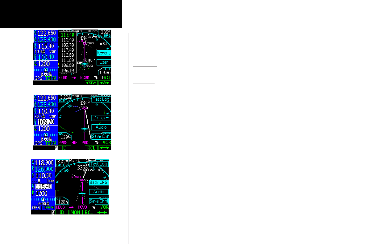
Basic Operation
Nav Radio
VOR - Recall of recent frequencies
Nav Mode ID/To/Fr Selection
Recall (RCL)
1. Press the RCL key to bring up a list of the last eight VOR/ILS frequencies used as the Active frequency.
2. Turn the Large knob to highlight a frequency.
3. Press the <SBY or <A> keys to insert the frequency.
4. Press the VOR key again if no choice is desired.
Flip/Flop
Press the <-> (flip/flop) key to swap the Active and Standby frequencies.
ID/To/Fr
When the Active frequency is a VOR, you can view the current course To/Fr the VOR as well as the Identifier and distance. This value appears between the Active and Standby VOR frequencies and to the right. Press
Menu/Enter and then each press of the ID/To/Fr key will toggle between the display of the ID (Identifier), To
radial, or From radial values.
Back Course
When the Active frequency is an ILS, the Back Course mode will be available for ILS frequencies. Press Menu/
Enter and then the Back CRS key to turn Back Course mode on. Back Course mode reverses needle sensing.
When on, the Back CRS menu label will be highlighted and the BC annunciator will appear. When you are using the backcourse mode in the GNS 480, do not use the back course mode on your autopilot if it has a back
course mode.
Audio
This function operates the same as in Com mode.
User
This function operates the same as in Com mode. The Com and Nav User lists are separate sets of 25.
Save Channel
This function operates the same as in Com mode.
Nav Mode Back Course Selection
50
Page 59

Test Log
The Test Log function allows you to store information about the last time you tested your Nav receiver. The
information you can enter includes: Date (month, day, year), Type of test (Differential, Ground, Air), Location
(text), Bearing Error (-5 to +5), and name of person logging the test information (text).
1. In the Nav function, Press Menu/Enter and then the Test Log key.
2. Press the EDIT key. The month of the Date will be highlighted.
3. Turn the Small knob the change the month of the date. Turn the Large knob to move to Day of the
Date.
4. Turn the Small knob to change the day. Turn the Large knob to move to the year. Turn the Small knob
to change the year.
5. Turn the Large knob to move to the Type selection. Turn the Small knob to choose between
Differential, Ground, or Air. Differential means the value was referenced to another calibrated source
or unit. Ground means the unit was calibrated while on the ground. Air means the unit was calibrated
while in the air.
6. Turn the Large knob to move to the Location selection. Press the Cursor knob in to start editing. Turn
the Small knob to change the character. Turn the Large knob to the next character and turn the Small
knob to change the character. When editing is complete, press the Cursor knob again to exit editing
the Location.
7. Turn the Large knob to move to the Brg Error selection. Turn the Small knob the change the value
required to center the needle. Left for “-” and right for “+” corrections.
8. Turn the Large knob to move to the Name selection. This value if for recording the name of the person
entering the values in the Test Log. Press the Cursor knob in to start editing. Turn the Small knob to
change the character. Turn the Large knob to the next character and turn the Small knob to change
the character. When editing is complete, press the Cursor knob again to exit editing the Name.
Basic Operation
Nav Radio
Nav Mode Test Log Information
51
Page 60

Basic Operation
XPDR
Transponder Control (XPDR)
If a remote compatible transponder is connected and setup to operate with the GNS 480, the Transponder
Control Mode will allow you to control your transponder from the GNS 480 front panel. Some features are
common to the available transponders and are explained below. Press XPDR to activate Transponder mode.
Ident
Press the IDNT key once to activate the Ident mode. The key label will be highlighted and an IDNT annunciator will appear by the squawk code for 20 seconds.
Transponder Mode Smart Keys
Standby
Press the STBY key to place the transponder in Standby mode. No information will be transmitted while in
Standby mode. A SBY annunciator will appear to the left of the squawk code.
ON
Press the ON key to enable Mode A operation. An ON annunciator will appear to the left of the squawk code.
ALT
Press the ALT key to enable Mode C/S operation, which also sends altitude data along with your squawk code.
An ALT annunciator will appear to the left of the squawk code.
Transponder Line Selection Keys
Press the Menu/Enter key to display the keys on the right side of the screen.
Emergency
Press the Emrgncy key to select the emergency 7700 squawk code. This menu item is available when used
with the SL70, SL70R, GTX 32, GTX 327, GTX 33, and GTX 330.
52
Page 61

VFR
Press the VFR key to select the VOR 1200 squawk code. This value can be set in the System Configuration
mode. This menu item is available when used with the SL70, SL70R, GTX 32, GTX 327, GTX 33, and GTX
330.
TrgrSpd
The TrgrSpd key allows you to edit the aircraft speed that will switch the transponder automatically between
active and standby. See the Auto mode description below. This menu item is available with the SL70/SL70R.
Auto
When Auto mode is selected, the transponder will automatically become active after the aircraft reaches the
XPDR Mode - Trigger Speed Setting (SL70 only)
Trigger speed. While the aircraft is below the Trigger speed, your transponder will not send any information.
This menu item is available with the SL70/SL70R.
1. In Transponder mode, press Menu/Enter.
2. If necessary, edit the Trigger Speed. Press TrgrSpd. Select the desired Trigger Speed with the Large
and Small knobs. Press Menu/Enter.
3. Press Menu/Enter. Press the Auto key. Auto mode is active when it is highlighted. Press Auto again
when you want to deactivate the Auto mode.
Flight ID
For GTX33/330 installations, the Flight ID can be either tied to the tail number of the aircraft (set at installation time) or set to another value by the flight crew as needed. The Flight ID key allows you to either just view
the Flight ID or view and edit the Flight ID. For installations that allow editing of the Flight ID, care should be
taken that the Flight ID has no more than 7 characters, is left justified (characters start on the left), and there
are no spaces. This is in accordance with ICAO Doc 8168 [PANS-OPS] Vol. I, Part VIII, 1.3, which states that
flight crew of aircraft equipped with Mode S having an aircraft identification feature shall set the aircraft identification in the transponder. Refer to ICAO Doc 8168 Vol. I, Part VIII, 1.3 for more information.
1. Press Flight ID to allow entry of a Flight ID. This menu item is available with the GTX 33 and GTX 330.
This allows the GTX 33/330 to view and modify the Flight ID.
XPDR Mode - Manual Squawk Code Entry
Basic Operation
XPDR
53
Page 62

Basic Operation
XPDR
Selecting the transponder squawk code.
2. Turn the Small knob to change characters. Turn the Large knob to move to the next character. Press
the CLR key to delete a character.
3. Press the Menu/Enter key to end editing and save the values.
Ground
When the Ground selection is pressed the GTX 33 or 330 will be placed in Ground mode where the transponder operation will operate normally except no Mode A or C replies are allowed. Squitter replies to discretely
addressed Mode S interrogations are allowed. GND will be annunciated to the left of the squawk code on
the GNS 480. GND mode also allows the GTX 33 and 330 to transition to ALT based on the GTX criteria for
ground to airborne determination.
Manually Select a Squawk Code
1. Press the CRSR in or turn the Large knob to activate squawk code editing. Numbers 0 - 7 will be
displayed adjacent to the Smart and Line Selection keys.
2. Press the key for the desired number. After pressing a numbered key, the next number to the right will
be active for editing.
or
1. Change the number value with the Small knob and move to the next number with the Large knob.
2. After selecting the fourth number, turning the Large knob or pressing Menu/Enter key will end
editing.
3. You can press the CRSR knob while editing to cancel any changes.
NOTE: The current squawk code will be replaced by four yellow dashes, if the remote transponder was never established. The last valid squawk code used will be displayed in yellow, if
communication with the transponder is lost while in use.
54
Page 63

Flight Planning (FPL)
The Flight Planning function lets you set up and store flight plans where you can name the flight plan, insert
a series of waypoints, airway segments, departure, arrival, and approach procedures, add comments, save the
plan, and execute it. There are two groupings of flight plans: a Defined Flight Plan group and the Library Flight
Plans. The Defined Flight Plan group shows the Active flight plan followed by the Modified flight plan and
then the Remote flight plans (dual installations only) which are listed below the Library flight plans. Turn the
Large knob to highlight the flight plan to perform the
operation on.
Active Flight Plan
The Active flight plan is the flight plan that the GNS
480 is currently using for navigation guidance. The Active plan stays active until you replace it with another
flight plan or clear it. With the Active plan highlighted,
the menu items are: View, Reverse, Save, or Edit.
If you press the CLR key, you will be prompted to
verify that you want to clear all information out of the
Active plan which is the same as cancelling your flight plan. The Active plan is cleared of all information, but
the Library flight plan of that name is not changed.
Modified Flight Plan
The Modified flight plan is a temporary copy of the Active flight plan that you can edit prior to executing or
saving the changes. The Active plan won’t be affected by the Modified flight plan until you execute it. When
you execute a flight plan, it becomes the Active flight plan. With the Modified plan highlighted, the menu
items are: Execute, Save, or Edit.
Remote Flight Plan
A Remote flight plan is the active flight plan received from another connected GNS 480 when not in Cross
Link (X-Link) mode. The Library flight plans are list of flight plans stored for future use. With the Remote plan
highlighted, the menu items are: View, Execute, or Save.
Basic Operation
Flight Planning
Work flow for modifying a flight plan
55
Page 64

Basic Operation
Flight Planning
List of Flight Plans
Library Flight Plan
The flight plan Library contains up to 50 flight plans you have created and saved. With a Library flight plan
highlighted, the menu items are: Execute, Comment (Cmnt), Copy, or Edit. When you Execute (EXEC) a flight
plan from the Library, you select a flight plan by scrolling through the Library list with the Large knob and
press EXEC. Press Menu/Enter to confirm the action to replace the Active flight plan with a Library flight
plan. A copy of the flight plan is then set as the Active plan that your GNS 480 will use to navigate. The flight
plan in the Library remains separate from the Active flight plan. The Comment (CMNT) menu item allows you
to add a line of text below the flight plan name.
Flight Plan Functions
The function and the menu item smart keys adjust to reflect the appropriate commands for the flight plan or
operation you are viewing.
View
Displays the active flight plan.
Back
Press the BACK function smart key to return to the previous display. No change is made to the page you were
viewing.
Edit
Use this feature to edit an existing flight plan. Editing a displayed flight plan will not change the active flight
plan.
Expand (XPND)
Pressing the XPND key toggles between a simple view of the waypoints in the flight plan and one that shows
the details of the procedures and airways.
Expanding a flight plan for more detail
56
Page 65

Basic Operation
Cross Link (X-Link)
Two GNS 480’s can be connected and set up during installation to work together. Flight plans and User
waypoints are shared. Pressing the SUSP key on either unit will suspend waypoint sequencing on both units.
When the X-Link function is activated, the units will share control of the active flight plan. Pressing the X-
Link menu key activates the Cross Link function. The X-Link menu item will be highlighted when X-Link is
active. Both units will then show “Active Linked” on the top line of the Flight Plan page. Any changes made to
the active plan on any unit will be sent to the other unit. Pressing the X-Link menu key again will deactivate
the Cross Link function and the term “Linked” will be removed from the active flight plan name.
Flight Planning
Remote Flight Plans
When the Cross Link function is not activated, changes to the active flight plan will be sent to the other unit
for viewing only and noted as “Remote.” The Remote flight plans exist as part of the library of flight plans
shared by the two units. The units do not share the Active flight plan used for navigating unless Cross Link
(X-Link) is activated.
When the units are powered on, they synchronize their flight plans and User waypoints. The unit with the
most recent flight plans and User waypoints will take precedence and replace the plans and User waypoints in
the other unit. To avoid confusion and loss of flight plan information, power both units on at the same time
and keep both units on when they are used.
Reverse (Rvrse)
Pressing the Rvrse key will create a Modified flight plan that is a copy of the active flight plan and reverse the
waypoints. Any procedures or approaches will be removed from the Modified flight plan.
Save
Press the Save key to save the active flight plan to memory. If a flight plan exists with the same name, the GNS
480 will create a comment and attach it to the flight plan to show the difference. Press Menu/Enter for Yes or
CLR for No.
Flight Plan with X-Link Active
Remote Shared Flight Plan
Modified Flight Plan
57
Page 66

Basic Operation
Flight Planning
Select an Origin Waypoint for Flight Plan
Edit
Pressing the Edit menu item key, while highlighting the Active flight plan, creates a copy of the active flight
plan, which is called the “Modified” flight plan. Making a copy protects you from accidently changing your active flight plan. You can now edit the “Modified” flight plan. If you are already viewing a “Modified” flight plan,
you will be prompted to replace the current modified flight plan (Menu/Enter) or keep the current one (CLR).
1. Turn the Large knob to move to the leg to modify (highlighted in green).
2. Press Modify to change the selected leg or procedure. Use the Large and Small knobs to select a new
waypoint and press Menu/Enter.
3. Press the →Wpt key to insert another Waypoint or press the Arwy key to insert an Airway.
4. After modifying the flight plan, the smart keys give you the choice of Back, Executing, or Expanding and
viewing details in the new Flight Plan
Execute (Exec)
Use the Execute command to make the highlighted flight plan the Active flight plan. A flight plan that is being
modified will not be used until you press Exec and confirm the activation.
Comment (Cmnt)
This function allows you to place a comment, of up to one line of text, for the flight plan. The comment will be
placed just below the flight plan name.
Copy
The Copy function creates a duplicate of the selected flight plan. You can use the Copy function as a timesaving method to create a new flight plan when you will reuse many of the same waypoints and procedures.
Removing a discontinuity from a Flight Plan
58
Page 67

Discontinuity
A Discontinuity is a message placed in the affected position in a flight plan indicating the GNS 480 needs to
know how you want to go between the two waypoints. Discontinuities are also inserted into the flight plan
when a standard instrument departure (SID) does not match the first waypoint in the en route section of the
flight plan or when STAR or approach end points do not match or when a STAR terminating waypoint does
not match the IAF of the approach.
Close the gap between waypoints by inserting waypoints or airways, or remove the discontinuity. You may
delete the Discontinuity by turning the Large knob to highlight it and then pressing the CLR key. Deleting a
discontinuity results in a direct path between those waypoints.
When the discontinuity is caused by an aspect of the flight plan, such as an approach, the needed action may
not be known before the flight begins. It is not necessary to remove the discontinuity, immediately. At some
point in the flight, the pilot needs to fill in the information needed to complete the flight plan and remove the
discontinuity. If the discontinuity is not removed, “disco” will be displayed on the bottom of the map display
for the next and then the active legs as a reminder to correct the flight plan. If you fly into a discontinuity, the
flight plan will be suspended and the GNS 480 will continue to track outbound on the same course until you
take action.
Pilot Nav Legs
When the “Pilot Nav” message appears on a leg in your flight plan it means the GNS 480 will not provide guidance on that leg. You will have to use other flight instruments or autopilot modes to fly the given procedure leg.
The GNS 480 will go into Suspend mode when the current leg is a Pilot Nav leg. Pressing SUSP again
sequences you to the next leg in the procedure. If the next leg is a course-based leg, the course deviation
indicator will begin to center on intercept. You may engage the appropriate NAV mode on your autopilot or
flight director.
Setting up IFR Flight Plan waypoints
Basic Operation
Flight Planning
59
Page 68

Basic Operation
Flight Planning
Searching for Waypoints to Insert into a Flight Plan
The following steps describe in general how you can select a waypoint for one of the points in a flight plan.
1. Press the FN key (if necessary) and then the FPL key.
2. Press the NEW key. The waypoint database will be displayed. You can choose to search for a waypoint
by the Identifier, Facility Name, Location, or Waypoint Type. The nearest airport within 30 NM will be the
default waypoint.
3. Select by Identifier
a. With the first character of the Identifier highlighted, turn the Small knob to select the desired
character.
b. Turn the Large knob clockwise (CW) to the next character and select the character by turning the
Small knob.
4. Select by Waypoint Type
a. With the first character of the Identifier highlighted, press the CRSR knob in. The whole Identifier
field will be highlighted. Now turn the Large knob counter-clockwise (CCW) one turn to highlight the
waypoint type field.
b. Turn the Small knob to display the different waypoint types.
5. Select by Facility Name
a. With the first character of the Identifier highlighted, press the CRSR knob in. The whole Identifier
field will be highlighted. Now turn the Large knob CCW one turn to highlight the Facility Name field.
b. Turn the Small knob to display the facilities in alphabetic sequence.
6. Select by Location
a. With the first character of the Identifier highlighted, press the CRSR knob in. The whole Identifier
field will be highlighted. Now turn the Large knob CCW one turn to highlight the Location field.
b. Turn the Small knob to display the facilities in alphabetic sequence.
60
Page 69

Activate a Flight Plan
1. Press the FPL function smart key to display the Flight Plan library. If the active flight plan is displayed,
press the BACK function smart key.
2. Turn the Large knob to the desired active flight plan.
3. Press the EXEC function smart key.
Delete the Active Flight Plan
1. Press the FPL function smart key to display the Flight Plan library.
2. Turn the Large knob if necessary to highlight the active flight plan.
3. Press the CLR key.
Edit a Flight Plan
Changing Origin, Destination, & Alternate Waypoints
1 Press FN and then the FPL function smart key.
2. Turn the Large knob to highlight the flight plan to edit and press the EDIT function smart key.
3. Turn the Large knob to highlight the flight plan name.
4. Press the Origin or Dest or Alternate menu item smart keys to change these waypoints.
5. The flight plan is renamed and shown in the Library by the new Origin and Destination waypoint names.
6. Press the SAVE function smart key to save the flight plan.
Inserting a Waypoint or Airway in Your Flight Plan
1. Highlight a waypoint with the Large knob.
2. Press the ->Wpt menu item smart key to insert another waypoint.
3. Use the Large and Small knobs to select a waypoint and then press Menu/Enter. The new waypoint
will be inserted after the highlighted waypoint or en route intersection.
4. If the waypoint is on an airway (such as a VOR), Airways will be available to insert into your flight plan.
Press the ->Arwy menu item smart key. Use the Large and Small knobs (or smart keys) to select the
Airway and exit waypoints. Press Menu/Enter.
5. Press the XPND function smart key to expanded view all of the waypoints inserted automatically by
inserting the airway.
Basic Operation
Flight Planning
61
Page 70

Basic Operation
Flight Planning
Deleting a Waypoint or Airway in Your Flight Plan
1. While editing your flight plan, turn the Large knob to highlight the waypoint or airway, in the
compressed view (XPND is not highlighted), you want to delete.
2. You can edit in the expanded or compressed view of your flight plan. In the expanded view, you can
select each individual leg of your plan. In the compressed view, you can select and remove waypoints or
airways that will also include associated part of that waypoint or airway.
3. Press the CLR key to remove a waypoint or airway. Deleting an airway generates a message you must
acknowledge.
4. Press the SAVE function smart key to save your changes and return to the flight plan library.
Steps for Setting Up a Simple Flight Plan
1. Press the FN key (if necessary) and then the FPL key.
2. Press the NEW key. The waypoint database will be displayed. You can choose to search for a waypoint
by the identifier, facility name, city, or waypoint type.
3. Select the Origin waypoint as described in “Edit a Flight Plan” above. Press Menu/Enter.
4. Select the Destination waypoint. Press Menu/Enter.
5. Select the final operation for creating this flight plan: Save or Execute. Press SAVE to store the flight
plan in the Library for future use or press EXEC to both save the Library plan and make the plan the
Active flight plan.
Steps for Setting Up a Flight Plan Using Terminal Procedures and Airways
Procedures can be inserted at the time you are creating the flight plan (as described here) or later with the
Procedure (PROC) function. The general phases of flight are shown below with the details following.
NOTE: If the datum for an airport is unknown, terminal and/or instrument procedures will
be available, however navigating with them will cause a reminder message, “Non WGS-84
waypoint navigation.” The procedures are present, but must be selected from multiple transitions. Note that the name may not match the paper approach. Verify the sequence of waypoints
to ensure you have selected the desired procedure.
62
Page 71

Take off
A. Set Origin, Destination, and Alternate Waypoints.
B. Add Standard Instrument Departure Procedure (SID), if required.
C. Insert en route flight plan of Airways and/or Waypoints.
En Route
D. Modifying a Flight Plan While in Flight
Approach and Landing
E. Add Arrival Procedures (STAR).
F. Add Approach Procedures when you receive clearance.
A. Set Origin, Destination, and Alternate Waypoints
1. In Flight Plan mode, press the NEW key.
2. Use the Large and Small knobs to select the Origin waypoint. Press Menu/Enter.
3. The Destination waypoint selection page will now be displayed. Select the Destination waypoint and
press Menu/Enter.
4. Set an Alternate airport, if desired. Turn the Large knob CCW to highlight the flight plan name. Press
the Altrnt key and select an alternate airport/waypoint along the flight plan with the Large and Small
knobs. The alternate airport will be added in parentheses to the flight plan name.
5. Press SAVE.
B. Add a Standard Instrument Departure (SID) Procedure
SIDs may be modified in either the Flight Plan (FPL) or Procedure (PROC) modes. The Procedure mode
method is shown.
1. In Flight Plan mode, highlight the flight plan name and press EXEC.
2. Press FN and then PROC.
3. In the Origin section press the Depart key.
Basic Operation
Flight Planning
NOTE: Guidance is not provided for Pilot Nav legs or Vectored SIDs. (Not in the database)
63
Page 72

Basic Operation
Flight Planning
64
4. The runway is highlighted. Use the Small knob or menu item keys on the right side of the display to
select a runway.
5. Turn the Large knob to select the departure procedure and transition.
6. Verify your flight plan and resolve any discontinuities. Press Menu/Enter to insert the procedure into
your modified flight plan.
C. Insert En Route Flight Plan Airways and/or Waypoints
1. While in Edit mode, turn the Large knob CW to highlight the waypoint where you want to insert a waypoint
or Airway in your flight plan after it. Press →Wpt or →Arwy. In this example, Airway is selected.
2. Turn the Small knob or press one of the Menu Item keys next to the available airways to select the
airway.
3. Turn the Large knob CW one position to highlight the Intersection choices. Turn the Small knob to
choose the desired waypoint to exit the Airway. Press Menu/Enter.
D. Modifying a Flight Plan While In Flight
Flight plans may be modified in either the Flight Plan (FPL) or Procedure (PROC) modes. In Flight Plan mode
you can modify the entire flight plan. In Procedure mode you can modify procedures for the Origin and Destination airports. Both methods are shown below.
Using Flight Plan Mode to Modify a Flight Plan
1. Press the FN key and then the FPL key.
2. If necessary, highlight the Active flight plan. Press the EDIT key.
3. If you want to change the Origin, Destination, or Alternate airports, press the appropriate selection key
on the left side of the display when the flight plan name is highlighted. If you want to insert a waypoint
or airway, go to step 5.
4. Turn the Large knob to highlight the leg where you want to make the change.
5. Press →Wpt to insert a waypoint or →Arwy to insert an airway following the highlighted leg. If the
airway choice is not available there are no airways available for that waypoint. Delete a waypoint or
airway by pressing the CLR key.
6. Press XPND to display all of the legs of the flight plan.
7. Review your flight plan to resolve any discontinuities as desired and then press the EXEC key to
execute.
Page 73

Selecting an Alternate Airport
1. Press FN and then PROC to go to the Procedure Mode.
2. Press the Select key next to the Alternate airport.
3. Next, press the Load key to load the alternate to the destination airport into your flight plan. \
4. If you want to choose a different Alternate airport, press Modify, choose another airport with the
Large and Small knobs and press Menu/Enter. If you do not have an Alternate airport, select one by
pressing Modify and select one with the Large and Small knobs followed by pressing Menu/Enter.
5. Insert any waypoints, or airways, for the diversion and then press EXEC.
NOTE: When you execute the changed plan, you will not have an active leg until you activate
a new flight plan leg with either the FlyLeg, Direct-To, or CrsTo functions.
For an alternate nearby airport, use the NRST function and fly Direct-To a new DEST (destination).
E. Add Arrival Procedures (STARS)
1. Press the Arrival key in the Destination section.
2. Use the Large and Small knobs to select the runway, arrival, and transition.
3. Press Menu/Enter.
F. Add Approach Procedures
1. Press the Appr key. Select the approach with the Large and Small knobs, or the keys on the right side
of the display. Press Menu/Enter.
2. Press the XPND (Expand) key to view all waypoints and legs in the flight plan. Every waypoint, airway,
procedure, and intersection is shown with the bearing and distance of each leg. Verify the waypoints in
your flight plan and resolve any discontinuities.
3. Press EXEC.
Basic Operation
Flight Planning
Flying Direct to a Waypoint in a
Flight Plan
1. Press Direct-To. The flight plan waypoint
list will be displayed.
2. Turn the Large knob to highlight the
desired waypoint.
3. Press the Direct key on the right side of
the display.
Making a Flight Plan Leg Active
With the FlyLeg Menu selection, you can
activate a particular leg of your flight plan.
This feature allows you to bypass a waypoint
in your flight plan.
1. Press Direct-To.
2. Select the desired leg of your flight plan
with the Large knob (ActFP smart key is
highlighted).
3. Press the FlyLeg key to activate the
selected leg.
65
Page 74

Basic Operation
Flight Planning
LEG TYPES
The GNS 480 is the only panel mount navigator to implement all the available leg types that currently exist in airways, instrument procedures, and approaches. These legs are described in the following diagrams, with associated descriptions of each leg. Because the GNS 480
supports these leg types, it automatically sequences through the majority of the flight plan legs, or allows for a simple one keystroke interface
to sequence when automatic sequencing is not available. This greatly reduces the pilot’s workload during critical phases of flight, such as
departure or approach and landing.
An example of how these leg types are implemented can be found in a simple SID procedure, such as the Farmington Three Departure at
KHIO. If we depart on Runway 30, the text of the departure on the Jeppesen plate is as follows: Turn LEFT to a 120° heading, then intercept
and proceed via UBG R-346 to UBG VOR. Thence via assigned route.
To dissect this example, look on the flight plan page after inserting the departure and see the legs the GNS 480 automatically inserts, the first
being a heading of 305° to an altitude of 604 feet MSL. This is because no turns are allowed below 400 feet AGL for an instrument departure.
Upon reaching the required altitude, the GNS 480 will sequence automatically to a heading to intercept leg of 120° to the 166° course to
UBG. The heading leg of 120° is shown as a Pilot Nav leg and sequencing may be accomplished by pressing the SUSP key once. Once the
flight plan sequences, the guidance to the 166° course will be active on your CDI to complete the intercept. Roll steering is active and you
may engage the NAV mode or roll steering mode as appropriate. After reaching UBG, the system will automatically sequence to the next leg
in your en route flight plan. Roll steering or course guidance is not available on heading legs.
NOTE: If the GNS 480 does not have an altitude input, the system will not sequence automatically on the missed approach. It is advisable to install
the GNS 480 system with an altitude input.
Turn Short Path Calculation
The GNS 480 will automatically calculate a turn short curved path as it sequences between waypoints, when allowed. The size of the
turn short curved path radius is calculated based upon aircraft ground speed. This is shown in magenta on the moving map adjacent
to the active waypoint and leading to the course to the next waypoint. The GNS 480 roll steering autopilot commands will follow the
magenta curved path. A turn short is not calculated for course changes in excess of 120°.
66
Page 75
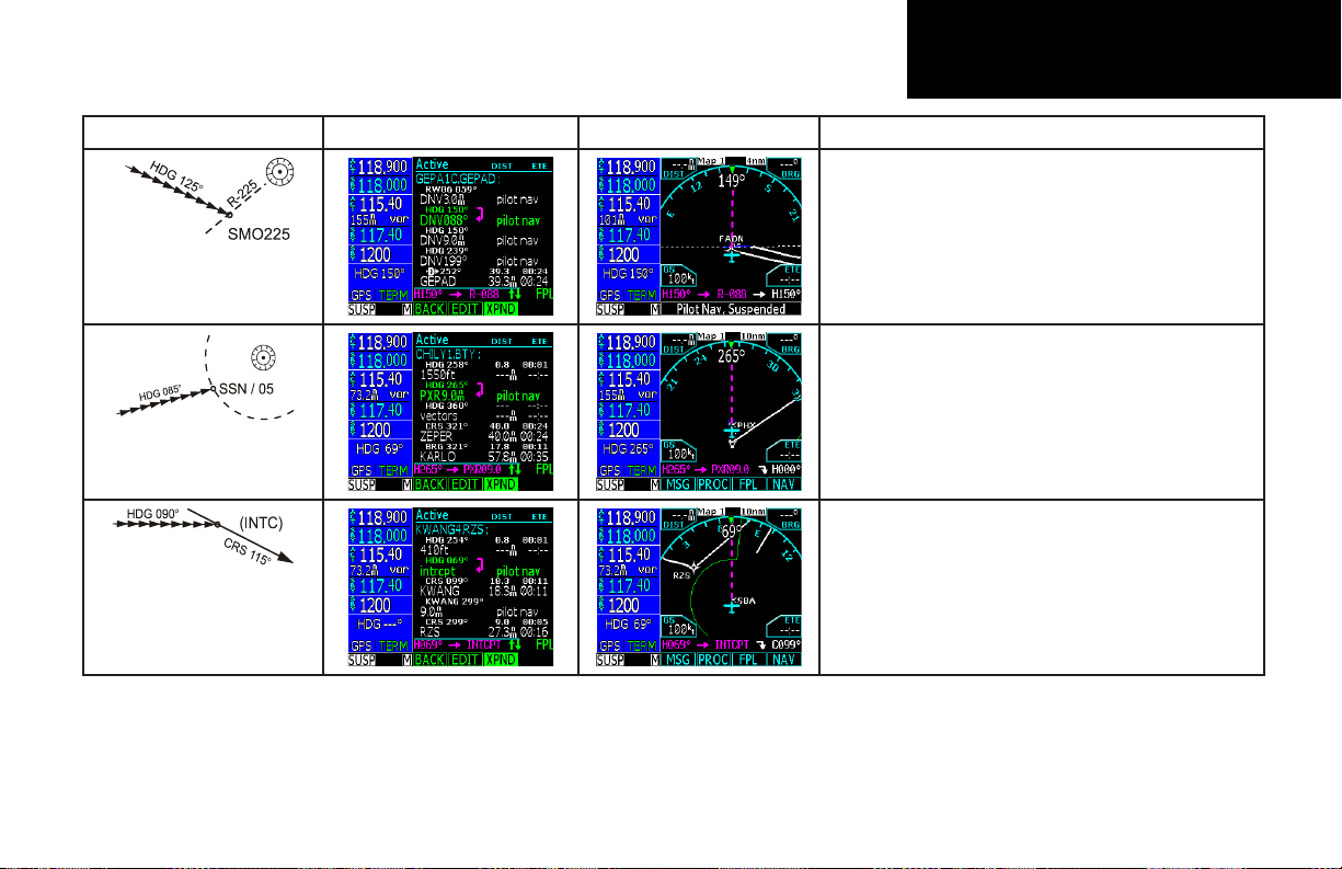
Leg Types Flight Plan Page Active From/To/Next Waypoints Description
(PILOT NAV) The heading to a radial leg defines a heading
to fly and a VOR radial at which the leg terminates. The VOR
radial is defined by both the VOR identifier and the radial
number. The pilot will have to maintain the desired heading
manually and initiate sequencing manually upon approaching
the specified radial. This can be easily accomplished using the
VOR receiver.
Heading to a VOR Radial
(PILOT NAV) The heading to a DME distance leg defines a
heading to fly and a DME distance at which the leg terminates.
The distance is defined by both the identifier of the DME fix
and the distance. The pilot will have to maintain the desired
heading manually and initiate sequencing manually upon
reaching the specified DME distance.
Heading to a DME Distance
(PILOT NAV) The heading to an intercept leg defines a heading
to intercept the next leg. The pilot will have to maintain the desired heading manually and initiate sequencing manually upon
intercepting the next leg of the flight plan. The next course will
be shown on the moving map.
Heading to Intercept
Basic Operation
Flight Planning
67
Page 76

Basic Operation
Flight Planning
Leg Types Flight Plan Page Active From/To/Next Waypoints Description
Heading to a Manual Termination
(Vector)
Heading to an Altitude
Course to a Fix
The heading to a manual termination leg defines a heading to
fly until the pilot initiates sequencing. Like the fix to a manual
termination leg, this type of leg is most often used where the
pilot is to expect vectors from air traffic control. The pilot will
have to maintain the desired heading manually and initiate
sequencing manually when appropriate.
The heading to an altitude leg defines a heading to fly and
an altitude at which the leg sequences. The pilot will have to
maintain the desired heading manually, but sequencing to the
next leg in the flight plan happens automatically upon reaching
the specified altitude.
The course to a fix leg defines a path to a fix on a specific
course. When a course to a fix leg is used for a vectors-to-final
approach transition, the course is preceded by the word “vectors” in the flight plan view.
68
Page 77

Leg Types Flight Plan Page Active From/To/Next Waypoints Description
The course to an altitude leg defines a specific course to be
flown from the position at which the leg is initiated and an
altitude at which the leg terminates. Sequencing occurs automatically upon reaching the specified altitude.
Course to an Altitude
(PILOT NAV) The course to a DME distance leg defines a
specific course to be flown from the position at which the leg is
initiated and a DME distance at which the leg terminates. The
distance is defined by both the identifier of the DME fix and
the distance, as shown in the example the Course-To is C238
and the Identifier is VIL with the DME distance of 0.70 nm is
shown in brackets. The pilot will have to maintain the desired
Course to a DME Distance
Course to Intercept
course manually and initiate sequencing manually upon reaching the specified DME distance.
(PILOT NAV) The course to an intercept leg defines a specific
course to be flown from the position at which the leg is initiated. It terminates upon intercepting the next leg. The pilot
will have to maintain the desired course manually and initiate
sequencing manually upon intercepting the next leg of the
flight plan.
Basic Operation
Flight Planning
69
Page 78

Basic Operation
Flight Planning
Leg Types Flight Plan Page Active From/To/Next Waypoints Description
(PILOT NAV) The course to a radial leg defines a specific
course to be flown from the position at which the leg is initiated and a VOR radial at which the leg terminates. The VOR
radial is defined by both the VOR identifier and the radial
number. The pilot will have to maintain the desired course
manually and initiate sequencing manually upon approaching
Course to a VOR Radial
Constant Radius Arc
Track to a Fix
the specified radial. This can be easily accomplished using the
VOR receiver.
The constant radius arc leg is similar to an arc to a fix leg. This
leg can occur at any location and will define an arced path
between two other legs. Also, unlike the arc to a fix leg, there
should be no separate turn required at the beginning or end of
this type of leg. You may fly this leg keeping the CDI centered
as you fly the curved path.
The track to a fix leg is the most commonly used leg type for
GPS navigation. It defines a geodesic (or great circle) path from
the previous database fix to the next database fix.
70
Page 79

Basic Operation
Flight Planning
Leg Types Flight Plan Page Active From/To/Next Waypoints Description
The initial fix defines a database fix to be used in the flight
plan, not an actual leg. The fix will serve to define the beginning of a leg that follows such as a track to fix or course from
fix leg. .
Initial Fix
The procedure turn leg defines a course reversal procedure
starting at a database fix, with a specific course, and a direction, left or right, to initiate the turn. A maximum distance
in which the turn must be accomplished is also defined and
drawn on the moving map. This type of leg is always followed
by a course to a fix leg that establishes the inbound course after
Procedure Turn
Direct to a Fix
the turn is completed.
The direct to a fix leg allows navigation directly to a database
fix from your present position. When direct to navigation is
initiated by the user, the GNS 480 will create a curved path
that aligns the aircraft on a direct course to the fix. Direct to fix
legs are also used in some procedures.
71
Page 80

Basic Operation
Flight Planning
Leg Types Flight Plan Page Active From/To/Next Waypoints Description
The hold to a fix leg defines a holding pattern that is to be
flown only once. This leg is most often used in newer RNAV
procedures in place of a procedure turn to accomplish a course
reversal.
Hold to a Fix
The hold to an altitude leg defines a holding pattern to be
flown and an altitude at which the holding pattern is to be
terminated. This leg is most often used in a departure where a
certain altitude must be attained in a hold before continuing
en route.
Hold to an Altitude
The hold to a manual termination leg defines a holding pattern
to be flown for an indefinite number of turns. These can be
added using the Hold function under the Direct-To key. They
almost always are the termination of a published missed approach.
Hold from a Fix to a
Manual Termination
72
Page 81

Leg Types Flight Plan Page Active From/To/Next Waypoints Description
Course from a Fix to an Altitude
Track from a Fix to a Distance
Fix to a DME Distance
Basic Operation
Flight Planning
(PILOT NAV) The fix to an altitude leg defines a specific course
to be flown away from a database fix and an altitude at which
the leg terminates. The pilot will have to maintain the desired
course manually and initiate sequencing manually upon reaching the specified altitude.
(PILOT NAV) The fix from a distance leg defines a specific
course to be flown away from a database fix and a distance
from the fix at which the leg terminates. The pilot will have to
maintain the desired course manually and initiate sequencing
manually upon reaching the specified distance from the fix.
(PILOT NAV) The fix to a DME distance leg defines a specific
course to be flown away from a database fix and a DME
distance at which the leg terminates. Since the leg does not
necessarily start at the DME, the distance is defined by both the
identifier of the DME fix and the distance. The pilot will have
to maintain the desired course manually and initiate sequencing manually upon reaching the specified DME distance.
73
Page 82

Basic Operation
Flight Planning
Leg Types Flight Plan Page Active From/To/Next Waypoints Description
The fix to a manual termination leg defines a specific course to
be flown away from a database fix to an unspecified location.
This type of leg is most often used where the pilot is to expect
vectors from air traffic control, for example, at the end of an arrival. The pilot will have to initiate sequencing manually when
appropriate. If this fix to manual termination leg was initiated
Course from a Fix to a
Manual Termination
DME Arc
by the pilot using the course-from function under the Direct-To
key, then sequencing will not be allowed.
The arc to a fix leg is used to define a DME arc leg. A DME
distance and the terminating fix are used to define this leg. This
leg is typically used in VOR-DME approaches. The GNS 480
provides guidance on curved path DME arcs. The pilot can
maintain the arc by keeping the CDI centered manually or by
using the autopilot.
74
Page 83

Procedures
The Procedure mode allows you to add or modify procedures to standard locations within the active flight
plan. No options will be available if there is not an active flight plan. When you start adding or modifying
procedures, a modified (copy of the active) flight plan is created. You can only change the Origin approach
and departure procedures, Destination arrival and approach procedures, and select an alternate airport. At the
bottom of the screen, the flight plan status of either Active or Modified will be shown.
Selecting Procedures
1. Press FN and then the PROC function smart key.
2. Press the Appch (Approach), Depart (Departure), or Arrival menu item smart keys for the Origin or
Destination (Dest) waypoints.
3. For approaches, a list of procedure types is shown on the right side of the screen. Pressing the menu
item key next to the procedure type (GPS, ILS, LOC, VOR, or NDB) will make those types available on the
top line of the screen.
4. Use the Large knob to move between fields and the Small knob to scroll through the available
procedure choices. A representative map is shown below the procedure name.
5. You can press the BACK function smart key to back up to the main Procedure page without making
any changes.
6. Press Menu/Enter to select the procedure. This inserts it into the Modified Flight Plan and proceeding to
Flight Plan Edit mode for review and execution.
Basic Operation
Procedures
Activating an Approach
After selecting the procedures for your flight plan, press the EXEC function smart key to activate the modified flight plan with the added procedures. When you press the EXEC key, you will be prompted to press the
Menu/Enter key to replace the Active flight plan with the Modified flight plan. Pressing BACK takes you back
to the Procedures page without activating the modified plan. Pressing the VTF (Vector To Final) key creates
and activates a leg in the flight plan that is an extension of the Final Approach Course beyond the FAF.
NOTE: VTF can be selected regardless of the initial approach fix
selected. If ATC vectors you after
selecting an expected transition,
VTF will remove the transition and
extend the final approach course
automatically.
75
Page 84

Basic Operation
Procedures
Steps for approach operations
• Editmode
• Modifyightplan
• Reviewightplanmodications
against published charts
• Executetheightplan
Basic Approach Operations Examples
The GNS 480 provides precision and non-precision approach guidance using its built-in GPS receiver. The
moving map pages can also be used as a supplemental aid to situational awareness for ILS approaches (and
non-precision localizer-based approaches), but the localizer and glideslope receivers MUST be used for primary
approach course guidance. The GNS 480 also provides GPS precision approach capability, known as LPV approaches.
Approaches designed specifically for GPS are often very simple and don’t require overflying a VOR or NDB.
Currently, many non-precision approaches have “GPS overlays” to let you fly an existing procedure (VOR,
VOR/DME, NDB, RNAV, etc.) more accurately using GPS. To date, there are over 2,400 GPS-only approaches
and over 2,900 GPS overlay approaches worldwide.
Many overlay approaches are more complex (in comparison to GPS-only approaches). The GNS 480 displays
and guides you through each leg of the approach — automatically sequencing through each of these legs, up
to the missed approach point (MAP). Approaches may be flown “as published” with the full transition — using
any published feeder route or initial approach fix (IAF) — or may be flown with a vectors-to-final transition.
Approach operations on the GNS 480 typically begin with the same basic steps:
1. Select the destination airport using the Direct-To key (and DEST function), use an existing flight plan,
or use the Procedure Mode.
2. “Load” the approach (often while en route) in anticipation of its future use. This places the approach in
the “modified” flight plan, but retains course guidance from the active flight plan until the approach is
“Executed.”
3. “Execute” the full approach and vectors-to-final, if appropriate. In some scenarios, you may find it
more convenient to immediately execute the approach and fly direct to the Initial Approach Fix (IAF), if
cleared to do so. Verify the flight plan changes prior to executing the active flight plan.
NOTE: If you load an approach with a transition with a procedure turn and then subsequently
are vectored, selection of Vector To Final (VTF) mode removes the procedure turn and extends
the final approach course from the FAF.
76
Page 85

Approaches with Procedure Turns
[RW04]
The procedure turn portion of an approach is stored
as one of the legs of the approach. For this reason,
the GNS 480 requires no special operations from the
Lynchburg (VA) Regional
VOR or GPS Rwy 04
pilot — other than flying the procedure turn itself
— beyond what is required for any other type of approach. The procedure turn is automatically inserted
based on the approach transition selection.
This example uses the VOR Runway 04 approach
for Lynchburg (Virginia) Regional Airport, KLYH,
and assumes a departure from Frederick (Maryland)
Municipal Airport, KFDK direct to KLYH or via an
airway. The steps required to set up and fly the approach are detailed below:
1. While en route to KLYH, some 40-50 nautical
miles away, you select the ATIS frequency to
monitor airport conditions and runway usage.
This is accomplished by displaying the INFO
Page and selecting the ATIS frequency from
the list. Press <-SBY to place the frequency
on standby. Use the COM monitor function to
listen to the ATIS frequency. Your active frequency will not be affected.
2. From ATIS you learn that runway 04 is in use and plan your approach accordingly. Press the PROC key
and select the “VOR 04” approach. From the transitions field, select LYH VOR (the IAF). Press Menu/
Enter to load the approach into the modified flight plan.
3. After you review the modified flight plan, execute it. If you are cleared direct to the IAF, you may
highlight the IAF on the Direct page and select Direct.
DO NOT USE FOR
NAVIGATION
Basic Operation
Procedures
NOTE: Course change messages appear 10 seconds before reaching the change location.
77
Page 86

RW04
Basic Operation
Procedures
Flying the Procedure Turn
1. Within 30 nautical miles of the destination airport, the GNS 480
switches from “en route” mode to “terminal” mode (as indicated
in the lower left corner of the screen). The switch to terminal mode
DO NOT
USE FOR
NAVIGATION
6. After approximately one minute, the GNS 480 will provide a message “RIGHT TO TRK 340°,” the CDI
needle swings to the opposite side to provide proper sensing along the final course segment and
“RIGHT TO TRK 025°” appears on the bottom of the screen when the final approach course becomes
the active leg.
NOTE: For roll steering-capable autopilots, the final approach course may be set at the IAF. The
GNS 480 will fly the entire procedure automatically.
7. As the CDI needle starts to center, make a right turn to 025° — the final approach course.
is accompanied by a gradual Course Deviation Indicator (CDI) scale
transition from 2.0 to 1.0 nautical miles, full scale deflection.
2. For non-roll steering autopilots or manual flight, as you approach
the IAF (LYH), a waypoint message appears in the bottom of the
screen. As the distance (DIST) to the IAF approaches zero, the
message is replaced by a turn advisory (“Left/Right TO TRK 209°”).
Dial the outbound course of 205° into the CDI (or HSI) using the
OBS knob and initiate a standard rate turn to this course heading.
3. Fly the outbound course, keeping the CDI needle centered.
4. Once you have flown approximately one minute past the IAF
(LYH), the message “LEFT TO TRK 164°” appears on the bottom of
the screen. You may initiate the procedure turn at any time after
receiving this alert message.
5. Turn left to a heading of 160° to initiate the procedure turn.
Course guidance is provided relative to the outbound leg from the
FAF. The procedure turn is displayed on the Map Page and indicated
as the active leg on the Default NAV and Active Flight Plan pages.
The CDI needle starts moving to the right.
78
Page 87

8. Within 2.0 nautical miles of the FAF (LYH), the GNS 480 switches
RW04
from terminal mode to “approach” mode. CDI scaling is tightened
from either 2° or 1.0 to 0.3 nautical miles, full scale deflection,
whichever is smaller.
9. As you approach the FAF, a waypoint message on the bottom
of the display “RIGHT TO TRK 025°” appears. Make any course
adjustments necessary for the final course segment (FAF to MAP).
10. As you cross the FAF, the destination sequences to the MAP
(“RW04”), the runway threshold). With the needle centered, fly
toward the MAP, observing the altitude minimums dictated by the
approach plate.
11. As you cross the MAP, you will receive an audio message “missed
approach point” unless there is activity on the active Com
frequency.
Basic Operation
Procedures
DO NOT
USE FOR
NAVIGATION
79
Page 88

RW04
Basic Operation
Procedures
NOTE: Remember that heading legs must be flown manually or by using Heading mode
on your autopilot. If you have a “Pilot Nav” leg in the approach, the GNS 480 will suspend
waypoint sequencing. Press the SUSP key once to sequence to the next leg.
1. Follow the missed approach procedures, as published on your approach plate and for proper climb. The
GNS 480 guides you to the holding pattern, along the 053° radial from LYH VOR. The leg for the 010°
heading will sequence automatically after reaching the appropriate altitude. The heading leg for the
080° heading will suspend. Establish the airplane on a 080° heading, as required. Once established,
press the SUSP key once to cause the GNS 480 to sequence to the next leg. When the 053° course
comes alive, complete the intercept manually, or automatically using the autopilot.
2. A message on the bottom of the screen recommends entry procedures for the holding pattern (i.e.,
“HOLD DIRECT”, “HOLD PARALLEL”, or “HOLD TEARDROP”). As you fly the holding pattern, you may
manually fly the dashed magenta holding pattern on the moving map. The hold is automatically sized
for a one minute leg. Roll steering-capable autopilots will fly the hold and hold entry automatically.
3. The GNS 480 provides course guidance only on the inbound course to the holding fix. When leaving the
holding pattern to re-fly the approach (or another approach) press the PROC key to activate Vector To Final
(VTF) mode for vectors or for a full procedure direct to LYH using the Direct-To key as described earlier.
NOTE: In the event that you wish to divert direct to another destination airport, use the Destination (DEST) function on the Direct-To page.
80
DO NOT USE FOR
NAVIGATION
Flying the Missed Approach
After you pass the MAP, if you cannot continue the
approach and land, usually you must execute a missed
approach. The GNS 480 will automatically sequence
to the first leg of the missed approach. Fly the heading
legs manually. When the heading to intercept course
leg becomes active (080° heading), press the SUSP
key to “unsuspend” waypoint sequencing. You may
reengage roll steering on your autopilot, when the
course comes alive. The GNS 480 will then fly the
Hold Entry and Holding automatically. Non-roll steering autopilots or manual flight may be accomplished
by flying to the CDI. Refer to the Holding section.
Page 89

Flying an Approach with a Hold
Starting where the previous example left off,
we’ll assume weather conditions resulted in
a missed approach at Lynchburg Regional.
Now, you’ve decided to divert to Farmville
Regional (KFVX) instead. If KFVX is nearby,
press the NRST key and use the Large knob
to highlight KFVX.
1. Press the Direct-To key.
2. Press the DEST menu item key. .
3. Press Menu/Enter to confirm.
This time, you select the GPS runway 21
approach into Farmville Regional. The GPS
runway 21 approach begins with a holding
pattern at the IAF, BODRY intersection.
4. Press PROC and select the “GPS 21”
approach.
5. From the transitions window, select the BODRY intersection as the IAF. Review the loaded approach and
select “Execute (EXEC)” to activate the approach. When cleared, select Direct-To BODRY.
6. As in the last example, within 30 nautical miles of the airport, the GNS 480 switches from en route
mode to terminal mode, and the CDI scale transitions from 2.0 to 1.0 nautical miles, full scale
deflection.
Farmville (VA) Regional
GPS Rwy 21
DO NOT USE FOR
NAVIGATION
Basic Operation
Procedures
NOTE: For transitions requiring a course reversal, the GNS 480 will fly the course reversal
automatically. For transitions marked “NoPT,” the GNS 480 will sequence to the next leg to the
DEPOY intersection.
81
Page 90

Basic Operation
Procedures
7. Just prior to crossing the BODRY
DO NOT USE FOR
intersection, a message — ”HOLD
TEARDROP” — appears on the
bottom of the screen to suggest the
proper holding pattern entry. “HOLD
DIRECT AHEAD” or “HOLD TEARDROP
AHEAD” may be offered on other similar
approaches.
8. As mentioned in the missed approach
example, the holding pattern will be
sized correctly for your ground speed
and a one minute leg. If air data is
available to the GNS 480, the hold will
be reshaped to create standard rate
turns at both ends.
NAVIGATION
NOTE: If you need to lose extra altitude or speed by going around the holding pattern again,
press SUSP to manually suspend waypoint sequencing BEFORE crossing the holding waypoint
the second time.
9. At 2.0 nautical miles from the FAF (DEPOY intersection), the GNS 480 switches from terminal mode to
approach mode. CDI scaling is tightened from either 2° or 1.0 to 0.3 nautical mile, full scale deflection,
whichever is smaller.
10. As you approach the FAF, a waypoint alert in the bottom of the screen (“NEXT DTK 209°”) appears.
Make any course adjustments necessary for the final course segment (FAF to MAP).
11. As you cross the FAF, the destination sequences to the MAP (“RW21”), the runway threshold). With the
needle centered, fly toward the MAP, observing the altitude minimums dictated by the approach plate.
82
Page 91

NOTE: When viewing the Map Page, you’ll note
that the final course segment is displayed in
magenta — the active leg of the flight plan
always appears in magenta.
12. As you approach the MAP, a waypoint message
(“NEXT TRACK 212°”) appears in the lower right
corner of the screen.
13. As you cross the MAP, you will hear the Audio
“MISSED APPROACH POINT.” Follow the missed
approach instructions. The GNS 480 will sequence
to the first leg of the missed approach procedure,
which is a course of 209° to 2600 feet. It will then
automatically sequence direct to BODRY for holding
once the altitude requirement is met. Fly the guidance
shown on the GNS 480 to the hold.
Basic Operation
Procedures
DO NOT USE FOR
NAVIGATION
The circle at the end of a leg indicates the point
of meeting the altitude constraint for that leg. It
is the same for heading to altitude legs, except
the line is dashed and magenta.
83
Page 92

Basic Operation
Procedures
Flying a DME Arc Approach
The VOR DME arc approach uses additional Jeppesen-provided waypoints to define the arc. These waypoints
are indicated by “D” as the first letter in the waypoint name. This is followed by three numbers indicating the
radial the waypoint lies on. The last letter indicates the radius of the arc.
NOTE: The letter/number DME arc names are being replaced with standard five-letter intersection names. You may encounter either naming convention for an approach you select
When cleared for a DME arc approach, you may do either of the following to intercept the arc:
Billard Muni (Topeka, KS)
VOR or GPS Rwy 22
•FlydirecttotheIAFontheDMEArc.
•FollowATCvectorswhichallowyou
to intercept the arc at any point along
the arc. If so, use the Flyleg function in
Direct-To to activate the DME Arc leg.
This example is based upon a flight from
Hutchinson (Kansas) Municipal (KHUT)
to Billard Municipal (KTOP) in Topeka,
Kansas. The VOR/DME runway 22 approach is selected, along with “LEBVY”
as the IAF.
DO NOT USE FOR
NAVIGATION
DME Arc Leg shown on moving map and in the
course direction description line at the bottom of
the screen.
84
1. Select Billard Muni (KTOP) as your destination, with the DEST key.
2. Press the PROC key and select the “VOR 22” approach. From the transitions field, select “
the IAF. Review the modified flight plan and execute. When cleared to
highlight
frequency to 117.80 unless you tuned this frequency already.
LEBVY
with the Large knob, and press Direct. You will receive a message to change the VOR
LEBVY
, press the Direct-To key,
LEBVY
” as
Page 93

3. Within 30 nautical miles of KTOP, the
DMARY
LEBVY
GNS 480 switches from en route mode
to terminal mode and the CDI scale
transitions from 2.0 to 1.0 nautical
miles, full scale deflection.
4. As you approach the IAF (
waypoint message (“LEFT TO TRK
352°”) appears on the bottom of
the screen. As the distance to the IAF
approaches zero, the message begins to
count down to the turn 10 seconds prior
to initiating the turn.
5. Follow the arc and keep the CDI needle
centered. When using a non-roll steering
autopilot, the course select on the CDI
(or HSI) must be periodically updated
with the desired track (DTK) to ensure
proper tracking through the arc. If
you are using a roll steering-capable
autopilot which will fly the arc automatically. If you are vectored to intercept the arc, press the Direct-
To key, highlight the waypoint D025G with the Large key which has a small arc symbol above it. Press
the FlyLeg menu item key to make the arc leg guidance active on the CDI.
6. The next point in the approach is an intermediate fix, labeled “DMARY.” As you approach this
intermediate fix, a waypoint message (“RIGHT TRK 205°”) appears on the bottom of the screen. As the
distance to this fix approaches zero, the message is replaced by a 10 second countdown message prior
to the turn.
7. Dial this course into the CDI (or HSI) using the OBS knob and initiate a standard rate turn to this course
heading.
LEBVY
), a
DO NOT USE FOR
NAVIGATION
Billard Muni (Topeka, KS)
VOR or GPS Rwy 22
Basic Operation
Procedures
85
Page 94
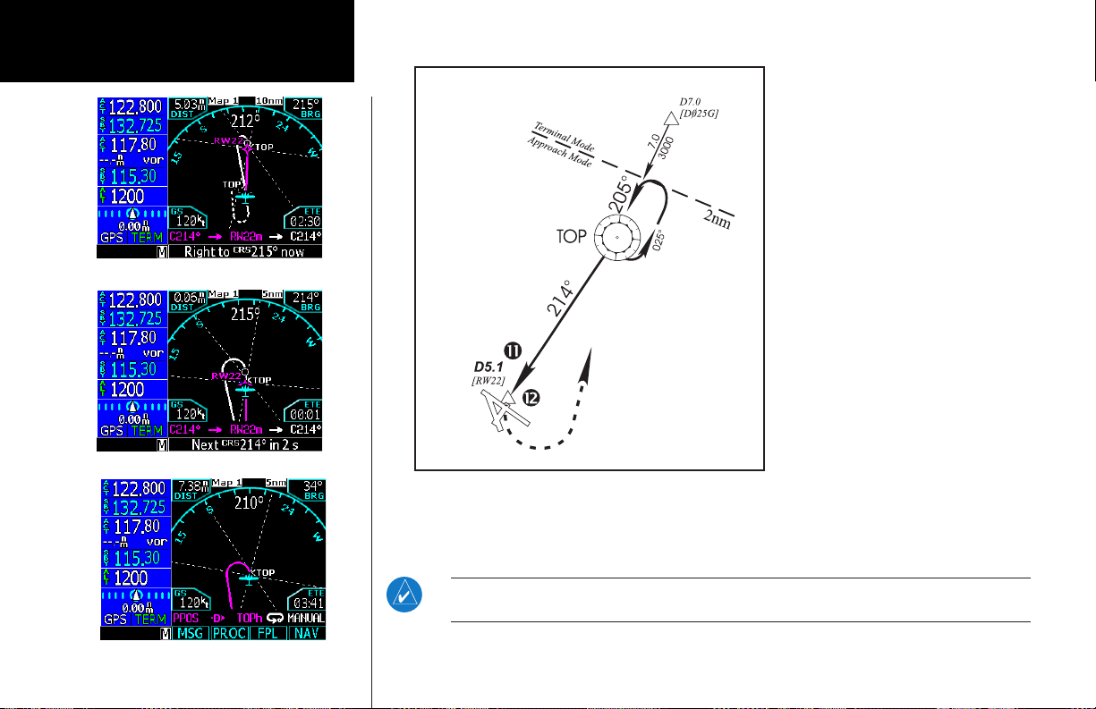
Basic Operation
Procedures
DO NOT USE FOR
NAVIGATION
11. The Missed Approach consists of a course to altitude leg of 214° to an altitude of 1281 feet. Press
the CDI key to switch the CDI source from the VOR back to GPS. Fly the guidance provided by the GNS
480. It will automatically sequence at the MAP to the missed approach. After reaching 1281 feet, the
GNS 480 will automatically sequence direct to the TOP VOR for the hold.
8. As you approach the FAF, a waypoint
message (“RIGHT TO TRK 214°”) on the
bottom of the screen appears. As this is not
a GPS overlay, press the CDI key to switch
from the GPS to the VOR source for the
CDI. Select this course on the CDI (or HSI)
using the OBS knob and turn to the final
course segment (FAF to MAP) heading.
9. As you cross the FAF, the destination
sequences to the MAP (“RW22”, the
runway threshold). With the needle
centered, fly toward the MAP, observing
the altitude minimums dictated by the
approach plate. When viewing the Map
Page, you’ll note that the final course
segment is displayed in magenta (the
active leg of the flight plan always appears
in magenta) and a dashed magenta line
shows the first leg of the missed approach.
10. As you approach the MAP, a waypoint
message with countdown time appears on
the bottom of the screen.
NOTE: For roll steering-capable autopilots: after crossing the MAP, you may reengage the
autopilot roll steering to allow the GNS 480 to fly the Missed Approach automatically.
86
Page 95

Vectors To Final
Let’s take a second look at the “VOR 22” approach into Billard Municipal (KTOP). Instead of following the
DME arc, ATC tells you to expect vectors onto the final approach course. There are several ways to select
“vectors to final” (VTF) with the GNS 480. The two options below normally require the least workload to
accomplish:
•Whentheapproachisrstselected,choose“VECTORS”fromthetransitionseld.
•Loadafullapproach—includingtheIAFfromthetransitionswindow.
•Then,whencleared,pressPROC and select VTF (Vectors-To-Final).
NOTE: If a transition with a procedure turn or course reversal in holding is selected, and ATC
subsequently vectors you to the final approach course, VTF mode will automatically remove the
procedure turn and make the in-bound course active for the intercept.
To select “VECTORS” from the transitions field:
1. Press the PROC key and select the “VOR 22” approach.
2. From the transitions field, select “VECTORS.”
3. Review the modified flight plan and execute it.
To activate vectors-to-final from the procedures page:
Regardless of what transition was selected, press the VTF function smart key to activate vectors to final.
Basic Operation
Procedures
When you are in the Terminal area, you
may be directed to fly a vector to final
approach.
1. Press FN and then PROC.
2. Press VTF.
3. Follow the guidance from the GNS 480 as
the inbound course to the Final Approach
Fix (FAF) is now active.
87
Page 96

Basic Operation
Procedures
DO NOT USE FOR
NAVIGATION
4. ATC instructs you to turn right to a heading of 115°.
5. ATC instructs you to turn right to a heading of 175° to intercept the final approach course. As you
converge with the final approach course the needle moves toward the center. In the illustration, the
needle has returned to the on-screen CDI and your current position is less than 1.0 nm right of the
final approach course.
With “Vectors-To-Final” selected, the CDI needle
remains off center until you’re established on the final
approach course. The Map Page displays an extension
of the final approach course in magenta (remember, magenta is used to depict the active leg of the flight plan)
and “VTF” is annunciated in the lower left corner of the
screen (as a reminder that the approach was activated
with vectors-to-final). In this example, we’ll assume
ATC vectors result in a rectangular course to intercept
final, as follows:
1. Within 30 nautical miles of KTOP, the GNS 480
switches from en route mode to terminal mode and the
CDI scale transitions from 2.0 to 1.0 nautical miles, full
scale deflection.
2. If you haven’t already done so, activate VTF mode
and set the inbound course on the CDI. This allows the
GNS 480 to guide you to the final approach course.
Verify that “VTF” is annunciated.
3. ATC instructs you to turn left to a heading of 025°.
This places you parallel to the final approach course in
the opposite direction. CDI needle deflection is to the
left.
Flying a Vectored Approach
88
Page 97

6. As the CDI needle centers, make
any remaining course corrections to
establish yourself on the final approach
course.
7. As you approach the FAF, a waypoint
alert on the bottom of the screen
(“RIGHT TO TRK 214°”) appears. Make
any course adjustments necessary for
the final course segment (FAF to MAP).
8. As you cross the FAF, the destination
sequences to the MAP (“RW22”). With
the needle centered, fly toward the
MAP, observing the altitude minimums
dictated by the approach plate.
9. As you approach the MAP, a waypoint
message appears on the bottom of the
screen and an audio message occurs.
10. See the Flying the Missed Approach.
In VTF mode, if you are within 45° of the inbound course and you are on the TO side, the
“SUSP” mode will turn off and return to normal sequencing.
DO NOT USE FOR
NAVIGATION
Basic Operation
Procedures
89
Page 98

Basic Operation
.-
.-
.-
-!.5!,
&!&
6,/#
6,/#
'03
'03
Procedures
Auto
within this area
Switch to VLOC
ILS Approaches
Precision approaches can be performed with the GNS 480’s built-in VLOC (VOR/localizer/glideslope) receivers.
The GPS receiver can be used for guidance prior to reaching the final approach fix, but once there, the proper
frequency must be selected on the VLOC window (left side of screen) and the CDI output set to “VLOC”.
The GNS 480 can be set to automatically switch the external CDI output from GPS to VLOC as you intercept the final approach course. When the ILS approach is activated (and the correct ILS frequency is active
in the VLOC window), the GNS 480 automatically switches within 1.2 nautical miles left or right of the final
approach course. The following criteria must be met for the CDI autoswitch to occur based on your present
position: 1) the aircraft must be before the FAF, 2) within 15 nm of the FAF, 3) aircraft and ground track is
within 90
° of the final approach course, 4) within 1.2 nm of cross track error, 5) there are no
course reversals in the flight plan to be performed, and 6) the ILS frequency is valid with a
decoded ident.
The illustration shows both multiple locations along the approach path and the CDI selection that you can expect: GPS or VLOC. Within the area of the shaded box, the automatic switch from GPS to VLOC should occur.
The pilot will receive a message “SWITCHING FROM GPS TO NAV.”
NOTE: If an unusual approach intercept is made, the GNS 480 may not be able to autoswitch,
based on the required criteria. In this case, press the CDI key to manually switch from GPS to
VLOC.
The automatic switch from GPS to VLOC is not immediate, but instead occurs gradually to prevent abrupt
CDI changes when coupled to an autopilot. The CDI selection can also be changed manually by pressing the
CDI key. If a missed approach is required, the GNS 480 will automatically switch back to GPS for the missed
approach. If you fly the approach again using VTF mode or with a procedure turn, autoswitch will reset and
switch again. To prevent automatic ILS CDI selection, choose the “Manual” ILS CDI setting, (the factory default
setting is “Auto”, which enables the automatic switch to VLOC).
90
Page 99

Selecting an ILS Approach
For this example, we’ll use a flight
from Laughlin Bullhead (Arizona)
Flagstaff (AZ) Pulliam
ILS DME Rwy 21
International to Flagstaff Pulliam
(KFLG) and select the ILS runway
21 approach. “SHUTR” intersection is selected as the IAF, which
includes an outbound leg and a
procedure turn. Of course, vectors-to-final could also be selected,
as previously described.
1. Select Flagstaff Pulliam
(KFLG) as your destination,
with the DEST key or build
a new flight plan.
2. Press the PROC key
and select the “ILS 21”
approach.
3. From the transitions field,
select “SHUTR” as the IAF.
Review and execute the modified flight plan. Go direct to SHUTR when cleared for the approach.
4. When you “Execute” an ILS approach, the ILS frequency is automatically checked. If the correct
frequency is not in the active field, you will receive a message informing you of the correct frequency.
Press Menu/Enter to put the frequency into the active field or CLR to put it into the standby field.
5. A reminder message appears, indicating that GPS can only be used for approach monitoring. As
mentioned previously, you need to use the VLOC receiver for this approach. Press CLR to acknowledge
the message.
DO NOT USE FOR
NAVIGATION
Basic Operation
Procedures
91
Page 100

Basic Operation
Procedures
Flying the ILS Approach
When you “Execute” an ILS approach, automatic
switching of the external CDI is enabled (unless
turned off from the CDI/Alarms line on the SystemConfiguration Page). When you are established on the
inbound course to the FAF, the external CDI guidance
automatically switches from “GPS” (shown in green
text) to “LOC”. If you have forgotten to tune the ILS
frequency, automatic selection of “LOC” does not occur.
1. Within 30 nautical miles of KFLG, the GNS 480
switches from en route mode to terminal mode
and the CDI scale transitions from 2.0 to 1.0
nautical miles, full scale deflection.
2. As you approach the IAF (SHUTR), a waypoint
message (“LEFT TO TRK 030°”) appears on the
bottom of the screen.
3. Verify that the ILS frequency ident has been automatically decoded on the display.
4. As the distance (DIS) to the IAF approaches zero, the message is replaced by a turn advisory that
counts down 10 seconds prior to the turn.
5. Fly the outbound course (030°), keeping the needle centered on the external CDI (or HSI).
6. Once you have flown approximately one minute past SHUTR intersection, the message “RIGHT TO TRK
075°” appears in the lower right corner of the screen.
DO NOT USE FOR
NAVIGATION
92
 Loading...