

Page 1
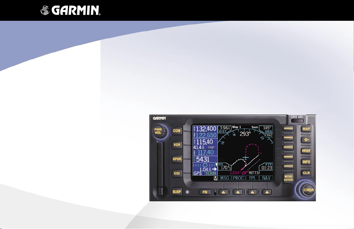
GNS 480
GNS 480
TM
TM
color gps/waas/nav/comm
color GPS/WAAS/NAV/COM
quick reference
quick reference
Page 2
KEYS AND KNOBS
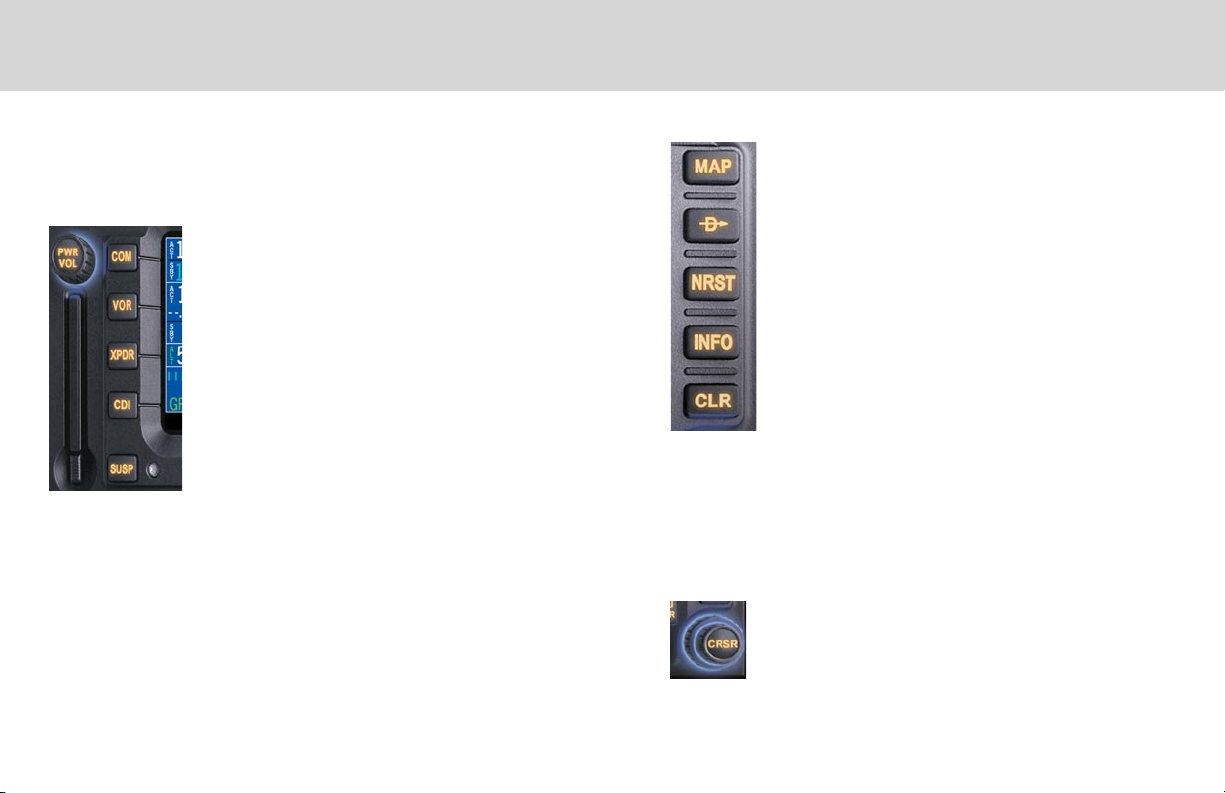
Left-Hand Keys and Knobs
The Power/Volume knob controls unit power and radio volume (Nav
and Com). Push the knob in to turn the unit on. Pull the knob out to
turn the unit off. When in Com or Nav radio modes, turn the knob to
control audio volume.
The COM key activates control of the Com radio. The Com radio
window on the left side of the display will be outlined.
The VOR key activates control of the Nav radio. The Nav radio window on the left side of the display will be outlined.
The XPDR key activates control of an external transponder, if available. The
remote transponder window on the left side of the display will be outlined.
The CDI key toggles between the GPS or Nav receivers as the source
driving the CDI. GPS or Nav is indicated in the lower left side of the
display.
The SUSP key toggles between automatic or suspended leg sequencing.
The Data Card ejector is located on the lower left corner of the unit.
Software and databases can be updated by replacing the data card. Never
remove or insert the data card when the unit is powered on. With the
power off, press the ejector button to partially eject the data card and
carefully pull it the rest of the way out. Note the orientation of the card.
It will only go back in when turned in the right direction. Replace the
data card by carefully pressing it into the slot completely. Do not force
the card, if it doesn’t go in easily it probably isn’t turned the right way.
The MENU/ENTER key is used as an Enter key to approve an operation
or complete data entry or as a Menu key to display the available Menu
items for the active function.
The Large and Small concentric knobs are used to edit and select information. Turn the Large knob to move the cursor. Turn the Small knob to
select characters or options.
Right-Hand Keys and Knobs
The MAP key activates the Map mode. The moving map
will cover the right two thirds of the display.
The Direct-To key activates the direct-to function that
allows you to enter a destination waypoint and establish a
direct course to the destination.
The NRST key activates the nearest waypoint search function that allows you to find the nearest 20 waypoints of
each type.
The INFO key provides access to a wide variety of information about the selected waypoint.
The CLR key is used to erase information or clear an entry.
The Cursor knob activates an editing cursor by pressing the
Small knob in and then turning it. When the Map function
is active, pressing in on the Cursor knob activates Panning
mode.
2
Page 3
KEYS / POWER ON
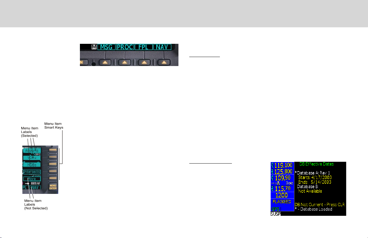
Bottom Row Keys
The Function Smart
Keys are
the four
unlabeled keys below the right two-thirds of the display. The
functions are shown on the display above each Function Smart
Key. Press the Function Smart Key below the function name
shown above the key to select the displayed function.
Each press of the FN key will step through the available functions.
Menu Items
The Menu Item smart keys are on the right side of the
unit next to the display. A list of labels customized for
each function or mode are shown on the display adjacent to each Menu Item key. Press the Menu Item key
to select the displayed choice.
Powering Up the GNS 480
Starting Up
The GNS 480 performs internal checks and shows the status of the tests during
start up. The startup screen, owner name (if entered), testing, position, and
database information shows on the screen for several seconds and then shows
the first Map page.
Power Up
1. Push the PWR/VOL knob in to turn on power.
2. When the position display appears, you can press CHG to manually enter
your present position or just wait a few seconds for the GNS 480 to
establish your position. The full power up sequence takes 2-3 minutes.
3. The GNS 480 performs a number of tests at startup to ensure proper
operation. You may press SKIP to bypass the startup tests, however,
completing these tests is required for IFR flight. Observe the tests and
needle swings for proper operation.
Database Check
The GNS 480 verifies the integrity and
expiration date of the database. Up to
two database cycles are supported. The
GNS 480 will load the appropriate current database cycle and also let you know
if a database is not current (dates invalid
or corrupt) with a message in amber.
3
Page 4
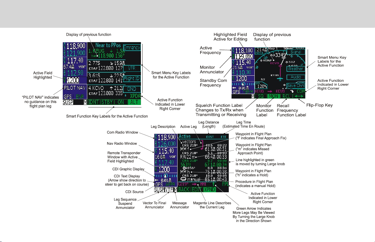
Transponder Active
SCREEN LAYOUT EXAMPLES
Active Flight Plan Page (Expanded)
4
Page 5
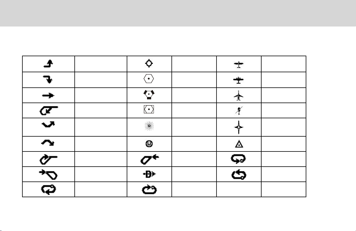
DISPLAY SYMBOLS
The following symbols are used on the map display to depict active legs of flight, waypoint types, and your aircraft.
Turn Left for next flight
plan leg
Turn Right for next
flight plan leg
No course change VORTAC Ownship - Jet
Left Procedure Turn
Outbound
Arc to the Left NDB Flight Plan
Arc to the Right User Waypoint Intersection
Left Procedure Turn
Inbound
Entering Procedure Turn
Right
Right Hand Holding
Pattern Outbound
Airport Ownship - Single
VOR Ownship - Twin
VOR-DME Ownship -
Helicopter
Waypoint
Entering Procedure
Turn Left
Direct-To Left Hand Holding
Right Hand Holding
Pattern Inbound
Left Hand Holding
Pattern Inbound
Pattern Outbound
5
Page 6
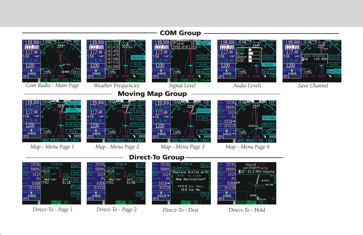
PAGE SELECTION
6
Page 7
PAGE SELECTION
7
Page 8
PAGE SELECTION
8
Page 9

COM AND NAV RADIO
Comm Radio (COM)
• Press COM to activate Com mode.
• Turn Large knob to change MHz.
• Turn Small knob to change kHz.
• Press <—> to toggle Active and Standby frequency.
• Press SQ to toggle activation of auto squelch.
• Press MON to monitor Standby frequency.
• Press Com again to return to previous
function or page.
• Press Menu/Enter for Menu items.
Press Signal to view levels.
Press Weather to view frequencies.
1. Turn Large knob to highlight.
2. Press <-SBY or <-A->.
Press Audio to view and edit levels.
Press Save Chnl.
1. Turn Large and Small knobs to choose name and frequency.
2. Press Menu/Enter to save.
• Press RCL to recall (Recent) stored frequencies.
Turn the Large knob to select frequencies.
Press User to view list of User-created frequencies.
Press Emrgncy to insert the Emergency frequency into Standby.
Press <SBY or <-A->.
VOR/ILS Radio (VOR)
• Press VOR.
• Turn Large knob to change MHz.
• Turn Small knob to change kHz.
• Press <—> to toggle Active and Standby frequency.
• Press Menu/Enter for Menu items.
• Press ID to toggle Nav Audio - ID/Voice.
• Press MON to monitor Standby frequency.
• Press RCL to recall (Recent) stored frequencies.
Turn the Large knob to select
frequencies.
Press User to view list of User-
created frequencies.
Press <SBY or <-A->.
• Press Menu/Enter for Menu items.
Press Test Log to enter calibration
info.
1. Turn Large and Small knobs to modify calibration info.
2. Press Menu/Enter to save.
Press ID/TO/FR to view the bearing To/From the VOR or Ident.
Press Audio to view or edit levels.
Press Save Chnl.
1. Turn Large and Small knobs to choose name and frequency.
2. Press Menu/Enter to save.
• Press Com again to return to previous function or page.
9
Page 10

DIRECT-TO NAVIGATION
Direct-To Navigation
Press the Direct-To key to get to the Direct-
To function which allows you to quickly
navigate from your present position directly
to a selected waypoint. You can also use this
function to make changes to a flight plan, set
up a user-defined holding pattern, sequence
directly to a selected leg in your flight plan,
fly a Course To or Course From a selected
waypoint, or activate the OBS function.
ActFP
With the ActFP key highlighted, turn the Large knob to highlight waypoints in
your active flight plan. Press the menu item smart key on the right side of the screen
to perform the selected action.
DB
Press the DB key to select any waypoint from the database. Use the Large and
Small knobs to select the waypoint.
Direct
The Direct Menu item key activates the direct course to the selected waypoint from
your present position.
1. When you press Direct-To, the default waypoint shown will be the active
(highlighted) waypoint in your flight plan (unless another waypoint is
highlighted in another operation, then that waypoint would be used). You
can turn the Large knob to select a different waypoint in your flight plan.
2. You may select a waypoint that is not in your flight plan by pressing the DB
key and then use the Large and Small knobs.
3. Press the Direct key to navigate directly to the selected waypoint.
4. Select a waypoint nearest you location using the NRST function.
10
FlyLeg
With the FlyLeg menu selection you can activate a particular leg of your flight
plan for navigation guidance. If you have picked an invalid leg, a message will
warn you.
1. Press the Direct-To key. Press the ActFP key, if necessary.
2. Select the desired leg of your flight plan with the Large knob.
3. Press the FlyLeg menu item key to activate guidance to the selected Leg.
Intercept Course-To a Waypoint
Course-To operation allows you to add an intercept course to the selected
waypoint either in your active flight plan
or to a waypoint in the database. Upon
reaching the selected waypoint, the flight
plan will sequence to the next waypoint
in the flight plan normally.
1. Press the Direct-To key.
a. Press ActFP and turn the
Large knob to select a
waypoint in your flight plan.
or
b. Press DB to select a waypoint not in your active flight plan with the
Large and Small knobs.
2. Press the CrsTo menu item key (you may have to press the More menu
item key first.
3. Change the course bearing, if desired. Use the Large knob for 10° steps
and the Small knob for 1° steps.
4. Press Menu/Enter.
Page 11

DIRECT-TO NAVIGATION
Intercept Course-From a Waypoint
Course-From operation allows you to navigate from a waypoint on a selected
course. When the Course From operation is executed, the CDI will indicate
FROM and the flight plan will go into Suspend mode (the SUSP annunciator
will appear); it will not automatically sequence the flight plan waypoints. The
airplane will track outbound on the selected radial until instructed otherwise.
1. Press the Direct-To key.
2. Press ActFP and turn the Large
knob to select a new waypoint
from the flight plan or press DB
and select a waypoint from the
database, if desired.
3. Press the CrsFr menu item key
(you may have to press the
More menu item key first.
3. Change the course bearing, if
desired. Turn the Large knob to change the course 10° value. Turn the
Small knob to change the course 1° value.
4. Press Menu/Enter.
OBS Mode
When the OBS mode is active, use the CDI/HSI control to set an intercept course
to any waypoint as you would with a radial for a VOR.
1. Press Direct-To. Highlight the desired waypoint in your active flight plan
with the Large knob. For waypoints not in your flight plan, select a new
waypoint with the Large and Small knobs, otherwise the destination
waypoint is used.
2. Press OBS. Now use the external CDI/HSI resolver to control the selected
course. Press SUSP when the course is complete, which allows normal
sequencing.
Direct-To a Waypoint in Your Active Flight Plan
1. Press Direct-To.
2. Press the ActFP function smart
key.
3. Use the Large knob to select the
waypoint in the flight plan.
4. Press the Direct menu item smart
key. The GNS 480 will navigate
direct to the selected waypoint.
Direct-To a Waypoint Not in Your Active Flight Plan
1. Press the Direct-To key.
2. Press the DB function smart key.
3. Use the Large and Small knobs to select the waypoint ident or name.
4. Press the Dest menu item smart key and then press Menu/Enter. Now,
fly direct to the selected waypoint.
5. To set an approach, press the PROC function smart key and then the
Appch menu item smart key.
6. Use the Large and Small knobs to select the approach and then press
Menu/Enter.
7. Press the EXEC function smart key and then Menu/Enter to execute the
change in your flight plan.
11
Page 12

MOVING MAP MODE (MAP)
Moving Map Mode
The Map mode provides a moving map for a graphic display of your flight
including the surrounding area as well as navigation information. Maps are
generally drawn with aircraft Ground Track at the top of the display (Up). True
North is at the top of the display for the non-moving maps for inserting holds,
procedures, and intercepts. Press MAP twice to go to Map page 1.
1. Press MAP to reach Map mode. Radio, Nav, Transponder, CDI,
Annunciator, or pilot-customized information is shown on the left side of
the display and the map display is shown on the right side.
2. There are four Map pages that you select by turning the Large knob.
3. Turn the Small knob to change the Map scale. Map pages 2-4 allow you
to customize the Nav display items on the left side of the display and map
display detail. Using the Nav Data and Sel Data functions allows you to
select the data fields.
4. Press Menu/Enter to view the Menu items for the choices to customize
your display.
5. Press the key next to the Menu item to change the values.
6. Press the More key to go to the next page of Menu items.
True North
The Map can be referenced to True North after
setting the Magnetic Variation to 0° in the Configuration section of System mode. When set to
True North, the degree values on the map display
will show a “T” along with the degree symbol. To
reset magnetic variation for normal
See “Setting Nav Info in Map Mode” for details.
12
Page 13

MAP NAV INFO (MAP) / PAN MODE (PAN)
Setting Nav Info in Map Mode
You can customize the Nav information displayed on the left side of the display
for Map Mode pages 2, 3, and 4. You can select these options as described below.
1. Press MAP to reach Map mode.
2. Turn the Large knob to select pages 2-4. You can’t change the Nav
information options for page 1.
3. Press the Menu/Enter key.
4. Press the More selection key
until the Nav Data selection is
available.
5. Press the Nav Data selection
key.
6. Press the Sel Data selection key
to activate selection of options of
Nav Data information.
7. Turn the Large knob to highlight the desired Nav Data item. Turn the
Small knob to change the displayed option.
8. Press Menu/Enter when you have completed your selections.
9. If desired, turn the Large knob to another Map Mode page and
customize that page.
Activate the Panning feature by pressing the
PAN key or the CRSR button on the Small
knob when in Map mode.
The cross hair cursor (+) starts at your present position when starting the Pan mode.
Turning the Large knob pans left/right of pan
track. Turn the Small knob to pan forward
and back of pan track. A green line is drawn
between your present position and the cross
hair position. Range and bearing to the cross hair position from your present position
and the Lat/Lon of the cross hair position is shown at the bottom of the map display.
Range
Press the Range key to highlight the Range menu item. When Range is selected, turn
the Small knob to change the map range to zoom in or out at the cross hair position.
MRK Press MRK to create a User Waypoint at the cursor position.
Create a New User waypoint
User waypoints allow you to create unique waypoints not already present in the
database.
1. While in the Pan function, press MRK.
2. Press Menu/Enter to save the displayed user name.
or
3. Create a name of your choice and add other information as desired using
the Small knob to change characters and the Large knob to move the
cursor. Press CLR to delete a highlighted character. Then, press Menu/
Enter to save the information.
Pan Mode
13
Page 14

USER WAYPOINTS (USER) / SYSTEM MODE (SYS)
User Waypoints (USER)
The GNS 480 can hold up to 500 user-defined waypoints. These waypoints can
be based on either lat/lon position or range and bearing from a reference point.
In the User Waypoint function, you can create new waypoint, edit existing ones,
or search for a User waypoint.
Creating or Editing a User Waypoint
1. Press FN and then the USER key to start the User Waypoint function. You
can also create User waypoint by
using the PAN function.
2. Press the NEW or EDIT key.
3. Use the Small and Large knobs
to name or edit the waypoint
name. You can also set a range
and bearing from a reference
waypoint.
4. Turn the Large knob to go to
each field on the page and edit the values.
5. Press Menu/Enter when finished.
Searching for a User Waypoint
1. Press FN and then the USER key to start the User Waypoint function.
2. Press the SEARCH key.
3. Use the Small and Large knobs to select the waypoint name. You can
also search through a given field by pressing the CRSR knob, moving to
a field with the Large knob, and then searching within a field by turning
the Small knob.
4. Press Menu/Enter when finished.
14
System Mode (SYS)
1. Press the FN key and then the SYS function smart key to reach the
System mode.
2. Press the GPS, VERS, or CNFG function smart keys to go to each page.
GPS
GPS/WAAS status, GPS Time, satellites
available with overhead view, and signal
strength of the available satellites are
shown.
VERS (Software Versions)
Unit serial number and software versions are shown. This information
should be noted before calling customer
service.
CNFG (User Configuration)
The User Configuration function allows
you to set values for your aircraft.
1. Turn the Large knob to highlight
the value.
2. Press the CRSR knob in and then
turn the Small knob to change
the value.
3. Press the Menu/Enter key to
save the value.
Page 15

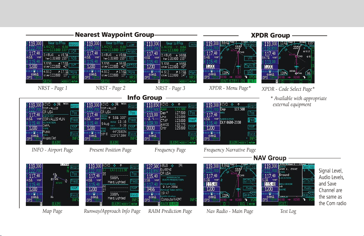
NEAREST WAYPOINT (NRST)
Nearest Waypoints (NRST)
The Nearest Waypoint Search function allows you to search for the 20 waypoints
nearest to your present position in each waypoint type. There are eight waypoints
types: Airport, VOR, NDB, INT, User, FSS (Flight Service Station), Airspace, and
Nearest Frequency
While viewing the Nearest waypoints that have frequency information, you can
transfer the displayed frequency to the Active or Standby frequency. The
GNS 480 automatically knows if it is a Com or a VOR frequency.
Air Route Traffic Control Center (ARTCC). The last Menu item lets you set limits
to select a range of airport types to show up for the Nearest Airport type. You can
then look up information about the selected waypoint by pressing INFO or fly
direct to it by pressing the Direct-To key.
1. Press NRST to display the Nearest waypoints. The default type is airports.
2. The Nearest waypoint type labels are shown on the right side of the
display. Press the menu item key next to the waypoint type label that you
want.
3. Turn the Large knob to highlight (green) the waypoint you want to select.
4. You can press INFO to learn more about the highlighted waypoint or press
Direct-To to fly direct to that waypoint.
Nearest Airport Search Limits
1. Press NRST, press Menu/Enter, and then press More to show the Limits
menu item.
2. Press the Limits menu item smart key.
3. Turn the Large knob to move between Runway Type, Runway Length, and
Night Lighting.
4. Turn the Small knob while highlighting a field to view the options.
5. Press Menu/Enter to accept the search limits.
1. Press NRST.
2. Press the menu item key for
the waypoint type you want to
search.
3. Turn the Large knob to scroll
thru the list of nearest waypoints,
such as Airport, VOR, User if
a frequency is present, FSS, or
ARTCC. Highlight the desired
waypoint.
4. Press INFO and then Freqs. Turn
the Large knob to scroll through
the list. For frequencies with an
asterisk (*), press Freqs again
for narrative information.
5. Press <-SBY to insert the
highlighted frequency into the
Standby position or <-A-> to
insert the frequency into the
Active position.
15
Page 16

WAYPOINT INFO (INFO)
Waypoint Information (INFO)
Info mode allows you to view information about the selected waypoint. Examples of selecting a waypoint can be:
highlighted waypoint in the flight plan, waypoint selected
from Nearest Waypoint list, waypoint selected in Pan
mode, or a waypoint selected from the database. When
viewing information that contains Com or VOR frequencies, pressing the <-SBY or <-A-> keys will insert the
highlighted frequency into the appropriate radio.
Viewing Waypoint Information
1. With either the active waypoint or with the desired
waypoint highlighted, press INFO.
2. Press the menu item on the right side of the screen
to select the type of information.
3. Turn the Large knob to scroll, if more than one
page of info is available.
4. Press INFO again to return to the previous mode.
16
Page 17

CHECKLISTS (CHK) / MESSAGES (MSG)
Checklist (CHK)
The Checklist function allows you to create up to eight checklists with up to 100
lines of text in each. You can use this feature as a method to create customized
checklists for in-cockpit review.
Using Your Checklist
Creating a New or Editing an Existing Checklist
1. Press FN and then the CHK key to start the Checklist function.
2. Press the NEW or EDIT key. Press the CRSR knob in and use the Small
and Large knobs to name the new list. Press Menu/Enter when
finished.
3. With the name of your new list highlighted, press the EDIT key.
4. Turn the Small knob to choose the desired checklist item. See the
following table for available checklist items. If you want to make your
own item, press the CRSR knob in and use the Small and Large knobs
to name the new item. Press Menu/Enter when finished.
5. Then, turn the Large knob to the checklist result for that item. Turn the
Small knob to choose the desired checklist result. See the following table
for available checklist results. If you want to make your own result, press
the CRSR knob in and use the Small and Large knobs to name the new
result. Press Menu/Enter when finished.
6. Turn the Large knob to the next checklist item. Continue with the process
in the previous steps until finished with your list. Press the LIST key or
other key to leave the Checklist function.
Move a Checklist
1. Press FN and then the CHK key to start the
Checklist function.
2. Turn the Large knob to highlight the desired
list and then press Enter/Menu. The
selected list will be displayed with the first
line highlighted.
3. Press the CHK key, or the Menu/Enter
key, as you check each item in the list. After
pressing the CHK key, the next item in the
list will be highlighted.
4. After the last item is checked, the >CHECKLIST COMPLETE< line will
be highlighted. Press CHK to check this item and return to the main
Checklist page.
1. Press FN and then the CHK key to start the Checklist function.
2. Press the MOV key.
3. Turn the Large knob to the position in the order of lists where you want
to put the highlighted list and press the Menu/Enter key.
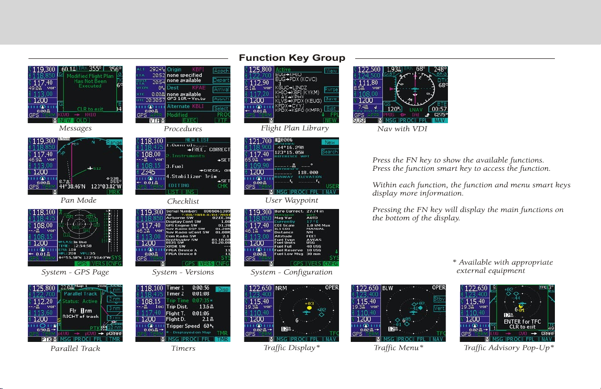
Messages
1. Press FN and then the MSG function smart key.
2. Turn the Large knob or press the New or Old function smart keys to
switch between Old or New messages.
3. Turn the Small knob to view the available messages.
17
Page 18

FLIGHT PLANNING (FPL)
Create a New Flight Plan
1. Press FN and then the FPL
function smart key.
2. Press the New function smart key.
3. Use the Large and Small knobs
to select the Origin waypoint and
then press Menu/Enter.
4. Use the Large and Small knobs
to select the Destination waypoint
and then press Menu/Enter.
5. Highlight (green) the departure waypoint and insert a Standard
Instrument Departure (SID) waypoint or airway. Continue until the flight
plan is complete. You may add text comments to the flight plan.
6. The flight plan is named and saved in the Library by the Origin and
Destination waypoints.
7. Pre the EXEC function smart key to execute the flight plan and make it
the active flight plan. Press Menu/Enter to make your new flight plan
the active flight plan.
Activate a Flight Plan
1. Press the FPL function smart key to display the Flight Plan library. If the
active flight plan is displayed, press the BACK function smart key.
2. Turn the Large knob to the desired active flight plan.
3. Press the EXEC function smart key.
Delete the Active Flight Plan
1. Press the FPL function smart key to display the Flight Plan library.
2. Turn the Large knob if necessary to highlight the active flight plan.
3. Press the CLR key.
18
Edit a Flight Plan
Changing Origin, Destination, & Alternate Waypoints
1 Press FN and then the FPL
function smart key.
2. Turn the Large knob to highlight
the flight plan to edit and press
the EDIT function smart key.
3. Turn the Large knob to highlight
the flight plan name.
4. Press the Origin or Dest or
Alternate menu item smart keys
to change these waypoints.
5. The flight plan is renamed and shown in the Library by the new Origin and
Destination waypoint names.
6. Press the SAVE function smart key to save the flight plan.
Inserting a Waypoint or Airway in Your Flight Plan
1. Highlight a waypoint with the Large knob.
2. Press the ->Wpt menu item smart key to insert another waypoint.
3. Use the Large and Small knobs to select a waypoint and then press
Menu/Enter. The new waypoint will be inserted after the highlighted
waypoint or en route intersection.
4. If the waypoint is on an airway, Airways will be available to insert into
your flight plan. Press the ->Arwy menu item smart key. Use the Large
and Small knobs (or smart keys) to select the Airway and exit waypoints.
Press Menu/Enter.
5. Press the XPND function smart key to view all of the waypoint inserted
automatically by inserting the airway.
Page 19

FLIGHT PLANNING (FPL) / NAV-VDI (NAV)
6. You may remove an entire airway by highlighting it in the compacted
(unexpanded) view with the Large knob and then pressing the CLR key.
Deleting a Waypoint or Airway in Your Flight Plan
1. While editing your flight plan, turn the Large knob to highlight the
waypoint or airway you want to delete.
2. You can edit in the expanded or
compressed view of your flight
plan. In the expanded view,
you can select each individual
segment of your plan. In the
compressed view, you can
select and remove waypoints
or airways that will also include
associated part of that waypoint
or airway.
3. Press the CLR key.
4. Press the SAVE function smart
key to save your changes and
return to the flight plan library.
Nav Display (NAV)
The GNS 480 displays a track-based Horizontal Situation Indicator (HSI) view.
The Nav function is reached by pressing the NAV smart function key. The layout,
annunciations, and nav data are similar to Map mode. Distance to the destination is shown in the top left corner. Bearing to the destination is shown in the
top right corner. Current Ground Speed (GPS determined) is shown in the lower
left corner. The Estimated Time En Route from your current position to the next
waypoint is shown in the lower right corner. You may also select the categories
of Nav Data shown on the left side of the display. When vertical guidance is
provided, a vertical deviation indicator is shown on the left side of the display.
The CDI/VDI is driven by one of the following: GPS data if GPS CDI annunciation is selected or Nav radio data if LOC, VOR, or ILS annunciation is selected.
The HSI is always oriented to GPS track. In some cases, GPS track may not line
up perfectly with a VOR radial, but wind compensation is not necessary.
19
Page 20

PROCEDURES (PROC)
Adding SIDs, STARs, and Approaches
SIDs are associated with the departure airport. STARs and IAPs are associated
with the destination airport.
After creating your flight plan, you can select an approach, departure, or arrival
procedure so the GNS 480 can guide you through the procedure.
1. Press the PROC function smart
key for Procedure Mode. The
Origin and Destination waypoint
of your active flight plan are
shown.
2. Press the Depart menu item
smart key to select the Departure
procedure. If available, select
the departure runway (with the
Small knob or the menu item keys).
3. Turn the Large knob to move between fields and turn the Small knob to
select the transition. Press Menu/Enter to accept the procedure.
4. Press the BACK function smart key to return to the Procedures mode.
Depending on the procedure for your destination, press the Destination
Arrival or Appch menu item
smart key.
5. Choose the transition and the
runway by moving to a selection
with the Large knob and listing
the choices with the Small knob.
Press Menu/Enter to accept the
transition.
6. If desired, select an alternate airport by pressing the Alternate Select
menu item key.
7. Press EXEC to activate the procedures for your flight plan.
Perform a RAIM Prediction
RAIM prediction predicts if GPS coverage is available for any waypoint. This is
used when WAAS satellites are not available.
1. Highlight a waypoint in the active flight plan or select a waypoint from
the database. Press INFO and then press the RAIM function smart key
when it is shown.
2. Press the CRSR knob in. One
of the fields will be highlighted.
Change the values of the Arrival
Date and/or Arrival Time (in UTC
time) with the Small knob while
moving to a value with the Large
knob. The default calculation
is the ETA to the last waypoint
in the active flight plan. When
selecting a waypoint from the database other than one in the active flight
plan, the default calculation is the ETA from the present position to the
waypoint.
3. After setting the values, press the Menu/Enter key to compute the RAIM
prediction.
20
Page 21

PROCEDURES (PROC)
Flying the Missed Approach
The GNS 480 will automatically sequence to the missed approach. Fly the
heading legs manually. When the course leg becomes active, press the SUSP
key to “unsuspend” waypoint sequencing. You may reengage roll steering on
your autopilot. The GNS 480 will then fly the Hold Entry and Holding automatically. Non-roll steering autopilots or manual flight may be accomplished
by flying to the CDI.
1. Follow the missed approach procedures, as published on your approach plate.
The GNS 480 guides you to the Missed
Approach Point holding pattern.
2. A message on the bottom of the
screen recommends entry procedures
for the holding pattern (i.e., “HOLD
DIRECT”, “HOLD PARALLEL”, or “HOLD
TEARDROP”). You may use the holding
pattern dashed magenta lines for
reference in manual flight. The hold is
automatically sized for a one minute
leg makes corrections for winds aloft with an AOC input. Roll steering-capable
autopilots will fly the hold and hold entry automatically.
3. The GNS 480 provides course guidance only on the inbound side of the
holding pattern. When leaving the holding pattern to re-fly the approach (or
another approach) press the PROC key to activate Vector To Final (VTF) mode
for vectors or for a full procedure direct to the airport using the Direct-To key.
Note: In the event that you wish to divert direct to another destination,
use the Destination (DEST) function on the Direct-To page.
Vectors To Final
When you are in the Terminal area, you may be directed to fly a vector
to final approach.
1. Press FN and then PROC.
2. Press VTF.
3. This extends the inbound course from the FAF for the intercept.
21
Page 22

TRANSPONDER (XPDR)
Remote Transponder Mode C/S(XPDR)
Change Ident
1. Turn the Large knob to highlight numbers.
2. Turn Small knob to change numbers.
3. Automatically saved after selecting 4th number or press Menu/Enter.
or
1. Press CRSR knob in.
2. Press 0 - 7 numbers in the order desired.
• Press Menu/Enter to view options.
• Press Emrgncy then Menu/Enter to insert 7700 Squawk code.
• Press VFR to insert 1200 Squawk code.
• Press TrgrSpd to select Trigger Speed to automatically activate transponder when in Auto
mode. *
1. Turn Large and Small knob to edit speed.
2. Press Menu/Enter to save.
• Press Auto to toggle Auto Activate mode (Active or Standby mode when passing the
Trigger Speed). *
• Press IDNT to activate Ident mode.
• Press STBY to place transponder in Standby.
• Press ON to enable Mode A operation (sends squawk code).
• Press ALT to enable Mode C operation (sends squawk code).
• Press XPDR again to return to previous view.
* Availability of some menu selection depend on the installed external transponder.
22
Page 23

TRAFFIC (TFC)
Traffic Mode (TFC)
The Traffic function is reached by pressing the FN key and then the TFC function smart key. Traffic is displayed relative to the latest reported position. The
relative altitude of the traffic from your aircraft is shown as above (+) or below
(-) in hundreds of feet. An altitude that is invalid is shown by three dashes below
the symbol. An arrow next to the altitude value shows the direction of traffic
that is climbing or descending at a rate greater than 500 fpm. See your traffic
sensor documentation for more details on symbols and other attributes of your
particular system. A Traffic pop-up screen will appear on any other page when a
traffic advisory condition occurs. The Map display can also be configured to add
traffic as an overlay. For Skywatch details, see the Pilot’s Guide.
Traffic Display Range Ring
Range rings are used to display relative
distances on the display. The current
range values are shown on the lower left
edge the rings. The range is changed by
turning the Small knob. At the 2 nm
level only one ring is displayed.
Traffic Symbols
Traffic Pop-Up
A small Traffic window will “Pop-Up” when a Traffic Advisory (TA) occurs. The
Traffic Pop-Up will appear over any existing display except for the Traffic mode
display. When the Traffic Pop-Up appears you can:
• Press Menu/Enter to go to
Traffic Mode.
• Turn the Small knob to change
the Traffic Pop-Up range.
• Press CLR to remove the Traffic
Pop-Up window.
• Traffic Advisories - filled amber circle outlined in black is positioned
to show its relative bearing and distance to the Traffic advisory aircraft.
• Proximate Traffic - filled cyan diamond. (Skywatch only)
• Other Traffic - cyan diamond outline.
• Traffic Direction Indicator (TIS only) - an indicator line is oriented
to the approximate track that the TIS traffic is flying. Direction data is
provided in 45 degree increments.
23
Page 24

© Copyright 2004 Garmin Ltd. or its subsidiaries
All Rights Reserved
Garmin International, Inc.
1200 East 151st Street, Olathe, Kansas 66062, U.S.A.
Garmin (Europe) Ltd.
Unit 5, The Quadrangle, Abbey Park Industrial Estate, Romsey, SO51 9DL, U.K.
Garmin Corporation
No. 68, Jangshu 2nd Road, Shijr, Taipei County, Taiwan
www.garmin.com
Part Number 561-0281-01 Rev. A
 Loading...