

Page 1
Page 2

© 2006 Garmin Ltd. or its subsidiaries. All rights reserved. Printed in the U.S.A.
Garmin International, Inc., 1200 East 151
st
Street, Olathe Kansas 66062, U.S.A.
Tel: 913/397.8200 Fax: 913/397.8282
Garmin (Europe) Ltd., Unit 5, The Quadrangle, Abbey Park Industrial Estate,
Romsey, Hampshire S051 9DL, U.K.
Tel: 44/1794.519944 Fax: 44/1794.519222
Garmin Corporation, No. 68, Jangshu 2
nd
Road, Shijr, Taipei County, Taiwan
Tel: 886/02.2642.9199 Fax: 886/02.2642.9099
Garmin AT, Inc., 2345 Turner Road, S.E., Salem, OR 97302, U.S.A.
Tel: 800/525.6726 Fax: 503/364.2138
Canada Tel: 800/654.3415 International Tel:
503/391.3411
Visit our web pages at http://www.garmin.com
Except as expressly provided herein, no part of this manual may be reproduced,
copied, transmitted, disseminated, downloaded or stored in any storage medium, for
any purpose without the express written permission of Garmin. Garmin hereby
grants permission to download a single copy of this manual and of any revision to
this manual onto a hard drive or other electronic storage medium to be viewed for
personal use, provided that such electronic or printed copy of this manual or revision
must contain the complete text of this copyright notice and provided further that any
unauthorized commercial distribution of this manual or any revision hereto is strictly
prohibited.
Information in this document is subject to change without notice. Garmin reserves
the right to change or improve their products and to make changes in the content of
this material without obligation to notify any person or organization of such changes
or improvements.
Garmin®, Garmin AT®, and GNS are trademarks of Garmin Ltd. or its subsidiaries.
These trademarks may not be used without the express permission of Garmin.
History of Revisions
October 2003 Original Release
November 2006 560-0180-01 Rev A
Page 3

Garmin Route Planning
Table of Contents
INTRODUCTION ........................................................................................1
SYSTEM REQUIREMENTS ......................................................................1
MINIMUM ........................................................................................................1
INSTALLATION.......................................................................................... 1
CD-ROM ........................................................................................................1
STARTING GARMIN ROUTE PLANNING ............................................2
EXITING GARMIN ROUTE PLANNING................................................ 2
UNINSTALLING GARMIN ROUTE PLANNING...................................2
APPLICATION WINDOW .........................................................................3
PROGRAM TITLE BAR ...................................................................................... 3
PROGRAM CONTROL-MENU BOX ....................................................................3
FILE CONTROL-MENU BOX ............................................................................. 3
MAXIMIZE/MINIMIZE BUTTONS ....................................................................... 3
MENU BAR ......................................................................................................3
TOOL BAR .......................................................................................................4
STATUS BAR ....................................................................................................4
TYPICAL ORDER OF OPERATIONS .....................................................5
OBTAINING A NAVIGATION DATABASE ...........................................5
GARMIN ROUTE PLANNING MENUS................................................... 6
FILE MENU.................................................................................................. 6
NEW ................................................................................................................6
OPEN ...............................................................................................................6
CLOSE..............................................................................................................7
SAVE ...............................................................................................................7
SAVE AS .......................................................................................................... 7
PRINT .............................................................................................................. 8
PRINT PREVIEW ...............................................................................................9
PRINT SETUP..................................................................................................10
LAST USED ROUTES ...................................................................................... 10
EXIT .............................................................................................................. 10
ROUTE MENU...........................................................................................10
UNDO ............................................................................................................10
i
Page 4

Garmin Route Planning
REDO .............................................................................................................11
NEW ..............................................................................................................11
EDIT .............................................................................................................. 11
CUT ...............................................................................................................11
COPY ............................................................................................................. 11
PASTE ............................................................................................................ 12
DELETE..........................................................................................................12
TRANSFER ROUTES BETWEEN ROUTE FILES ..................................................12
MAIN APPLICATION WINDOW DETAILS......................................... 13
ROUTE LIST ...................................................................................................13
ROUTE DATA ................................................................................................. 13
DEFINING A ROUTE ...............................................................................14
ROUTE NAME ................................................................................................15
ROUTE WAYPOINTS ....................................................................................... 15
WAYPOINT TYPE AND ID............................................................................... 15
WAYPOINT LAT/LON .....................................................................................15
ADD WAYPOINT ............................................................................................15
INSERT WAYPOINT ........................................................................................16
CHANGE WAYPOINT ......................................................................................16
DELETE WAYPOINT .......................................................................................16
SELECT WAYPOINT WINDOW ........................................................................16
SETTING START AND END POINTS (OCEANIC) .............................17
SET START POINT ..........................................................................................17
SET END POINT.............................................................................................. 18
START PREDICTION........................................................................................ 19
PARAMETERS MENU .............................................................................19
NAV DATABASE ............................................................................................ 19
HELP MENU................................................................................................... 20
ABOUT...........................................................................................................20
REPORTING POINTS........................................................................................ 21
FDE PREDICTION....................................................................................22
WAAS RAIM/FDE PREDICTION PROGRAM INSTRUCTIONS ..........................22
FAULT DETECTION AND EXCLUSION (FDE)...................................................22
PRE-DEPARTURE VERIFICATION OF RAIM/FDE ...........................................22
RUNNING THE FDE PREDICTION PROGRAM ................................................... 23
Start FDE Prediction................................................................................24
Select Antenna ..........................................................................................26
Set Departure Date................................................................................... 27
Set Departure Time................................................................................... 27
Flight Setup ..............................................................................................28
Deselect Satellites..................................................................................... 29
ii
Page 5

Garmin Route Planning
Calculate FDE Prediction ........................................................................31
VIEWING THE RAIM AND FDE PREDICTION RESULTS ................................... 32
PRINTING THE RAIM AND FDE PREDICTION RESULTS ..................................32
INTERPRETING THE FDE PREDICTION RESULTS ............................................. 33
SUGGESTIONS TO CHANGE THE RESULT OF A FAILED FLIGHT PLAN PREDICTION:34
UPDATING/CHANGING ALMANAC AND CONFIGURATION FILES ......................34
Almanac, GEO Almanac, and Configuration Files ..................................34
Manually updating the Almanac, GEO Almanac, and Configuration files:35
Configuration Files................................................................................... 35
Changing the WFDE Configuration File: ................................................36
GLOSSARY OF NAVIGATION TERMS................................................37
iii
Page 6

Garmin Route Planning
This page intentionally left blank
iv
Page 7

Garmin Route Planning
Introduction
The Garmin Route Planning software is a PC-based tool that will assist you in flight
planning including Oceanic/Remote airspaces. It will generate a route file or files
and allow you to predict if the flight can be made. In order for a flight to be made,
the ability to detect and exclude a faulty satellite must be available. It is permitted
for a satellite to be unavailable, but for no more than a period of time specified by
the route spacing.
System Requirements
This manual assumes that you have a basic understanding of Windows and can
comfortably navigate in the Windows environment. If you need further help in
understanding the basics of Windows, please refer to your Windows user’s guide.
Minimum
Computer 486, or more powerful PC with CD drive
Operating System Windows 2000, or Windows XP
Memory 8 Mb of RAM
Hard Disk About 4 Mb of free space for programs, report files, and the
database
Connection to the internet for file updates is required
Installation
The installation progress will be shown on the screen.
CD-ROM
1. Insert the CD-ROM in appropriate drive on your computer.
2 .The installation program should automatically start. If it does not start
automatically, perform the following steps:
3. Click on the “Garmin Route Planning” selection.
4. Then select “Install Route Planning Software” and follow the directions.
5. Or, you may install the program from the root directory on the CD.
Click START.
Click RUN
Type “x:\setup.exe” where x equals the drive and directory of your product
CD.
The installation program will create a directory and necessary subdirectories to put
the files for Garmin Route Planning.
1
Page 8

Garmin Route Planning
Starting Garmin Route Planning
A new Program Group with program icons has been created for the Garmin Route
Planning program. Double-click on the Garmin Route Planning icon to start the
program.
NOTE: A Nav database is installed by the install CD. Before this
program is run for the first time, it is helpful to obtain and install an
updated Nav database via the internet.
Exiting Garmin Route Planning
1. From the File menu, choose Exit. You may also double-click on the Control-
Menu box to exit, or click on the “x” in the upper right corner. .
2. If you haven’t saved the file that you are working on, you will be prompted to
save it.
Uninstalling Garmin Route Planning
1. In the Garmin Route Planning Program Group, double-click on the Uninstall icon.
2. Choose Yes to uninstall all of the Garmin Route Planning components. Choose
No to retain the program.
2
Page 9
Garmin Route Planning
P
Maximi
(Disabled)
s
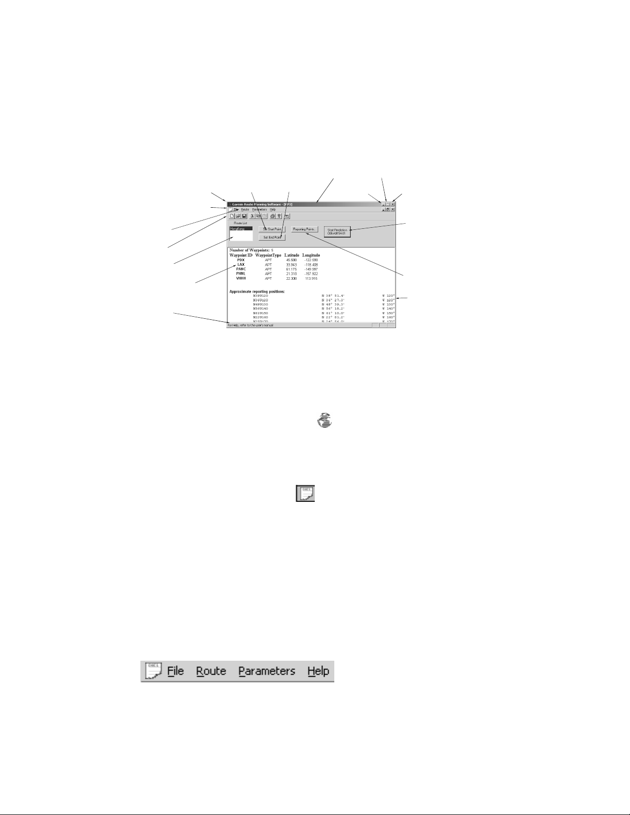
Application Window
The Garmin Route Planning application window is shown below.
Program Control-menu box
File Control-menu box
Menu Bar
Tool Bar
Route List
Route Waypoints
Status Bar
Set Start
Point
Set End
Program Title Bar
The Program Title Bar shows the title of the program and the name of the currently
open route file.
Program Control-Menu Box
Point
rogram Title Bar
Minimize
ze
Close
Start Prediction Button
Reporting Points Button
Reporting Points Position
Click on the Program Control-Menu box to display a menu of commands you
can use to manipulate the Garmin Route Planning program window. To open the
Control menu, click on the Logo to the left side of the Program Title bar.
File Control-Menu Box
Click on the File Control-Menu box to display a menu of commands you can
use to manipulate a file window. To open the Control menu, click on the page icon
on the left side of the Menu bar.
Maximize/Minimize Buttons
The Maximize and Minimize buttons are the two arrow buttons on the top right
corner of a window. Click on the Maximize button to enlarge a window to its
maximum size. Click on the Minimize button to reduce a window to an icon.
Menu Bar
The menu bar shows the list of functions available in Garmin Route Planning. Click
on the menu item with the mouse to view the functions available for each menu item.
3
Page 10
Garmin Route Planning
The available functions on the Menu Bar are: File, Route, Oceanic, Parameters, and
Help. A full description of each function is given in the Reference section of this
guide.
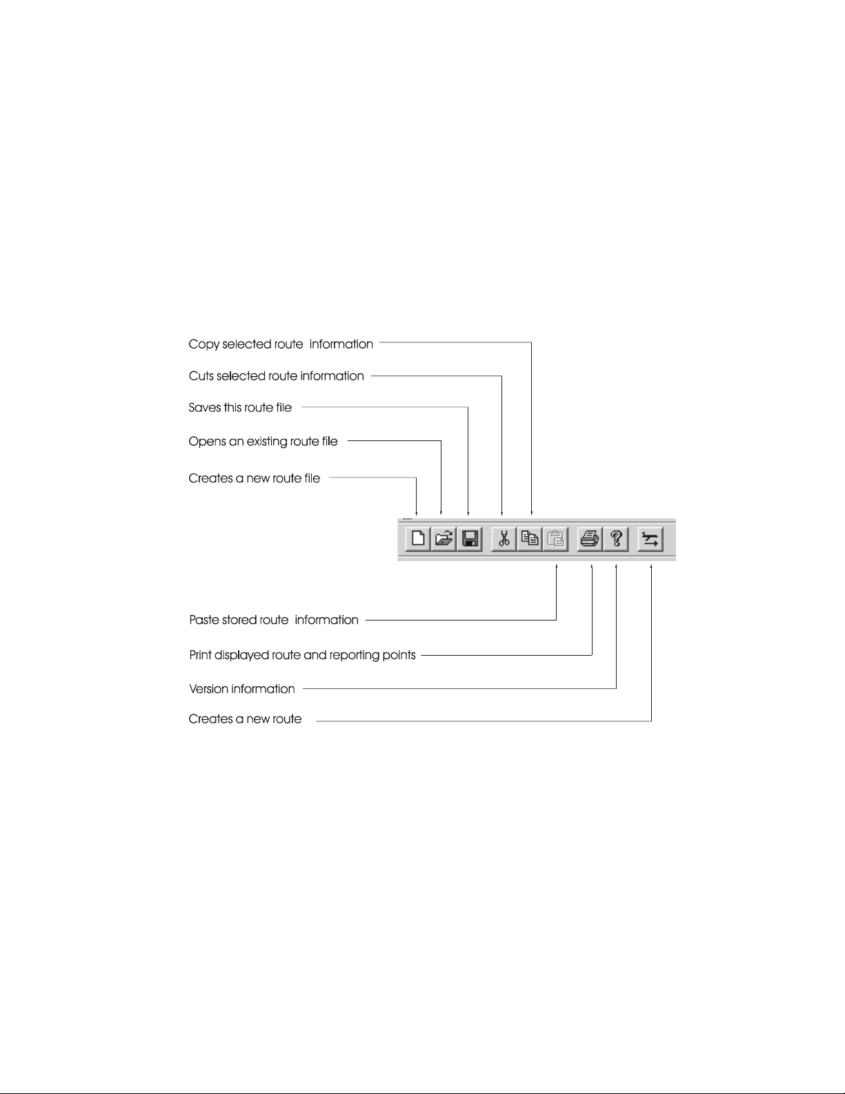
Tool Bar
The toolbar provides shortcuts to the most used functions. While all functions are
available from the menu bar, the tool bar buttons provide quick access to important
functions.
Status Bar
The Status bar is located at the bottom of the Garmin Route Planning window. The
Status Bar displays a description of the action the currently highlighted tool bar
selection will perform. Click and hold the left mouse button to view the description.
4
Page 11

Garmin Route Planning
Typical Order of Operations
The following steps are typical when using the Garmin Route Planning program.
• Start program
• Obtain a Navigation Database file (included)
• Select your Navigation Database file (see page 19)
• Define or edit a Route (see page 14)
• Set Start and End Points (see page 17)
• Start Prediction program (see page 19)
• Set Departure Date and Time (see page 27)
• Perform Flight Setup, (see page 28)
• De-select (Exclude) Satellites (see page 29)
• Enter average Ground Speed (see page 28)
• Calculate FDE Prediction (see page 31)
• Review the Prediction Results (see page 32)
Obtaining a Navigation Database
The Navigation database is an aid in creating routes. This database file contains
world-wide information on airports (with runways longer than 5,000 feet), VORs,
NDBs, and Intersections. The database is included on the disk with the program. A
Nav database is not required, but does simplify the creation of routes. If a database
is not available or the desired waypoints are not included in the database, waypoints
must be the “USER” type. You then must specify the waypoint name, latitude, and
longitude.
5
Page 12
Garmin Route Planning
Garmin Route Planning Menus
This section provides detailed information on the functions available with Garmin
Route Planning.
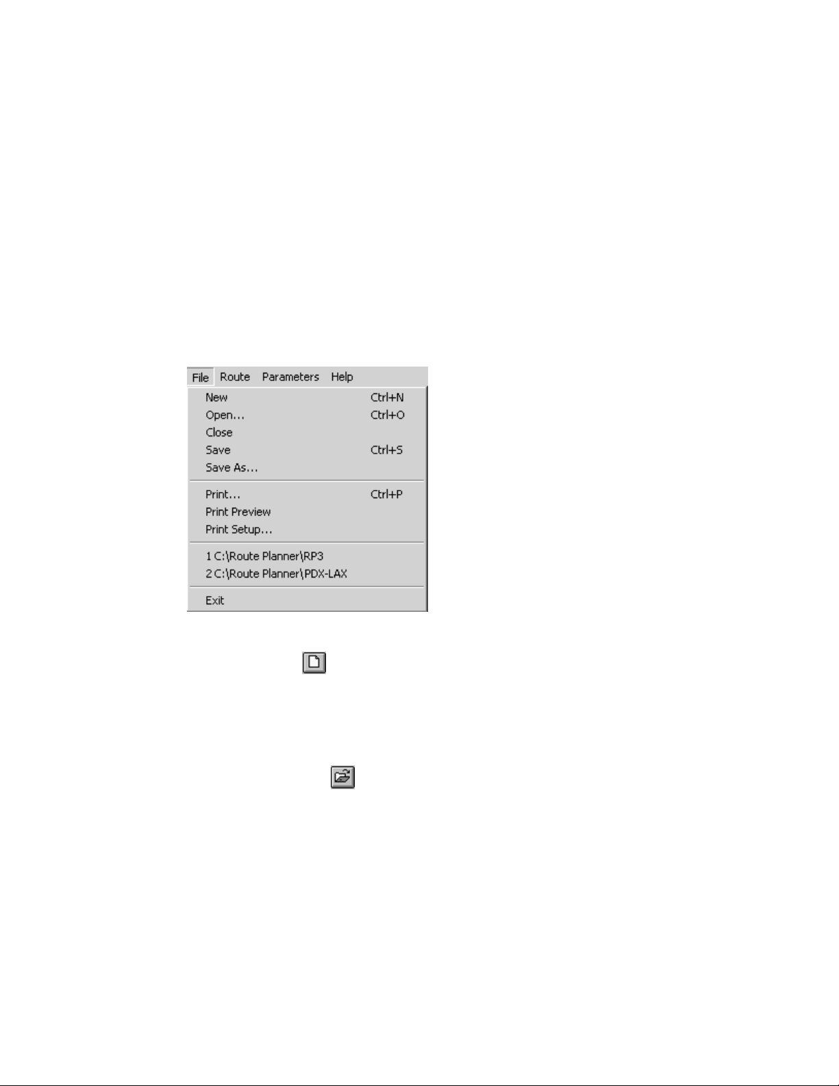
File Menu
The File menu is where you perform the file operations for Garmin Route Planning.
You can create a new route, edit an existing route file, add routes to an existing file,
open an existing file, save a file, rename a file, print prediction results, preview
printed results, setup a printer, select a recently used route, and exit the program.
New
The New menu item creates a new file.
1. Click on File.
2. Click on New.
3. Start adding routes to your new file.
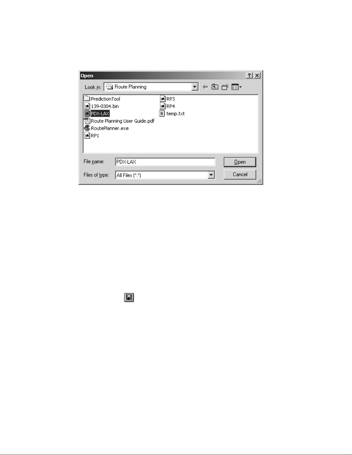
Open
Use the Open menu item to open a file that you have already created. You can
also use the Open icon on the toolbar. You may have multiple route files opened at
the same time.
6
Page 13
Garmin Route Planning
1. Click on File.
2. Click on Open.
3. Click on the “Look In” pull down list to select the drive and directory where you
store your projects.
4. Select the project with the mouse.
5. Click on the OK button or you can also double-click on a file name to quickly
load that file.
Close
Selecting the Close menu item will close, or exit, a file that you have opened. If you
have made any changes to the file, the program will ask you to save, not save, or
cancel the close action you have started and return to the main window.
Save
The Save selection will save the current file. You can also use the Save icon on
the toolbar.
1. Click on the File menu item.
2. Click on Save to save your displayed file. The same name and file location are
maintained.
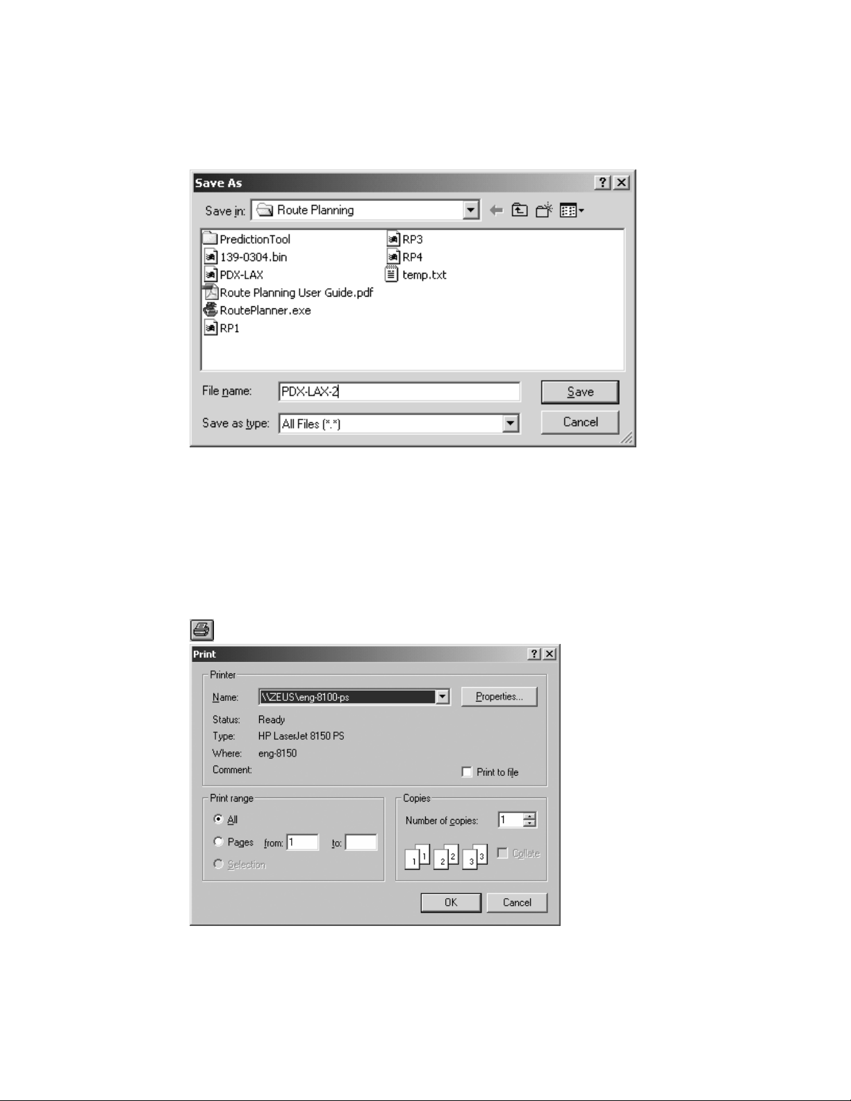
Save As
Saves the current file after you choose a new name or directory.
7
Page 14
Garmin Route Planning
1. Click on the File menu item on the Menu bar.
2. Click on Save As.
3. Choose a filename. Type a file name of up to eight characters and up to a three
letter extension. The default is no extension.
4. Choose the folder or directory where you want to store your file.
5. Click on OK when you have finished your choices.
Print
Print the current route and any reporting points. You may also use the Printer icon
.
8
Page 15
Garmin Route Planning
1. Click on the File menu item on the Menu bar.
2. Click on Print. Click on OK to print your route and any reporting points, or
continue with the following steps for more detailed actions.
3. Select one of the Print range options: all or selected pages.
4. Select the desired Properties after pressing the Properties tab.
5. Select the number of copies to print.
6. Click on the OK button to print the file.
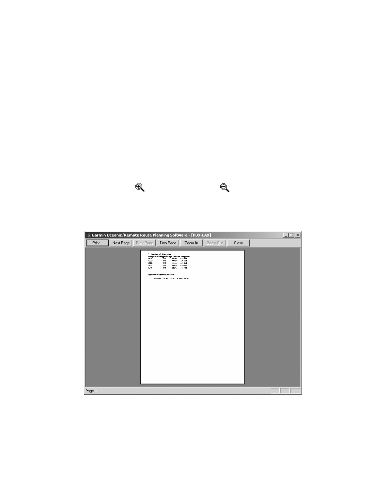
Print Preview
Display the current route prediction results as it would look when printed.
1. Click on the File menu item on the Menu bar.
2. Click on Print Preview. View your document as it will look if printed.
3. The cursor changes to a magnifying glass when it is over the document area. Click
once to zoom in
and click again to zoom out .
4. Buttons are available at the top of the window. Press Print to print the report
immediately. Click on Next or Previous Page to navigate through your report.
Click on Two Page to display two pages side by side. Click on Zoom In or Out
to change magnification. Click on Close to return to the main program window.
9
Page 16

Garmin Route Planning
Print Setup
Setup your printer as you would like your printouts to be formatted.
1. Click on the File menu item on the Menu bar.
2. Click on the Print Properties selection to access the options available for your
printer.
Last Used Routes
The names of the last routes (up to four) that were saved are displayed at the bottom
of the File menu. Click on the route name to instantly open it.
Exit
This selection exits the program. You will be asked to save your route files, if you
have not already done so. You may also double-click on the Control-menu box to
close the program. Click on the X at the top right of the screen to exit the program.
Route Menu
The Route function allows you to manage the routes that are contained within a
route file. Each route is named and contains a series of waypoints. The waypoints in
the route are defined by a type, ID, and Lat/Lon. After creating a route, you can add,
insert, change, or delete the waypoints in the route.
Undo
This selection undoes the last action.
1. Click on the Route menu item on the Menu bar.
2. Click on the Undo selection to undo the last action. If Undo is grayed, there is
no action to Undo.
10
Page 17

Garmin Route Planning
Redo
This selection repeats the last action that was “undone.”
1. Click on the Route menu item on the Menu bar.
2. Click on the Redo selection to Redo the selection. If Redo is grayed, there is no
action to Redo.
New
The New selection creates a new route in the current route file. You may also click
on the New Route icon on the Toolbar.
1. Click on the Route menu item on the Menu bar.
2. Click on the New selection to create a new Route.
Edit
The Edit selection allows you to modify the selected route in the Route file. Doubleclicking on a route name will also take you to the Route Information screen for
editing.
1. Use the mouse to highlight the route you want to edit. Double-clicking on the
route name takes you to the Route Information screen.
2. Click on the Route menu item on the Menu bar.
3. Click on the Edit selection to edit the Route.
Cut
The Cut selection deletes the selected route and places it into the clipboard.
1. Use the mouse to highlight the route you want to Cut.
2. Click on the Route menu item on the Menu bar.
3. Click on the Cut selection to cut the route and place it in the clipboard.
Copy
1. Click on the Copy selection to copy the highlighted route.
2. Use the mouse to highlight the route you want to copy.
3. Click on the Route menu item on the Menu bar.
4. Click on the Copy selection to copy the selected route into the clipboard.
11
Page 18

Garmin Route Planning
Paste
Click on the Paste selection to insert a copied or cut route from the clipboard
into another route file.
1. Place the cursor where you want to paste the route from the clipboard.
2. Click on the Route menu item on the Menu bar.
3. Click on the Paste selection to paste the route from the clipboard.
Delete
Click on the Delete selection to delete the selected route without saving the route to
the clipboard.
1. Use the mouse to select the route you want to delete.
2. Click on the Route menu item on the Menu bar.
3. Click on the Delete selection to delete the route.
Transfer Routes Between Route Files
You may transfer routes between route files by one of the following methods:
1. Copy the Route file to a new file name.
2. Open a Route file and use the Save As function to save it as a new file name.
3. Cut or Copy a route from one file, open a different file, and then paste the route
into the file.
12
Page 19

Garmin Route Planning
R
e
Main Application Window Details
The following information provides detailed information about the parts of the Main
application window.
Route List
The Route List contains the list of routes that are saved in the displayed Garmin
Route Planning file. Clicking on a route in the Route List will display the waypoints
and data selected for that route. You may double-click on the desired route in the
Route List to edit the route information.
Route Data
The Route Data shown on the main program screen reflects the information
specified for the selected route along with estimated reporting positions. The Route
Data is not editable on this display, but may be changed for each route by selecting
that route, then selecting Edit from the Route menu item or double-clicking on the
desired route in the Route List.
oute Nam
Route List
Number of Waypoints
in Route
Route Waypoints
Positions of Reporting Points
13
Page 20

Garmin Route Planning
Defining a Route
The Route Information window is displayed when you select the Route-New menu
selection, double-click on a route name, double-click on a route’s waypoint, or click
on the New Route toolbar icon.
This window presents the data entry fields required to define the route for the
prediction calculations. The fields will contain route information if a route was
selected for editing. The route name and waypoint information will be blank for a
new route.
Use the TAB, Up arrow, and Down arrow keys to move from one screen field to
another. The combination of SHIFT-TAB moves the cursor in the reverse direction.
Up to 256 waypoints may be specified per route.
Clicking on the OK button accepts the route as specified. Clicking on the Cancel
button disregards any modifications made since this screen was displayed and
returns control to the main application window.
14
Page 21

Garmin Route Planning
Route Name
You may specify a route name when you create a route or edit the route name of an
existing route. Changing the route name does not create a new route with the new
name. Route names are limited to nine characters.
Route Waypoints
The list is in the order of use and includes the identifier and Lat/Lon position. The
waypoint window will permit scrolling when the number of waypoints exceeds the
space available.
Waypoint Type and ID
Enter route waypoints by type and ident. If a database is being used, pressing the
TAB key after specifying an airport, VOR, NDB, or intersection ident causes the
program to extract the latitude and longitude coordinates for the given ident and
type and populate the latitude and longitude fields. You are not permitted to modify
latitude and longitude coordinates of waypoints in the database. If multiple
waypoints have the same ident, the program will display a Select Waypoint window
so you can select the correct waypoint for your route. Waypoint IDs are limited to
six characters.
NOTE: If a Waypoint Type other than “User” is selected and the
specified ident is not in the database file, the program will change
the type to “User.” The program will also determine if a User
waypoint with the same ident has already been defined. If there is
an existing User waypoint with that ident, the coordinates for the
waypoint will be retrieved. If there is no User waypoint by that
ident, the coordinates will be set to N 0’0.0” E 0’ 0.0”.
Waypoint Lat/Lon
The Latitude and Longitude coordinates for the waypoint used in the route. When
the hemisphere identifiers (N, S, E, W) are highlighted, the Enter key toggles
between the two selections for that hemisphere (N or S, E or W).
Specify user-defined waypoints by selecting the “user” type and entering an ident.
Pressing the TAB key after specifying a user waypoint ident will cause the program
to fill the latitude and longitude fields with the coordinates retrieved from the user
waypoint file. You may modify the coordinates of user waypoints. If the program
can not find a matching ident, the program assigns coordinates of 0 degrees latitude
and 0 degrees longitude.
Add Waypoint
The Add waypoint button inserts the waypoint at the end of the route.
15
Page 22

Garmin Route Planning
Insert Waypoint
The Insert Waypoint button inserts the new waypoint above the selected waypoint.
Change Waypoint
The Change Waypoint button changes the waypoint information to match the
information in the waypoint edit fields.
Delete Waypoint
The Delete Waypoint button deletes the selected waypoint record and “moves”
subsequent waypoint records up.
Select Waypoint Window
The following window is displayed when multiple waypoints have the same
identifier, user waypoints excluded. The window may be scrolled when the number
of waypoints exceeds the amount that can be displayed in a single window. The
following information is available in the Select Waypoint window for each of the
idents:
1. Ident
2. Ident/Facility name
3. Country
4. Latitude/Longitude coordinate
You can then select the desired waypoint by highlighting the waypoint or moving
the highlight bar with the Up/Down arrow keys. Then, click on OK with the mouse
or press the Enter key.
16
Page 23

Garmin Route Planning
Setting Start and End Points (Oceanic)
The Set Start and End Points selections allow you to select the starting and ending
waypoints that define the Oceanic/Remote portion of the flight. The launch status for
Oceanic/Remote flights are made on the portion of the flight that is bound by the
Start and the End waypoints.
NOTE: For prediction purposes only, the waypoints that define
the Oceanic/Remote portions of the flight must be entered into
the route. Other waypoints may be specified, but are not required
for the prediction functions.
Set Start Point
Select the starting waypoint for the portion of the flight plan that begins the
Oceanic/Remote flight phase. More waypoints may exist in the flight plan that
precede this waypoint over land. The default is the first waypoint in the route. You
must already have created the route before selecting the starting waypoint.
1. Click on the Set Start Point button on the main program page.
2. The route waypoint list will be displayed. Click on the waypoint where the
Oceanic/Remote phase begins to highlight it.
17
Page 24

Garmin Route Planning
3. Click on OK.
Set End Point
Select the ending waypoint for the portion of the flight plan that ends the
Oceanic/Remote phase. More waypoints may exist in the flight plan that continue
over land. The default is the last waypoint in the route. You must have already
created the route before selecting the end waypoint.
1. Click on the Set End Point button on the main program page.
2. The route waypoint list beyond the start waypoint will be displayed. Click on
the waypoint where the Oceanic/Remote phase ends to highlight it.
3. Click on OK.
18
Page 25

Garmin Route Planning
Start Prediction
The Start Prediction button will begin the Oceanic/Remote prediction calculations
for the selected route.
1. Click on the Start Prediction button on the main program page.
2. The prediction program will .
Parameters Menu
The Parameters Menu item allows you to select a database or locate the prediction
program. Locating the prediction program only needs to be done the first time this
program is used.
Nav Database
The Navigation Database is a library of waypoint information used for entering
waypoints into a route. When a database is not used, waypoints must be entered
manually. You only need to select the Nav Database: the first time that you use the
Garmin Route Planning program, if the database file name changes, or the database
file location changes. The use of a database is optional. A database file is included
with the Garmin Route Planning program.
19
Page 26

Garmin Route Planning
Help Menu
Version information for Garmin Route Planning is accessed by clicking on the Help
menu.
About...
1. Click on Help.
2. Click on “About...”. Version information is provided about Garmin Route
Planning.
20
Page 27

Garmin Route Planning
Reporting Points
Clicking on the Reporting Points button causes the screen shown below to be
displayed with the route name and calculated reporting points for the route.
Reporting points are defined as the latitude (and longitude) at each 10 degree
longitude increment around the globe along the proposed flight. Reporting points are
assigned names that are generated by appending the longitude hemisphere and
degree to the latitude hemisphere and degree (i.e. N39W120).
The Garmin Route planning program determines the latitude for each 10 degree
longitude increment and presents the reporting point name, latitude, and longitude as
shown below. This information is also available on the main application window
below the route waypoints.
21
Page 28

Garmin Route Planning
FDE Prediction
WAAS RAIM/FDE Prediction Program instructions
NOTE: These instructions assume the user has experience
operating the G1000 with GIA 63W, the GNS480, or the applicable
GNS 400W/500W Series Unit and is familiar with the operation of
RAIM and FDE.
Fault Detection and Exclusion (FDE)
The GARMIN G1000 with GIA 63W, the GNS480, and the GNS 400W/500W
Series products incorporate Fault Detection and Exclusion (FDE) features, satisfying
the requirements of TSO-C145a, TSO-C146a, and “GPS Oceanic/Remote
Navigation” per FAA AC 20-138A Appendix 1.
FDE consists of two distinct parts: fault detection and fault exclusion. Fault
detection (RAIM) detects the presence of an unacceptably large pseudorange error
(and presumably, position error) for a given mode of flight. Fault detection is
synonymous with RAIM (Receiver Autonomous Integrity Monitoring). Upon the
detection of a fault, fault exclusion follows and excludes the source of the
unacceptably large pseudorange error, thereby allowing navigation to return to
normal performance without an interruption in service. FDE functionality is
provided for oceanic, en route, terminal, and non-precision approach phases of
flight. The FDE functionality adheres to the missed alert probability, false alert
probability, and failed exclusion probability specified by TSO-C145a/146a.
The WFDE Prediction Program (006-A0154-01, 006-A0154-02, and 006-A0154-
03) is designed for use with TSO-C145a/TSO-C146a approved, WAAS-(Wide Area
Augmentation System) certified Garmin products. These products include:
• GPS 400W, GNC 420W, GNC 420AW, GNS 430W, GNS 430AW
• GPS 500W, GPS 500W TAWS, GNS 530W, GNS 530W TAWS, GNS
530AW, GNS 530AW TAWS
• GNS 480
• G1000 with GIA 63W
Pre-Departure Verification of RAIM/FDE
A RAIM or FDE prediction must be performed prior to departure for the following
types of flight plans:
22
Page 29

Garmin Route Planning
• An FDE prediction is required for Oceanic/Remote operation where GPS is
to be the primary source of navigation per FAA AC 20-138A Appendix 1.
• A RAIM prediction is required for all other flight operations in accordance
with local aviation authority guidelines for TSO-C129a equipment, as
required by an Aircraft Flight Manual limitation placed on Garmin G1000
with GIA 63W, GNS 480, and GNS 400W/500W Series products. Examples
of such operations include navigation of U.S. Area Navigation (RNAV)
routes, Standard Instrument Departures (SIDs), or Standard Terminal Arrival
Routes (STARs) per FAA AC 90-100 “U.S. Terminal and En Route Area
Navigation (RNAV) Operations”.
• A WAAS satellite visibility prediction is required for all LVAV/VNAV or
LPV approach as required by an Aircraft Flight Manual limitation placed on
Garmin G1000 with GIA 63W, GNS 480, and GNS 400W/500W Series
products.
Prior to departure, the operator must use the WFDE Prediction Program supplied
with the applicable trainer or route planning software to demonstrate that there are
no outages in the capability to navigate on the specified route of flight. The WFDE
Prediction Program determines whether the GPS constellation is robust enough to
provide a navigation solution for the specified route of flight.
Running the FDE Prediction Program
Trainer and route planning software for WAAS-certified Garmin products include a
WFDE Prediction Program to meet the FDE requirements for GPS as a primary
means of navigation for Oceanic/Remote operations (reference FAA AC 20-138A
Appendix 1). The Oceanic/Remote flight phase occurs when the flight plan will
place the aircraft more than 200 nautical miles from the nearest airport. All
operators using a Garmin WAAS-certified unit as primary means of navigation in
oceanic/remote areas under FAR parts 91, 121, 125 and 135 must utilize the WFDE
Prediction Program prior to conducting a flight in these areas.
Prior to navigation on U.S. RNAV routes, SIDs, and STARs (reference FAA AC
90-100) all operators of Garmin WAAS-certified units must utilize the WFDE
Prediction Program to determine RAIM availability.
All operators of Garmin WAAS-certified units should utilize the WFDE Prediction
Program to determine WAAS satellite visibility when planning an LNAV/VNAV or
LPV approach.
The detection function (of Fault Detection and Exclusion) refers to the ability to
detect a satellite failure which can affect navigation. The exclusion function refers to
the ability to exclude one or more failed satellites and prevent them from affecting
23
Page 30

Garmin Route Planning
navigation. The WFDE Prediction Program allows the pilot to specify the planned
departure date/time, route type, ground speed, ground speed variation, and
maximum allowable outage. When provided through NOTAM or other sources,
GPS satellites with known failures can be excluded through the program's setup
function.
To use the WFDE Prediction Program, begin by entering the intended flight plan
into the applicable trainer software (G1000 Trainer or GNS 400W/500W Trainer) or
the Garmin Route Planning software for the GNS 480. The WFDE Prediction
Program uses this information to analyze satellite coverage along the intended route
of flight.
NOTE: A flight plan must be created and activated (using the
Route Planning software) prior to running the WFDE Prediction
Program. The WFDE Prediction Program only works with the
currently active flight plan. Follow the software instructions to create
and activate a flight plan. Software and instructions are available via
the Garmin website at www.garmin.com
.
Start FDE Prediction
1) Make sure the Route Planning software is running and the desired flight plan
is active.
2) Click on the ‘Start Prediction’ button after setting up the route (Figure 1).
Figure 1 Start Prediction Program Options
NOTE: If the WFDE Prediction Program has not been used
previously, or has not been run recently, a series of pop-up
messages (Figure 2) may precede the WFDE Prediction Program
window. Follow the on-screen instructions to download new data
from the internet. The download time is normally very short (nearly
instantaneous), but may vary with internet connection. See the
‘Updating/Changing the Almanac and Configuration Files’ section of
this document for details.
24
Page 31

Garmin Route Planning
Figure 2 Possible Update Messages
4) The WFDE Prediction Program window appears (Figure 3) listing the flight
plan waypoints, selected antenna, and the current date/time as the departure
time. It is important to verify that the displayed route is correct before
proceeding with the prediction. Reference Table 1, and verify the correct
Garmin part number (006-A0154-0X) appears at the top of the screen. If the
part number is incorrect, see the ‘Configuration Files’ section of this
document.
NOTE: If the route of flight requires an alternate airport, multiple
predictions may be required (one for the primary and one for the
alternate) to verify RAIM and/or WAAS satellite visibility availability
at the primary and the alternate approach.
25
Page 32

Garmin Route Planning
Figure 3 WFDE Prediction Window
Select Antenna
Make sure that the selected antenna matches the antenna installed on the aircraft that
will fly the flight plan. To change the selected antenna, click the down arrow next to
the ‘Antenna’ field. A pull-down list appears listing the available antennas. If the
correct antenna is not known, select ‘Most Conservative’ for the most restrictive
mask angle of the antenna options.
26
Page 33

Garmin Route Planning
Figure 4 Antenna Pull-Down List
Set Departure Date
To change the departure date, click the down arrow next to the ‘Date (UTC)’ field.
A calendar window appears. Click the left or right arrows to select a different month
(if desired), then click the desired date. The departure date can also be changed in
the Flight Setup window.
Set Departure Time
To change the departure time, click the hours, minutes, or seconds fields next to the
‘Time (UTC)’ field. Click the up or down arrows (or type in desired time) to change
the displayed time. The departure time can also be changed in the Flight Setup
window.
27
Page 34

Garmin Route Planning
Flight Setup
To change the planned route type, average ground speed, ground speed variation,
maximum allowed outage, flight duration, Selective Availability conditions, or to
deselect satellites, click the ‘Setup’ button. A setup window is displayed (Figure 5).
Click the field for the desired item, then enter the desired value. Table 2 describes
the Flight Setup Window options.
Flight Setup Window Options
Route Type Oceanic -For Oceanic/Remote only operations.
En route/Terminal - For all other operations.
Maximum
Allowed Outage
(Time)
Ground Speed
This field defaults to 5 minutes when Oceanic is the selected
route type. This field is set to default and ‘greyed out’ (not
selectable) when En route/Terminal is the selected route type.
Enter expected average ground speed for flight.
(Avg)
Ground Speed
Variation
The ground speed variation setting will vary with the selected
route type. The default is 100 knots for Oceanic and 10 knots
for En route/Terminal route types. The program automatically
runs multiple predictions for a range of ground speeds based
on this setting.
Flight Duration This field is calculated from the entered ground speed and
route information; or the flight duration can be entered, and the
program will calculate the average ground speed.
Departure Date
and Time
Selective
Availability
Enter date and time (in UTC format) of departure, this info can
also be entered into the main screen of this program.
Simulates Selective Availability conditions when box is checked
(normally left unchecked).
De-select
Satellites
28
Click on the De-select Satellites button to view the Selected
Satellites window, see following instructions.
Table 2
Page 35

Garmin Route Planning
NOTE: The maximum allowed outage time for Oceanic flights vary
according to the specific route. The pilot must determine the proper
allowed outage time to be used for the prediction.
Figure 5 Flight Setup Window
Deselect Satellites
To deselect satellites from the setup window, click ‘De-select Satellites’, then clear
the box adjacent to any satellite that should not be used in the prediction (Figure 6).
WAAS satellites are not listed in the Selected Satellites Window. Always check for
NOTAMs (regarding satellite availability) as well as using the Prediction Program
to ensure Approach availability at the destination.
29
Page 36

Garmin Route Planning
Figure 6 Selected Satellites Window
NOTE: Satellites that are unavailable will be ‘greyed-out’ with no
check marks. Satellites with ‘Poor Health’ will default to unchecked
status.
30
Figure 7 Almanac Warning
Page 37

Garmin Route Planning
NOTE: To ensure accuracy of results, the almanac data used for
the RAIM and FDE predictions must be recent. If the information is
out of date, the WFDE Prediction Program will automatically prompt
the user to update the almanac data (Figure 7). An internet
connection is required to use this feature (see following
instructions).
Calculate FDE Prediction
1) To calculate RAIM, FDE availability, and WAAS satellite availability; select
the ‘Calculate’ button from the main WFDE Prediction Program window
(Figure 3). A ‘Calculation is complete’ message will appear when the
prediction is complete (Figure 8).
Figure 8 Calculations Complete Screen
2) The GPS/FDE Availability Results screen (Figure 9) appears after clicking
the OK button on the ‘Calculation is complete’ message screen. The results
can be viewed or printed for later reference.
31
Page 38

Garmin Route Planning
GPS Prediction
Results
RAIM Prediction
Results
FDE Prediction
Results
Displays the
Maximum FDE
Outage Only (May
Be Other FDE
Outages)
This Prediction
is Base d On
the Displayed
Estimated Arrival
Time ±15 Min.
ETA Calculation
Uses Ground Speed
(Not Ground Speed
Variation)
Setup Information Box
Displays the Leg
of Route Where
Outage Occurs
Ground Speed For Outage
May Differ From Enter ed
Ground Speed, as Multiple
Predictions are Calcul ated,
Based on Entered Ground
Displays the Results
of the WAAS Satellite
Availability Prediction
Figure 9 GPS/FDE Availability Results Screen
Viewing the RAIM and FDE Prediction Results
1) Select the View menu from the main WFDE Prediction Program window.
The results also appear automatically after clicking the OK button on the
‘Calculation is complete’ message screen.
2) Select Results. A window will appear showing the calculation results
(Figure 9).
3) To print the calculation results, click the Print button.
Speed Variation
Printing the RAIM and FDE Prediction Results
1) Press the Print button in the lower right section of the display.
Or
1) While the Prediction Results page is open and selected (the title bar is
highlighted). On your keyboard, press and hold the Alt key and then press
the Print-Screen key. This copies the Prediction Results page.
2) Open an application such as Word, Paint, etc.
3) Paste the copied page into the application by pressing the Ctrl and V keys at
the same time.
4) Print the page with the pasted information. You may need to change the
page orientation to Landscape to print on a single sheet of paper.
32
Page 39

Garmin Route Planning
Interpreting the FDE Prediction Results
The GPS/FDE Availability Results screen provides either a ‘GO’ or ‘STOP’ status
for the GPS, RAIM, FDE, LNAV RAIM, and LNAV/VNAV & LPV minima
availability. A yellow flag is a possible result for an FDE prediction for a nonOceanic prediction. (see Figure 10)
A ‘GO’ status indicates that there are enough satellites available during the flight to
meet the requirements of that category.It is possible to have multiple FDE
Availability outages during the flight and the status may still be a ‘GO’, as long as
none of the outages exceeds the selected maximum allowable outage.
Figure 10 Prediction Results Icons
A ‘STOP’ status is the result of a predicted loss of satellite availability. An FDE
Availability or RAIM availability failure occurs when sufficient satellites are not
available for a period longer than the maximum allowable outage (as selected in the
Flight Setup page and viewed in the Setup Information box on the GPS/FDE
Availability Results screen) and will produce a ‘STOP’ status.
A yellow flag indicates an FDE outage in a non-Oceanic (Enroute/Terminal) type
prediction. Because FDE availability is not required for Enroute/Terminal
operations the yellow flag is only a caution to the pilot indicating that there may be
an FDE outage when flying the flight plan. The selected flight plan may be flown
despite the caution flag. A ‘STOP’ status can appear in the FDE outage section only
when an Oceanic prediction results in an FDE outage.
More satellites are needed to provide FDE availability than are needed for RAIM.
More satellites are needed to provide RAIM availability than are needed for basic
GPS availibilty. A GPS Availability failure occurs when there is the loss of the
ability to compute a position. This is expected to be accompanied by a an FDE
availability failure and a RAIM availability failure.
• For Oceanic/Remote navigation predictions the displayed result should be
‘FDE is available for this route’. In the event of a predicted outage, the flight
should be delayed, canceled, or re-routed where FDE requirements can be
met.
• For U.S. RNAV routes, SIDs, or STARs navigation predictions, the displayed
result should be ‘RAIM is available for this route’. In the event of a
predicted outage, the flight should be delayed, canceled, or re-routed where
RAIM requirements can be met.
33
Page 40

Garmin Route Planning
• For LNAV approach at the arrival waypoint predictions, the displayed result
should be ‘LNAV RAIM is available’. In the event that LNAV RAIM is not
available, flight planning should include an approach that is not based on
GPS navigation equipment.
• For LNAV/VNAV or LPV approach at the arrival waypoint predictions, the
displayed result should be ‘LNAV/VNAV & LPV minima may be used for
flight planning at the arrival waypoint for the estimated arrival time’. In the
event of an ‘LNAV/VNAV & LPV minima should not be used for flight
planning at the arrival waypoint for the estimated arrival time’ result, flight
planning should include an approach that has at least LNAV minima (if based
on GPS navigation equipment) or an approach that is not based on GPS
navigation equipment.
NOTE: Since (due to unforeseen circumstances) actual departure
times often differ from planned departure times, it is good practice to
perform predictions for several possible departure times.
Suggestions to change the result of a failed flight plan
prediction:
1) Alter the departure date and time.
2) Alter the route of flight.
3) Verify any deselected satellites. It is possible that some satellites unavailable
for a previous prediction are now available.
4) Update the almanac, especially if it is more than three months old.
5) Use the correct antenna selection (if ‘Most Conservative’ was used).
6) For Oceanic/Remote operations, determine the actual maximum allowed
outage and use for the prediction (instead of the 5 minute default setting
which is generally shorter than the actual allowed outage time).
Updating/Changing Almanac and Configuration Files
Almanac, GEO Almanac, and Configuration Files
To ensure that each is current, the Almanac, GEO Almanac, and Configuration Files
are automatically checked each time the program is started. If the program finds any
of these files to be out of date, it will automatically update the file via the internet.
A provision has been made to update these files manually, if needed.
34
Page 41

Garmin Route Planning
Manually updating the Almanac, GEO Almanac, and Configuration
files:
1) From the main WFDE Prediction Program window, select the Help menu
(Figure 11).
Figure 11 Help Pull-Down Menu
2) Select Update Almanac, Update GEO Almanac, or Update Configuration
File. The program automatically searches the internet and downloads the
most recent data.
3) A pop-up window appears to confirm that the data has been downloaded.
Click the OK button to return to the WFDE Prediction Program.
4) The file has been updated.
Configuration Files
The WFDE Prediction Program may be used with several different Garmin software
programs. Each program uses a specific configuration file to run the WFDE
Prediction Program. If the user has multiple Garmin programs loaded, the user must
verify that the configuration file currently in use is correct for the Garmin product
that will be used to navigate the flight plan. Generally speaking, most users will not
need to change the configuration file, although a provision has been made to update
these files manually, if needed.
35
Page 42

Garmin Route Planning
Changing the WFDE Configuration File:
1) From the main WFDE Prediction Program window, select the Help menu
(Figure 11).
2) Select ‘Change WFDE Configuration File’.
3) A pop-up window appears. Click the OK button to allow the program to
download new configuration files via the internet. When the configuration
files have been downloaded, a ‘Configuration Select’ pop-up window
appears.
4) Click the down arrow to view the pull-down list of available configuration
files (Figure 12). Select the file corresponding to the Garmin product that
will be used to navigate the flight plan.
Figure 12 Configuration Select Window
5) Click the correct file name on the pull-down list, then click the OK button.
6) The configuration has been changed. See Figure 3 and Table 1 to verify the
correct part number appears on the WFDE Prediction Program window
36
Page 43

Garmin Route Planning
Glossary of Navigation Terms
A
Azimuth: an arc, as measured clockwise from true or magnetic north.
B
Bearing (BRG): The direction to any point, usually measured in degrees relative to
true or magnetic north.
BIN: The file extension for a Garmin AT supplied binary database file.
C
Class II Airspace: Airspace that is out of the range of land-based navaids. Class II
airspace includes areas both remote (over land) and over water.
Constellation: A group of stars or objects, such as satellites, in the heavens.
Coordinates: Values for latitude and longitude that describe a geographical point
on the surface of the earth.
D
Database: A collection of data structured in such a way as to allow quick and
convenient access to any particular record or records.
Degree: 1/360th of a circle.
Departure: The first waypoint in the active route.
Departure Date: The date of departure for the flight as entered in the route file for
the purpose of calculating prediction results.
Departure Time: The time of departure for the flight as entered in the route file for
the purpose of calculating prediction results.
Destination: The last waypoint in the active route.
E
Elevation: The angle of a GPS satellite above the horizon.
Elevation Mask Angle: See Mask Angle.
Excluded Satellites: See Satellite Exclusion List.
37
Page 44

Garmin Route Planning
F
FDE: Fault Detection and Exclusion. A method to detect a satellite failure (via
RAIM algorithm), determine which satellite failed, exclude that satellite from the
position solution, the capability to determine that the correct satellite was excluded,
while still being able to detect any other satellite failure.
Fix: A geographical location determined by either visual reference or by electronic
navigation aids.
Flight Plan: A series of two or more waypoints.
G
Global Positioning System (GPS): Also known as NAVSTAR. A constellation of
satellites launched by the U.S. Department of Defense into six orbit lanes (four
satellites per plane) at an altitude of 10,898 nm above the earth.
Greenwich Mean Time (GMT): See Universal Time Coordinate (UTC).
Ground Speed (GS): Speed of travel across the ground. In aviation, the relation
between ground speed and air speed is affected by the prevailing winds. The
estimated ground speed for the Oceanic flight phase as entered in the route file for
the purpose of calculating prediction results.
H
HDOP: Horizontal Dilution of Precision. See Dilution Of Precision.
I
Identifier: A name, typically abbreviated, assigned to a waypoint. The identifier
may consist of numbers and alpha characters, up to six in length. For example, the
airport identifier for Los Angeles International Airport is LAX.
K
Knot (kt): A unit of speed equal to one nautical mile per hour.
L
Latitude (Lat): Any line circling the earth parallel to the equator, measured in
degrees, minutes, and seconds north and south of the equator.
Longitude (Lon): Any line from the North to the South Pole, measured in degrees,
minutes, and seconds of a circle, east or west of the Prime Meridian (Greenwich,
England).
38
Page 45

Garmin Route Planning
M
Magnetic North: The region, some distance from the geographic North Pole where
the earth’s magnetic lines concentrate. A magnetic compass points to the magnetic
north.
Mask Angle: The Mask Angle describes a cone looking up towards the GPS
satellites. The angle is the elevation in degrees above the horizontal plane below
which satellite signals will be ignored.
Meter (m): A metric distance measurement equal to 39.37 inches.
Minute: 1/60th of a degree.
N
Nautical Mile (nm): A distance measurement equal to 6,076 feet, or 1.15 statute
mile. One nautical mile is also equal to one minute of latitude.
Nav Database: a Garmin AT supplied binary database file. The Nav database is not
supplied with the Garmin Route Planning program. The Garmin Route Planning
database file is included on the product CD. Otherwise, you may call Customer
Technical Support.
NAVSTAR: The name given to GPS satellites formed from the acronym for
NAVigation System with Time And Ranging.
Non-Directional Beacon (NDB): A low frequency/medium frequency navigation
aid sending non-directional signals that can be used for navigation.
O
Oceanic Flight Phase: The portion of a flight that travels over water or a remote
region, that is beyond the range of terrestrial navaids (Class II airspace).
P
PDOP: Position Dilution of Precision. See Dilution of Precision.
R
RAIM: Receiver Autonomous Integrity Monitoring. A method of predicting
possible system accuracy errors that may be caused by bad satellite data. The RAIM
algorithm requires that more satellites are available and usable than required for a
normal GPS position fix.
Remote: Areas that are over land, but out of the range of land-based navaids.
Remote airspace is designated as Class II airspace.
39
Page 46

Garmin Route Planning
Reporting points: The latitude (and longitude) at each 10 degree longitude
increment around the globe along the proposed flight. Reporting points are assigned
names that are generated by appending the longitude hemisphere and degree to the
latitude hemisphere and degree (i.e. N34W40).
Route: The series of waypoints that embodies a flight plan from a departure to a
destination waypoint.
Route Name: The name of a route (collection of waypoints) within the Route file.
A number of routes may be contained within a single route file.
Route Spacing: The distance in nautical miles to adjacent tracks on either side of
the flight.
S
Second: 1/60th of a minute of a degree.
Statute Mile: A distance measurement equal to 5,280 feet or 0.87 of a nautical mile.
T
Three-dimensional (3D) Position Fix: A position fix defined by latitude, longitude,
and altitude.
Time Interval: The time interval between prediction checkpoints as shown in the
report file for the purpose of calculating prediction results.
Time of Prediction: The date and time when the prediction calculation is performed.
Time Zone: the time zone offset from UTC time.
U
Universal Time Coordinate (UTC): Greenwich Mean Time, or the time at the
Prime Meridian in Greenwich, England. Also referred to as Zulu time.
V
Very High Frequency Omnirange (VOR): Navigational aid that transmits signals such
that a receiver can indicate its current radial or bearing from the transmitter.
W
Waypoint: A navigation fix used in area navigation and defined by latitude and
longitude coordinates.
40
Page 47

Page 48

© 2006 Garmin Ltd. or its subsidiaries
Garmin International, Inc.
1200 East 151st Street, Olathe, Kansas 66062, U.S.A.
Garmin AT, Inc., 2345 Turner Rd., S.E., Salem, Oregon 97302, U.S.A.
Garmin (Europe) Ltd.
Unit 5, The Quadrangle, Abbey Park Industrial Estate, Romsey, SO51 9DL, U.K.
Garmin Corporation
No. 68, Jangshu 2nd Road, Shijr, Taipei County, Taiwan
www.garmin.com
560-0180-01 Rev A
November 2006
 Loading...