

Page 1
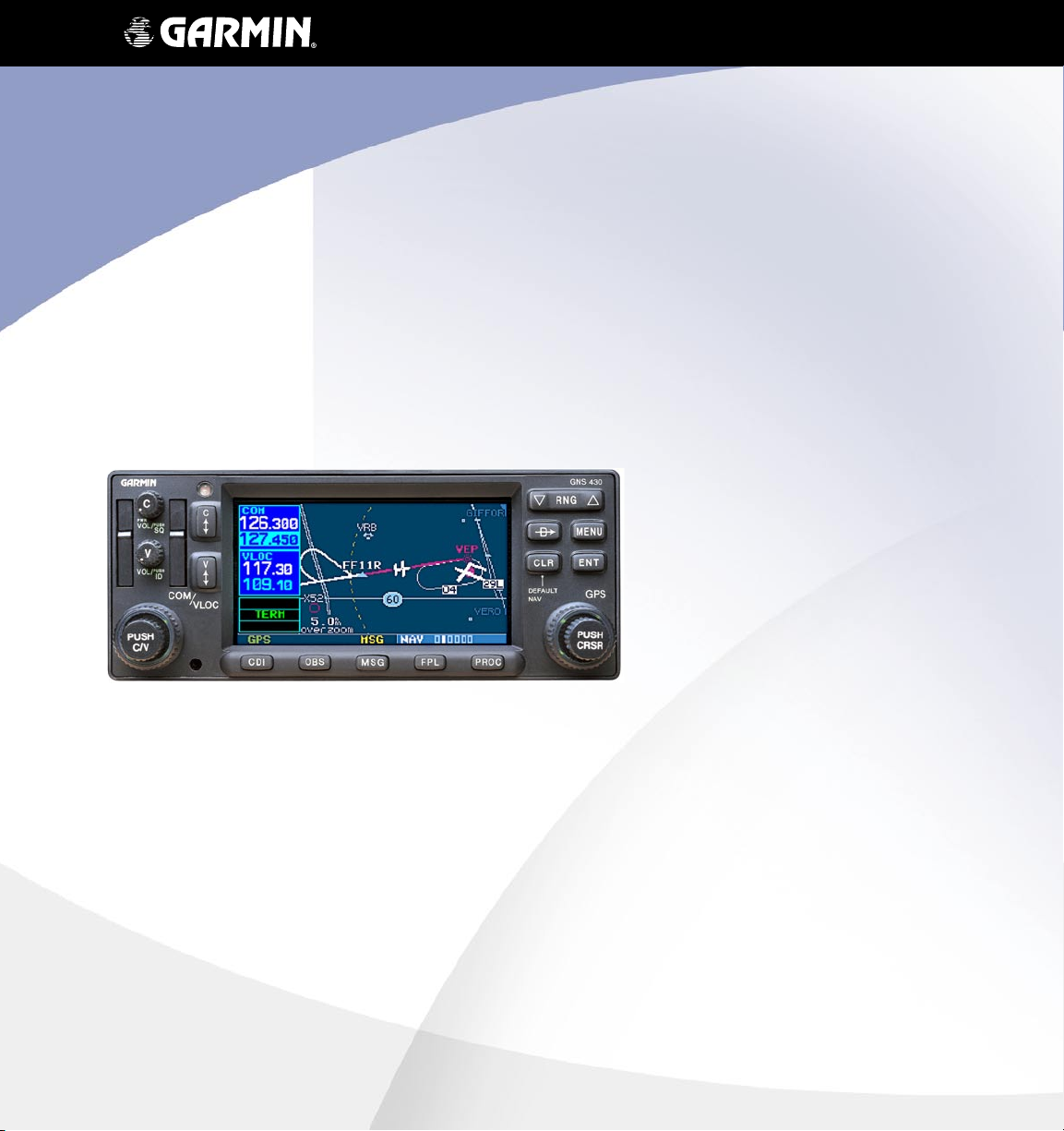
400W Series
Pilot’s Guide
& Reference
Page 2

Foreword
Foreword
Garmin International, Inc., 1200 East 151st Street, Olathe, Kansas 66062, U.S.A.
Tel: 913/397.8200 Fax: 913/397.8282
Garmin AT, Inc., 2345 Turner Rd., S.E., Salem, Oregon 97302, U.S.A.
Tel: 503/581.8101 Fax: 503/364.2138
Garmin (Europe) Ltd., Unit 5, The Quadrangle, Abbey Park, Romsey, Hampshire S051 9DL, U.K.
Tel: 44/0870.851241 (Europe) Fax: 44/1794.519222
Tel: 0808.2380000 (UK)
Garmin Corporation, No. 68, Jangshu 2nd Road, Shijr, Taipei County, Taiwan
Tel: 886/02.2642.9199 Fax: 886/02.2642.9099
Web Site Address: www.garmin.com
© 2006 Garmin Ltd. or its subsidiaries. All rights reserved. Except as expressly provided herein, no part of this
manual may be reproduced, copied, transmitted, disseminated, downloaded or stored in any storage medium,
for any purpose without the express written permission of Garmin. Garmin hereby grants permission to download a single copy of this manual and of any revision to this manual onto a hard drive or other electronic storage
medium to be viewed for personal use, provided that such electronic or printed copy of this manual or revision
must contain the complete text of this copyright notice and provided further that any unauthorized commercial
distribution of this manual or any revision hereto is strictly prohibited.
Information in this document is subject to change without notice. Garmin reserves the right to change or improve
their products and to make changes in the content of this material without obligation to notify any person or
organization of such changes or improvements.
October 2006 190-00356-00 Rev. A
Page 3
Cautions
Introduction
CAUTION: The Global Positioning System is operated
by the United States government, which is solely responsible for its accuracy and maintenance. The system
is subject to changes which could affect the accuracy
and performance of all GPS equipment. Although the
Garmin 400W-series are precision electronic NAVigation AIDs (NAVAID), any NAVAID can be misused or
misinterpreted and therefore become unsafe.
CAUTION: Use the
reduce the risk of unsafe operation, carefully review
and understand all aspects of this Owner’s Manual and
the Flight Manual Supplement, and thoroughly practice
basic operation prior to actual use. When in actual use,
carefully compare indications from the
all available navigation sources, including the information from other NAVAIDS, visual sightings, charts, etc. For
safety, always resolve any discrepancies before continuing navigation.
WARNING: The altitude calculated by the 400W-series
is geometric height above mean sea level and could
vary significantly from altitude displayed by pressure
altimeters in aircraft.
WARNING: The Jeppesen database incorporated in
the 400W-series must be updated regularly in order
to ensure that its information is current. Updates are
released every 28 days. A database information packet
is included in your 400W-series package. Pilots using
an out-of-date database do so entirely at their own
risk!
CAUTION: GPS receivers operate by receiving and
decoding very low power radio signals broadcast by
satellites. It is possible that in some situations other
radio equipment or electronic equipment used in close
proximity to a GPS receiver may create electromagnetic
interference (EMI) which may affect the ability of the
GPS receiver to receive and decode the satellite signals.
In such event, the interference may be reduced or
eliminated by switching off the source of interference
or moving the GPS receiver away from it.
400W-series
at your own risk. To
400W-series
to
INTRODUCTION
Cautions
CAUTION: The electronic chart is an aid to navigation and is designed to facilitate the use of authorized
government charts, not replace them. Land and water
data is provided only as a general reference to your
surroundings. The positional accuracy of the land and
water data is not of a precision suitable for use in
navigation and it should not be used for navigation.
Only official government charts and notices contain
all information needed for safe navigation – and, as
always, the user is responsible for their prudent use.
CAUTION: The Terrain feature is for supplemental
awareness only. The pilot/crew is responsible for all
terrain and obstacle avoidance using information not
provided by the 400W-series Terrain feature.
CAUTION: The Garmin 400W-series does not contain
any user-serviceable parts. Repairs should only
be made by an authorized Garmin service center.
Unauthorized repairs or modifications could void your
warranty and authority to operate this device under
FCC Part 15 regulations.
NOTE: The GNS 400W-series units use a different
database than in the legacy units. The databases are incompatible between units. The GNS 400W-series units
must use a WAAS enabled database.
NOTE: This product, its packaging, and its components
contain chemicals known to the State of California to
cause cancer, birth defects, or reproductive harm. This
notice is being provided in accordance with California’s
Proposition 65. If you have any questions or would like
additional information, please refer to our website at
www.garmin.com/prop65.
NOTE: It is the pilot’s responsibility for initial missed
approach guidance in accordance with published procedure. The unit may not provide correct guidance until
established on a defined leg.
i
Page 4

INTRODUCTION
Cautions
NOTE: This device complies with Part 15 of the FCC limits for
Class B digital devices. This equipment generates, uses, and
can radiate radio frequency energy and, if not installed and
used in accordance with the instructions, may cause harmful
interference to radio communications. Furthermore, there is
no guarantee that interference will not occur in a particular
installation.
If this equipment does cause harmful interference, the user is
encouraged to try to correct the interference by relocating the
equipment or connecting the equipment to a different circuit
than the affected equipment. Consult an authorized dealer or
other qualified avionics technician for additional help if these
remedies do not correct the problem.
Operation of this device is subject to the following conditions:
(1) This device may not cause harmful interference, and (2)
this device must accept any interference received, including
interference that may cause undesired operation.
Garmin is fully committed to your
satisfaction as a customer. If you
have any questions regarding the
400W-series, please contact our
customer service department at:
Help us better support you by completing our on-line registration form today! Registration ensures that you will be notified
of product updates and new products and provides lost or sto-
handy, connect to our web site (www.garmin.com) and look for
To obtain accessories for your 400W-series, please contact
your Garmin dealer.
len unit tracking. Please, have the serial number of your unit
our Product Registration link on the home page.
The 400W-series display lenses are coated with a special anti-
reflective coating which is very sensitive to skin oils, waxes
and abrasive cleaners. It is very important to clean the lens
using an eyeglass lens cleaner which is specified as safe for
anti-reflective coatings and a clean, lint-free cloth.
Garmin International, Inc.
1200 East 151st Street
Olathe, KS 66062-3426 U.S.A.
Phone: (913) 397-8200
Fax: (913) 397-8282
ii
Page 5

INTRODUCTION
Accessories and Packing List
Accessories and Packing List
Congratulations on choosing the world’s finest
panel-mounted IFR navigation/communication system!
The 400W-series represents Garmin’s continued commitment to providing you with the most advanced
technology available today — in an accurate, easy-touse design suitable for all of your flying needs.
Unless otherwise specified within this manual,
the term "
GNC 420W, GNC 420AW, GNS 430W, and GNS
430AW models. Please note that the difference
between these models is indicated in the Specifications section of this manual (see Appendix B).
400W-series
" applies to the GPS 400W,
Before installing and getting started with your new
system, please ensure that your package includes the
following items. If any parts are missing or are damaged, please contact your Garmin dealer.
Standard Package:
• Garmin 400W-series Unit
• NavData® Card
• Terrain Card
• GPS Antenna
• Installation Rack & Connectors
• Pilot’s Guide
and configuration of your new 400W-series unit. After
installation, the NavData® card will already be installed
into the correct slot on the front of the unit (see
Appendix A). The 400W-series will be secured in the
installation rack with the proper wiring connections.
Have your dealer answer any questions you may have
about the installation — such as location of antennas
or any connections to other equipment in the panel.
• Quick Reference
• 400W/500W Series Display Interfaces
Addendum
• 400W/500W Series Garmin Optional Display
Interfaces Addendum
• GNS 400W/500W-series Simulator Training
CD-ROM
• Database Subscription Packet
• Warranty Registration Card
Upgrade Package:
• Garmin 400W-series Unit
• NavData® Card
• Terrain Card (optional)
• GPS Antenna
• Pilot’s Guide & Reference
• Quick Reference
• 400W/500W Series Display Interfaces
Addendum
• 400W/500W Series Garmin Optional Display
Interfaces Addendum
• GNS 400W/500W-series Simulator Training
CD-ROM
• Database Subscription Packet
• Warranty Registration Card
Your Garmin dealer will perform the installation
iii
Page 6

INTRODUCTION
Warranty
Limited Warranty
This Garmin product is warranted to be free from defects in materials or workmanship for two years from the
date of purchase. Within this period, Garmin will, at its sole option, repair or replace any components that fail in
normal use. Such repairs or replacement will be made at no charge to the customer for parts and labor, provided
that the customer shall be responsible for any transportation cost. This warranty does not cover failures due to
abuse, misuse, accident, or unauthorized alterations or repairs.
THE WARRANTIES AND REMEDIES CONTAINED HEREIN ARE EXCLUSIVE AND IN LIEU OF ALL
OTHER WARRANTIES EXPRESS OR IMPLIED OR STATUTORY, INCLUDING ANY LIABILITY ARISING UNDER
ANY WARRANTY OF MERCHANTABILITY OR FITNESS FOR A PARTICULAR PURPOSE, STATUTORY OR
OTHERWISE. THIS WARRANTY GIVES YOU SPECIFIC LEGAL RIGHTS, WHICH MAY VARY FROM STATE TO
STATE.
IN NO EVENT SHALL GARMIN BE LIABLE FOR ANY INCIDENTAL, SPECIAL, INDIRECT OR CONSEQUENTIAL DAMAGES, WHETHER RESULTING FROM THE USE, MISUSE, OR INABILITY TO USE THIS
PRODUCT OR FROM DEFECTS IN THE PRODUCT. Some states do not allow the exclusion of incidental or
consequential damages, so the above limitations may not apply to you.
Garmin retains the exclusive right to repair or replace the unit or software, or to offer a full refund of the purchase price, at its sole discretion. SUCH REMEDY SHALL BE YOUR SOLE AND EXCLUSIVE REMEDY FOR ANY
BREACH OF WARRANTY.
To obtain warranty service, contact your local Garmin Authorized Service Center. For assistance in locating
a Service Center near you, visit the Garmin Web site at “http://www.garmin.com” or contact Garmin Customer
Service at 800-800-1020.
iv
Page 7

INTRODUCTION
Table of Contents
Contents
Introduction .................................................................................................i
Cautions ..............................................................................................i
Accessories and Packing List .......................................................... iii
Limited Warranty .............................................................................iv
Model Descriptions ..........................................................................1
GPS 400W ................................................................................1
GNC 420W/420AW ..................................................................1
GNS 430W/430AW ...................................................................1
Takeoff Tour ................................................................................................1
Key and Knob Functions ..................................................................2
Left-hand Keys and Knobs .........................................................2
Right-hand Keys and Knobs ......................................................3
Bottom Row Keys ......................................................................4
Power On ...........................................................................................5
Powering up the 400W-Series Unit ................................................5
Instrument Panel Self-Test ...............................................................6
Fuel On Board and Checklists .........................................................7
Acquiring Satellites/Messages ........................................................8
Selecting COM and VLOC Frequencies ...........................................9
Page Groups ....................................................................................10
Nav Pages ........................................................................................12
Default Nav Page ............................................................................13
Map Page .........................................................................................14
NavCom Page ..................................................................................15
Direct-To Navigation ......................................................................16
IFR Procedures ................................................................................17
Nearest (NRST) Pages .....................................................................18
Nearest Airport .......................................................................19
Nearest Airspace Page ...................................................................20
Flight Plans ......................................................................................21
Section 1 Communicating Using the GNC 420W/AW and
GNS 430W/AW ...........................................................................................23
Volume .............................................................................................23
Squelch .............................................................................................23
COM Window and Tuning ...............................................................24
Auto-Tuning .....................................................................................25
Emergency Channel ........................................................................27
Stuck Microphone ...........................................................................27
Section 2 NAV Pages ..............................................................................29
Main Page Groups ..........................................................................29
NAV Page Group .............................................................................29
Default NAV Page ...........................................................................30
Selecting Desired On-Screen Data ...........................................31
Restoring Factory Settings .......................................................32
Dual Unit Considerations ........................................................32
Map Page .........................................................................................32
Map Symbols ..........................................................................33
Map Range .............................................................................33
Map Page Auto Zoom .............................................................34
Map Panning ..........................................................................35
Map Direct-To .........................................................................36
Airspace Information on the Map ............................................36
Map Page Options ..........................................................................37
Map Setup ..............................................................................37
Data Fields on the Map ...........................................................40
Selecting Desired On-Screen Data ...........................................40
Restoring Factory Settings .......................................................41
Terrain Operation ............................................................................41
Terrain Limitations ..................................................................41
Terrain Page ...........................................................................41
Inhibit Mode ...........................................................................42
Terrain Symbols .......................................................................44
Color Interpretation ................................................................44
General Database Information .................................................44
Database Versions ...................................................................44
Database Updates ..................................................................44
Terrain/Obstacle Database Areas of Coverage ..........................45
Navigation Database ..............................................................45
Terrain Phase of Flight .............................................................45
Nearest Airport Criteria & Terrain Phase of Flight .....................46
TERRAIN Destination Airport ...................................................46
TERRAIN Alerts ................................................................................47
Pop-up Alerts ..........................................................................47
Forward Looking Terrain Avoidance .........................................47
Premature Descent Alerting (PDA) ...........................................48
TERRAIN Failure Alert ..............................................................48
“TERRAIN Not Available” Alert ................................................49
NAVCOM Page .................................................................................51
Position Page ...................................................................................52
Restoring Factory Settings ............................................................54
Satellite Status Page ......................................................................55
Vertical Navigation Page ...............................................................56
Dead Reckoning ..............................................................................59
Section 3 Direct-To Navigation ...........................................................61
Selecting a Destination by Facility Name or City .......................62
Selecting a Destination from the Active Flight Plan ..................63
Selecting the Nearest Airport as a Direct-To Destination .........63
Shortcuts ..........................................................................................64
Cancelling Direct-To Navigation ...................................................65
Specifying a Course to a Waypoint ...............................................65
Selecting Direct-To a Holding Pattern ..........................................66
Section 4 Flight Plans .............................................................................67
Flight Plan Catalog .........................................................................67
Flight Plan Catalog Editing ............................................................67
Flight Plan Catalog Options ..........................................................68
v
Page 8

INTRODUCTION
Activating Flight Plans .............................................................68
Inverting Flight Plans ..............................................................69
Create a new flight plan ..........................................................69
Crossfill ..................................................................................70
Copying Flight Plans ...............................................................70
Deleting Flight Plans ...............................................................71
Deleting All Flight Plans ..........................................................71
Sort List By Number?/Sort List by Comment? ..........................72
Active Flight Plan Page ..................................................................72
Active Flight Plan Options .............................................................73
Activate Leg ............................................................................73
Crossfill ..................................................................................73
Copy Flight Plan .....................................................................73
Invert Flight Plan .....................................................................73
Delete Flight Plan ...................................................................74
Select Approach ......................................................................74
Select Arrival ...........................................................................75
Select Departure .....................................................................75
Remove Approach, Arrival, or Departure ..................................76
Closest Point of FPL ................................................................76
Parallel Track ...........................................................................77
Change Fields .........................................................................78
Restore Defaults .....................................................................78
Shortcuts ..........................................................................................78
Section 5 Approaches, Departures, & Arrivals .................................81
Basic Approach Operations ...........................................................83
Approaches with Procedure Turns ................................................84
Flying the Procedure Turn ..............................................................85
Flying the Missed Approach ..........................................................88
Flying an Approach with a Hold ....................................................89
Flying a DME Arc Approach ...........................................................92
Vectors to Final ...............................................................................95
Flying the Vectors Approach ..........................................................96
Course From Fix Flight Plan Legs ..................................................98
ILS Approaches ..............................................................................102
Selecting an ILS Approach .....................................................103
Flying the ILS Approach .........................................................104
Selecting an LPV Approach ..........................................................107
Flying the LPV Approach .......................................................107
LNAV/VNAV and LNAV Approaches with Advisory Vertical
Guidance ........................................................................................109
Points to Remember for All Approaches ....................................109
Points to Remember for Localizer or VOR-based Approaches 109
Enabling Autopilot Outputs for the King KAP140/KFC225 ......111
Section 6 WPT Pages ............................................................................113
WPT Page Group ...........................................................................113
Duplicate Waypoints ....................................................................115
Airport Runway Page ...................................................................117
Airport Frequency Page ...............................................................118
Airport Approach Page .................................................................120
Airport Arrival Page ......................................................................122
Airport Departure Page ...............................................................123
Intersection Page ..........................................................................125
NDB Page .......................................................................................125
VOR Page .......................................................................................126
User Waypoint Page ......................................................................127
Creating User Waypoints .............................................................127
Creating User Waypoints from the Map Page ...........................129
Modifying User Waypoints ..........................................................129
User Waypoint Page Options .......................................................130
User Waypoint List ........................................................................131
Section 7 NRST Pages ..........................................................................133
NRST Page Group ..........................................................................133
Navigating to a Nearby Waypoint ..............................................135
Nearest Airport Page ....................................................................135
Nearest Intersection Page ...........................................................137
Nearest NDB Page ........................................................................137
Nearest VOR Page .........................................................................137
Nearest User Waypoint Page .......................................................138
Nearest Center (ARTCC) Page ......................................................138
Nearest Flight Service Station (FSS) Page .................................139
Nearest Airspace Page .................................................................140
Section 8 VLOC (VOR/Localizer/Glideslope) Receiver Operations ...
...........................................................................................................145
Ident Audio and Volume ...............................................................145
VLOC Window and Tuning ............................................................145
CDI Key ...........................................................................................148
Section 9 AUX Pages ............................................................................149
AUX Page Group ...........................................................................149
Flight Planning Page .....................................................................150
Fuel Planning ........................................................................151
Trip Planning ........................................................................153
Density Alt / TAS / Winds .......................................................154
Crossfill ................................................................................155
Scheduler .............................................................................157
Utility Page ....................................................................................158
Checklists .............................................................................159
Flight Timers .........................................................................161
Trip Statistics ........................................................................162
RAIM Prediction ....................................................................162
Sunrise / Sunset ....................................................................163
Software / Database Versions ................................................164
Setup 1 Page .................................................................................164
Airspace Alarms ....................................................................167
CDI Scale / Alarms ................................................................167
Units / Mag Var .....................................................................168
vi
Page 9

Position Format .....................................................................169
Map Datum .........................................................................170
Date / Time ...........................................................................170
Restoring Factory Settings .....................................................170
Setup 2 Page .................................................................................171
Display .................................................................................172
Nearest Airport Criteria .........................................................172
SBAS Selection ......................................................................173
COM Configuration ...............................................................173
Restoring Factory Settings .....................................................174
Section 10 Fault Detection & Exclusion ...........................................175
Detection and Exclusion ..............................................................175
Section 11 Messages, Abbreviations, and Navigation Terminology
...........................................................................................................177
Messages .......................................................................................177
Turn Advisory and Arrival Annunciations ...................................183
Abbreviations ................................................................................184
Navigation Terms ..........................................................................188
Appendix A NavData Card Use ..........................................................190
Appendix B Specifications ..................................................................191
Appendix C Troubleshooting Q&A ....................................................192
Index .........................................................................................................198
INTRODUCTION
vii
Page 10

INTRODUCTION
Blank Page
viii
Page 11

INTRODUCTION
Model Descriptions
Model Descriptions
This guide covers the operation of the GPS 400W,
GNC 420W, GNC 420AW, GNS 430W, GNS 430AW.
In general, all models will be referred to as the 400W-
series, except where there are physical or operational
differences. The 400W-series units are 6.25” wide and
2.66” high. The display is a 240 by 128 pixel color LCD.
The units include two removable data cards, one with
a Jeppesen database (inserted in the left-most card slot)
and the second being a Terrain database (inserted in the
right-most card slot).
GPS 400W
The GPS 400W has a WAAS GPS engine and is TSO
GDL 69/69A datalink receiver.
GNC 420W/420AW
The GNS 430W/AW includes all of the features of
the GPS 400W, and also includes TSO’d airborne VHF
communications transceiver. This multipurpose unit is
available with either a 10-watt (GNS 420W) or 16-watt
28 V dc (GNS 420AW) COM.
GNS 430W/430AW
The GNS 430W/AW includes all of the features of the
GPS 420W/420AW, and also includes
VOR/Localizer and Glideslope receivers. This multipurpose unit is available with either a 10-watt (GNS 430W)
or 16-watt 28 V dc (GNS 430AW) COM.
C146a certified for primary domestic, oceanic, and
remote navigation including en route, terminal, and
non-precision approaches, and approaches with vertical
guidance, such as LPV and LNAV/VNAV. The GPS 400W
can simultaneously give aviators vital approach information and weather and traffic data in relation to their
position on a color moving map display. Thanks to a
high-contrast color display, the information can be easily
read from wide viewing angles even in direct sunlight. Its
color moving map features a built-in database that shows
cities, highways, railroads, rivers, lakes, coastlines, and a
complete Jeppesen database. The huge Jeppesen database
(that can be updated with a front-loading data card)
contains all airports, VORs, NDBs, Intersections, FSS,
Approach, DPs/STARs, and SUA information.
Pilots will enjoy the GPS 400W as an MFD, especially
when it is coupled with traffic, lightning detection, and
weather interfaces like Ryan TCAD, TIS from the Garmin
GTX 330 Mode S transponder, or L3 SKYWATCH™, or
STORMSCOPE® WX 500. With the PC-based FDE prediction program, the GPS 400W may be used for oceanic
or remote operations. For the latest in graphical and
textual weather information, the GPS 400W can connect
to XM Satellite Radio’s XM WX Weather Service via the
This Takeoff Tour is intended to provide a brief
introduction of the 400W-series major features. The
rest of this manual describes these features, and others,
in additional detail. Use this guide, as needed, to learn
or review the details regarding a particular feature. The
Index may be used to quickly locate the information
you want. Before flying with your 400W-series unit, take
the time to review the information in the manuals and
practice with the trainer.
After you’re familiar with the basics, some suggested
reading within the Reference section includes:
• Flight plan features - Section 4
• Waypoint information pages (database information)
- Section 6
• IFR procedures - Section 5
• Unit settings (configuring the unit to your preferences) - Section 9
If you’re unable to locate the information you need,
we’re here to help! Garmin’s Customer Service staff is
available during normal business hours (U.S. Central
time zone) at the phone and fax numbers listed on page
ii. You can also reach us by mail (see page ii) or at our
web site address: www.garmin.com.
Takeoff Tour
TSO’
d airborne
1
Page 12
TAKEOFF TOUR
Key and Knob Functions
Key and Knob Functions
The 400W-series unit is designed to make operation
as simple as possible. The key and knob descriptions on
the next three pages provide a general overview of the
primary function(s) for each key and knob. This Takeoff
Tour section is intended to provide a brief overview of
the primary functions of your 400W-series unit. Experiment with the unit and refer to the Reference sections
for more information.
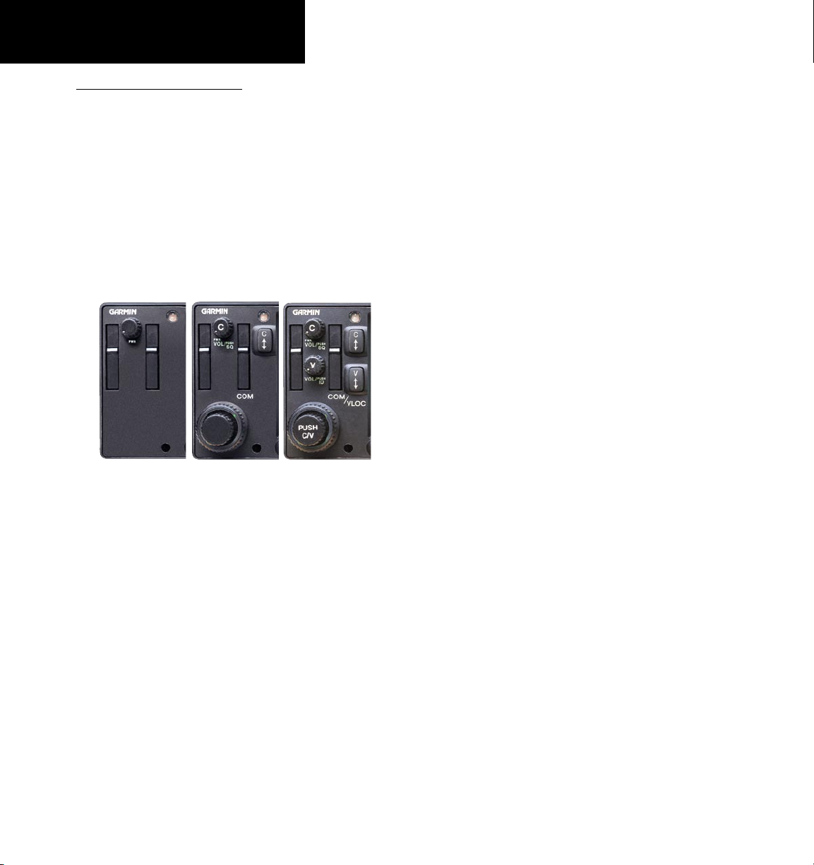
Left-hand Keys and Knobs
GPS 400W
GNC 420W/AW GNS 430W/AW
Left-hand Keys and Knobs
The small left knob (COM/VLOC)
f
W
V
(420W/430W only) is used to tune the kilohertz (kHz) value
point)
of the standby frequency for the communications transceiver (COM) or the VLOC
receiver, whichever is currently selected by the
tuning cursor. Press this knob momentarily
to toggle the tuning cursor between the COM
and VLOC frequency fields.
The COM flip-flop key (420W/430W only)
is used to swap the active and standby COM
frequencies. Press and hold to select emergency channel (121.500 MHz).
The VLOC flip-flop key (430W only) is
used to swap the active and standby VLOC
frequencies (i.e., make the selected standby
frequency active).
(to the right of the decimal
The COM power/volume knob (420W/430W
k
j
h
2
only) controls unit power and communications
radio volume. Press momentarily to disable
automatic squelch control. In the GPS 400W,
this control is used only for power.
The VLOC volume knob (430W only)
controls audio volume for the selected VOR/
Localizer frequency. Press momentarily to
enable/disable the ident tone.
The large left knob (COM/VLOC)
(420W/430W only) is used to tune the megahertz (MHz) value (to the left of the decimal
point) of the standby frequency for the communications transceiver (COM) or the VLOC
receiver, whichever is currently selected by
the tuning cursor.
Page 13

TAKEOFF TOUR
Key and Knob Functions
Right-hand Keys and Knobs
Right-hand Keys and Knobs
R
D
The range key (RNG) allows you to select
the desired map scale. Use the up arrow side
of the key to zoom out to a larger area, or
the down arrow side to zoom in to a smaller
area.
The direct-to key provides access to the
direct-to function, which allows you to enter
a destination waypoint and establishes a
direct course to the selected destination. See
Section 3.
The enter key (ENT) is used to approve an
E
d
a
operation or complete data entry. It is also
used to confirm information, such as during
power on.
The large right knob is used to select
between the various page groups: NAV, WPT,
AUX or NRST. With the on-screen cursor
enabled, the large right knob allows you to
move the cursor about the page.
The small right knob (CRSR) is used to
select between the various pages within one
of the groups listed above. Press this knob
momentarily to display the on-screen cursor.
The cursor allows you to enter data and/or
make a selection from a list of options.
The MENU key displays a context-sensitive
m
c
list of options. This options list allows you
to access additional features or make settings
changes which relate to the currently displayed page.
The clear key (CLR) is used to erase infor-
mation or cancel an entry. Press and hold
this key to immediately display the Default
Navigation Page, regardless of which page is
currently displayed.
3
Page 14
TAKEOFF TOUR
Key and Knob Functions
Bottom Row Keys
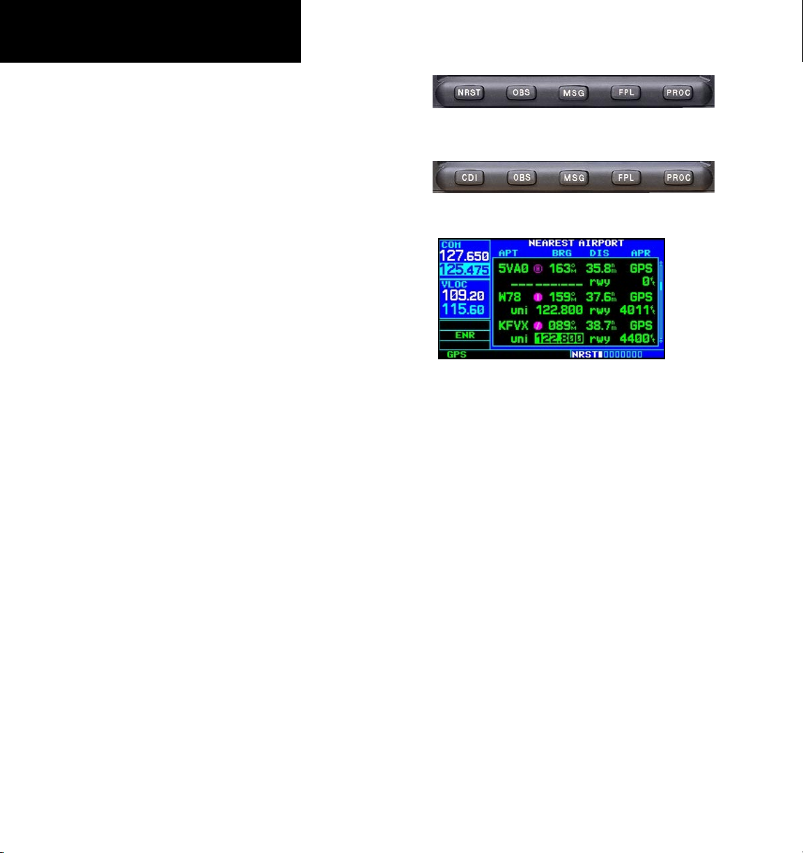
N
The nearest (NRST) key (400W/420W
only) displays the nearest airports page.
Then, turning the small right knob steps
through the NRST pages.
GPS 400W / GNC 420W
C
O
M
F
The CDI key (430W only) is used to toggle
which navigation source (GPS or VLOC) provides output to an external HSI or CDI.
The OBS key is used to select manual or
automatic sequencing of waypoints. Pressing
the OBS key selects OBS mode, which will
retain the current “active to” waypoint as
your navigation reference even after passing the waypoint (i.e., prevents sequencing
to the next waypoint). Pressing the OBS
key again will return to normal operation,
with automatic sequencing of waypoints.
Whenever OBS mode is selected, you may set
the desired course to/from a waypoint using
the OBS Page, or an external OBS selector on
your HSI or CDI.
The message key (MSG) is used to view
system messages and important warnings and
requirements. See Sections 11 and 9 for more
information on messages and unit settings.
The flight plan key (FPL) allows you to
create, edit, activate and invert flight plans,
as well as access approaches, departures and
arrivals. A closest point to flight plan feature
is also available from the flight plan key. See
Section 4 for more information on flight
plans.
GNS 430W
Whenever the 400W-series unit is displaying a list of information that is too
long for the display screen, a scroll bar
will appear along the right-hand side
of the display. The scroll bar graphically
indicates the number of additional items
available within the selected category.
Simply press the small right knob to
activate the cursor and turn the large
right knob to scroll through the list.
The procedures key (PROC) allows you to
P
select and remove approaches, departures
and arrivals from your flight plan. When
using a flight plan, available procedures for
your departure and/or arrival airport are
offered automatically. Otherwise, you may
select the desired airport, then the desired
procedure.
scroll bar
}
4
Page 15
TAKEOFF TOUR
Power On
Power On
The Garmin 400W-series provides you accurate
navigational data and some models also have communication capability, along with non-precision and
precision approach certification in the IFR environment. The Takeoff Tour is designed to familiarize you
with the operation of the 400W-series — including
powering up the unit, changing frequencies, entering
data, performing a simple direct-to, selecting IFR procedures and provides a limited introduction to using
flight plans. In addition, this section briefly covers the
default navigation, map and frequency pages available
as part of the NAV page group. These pages will be
used for most of your in-flight navigation.
The Takeoff Tour assumes that the unit and antennas have been properly installed and you have not
changed any of the 400W-series unit default settings.
If you have changed any of the factory default settings
(position format, units of measure, selectable fields,
etc.), the pictures shown here may not exactly match
what you see on your 400W-series unit. Prior to using
your unit for the first time, we recommend that you
taxi to a location that is well away from buildings
and other aircraft so the unit can collect satellite data
without interruption.
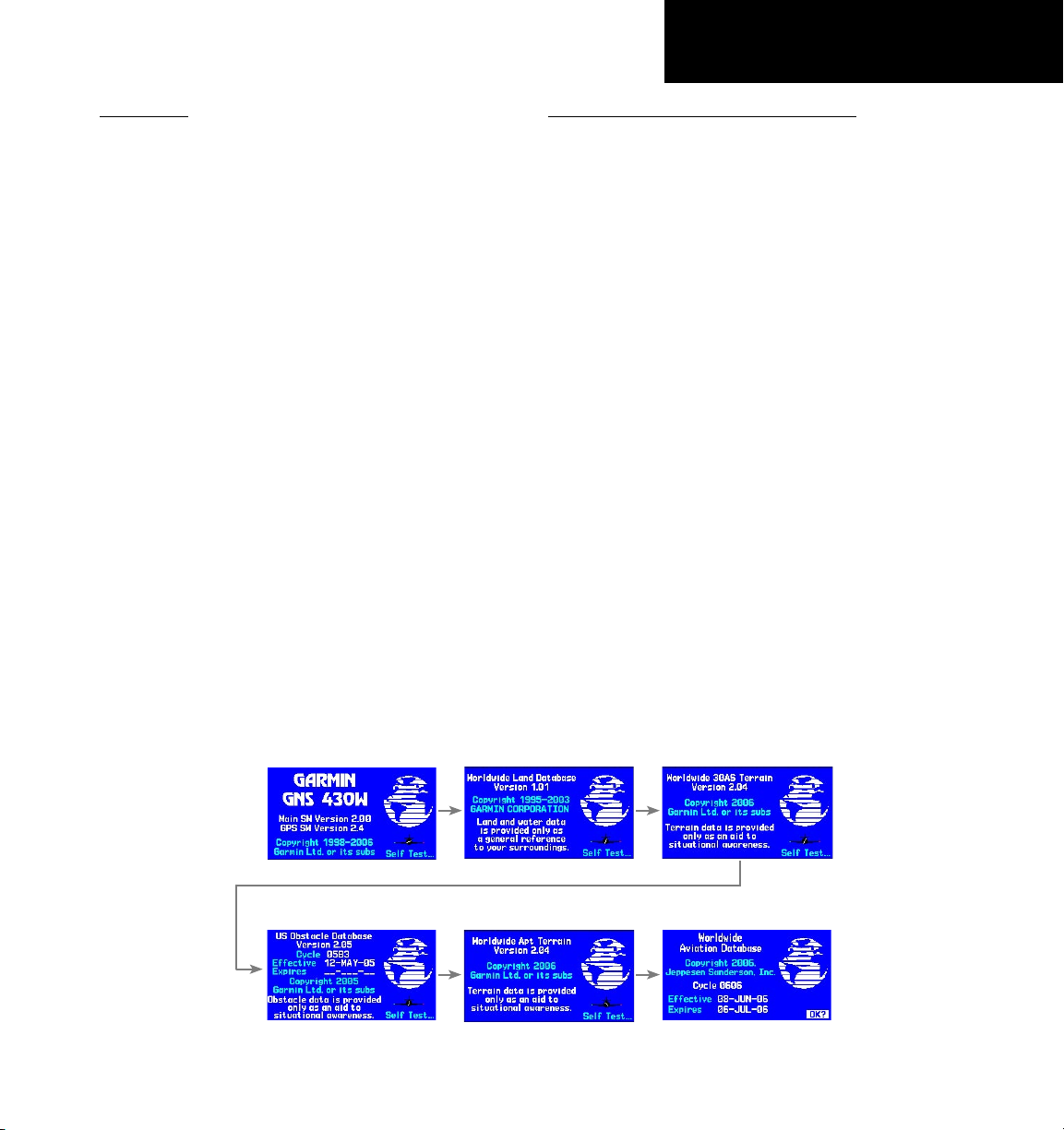
Powering up the 400W-Series Unit
The 420W and
430W
power and COM volume
are controlled using the power/volume knob at the
top left corner of the unit. The 400W power knob
is located at the top left corner of the unit. Turning
it clockwise will turn unit power on and increase
the COM radio volume. After turning the unit on, a
welcome page will be displayed while the unit performs
a self test, followed by the database confirmation pages
which show the current database information on the
NavData card (with the valid operating dates, cycle
number and database type indicated). The database
is updated every 28 days, and must be current for
approved instrument approach operations. Information on database subscriptions is available inside your
400W-series package.
To acknowledge the database information, press
ENT.
Power-up Sequence
5
Page 16
TAKEOFF TOUR
Instrument Panel Self-Test
Check CDI/HSI,
RMI and other
instruments
to verify these
indications
Instrument Panel Self-Test
Once the database has been acknowledged, the
instrument panel self-test page will appear. To ensure
that your 400W-series unit and any connected instruments are working properly, check for the following
indications on your CDI/HSI, RMI, external annunciators and other connected instruments:
• Course deviation
• Glideslope
• TO/FROM flag
• Time to destination
• Bearing to destination
• Desired track
• Distance to dest.
• Ground speed
• All external annunciators (if installed)
{
Should match current
OBS course selection
Fuel Figures: May be
entered manually if no
}
Select to display
Checklists Page
To enter fuel capacity, fuel on board or fuel flow
figures (if not provided by sensors):
1. Turn the large right knob to select the “CAP”,
“FOB” or “FF” field.
2. Turn the small and large right knobs to enter
the desired figure, then press ENT.
sensor present
Select to Set Fuel Level
to Full Capacity
The instrument panel self-test page indicates the currently selected OBS course, fuel capacity (CAP), fuel
on board (FOB) and fuel flow (FF). The fuel capacity,
fuel on board and fuel flow may be manually entered
if your installation does not include connection to sensors which automatically provide these figures.
6
Enter the fuel capacity, fuel on board or fuel
flow figures directly onto the appropriate
field of the instrument panel self-test page.
These figures will automatically be provided
if your installation includes connection to
external sensors.
Page 17
TAKEOFF TOUR
Fuel On Board & Checklists
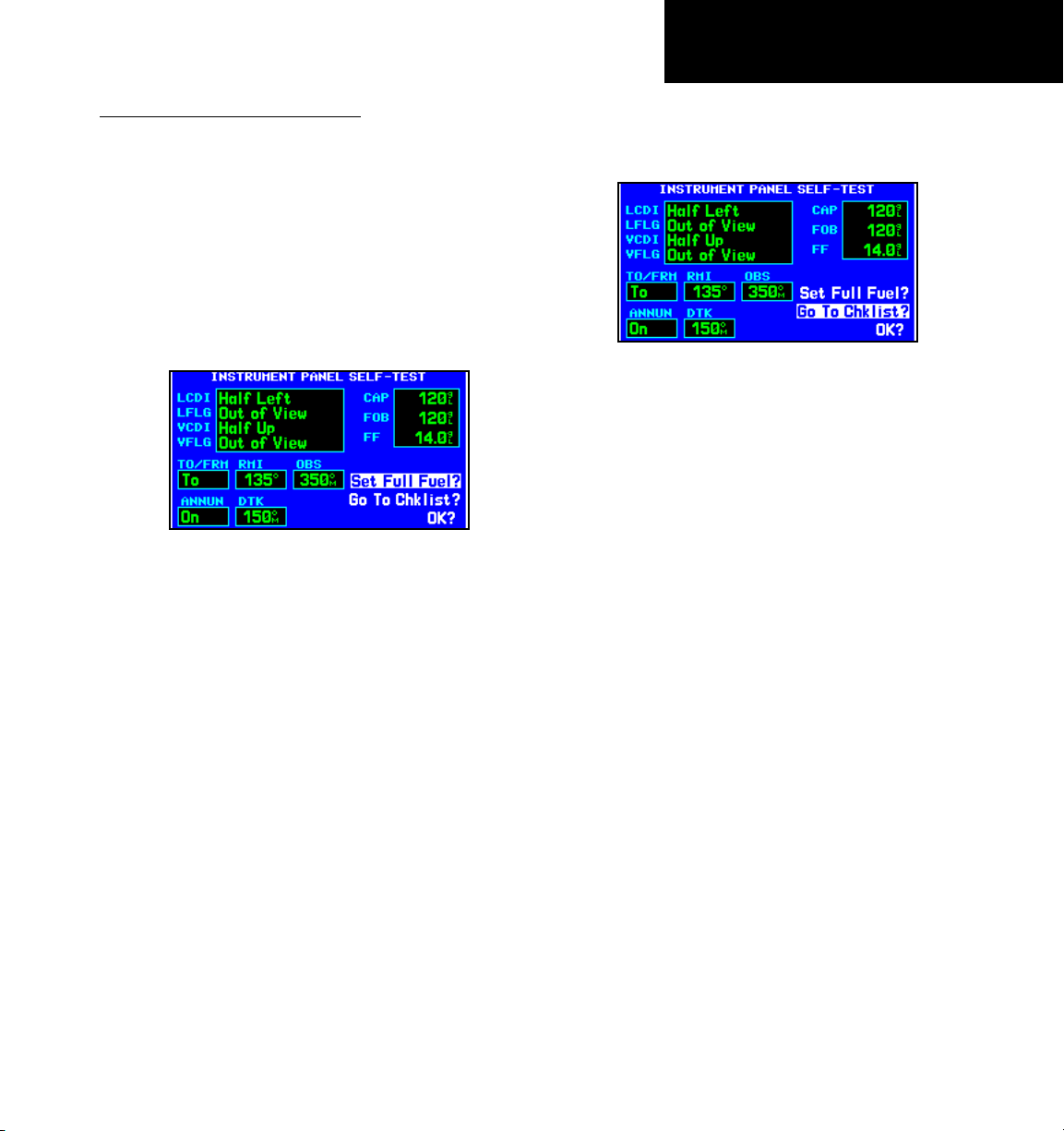
Fuel On Board and Checklists
The instrument panel self-test page includes selections to set fuel on board (FOB) to full capacity and
access the checklists page. This allows you to quickly
set fuel to full limits and display any checklists you’ve
entered, such as start up or takeoff checklists.
To set fuel on board to full (if not provided by
sensor):
1. Turn the large right knob to highlight “Set
Full Fuel?”.
Select “Set Full Fuel?” to set fuel on board
(FOB) to full capacity.
2. Press ENT and verify that fuel on board
(“FOB”) now matches the fuel capacity (CAP)
figure. Fuel on board will now be reduced, over
time, based on the fuel flow (FF) figure.
To view the checklists page:
1. Turn the large right knob to highlight “Go To
Chklist?” and press ENT.
Select “Go To Chklist?” to display the check-
list page and any available checklists. The
400W-series unit can hold up to nine check-
lists with up to 30 entries in each checklist.
2. Turn the large right knob to select the desired
checklist, then follow the steps in Section 9
- Aux Pages - Utility Page to execute each
step in the selected checklist.
3. Once you complete the desired checklist(s),
press the small right knob to return to the
checklists page. Press the small right knob
again to return to normal operation on the
satellite status or map pages.
Once you’ve verified instrument operation with
the instrument panel self-test page displayed,
press the ENT key.
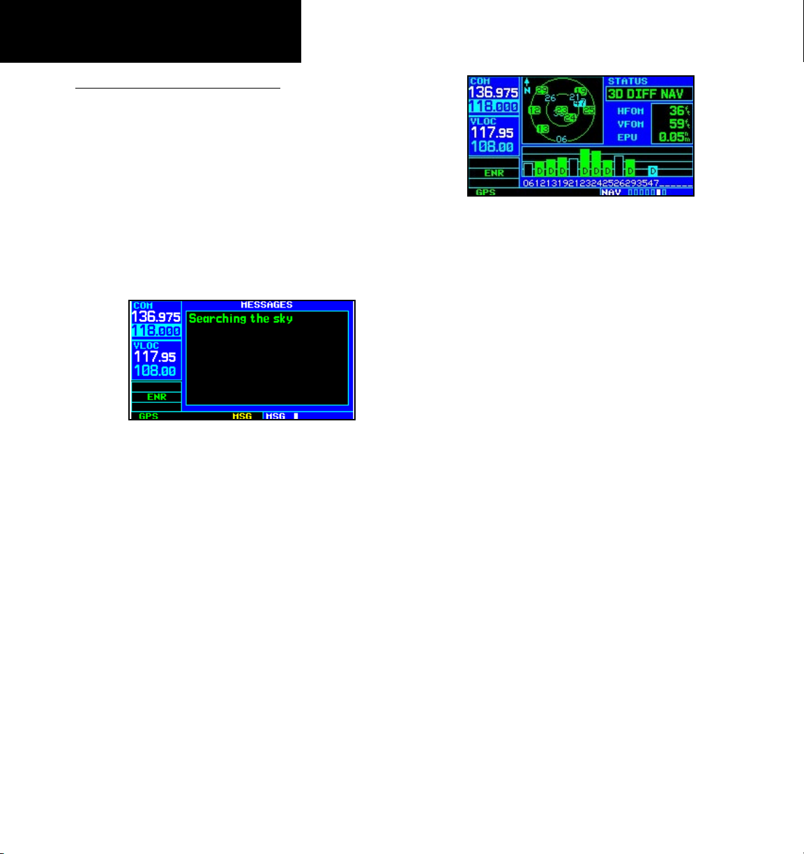
The satellite status page will appear as the 400Wseries unit begins to collect satellite information. An
“Acquiring” status will be displayed on the satellite
status page, and the signal strength of any satellites
received will appear as “bar graph” readings. This is
a good indication that you are receiving signals and a
position fix will be determined. Following the firsttime use of your 400W-series unit, the time required
for a position fix will vary—within two minutes.
7
Page 18
TAKEOFF TOUR
Acquiring Satellites / Messages
Acquiring Satellites/Messages
If the 400W-series unit has not been operated for a
period of six months or more, it may have to “Search
the Sky” to collect new data. This means the unit is
acquiring satellite data to establish almanac and satellite orbit information, which can take 5 to 10 minutes.
The Satellite Status Page displays a “Searching Sky”
status, and the message annunciator (MSG) above the
MSG key also flashes to alert you of a system message,
“Searching the Sky”.
To view a system message, press the MSG key.
Message Page
The message page will appear and display the status
or warning information applicable to the receiver’s current operating condition.
To return to the previous page after viewing a
message, press the MSG key again.
The satellite status page shows the ID numbers for the satellites and the relative signal
strength of each satellite received (as a “bar
graph” reading.
“Searching Sky” indicates that satellite almanac
data is not available. The data is recollected from the
first available satellite.
“Acquiring” indicates that satellites have been
located and information is being acquired, but the
receiver does not have enough satellites for a 3-dimensional position.
“3D NAV” indicates that a 3-dimensional position
is available.
“3D DIFF NAV” indicates when a 3-dimensional
position is available and differential corrections are
being used.
The “INTEG” annunciator (bottom left corner of
the screen) indicates that satellite coverage is insufficient to pass built-in integrity monitoring tests.
8
Page 19
TAKEOFF TOUR
420W / 430W Only
Selecting COM and VLOC Frequencies
While the 400W-series unit is acquiring a position,
let’s take a minute to dial in the active and standby
frequencies you’ll be using for the first phase of your
flight. The
400W-series
display is divided into separate
“windows” (or screen areas), including a COM window,
repeat steps 1 through 3, above, to enter the standby
frequency. After both communication frequencies have
been entered, you may elect to keep the COM window
‘hot’ by leaving the cursor on the standby frequency, or
move the cursor to the VLOC window by pressing the
small left knob.
VLOC window, and the GPS window.
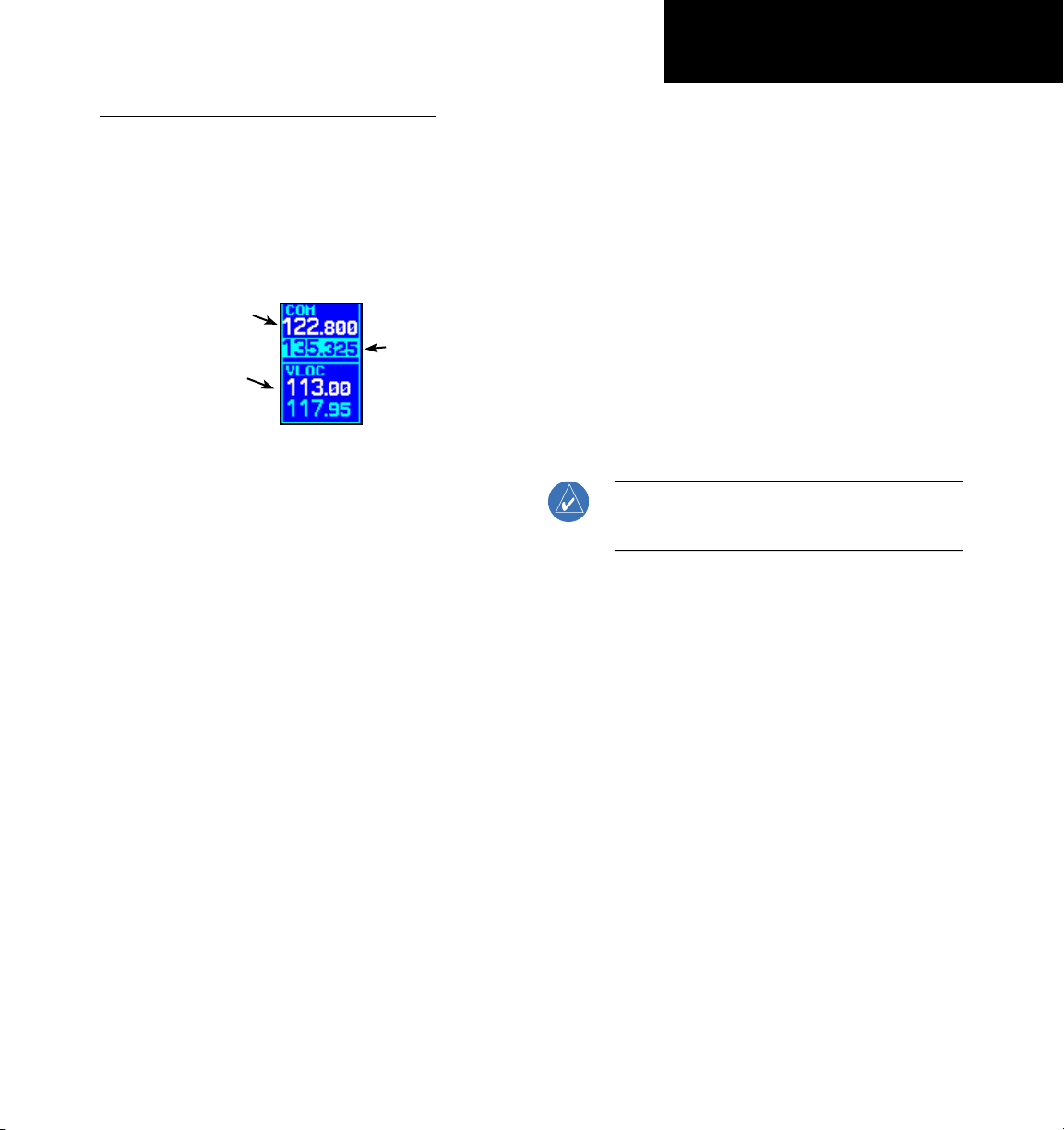
COM Window:
Active Frequency
VLOC Window:
Active Frequency
COM Window:
Standby Frequency
with tuning cursor
repeat steps 1 to 3, above, to enter the standby frequency. After both communication frequencies have
been entered, you may elect to keep the COM window
“hot” by leaving the cursor on the standby frequency,
or move the cursor to the VLOC window by pressing
Pushing the small left knob activates the tuning
the small left knob.
cursor in the desired frequency window. To select the
active frequency, you must first enter the frequency
in the standby field, and use the
COM flip-flop
(or
VLOC flip-flop) key to move it to the active field.
To change the standby
VLOC frequency:
communication (COM) or
units.
1. If the tuning cursor is not currently in the
desired window (COM or VLOC), press the
small left
highlight between the COM and VLOC win
dows. Adjusting the frequencies with the
and small left
knob momentarily to switch the
large
knobs will affect the standby
-
frequency.
2. Turn the
large left
knob to select the desired
megahertz (MHz) value. For example, the
“135” portion of the frequency “135.325”.
3. Turn the
small left
knob to select the desired
kilohertz (kHz) value. For example, the “.325”
portion of the frequency “135.325”.
Selecting COM and VLOC Frequencies
Once you’ve entered the active frequency, simply
Once you’ve entered the active frequency, simply
When selecting VLOC frequencies, the
NOTE:
tuning cursor automatically returns to the COM
window after 30 seconds of inactivity.
These features are only available in the 420W/430W
4. To activate the selected frequency, press the
appropriate
flip-flop key—COM for commu
nication frequencies or VLOC for VOR/Localizer
frequencies.
-
9
Page 20
TAKEOFF TOUR
Page Groups
Page Groups
(Large right knob to change page groups)
d
a
(Small right knob to select pages within the group)
NAV Group
Default NAV
Map
Terrain
NAVCOM
Arpt Location
Arpt Runway
Arpt Frequency
Arpt Approach
WPT Group
Arpt Departure
Intersection
NDB
VOR
Position
Arpt Arrival
Satellite Status
VNAV
Selection of any main page is performed using the large and small right knobs. The large right knob selects the page group: NAV, WPT, AUX or
NRST. The small right knob selects the desired page within a group. To quickly select the default NAV page, press and hold the CLR key.
10
User Waypoint
Page 21
TAKEOFF TOUR
Page Groups
a
(Large right knob to select pages with the group)
AUX Group
Flight Planning
Utility
Setup 1
Setup 2
(Large right knob to change page groups)
d
Nrst Airport
Nrst Intersection
Nrst NDB
Nearest VOR
NRST Group
Nrst User Waypnt
Nrst Center
Nrst Flight Service
Nrst Airspace
FPL Group
Flight plan pages are selected by pressing the
FPL key and using the small right knob to
select the desired page.
Active Flight Plan Flight Plan Catalog
PROC Group
The Procedures pages are selected by pressing the
PROC key and using the small or large right knobs
to select a procedure.
Procedure
11
Page 22
TAKEOFF TOUR
Nav Pages
Nav Pages
The map page is one of seven, or more, pages avail-
able under the NAV group*:
• Default NAV page • Map page
• Terrain page • NAVCOM page
• Position page • Satellite status page
• Vertical navigation page
To select the desired NAV page, turn the small
right knob until the desired page is displayed.
If you are currently viewing a page that is not part
of the NAV group, you can quickly return to the NAV
group using the CLR key.
To select the NAV group and display the default
NAV page, press and hold CLR.
NAV
7+ available pages*
(see list above)
AUX
4 available pages
(see Section 9)
MAIN PAGE GROUPS
WPT
10 available pages
(see Section 6)
NRST
8 available pages
(see Section 7)
In addition to the NAV group of pages, additional
groups of pages are available for waypoint information
(WPT), auxiliary (AUX) functions such as flight planning or unit settings, and listings for nearest (NRST)
airports or other facilities.
The bottom right corner of the screen
indicates the page group currently being
displayed (e.g., NAV or NRST), the number
of screens available within that group
(indicated by square icons) and the place-
ment of the current screen within that group
(indicated by a highlighted square icon). To
select a different page within the group, turn
the small right knob.
* Seven, or more, NAV Pages are avail
able when the 400W-series installation
includes connection to traffic, XM radio,
and/or weather information sources. See the
400W/500W Series Display Interfaces Pilot’s
Guide Addendum, part number
190-00356-31 and the 400W/500W Series
Garmin Optional Displays Pilot’s Guide Ad-
dendum, part number 190-00356-30.
-
To select the desired page group, turn the large
right knob until a page from the desired group is
displayed.
To select the desired page within the group, turn
the small right knob until the desired page is
displayed.
12
Page 23
TAKEOFF TOUR
Default Nav Page
Default Nav Page
During most flights, the default NAV, map and
NAVCOM pages will be the primary pages used for
navigation. The default NAV page displays a graphic
course deviation indicator (CDI), the active leg of
your flight plan (as defined by the current “from” and
“to” waypoints), and six user-selectable data fields.
The default settings for these fields are distance to
waypoint (DIS), desired track (DTK), bearing to
waypoint (BRG), ground speed (GS), ground track
(TRK) and estimated time en route (ETE). See Section 11 for definitions of these navigation terms. The
default NAV page is selected by pressing and holding
the CLR key or turning the small right knob.
Active Leg of
Flight Plan
Course Deviation Indicator (CDI)
User-
selectable
Data Fields
To change the data fields in the corners of the
Default NAV Page:
1. Press MENU (with the Map Page displayed).
2. Turn the large right knob to highlight
“Change Fields?” and press
3. Turn the large right
ENT.
knob to highlight the
data field you wish to change.
4. Turn the small right knob to select the type
of data you want to appear on this field and
press ENT.
Default NAV Page
5. Press the small right knob to remove the
cursor.
13
Page 24
TAKEOFF TOUR
Map Page
Map Page
The map page displays your present position (using
an airplane symbol) relative to nearby airports, VORs,
NDBs, intersections, user waypoints and airspace
boundaries—and your route displayed as a solid line.
Data fields for destination waypoint (WPT), distance
to waypoint (DIS), desired track (DTK) and ground
speed (GS) appear on the right hand side of the
display. These fields are user-selectable to allow you to
configure the unit to your own preferences. Available
settings include: altitude, bearing, en route safe altitude, estimated time of arrival, minimum safe altitude,
and ground track. See Section 11 for definitions of
these navigation terms.
Map Display
Data
Fields
The map page combines a moving map
display and navigation data for complete
situational awareness. Map setup pages
are provided to designate the maximum
scale at which each map feature will ap
pear. These settings provide an automatic
decluttering
preferences) as you adjust the scale.
While viewing the map page, you can
quickly declutter and remove many of
the background map details by pressing
the CLR key (repeatedly) until the desired
of the map (based upon your
detail is depicted.
-
Scale with
14
Map
declutter
value
Present
Position
Map Page
Desired Track
To change the map scale, press the
sides of the RNG key.
or
Page 25
TAKEOFF TOUR
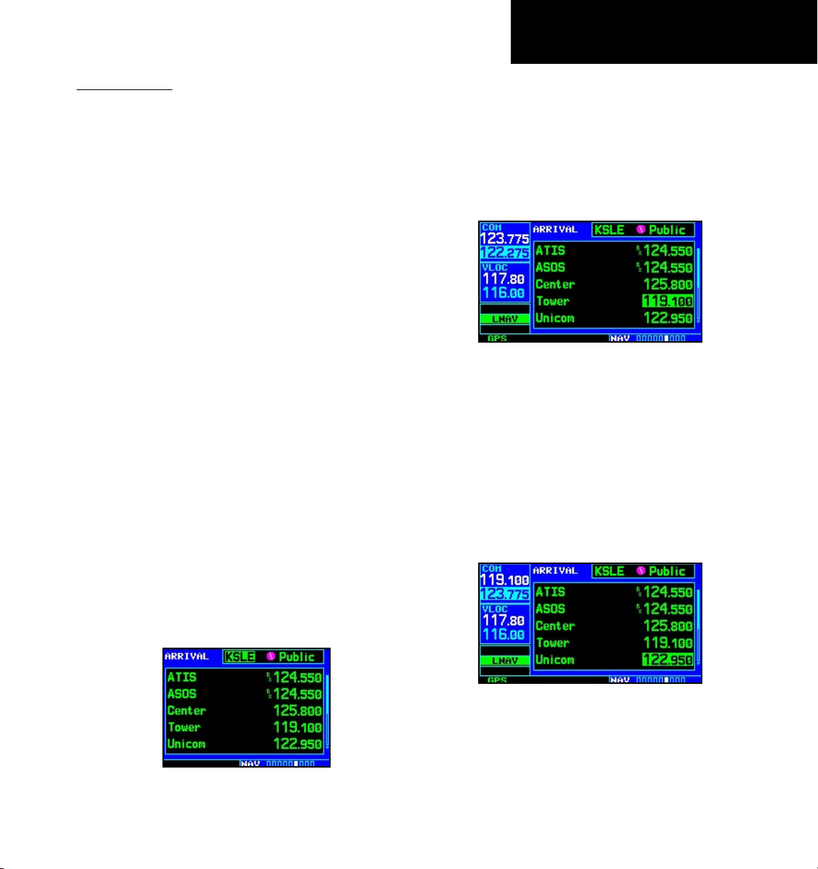
NAVCOM Page
NavCom Page
From the default NAV page, simply turn the small
right knob to display the map page and again to dis-
play the NAVCOM page. The NAVCOM page displays
the available frequencies (communications and navigation) for the departure airport, any en route airports
that are included in your flight plan, and the final
destination airport. When using the direct-to function,
frequencies will be listed for the airport nearest to your
starting position and the destination airport.
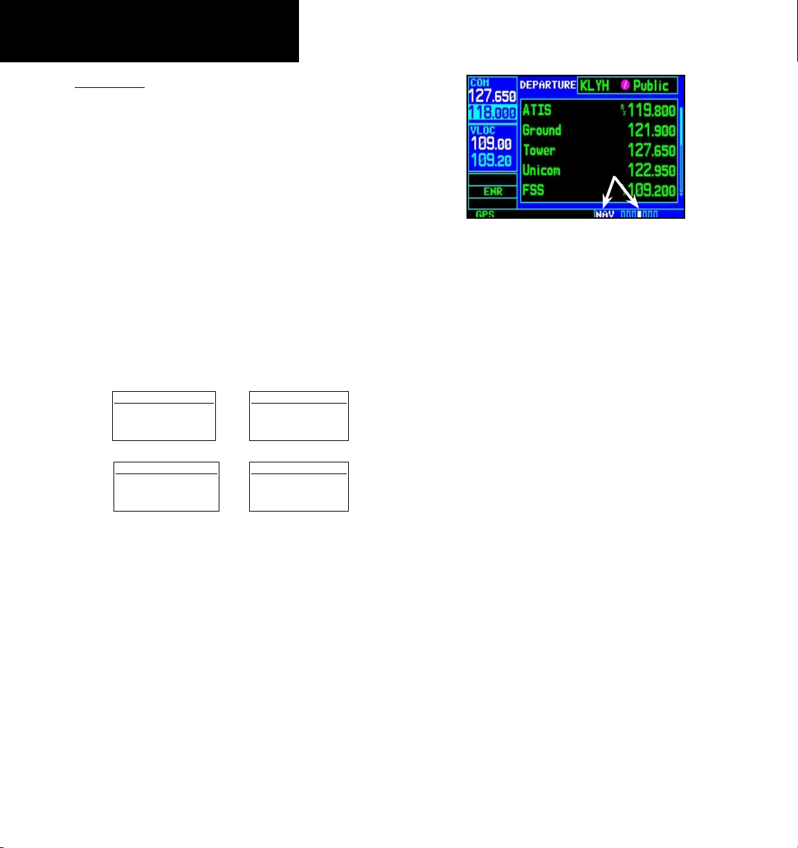
A frequency listed on the NAVCOM page can be
quickly transferred to the standby field of the COM
or VLOC windows. This time-saving process prevents
having to “re-key” a frequency already displayed elsewhere on the screen.
To display the frequency list for the active flight
plan or direct-to airport:
1. In the Nav function, turn the small right knob
to reach the NAVCOM page.
2. Push the small right knob to activate the
cursor on the airport identifier field (in the
GPS window). Turn the small right knob to
display the list of airports (departure, arrival
and en route) for your flight plan or direct-to.
Continue to turn the small right knob until
the desired airport is selected.
To select a communication or navigation frequency:
1. On the NAVCOM page, push the small right
knob to activate the cursor in the GPS window.
2. Turn the large right knob to select the desired
frequency from the list.
Selecting a frequency on the NAVCOM page.
3. Press ENT to transfer the selected frequency to
the standby field in the COM or VLOC window.
COM frequencies will automatically go to the
standby field of the COM window and navigation
frequencies will automatically go to the standby
field of the VLOC window, regardless of which
window is currently highlighted by the cursor.
4. To activate the selected frequency, press the
COM flip-flop (or VLOC flip-flop) key.
3. Press ENT to display the frequency list for the
selected airport.
Press ENT to show the frequencies for the
selected airport.
Swap the standby COM frequency into the
active Com frequency location.
15
Page 26
TAKEOFF TOUR
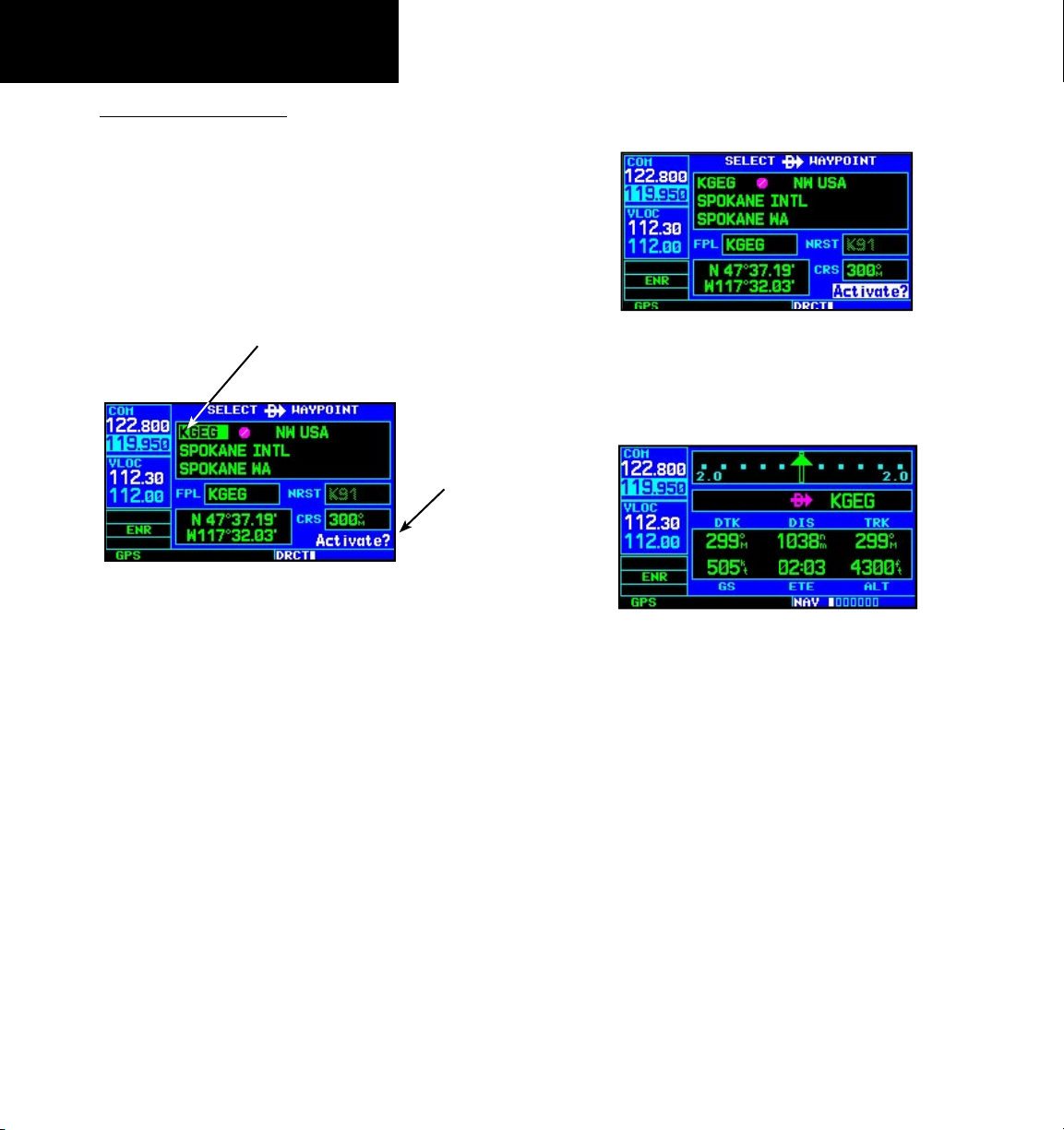
Direct-To Navigation
Direct-To Navigation
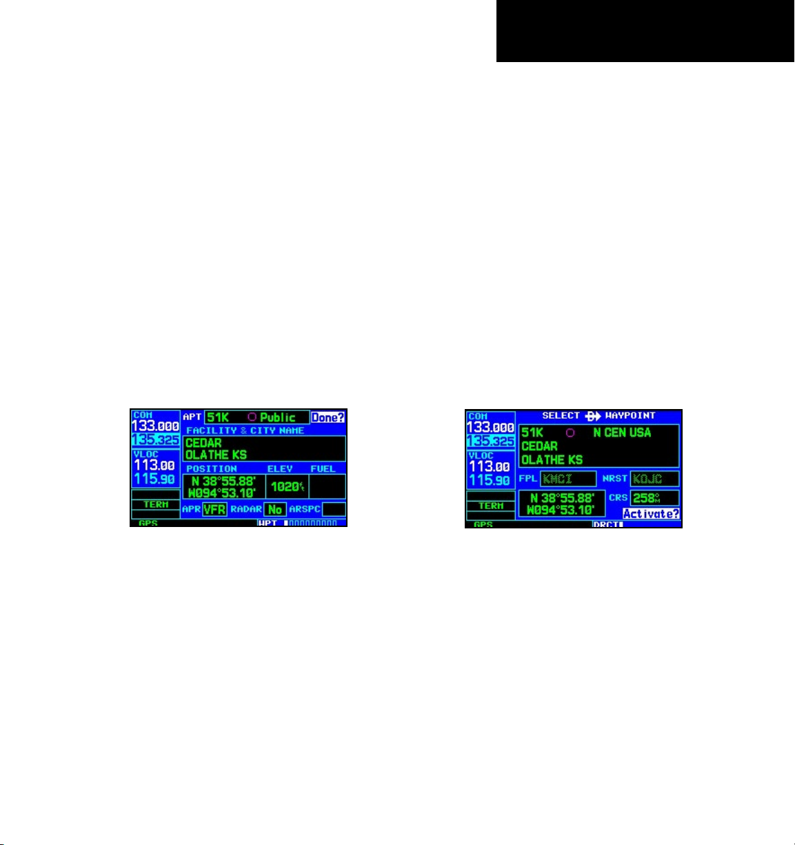
The
400W-series unit
can use direct point-to-point
navigation to guide you from takeoff to touchdown,
even in the IFR environment. Once a destination
is selected, the unit will provide speed, course and
distance data based upon a direct course from your
present position to your destination. A destination can
be selected from any page with the direct-to key.
Destination
Waypoint Identifier
Field
“Activate?”
Function Field
Select Direct-To Waypoint Page
To select a direct-to
1. Press the
destination:
direct-to
key. The Select Direct-To
Waypoint page will appear with the destination
field highlighted. The direct-to waypoint may
also be selected by facility or city name. See
Section 3 for more information.
5. Press
ENT to confirm the identifier. The “Acti
vate?” function field will be highlighted.
Confirm the selected direct-to destination by
highlighting “Activate?” and pressing ENT.
6. Press
ENT to activate a direct-to course to the
selected destination.
Once a direct-to destination is selected,
press and hold CLR to display the default
NAV page.
You can then press and hold the
return to the default NAV page, as desired.
-
CLR key to
2. Turn the
small right
knob to enter the first
letter of the destination waypoint identifier. The
destination waypoint may be an airport, VOR,
NDB, intersection or user waypoint, as long as
it is in the database or stored in memory as a
user waypoint.
3. Turn the
large right knob to the right to move
the cursor to the next character position.
4. Repeat steps 2 and 3 to spell out the rest of
the waypoint identifier.
16
Page 27
TAKEOFF TOUR
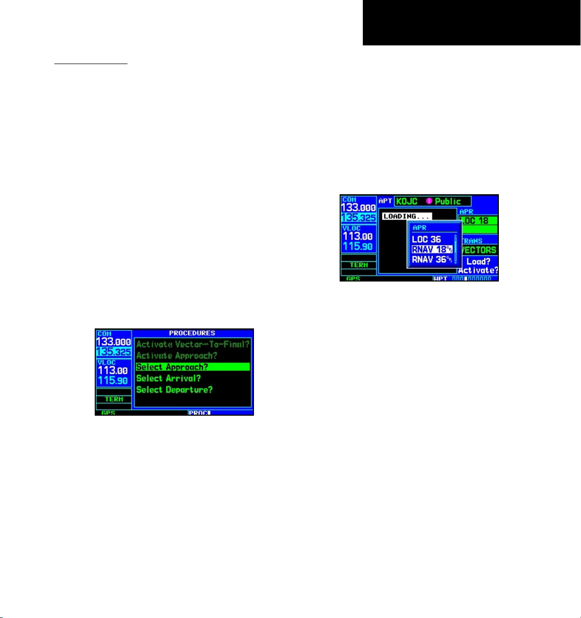
IFR Procedures
IFR Procedures
Once the direct-to or flight plan is confirmed, the
whole range of instrument procedures is available to
you. Departures (SIDs), arrivals (STARs), non-precision and precision approaches are stored within the
NavData card and available using the PROC (procedures) key.
To display the procedures page, press PROC.
The steps required to select and activate an
approach, departure or arrival are identical. In this
introductory section, we’ll show examples of the steps
required to select an approach, but keep in mind the
same process also applies to departures and arrivals.
To select an approach, departure, or arrival:
1. Turn the small right knob to select the desired
option (“Select Approach?”, “Select Arrival?”
or “Select Departure?”) from the procedures
page.
4. For approaches, a window appears to select the
desired initial approach fix (IAF) or provide a
“vectors” option to select just the final course
segment of the approach. Turn the small right
knob to select the desired option and press
ENT. Vectors guidance is relative to the final
inbound course. A line is drawn beyond the
final approach fix, allowing you to intercept
the final course segment beyond its normal
limits.
A window will appear to select the desired
procedure. Use the large right knob to make
your selection.
5. For departures and arrivals, a window appears
to select the desired transition. Turn the small
right knob to select the desired option and
press ENT.
Press the PROC key to display the procedures
page. Turn the large right knob to select the
desired option.
2. Press ENT to display a list of available proce-
dures for the arrival (when using approaches
or STARs) or departure (when using SIDs)
airport.
3. Turn the small right knob to select the desired
procedure and press ENT.
6. With “Load?” highlighted, press ENT to add
the procedure to the flight plan or direct-to.
In your flight plan or direct-to, the departure
or arrival airport is replaced with the sequence of
waypoints contained within the selected procedure.
17
Page 28
TAKEOFF TOUR
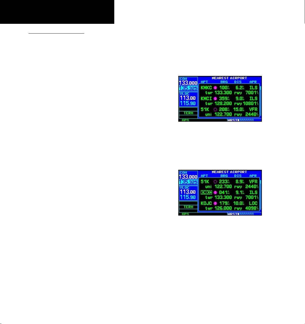
Nearest Pages
Nearest (NRST) Pages
The NRST main page groups provides listings for
nearest airports or other facilities. The NRST group
provides detailed information on the 25 nearest
airports, VORs, NDBs, intersections and user-created
waypoints within 200 NM of your current position.
In addition, pages are also provided to display the five
nearest center (ARTCC/FIR) and Flight Service Station
(FSS) points of communication, plus alert you to any
special-use or controlled airspace you may be in or
near.
The nearest airport page is one of eight pages available under the NRST group:
• Nearest airport page
• Nearest intersection page
• Nearest NDB page
• Nearest VOR page
• Nearest user waypoints page
To display the NRST pages:
1. If necessary, press the small right knob to
remove the cursor from the page.
2. Turn the large right knob to select the NRST
page group, as indicated by “NRST” appearing
in the lower right corner of the screen.
To display a list of nearby airports, turn the
large right knob to select the NRST page
group and (if needed) the small right knob to
select the nearest airport page.
3. Press and then turn the large right knob to
select the desired NRST page.
• Nearest ARTCC page
• Nearest FSS page
• Nearest airspace page
18
To scroll through the list, press the small right
knob, then turn the large right knob.
Page 29
TAKEOFF TOUR
Nearest Airport
Nearest Airport
You may examine both the communication
frequencies and runway information directly from
the nearest airport page. As discussed earlier for the
NAVCOM page, you may also place any displayed
frequency into the standby COM or VLOC field by
highlighting the frequency with the cursor and pressing ENT.
To view additional information for a nearby airport from the Nearest Airport page:
1. Press the small right knob to activate the
cursor.
2. Turn the large right knob to select the desired
airport from the list.
3. Press ENT to display waypoint (WPT) informa-
tion pages for the selected airport.
The nearest airport page may be used in conjunction with the direct-to key to quickly set a course to
a nearby facility in an in-flight emergency. Selecting a
nearby airport as a direct-to destination will override
your flight plan or cancel a previously selected directto destination. You’ll still have the option of returning
to your flight plan by cancelling the direct-to.
To select a nearby airport as a direct-to destina-
tion:
From the nearest airport page...
1. Press the small right knob to activate the
cursor.
2. Turn the large right knob to select the desired
airport from the list.
3. Press direct-to, ENT, and ENT (again) to
navigate to the nearby airport.
Additional information for a nearby airport
is available by highlighting an identifier on
the list and pressing ENT.
4. To display runway and frequency informa-
tion, press the small right knob to remove
the cursor and turn the small right knob to
display the desired information page.
To select a nearby airport as a new destina-
tion, highlight its identifier, press
ENT, and ENT
(again).
direct-to,
From an airport information page...
1. Press direct-to, ENT, and ENT (again) to
navigate to the nearby airport.
19
Page 30
TAKEOFF TOUR
Nearest Airspace
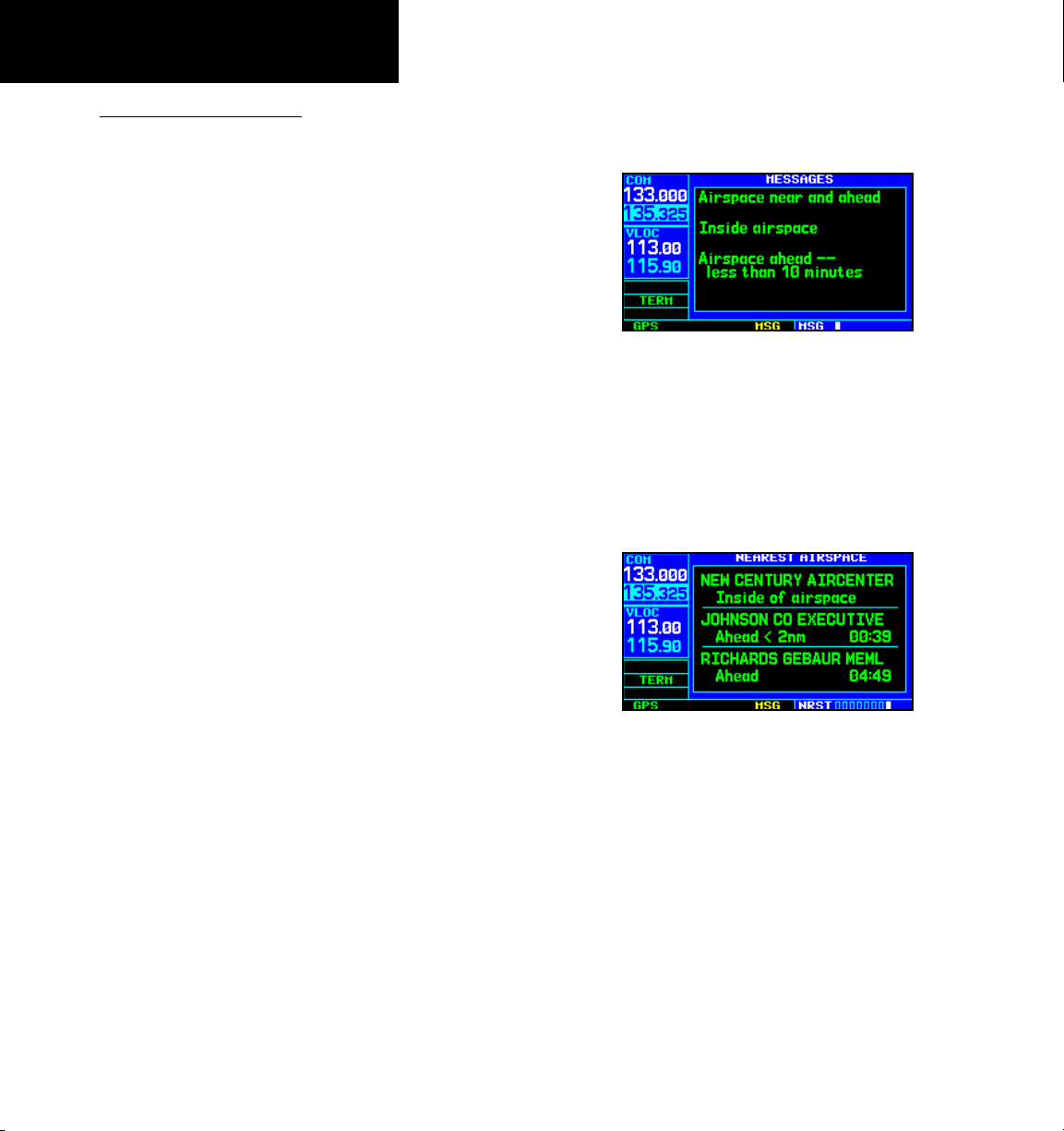
Nearest Airspace Page
The last page in the NRST group, the nearest
airspace page, provides information for up to nine
controlled or special-use airspaces near or in your
flight path. Airspace information appears on this page
based upon the same criteria used for airspace alert
messages. Nearby airspace information and airspace
alert messages are provided according to the following
conditions:
• If your projected course will take you inside an
airspace within the next ten minutes, the message “Airspace ahead -- less than 10 minutes” will
appear.
• If you are within two nautical miles of an airspace
and your current course will take you inside, the
message “Airspace near and ahead” will appear.
• If you are within two nautical miles of an airspace
and your current course will not take you inside,
the message “Near airspace less than 2NM” will
appear.
To view an airspace alert message:
1. Press the MSG key. The message page appears
with the alert message.
When an airspace alert occurs, the message
(MSG) annunciator will flash. Press MSG to
view the alert message.
2. Press MSG again to return to the previous
display.
To view nearest airspace information:
1. Turn the large right knob to reach the NRST
function.
• If you have entered an airspace, the message
“Inside Airspace” will appear.
By default, airspace alert messages are turned off.
When turned on, the message (MSG) annunciator
located directly above the
MSG
key will flash to alert
you to the airspace message. (See Section 9 Aux Pages
- Setup 1 for information on enabling airspace alert
messages.)
20
To view additional information about the
airspace, select the nearest airspace page.
Detailed information is available by high-
lighting the airspace name and pressing ENT.
2. Turn the small right knob to reach the
Nearest Airspace page.
Note that the airspace alerts are based upon threedimensional data (latitude, longitude and altitude) to
avoid nuisance alerts. The alert boundaries for controlled airspace are also sectorized to provide complete
information on any nearby airspace. Additional information about a nearby airspace—such as controlling
agency, frequency and floor/ceiling limits—is available
from the nearest airspace page.
Page 31

TAKEOFF TOUR
Flight Plans
Flight Plans
The
400W-series
lets you create up to 20 flight
plans, with up to 31 waypoints in each flight plan.
Flight plans are created, edited and activated using the
FPL key. The FPL page group includes two pages: the
active flight plan page and the flight plan catalog. The
active flight plan page provides information and editing
features for the flight plan currently in use (referred to
as “flight plan 00”). The flight plan catalog serves as the
main page for creating new flight plans, as well as editing or activating previously created flight plans.
Active flight plan page with flight plan
currently in use.
Since using flight plans is arguably one of the more
complex features of the 400W-series, we’ll only discuss
it briefly here — focusing on creating a new flight
plan and activating it to use for navigation. Additional
information about flight plans can be found in
4 Flight Plans
.
Section
To create a new flight plan:
1. Press the FPL key and turn the small right
knob to select the flight plan catalog.
2. Press the MENU key to display the flight plan
catalog options.
3. Turn the large right knob to select “Create
New Flight Plan?” and press ENT.
To create a new flight plan, select “Create
New Flight Plan?” from the flight plan
catalog options.
4. The cursor will appear on the first waypoint
identifier field (located directly below
“WAYPOINT”). Use the large and small
right knobs to enter the identifier of the first
waypoint in the flight plan. (The small knob
is used to select the desired letter or number
and the large knob is used to move to the
next character space.)
Enter the identifier for each airport and/or
navaid into the flight plan in the same
sequence you wish to fly.
5. Press ENT once the identifier has been selected.
The cursor will move to the next blank waypoint
identifier field.
21
Page 32

TAKEOFF TOUR
Flight Plans
6. Repeat steps 4 and 5, above, until all waypoints
for the flight plan have been entered. Once the
flight plan is created, it may be activated from
an options window. Activating the flight plan
will place a copy into “flight plan 00” (the
original flight plan still resides in the flight
plan catalog). It replaces any flight plan which
currently exists in “flight plan 00.”
To activate the new flight plan:
1. On the Flight Plan Catalog page, press the
small right knob to activate the cursor. Rotate
the large right knob to highlight the desired
flight plan.
2. Press the MENU key to display the flight plan
catalog options.
3. Turn the small right knob to select “Activate
Flight Plan?” and press ENT.
Select “Activate Flight Plan?” from the page
menu to begin using the new flight plan.
22
Page 33

1 - COM
420W / 430W Only
Section 1
Communicating Using the
GNC 420W/AW and GNS 430W/AW
Some models of the 400W-series feature a digitallytuned VHF COM radio that provides a seamless transition from communication to navigation. The GNC
420W and GNS 430W’s COM radio operates in the
aviation voice band, from 118.000 to 136.975 MHz,
in 25 kHz steps (default). For European operations, a
COM radio configuration of 8.33 kHz steps is provided (Section 9 - Aux - Setup 2). The GNC 420AW
and GNS 430AW use a 16-watt transmitter, instead of
the standard 10-watt transmitter.
Radio Volume / Auto Squelch
Squelch
The COM radio features an automatic squelch to
reject many localized noise sources. You may override
the squelch function by pressing the COM power/
volume knob. This facilitates listening to a distant station or setting the desired volume level.
Press the COM power/volume knob momen-
tarily to override the automatic squelch.
Note the “RX” receive indication when
receiving a station.
To override the automatic squelch, press the COM
power/volume knob momentarily. Press the COM
power/volume knob again to return to automatic
squelch operation.
“TX” appears at the upper right corner of
the screen while transmitting.
Volume
COM radio volume is adjusted using the COM
power/volume knob. Turn the COM power/volume
knob clockwise to increase volume, or counterclockwise to decrease volume.
23
Page 34

1 - COM
Com Window and Tuning
COM Window and Tuning
420W / 430W Only
Communication frequencies are selected with the
tuning cursor in the standby COM frequency field,
and using the small and large left knobs to dial in
the desired frequency. The standby frequency always
appears below the active frequency. The active frequency is the frequency currently in use for transmit
and receive operations.
Tuning cursor in the COM window. Use the
small and large left knobs to dial in the
desired standby frequency.
A frequency may also be quickly selected from the
database by simply highlighting the desired frequency
on any of the main pages and pressing the ENT key.
This process is referred to as auto-tuning. Once a
frequency is selected in the standby field, it may be
transferred to the active frequency by pressing the
COM flip-flop key.
While receiving a station, an “RX” indication
appears in the upper right corner of the COM window
— to the immediate right of “COM”. A “TX” indication
appears at this location while you are transmitting.
NOTE: The tuning cursor will normally appear
in the COM window, unless placed in the VLOC
window by pressing the small left knob. When
the tuning cursor is in the VLOC window, it will
automatically return to the COM window after 30
seconds of inactivity. This does not apply to the
GNS 420W.
The active frequency in either window cannot be
accessed directly—only the standby frequency will be
highlighted by the tuning cursor.
To select a COM frequency:
1. If the tuning cursor is not currently in the COM
window, press the small left knob momentarily.
2. Turn the large left knob to select the desired
megahertz (MHz) value. For example, the
“118” portion of the frequency “118.300”.
3. Turn the small left knob to select the desired
kilohertz (kHz) value. For example, the “.300”
portion of the frequency “118.300”.
To make the standby frequency the active fre-
quency, press the COM flip-flop key.
The tuning cursor will remain in the COM window.
The GNS 430W/AW unit has a built-in VOR/Localizer/
Glideslope capability. If you wish to select a VOR/
localizer/ILS frequency, press the small left knob
Once the standby frequency is selected, use
the COM flip-flop key to make the frequency
active for transmit and receive operations.
24
momentarily to place the cursor in the VLOC window.
Additional instructions for VOR/localizer/ILS operations are available in Sections 5 and 8.
Page 35

Cursor in VLOC window allows for VOR and
ILS operations. See Section 8.
Auto-Tuning
The 400W-series auto-tune feature allows you
to quickly select any database frequency in the GPS
window as your standby frequency. Any COM frequency displayed in the GPS window can be transferred to the standby COM frequency field, with a
minimum of keystrokes required. The following are
some examples of selecting COM frequencies from
some of the main GPS pages.
1 - COM
420W / 430W Only
Auto-Tuning from Nearest Airport Page
3. Press ENT to place the frequency in the standby
field of the COM window.
Nearest airport page with the Tower
frequency (TWR) for the closest airport
highlighted.
4. Press the Com flip/flop key to swap the
standby and active frequencies.
To select a COM frequency for a nearby airport:
1. Select the nearest airport page from the NRST
page group. Press and hold the CLR key, then
turn the large right knob until the nearest
pages appears. Finally, if necessary, turn the
small right knob to display the nearest airport
page.
2. Press the small right knob momentarily to
place the cursor on the airport identifier field
of the first airport in the list. Turn the large
right knob to highlight the desired airport
frequency.
From the nearest airport page, select the
desired airport to show a more detailed list-
ing of frequencies for that airport.
5. Before leaving the frequency page, use the
large right knob to highlight “Done?” and
press ENT. “Done?” always needs to be
acknowledged before leaving a page group.
25
Page 36

1 - COM
Auto-Tuning from Flight Plan/Database
420W / 430W Only
To select a COM frequency for a nearby flight service station (FSS) or center (ARTCC):
1. Select the nearest center or flight service page
from the NRST page group. Turn the large
right knob until the NRST pages appear. Then,
if necessary, turn the small right knob to
display the desired NRST page.
Use the nearest ARTCC page to quickly re-
trieve the frequency(s) for the nearest center
(ARTCC) facility.
2. Press the small right knob momentarily to
place the cursor on the page.
3. Turn the large right knob to highlight the
FSS/ARTCC frequency and press ENT to place
the frequency in the standby field of the COM
window.
To select a COM frequency for any airport in your
flight plan:
1. Select the NAVCOM page from the NAV page
group. (Press and hold the CLR key, then turn
the small right knob until the NAVCOM page
appears.)
2. Press the small right knob to place the cursor
on the airport identifier field. To the left of this
field appears Departure, En Route or Arrival
— depending on the placement of the displayed airport within your flight plan.
3. Turn the small right knob to display a
window listing the airports in your flight plan.
Continue turning the small right knob to
select the desired airport.
4. Press ENT to return to the NAVCOM page with
the frequencies for the selected airport.
5. Turn the large right knob to highlight the
desired frequency.
6. Press ENT to place the highlighted frequency
in the standby COM window field.
To select a COM frequency for any airport in the
database:
1. Select the airport frequencies page from the
WPT page group. (Turn the large right knob
to select the WPT page group. Then turn the
small right knob until the airport frequencies
page appears.)
Use the airport frequencies page to retrieve
a frequency list for ANY airport in the
Jeppesen NavData database.
2. Press the small right knob to place the cursor
on the airport identifier field.
The NAVCOM page provides a frequency list
for all the airports (departure, en route and
arrival) along your active flight plan.
26
3. Use the small and large right knobs to enter
the identifier of the desired airport. Press ENT
Page 37

420W / 430W Only
1 - COM
Emergency Channel
when finished.
Stuck Microphone
4. Turn the large right knob to highlight the
desired frequency.
5. Press ENT to place the highlighted frequency
in the standby COM window field.
indication will appear in the COM window. If the
microphone is stuck or accidentally left in the keyed
position, or continues to transmit after the key is
released, the COM transmitter will automatically time
Emergency Channel
The 420W/430W emergency channel select provides a quick method of selecting 121.500 MHz as the
active frequency in the event of an in-flight emergency.
out (or cease transmitting) after 35 seconds of continuous broadcasting. You’ll also receive a “COM push-totalk key stuck” message as long as the stuck condition
exists.
The emergency channel select is available whenever
the unit is on, regardless of GPS or cursor status, or
loss of the display.
To quickly tune and activate 121.500, press and
hold the COM flip-flop key for approximately two
seconds.
Whenever the 420W/430W is transmitting, a ‘TX’
A “COM push-to-talk key stuck” message
appears to warn you of a stuck microphone.
Transmitting is disabled after 35 seconds of
continuous broadcasting.
Press and hold the COM flip-flop key for
two seconds to activate the 121.500 MHz
emergency frequency.
Note: Under some circumstances if the com sys-
tem loses communication with the main system,
the radio will automatically tune to 121.500
MHz for transmit and receive regardless of the
displayed frequency.
27
Page 38

1 - COM
Blank Page
28
Page 39

Section 2
NAV Pages
2 - NAV PAGES
Page Groups / NAV Page Group
Main Page Groups
The
400W-series
main pages are divided into
groups: NAV, WPT, AUX and NRST. While viewing any of these pages, selection of another page is a
simple selection process using the small and large
right knobs.
NAV
7+ available pages
(see list below)
AUX
4 available pages
(see Section 9)
To select the desired page group, turn the large
right knob until a page from the desired group is
displayed.
To select the desired page within the group, turn
the small right knob until the desired page is
displayed.
NAV Page Group
WPT
10 available pages
(see Section 6)
NRST
8 available pages
(see Section 7)
that group (indicated by a highlighted square icon). To select a
The NAV page group includes seven, or more,
pages. While viewing any NAV page, turn the small
right knob to select a different NAV page. You may
find this selection process convenient to cycle between
the default NAV and map pages—two of the most
frequently used pages. Other pages are provided to
list frequencies for your flight plan, show your current
position, display current satellite reception, and make
vertical navigation settings.
Default NAV
NAVCOM
VNAV
The bottom right corner of the screen indicates which page
group is currently being displayed (e.g., NAV or NRST), the
number of screens available within that group (indicated by
square icons) and the placement of the current screen within
different page within the group, turn the small right knob.
This part of the screen is also used to display the 400W-series
turn advisories (e.g., “DTK 313° 9 S”, or LT TO 030° NOW) and
waypoint alerts (e.g., “ARRIVING WPT” or “HOLD TEARDROP”)
during flight plan and approach operations. Seconds will be
abbreviated as “S” and Now may be seen as “N”. See Section
5 for more information.
Map
Position
Terrain
Satellite Status
29
Page 40

2 - NAV PAGES
Default Nav Page
Default NAV Page
The first NAV page is the default NAV page. This
page may be quickly selected from ANY page by using
the CLR key.
To select the NAV group and display the default NAV
page, press and hold the CLR key.
of the indicator, relative to the desired course (the
moving course deviation needle). As with a traditional
mechanical CDI, when you’re off course simply steer
toward the needle. The TO/FROM arrow in the center
of the scale indicates whether you are heading to the
waypoint (an up arrow) or if you have passed the
The default NAV page displays a graphic course
waypoint (a down arrow).
deviation indicator (CDI) across the top of the page.
Unlike the angular limits on a CDI coupled to a VOR
or ILS receiver, full scale limits for this CDI are defined
by a GPS-derived distance (2.0, 1.0 or 0.3 NM). By
default, the CDI scale automatically adjusts to the
desired limits based upon the current phase of flight:
en route, terminal area or approach.
Active Leg of
Flight Plan
Course Deviation Indicator (CDI)
User-
selectable
Data Fields
The graphic CDI shows your position at the center
The following symbols are used—on the default
NAV page directly below the CDI—to depict the
“active leg” of a flight plan or direct-to:
Direct-To a Waypoint
Course to a Waypoint, or Desired
Course between Two Waypoints
Right Procedure Turn
Left Procedure Turn
Vectors-To-Final
DME Arc to the left
DME Arc to the right
Page location in NAV
group or advisory
NOTE:
Approaching the FAF, the GNS 400W-series
unit automatically rescales in an angular fashion.
This allows the LPV approach to be flown identically
to a standard ILS.
ing is tightened from
deflection defined for the approach.
At 2.0 NM from the FAF, CDI scal
1
.0 to the angular
full scale
You may also manually select the desired scale set
ting as outlined in the Aux Setup section.
30
Left-hand Holding Pattern
Right-hand Holding Pattern
Directly below the CDI appears the active leg
your flight plan, or the direct-to destination when
-
using the direct-to
key. This will automatically
of
sequence to the next leg of your flight plan as you
reach each interim waypoint. If no flight plan or
direct-to destination has been selected, the destination
field will remain blank.
Page 41

2 - NAV PAGES
Default Nav Page
Selecting Desired On-Screen Data
At the bottom of the default NAV page you’ll find
six user-definable fields which display the data you’ll
need as your flight progresses. By default these fields
display: distance to destination (DIS), desired track
(DTK), bearing to destination (BRG), ground speed
(GS), ground track (TRK) and estimated time en route
(ETE). However, each of these fields can be customtailored to your preferences by selecting a different
data item. Available data items include:
• Bearing to destination (BRG)
• Distance to destination (DIS)
• Desired track (DTK)
• En route safe altitude (ESA)
• Estimated time of arrival (ETA)
• Estimate time en route (ETE)
• Fuel Flow (FLOW) (When Configured)
• Ground speed (GS)
• Minimum safe altitude (MSA)
• Track angle error (TKE)
• Ground track (TRK)
To select a different data item for any data field:
1. Starting with the default NAV page, press the
MENU key to display an options menu.
2. The “Change Fields?” option is already high-
lighted, so press ENT to select this option.
3. Use the large right knob to highlight the data
field you wish to change.
4. Turn the small right knob to display the list
of available data items. Continue turning the
small right knob to select the desired data
item from the list.
• Vertical speed required (VSR)
• Cross track error (XTK)
If no flight plan or direct-to destination has been
selected only speed, track, altitude and minimum
safe altitude data may be displayed. All other data
types will appear as blank lines—on the default NAV
page—until a destination is selected.
5. Press ENT to select the desired data item and
return to the default NAV page.
6. Press the small right knob momentarily to
remove the cursor from the page.
31
Page 42

2 - NAV PAGES
Map Page
Restoring Factory Settings
You can also quickly return all data field settings to
their original factory settings.
To restore all six data fields to factory default
settings:
1. Starting with the default NAV page, press the
Map Page
The second NAV page is the map page, which displays your present position using an airplane symbol,
along with nearby airports, navaids, user-defined
waypoints, airspace boundaries, lakes, rivers, highways and cities.
MENU key to display an options menu.
2. Turn the large right knob to highlight the
“Restore Defaults?” option and press ENT.
Dual Unit Considerations
A “Crossfill?” option is provided from the Default
NAV Page. This option allows you to transfer a directto destination, the active flight plan, any stored flight
plan or user waypoints to a second 400W or 500Wseries Garmin unit.
Some crossfill operations can be done automatically. If the crossfill method in both 400W (or 500W)series units is set to “auto”, a change in the direct-to
destination or active flight plan on one unit can also be
seen on the other. See Section 4 - Flight Plans - Flight
Plan Catalog Options for additional details on using
the “Crossfill?” option.
NOTE: The databases of the 400/500 series and
the 400W/500W are incompatible so you may not
mix systems.
NOTE: The electronic chart is an aid to navigation
and is designed to facilitate the use of authorized
government charts, not replace them. Land and
water data is provided only as a general reference
to your surroundings. The positional accuracy
of the land and water data is not of a precision
suitable for use in navigation and it should not
be used for navigation. Only official government
charts and notices contain all information needed
for safe navigation – and, as always, the user is
responsible for their prudent use.
Map Range
NOTE: If the 400W-series unit is unable to
determine a GPS position, the present position
(airplane) symbol will appear on the Map Page in
yellow. No symbol will be present when there is
no active flight plan.
Map Display
Data
Fields
Present
Position
Page location
in NAV group
32
Page 43

2 - NAV PAGES
Map Page
Map Symbols
Various
symbols are used to distinguish between
waypoint types. The identifiers for any on-screen
waypoints can also be displayed. (By default the identifiers are enabled). Special-use and controlled airspace
boundaries appear on the map, showing the individual
sectors in the case of Class B or Class C airspace.
The following symbols are used to depict the various
airports and navaids on the map page:
Airport with hard surface runway(s); Primary runway shown
Airport with soft surface runway(s) only
Private Airfield Intersection
VOR VORTAC
VOR/DME TACAN
DME NDB
Localizer Locator Outer Marker
Heliport
Map Range
The map display can be set to 23 different scale
settings from 500 feet to 2000 nautical miles (statute
and metric units are also available). The scale is indicated in the lower left-hand corner of the map display,
and represents the top-to-bottom distance covered by
the map display.
To select a map Range:
1. Press the up arrow side of the RNG key to
2. Press the down arrow side of the RNG key
zoom out to a larger map area.
to zoom in to a smaller map area and more
detail.
33
Page 44

2 - NAV PAGES
Map Page
Map Page Auto Zoom
An autozoom feature is available which will auto-
To quickly declutter the map display, press the CLR key
momentarily (as often as needed) to select the desired
amount of map detail.
matically adjust from an en route range of 200 NM
through each lower range, stopping at a range of
1.0 NM as you approach your destination waypoint.
The autozoom feature is turned on/off from the map
setup page.
The map page also displays a background map
showing lakes, rivers, coastlines, highways, railways
and towns. When a map scale is selected below the
lower limit at which the map detail was originally cre-
The right-hand side of the map page includes four
user-selectable data fields. By default, the displayed
data is: destination waypoint name (WPT), desired
track (DTK), distance to destination waypoint (DIS)
and ground speed (GS). Any of these data fields may
be changed to display a different data type. You may
also remove the four data fields from the map to show
a larger map image.
ated, an “overzoom” indication will appear on the map
display, below the scale reading. “Overzoom” indicates
that the detail at this scale may not accurately represent actual conditions. If you continue to zoom in to
lower scale settings, “overzoom” will be replaced with
“no map” and the geographic detail is removed from
the map display (but, the airport and navaid detail will
remain).
The “Setup Map?” option allows you to define the
maximum scale at which each map feature will appear.
This provides you with complete control to minimize
screen clutter. You can also quickly remove items from
the map using the CLR key.
The CLR key allows you to quickly declutter
the map display, providing four levels of
map detail. Note the “-1” and “-2” (“-3” is
also provided) suffix designations above,
indicating each successive declutter level.
34
Page 45

2 - NAV PAGES
Map Page
Map Panning
Panning allows you to move the map beyond its
current limits without adjusting the map range. When
you select the panning function — by pressing the
small right knob — a target pointer will flash on the
map display. A window will also appear at the top of
the name of that object will be highlighted (even if
the name wasn’t originally displayed on the map).
This feature applies to airports, navaids, user-created
waypoints, roads, lakes, rivers — almost everything
displayed on the map except route lines.
the map display showing the latitude/longitude position of the pointer, plus the bearing and distance to
the pointer from your present position.
To select the panning function and pan the map
display:
1. Press the small right knob to activate the
panning target pointer.
2. Turn the small right knob to move up (turn
clockwise) or down (counterclockwise).
selected on the map display, you can review information about the waypoint or designate the waypoint as
your direct-to destination.
When the target pointer is placed on an object,
When an airport, navaid, or user waypoint is
To review information for an on-screen airport,
navaid or user waypoint:
1. Use the panning function (as described above)
to place the target pointer on a waypoint.
2. Press ENT to display the waypoint information
page(s) for the selected waypoint.
3. Turn the large right knob to move right (turn
clockwise) or left (counterclockwise).
4. To cancel the panning function and return to
your present position, press the small right
knob.
3. Press CLR to exit the information page(s).
35
Page 46

2 - NAV PAGES
Map Page
Map Direct-To
To designate an on-screen airport, navaid or user
waypoint as your direct-to destination:
1. Use the panning function (see previous page)
to place the target pointer on a waypoint.
2. Press direct-to key to display the select direct-
to waypoint page, with the selected waypoint
already listed.
3. Press ENT twice to confirm the selection and
begin navigating to the waypoint.
The direct-to function can be used anywhere on
the map. If nothing currently exists at the crosshair
position, a new waypoint (called “+MAP”) will be created at the target pointer location before the direct-to
is initiated.
2. Press ENT to display an options menu.
3. “Review Airspace?” should already be high-
lighted, if not select it with the small right
knob. Press ENT to display the airspace information page for the selected airspace.
Airspace Information on the Map
When a special-use or controlled airspace boundary appears on the map display, you can quickly
retrieve information — such as floor/ceiling limits and
controlling agency — directly from the map.
To view airspace information for an on-screen
special-use or controlled airspace:
1. Use the panning function (see previous page)
to place the target pointer on an open area
within the boundaries of an airspace. If the
area is congested and it is difficult to select an
open area, you may need to zoom in or press
CLR to make the selection easier.
36
To display airspace frequencies:
1. While viewing the airspace information display
in the above example, turn the large right
knob to highlight “Frequencies?” and press
ENT. Press CLR to return to the airspace
information page.
2. Press CLR to exit the airspace information
page. Press the small right knob (CRSR) to
exit panning.
Page 47

2 - NAV PAGES
Map Page Options
Map Page Options
Many of the 400W-series functions are menu
Feature Description
Airspace Special-Use Airspace: Restricted, MOA,
driven. Each of the main pages has an options menu,
allowing you to custom tailor the corresponding page
to your preferences and/or select special features
which specifically relate to that page. A map page
options menu provides additional settings to customize
the map page and additional features related specifically to the map page.
To display the map page options menu, press
MENU (with the map page displayed).
The following options are available: “Setup Map?”,
“Measure Dist?”, “Data Fields Off?”, “Change Fields?”
and “Restore Defaults?”.
Map Setup
“Setup Map?” allows you to configure the map display
to your preferences, including map orientation, land data
enable/disable, Jeppesen data enable/disable, automatic
zoom, airspace boundaries, and text size. The following
table lists the group names and available settings:
Other
City Large/Medium/Small Cities and Text
Road Freeway, National Highway, Local Hwy,
Local Road
Other States/Prov, Rivers/Lakes, Railroads, Wind
Vector
Feature Description
Map Orientation, AutoZoom, Land Data, Avia-
tion Data
Weather Lightning Mode/Symbol (when applicable)
Traffic Traffic Mode/Symbol/Label (when appli-
cable)
Airport Large/Medium/Small Airports and Text
NAVAID VORs, NDBs, Intersections and Text
Waypoint User Waypoints, Flight Plan Wpts, and Text
Line Active Flight Plan/Direct-To, Lat/Long Grid
Control Controlled Airspace: Class B, C, D (tower
zone)
Large, Medium and Small classifications are
used on the 400W-series for airports and
cities. Large airports are those with a runway
longer than 8100 feet. Medium airports
include those with a runway longer than
5000 feet or with a control tower. Large cities are those with approximate populations
greater than 200,000 and Medium cities are
greater than 50,000.
37
Page 48

2 - NAV PAGES
Map Page Options
To change a map setup feature:
1. On the Map page, press MENU to bring up the
Page Menu. Then, turn the large right knob
to highlight “Setup Map?” and press ENT.
2. To change map orientation, turn the small
right knob to select “Map” and press ENT.
3. Turn the large right knob to highlight the
“Orientation” field and turn the small right
knob to select the desired option. Select “North
up” to fix the top of the map display to a north
heading. Select “Track up” to adjust the top
of the map display to your current track heading.
Select “DTK up” to fix the top of the map display
to your desired course. Press ENT to accept the
selected option.
4. To enable/disable automatic zoom, turn the
small right knob to select “Map” and press
ENT. Turn the large right knob to highlight
the “Auto Zoom” field and turn the small
right knob to select “On” or “Off”. Press ENT
to accept the selected option. The automatic
zoom feature will automatically adjust the
map scale from 2000 NM through each lower
scale, stopping at 1.0 NM as you approach
your destination waypoint.
5. To enable/disable background land data, or all
Jeppesen aviation data, turn the small right
knob to select “Map” and press ENT. Use the
large right knob to highlight the appropriate field and turn the small right knob to
select “On” or “Off”. Press ENT to accept the
selected option.
6. For airports, NAVAIDs, active flight plan
waypoints, user-created waypoints, state/provincial boundaries, rivers/lakes and cities: turn
the small right knob to select the appropriate
“Group” name (per the chart on the previous
page) and press ENT. Use the large right
knob to highlight the zoom field for the desired
feature and turn the small right knob to
select the maximum scale at which the feature
should appear on screen. Or select “Off” to
never display the selected feature. Press ENT
to accept the selected option. Next, turn the
large right knob to highlight the text field for
the desired feature and turn the small right
knob to select the desired text size, or select
“None” to disable text descriptions. Press ENT
to accept the selected option.
38
Page 49

2 - NAV PAGES
Map Page Options
7. For airspace boundaries, highways, roads,
railroad lines, wind vector, track log data,
active flight plan course lines, and lat/long
grid lines: turn the small right knob to select
the appropriate “Group” name (per the chart
on the previous page) and press ENT. Use the
large right knob to highlight the zoom field
for the desired feature and turn the small
right knob to select the maximum scale at
which the feature should appear on screen. Or
select “Off” to never display the selected feature. Press ENT to accept the selected option.
Distance Measurements
The “Measure Dist?” option provides a quick, easy
method for determining the bearing and distance
between any two points on the map display.
To measure bearing and distance between two
points:
1. On the Nav Map page, press MENU. Then,
turn the large right knob to highlight “Mea-
sure Dist?” and press ENT. An on-screen refer-
ence pointer will appear on the map display at
your present position.
the top of the map display.
4. To exit the “Measure Dist?” option, press the
small right knob.
2. Use the small and large right knobs to place
the reference pointer at the location you wish
to measure FROM and press ENT.
3. Again, use the small and large right knobs to
place the reference pointer at the location you
wish to measure TO. The bearing and distance
from the first reference location will appear at
39
Page 50

2 - NAV PAGES
Map Page Options
Data Fields on the Map
The “Data Fields Off?” option provides a full-screen
map display (shown bottom right), without the four
data fields along the right-hand side of the screen.
Select this option when you wish to display a larger
map area. If this option has been selected and the
data fields are off, “Data Fields On?” will appear as an
option instead.
To turn the data fields on or off, press MENU and
turn the large right knob to highlight “Data Fields
Off?” (or “Data Fields On?”), then press ENT.
Selecting Desired On-Screen Data
“Change Fields?” allows you to choose the data
displayed on the four user-selectable data fields along
the right-hand side of the map page. There are twelve
available data types, including bearing to destination, distance to destination, estimated time of arrival,
ground speed, minimum safe altitude and track. See
Section 11 for descriptions of these (and other) navigation terms.
To change a data field:
1. Press MENU on the Map page and then turn
the large right knob to highlight “Change
Fields?”. Then, press ENT.
2. Turn the large right knob to highlight the
data field you wish to change.
3. Turn the small right knob to select the type
of data you want to appear on this field and
press ENT.
4. Press the small right knob to remove the
cursor.
NOTE: The on-screen traffic information will occupy two data fields, leaving room to display only
two additional data types. Traffic information is
only available when the 400W-series installation
includes connection to traffic information sources.
See the 400W Series Pilot’s Guide Addendum,
part number 190-00356-31.
40
Page 51

2 - NAV PAGES
Terrain Operation
Restoring Factory Settings
“Restore Defaults?” resets all four user-selectable
data fields to their original factory default settings.
To restore the factory default settings, press
MENU and turn the large right knob to highlight
“Restore Defaults?”, then press ENT.
Terrain Operation
During power-up of the 400W Series unit, the
terrain/obstacle database versions are displayed along
with a disclaimer. At the same time, the TERRAIN
system self-test begins. A failure message is issued if
the test fails.
Terrain Limitations
Terrain Proximity displays altitudes of terrain
and obstructions relative to the aircraft position and
altitude with reference to a database that may contain
inaccuracies. Terrain and obstructions are shown
only if they are in the database. Terrain and obstacle
information should be used as an aid to situational
awareness. They should never be used to navigate or
maneuver around terrain.
Note that all obstructions may not be available
in the terrain and obstacle database. No terrain and
obstacle information is shown without a valid 3-D GPS
position.
Terrain Page
To display the TERRAIN Page, select the NAV
group and turn the small right knob until the
TERRAIN Page is displayed. The page displays terrain
information, aircraft ground track, and GPS-derived
MSL altitude. Altitude is shown in increments of 20
feet or in increments of 10 meters, depending on unit
configuration. The “G” to the right of the MSL altitude
display reminds the pilot that altitude is GPS-derived.
41
Page 52

2 - NAV PAGES
Terrain Operation
The TERRAIN Page has two selectable view
settings:
• 360˚ View—View from above aircraft depicting
surrounding terrain on all sides
• 120˚ View—View of terrain ahead of and 60˚ to
either side of the aircraft flight path
TERRAIN Page
NOTE: The TERRAIN Page gives a “Track Up” dis-
play orientation, as indicated by the “TRK” label
shown on the display. This is the only orientation
available on this page.
To display a 120˚ view:
1. Select the TERRAIN Page and press MENU.
2. Select “View 120˚?”.
3. Press ENT. To switch back to a 360˚ view,
repeat step 1, select “View 360˚?”, and press
ENT.
To show or hide aviation data:
1. Select the TERRAIN Page and press MENU.
2. Select “Show (or Hide) Aviation Data” and
press ENT. Pressing the CLR key when the
TERRAIN Page is displayed will also toggle
aviation information on or off.
Inhibit Mode
The Garmin TERRAIN system provides an
“inhibit mode”. This mode is designed to deactivate
Premature Descent Alert/Forward Looking Terrain
Avoidance (PDA/FLTA) visual alerts when they are
deemed unnecessary by the pilot. Flying VFR into
an area where unique terrain exists could cause the
system to annunciate a nuisance alert. Pilots should
use discretion when inhibiting the TERRAIN system
and always remember to enable the system when
appropriate. When terrain is inhibited, the Terrain
page will still be active, but alerts and messages will
not be generated. See the Terrain Alerts section for
more information on terrain alerts.
Seven display ranges are available, allowing for a
more complete view of the surrounding area.
To change the display range:
1. Select the TERRAIN Page and press up or down
on the RNG key to select the desired range:
1 NM, 2 NM, 5 NM, 10 NM, 25 NM, 50 NM,
100 NM.
Aviation information such as airports, VORs,
and other navaids can be turned on or off from the
TERRAIN Page.
42
Inhibiting Terrain
Page 53

2 - NAV PAGES
Aircraft Altitude
1000 ft
100 ft Threshold
Terrain Above Aircraft Altitude
Terrain Operation
To inhibit TERRAIN:
1. Select the TERRAIN Page and press MENU.
“Inhibit Terrain?” is selected by default.
2. Press ENT. The TERRAIN system is inhibited.
The annunciation is displayed in
the terrain annunciator field whenever terrain
is inhibited.
Unlighted Obstacle Lighted Obstacle Color TERRAIN/Obstacle
< 1000’ AGL > 1000’ AGL < 1000’ AGL > 1000’ AGL
Obstacle Symbol
Terrain Color Symbology
To enable TERRAIN:
Enabling Terrain
1. Select the TERRAIN Page and press MENU.
“Enable Terrain?” is selected by default.
2. Press ENT. The TERRAIN system is functional
again.
Location
Terrain/Obstacle above or
Red
within 100 ft below current
aircraft altitude
Terrain/Obstacle between
Yellow
100 ft and 1000 ft below the
aircraft altitude
Black TERRAIN/Obstacle is more
than 1000 ft below the aircraft
altitude
TERRAIN Altitude/Color Correlation
43
Page 54

2 - NAV PAGES
Terrain Operation
Terrain Symbols
The symbols on the previous page are used to
represent obstacles and potential impact points on the
Terrain Page. Note that obstacle symbols are shown on
display zoom ranges up to 10 NM:
Color Interpretation
The Garmin TERRAIN system uses black, yellow,
and red to depict terrain information relative to aircraft
altitude.
General Database Information
The Garmin TERRAIN system uses terrain and
obstacle information supplied by government sources.
The data undergoes verification by Garmin to confirm
accuracy of the content, per TSO-C151b. However, the
information displayed should never be understood to
be all-inclusive. Pilots must familiarize themselves
with the appropriate charts for safe flight.
NOTE: The data contained in the terrain and
obstacle databases comes from government
agencies. Garmin accurately processes and crossvalidates the data, but cannot guarantee the
accuracy and completeness of the data.
The terrain/obstacle databases are contained on a
Database Updates
cally with the latest terrain and obstacle data. Visit the
Garmin website to check for newer versions of terrain/
obstacle databases. Compare database cycle numbers
to determine if a newer version is available.
datacard which is inserted in the right-most slot of the
400W Series units.
reprogramming or replacing the database card and
inserting the updated card in the right card slot on the
Database Versions
The version and area of coverage of each terrain/obstacle database is shown on the Terrain Database Versions Page, located in the AUX Page Group.
Databases are checked for integrity at power-up. If a
unit front panel. The terrain/obstacle database may
be downloaded via the intenet and the card reprogrammed using a USB programmer available from
Garmin. Contact Garmin at 800-800-1020 or at www.
garmin.com for more information.
database is found to be missing and/or deficient, the
TERRAIN system fails the self-test and issues a failure
message.
TERRAIN Database Information
Terrain/obstacle databases are updated periodi-
The database update process includes either
44
Page 55

2 - NAV PAGES
Terrain Operation
To update the terrain or obstacle database:
1. Acquire a new terrain data card from
Garmin.
2. Turn off the power to the 400W Series unit.
Navigation Database
As explained in the “Premature Descent Alerting (PDA)” section, the Garmin TERRAIN premature descent alerting (PDA) algorithms utilize data
contained in the Navigation Database. It is therefore
3. Remove the old terrain data card from and
insert the new card into the right-most slot of
the 400W Series unit.
4. Turn on the 400W Series unit and verify that the
TERRAIN system passes the self-test. The “TER
TEST” annunciator will clear after checking and
no failure message appears.
Terrain/Obstacle Database Areas of Coverage
important to also have the latest Navigation Database
installed to ensure correct TERRAIN alerting.
Terrain Phase of Flight
The TERRAIN Phase of Flight definitions are listed
below:
En Route Phase - Defined as when the conditions
for Terminal, Approach, and Departure Phases are not
met.
The following describes the area of coverage available in each database. Regional definitions may change
without notice.
Terminal Phase - Defined as when all three of the
following conditions are met:
• The aircraft is 15 NM or less from the destination
The terrain and airport terrain databases include
worldwide coverage that includes: Latitudes South 60°
• The distance to the destination runway threshold
to North 75°.
The obstacle database provides coverage for the
• The aircraft is at or below (lower than) a straight
USA and Europe that includes:
United States: Limited to the United States, some
areas of Canada, Mexico, the Caribbean, and the
Distance to Runway Height above Runway
Pacific.
Europe: Limited to Austria, Belgium, Czech Republic, Denmark, Estonia, Finland, France, Germany,
Greece, Iceland, Ireland, Italy, Latvia, Lithuania, Netherlands, Norway, Poland, Portugal, Slovakia, Spain,
Approach Phase - Defined as when all three of
the following conditions are met:
• The distance to the destination runway threshold
Sweden, Switzerland, and the United Kingdom.
CAUTION: Obstacles 200 feet and higher are included in the Obstacle Database. It is very important to note that not all obstacles are necessarily
charted and therefore may not be contained in
the Obstacle Database.
• The height above the destination runway thresh-
• The distance to the destination runway threshold
runway.
is decreasing.
line drawn between the two points specified in the
table below (relative to the destination runway).
15 NM 3500 feet
5 NM 1900 feet
is equal to or less than 5 NM.
old elevation is equal to or less than 1000 feet.
is decreasing.
45
Page 56

2 - NAV PAGES
Terrain Operation
Departure Phase - Defined as when all five of the
following conditions are met:
• It has been determined that the aircraft was previously “on-ground.”
• The aircraft has a vertical velocity greater than
zero.
• The aircraft has a ground speed greater than 35
knots.
• The aircraft has an altitude greater than 150 feet
AGL and less than 1500 feet AGL.
• The aircraft is within 15 NM of the departure
airport.
NOTE: There are additional factors beyond what
is outlined above that may alter the determined
TERRAIN flight phase.
As an example, if the pilot configures the unit
to include only airports with runways 5000 feet or
longer, only these are added to the nearest airport list.
The terrain phase of flight is affected in that all airport
runways under 5000 feet are NOT included in terrain
calculations. During a cross-country flight with this
configuration, only airports runways 5000 feet or
Nearest Airport Criteria & Terrain Phase of Flight
Changes to the Nearest Airport Criteria Page affect
how the TERRAIN system performs. The nearest airport list is used to derive the terrain destination airport
when there is no loaded active flight plan or when
deviating from the active flight plan (whenever the
greater cause the unit to go into Terminal or Approach
Mode from En Route mode. If the pilot makes an
emergency landing at an airport that did not show up
in the nearest airport list, FLTA alerts would be issued
throughout the descent.
TERRAIN Destination Airport
terrain algorithms go into estimation mode). In turn,
the nearest airport list is used to determine the terrain
phase of flight. The terrain phase of flight dictates
the Required Terrain Clearance (RTC) levels at which
Forward Looking Terrain Avoidance (FLTA) alerting
occurs, as described later in the Forward Looking
Terrain Avoidance section. Premature Descent Alerting
(PDA) is also affected as described later in the PDA
The TERRAIN destination airport is considered to
be the next airport in the flight plan while adhering
to the flight plan path. If no flight plan is entered, or
if the aircraft is not adhering to the entered flight plan
path, the terrain destination airport is estimated using
the Nearest Airport Criteria as described in the section
above.
section.
Nearest Airport Criteria Page
46
Page 57

2 - NAV PAGES
Terrain Alerts
TERRAIN Alerts
TERRAIN alerts are issued when flight conditions
meet parameters that are set within the TERRAIN
system software algorithms. When an alert is issued,
visual annunciations are displayed. Annunciations
appear in a dedicated field in the lower left corner of
the display.
TERRAIN Annunciation Field TERRAIN Pop-Up Alert
TERRAIN Annunciation and Pop-Up
Alert
Pop-up Alerts
On any page except the TERRAIN Page, when a
terrain or obstacle alert is issued, a pop-up window is
displayed with the appropriate alert.
To acknowledge the pop-up alert and return to
the currently viewed page:
Forward Looking Terrain Avoidance
The Forward Looking Terrain Avoidance alert, or
FLTA, is used by the TERRAIN system and is composed of two elements: Reduced Required Terrain Clear-
ance (RTC) Avoidance and Imminent Terrain Impact
(ITI) Avoidance.
RTC/ITI TERRAIN Severity Levels
“TERRAIN ADVISORY” advisory—Estimated
potential impact in approximately 60 seconds
after pop-up alert and annunciation. Similarly, an
“OBSTACLE ADVISORY” alert is also provided.
Press the CLR key.
To acknowledge the pop-up alert and quickly
display the TERRAIN Page:
Press the ENT key.
“TERRAIN AHEAD” alert (flashing)—Estimated
potential impact in approximately 30 seconds
after pop-up alert and annunciation. Similarly, an
“OBSTACLE AHEAD’’ alert is also provided.
• Reduced Required Terrain Clearance (RTC) Avoidance
— Provides alerts when the aircraft flight path
is above terrain, yet is projected to come within
minimum clearance values outlined in the following Minimum Terrain Clearance Values table.
When an RTC alert is issued, a potential impact
point is displayed on the TERRAIN Page as shown
in the previous Terrain Altitude/Color figure.
47
Page 58

2 - NAV PAGES
Terrain Alerts
• Imminent Terrain Impact (ITI) Avoidance — Provides alerts when the aircraft is below the elevation of a terrain cell in the aircraft’s projected path.
ITI alerts are accompanied by a potential impact
point displayed on the TERRAIN Page. The alert
is given when the projected vertical flight path
is calculated to come within minimum clearance
altitudes in the following table.
Phase of Flight Level Flight Descending
En Route 700 ft. 500 ft.
Terminal 350 ft. 300 ft.
Approach 150 ft. 100 ft.
Departure 100 ft. 100 ft.
Minimum Terrain Clearance Values for RTC/ITI Alerts
During the final approach phase of flight, RTC/ITI
alerts are automatically inhibited when the aircraft
is below 200 feet AGL while within 0.5 NM of the
approach runway or is below 125 feet AGL while
within 1 NM of the runway threshold.
Premature Descent Alerting (PDA)
The TERRAIN system issues a Premature Descent
Alert (PDA) when the system detects that the aircraft
is significantly below the normal approach path to
a runway. PDA begins when the aircraft is within 15
NM of the destination airport. PDA ends when the
aircraft is either 0.5 NM from the runway threshold
or is below an altitude of 125 feet AGL while within
1.0 NM of the threshold.
PDA Severity Levels
CAUTION — The above annunciation and pop-up
terrain alert are displayed during a PDA alert.
48
Premature Descent Alerting (PDA) Threshold
Page 59

2 - NAV PAGES
Terrain Alerts
TERRAIN Failure Alert
The TERRAIN system continually monitors
several system-critical items, such as database validity,
hardware status, and GPS status. Should the system
detect a failure, a message is annunciated “TERRAIN
has failed”.
“TERRAIN has failed” message
“TERRAIN Not Available” Alert
The TERRAIN system requires a 3D GPS
navigation solution along with specific vertical
accuracy minimums. Should the navigation solution
become degraded, if the terrain/obstacle database is
not available, or if the aircraft is out of the database
coverage area, the annunciation “TERRAIN NOT
AVAILABLE” is displayed on the TERRAIN Page.
“TERRAIN NOT AVAILABLE” display
49
Page 60

2 - NAV PAGES
Terrain Alerts
Alert Type Annunciation Pop-Up Alert
TERRAIN Failure None
TERRAIN Inhibited None
TERRAIN Not Available None
Required Terrain Clearance (RTC) Advisory
Required Terrain Clearance (RTC) Alert
(FLASHING)
Imminent Terrain Impact (ITI) Advisory
Imminent Terrain Impact (ITI) Alert
(FLASHING)
Required Obstacle Clearance (RTC) Advisory
Required Obstacle Clearance (RTC) Alert
Imminent Obstacle Impact (IOI) Advisory
Imminent Obstacle Impact (IOI) Alert
Premature Descent Alert (PDA)
(FLASHING)
(FLASHING)
(FLASHING)
TERRAIN Alerts Summary
(FLASHING)
(FLASHING)
(FLASHING)
50
Page 61

NAVCOM Page
The NAVCOM (navigation communications) page
provides a list of the airport communication and
navigation frequencies at your departure, en route and
arrival airports. The NAVCOM page makes selection
of the frequencies you’ll need along your flight plan
quick and convenient. If you do not have an active
flight plan with a departure airport, the NAVCOM page
will display the frequencies for the airport nearest
your departure position. Only the 420AW and 430AW
move frequencies to their Navcom.
Departure, En
Route or Arrival
Airport
Frequency
Type
2 - NAV PAGES
NAVCOM Page
To scroll through the list of frequencies:
1. Activate the cursor, if not already active, by
pressing the
2. Turn the
through the list of frequencies. If there are more
frequencies in the list that can be displayed on
the screen, a scroll bar along the right-hand
side of the screen will indicate which part of
the list is currently being displayed.
small right knob.
large right knob to move the cursor
Third Page
in NAV group
To select a frequency list
, or arrival
route
1. Press the
cursor.
2. Turn the large right
on the airport identifier field (top line on the
NAVCOM page).
3. Turn the
airport and press
airport:
small right
small right knob to select the desired
for a departure
ENT.
Assigned Frequency
and Usage Informa-
tion (when applicable)
knob to activate the
knob to place the cursor
, en
}
scroll bar
3. To place a frequency in the standby field of the
COM or VLOC window, highlight the desired
420AW and 430AW
frequency and press
ENT. (
only)
51
Page 62

2 - NAV PAGES
Position Page
Some listed frequencies may include designations
for limited usage, as follows:
“TX” - transmit only
“RX” - receive only
“PT” - part time frequency
If a listed frequency has sector or altitude restrictions, the frequency will be preceded by an “Info?”
designation.
To view usage restrictions for a frequency:
1. Turn the large right knob to place the cursor
on the “Info?” designation directly in front of
the desired frequency.
2. Press ENT to display the restriction informa-
tion.
3. To return to the NAVCOM page, press ENT.
Position Page
The position page displays your present position (by
default, in latitude and longitude) and altitude. The
position page also displays your current track, ground
speed, time and a reference waypoint field. These
fields are user-selectable to configure the page to your
own preferences and current navigation needs.
Graphic “Track”
Indicator
Present
Position
Reference
Waypoint Fields
User-selectable
Data Fields
Page location in
NAV group
The graphic “track” indicator at the top of the
page indicates the direction you’re heading, or track,
only while you’re moving. Directly below are three
user-selectable fields, which by default, display track,
ground speed and altitude. Minimum safe altitude
(MSA) can also be displayed on these fields. MSA is
the recommended minimum altitude within approxi
mately ten miles of your present position. MSA is cal
-
culated from the information contained in the database
and generally includes mountains, buildings and other
permanent features.
The graphic “track” indicator and the TRK
indication directly below it provide the same
information. Use the graphic “track” indicator
for quick at-a-glance ground track information.
52
Page 63

NOTE: Do not rely solely on MSA as an absolute
measure of safe altitude. Consult current charts
and NOTAMs for your area.
To change the user-selectable data fields:
1. Press MENU to display the Position page
options menu.
2. Turn the large right knob to highlight
“Change Fields?” and press ENT.
3. Turn the large right knob to highlight the
data field you wish to change.
2 - NAV PAGES
Position Page
6. Press the small right knob momentarily to
remove the cursor from the page.
The position page also features a reference
waypoint field, located at the bottom of the page, to
indicate your bearing and distance to/from a selected
waypoint. The reference waypoint field can display
bearing and distance information for a nearby airport
(default), VOR, NDB, intersection or user waypoint.
To change the reference waypoint information:
1. Press MENU to display the position page
options menu.
2. Turn the large right knob to highlight
“Change Fields?” and press ENT.
3. Turn the large right knob to highlight the
waypoint type field (bottom left corner of the
page; default setting will show “APT”).
4. Turn the small right knob to display the list of
available waypoint types. Continue turning the
small right knob to select the desired data
item from the list.
4. Turn the small right knob to display the list
of available data items. Continue turning the
small right knob to select the desired data
item from the list.
5. Press ENT to select the desired data item and
return to the position page.
5. Press ENT to select the desired type and return
to the position page.
6. To select between “bearing FROM” or “bearing
TO” to the reference waypoint, turn the small
right knob to select the desired bearing reference and press ENT.
53
Page 64

2 - NAV PAGES
Restoring Factory Settings
Restoring Factory Settings
A “Restore Defaults?” option allows you to reset
all data fields to their original factory default settings.
This will return the three user-selectable fields at the
top of the page AND the reference waypoint fields to
default settings.
7. Press the small right knob momentarily to
remove the cursor from the page.
8. If “WPT” is selected as the waypoint type, you
can designate any airport, NAVAID or user
waypoint as a reference waypoint. Press the
small right knob, turn the large right knob
to highlight the waypoint identifier field, then
use the small and large right knobs to enter
the identifier of the desired waypoint. Press
ENT to confirm the selected waypoint. Press
the small right knob to remove the cursor.
To restore the factory default settings:
1. Press MENU to display the position page
options menu.
2. Turn the large right knob to highlight
“Restore Defaults?” and press ENT.
54
Page 65

2 - NAV PAGES
Satellite Status Page
Satellite Status Page
The Satellite Status Page is helpful in troubleshooting weak (or missing) signal levels due to poor satellite
coverage or installation problems. You may wish to
refer to this page occasionally to monitor GPS receiver
performance and establish a normal pattern for system
operation. Should problems occur at a later date, you
may find it helpful to have an established baseline
from which to compare.
Sky View
of satellite
positions
Signal
Strength Bars
Satellite
Numbers
Excluded
Satellite
(cyan)
Acquiring
Satellite,
not ready
for use
Satellite
acquired
and used for
position fix
(green)
Page location
in NAV group
As the GPS receiver locks onto satellites, a signal
strength bar appears for each satellite in view, with the
appropriate satellite number (01-32, WAAS satellites
will have higher numbers) underneath each bar. The
progress of satellite acquisition is shown in the follow
-
ing conditions:
• Hollow signal strength bars — the receiver has found
the satellite(s) and is collecting data.
• Cross-hatch cyan signal strength bars — the receiver
has found the satellite(s) but it has been excluded
by the FDE program as a faulty satellite.
• Solid cyan signal strength bars — the receiver has
collected the necessary data, but is not using the
satellite in the position solution.
The “D” character inside the bars indicates differ
ential corrections (e.g. WAAS) are being used for that
satellite.
Each satellite has a 30-second data transmission
that must be collected (hollow signal strength bar)
before the satellite may be used for navigation (solid
signal strength bar). Once the GPS receiver has deter
mined your position, the 400W-series unit indicates
your position, altitude
GPS receiver status field also displays the following
messages under the appropriate conditions:
• Searching Sky
The GPS receiver is searching the sky for ANY vis
ible satellites. You are also informed of this status
with a “Searching the Sky” message.
• Acquiring Sat
The GPS receiver is acquiring satellites for naviga
tion. In this mode, the receiver uses satellite orbital
data (collected continuously from the satellites) and
• Solid green signal strength bars — the receiver has
collected the necessary data and the satellite is being
used in the position solution. The sky view display
last known position to determine the satellites that
should be in view.
(at top left corner of the page) shows which satel
lites are currently in view, and where they are. The
outer circle of the sky view represents the horizon
(with north at top of the page); the inner circle 45°
above the horizon; and the center point directly
overhead.
-
GPS Receiver
Status
Horizontal Figure of Merit
and Vertical Figure of Merit
Estimated Posi-
tion Uncertainty
Satellite acquired, used for
position fix, and has differential
corrections
-
, track and ground speed. The
—
-
—
-
55
-
Page 66

2 - NAV PAGES
VERTICAL NAVIGATION PROFILE
VERTICAL SPEED REQUIRED
DISTANCE TO TARGET
TIME AND DISTANCE
TO PROFILE
TARGET ALTITUDE
AND POSITION
AIRPORT
CURRENT ALTITUDE
AND POSITION
Satellite Status Page
Vertical Navigation Page
The 400W-series vertical navigation page (the last
NAV page) allows you to create a three-dimensional
profile which guides you from your present position
and altitude to a final (target) altitude at a specified
location. This is helpful when you’d like to descend
to a certain altitude near an airport. Once the profile
is defined, message alerts and additional data on the
default NAV and map pages will keep you informed of
your progress.
Altitude Reference
(AGL or MSL)
• 3D Navigation —
The GPS receiver is in 3D navigation mode and
computes altitude using satellite data.
• 3D Differential Navigation— The GPS receiver is
in 3D navigation mode and differential corrections
are being used.
The Satellite Status Page also indicates the accuracy of the position fix, using Horizontal Figure of
Merit (HFOM), Vertical Figure of Merit (VFOM), and
Estimated Position Uncertainty (EPU). HFOM and
VFOM represent the 95% confidence levels in horizontal and vertical accuracy. The lowest numbers are
the best accuracy and the highest numbers are worse.
EPU is the horizontal position error estimated by the
Fault Detection and Exclusion (FDE) algorithm, in feet
or meters.
Target
Altitude
Target Reference
Vertical Speed
Required
Target
Distance
NOTE:
Vertical Speed
Desired
To use the vertical navigation features, your
Page location in
NAV group
ground speed must be greater than 35 knots and
you must be navigating to a direct-to destination
or using a flight plan.
To create a vertical naviga
-
tion profile:
56
Page 67

2 - NAV PAGES
Vertical Navigation - VNAV
1. Press the small right knob to activate the
cursor.
2. Turn the large right knob to highlight the
target altitude field.
3. Turn the small and large right knobs to select
the target altitude and press ENT.
4. Turn the small right knob to select “Above
Wpt” (AGL) or “MSL”, and press ENT. “Above
Wpt” will use the altitude of a destination airport as stored in the Jeppesen NavData card.
“MSL” lets you set a specific target altitude
for any waypoint category: airport, VOR, NDB,
intersection or user waypoint.
6. Turn the small right knob to select “Before”
or “After”, and press ENT. This setting designates whether the offset distance defines a
point before you reach the target reference
waypoint or after you reach the waypoint.
“After” is not available for the last waypoint.
7. When using a flight plan, the target reference waypoint itself can be specified from
the waypoints contained in the flight plan. By
default, the last waypoint in the flight plan will
be selected. To select a different waypoint, turn
the small right knob to select the desired
waypoint and press ENT.
8. The default profile utilizes a 400 foot-perminute descent rate. To change the rate,
turn the large right knob to highlight the
“VS Profile” field and use the small and large
right knobs to enter a new rate. Press ENT
when finished.
5. Turn the small and large right knobs to select
a distance from the target reference waypoint
and press ENT. If the target altitude should
occur at the target reference waypoint, enter
a distance of zero.
57
Page 68

2 - NAV PAGES
Vertical Navigation - VNAV
With the profile set, the vertical speed required
(VSR) is displayed on the vertical navigation page.
Expect the following to occur when using the vertical
navigation feature:
• At one minute prior to reaching the initial descent
point, a message “Approaching VNAV Profile”
occurs. The descent angle will also lock to prevent changes in speed from altering the profile.
• If selected, the vertical speed required (VSR) readout on the default NAV and map pages will show
the desired vertical speed to maintain the proper
descent angle.
• At 500 feet above the target altitude, an
“Approaching Target Altitude” message is provided. The VSR readout on the default NAV and
map pages is blanked out, at this point.
Vertical navigation messages can be turned on or
off. (By default the messages are off.) Turning the messages off allows you to keep the profile settings you’ve
entered previously, without having them generate messages when the feature isn’t needed.
To disable/enable the vertical navigation (VNAV)
messages:
1. Press MENU to display the vertical navigation
page options menu.
2. With “VNAV Messages On?” highlighted,
press ENT. Or, if the messages are already
on and you wish to turn them off, make sure
“VNAV Messages Off?” is highlighted and
press ENT.
To restore the factory default VNAV settings:
1. On the Nav VNAV page, press the MENU
key.
2. Turn the large right knob to highlight
“Restore Defaults” and then press ENT.
58
Page 69

2 - NAV PAGES
Dead Reckoning
Dead Reckoning
Dead reckoning is the process of continuing navi-
compute navigation related information for the current
flight phase.
gation using your last known position and speed after
a loss of GPS navigation while on an active flight plan.
CAUTION: Navigation using dead reckoning is
therefore only an estimate and should not be
used as the sole means of navigation. Use other
means of navigation, if possible.
Oceanic flight modes. If the unit is in a Terminal or
Approach flight mode when Dead Reckoning takes
place, “No GPS Position” will be displayed on the map
pages and all navigation data will be dashed. If you are
operating in Dead Reckoning mode and a transition to
Terminal or Approach flight modes would occur from
Dead reckoning becomes active after a loss of GPS
position while you are navigating using an active flight
plan. A pop-up message will appear and you must
clear the message before continuing operation.
the projected Dead Reckoning position, Dead Reckoning mode will be discontinued. “No GPS Position” will
be displayed on the map pages and all navigation data
will be dashed.
The ownship icon color is changed to yellow. The To/
From flag is removed from the CDI. The Dead Reckoning annunciator (DR) appears on the left side of the
map display when GPS position is unavailable and the
unit is in Dead Reckoning mode. All external outputs
dependent on GPS position are flagged.
Dead Reckoning is only allowed in En Route and
Terrain will be noted as not available and new terrain
advisory pop-ops will not occur. Traffic and Stormscope information will not be shown on the Map page,
but will continue to be available on their own dedicated pages. XM weather will still be available on the
Map page.
Dead Reckoning mode will continue until GPS position is restored, when GPS navigation is restored Dead
Reckoning mode is exited. The DR annunciations
will be removed and GPS information will be used to
59
Page 70

2 - NAV PAGES
Blank Page
60
Page 71

3 - DIRECT-TO
Selecting a Destination
Section 3
Direct-To Navigation
The 400W-series direct-to function provides a
quick method of setting a course to a destination
waypoint. Once a direct-to is activated, the 400Wseries will establish a point-to-point course line (geodesic path) from your present position to the selected
direct-to destination. Navigation data on the various
NAV pages will provide steering guidance until the
direct-to is cancelled or replaced by a new destination.
To select a direct-to destination:
1. Press the direct-to key. The select direct-to
waypoint page will appear, with the waypoint
identifier field highlighted.
course, the direct-to function may also be used to recenter the CDI (HSI) needle and proceed to the same
waypoint.
3. Press ENT to confirm the selected waypoint,
and ENT again to activate the direct-to function.
If you’re navigating to a waypoint and get off
To re-center the CDI (HSI) needle to the same
destination waypoint:
1. Press the direct-to key, followed by pressing
ENT twice.
NOTE: If you’re navigating an approach with the
missed approach point (MAP) as the current destination, re-centering the CDI (HSI) needle with
the
direct-to
key will cancel the approach.
2. Use the small and large right knobs to
enter the identifier of the desired destination
waypoint.
61
Page 72

3 - DIRECT-TO
Selecting a Destination
Selecting a Destination by Facility Name or City
In addition to selecting a destination by identifier, the select direct-to waypoint page also allows you
to select airports, VORs and NDBs by facility name or
city location. If duplicate entries exist for the entered
facility name or city, additional entries may be viewed
by continuing to turn the small right knob during the
selection process.
Identifier, Symbol
and Region
To select a direct-to destination by facility name
or city:
Flight Plan
Field
Facility
Name
City
Nearest
Airport
Field
4. Continue turning the
small right knob
scroll through any additional database listings
for the selected facility name or city. You can
also scroll backwards with the
small right
knob if you scroll past the desired waypoint.
5. Press
ENT to confirm the selected waypoint,
to activate the direct-to function.
ENT
and
To select the direct-to destination by facility
(shown above) or city location (shown
name
below), highlight the second or third line on
the direct-to waypoint page. Use the small and
large right knobs to enter the facility name or
city. The identifier(s) for any matching entries
will appear on the top line of the page.
to
1. Press the
waypoint page will appear, with the waypoint
identifier field highlighted.
2. Turn the
facility name (second line; see above) or the
city (third line; see above) field.
3. Use the
the facility name or city location of the desired
destination waypoint. As you spell the facility
name or city, the 400W-series Spell’N’Find
feature will select the first entry in the database
based upon the characters you have entered
up to that point.
62
direct-to
key. The select direct-to
large right knob to highlight the
and large right knobs to enter
small
Page 73

3 - DIRECT-TO
Selecting a Destination
Selecting a Destination from the Active Flight Plan
Selecting the Nearest Airport as a Direct-To Destination
If you’re navigating an active flight plan, any
waypoint contained in the flight plan may be selected
as a direct-to destination from the select direct-to
waypoint page. (see Section 4 - Flight Plans, for more
information on flight plans.)
To select a direct-to destination from the active
flight plan:
the nearest airports (from your present position) on
the NRST field. Navigating directly to a nearby airport
is always just a few simple steps away. (Nearby airports
may also be selected as direct-to destinations using the
steps described Section 7 - NRST Pages - Navigating to
a Nearby Waypoint.)
1. Press the direct-to key. The select direct-to
waypoint page will appear, with the waypoint
identifier field highlighted.
2. Turn the large right knob to highlight the
flight plan (FPL) field.
The select direct-to waypoint page always displays
To select a nearby airport as a direct-to destination:
1. Press the direct-to key. The select direct-to
waypoint page will appear, with the waypoint
identifier field highlighted.
2. Turn the large right knob to highlight the
nearest airport (NRST) field.
3. Turn the small right knob to display a window
showing up to nine nearby airports.
3. Turn the small right knob to display a window
showing all waypoints in the active flight
plan.
4. Continue turning the small right knob to
scroll through the list and highlight the desired
waypoint.
5. Press ENT to confirm the selected waypoint,
and ENT to activate the direct-to function.
4. Continue turning the small right knob to
scroll through the list and highlight the desired
airport.
5. Press ENT to confirm the selected airport, and
ENT to activate the direct-to function.
NOTE: Performing a direct-to for the MAP of an
active approach will cancel approach mode.
63
Page 74

3 - DIRECT-TO
Direct-to Shortcuts
Shortcuts
Shortcuts are available when using the direct-to
key, allowing you to bypass the use of the small and
large right knobs to enter the destination waypoint’s
identifier. A direct-to can be performed from any page
displaying a single waypoint identifier (such as the
WPT pages for airports and navaids) by simply pressing direct-to and ENT. For pages that display a list
of waypoints (e.g., the nearest airport page), you must
highlight the desired waypoint with the cursor before
pressing the direct-to key.
To select an on-screen waypoint (other than the
map page) as a direct-to destination:
1. If a single airport, navaid or user waypoint is
displayed on-screen: press direct-to, then
press ENT twice.
Direct-to destinations may also be selected from
the map page, by panning to the desired destination
location and pressing direct-to and ENT (twice).
If no airport, navaid or user waypoint exists at the
desired location, a waypoint named “+MAP” will
automatically be created at the location of the panning pointer.
To select a direct-to destination from the map
page:
1. From the map page, press the small right
knob to display a panning pointer.
2. Turn the small and large right knobs to place
the panning pointer at the desired destination
location.
2. If a list of waypoints is displayed on-screen:
press the small right knob to activate the
cursor, turn the large right knob to highlight
the desired waypoint, then press direct-to
followed by ENT twice.
64
3. If the panning pointer is placed on an existing
airport, navaid or user waypoint, the waypoint
name will be highlighted. Press direct-to and
then ENT twice to navigate to the waypoint.
4. If the panning pointer is placed on an open
location, press direct-to and ENT twice to
create a “MAP” waypoint and navigate to it.
Page 75

3 - DIRECT-TO
Cancelling / Manual Course
Cancelling Direct-To Navigation
Once a direct-to is activated, the 400W-series will
provide navigation guidance to the selected destination
until the direct-to is replaced with a new direct-to or
flight plan, cancelled, or the unit is turned off.
To cancel a direct-to:
1. Press the direct-to key to display the select
direct-to waypoint page.
2. Press MENU to display the direct-to options
Specifying a Course to a Waypoint
Whenever you perform a direct-to, the 400Wseries will set a direct geodesic course to your selected
destination. You can also manually define the course to
your destination, using the “CRS” course field on the
select direct-to waypoint page.
To manually define the direct-to course:
1. Press the direct-to key.
2. Use the small and large right knobs to select
menu.
3. Press ENT to confirm the selected waypoint,
3. With “Cancel Direct-To NAV?” highlighted,
press ENT. If a flight plan is still active, the
400W-series will resume navigating the flight
plan along the closest leg.
4. Turn the small and large right knobs to select
the destination waypoint.
then turn the large right knob to highlight
the course (“CRS”) field.
the desired course and press ENT.
5. Press ENT again to begin navigation using the
selected destination and course.
6. To reselect a direct course from present position (or select a new manually-defined course),
simply press direct-to, followed by ENT
twice.
65
Page 76

3 - DIRECT-TO
Selecting Direct-To a Holding Pattern
You may select a Direct-To course to a holding pat-
tern that is in your flight plan.
To set a direct-to course to a holding pattern:
1. Press the FPL key to reach the active flight plan
page.
2. Press the small right knob to activate the
cursor. Turn the large right knob to highlight
the hold leg of the flight plan.
3. Press direct-to. “Activate” will be highlighted.
Press ENT to activate a course Direct-To the
holding pattern. Or, press CLR to cancel the
process.
4. The holding pattern will now be set as your
next waypoint.
66
Page 77

4 - FLIGHT PLANS
Flight Plan Catalog
Section 4
4. Turn the large right knob to select the point
Flight Plans
The
400W-series
ent flight plans, with up to 31 waypoints in each flight
plan. The flight plan page group consists of two pages,
accessed by pressing the
Plan page shows the legs and details in the active flight
plan. The Flight Plan Catalog contains flight plans that
you have created and saved for future use. The flight
plan pages allow you to create, edit and copy flight
plans. There are separate options available in both the
Active Flight Plan page and the Flight Catalog page.
Active Flight Plan Page
Flight Plan Catalog
The Flight Plan Catalog allows you to create, edit,
activate, delete and copy flight plans. Flight plans
numbered from 1 through 19 are used to save flight
plans for future use. “Flight plan 00” is reserved exclusively for the flight plan currently in use for navigation. Any time you activate a flight plan, a copy of the
flight plan is automatically transferred to “flight plan
00” and overwrites any previously active flight plan.
lets you create up to 20 differ-
FPL
key. The Active Flight
Flight Plan Catalog Page
5. Use the small and large right knobs to enter
6. Once all changes have been made, press the
1. Press FPL and turn the small right knob to
where you wish to add the new waypoint. If
an existing waypoint is highlighted, the new
waypoint will be placed directly in front of this
waypoint.
the identifier of the new waypoint and press
ENT.
small right knob to return to the flight plan
catalog.
To delete a waypoint from an existing flight plan:
display the flight plan catalog.
Flight Plan Catalog Editing
To add a waypoint to an existing flight plan:
1. Press FPL and turn the small right knob to
display the flight plan catalog.
2. Press the small right knob to activate the
cursor.
3. Turn the large right knob to highlight the
desired flight plan and press ENT.
2. Press the small right knob to activate the
cursor.
3. Turn the large right knob to highlight the
desired flight plan and press ENT.
4. Turn the large right knob to select the
waypoint you wish to delete and press CLR
to display a “remove waypoint” confirmation
window.
67
Page 78

4 - FLIGHT PLANS
Flight Plan Catalog
5. With “Yes” highlighted, press ENT to remove
the waypoint.
6. Once all changes have been made, press the
small right knob to return to the flight plan
catalog.
A one-line user comment may be added to any
flight plan, which will be displayed on the flight plan
catalog, next to the flight plan’s number. By default, as
the flight plan is being created, the comment will show
the first and last waypoints in the flight plan.
To change the comment line for an existing flight
plan:
1. From the flight plan catalog, press the small
right knob to activate the cursor.
2. Turn the large right knob to highlight the
desired flight plan and press ENT.
3. Turn the large right knob to select the comment line at the top of the screen.
4. Use the small and large right knobs to enter
the new comment. Press ENT when finished.
Flight Plan Catalog Options
The following options are available for the Flight
Plan Catalog:
• Activate Flight Plan
• Invert and Activate Flight Plan
• Create New Flight Plan
• Crossfill
• Copy Flight Plan
• Delete Flight Plan
• Delete All Flight Plans
• Sort List by Number/Comment
Activating Flight Plans
Activate Flight Plan? allows you to select the
flight plan for navigation guidance. Once a flight plan
is defined through the Flight Plan Catalog, it may be
activated for navigation. Activating the flight plan
places it into “flight plan 00” and overwrites any previous information at that location.
To activate an existing flight plan:
1. From the flight plan catalog, press the small
right knob to activate the cursor.
5. Once all changes have been made, press the
small right knob to return to the flight plan
catalog.
68
2. Turn the large right knob to highlight the
desired flight plan and press MENU to display
the flight plan catalog options.
3. Turn the large right knob to highlight “Activate Flight Plan?” and press ENT.
Page 79

Inverting Flight Plans
Invert FPL? allows you to reverse the highlighted
flight plan and select it for navigation guidance. After
travelling along a flight plan, you may wish to reverse
the route for navigation guidance back to your original
departure point.
4 - FLIGHT PLANS
Flight Plan Catalog Options
To activate an existing flight plan in reverse order:
1. From the flight plan catalog, press the small
right knob to activate the cursor.
2. Turn the large right knob to highlight the
desired flight plan and press MENU to display
the flight plan catalog options.
3. Turn the large right knob to highlight “Invert
FPL?” and press ENT. The original flight plan
will remain intact in its flight plan catalog storage location.
Create a new flight plan
Create New Flight Plan? allows you to create a
new flight plan. The new flight plan will be saved in
the Flight Plan Catalog.
3. Turn the large right knob to highlight “Create
New Flight Plan?” and press ENT.
4. A blank flight plan page will appear for the
first empty storage location. Use the small
and large right knobs to enter the identifier
of the departure waypoint and press ENT.
5. Repeat step #4 above to enter the identifier
for each additional flight plan waypoint.
6. Once all waypoints have been entered, press
the small right knob to return to the flight
plan catalog.
To create a new flight plan:
1. Press FPL and turn the small right knob to
display the flight plan catalog.
2. Press MENU to display the flight plan catalog
options.
69
Page 80

4 - FLIGHT PLANS
Flight Plan Catalog Options
Crossfill
Crossfill? allows you to transfer a direct-to destination, the active flight plan, any stored flight plan
or user waypoints to a second 400W-Series or 500WSeries Garmin unit. Some crossfill operations can be
done automatically. If both units are set to “auto”, a
change in the direct-to destination or active flight plan
on one unit will also be seen on the other.
To crossfill flight plans between two 400W- or
500W-Series Garmin units:
1. Select the “Crossfill?” option from the flight
plan catalog options and press ENT.
2. Turn the large right knob to select the
“Method” field.
flight plan, flight plan, all user waypoints or a
single user waypoint). When “Flight Plan” or
“User Waypoint” is selected, a second field will
appear to the immediate right of the “Transfer”
field. Use the small and large right knobs to
enter the number of the flight plan or the name
of the user waypoint you wish to transfer.
5. The “Cross-Side” field allows you to designate
the sending and receiving units in a crossfill
operation. Turn the large right knob to select
the “Cross-Side” field, then turn the small
right knob, to select “To” or “From”. Press
ENT to confirm the selection.
6. Turn the large right knob to highlight “Initiate
Transfer?” and press ENT.
3. Turn the small right knob to select “Auto”
or “Manual” and press ENT. “Auto” will
automatically transfer the active flight plan or
direct-to selection to another 400W- or 500Wseries Garmin unit, without user intervention.
4. If “Manual” is selected: Turn the large right
knob to select the “Transfer” field, then turn
the small right knob to select the type of
information to transfer between units (active
70
Copying Flight Plans
Copy Flight Plan? allows you to copy the selected
flight plan to a new flight plan location. The copy
function is useful for duplicating an existing flight plan
before making changes. If you want to save a flight
plan currently located in “flight plan 0”, be sure to
copy it to an open catalog location (1-19) before the
flight plan is cancelled, overwritten or erased.
To copy a flight plan to another flight plan cata-
log location:
1a. From the active flight plan page, press MENU
to display the active flight plan options
window.
or
Page 81

1b. From the flight plan catalog, press the small
right knob to activate the cursor, turn the
large right knob to highlight the flight plan
you wish to copy, then press MENU to display
the flight plan catalog options.
2. Turn the large right knob to highlight “Copy
Flight Plan?” and press ENT.
3. By default, the next empty catalog location will
be offered. To select a different location, turn
the large right knob to select the flight plan
number, use the small and large right knobs
to enter a different number and press ENT.
4. With “Yes?” highlighted, press ENT to copy
the flight plan.
Deleting Flight Plans
4 - FLIGHT PLANS
Flight Plan Catalog Options
To delete a flight plan:
1a. From the active flight plan page, press MENU
to display the active flight plan options
window.
or
1b. From the flight plan catalog, press the small
right knob to activate the cursor, turn the
large right knob to highlight the flight plan
you wish to copy, then press MENU to display
the flight plan catalog options.
2. Turn the large right knob to highlight “Delete
Flight Plan?” and press ENT.
3. With “Yes?” highlighted, press ENT to delete
the flight plan.
Deleting All Flight Plans
Delete All Flight Plans? allows you to remove all
flight plans from memory.
To delete all flight plans:
1. Select the “Delete All Flight Plans?” option
from the flight plan catalog options and press
ENT.
Delete Flight Plan? allows you to remove the
selected flight plan from memory. Deleting a flight plan
does not delete the individual waypoints contained
in the flight plan from the database or user waypoint
memory. Once you are finished with a flight plan, it
can easily be deleted from the flight plan catalog or the
active flight plan page.
71
Page 82

4 - FLIGHT PLANS
Flight Plan Catalog Options
2. A confirmation window will appear. With
“Yes?” highlighted, press ENT.
Active Flight Plan Page
The active flight plan page provides information
and editing functions for “flight plan 00”— the flight
plan currently in use for navigation. Once you have
activated a flight plan, the active flight plan page will
show each waypoint for the flight plan, along with the
desired track (DTK) and distance (DIS) for each leg.
The data fields for DTK and DIS are user-selectable
and may be changed to display cumulative distance
Sort List By Number?/Sort List by Comment?
Sort List By Number?/Sort List by Comment?
The sorting function allows you to select between a
flight plan catalog sorted numerically by the flight plan
number or sorted alphanumerically based upon the
comment assigned to each flight plan. When either
(CUM) to each waypoint, estimated time of arrival
(ETA), estimated time en route (ETE) or en route safe
altitude (ESA).
To change a data field on the active flight plan
page:
1. With the active flight plan page displayed, press
option is selected, the other option will appear on the
flight plan catalog options window.
To sort the catalog listing by number or comment:
1. Select the “Sort List By Number?” or “Sort List
By Comment?” option (whichever is currently
displayed) from the flight plan catalog options
and press ENT.
2. Turn the large right knob to highlight
MENU to display the active flight plan page
options window.
“Change Fields?” and press ENT.
3. Turn the large right knob to highlight the field
you wish to change.
4. Turn the small right knob to select the desired
data item and press ENT.
72
Page 83

4 - FLIGHT PLANS
Active Flight Plan
5. Press the small right knob to remove the
cursor.
To restore factory default settings for data fields
on the active flight plan page:
1. With the active flight plan page displayed, press
MENU to display the active flight plan page
options window.
2. Turn the large right knob to highlight
“Restore Defaults?” and press ENT.
Active Flight Plan Options
The following options (some covered on the pre-
ceding pages) are available for the active flight plan:
• Activate Leg
• Crossfill
• Copy Flight Plan
• Invert Flight Plan
• Delete Flight Plan
• Select Approach
• Select Arrival
• Select Departure
• Remove Approach
• Remove Arrival
• Remove Departure
• Closest Point of Flight Plan
• Parallel Track
• Change Fields
• Restore Defaults
Activate Leg
Activate Leg? activates/reactivates the flight plan
and selects the highlighted leg as the “active leg” (the
leg which will currently be used for navigation guidance).
To activate a flight plan along a specific leg:
1. Press the small right knob to activate the
cursor and turn the large right knob to highlight
the desired destination waypoint.
2. Select the “Activate Leg?” option from the
active flight plan page options and press
ENT.
3. A confirmation window will appear. With
“Activate?” highlighted, press ENT.
Crossfill
Crossfill? allows you to transfer the active flight
plan between two 400W- or 500W-series Garmin units
in a dual unit installation. See the description on a
previous page in the Flight Plan section.
Copy Flight Plan
Copy Flight Plan? copies the active flight plan
to a flight plan catalog location. The copy function
is useful for duplicating the active flight plan before
making changes. This feature is described earlier in
this section.
Invert Flight Plan
Invert Flight Plan? reverses the active flight plan.
This feature is described earlier in this section.
1. With the Active Flight Plan Page displayed,
press MENU to display the Active Flight Plan
Page Options window.
2. Turn the large right knob to highlight “Invert
Flight Plan?” and press ENT.
73
Page 84

4 - FLIGHT PLANS
Active Flight Plan Options
Delete Flight Plan
Delete Flight Plan?
allows you to remove all
waypoints from the selected flight plan. Deleting a
flight plan does not delete the waypoints contained
in the flight plan from the database or user waypoint
memory.
This feature is described earlier in this sec-
tion.
1. With the Active Flight Plan Page displayed,
press MENU to display the Active Flight Plan
Page Options window.
2. Turn the large right knob to highlight “Delete
Flight Plan?” and press ENT.
3. A window will appear with the message
“Delete all flight plans?”. Turn the large right
knob to highlight “Yes” or “No”. Press ENT.
Select Approach
Select Approach? allows you to select a published
instrument approach for the destination airport, or
replace the current approach with a new selection. In
many cases, you’ll find it more convenient to select
approaches using the PROC key
Section 5 - Procedures
.
— as described in
2. A window will appear listing the available
approaches for your destination airport. Turn
the small right knob to highlight the desired
approach and press ENT.
3. A second window will appear listing available
transitions for the approach. Turn the small
right knob to highlight the desired transition waypoint and press ENT. (The “Vectors”
option assumes you will receive vectors to the
final course segment of the approach and will
provide navigation guidance to intercept this
final course.)
To select an approach for a direct-to or flight plan
destination airport:
1. Press MENU and choose the “Select
Approach?” option from the active flight plan
page options with the large right knob and
press ENT.
74
4. Turn the large right knob to highlight “Load?”
or “Activate?” and press ENT. “Load?” will
add the approach to the flight plan without
immediately using the approach for navigation
guidance. This allows you to continue navigat-
Page 85

4 - FLIGHT PLANS
Active Flight Plan Options
ing the original flight plan until cleared for the
approach—but, keeps the approach available
for quick activation when needed.
5. For approaches not approved for GPS, a
reminder window will appear indicating that
GPS guidance on such approaches is strictly
for monitoring only. To confirm this reminder,
highlight “Yes?” and press ENT.
Select Arrival
Select Arrival? allows you to select a published
standard terminal arrival route (STAR) for the destination airport, or replace the current arrival with a new
selection.
To select an arrival for a direct-to or flight plan
destination airport:
1. Select the “Select Arrival?” option from the
active flight plan page options and press
ENT.
3. A second window will appear listing available
runways for the transition. Turn the small
right knob to highlight the desired runway
and press ENT.
4. With “Load?” highlighted, press ENT.
Select Departure
Select Departure? allows you to select a published standard instrument departure (SID) for the
departure airport, or replace the current departure
with a new selection. When using a direct-to, the
400W-series
will use the nearest airport
as a reference
when displaying available departures. See Sec 5 - Procedures for information
on selecting departures using
the PROC key.
2. A window will appear listing the available
transitions for your destination airport. Turn
the small right knob to highlight the desired
transition waypoint and press ENT.
To select a departure for the departure airport:
1. Select the “Select Departure?” option from
the active flight plan page options and press
ENT.
2. A window will appear listing the available
departures for your departure airport. Turn
the small right knob to select the desired
departure and press ENT.
3. A second window will appear listing available
transitions for the departure. Turn the small
right knob to highlight the desired transition
waypoint and press ENT.
4. With “Load?” highlighted, press ENT.
75
Page 86

4 - FLIGHT PLANS
Active Flight Plan Options
Remove Approach, Arrival, or Departure
Remove Approach? deletes the currently selected
approach from the active flight plan. Remove Arrival?
deletes the current Arrival (STAR) from the active
flight plan. Remove Departure? deletes the current
departure (SID) from the active flight plan.
To remove an approach, arrival or departure from
the active flight plan:
1. Press MENU and turn the large right knob
to select the “Remove Approach?”, “Remove
Arrival?” or “Remove Departure?” option from
the active flight plan page options and press
ENT.
2. A confirmation window will appear listing
the procedure you are about to remove. With
“Yes?” highlighted, press ENT.
To determine the closest point, along the active
flight plan, to a selected waypoint:
1. Select the “Closest Point of FPL?” option from
the active flight plan page options and press
ENT.
2. A window will appear with the reference
waypoint field highlighted. Use the small and
large right knobs to enter the identifier of the
reference waypoint and press ENT.
3. A confirmation window will appear for the
selected reference waypoint. Press ENT to
accept the waypoint.
4. The 400W-series will display the bearing (BRG)
and distance (DIST) to the closest point along
the flight plan, from the selected reference
waypoint. To create a user waypoint at this
location and add it to the flight plan, highlight
“Load?” and press ENT. The name for the new
user waypoint will be derived from the identifier of the reference waypoint.
Closest Point of FPL
Closest Point of FPL? calculates the bearing and
closest distance that a flight plan will pass from a reference waypoint. May also be used to create a new user
waypoint along the flight plan at the location closest to
the reference waypoint.
76
Page 87

4 - FLIGHT PLANS
TO
WPT
FROM
WPT
North
BRG
Parallel Track Distance
Course
DTK
Offset
TO
WPT
Offset
FROM
WPT
Active Flight Plan Options
Parallel Track
Parallel Track? allows you to create a parallel
1. With the Active Flight Plan Page displayed,
course offset of 1 to 99 NM to the left or right of your
current flight plan. After setting a parallel track to your
current flight plan, a magenta parallel track line will be
drawn offset from the original by the selected distance.
The original course line will be drawn in white. The
aircraft will navigate to the parallel track course line.
When you reach the end of the flight plan, an
annunciator message will state “PTK END X S”. The
message will give the pilot sufficient time to intercept
2. Turn the large right knob to highlight “Parallel
the original course.
Points to remember with Parallel Track:
3. Turn the small and large right knobs to
• You must have an active flight plan
• The current leg must support parallel track
• Parallel track is not allowed for the active leg of an
approach
• Parallel track is not allowed if the active leg is not a
track-to-fix or direct-to-fix leg
• Parallel track may be allowed but not the selected
offset distance
To set a parallel track to your flight plan.
press MENU to display the Active Flight Plan
Page Options window.
Select “Parallel Track?” to set a parallel track
to your current flight plan.
Track?” and press ENT.
set the Offset Distance value and then press
ENT.
Turn the small and large knobs to select the
parallel track distance from your current
flight plan.
4. Turn the large right knob to highlight the
Offset Direction.
5. Turn the small right knob to select the desired
Offset Direction and press ENT.
Turn the small and large knobs to select the
parallel track direction from your current
flight plan.
6. Activate? is highlighted. Press ENT to activate
the selected Parallel Track. Or, press CLR or the
CRSR to cancel Parallel Track selection.
77
Page 88

4 - FLIGHT PLANS
Active Flight Plan Shortcuts
To cancel a parallel track to your flight plan.
1. With the Active Flight Plan Page displayed,
press MENU to display the Active Flight Plan
Page Options window.
2. Turn the large right knob to highlight “Parallel
Track?” and press ENT.
3. “Cancel?” is highlighted. Press ENT.
Change Fields
Change Fields? allows you to select the desired
data items to display on the active flight plan page.
1. With the Active Flight Plan Page displayed,
press MENU to display the Active Flight Plan
Page Options window.
2. Turn the large right knob to highlight
“Change Fields?” and press ENT. The field
active for selection will flash. Turn the large
right knob to highlight the field to change.
Shortcuts
A number of shortcuts are available to save time
when using the active flight plan page. These shortcuts
speed the process of removing approaches, departures,
and arrivals, and aid in selecting a specific flight plan
leg for navigation guidance.
On the preceding page, options to remove
approaches, departures and arrivals were introduced.
This process may also be completed using the CLR
key, as described below and illustrated at left.
To remove an approach, departure, or arrival
using the CLR key:
1. With the active flight plan page displayed, press
the small right knob to activate the cursor.
2. Turn the large right knob to highlight the
title for the approach, departure or arrival you
wish to delete. Titles will appear in light blue
directly above the procedure’s waypoints.
3. Turn the small right knob to open the list of
selections and continue turning it to highlight
the desired selection and then press ENT.
Restore Defaults
Restore Defaults? returns the data items to fac-
tory defaults.
1. With the Active Flight Plan Page displayed,
press MENU to display the Active Flight Plan
Page Options window.
2. Turn the small right knob to highlight
“Restore Defaults?” and then press ENT.
78
3. Press CLR to display a confirmation window.
4. With “Yes?” highlighted, press ENT to remove
the selected procedure.
Page 89

4 - FLIGHT PLANS
Active Flight Plan Shortcuts
This same process may also be used to remove
individual waypoints from the active flight plan.
To remove a waypoint using the CLR key:
1. With the active flight plan page displayed, press
the small right knob to activate the cursor.
2. Turn the large right knob to highlight the
identifier for the waypoint you wish to delete.
Identifiers will appear in green text.
3. Press CLR to display a confirmation window.
4. With “Yes?” highlighted, press ENT to remove
the selected procedure.
The “Activate Leg?” provides a shortcut that allows
you to specify which leg of the flight plan will currently be used for navigation guidance, using the
direct-to key.
To activate a specific leg of the active flight plan:
1. Press the small right knob to activate the
cursor and turn the large right knob to high-
light the desired destination waypoint.
2. Press direct-to twice to display an “Activate
Leg” confirmation window.
3. With “Activate?” highlighted, press ENT.
When using instrument procedures, this feature
can be used not only to activate a specific point-topoint leg, but to also activate the procedure turn
portion of an approach, follow a DME arc or activate a
holding pattern.
Any approach, departure or arrival can be reviewed
on the appropriate airport page in the Waypoint page
group.
To review a procedure while viewing a flight plan
page:
1. With a flight plan page displayed, press the
small right knob to activate the cursor.
2. Turn the large right knob to highlight the
procedure header and press ENT to select the
WPT page group.
79
Page 90

4 - FLIGHT PLANS
Active Flight Plan Shortcuts
Blank Page
80
Page 91

Section 5
Approaches, Departures, & Arrivals
The 400W-series unit allows you to fly non-precision and precision approaches to airports with published instrument approach procedures. All available
approaches are stored on your Jeppesen NavData® card,
and are automatically updated when you replace the
card with a new one. Subscription information for NavData cards is included in your 400W-series package.
The Procedures Page is displayed by pressing the
PROC key. The Procedures Page provides direct access
to approaches, departures and arrivals — based upon
the active flight plan or direct-to destination. In either
case, the departure and destination airports must have
published procedures associated with them.
To select an approach, departure or arrival:
1. Press the PROC key to display the procedures page.
5 - PROCEDURES
Approaches/Departures/Arrivals
4. A second window will appear listing the avail-
able transitions. Turn the large right knob to
highlight the desired transition waypoint and
press ENT. (The approach “Vectors” option
assumes you will receive vectors to the final
course segment of the approach and will provide navigation guidance relative to the final
approach course.)
2. Turn the large right knob to highlight “Select
Approach?”, “Select Departure?” or “Select
Arrival?” and press ENT.
3. A window will appear listing the available pro-
cedures. Turn the large right knob to highlight
the desired procedure and press ENT. (When
a direct-to destination is selected, departures
are offered for the nearest airport.)
5. Turn the large right knob to highlight “Load?”
or “Activate?” (approaches only) and press
ENT. “Load?” will add the procedure to the
flight plan without immediately using it for navigation guidance. This allows you to continue
navigating the original flight plan, but keeps
the procedure available on the active flight plan
page for quick activation when needed to later
activate a departure or arrival.
6. For precision approaches and some nonprecision approaches, a reminder window
will appear indicating that GPS guidance on
such approaches is strictly for monitoring only
— use the VLOC receivers and external CDI
(or HSI) for primary navigation. To confirm this
reminder, highlight “Yes?” and press ENT.
81
Page 92

5 - PROCEDURES
Activating Approaches
Not all approaches in the database
are approved for GPS use. As you
select an approach, a “
G
P
” designa-
S
tion to the right of the procedure
name indicates the procedure can be flown using
the GPS receiver. Some procedures will not have
this designation, meaning the GPS receiver may be
used for supplemental navigation guidance only. ILS
approaches, for example, must be flown by tuning the
VLOC receiver to the proper frequency and coupling
the VLOC receiver to the external CDI (or HSI).
Once an approach is selected, it may be activated
for navigation from the procedures page. Activating the
approach overrides the “en route” portion of the active
flight plan, proceeding directly to the “approach”
portion (for a full approach, directly to the initial
approach fix). Activating the approach also initiates
automatic CDI scaling transition as the approach
progresses.
To activate an approach:
1. Press the PROC key to display the procedures
page.
2. Turn the large right knob to highlight “Activate Approach?” and press ENT.
approach while still some distance away, en route to
the destination airport. Later, if vectored to final, use
the steps above to select “Activate Vectors-To-Final”—
which makes the inbound course to the FAF waypoint
active. Otherwise, activate the full approach using the
”Activate Approach?” option.
flown using the PROC key, prior to reaching the MAP
a Restart Approach confirmation window appears on
the screen. If you have passed the MAP, the 400Wseries unit proceeds to the transition waypoint without
a restart confirmation.
To activate the approach, with vectors to final:
1. Press the PROC key to display the procedures
page.
2. Turn the large right knob to highlight “Activate Vector-To-Final?” and press ENT.
In many cases, it may be easiest to “Load” the full
If you reactivate the approach currently being
Another procedures page option allows you to
activate the final course segment of the approach. This
option assumes you will receive vectors to the final
approach course and guides you to intercept the final
course, before reaching the FAF.
82
Page 93

5 - PROCEDURES
Basic Approach Operations
Basic Approach Operations
The 400W-series provides precision and non-precision approach guidance using its built-in GPS receiver.
The moving map pages can also be used as a supplemental aid to situational awareness for ILS, VOR, and
NDB approaches (and non-precision localizer-based
approaches), but the localizer and glideslope receivers
MUST be used for primary approach course guidance.
The 400W-series also provides GPS precision capability, known as LPV and LNAV/VNAV approaches.
LNAV+V approaches provide vertical guidance but are
not precision approaches.
Approaches designed specifically for GPS are often
very simple and don’t require overflying a VOR or
NDB. Currently, many non-precision approaches have
“GPS overlays” to let you fly an existing procedure
(VOR, VOR/DME, NDB, RNAV, etc.) more accurately
using GPS. To date, there are over 2,400 GPS-only
approaches and over 2,900 GPS overlay approaches
worldwide.
Many overlay approaches are more complex (in
comparison to GPS-only approaches). The 400Wseries unit displays and guides you through each leg
of the approach — automatically sequencing through
each of these legs, up to the missed approach point
(MAP). Approaches may be flown “as published” with
the full transition — using any published feeder route
or initial approach fix (IAF) — or may be flown with a
vectors-to-final transition.
Flight mode annunciations are provided in the
lower left corner of the display indicating the current
mode of flight.
Annunciation Description
LPV Follow lateral and vertical guidance to LPV
minimums. A yellow background indicates
the current VPL and/or HPL values are not
adequate for the approach and is an early
indication that downgrading will occur if
conditions do not improve.
L/VNAV GPS approach identified in the database as
LNAV/VNAV. Fly to LNAV/VNAV minimums.
LNAV+V Non-precision GPS approach with advanced
vertical guidance. Note that some LNAV/
VNAV approaches are not yet marked in
the database as such and will show up as
LNAV+V. If the chart shows the approach as
LNAV/VNAV, it can be flown to LNAV/VNAV
minimums.
LNAV Non-precision GPS approach or non-GPS
approach, such as ILS or Localizer.
MAPR Missed Approach, indicates the system is
providing missed approach integrity and
CDI full-scale deflection ±0.3NM. This also
shows that the pilot has initiated a Missed
Approach by pressing the OBS key after
crossing the MAP.
ENR En route, CDI full-scale deflection is 2.0 NM
or current CDI scale selection, whichever is
smaller.
TERM Terminal, CDI full-scale deflection is 1.0 NM
or current CDI scale selection, whichever is
smaller.
DPRT Departure, indicates the system is using
non-precision approach integrity. HAL = 0.3
and CDI full-scale deflection is 0.3 NM.
OCN Oceanic, CDI full-scale deflection is 2.0 NM.
LOW ALT
(lower window)
In LNAV+V, LNAV/VNAV, or LPV approaches,
the LOW ALT annunciation indicates the
aircraft’s estimated height is lower than the
Final Approach waypoint height by more
than the current VPL plus 50 meters.
83
Page 94

5 - PROCEDURES
Procedure Turn Approach
Approach operations on the 400W-series will typi-
cally begin with the same basic steps:
Select Destination
“Select” and “Load” the
approach
“Activate” the approach
DO NOT USE FOR
NAVIGATION
1. Select the destination airport using the directto key, or as the last waypoint in the active
flight plan.
2. Choose the “Select Approach?” option from
the procedures page or from the active flight
plan options.
3. “Load” the approach (often while en route) in
anticipation of its future use. This places the
approach in the active flight plan, but retains
course guidance in the en route section until
the approach is “activated”.
4. “Activate” the full approach or vectors-to-final,
as appropriate. In some scenarios, you may find
it more convenient to immediately activate the
approach and skip the “Load” process outlined
above in step #3. The 400W-series provides
both options.
84
Page 95

Approaches with Procedure Turns
[RW04]
The procedure turn portion of an approach is
stored as one of the legs of the approach. For this
reason, the 400W-series requires no special operations
from the pilot — other than flying the procedure turn
itself — beyond what is required for any other type of
approach.
This example uses the VOR Runway 04 GPS
approach for Lynchburg (Virginia) Regional Airport,
KLYH, and assumes a departure from Frederick (Maryland) Municipal Airport, KFDK. The steps required to
set up and fly the approach are detailed below:
1. Prior to departing KFDK, the destination (KLYH)
is selected using the direct-to key or by creating a flight plan terminating at Lynchburg
Regional.
2. While en route to KLYH, some 40-50 nautical
miles away, you select the ATIS frequency to
monitor airport conditions and runway usage.
This is accomplished by selecting the NAVCOM
page and selecting the ATIS frequency from
the list. This places the frequency on standby.
Use the COM flip-flop key to make the ATIS
frequency active.
5 - PROCEDURES
Procedure Turn Approach
4. Once you are cleared for the approach, press
the PROC key, select “Activate Approach?”
and press ENT.
Lynchburg (VA) Regional
VOR or GPS Rwy 0
4
3. From ATIS you learn that runway 04 is in use
and plan your approach accordingly. Press
the PROC key and select the “VOR 04-GPS”
approach. From the transitions window, select
LYH VOR (the IAF). Also, select “Load?” to load
(but not activate) the approach.
DO NOT USE FOR
NAVIGATION
85
Page 96

5 - PROCEDURES
Procedure Turn Approach
Flying the Procedure Turn
1. Within 31 nautical miles of the destination
airport, the 400W-series will switch from “en
route” mode to “terminal” mode (as indicated
in the lower left corner of the screen). The
switch to terminal mode is accompanied by a
gradual Course Deviation Indicator (CDI) scale
transition from 2.0 to 1.0 nautical miles, full
scale deflection. (See example below)
2. Several miles prior to reaching the IAF (LYH),
you may wish to review the approach sequence.
Press the FPL key to display the active flight
plan page. Press the small right knob, and
then turn the large right knob to review each
segment of the approach. When finished, press
FPL again to return to the previous page.
3. As you approach the IAF (LYH), a waypoint alert
(“LT TO 205° x S”) will appear in the lower right
corner of the screen. As the distance (DIS) to
the IAF approaches zero, the alert is replaced
by a turn advisory (“LT TO 205° NOW”). The
unit will guide you automatically, or you can
dial the outbound course of 205° into the CDI
(or HSI) using the OBS knob and initiate a
standard rate turn to this course heading.
4. Fly the outbound course, keeping the CDI
needle centered.
5. Once you have flown approximately one minute
past the FAF (LYH), the alert message “
160° x S
” will appear in the lower right corner
LT TO
of the screen. You may initiate the procedure
turn at any time after receiving this alert message.
86
Page 97

RW04
31 nm
5 - PROCEDURES
Procedure Turn Approach
sensing along the final course segment and
“DTK 025° NOW” will appear in the lower
right corner of the screen.
8. As the CDI needle starts to center, make a right
turn to 025°—the final approach course.
DO NOT USE FOR
NAVIGATION
6. Turn left to a heading of 160° to initiate the
procedure turn. Course guidance is provided
relative to the outbound leg from the FAF. (The
procedure turn is displayed on the map page
and indicated as the active leg on the default
NAV and active flight plan pages.) The CDI
needle will start moving to the right.
7. After approximately one minute, make a 180°
right turn to a heading of 340° to intercept
the inbound course. The unit will sequence to
the inbound leg to the FAF, the CDI needle will
swing to the opposite side to provide proper
9. When within 45° of the final approach course
and the FAF is the TO waypoint, the 400Wseries unit switches from terminal mode to
“approach” mode. CDI scaling is tightened from
1.0 NM full scale deflection to either 0.3 nautical mile or 2° full scale deflection whichever is
less at the FAF. The change occurs over 2 NM
and is completed by the FAF.
10. As you approach the FAF, a waypoint alert in
the lower right corner (“NEXT DTK 025°”)
will appear. Make any course adjustments
necessary for the final course segment (FAF to
MAP).
11. As you cross the FAF, the destination sequences
to the MAP (“RW03”, the runway threshold).
With the needle centered, fly toward the MAP,
observing the altitude minimums dictated by
the approach plate.
87
Page 98

5 - PROCEDURES
RW04
RW04
Missed Approach
DO NOT USE FOR
NAVIGATION
pended at the MAP. A “from” indication will
be displayed on the CDI and default NAV page,
but course guidance along the final approach
course will continue. If a missed approach is
required, use the OBS key to initiate the missed
approach sequence.
Flying the Missed Approach
After you pass the MAP, if the runway isn’t in sight
you must execute a missed approach. The 400W-series
continues to give guidance along an extension of the final
course segment (FAF to MAP) until you manually initiate
the missed approach procedure (as mentioned previously
in reference to the “SUSP” advisory).
NOTE: When viewing the map page, note that the final
course segment is displayed in magenta (the active leg
of the flight plan always appears in magenta) and a
dashed line extends the course beyond the MAP. The
dashed line is provided for situational awareness only
and should NOT be used for navigation. Follow the
published missed approach procedures.
12. As you approach the MAP, a waypoint alert
(“ARRIVING WPT”) will appear in the lower
right corner.
13. As you cross the MAP, “SUSP” will appear
above the OBS key, indicating that automatic
sequencing of approach waypoints will be sus-
88
DO NOT USE FOR
NAVIGATION
NOTE: It is the pilot’s responsibility for initial missed
approach guidance in accordance with published
procedure. The unit may not provide correct guidance
until established on a defined leg.
Page 99

The OBS key is used to initiate the missed approach,
as follows:
1. Press the OBS key after the SUSP annunciator
appears. If you press the OBS key a second
time, the missed approach holding point
(MAHP; in this case “SWARM” intersection)
is automatically offered as the destination
waypoint.
NOTE: In some cases, an additional hold
waypoint is added to the missed approach
sequence. This additional waypoint is used as an
aid in establishing the holding pattern—
especially where the MAP and MAHP are the
same waypoint.
2. Follow the missed approach procedures, as
published on your approach plate, for proper
climb and heading instructions. The 400Wseries unit will guide you to the holding pattern,
along the 053° radial from LYH VOR.
3. An alert message in the lower right hand corner
of the screen will recommend entry procedures
for the holding pattern (i.e., “HOLD DIRECT”,
“HOLD PARALLEL”, or “HOLD TEARDROP”).
As you fly the holding pattern, a timer appears
on the default NAV page. The timer automatically resets on the outbound side of the hold
when you are abeam the hold waypoint. The
timer again resets as you turn inbound (within
approximately 30° of the inbound course). This
allows you to use standard timing (typically one
minute) to fly the inbound and outbound legs
of the hold.
5 - PROCEDURES
Approach with Hold
4. The 400W-series unit will provide course guidance only on the inbound side of the holding
pattern. When leaving the holding pattern
to re-fly the approach (or another approach)
press the PROC key to “Select Approach?” or
“Activate Approach?” as previously described.
(Or, use the direct-to key to select another
destination.)
Flying an Approach with a Hold
Starting where the previous example left off,
we’ll assume weather conditions resulted in a missed
approach at Lynchburg Regional. Now, you’ve decided
to divert to Farmville Regional (KFVX) instead.
1. Press direct-to.
2. Use the small and large right knobs to enter
the destination airport’s identifier (KFVX).
89
Page 100

5 - PROCEDURES
Approach with Hold
Farmville (VA) Regional
GPS Rwy 21
DO NOT USE FOR
NAVIGATION
3. Press ENT twice.
This time, you select the GPS runway 21 approach
into Farmville Regional. The GPS runway 21 approach
begins with a holding pattern at the IAF, BODRY
intersection.
4. Press PROC and select the “GPS 21”
approach.
6. Once you activate the approach, the active
flight plan page will appear. You may review
the approach sequence by pressing the small
right knob and turning the large right knob.
Press FPL to return to the navigation pages.
7. As in the last example, within 31 nautical miles
of the airport, the 400W-series unit will switch
from en route mode to terminal mode, and the
CDI scale will transition from 2.0 to 1.0 nautical
miles, full scale deflection.
5. From the transitions window, select BODRY
intersection as the IAF. Also, select “Activate?”
to load and activate the approach.
90
NOTE: Upon activating an RNAV GPS approach,
you are given the option to skip any non-required
holding patterns during the initial transitions of
the approach. In a GPS approach, you will not be
given the option and you must manually reselect
waypoint sequencing.
8. Just prior to crossing BODRY intersection, an
alert—”HOLD TEARDROP”—will appear in
the lower right corner of the screen to suggest the proper holding pattern entry. (“HOLD
DIRECT” or “HOLD PARALLEL” may be offered
on other similar approaches.)
 Loading...