

Page 1

GNS 430/430A
Pilot’s Guide and Reference
Page 2

Page 3
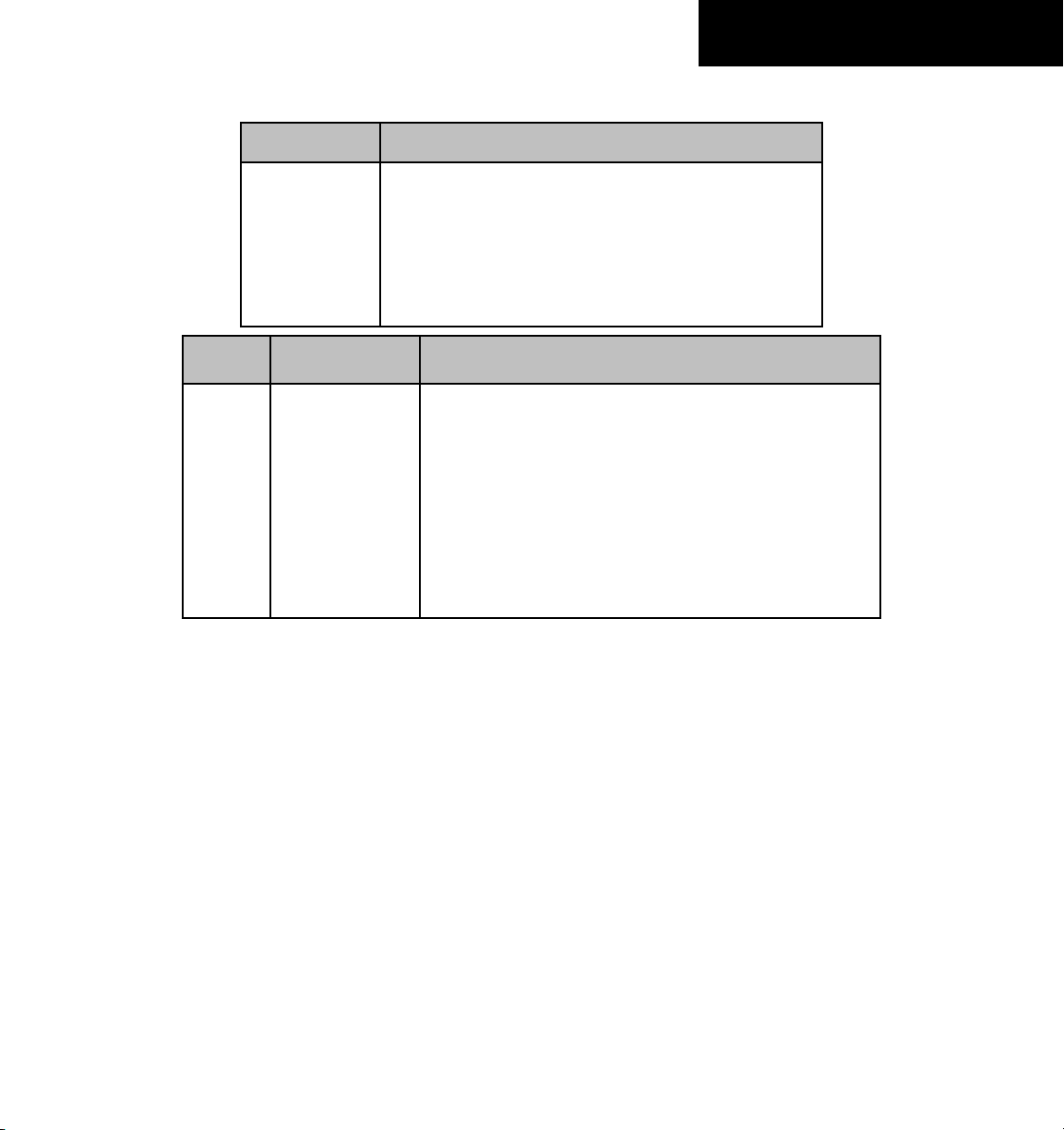
Part Number Change Summary
190-00140-00
Made various layout corrections, no content changes
(Rev. J)
Revision Date of Revision Description
A
B
C
D
E
F
G
H
12/98
4/99
6/99
7/99
4/00
7/00
5/03
5/06
Initial Release
Update to conform to recent SW changes
Added Addendum
Update for SW 2.10
Update for SW 2.15
Updated Power On, Wind Vector, Crossfill, DME, and Fuel Plan
Added FDE Section, updated per SW 5.01, misc. changes
Changed to 8 inch x 8.5 inch format. Added TERRAIN, misc.
changes
RECORD OF REVISIONS
GNS 430 Pilot’s Guide and Reference
i
Page 4

COPYRIGHT
Copyright © 1998-2006 Garmin Ltd. or its subsidiaries. All rights reserved.
This manual reflects the operation of Main System Software version 5.01 or later. Some differences may be observed when
comparing the information in this manual to other software versions.
Garmin International, Inc., 1200 East 151st Street, Olathe, Kansas 66062 USA
p: 913.397.8200 f: 913.397.8282
Garmin AT, Inc., 2345 Turner Road SE, Salem, Oregon 97302 USA
p: 503.391.3411 f: 503.364.2138
Garmin (Europe) Ltd., Unit 5, The Quadrangle, Abbey Park, Industrial Estate, Romsey, SO51 9DL, U.K.
p: 44/0870.8501241 f: 44/0870.85012
51
Garmin (Asia) Corp., No. 68, Jangshu 2nd Road., Shijr, Taipei County, Taiwan
p: 886/2.2642.9199 f : 886/2.2642-9099
Web Site Address: www.garmin.com
Visit the Garmin website for the latest updates and supplemental information concerning the operation of this and other Garmin
products.
Except as expressly provided herein, no part of this manual may be reproduced, copied, transmitted, disseminated, downloaded or
stored in any storage medium, for any purpose without the express written permission of Garmin. Garmin hereby grants permission
to download a single copy of this manual and of any revision to this manual onto a hard drive or other electronic storage medium to
be viewed for personal use, provided that such electronic or printed copy of this manual or revision must contain the complete text
of this copyright notice and provided further that any unauthorized commercial distribution of this manual or any revision hereto is
strictly prohibited.
Garmin®, AutoLocate®, and PhaseTrac12® are registered trademarks of Garmin Ltd. or its subsidiaries and may not be used
without the express permission of Garmin.
GNS™ and Spell’N’Find™ are trademarks of Garmin Ltd. or its subsidiaries and may not be used without the express permission of
Garmin.
NavData® is a registered trademark of Jeppesen, Inc.
June 2006 190-00140-00 Rev. J Printed in the U.S.A.
ii
GNS 430 Pilot’s Guide and Reference
Page 5

TABLE OF CONTENTS
SECTION 1: INTRODUCTION ........................................... 1-1
1.1 Accessories and Packing List ................................. 1-1
1.2 Key and Knob Functions ......................................... 1-2
1.3 Takeoff Tour ............................................................... 1-5
SECTION 2: COM .................................................................. 2-1
2.1 Communicating using the GNS 430 ...................... 2-1
SECTION 3: NAV PAGES .................................................. 3-1
3.1 Main Page Groups .................................................... 3-1
3.2 NAV Page Group ....................................................... 3-1
3.3 Default NAV Page .....................................................3-2
3.4 Map Page ...................................................................3-5
3.5 TERRAIN Page .......................................................... 3-14
3.6 NAV/COM Page ........................................................ 3-17
3.7 Position Page ..........................................................3-19
3.8 Satellite Status Page ............................................. 3-22
3.9 Vertical Navigation Page ...................................... 3-24
SECTION 4: DIRECT-TO NAVIGATION .........................4-1
4.1 Overview .................................................................... 4-1
SECTION 5: FLIGHT PLANS .............................................5-1
5.1 Flight Plan Catalog Page ........................................ 5-1
5.2 Active Flight Plan Page ........................................... 5-8
SECTION 6: PROCEDURES ............................................... 6-1
6.1 Approaches, Departures and Arrivals .................. 6-1
6.2 Non-Precision Approach Operations .................... 6-3
6.3 ILS Approaches ....................................................... 6-26
6.4 Points to Remember for All Approaches ..........6-32
SECTION 7: WPT PAGES .................................................... 7-1
7.1 WPT Page Group ....................................................... 7-1
7.2 Airport Location Page ............................................. 7-4
7.3 Airport Runway Page .............................................. 7-5
7.4 Airport Frequency Page .......................................... 7-6
7.5 Airport Approach Page ...........................................7-8
7.6 Airport Arrival Page ............................................... 7-11
7.7 Airport Departure Page ........................................ 7-13
7.8 Intersection Page ................................................... 7-14
7.9 NDB Page .................................................................. 7-15
7.10 VOR Page ................................................................7-15
7.11 User Waypoint Page ............................................7-17
SECTION 8: NRST PAGES ................................................. 8-1
8.1 NRST Page Group .....................................................8-1
8.2 Nearest Airport Page ............................................... 8-4
8.3 Nearest Intersection Page ...................................... 8-6
8.4 Nearest NDB Page .................................................... 8-6
8.5 Nearest VOR Page ....................................................8-6
8.6 Nearest User Waypoint Page ................................. 8-8
8.7 Nearest Center (ARTCC) Page ................................ 8-8
8.8 Nearest Flight Service Station (FSS) Page ..........8-9
8.9 Nearest Airspace Page .......................................... 8-10
SECTION 9: VLOC RECEIVER ........................................... 9-1
9.1 VLOC (VOR/LOCALIZER/GLIDESLOPE) Receiver
Operations ......................................................................... 9-1
SECTION 10: AUX PAGES ...............................................10-1
10.1 AUX Page Group ................................................... 10-1
10.2 Flight Planning Page ...........................................10-2
10.3 Utility Page ..........................................................10-12
10.4 Setup 1 Page ....................................................... 10-20
10.5 Setup 2 Page ....................................................... 10-27
SECTION 11: TERRAIN INTERFACE ............................ 11-1
11.1 Introduction ..........................................................11-1
11.2 TERRAIN Operation ..............................................11-2
11.3 TERRAIN Alerts ......................................................11-7
SECTION 12: FAULT DETECTION AND
EXCLUSION ............................................................................ 12-1
12.1 Detection and Exclusion ..................................... 12-1
12.2 Pre-Departure Verification of FDE ....................12-2
SECTION 13: MESSAGES, ABBREVIATIONS, AND
TERMS ............................................................................ 13-1
NAV
13.1 Messages ................................................................ 13-1
13.2 Abbreviations ........................................................13-9
13.3 Navigation Terms ...............................................13-12
Appendix A: Data Card Use ..........................................A-1
Appendix B: Specifications ........................................... B-1
Appendix C: Map Datums ..............................................C-1
Appendix D: Troubleshooting Q & A .......................D-1
GNS 430 Pilot’s Guide and Reference
iii
Page 6

WARNINGS,
CAUTIONS, AND NOTES
WARNING: Navigation and terrain separation must NOT be predicated upon the use of the TERRAIN function.
The TERRAIN feature is NOT intended to be used as a primary reference for terrain avoidance and does not
relieve the pilot from the responsibility of being aware of surroundings during flight. The TERRAIN feature is
only to be used as an aid for terrain avoidance and is not certified for use in applications requiring a certified
terrain awareness system. Terrain data is obtained from third party sources. Garmin is not able to independently
verify the accuracy of the terrain data.
WARNING: The terrain data should be used only as an aid for situational awareness. Terrain data must not
be used as the sole basis for decisions or maneuvers to avoid terrain or obstacles. Terrain data must not be
used for navigation.
WARNING: The altitude calculated by GNS 430 GPS receivers is geometric height above Mean Sea Level and
could vary significantly from the altitude displayed by pressure altimeters in aircraft. GPS altitude should never
be used for vertical navigation. Always use pressure altitude displayed by pressure altimeters in the aircraft.
WARNING: The Jeppesen database used in the GNS 430 system must be updated regularly in order to ensure
that its information remains current. Updates are released every 28 days. A database information packet is
included in the GNS 430 package. Pilots using an outdated database do so entirely at their own risk.
WARNING: The basemap (land and water data) must not be used for navigation, but rather only for nonnavigational situational awareness. Any basemap indication should be compared with other navigation
sources.
WARNING: For safety reasons, GNS 430 operational procedures must be learned on the ground.
WARNING: The United States government operates the Global Positioning System and is solely responsible
for its accuracy and maintenance. The GPS system is subject to changes which could affect the accuracy and
performance of all GPS equipment. GPS accuracy may be degraded by the U.S. Department of Defense-imposed
Selective Availability (SA) program. With ‘SA’ on, GPS altitude may be in error by several hundred feet. Portions
of the Garmin GNS 430 utilize GPS as a precision electronic NAVigation AID (NAVAID). Therefore, as with all
NAVAIDs, information presented by the GNS 430 can be misused or misinterpreted and, therefore, become
unsafe.
iv
GNS 430 Pilot’s Guide and Reference
Page 7
WARNINGS,
CAUTIONS, AND NOTES
WARNING: Use the GNS 430 at your own risk. To reduce the risk of unsafe operation, carefully review and
understand all aspects of the GNS 430 Pilot’s Guide documentation and the GNS 430 Flight Manual Supplement.
Thoroughly practice basic operation prior to actual use. During flight operations, carefully compare indications
from the GNS 430 to all available navigation sources, including the information from other NAVAIDs, visual
sightings, charts, etc. For safety purposes, always resolve any discrepancies before continuing navigation.
CAUTION: The GNS 430 display lens is coated with a special anti-reflective coating that is very sensitive to
skin oils, waxes, and abrasive cleaners. CLEANERS CONTAINING AMMONIA WILL HARM THE ANTI-REFLECTIVE
COATING. It is very important to clean the lens using a clean, lint-free cloth and an eyeglass lens cleaner that
is specified as safe for anti-reflective coatings.
CAUTION: The Garmin GNS 430 does not contain any user-serviceable parts. Repairs should only be made by
an authorized Garmin service center. Unauthorized repairs or modifications could void both the warranty and
the pilot’s authority to operate this device under FAA/FCC regulations.
NOTE: All visual depictions contained within this document, including screen images of the GNS 430 panel and
displays, are subject to change and may not reflect the most current GNS 430 system. Depictions of equipment
may differ slightly from the actual equipment.
NOTE: This device complies with part 15 of the FCC Rules. Operation is subject to the following two conditions:
(1) this device may not cause harmful interference, and (2) this device must accept any interference received,
including interference that may cause undesired operation.
NOTE: Unless otherwise specified within this manual, the term ‘GNS 430’ applies to both the GNS 430 and the
GNS 430A models. Please, note that the difference between these two models is indicated under ‘VHF COM
Performance’ in the Specifications section of this manual (Appendix B).
NOTE: This product, its packaging, and its components contain chemicals known to the State of California to
cause cancer, birth defects, or reproductive harm. This notice is being provided in accordance with California’s
Proposition 65. If you have any questions or would like additional information, please refer to our website at
www.garmin.com/prop65.
GNS 430 Pilot’s Guide and Reference
v
Page 8

WARRANTY
LIMITED WARRANTY
This Garmin product is warranted to be free from defects in materials or workmanship for two years from the date of purchase. Within
this period, Garmin will, at its sole option, repair or replace any components that fail in normal use. Such repairs or replacement will
be made at no charge to the customer for parts and labor, provided that the customer shall be responsible for any transportation cost.
This warranty does not cover failures due to abuse, misuse, accident, or unauthorized alterations or repairs.
THE WARRANTIES AND REMEDIES CONTAINED HEREIN ARE EXCLUSIVE AND IN LIEU OF ALL OTHER WARRANTIES EXPRESS OR
IMPLIED OR STATUTORY, INCLUDING ANY LIABILITY ARISING UNDER ANY WARRANTY OF MERCHANTABILITY OR FITNESS FOR
A PARTICULAR PURPOSE, STATUTORY OR OTHERWISE. THIS WARRANTY GIVES YOU SPECIFIC LEGAL RIGHTS, WHICH MAY VARY
FROM STATE TO STATE.
IN NO EVENT SHALL GARMIN BE LIABLE FOR ANY INCIDENTAL, SPECIAL, INDIRECT OR CONSEQUENTIAL DAMAGES, WHETHER
RESULTING FROM THE USE, MISUSE, OR INABILITY TO USE THIS PRODUCT OR FROM DEFECTS IN THE PRODUCT. Some states do not
allow the exclusion of incidental or consequential damages, so the above limitations may not apply to you.
Garmin retains the exclusive right to repair or replace the unit or software, or to offer a full refund of the purchase price, at its sole
discretion. SUCH REMEDY SHALL BE YOUR SOLE AND EXCLUSIVE REMEDY FOR ANY BREACH OF WARRANTY.
To obtain warranty service, contact your local Garmin Authorized Service Center. For assistance in locating a Service Center near you,
visit the Garmin Web site at “http://www.garmin.com” or contact Garmin Customer Service at 800-800-1020.
vi
GNS 430 Pilot’s Guide and Reference
Page 9

SECTION 1
INTRODUCTION
SECTION 1: INTRODUCTION
1.1 ACCESSORIES AND PACKING LIST
Congratulations on choosing the finest, most advanced
panel mount IFR navigation/communication system
available. The GNS 430 represents Garmin’s commitment
to provide accurate, easy-to-use avionics.
Before installing and getting started with the GNS 430,
please check to see that the package includes the following
items. If any parts are missing or damaged, please contact
a Garmin dealer immediately.
Standard Package:
• GNS 430 Unit, NavData® Card, and Terrain Data
Card
• Installation Rack, Connectors, and GPS Antenna
• Pilot’s Guide and Quick Reference Guide
• 400/500 Series Display Interface Pilot’s Guide
Addendum
The Garmin dealer performs the installation and
configuration of the GNS 430. The GNS 430 is secured
in the installation rack with the proper wiring connections
performed. After installation, the NavData card and the
Terrain Data card (if applicable) are installed into the
correct slot on the front of the unit (Appendix A). A
Garmin dealer can answer questions about the installation
such as location of antennas or any connections to other
equipment in the panel.
NOTE: Help Garmin provide better support by
completing our on-line registration. Registration
ensures notification of product updates, new
products, and provides for lost or stolen unit
tracking. Have the serial number of the GNS
430 available and connect to our website (www.
garmin.com). Look for the product registration
link on the home page.
• Database Subscription Packet
• Warranty Registration Card
• GNS 430 Simulator CD-ROM
GNS 430 Pilot’s Guide and Reference
1-1
Page 10
SECTION 1
INTRODUCTION
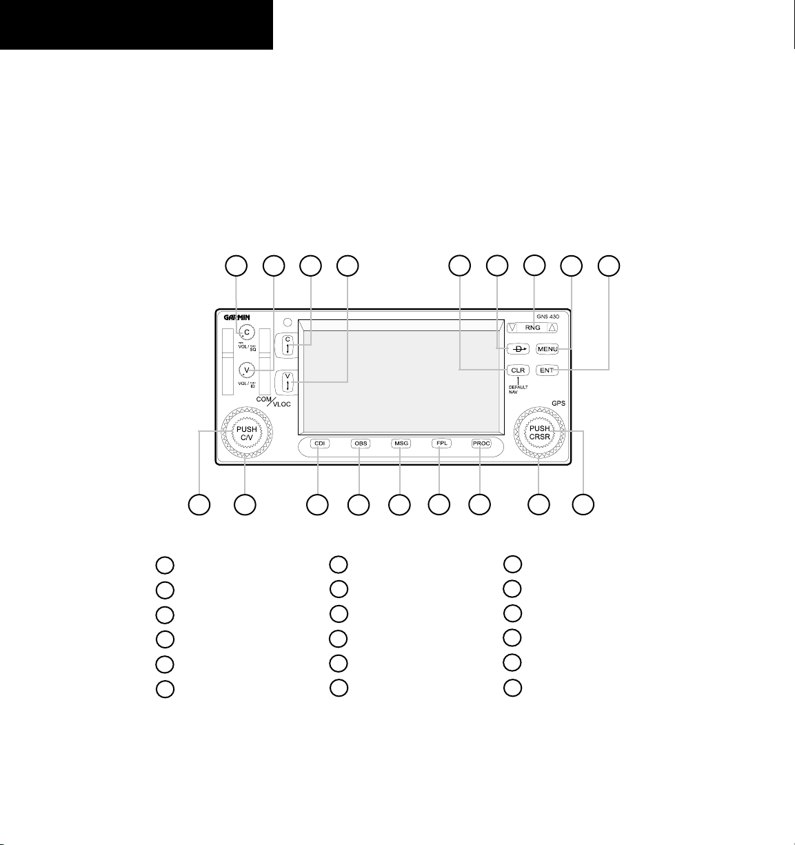
1.2 KEY AND KNOB FUNCTIONS
The GNS 430 is designed to make operation as simple
as possible. The key and knob descriptions (Figure
1-1) provide a general overview of the primary function(s)
for each key and knob. The takeoff tour (Section 1.3)
is intended to provide a brief overview of the primary
functions of the GNS 430.
2
1
4
Experiment with the unit and refer to the reference
sections for more information.
Data is entered using the large and small knobs.
Experiment with them to become efficient at entering data.
This greatly reduces the amount of time spent operating
the GNS 430 in flight.
5
7
63
9
8
1-2
10
COM Power/Volume
1
VLOC Volume
2
3
COM Flip-flop
4
VLOC Flip-flop
5
CLR (clear)
Direct-to
6
11 12
13 14
Figure 1-1 Keys and Knobs
7
RNG (map range)
8
MENU
9
ENT (enter)
10
Small left knob
11
Large left knob Large right knob
12
CDI
GNS 430 Pilot’s Guide and Reference
15 16
17
13
OBS
14
MSG (message)
15
FPL (flight plan)
16
PROC (procedures)
17
18
Small right knob
18
Page 11

SECTION 1
INTRODUCTION
Left-hand Keys and Knobs
The COM Power/Volume Knob controls unit power
and communications radio volume. Press momentarily to
disable automatic squelch control.
The VLOC Volume Knob controls audio volume for
the selected VOR/Localizer frequency. Press momentarily
to enable/disable the ident tone.
The large left knob (COM/VLOC) is used to tune the
megahertz (MHz) value of the standby frequency for the
communications transceiver (COM) or the VLOC receiver,
whichever is currently selected by the tuning cursor.
The small left knob (COM/VLOC) is used to tune
the kilohertz (kHz) value of the standby frequency for
the communications transceiver (COM) or the VLOC
receiver, whichever is currently selected by the tuning
cursor. Press this knob momentarily to toggle the
cursor between the COM and VLOC frequency fields.
The COM Flip-flop Key is used to swap the active
and standby COM frequencies. Press and hold to select
emergency channel (121.500 MHz).
The VLOC Flip-flop Key is used to swap the active
and standby VLOC frequencies (i.e., make the selected
standby frequency active).
tuning
Right-hand Keys and Knobs
The RNG Key allows the pilot to select the desired
map range. Use the up arrow to zoom out to a larger area,
or the down arrow to zoom in to a smaller area.
The Direct-to Key provides access to the direct-to
function, which allows the pilot to enter a destination
waypoint and establishes a direct course to the selected
destination (Section 4).
The MENU Key displays a context-sensitive list of
options. This options list allows the pilot to access
additional features or make settings changes which relate
to the currently displayed page.
The CLR Key is used to erase information, remove
map detail, or to cancel an entry. Press and hold the CLR
key to immediately display the Default NAV Page.
The ENT Key is used to approve an operation or
complete data entry. It is also used to confirm information,
such as during power on.
The large right knob is used to select between the
various page groups: NAV, WPT, AUX, or NRST. With
the on-screen cursor enabled, the large
the pilot to move the cursor about the page. The large
right knob is also used to move the target pointer right
(turn clockwise) or left (counterclockwise) when the map
panning function is active.
The small right knob is used to select between the
various pages within one of the groups listed above. Press
this knob momentarily to display the on-screen cursor.
The cursor allows the pilot to enter data and/or make a
selection from a list of options. When entering data, the
small knob is used to select the desired letter or number
and the large knob is used to move to the next character
space. The small right knob is also used to move the target
pointer up (turn clockwise) or down (counterclockwise)
when the map panning function is active.
right knob allows
GNS 430 Pilot’s Guide and Reference
1-3
Page 12
SECTION 1
INTRODUCTION
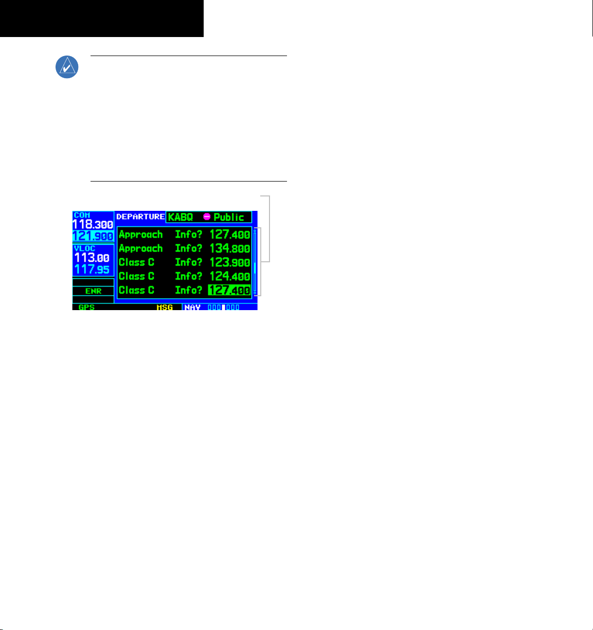
NOTE: When the GNS 430 is displaying a list
of information that is too long for the display
screen, a scroll bar appears along the right-hand
side of the display (Figure 1-2). The scroll bar
graphically indicates the number of additional
items available within the selected category. To
scroll through the list, press the small right knob
to activate the cursor, then turn the large right
knob.
Scroll Bar
Figure 1-2 Scroll Bar
Bottom Row Keys
The CDI Key is used to toggle which navigation source
(GPS or VLOC) provides output to an external HSI or
CDI.
The OBS Key is used to select manual or automatic
sequencing of waypoints. Pressing the
OBS mode, which retains the current ‘active to’ waypoint
as the navigation reference even after passing the waypoint
(i.e., prevents sequencing to the next waypoint). Pressing
the OBS Key again returns the unit to normal operation,
with automatic sequencing of waypoints. When OBS
mode is selected, the pilot may set the desired course
to/from a waypoint using the
pop-up window
, or an external OBS selector on the HSI
or CDI.
The MSG Key is used to view system messages and to
alert the pilot to important warnings and requirements.
See Section 13.1 for more information on messages.
The FPL Key allows the pilot to create, edit, activate,
and invert flight plans, as well as access approaches,
departures, and arrivals. A closest point to flight plan
feature is also available from the FPL Key. See Section 5
for more information on flight plans.
The PROC Key allows the pilot to select and remove
approaches, departures, and arrivals from the flight plan.
When using a flight plan, available procedures for the
departure and/or arrival airport are offered automatically.
Otherwise, the pilot may select the desired airport, then
the desired procedure.
OBS Key selects
‘Select OBS Course’
1-4
GNS 430 Pilot’s Guide and Reference
Page 13

SECTION 1
INTRODUCTION
1.3 TAKEOFF TOUR
reading within this Pilot’s Guide includes:
Overview
The Garmin GNS 430 provides the pilot accurate
navigational data and communication capability, along
with non-precision and precision approach certification
in the IFR environment. The takeoff tour is designed to
familiarize the pilot with the operation of the GNS 430
by :
• Powering up the unit
• Changing frequencies
• Entering data
• Performing a simple direct-to
• Selecting IFR procedures
• Using some limited flight plans
In addition, this section briefly covers the Default NAV
Page, the Map Page, and the NAV/COM Page, which are
available as part of the NAV Page Group. These pages are
used for most of the in-flight navigation.
The takeoff tour assumes that the unit and antennas
have been properly installed and that the GNS 430’s
default settings have not been changed. If any of the
factory default settings (position format, units of measure,
selectable fields, etc.) have been changed, the pictures
shown here may not exactly match what is shown on
the GNS 430. Prior to using the GNS 430 for the first
time, Garmin recommends that the aircraft be moved to a
location that is well away from buildings and other aircraft
so the unit can collect satellite data without interruption.
This takeoff tour is intended to provide a brief
introduction of the GNS 430’s major features. Sections
2 through 13 of this manual describe these features, and
others, in additional detail. Refer to these sections, as
needed, to learn or review the details regarding a particular
feature.
Service staff is available during normal business hours
(U.S. Central time zone) at the phone and fax numbers
listed on page ii. Garmin can also be reached by mail
(page ii) or at our web site address, www.garmin.com.
Powering up the GNS 430
using the COM Power/Volume knob at the top left corner
of the unit. Turning it clockwise turns unit power on and
increases the COM radio volume. After turning the unit
on, a welcome page (Figure 1-3) is displayed while the
unit performs a self test, followed sequentially by the Land
Data Page, then (if configured for TERRAIN) the Terrain
Data Page, the Obstacle Data Page, and the Airport Terrain
Data Page.
After becoming familiar with the basics, some suggested
• Flight plan features - Section 5
• Waypoint information pages (database
information) - Section 7
• IFR procedures - Section 6
• Unit settings (configuring the unit to the pilot’s
preferences) - Section 10
If more information is needed, Garmin’s Customer
The GNS 430’s power and COM volume are controlled
Figure 1-3 Welcome Page
GNS 430 Pilot’s Guide and Reference
1-5
Page 14
SECTION 1
INTRODUCTION
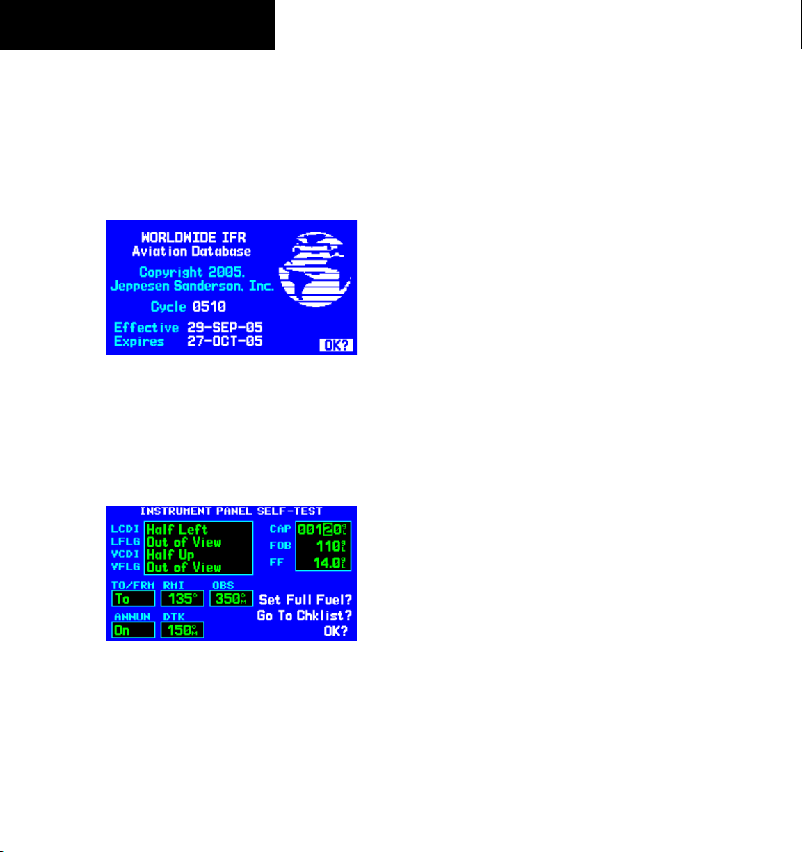
The Database Confirmation Page (Figure 1-4) appears
next, which shows the current database information on
the NavData card (with the valid operating dates, cycle
number, and database type indicated). The database is
updated every 28 days, and must be current for approved
instrument approach operations. Information on database
subscriptions is available inside the GNS 430 package.
Figure 1-4 Database Confirmation Page
To acknowledge the database information:
Press the
ENT Key.
Once the database has been acknowledged, the
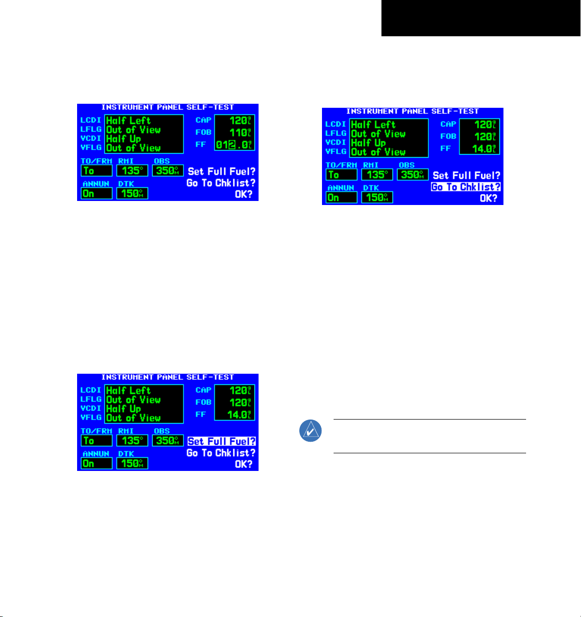
Instrument Panel Self-test Page appears (Figure 1-5).
Instrument Panel Self-test Page
To ensure that the GNS 430 and any connected
instruments are working properly, check for the following
indications on the CDI/HSI, RMI, external annunciators,
and other connected instruments:
• Course deviation - Half left/no flag
• TO/FROM flag - TO
• Bearing to destination - 135°
• Distance to dest. - 10.0 nautical mile (nm)
• All external annunciators (if installed) - On
• Glideslope - Half up/no flag
• Time to destination - 4 minutes
• Desired
• Ground speed - 150 knots
The Instrument Panel Self-test Page (Figure 1-5)
indicates the currently selected OBS course, fuel capacity
(CAP), fuel on board (FOB), and fuel flow (FF). The fuel
capacity, fuel on board, and fuel flow may be manually
entered if the installation does not include connection to
sensors which automatically provide these figures.
track - 149.5°
1-6
Figure 1-5 Instrument Panel Self-Test Page
GNS 430 Pilot’s Guide and Reference
To enter fuel capacity, fuel on board or fuel
flow figures (if not provided by sensors):
1) Turn the large
right knob to select the ‘CAP’,
‘FOB’, or ‘FF’ field.
Page 15
SECTION 1
INTRODUCTION
2) Turn the small and large right knobs to enter
the desired figure (Figures 1-5 and 1-6) and
press the ENT Key.
Figure 1-6 Fuel Flow Selected
The Instrument Panel Self-test Page includes selections
to set fuel on board (FOB) to full capacity and access the
Checklists Page. This allows the pilot to quickly set fuel
to full limits and display any checklists that have been
entered, such as start up or takeoff checklists.
To set fuel on board to full (if not provided
by sensor):
1) Turn the large
right knob to highlight ‘Set Full
Fuel?’ (Figure 1-7).
To view the Checklists Page:
1) Turn the large
right knob to highlight ‘Go To
Chklist?’ (Figure 1-8) and press the ENT Key.
Figure 1-8 ‘Go To Chklist?’ Highlighted
2) Turn the large right knob to select the desired
checklist, then execute each step (Section
10.3, Utility Page: Checklists) in the selected
checklist.
3) Once the pilot completes the desired checklist(s),
press the small
right knob to return to the
Checklists Page. Press the small right knob
again to return to normal operation on the
Satellite Status Page or the Map Page.
Figure 1-7 ‘Set Full Fuel?’ Highlighted
2) Press the ENT Key and verify that fuel on board
(‘FOB’) now matches the fuel capacity (CAP)
figure. Fuel on board is reduced, over time,
based on the fuel flow (FF) figure.
GNS 430 Pilot’s Guide and Reference
4) Once instrument operation has been verified
with the Instrument Panel Self-test Page
displayed, press the
NOTE: The GNS 430 can hold up to nine checklists
with up to 30 entries in each checklist.
ENT Key.
1-7
Page 16
SECTION 1
INTRODUCTION
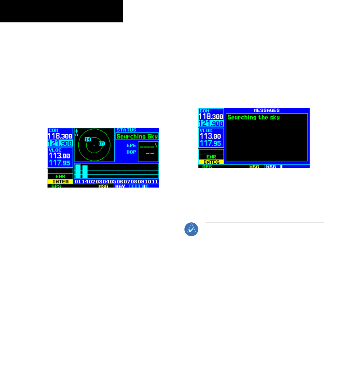
Satellite Status Page
The Satellite Status Page (Figure 1-9) appears as the
GNS 430 attempts to collect satellite information.
When an ‘Acquiring’ status is displayed on the Satellite
Status Page, the signal strengths of any satellites received
appear as ‘bar graph’ readings. This is a good indication
that the unit is receiving signals and a position fix is being
determined. Following the first-time use of the GNS 430,
the time required for a position fix varies, usually from
one to two minutes.
Figure 1-9 Satellite Status Page
If the unit can only obtain enough satellites for 2D
navigation (no altitude), the unit uses the altitude provided
by the altitude encoder (if one is connected).
The ‘INTEG’ annunciator (bottom left corner of the
screen) indicates that satellite coverage is insufficient to
pass built-in integrity monitoring tests. In the example
above, not enough satellites are being received to determine
a position. The Satellite Status Page shows the ID numbers
for the satellites and the relative signal strength of each
satellite received (as a ‘bar graph’ reading).
‘Searching Sky’ indicates that satellite almanac data is
not available or has expired (if the unit hasn’t been used
for six months or more). This means the unit is acquiring
satellite data to establish almanac and satellite orbit
information, which can take five to ten minutes. The data
is recollected from the first available satellite. The Satellite
Status Page displays a ‘Search Sky’ status, and the message
annunciator (MSG), above the MSG Key also flashes to
alert the pilot of system message, ‘Searching the Sky’.
To view a system message:
Press the
MSG Key (Figure 1-10).
The Message Page appears and displays the status or
warning information applicable to the receiver’s current
operating condition.
Figure 1-10 Message Page
To return to the previous page after
viewing a message:
Press the
NOTE: The GNS 430 utilizes certain software
algorithms to ensure reliable GPS receiver
operation. Receiver Autonomous Integrity
Monitoring (RAIM) and Fault Detection and
Exclusion (FDE) are two examples. These features
allow navigation during Oceanic/Remote legs of
a flight using the GNS 430. For further details,
please refer to Sections 10.3 and 12.
MSG Key again.
1-8
GNS 430 Pilot’s Guide and Reference
Page 17
SECTION 1
INTRODUCTION
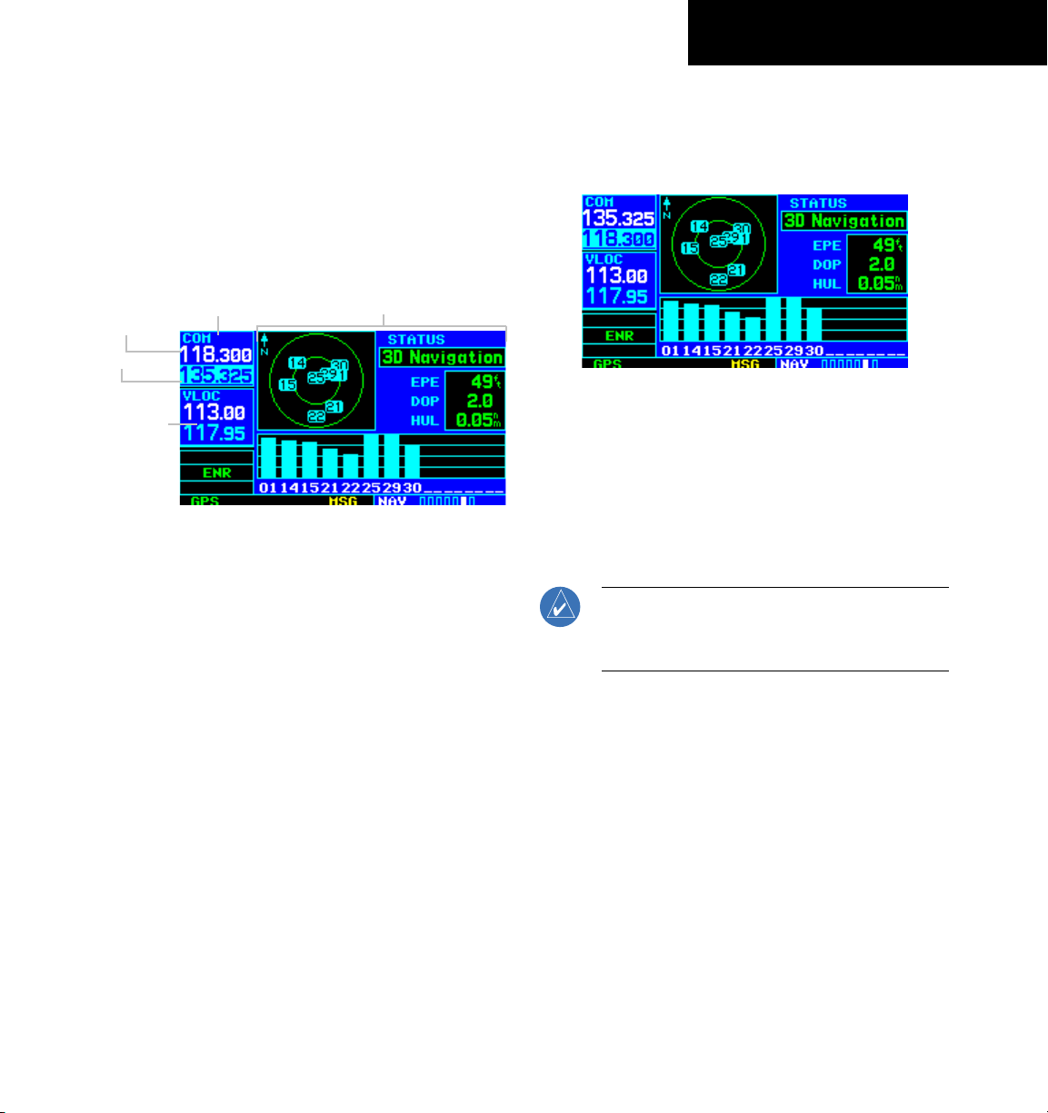
Selecting COM and VLOC Frequencies
While the GNS 430 is acquiring a position, take a
minute to dial in the active and standby frequencies to
be used for the first phase of the flight. The GNS 430’s
display is divided into separate ‘windows’ (or screen
areas), including a COM Window, VLOC Window, and
the GPS Window (Figure 1-11).
COM Window;
Active Frequency
Standby Frequency
VLOC
Window
Figure 1-11 Standby Frequency 135.325 MHz
Pressing the small left knob activates the tuning cursor in the desired frequency window. To select the active
frequency, first enter the frequency in the standby field,
and use the COM Flip-flop (or the NAV Flip-flop) Key
to move it to the active field.
To change the standby communication
frequency:
1) Press the small
left knob if needed, to move
the tuning cursor to the COM Window (Figure
1-11).
2) Turn the large
left knob to select the MHz,
and the small left knob to select the kHz of
the desired frequency.
GPS Window
To place the standby communication
frequency in the active field:
Press the COM Flip-flop Key
Figure 1-12 Active Frequency 135.325 MHz
(Figure 1-12).
Once the active frequency has been entered, repeat
steps 1 and 2 to enter the standby frequency. After both
communication frequencies have been entered, the COM
Window may be kept ‘hot’ by leaving the cursor on the
standby frequency. Move the cursor to the VLOC Window
by pressing the small left knob.
NOTE: When selecting VLOC frequencies, the
tuning cursor automatically returns to the COM
Window after 30 seconds of inactivity.
To change the standby VLOC frequency:
1) Press the small left knob if needed, to activate
the tuning cursor in the VLOC Window.
2) Turn the large
left knob to select the MHz,
and the small left knob to select the kHz of
the desired frequency.
To place the standby frequency in the
active field:
Press the NAV Flip-flop Key.
GNS 430 Pilot’s Guide and Reference
1-9
Page 18
SECTION 1
INTRODUCTION
Page Groups
Page Groups
NAV Group WPT Group AUX Group NRST Group
see Section 3 see Section 7 see Section 10 see Section 8
Table 1-1 Page Groups
The bottom right corner of the screen (Figure 1-13)
indicates which page group (Table 1-1) is currently being
displayed, the number of pages available within that group
(indicated by square icons), and the placement of the
current page within that group (indicated by a highlighted
square icon).
In addition to the NAV Page Group, additional page groups
are available for waypoint information (WPT), auxiliary
(AUX) functions such as flight planning or unit settings, and
listings for nearest (NRST) airports or other facilities.
NAV Pages
There are seven pages available under the NAV Page
Group*:
• Default NAV Page
• Map Page
• TERRAIN Page
• NAV/COM Page
• Position Page
• Satellite Status Page
• Vertical Navigation Page
The Default NAV Page, the Map Page, and the NAV/
COM Page are used for most of the in-flight navigation.
NOTE: *Eight NAV pages are available when
the GNS 430 installation includes connection
to traffic and/or weather information sources.
See the 400/500 Series Display Interfaces Pilot’s
Guide Addendum, p/n 190-00140-10, or the
400/500 Series Garmin Optional Displays Pilot’s
Guide Addendum, p/n 190-00140-13.
1-10
Position of
Current Page
within Current
Current Page Group
Figure 1-13 Current Page and Page Group
Number of Pages in
Current Page Group
Page Group
To select the desired page group:
Turn the large right knob until a page from the
desired page group is displayed (Figure 1-13).
To select the desired page within the page
group:
Turn the small right knob until the desired page
is displayed (Figure 1-13).
GNS 430 Pilot’s Guide and Reference
To select the NAV Page Group and display
the Default NAV Page:
Press and hold the
CLR Key.
To select the desired NAV Page:
Turn the small right knob until the desired
page is displayed.
Page 19
SECTION 1
INTRODUCTION
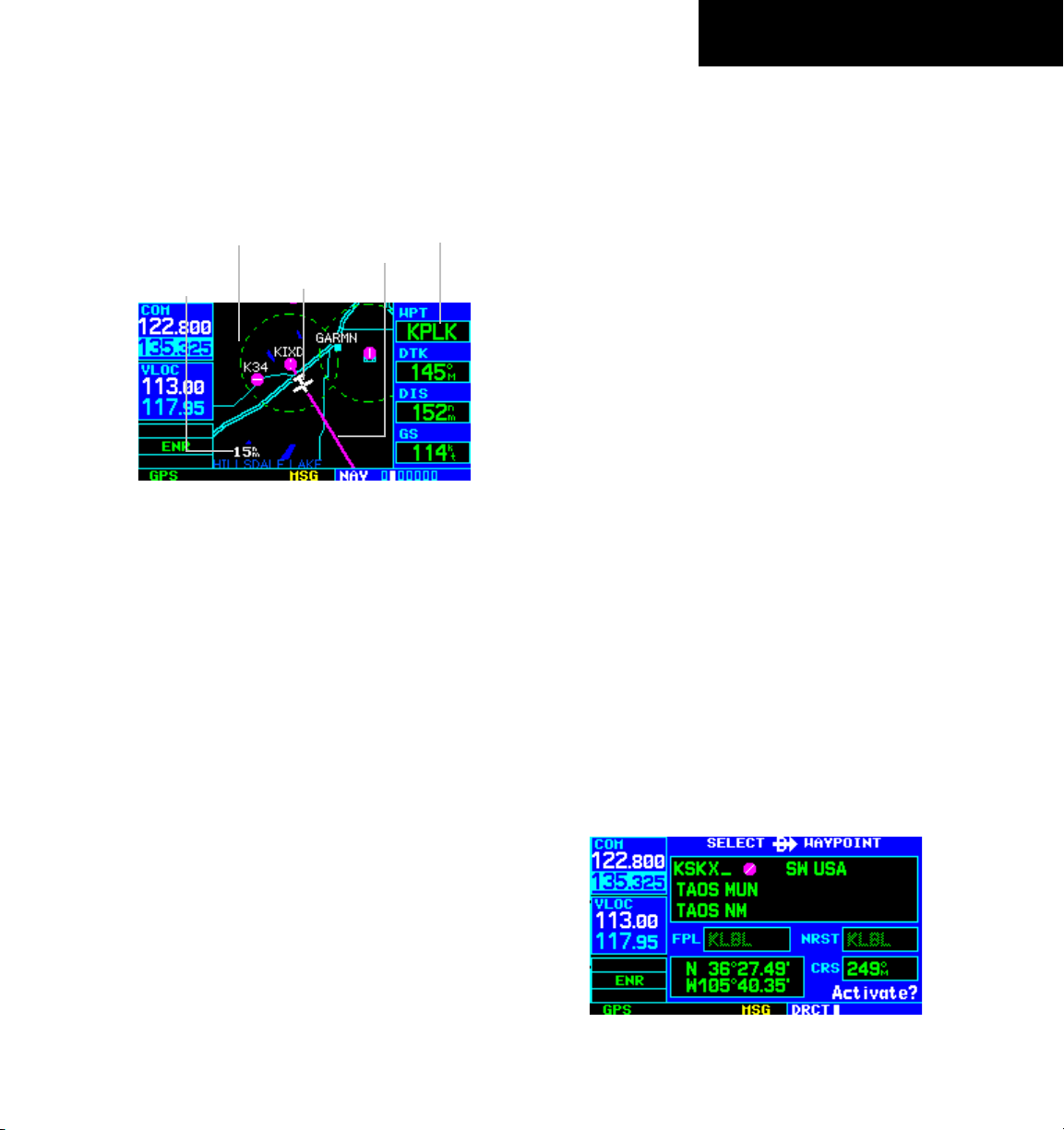
Map Page
After the GNS 430 acquires satellites and computes
a position, the Map Page (Figure 1-14) appears
automatically.
Map Display
Desired Track
Map Range
Present Position
Figure 1-14 Map Page
The Map Page displays the present position (using an
airplane symbol) relative to nearby airports, VORs, NDBs,
intersections, user waypoints, and airspace boundaries.
The route is displayed as a solid line.
Data fields for destination waypoint (WPT), distance
to waypoint (DIS), desired track (DTK), and ground speed
(GS) appear on the right-hand side of the display. These
fields are user selectable (Section 3.4, Selecting Desired
On-screen Data) to allow the pilot to configure the unit.
Available settings include: altitude, bearing, enroute safe
altitude, estimated time of arrival, minimum safe altitude,
and ground track.
A Map Setup Page is provided to designate the
maximum range at which each map feature appears.
These settings provide an automatic decluttering of the
map (based upon preferences) while adjusting the range.
See Section 13.3 for definitions of these navigation terms.
While viewing the Map Page, the pilot can quickly
declutter and remove many of the background map details
by pressing the CLR Key (repeatedly) until the desired
detail is depicted.
Data Fields
To change the map range, press the up arrow (to zoom
out) or the down arrow (to zoom in) of the
RNG (map
range) Key. The current map range is depicted in the
lower left corner of the Map Display.
Direct-to Navigation
The GNS 430 can use direct point-to-point navigation
to provide guidance from takeoff to touchdown, even
in the IFR environment. Once a destination is selected,
the unit provides speed, course, and distance data based
upon a direct course from the present position to the
destination. A destination can be selected from any page
with the Direct-to Key.
To select a direct-to destination:
1) Press the Direct-to Key. The Select Direct-to
Waypoint Page appears with the destination
field highlighted.
2) Turn the small
letter of the destination waypoint identifier.
The destination waypoint may be an airport,
VOR, NDB, intersection, or user waypoint,
as long as it is in the database or stored in
memory as a user waypoint.
3) Turn the large
the cursor to the next character position.
4) Repeat steps 2 and 3 to spell out the rest of
the waypoint identifier (Figure 1-15).
Figure 1-15 Direct-to Waypoint Page
right knob to enter the first
right knob to the right to move
GNS 430 Pilot’s Guide and Reference
1-11
Page 20
SECTION 1
INTRODUCTION
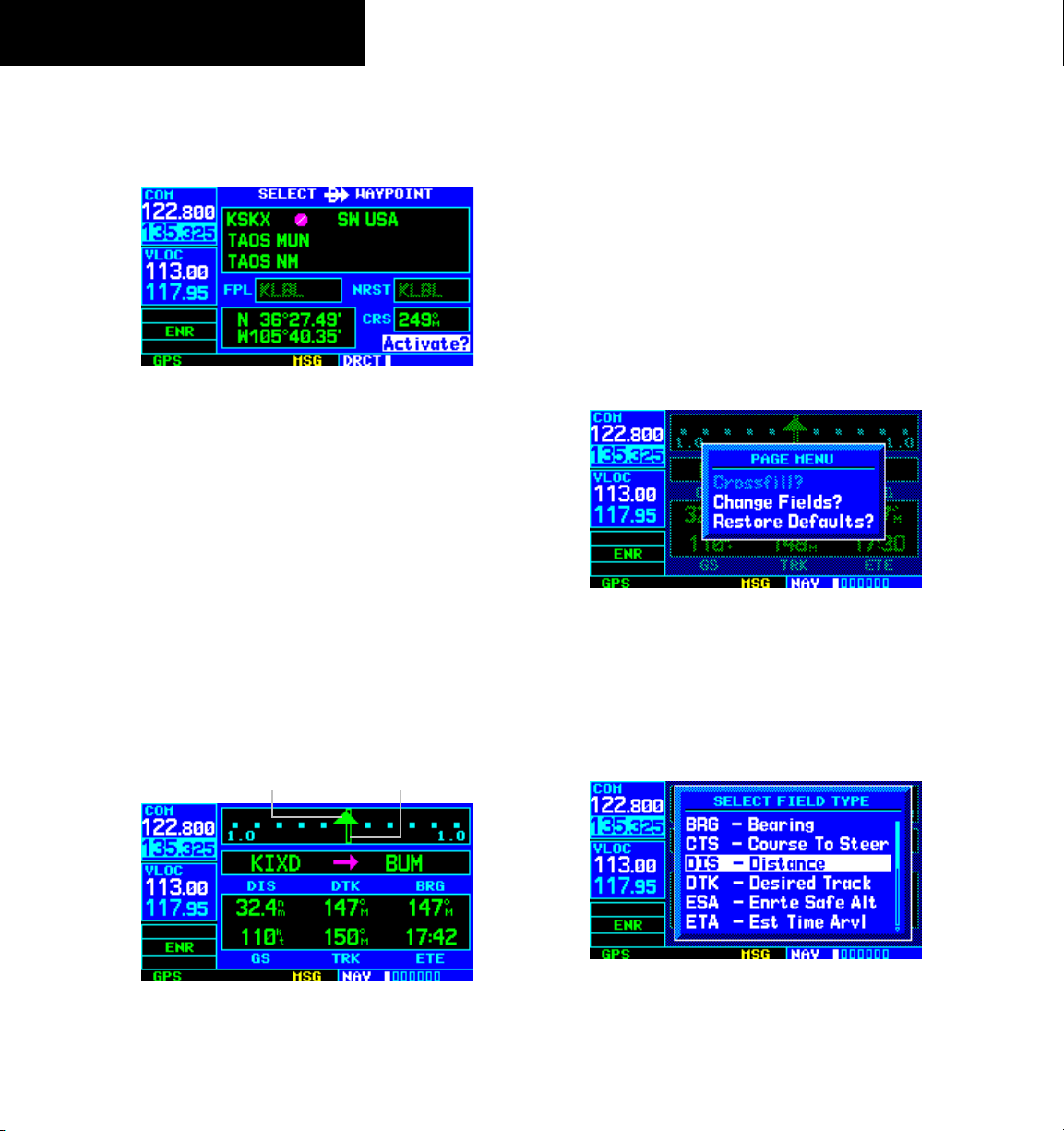
5) Press the ENT Key to confirm the identifier. The
‘Activate?’ function field is highlighted (Figure
1-16).
Figure 1-16 ‘Activate?’ Highlighted
6) Press the ENT Key to activate a direct-to course
to the selected destination.
Once a direct-to destination is selected, press and hold
the CLR Key to display the Default NAV Page.
Default NAV Page
During most flights, the Default NAV Page, the Map
Page, and the NAV/COM Page are the primary pages used
for navigation.
To select the Default NAV Page:
Pres s and ho ld the C LR Key (Fi gure
1-17).
TO/FROM Flag
Course Deviation
Indicator (CDI)
The Default NAV Page (Figure 1-17) displays a graphic
course deviation indicator (CDI), the active leg of the flight
plan (as defined by the current ‘from’ and ‘to’ waypoints),
and six user-selectable data fields. The default settings for
these fields are distance to waypoint (DIS), desired track
(DTK), bearing to waypoint (BRG), ground speed (GS),
ground track (TRK), and estimated time enroute (ETE).
See Section 13.3 for definitions of these navigation terms.
To change the data fields:
1) From the Default NAV page, press the MENU
Key and select ‘Change Fields?’ (Figure 1-18).
Figure 1-18 Default NAV Page Menu
2) Turn the large right knob to select the data
field to be changed.
3) Turn the small
right knob to display a list of
data options (Figure 1-19).
1-12
Figure 1-19 ‘Select Field Type’ Window
Figure 1-17 Default NAV Page
4) Press the ENT Key to select the desired data
item and return to the Default NAV Page.
GNS 430 Pilot’s Guide and Reference
Page 21
SECTION 1
INTRODUCTION
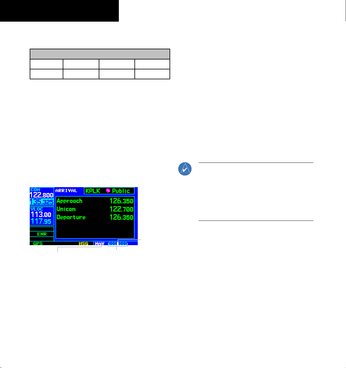
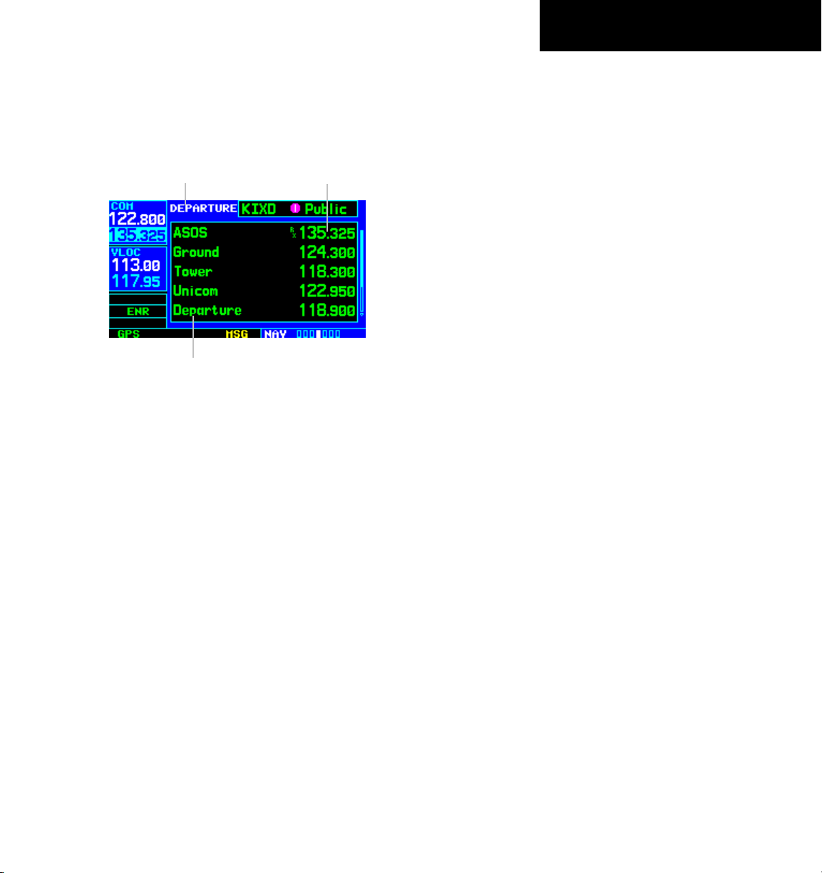
NAV/COM Page
From the Default NAV Page, turn the small right knob
until the NAV/COM Page (Figure 1-20) is displayed.
Departure, Enroute, or
Arrival Airport
Frequency Type
Figure 1-20 NAV/COM Page
The NAV/COM Page displays the available frequencies
(communications and navigation) for the departure airport,
any enroute airports which are included in the flight plan,
and the final destination airport. When using the directto function, frequencies are listed for the airport nearest to
the starting position and the destination airport.
Frequency List
A frequency listed on the NAV/COM Page can be
quickly transferred to the standby field of the COM
Window or the VLOC Window. This time-saving process
prevents having to ‘re-key’ a frequency already displayed
elsewhere on the screen.
To select a communication or navigation
frequency:
1) Press the small right knob to activate the
cursor in the GPS Window.
2) Turn the large
right knob to select the desired
frequency from the list.
3) Press the ENT Key to transfer the selected
frequency to the standby field in the COM or
VLOC Window. COM frequencies automatically
go to the standby field of the COM Window and
navigation frequencies automatically go to the
standby field of the VLOC Window, regardless
of which window is currently highlighted by
the cursor.
4) To activate the selected frequency, press the
COM or VLOC Flip-flop Key.
To display the frequency list for the desired
flight plan or direct-to airport:
1) Press the small right knob to activate the
cursor on the airport identifier field (in the GPS
Window).
2) Turn the small
right knob to display the list
of airports (departure, arrival, and enroute) for
the flight plan or direct-to. Continue to turn
the small right knob until the desired airport
is selected.
3) Press the
ENT Key to display the frequency list
for the selected airport.
GNS 430 Pilot’s Guide and Reference
1-13
Page 22
SECTION 1
INTRODUCTION
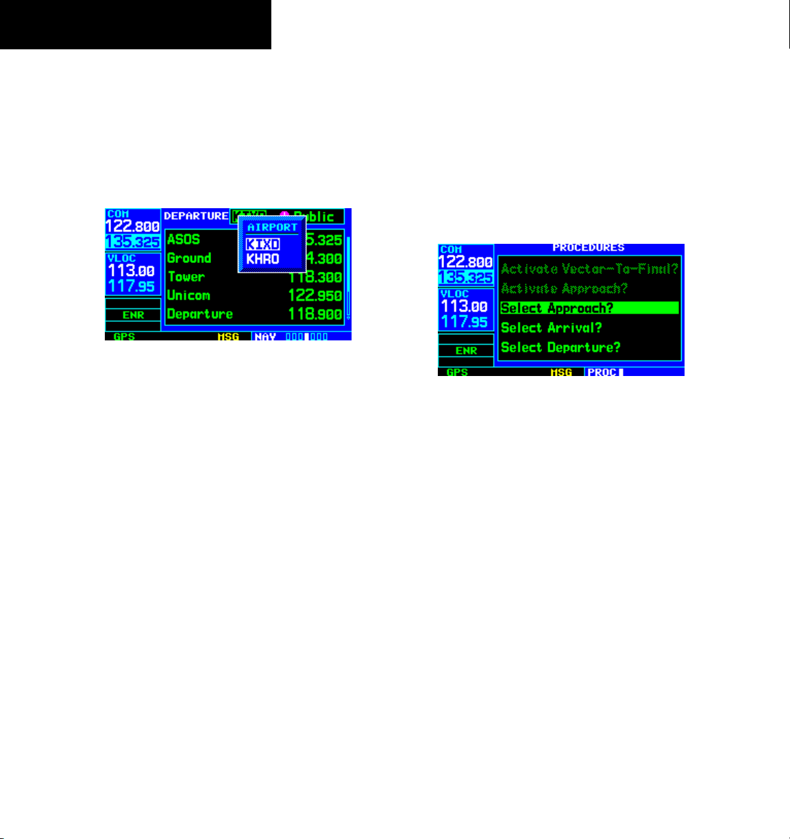
To display frequencies for a different
airport along the flight plan.
1) Press the small right knob to highlight the
airport identifier field.
2) Turn the small
right knob to display the list of
airports within the flight plan (Figure 1-21).
Figure 1-21 Airport Window
3) Continue turning the small right knob to select
the desired airport and press the ENT Key.
IFR Procedures
Once the direct-to or flight plan is confirmed, the whole
range of instrument procedures is available. Departures
(SIDs), arrivals (STARs), non-precision and precision
approaches are stored within the NavData card and are
available using the PROC (procedures) Key.
To display the Procedures Page (Figure 1-22), press the
PROC Key.
Figure 1-22 Procedures Page
The steps required to select and activate an approach,
departure, or arrival are identical. In this introductory
section, there are examples of the steps required to select
an approach, but keep in mind the same process also
applies to departures and arrivals.
1-14
To select an approach, departure, or arrival:
1) Turn the large
option (‘Select Approach?’, ‘Select Arrival?’,
or ‘Select Departure?’) from the Procedures
Page.
2) Press the ENT Key to display a list of
available procedures for the arrival (when using
approaches or STARs) or departure (when using
SIDs) airport.
3) Turn the small right knob to select the desired
procedure and press the ENT Key.
GNS 430 Pilot’s Guide and Reference
right knob to select the desired
Page 23
SECTION 1
INTRODUCTION
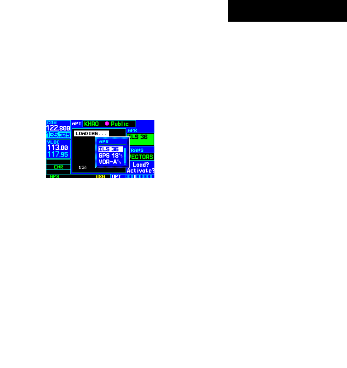
4) For approaches, a window appears (Figure
1-23) to select the desired initial approach
fix (IAF) or provide a ‘vectors’ option to select
just the final course segment of the approach.
Turn the small right knob to select the desired
option and press the ENT Key. (The ‘vectors’
option extends the final inbound course beyond
the final approach fix, allowing the pilot to
intercept the final course segment beyond its
normal limits.)
Figure 1-23 Approach Window
5) For departures and arrivals, a window appears
to select the desired transition. Turn the small
right knob to select the desired option and
press the ENT Key.
In the flight plan or direct-to, the departure or arrival
airport is replaced with the sequence of waypoints
contained within the selected procedure.
Nearest (NRST) Pages
The NRST Page Group provides detailed information
on the nine nearest airports, VORs, NDBs, intersections,
and user-created waypoints within 200 nm of the current
position. In addition, pages are also provided to display
the five nearest center (ARTCC/FIR) and Flight Service
Station (FSS) points of communication, plus alert the
pilot to any nearby special-use or controlled airspaces.
The Nearest Airport Page (Figure 1-24) is one of eight
pages available in the NRST group:
• Nearest Airport Page
• Nearest NDB Page
• Nearest User Waypoints Page
• Nearest FSS Page
• Nearest Intersection Page
• Nearest VOR Page
• Nearest ARTCC Page
• Nearest Airspace Page
The communication frequencies and
information may both be examined directly from the
Nearest Airport Page. As discussed earlier for the NAV/
COM Page, the pilot may also place any displayed
frequency into the standby COM or VLOC field by
highlighting the frequency with the cursor and pressing
the ENT Key.
runway
GNS 430 Pilot’s Guide and Reference
1-15
Page 24
SECTION 1
INTRODUCTION
To display the NRST pages:
1) If necessary, press and hold the
CLR Key to
select the NAV group and display the Default
NAV Page.
2) Turn the large
right knob to select the NRST
Page Group, as indicated by ‘NRST’ appearing
in the lower right corner of the screen.
3) Turn the small right knob to select the desired
NRST Page.
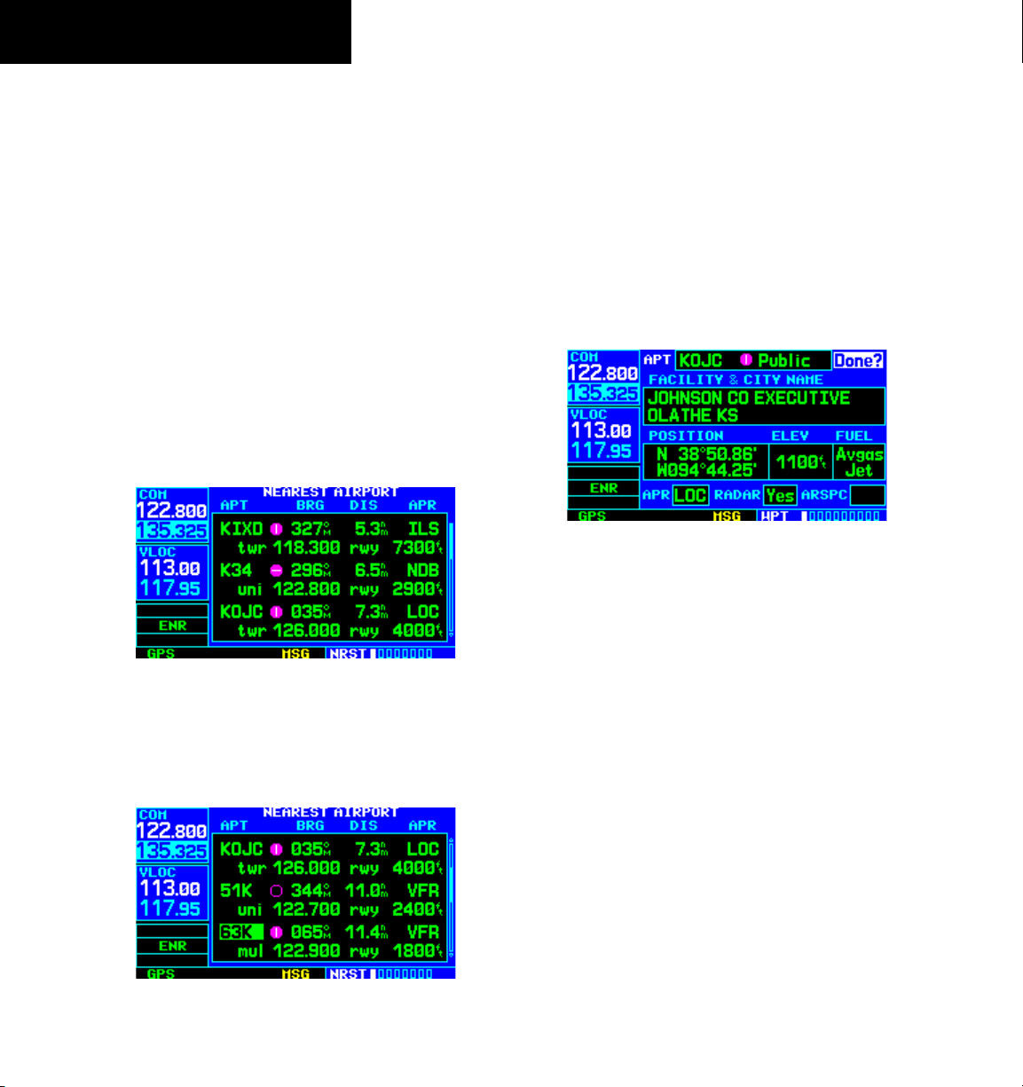
To display a list of nearby airports:
1) Turn the large
right knob to select the NRST
Page Group and (if needed) the small right
knob to select the Nearest Airport Page (Figure
1-24).
Figure 1-24 Nearest Airport Page
2) To scroll through the list, press the small right
knob, then turn the large right knob (Figure
1-25)
To view additional information for a nearby
airport:
1) Press the small right knob to activate the
cursor.
2) Turn the large
right knob to select the desired
airport from the list.
3) Press the
ENT Key to display waypoint (WPT)
information pages for the selected airport
(Figure 1-26).
Figure 1-26 Airport Location Page
4) To display runway and frequency information,
press the small right knob to remove the
cursor and turn the small right knob to display
the desired information page.
The Nearest Airport Page may be used in conjunction
with the Direct-to Key to quickly set a course to a nearby
facility in an in-flight emergency. Selecting a nearby
airport as a direct-to destination overrides the flight plan
or cancels a previously selected direct-to destination. (The
pilot still has the option of returning to the flight plan
by cancelling the direct-to; see Section 4.1, Cancelling
Direct-to Navigation.)
1-16
Figure 1-25 Scrolling the Nearest Airport List
GNS 430 Pilot’s Guide and Reference
Page 25
SECTION 1
INTRODUCTION
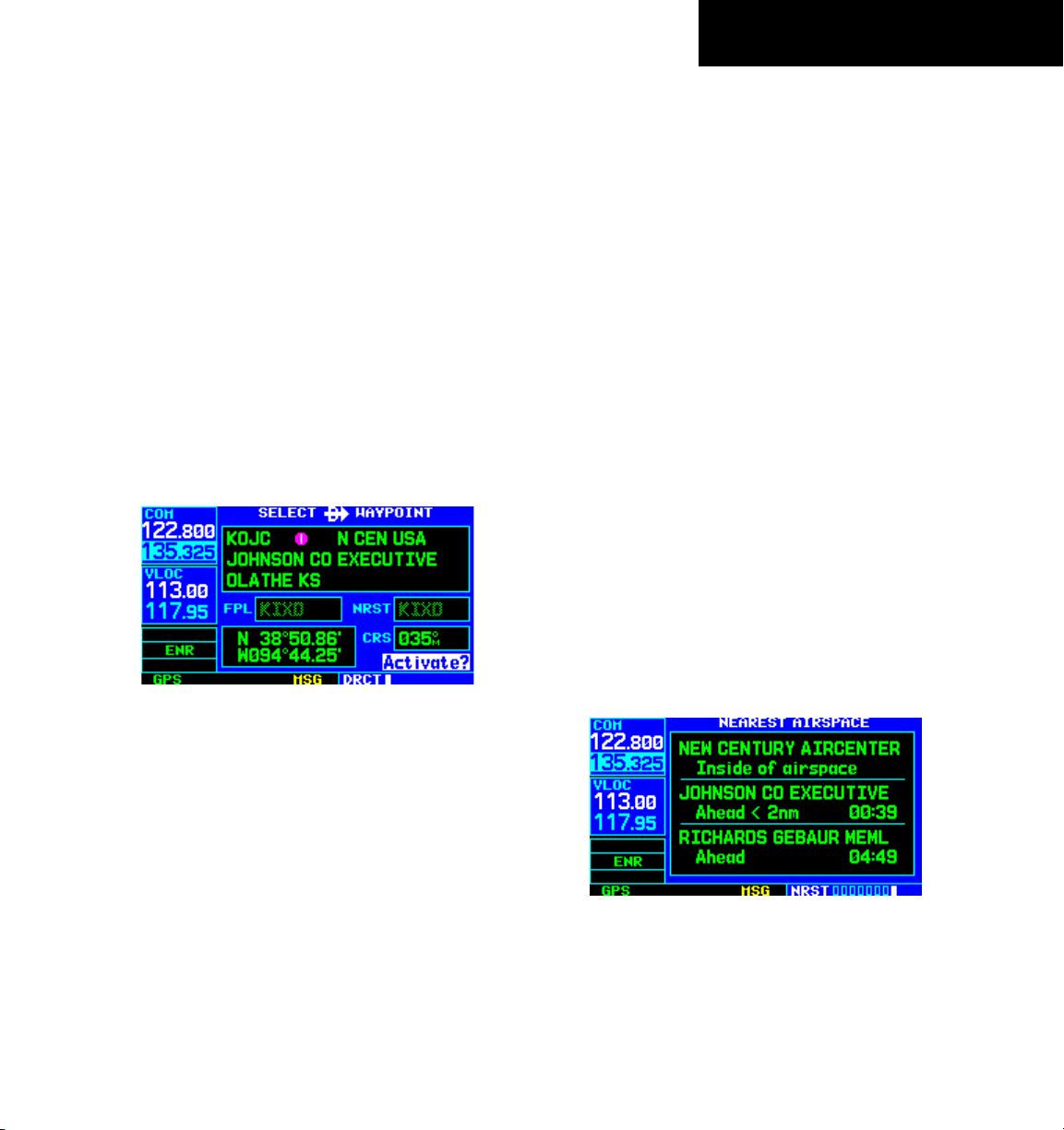
To select a nearby airport as a direct-to
destination from the Nearest Airport Page:
1) From the Nearest Airport Page, press the small
right knob to activate the cursor.
2) Turn the large
right knob to select the desired
airport from the list.
3) Press the Direct-to Key, the ENT Key, and
the ENT Key (again) to navigate to the nearby
airport.
To select a nearby airport as a direct-to
destination from the Airport Information
Page:
1) Press the Direct-to Key, then press the
ENT
Key (Figure 1-27).
Nearest (NRST) Airspace Page
The last page in the NRST group, the Nearest Airspace
Page (Figure 1-28), provides information for up to nine
controlled or special-use airspaces near or in the flight
path. Airspace information appears on this page based
upon the same criteria used for airspace alert messages.
Nearby airspace information and airspace alert messages
are provided according to the following conditions:
• If the projected course will take the aircraft inside
an airspace within the next ten minutes, the
message ‘Airspace ahead -- less than 10 minutes’
appears.
• If the aircraft is within two nautical miles of an
airspace and the current course will take it inside
of the airspace, the message ‘Airspace near and
ahead’ appears.
• If the aircraft is within two nautical miles of an
airspace and the current course will not take it
inside of the airspace, the message ‘Near airspace
less than 2nm’ appears.
Figure 1-27 ‘Activate?’ Highlighted
2) Press the ENT Key again to navigate to the
nearby airport.
GNS 430 Pilot’s Guide and Reference
• If the aircraft has entered an airspace, the message
‘Inside airspace’ appears.
Figure 1-28 Nearest Airspace Page
1-17
Page 26
SECTION 1
INTRODUCTION
By default, airspace alert messages are turned off. When
turned on, the message (MSG) annunciator located directly
above the MSG Key flashes to alert the pilot to the airspace
message. See Section 10.4, Setup 1 Page: Airspace Alarms
for information on enabling airspace alert messages.
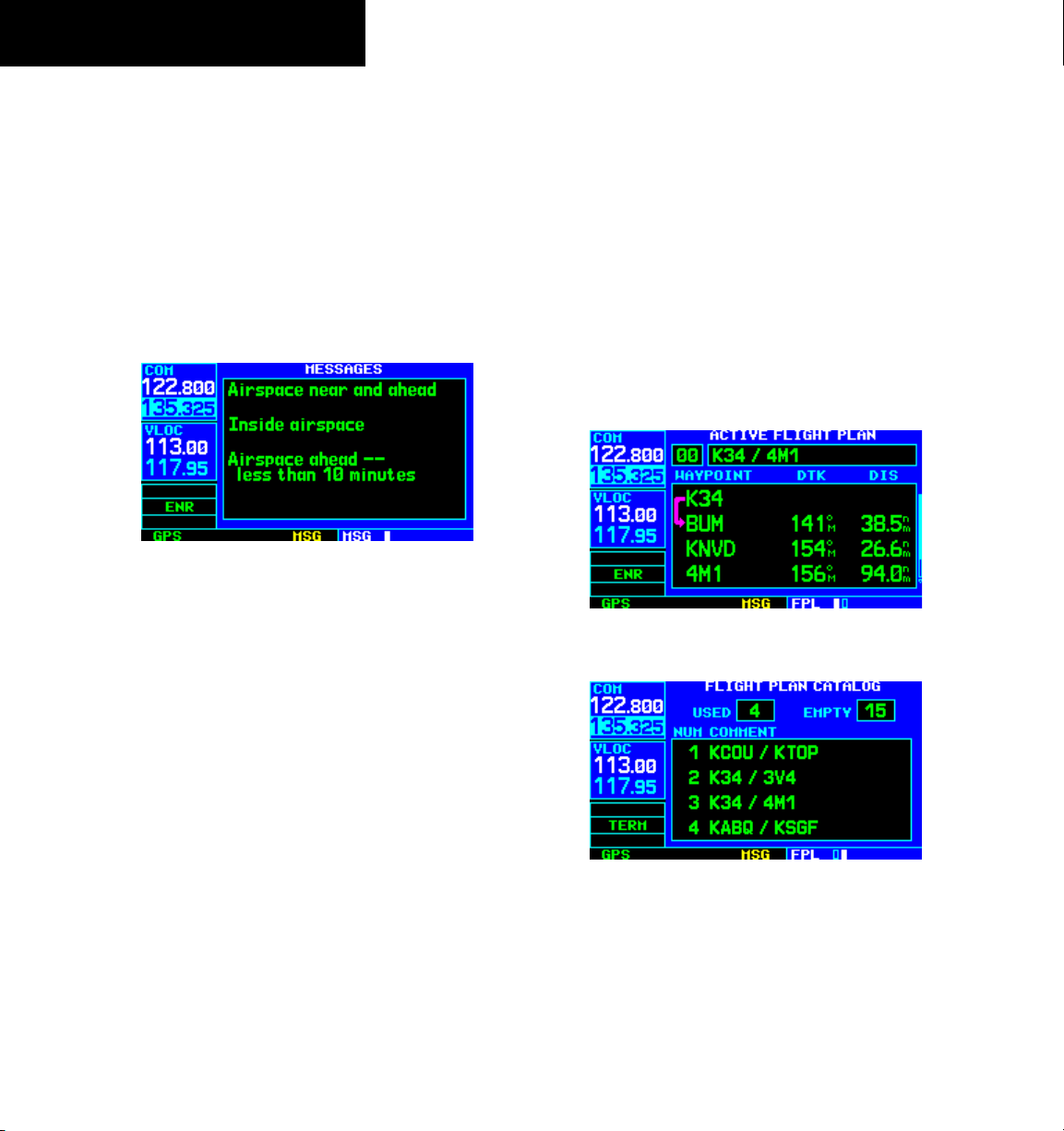
To view an airspace alert message:
1) Press the MSG Key. The Messages Page
appears with the alert message (Figure
1-29).
Figure 1-29 Messages Page
2) Press the MSG Key again to return to the
previous display.
Flight Plans (FPL)
The GNS 430 lets the pilot create up to 20 flight plans
with up to 31 waypoints in each flight plan. Flight plans
are created, edited, and activated using the FPL Key. The
FPL Page Group includes two pages: the Active Flight Plan
Page and the Flight Plan Catalog Page (Figures 1-30 and
1-31). The Active Flight Plan Page provides information
and editing features for the flight plan currently in use
(referred to as ‘flight plan 00’). The Flight Plan Catalog
Page serves as the main page for creating new flight plans,
as well as editing or activating previously created flight
plans.
Figure 1-30 Active Flight Plan Page
1-18
Note that the airspace alerts are based upon threedimensional data (latitude, longitude, and altitude) to
avoid nuisance alerts. The alert boundaries for controlled
airspace are also sectorized to provide complete information
on any nearby airspace. Additional information about a
nearby airspace—such as controlling agency, frequency, and
floor/ceiling limits—is available from the Nearest Airspace
Page (Section 8.9).
To view additional airspace information:
1) Press the small right knob to activate the
cursor.
2) Turn the large
right knob to select the desired
airspace from the list.
3) Press the ENT Key to view the airspace
information.
GNS 430 Pilot’s Guide and Reference
Figure 1-31 Flight Plan Catalog Page
Page 27
SECTION 1
INTRODUCTION
Since using flight plans is arguably one of the more
complex features of the GNS 430, it will be discussed only
briefly here, with focus on creating a new flight plan and
activating it to use for navigation. Answers to additional
questions about flight plans not found in this brief
introduction can be found in Section 5, Flight Plans.
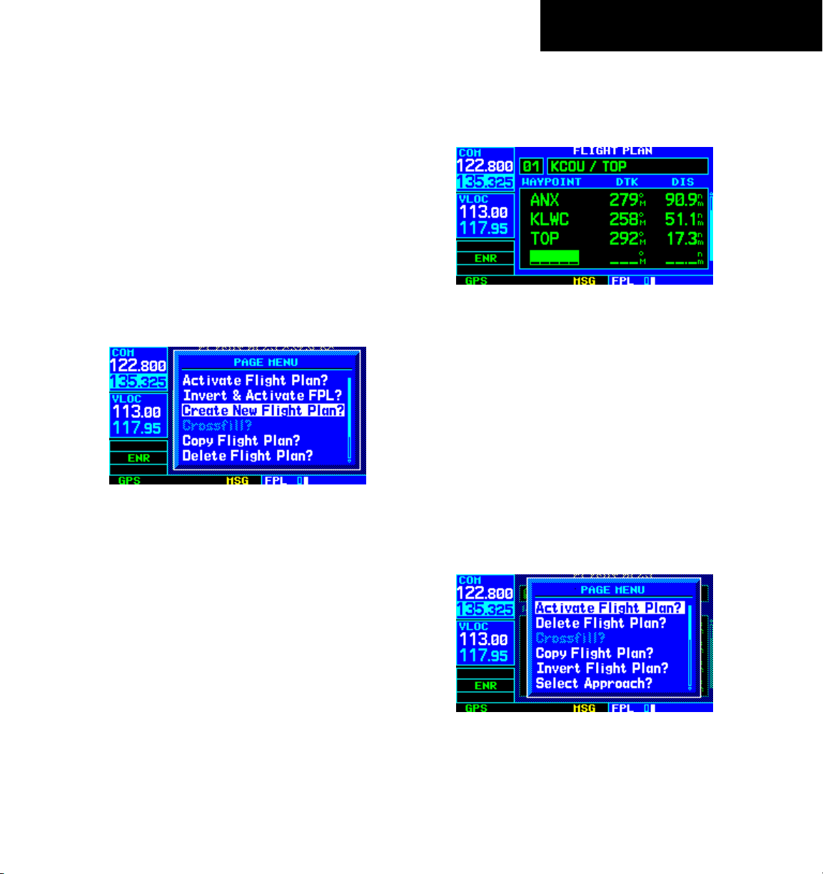
To create a new flight plan:
1) Press the
2) Turn the small
FPL Key.
right knob to select the Flight
Plan Catalog Page.
3) Press the
MENU Key to display the Flight Plan
Catalog Page Menu (Figure 1-32).
Figure 1-32 Flight Plan Catalog Page Menu
4) Turn the large right knob to select ‘Create New
Flight Plan?’ and press the ENT Key.
7) Repeat steps 5 and 6, above, until all waypoints
for the flight plan have been entered (Figure
1-33).
Figure 1-33 Enter Flight Plan Waypoints
Once the flight plan is created, it may be activated from
the Flight Plan Catalog Page Menu. Activating the flight
plan places it into ‘flight plan 00’ (a copy of it still resides
in the original catalog location) and replaces any flight
plan which currently exists in ‘flight plan 00’.
To activate the new flight plan:
1) Press the
MENU Key to display the Flight Plan
Catalog Page Menu.
2) Turn the small
right knob to select ‘Activate
Flight Plan?’ (Figure 1-34) and press the ENT
Key
5) The cursor appears on the first waypoint identifier
field (located directly below ‘WAYPOINT’). Use
the large and small
right knobs to enter the
identifier of the first waypoint in the flight plan.
(The small knob is used to select the desired
letter or number and the large knob is used to
move to the next character space.)
6) Press the ENT Key once the identifier has been
selected. The cursor moves to the next blank
waypoint identifier field.
GNS 430 Pilot’s Guide and Reference
Figure 1-34 Flight Plan Catalog Page Menu
1-19
Page 28

SECTION 1
INTRODUCTION
Blank Page
1-20
GNS 430 Pilot’s Guide and Reference
Page 29

SECTION 2
COM
SECTION 2: COM
2.1 COMMUNICATING USING THE GNS 430
The GNS 430 features a digitally-tuned VHF COM radio
that provides a seamless transition from communication
to navigation, bringing the two most important functions
in flying together in one panel-mounted unit. The GNS
430’s COM radio operates in the aviation voice band, from
118.000 to 136.975 MHz, in 25 kHz steps (default). For
European operations, a COM radio configuration to allow
for 8.33 kHz steps is also provided (Section 10.5, Setup 2
Page: COM Configuration).
Volume
COM radio volume is adjusted using the COM Power/
Volume Knob. Turn the COM Power/Volume Knob
clockwise to increase volume, or counterclockwise to
decrease volume.
Squelch
The COM radio features an automatic squelch,
providing maximum sensitivity to weaker signals while
rejecting many localized noise sources. The pilot may
wish to override this automatic squelch function when
listening to a distant station or when setting the desired
volume level. The COM Power/Volume Knob allows
the pilot to disable the automatic squelch and keep
the COM audio open continuously. To override the
automatic squelch, press the COM Power/Volume Knob
momentarily. Press the COM Power/Volume Knob again
to return to automatic squelch operation.
COM Window and Tuning
Communication frequencies are selected with the
tuning cursor in the standby COM frequency field (Figure
2-1), using the small and large left knobs to dial in the
desired frequency. The standby frequency always appears
below the active frequency. The active frequency is
the frequency currently in use for transmit and receive
operations.
‘RX’ Receive Indication
Standby COM
Frequency Field
Figure 2-1 ‘RX’ Receive Indication
A frequency may also be quickly selected from the
database by simply highlighting the desired frequency on
any of the main pages and pressing the ENT Key. This
process is referred to as auto-tuning. Once a frequency is
selected in the standby field, it may be transferred to the
active frequency by pressing the COM Flip-flop Key.
GNS 430 Pilot’s Guide and Reference
2-1
Page 30
SECTION 2
COM
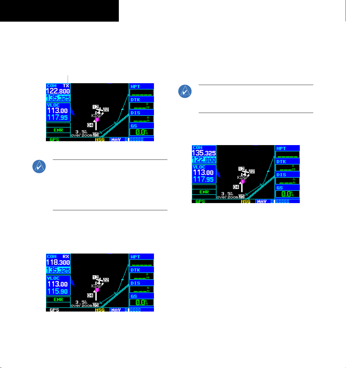
While receiving a station, an ‘RX’ indication (Figure
2-1) appears in the upper right corner of the COM Window
to the immediate right of ‘COM’. A ‘TX’ indication appears
at this location when transmitting (Figure 2-2).
‘TX’ Transmit Indication
Figure 2-2 ‘TX’ Transmit Indication
NOTE: The tuning cursor normally appears in the
COM Window, unless placed in the VLOC Window
by pressing the small left knob. When the tuning
cursor is in the VLOC Window, it automatically
returns to the COM Window after 30 seconds of
inactivity.
To select a COM frequency:
1) If the tuning cursor is not currently in the
COM
Window, press the small left knob momentarily
(Figure 2-3).
2) Turn the large left knob to select the desired
megahertz (MHz) value. For example, the ‘135’
portion of the frequency ‘135.325’.
3) Turn the small
left knob to select the desired
kilohertz (kHz) value. For example, the ‘.325’
portion of the frequency ‘135.325’.
NOTE: The active frequency in either window
cannot be accessed directly, only the standby
frequency is highlighted by the tuning cursor.
4) To make the standby frequency the active
frequency, press the COM Flip-flop Key
(Figure 2-4).
Figure 2-4 Active Frequency of 135.325
The tuning cursor is normally in the COM Window.
To select a VOR/Localizer/ILS frequency, press the small
left knob momentarily to place the cursor in the VLOC
Window. Additional instructions for VOR/localizer/ILS
operations are available in Sections 6 and 9.
2-2
Figure 2-3 Standby Frequency of 135.325
GNS 430 Pilot’s Guide and Reference
Page 31

SECTION 2
COM
Auto-Tuning
The GNS 430’s auto-tune feature allows the pilot to
quickly select any database frequency in the GPS Window
as the standby frequency. Any COM frequency displayed
in the GPS Window can be transferred to the standby
COM frequency field, with a minimum of keystrokes
required. The following are some examples of selecting
COM frequencies from some of the main GPS pages.
To select a COM frequency for a nearby
airport:
1) Turn the large
Page Group.
2) Turn the small right knob to display the
Nearest Airport Page (Figure 2-5)
right knob to select the NRST
To display the entire list of frequencies for
a nearby airport and select from that list:
1) Start with the desired airport highlighted on
the Nearest Airport Page (as described in the
preceding step 3), then press the ENT Key.
2) Press the small right knob momentarily to
remove the cursor and turn the small
right
knob to display the frequency list (Figure
2-6).
Figure 2-6 Airport Frequencies Page
3) Press the small right knob momentarily to
reactivate the cursor and turn the large right
knob to highlight the desired frequency.
Figure 2-5 Nearest Airport Page
3) Press the small right knob momentarily to
place the cursor on the airport identifier field
of the first airport in the list. To select another
airport, turn the large right knob to highlight
the desired airport.
4) The Nearest Airport Page displays the common
traffic advisory frequency (CTAF) for each listed
airport. To select this frequency, turn the large
right knob to highlight the desired airport’s
CTAF frequency and press the ENT Key to place
the frequency in the standby field of the COM
Window.
GNS 430 Pilot’s Guide and Reference
4) Press the ENT Key to place the highlighted
frequency in the standby COM field.
2-3
Page 32

SECTION 2
COM
To select a COM frequency for a nearby
flight service station (FSS) or center
(ARTCC):
1) Turn the large
right knob to select the NRST
Page Group.
2) Turn the small right knob to select the Nearest
Center or Nearest Flight Service Page (Figure
2-7).
Figure 2-7 Nearest ARTCC Page
3) Press the small right knob momentarily to
place the cursor on the page.
4) Turn the large right knob to highlight the
FSS/ARTCC frequency.
To select a COM frequency for any airport
in the flight plan:
1) Select the NAV/COM Page from the NAV Page
Group. (Section 3.1, or press and hold the CLR
Key, then turn the small right knob until the
NAV/COM Page appears.)
2) Press the small
right knob to place the cursor
on the airport identifier field. To the left of this
field appears Departure, Enroute, or Arrival,
depending on the placement of the displayed
airport within the flight plan.
3) Turn the small right knob to display a window
(Figure 2-8) listing the airports in the flight
plan. Continue turning the small
right knob
to select the desired airport.
2-4
5) Press the
ENT Key to place the frequency in
the standby field of the COM Window.
Figure 2-8 NAV/COM Page ‘Airport’ Window
4) Press the ENT Key to return to the NAV/COM
Page with the frequencies for the selected
airport.
5) Turn the large right knob to highlight the
desired frequency.
6) Press the ENT Key to place the highlighted
frequency in the standby COM Window field.
GNS 430 Pilot’s Guide and Reference
Page 33

SECTION 2
COM
To select a COM frequency for any airport
in the database:
1) Turn the large
right knob to select the NRST
Page Group.
2) Turn the small
right knob to select the Airport
Frequencies Page (Figure 2-9).
Figure 2-9 Airport Frequencies Page
3) Press the small right knob to place the cursor
on the airport identifier field.
4) Use the small and large
right knobs to enter
the identifier of the desired airport. Press the
ENT Key when finished.
Emergency Channel
The GNS 430’s emergency channel select provides
a quick method of selecting 121.500 MHz as the
active frequency in the event of an in-flight emergency.
Emergency channel select is available anytime the unit
is on, regardless of GPS or cursor status, or loss of the
display.
To quickly tune and activate 121.500:
Press and hold the COM Flip-flop Key for
approximately two seconds (Figure 2-10).
Figure 2-10 Emergency Channel Active
5) Turn the large right knob to highlight the
desired frequency.
6) Press the ENT Key to place the highlighted
frequency in the standby COM Window field.
GNS 430 Pilot’s Guide and Reference
2-5
Page 34

SECTION 2
COM
Stuck Microphone
As mentioned previously in this section, when the GNS
430 is transmitting, a ‘TX’ indication appears in the COM
Window. If the microphone key is stuck or accidentally
left in the on position; or the microphone continues to
transmit after the key is released, the COM transmitter
automatically times out (ceases transmitting) after 35
seconds of continuous broadcasting. A ‘COM push-totalk key stuck’ message (Figure 2-11) is displayed as long
as the condition continues.
2-6
Figure 2-11 Message Page
GNS 430 Pilot’s Guide and Reference
Page 35

SECTION 3
Default NAV
Map
TERRAIN
NAVCOM
Position
Satellite Status
VNAV
(if configured)
NAV PAGES
SECTION 3: NAV PAGES
3.1 MAIN PAGE GROUPS
The GNS 430’s main pages are divided into four
separate page groups: NAV, WPT, AUX, and NRST
(Table 3-1). Each page group is comprised of multiple
pages. The page groups are selected using the large right
knob. The individual pages are selected using the small
right knob.
Page Groups
NAV Group WPT Group AUX Group NRST Group
7 NAV Pages
The bottom right corner of the screen (Figure 3-1)
indicates which page group is currently being displayed
(e.g., NAV, WPT, AUX, or NRST), the number of screens
available within that group (indicated by the square icons),
and the placement of the current screen within that group
(indicated by a highlighted square icon).
see Section 7 see Section 10 see Section 8
Table 3-1 Page Groups
To select the desired page group (from any
page):
Press and hold the CLR Key to select the
Default NAV Page. Turn the large
right knob
to select the desired page group (Table 3-1 and
Figure 3-1).
To select the desired page within the
group:
Turn the small right knob to select the desired
page (Figures 3-1 and 3-2).
3.2 NAV PAGE GROUP
The NAV Page Group includes seven pages (Figure
3-2). While viewing any NAV page, turn the small right
knob to select a different NAV page. The pilot may find
this selection process convenient to cycle between the
Default NAV Page and the Map Page, which are two of the
most frequently used pages. Other pages are provided for
terrain information (if configured for TERRAIN), to list
frequencies for the flight plan, show the current position,
display current satellite reception, and make vertical
navigation settings.
Current Page Group
Figure 3-1 Current Page and Page Group
Number of Pages in
Current Page Group
GNS 430 Pilot’s Guide and Reference
Position of
Current Page
within Current
Page Group
Figure 3-2 NAV Pages
3-1
Page 36

SECTION 3
NAV PAGES
3.3 DEFAULT NAV PAGE
The first NAV page is the Default NAV Page (Figure
3-3). This page may be quickly selected from any page by
pressing and holding the CLR Key.
Active Leg of Flight Plan
Course Deviation Indicator (CDI)
TO/FROM Flag
Position of
Current Page
within Current
Page Group
User-selectable
Data Fields
Current Page Group
Figure 3-3 Default NAV Page
The Default NAV Page displays a graphic course
deviation indicator (CDI) across the top of the page. Unlike
the angular limits used on a mechanical CDI coupled to
a VOR or ILS receiver, full scale limits for this CDI are
defined by a GPS-derived distance (0.3, 1.0 or 5.0 nm), as
indicated at both ends of the CDI. By default, the CDI scale
automatically adjusts to the desired limits based upon the
current phase of flight: enroute, terminal area or approach.
The pilot may also manually select the desired scale setting
as outlined in Section 10.4. The graphic CDI shows the
current position at the center of the indicator, relative to
the desired course (the moving course deviation needle).
As with a traditional mechanical CDI, when off course
simply steer toward the needle. The TO/FROM arrow in the
center of the scale indicates whether the aircraft is heading
TO (up arrow) or FROM the waypoint (down arrow).
Number of Pages in
Current Page Group
NOTE: The GNS 430 always navigates TO
a waypoint unless the OBS switch is set
(preventing automatic waypoint sequencing),
or if the aircraft has passed the last waypoint
in the flight plan.
Directly below the CDI appears the active leg of the
flight plan, or the direct-to destination when using the
Direct-to Key. This automatically sequences to the next
leg of the flight plan as each interim waypoint is reached.
If no flight plan or direct-to destination has been selected,
the destination field remains blank.
The following symbols are used on the Default NAV
Page (directly below the CDI), to depict the ‘active leg’ of
a flight plan or direct to:
Direct-to a Waypoint
Course to a Waypoint, or Desired
Course between Two Waypoints
Procedure Turn
Procedure Turn
Vectors-to-Final
DME Arc to the Left
DME Arc to the Right
Left-hand Holding Pattern
Right-hand Holding Pattern
3-2
GNS 430 Pilot’s Guide and Reference
Page 37

SECTION 3
NAV PAGES
Selecting Desired On-Screen Data
At the bottom of the Default NAV Page there are six
user-definable fields which display the data needed as
the flight progresses (Figure 3-3). By default these fields
display: distance to destination (DIS), desired track
(DTK), bearing to destination (BRG), ground speed (GS),
ground track (TRK), and estimated time enroute (ETE).
However, each of these fields can be customized to display
a different data item. Available data items include:
• Bearing to destination (BRG)
• Course to steer (CTS)
• Cross track error (XTK)
• Desired
• Distance to destination (
• Enroute safe altitude (ESA)
• Estimated time of arrival (ETA)
• Estimate time enroute (
• Fuel flow (FLOW) (when configured)
track (DTK)
DIS)
ETE)
To select a different data item for any data
field:
1) Starting with the Default NAV Page, press the
MENU Key to display the Default NAV Page
Menu (Figure 3-4).
Figure 3-4 Default NAV Page Menu
2) The ‘Change Fields?’ option is already
highlighted, so press the ENT Key to select
this option.
3) Use the large
right knob to highlight the data
field to be changed (Figure 3-5).
• Ground speed (GS)
• Ground
• Minimum safe altitude (
track (TRK)
MSA)
• Track angle error (TKE)
• Vertical speed required (
VSR)
If no flight plan or direct-to destination has been
selected, only speed, track, altitude, and minimum safe
altitude data may be displayed. All other data types appear
as blank lines on the Default NAV Page until a destination
is selected.
GNS 430 Pilot’s Guide and Reference
Figure 3-5 ‘DIS’ Field Highlighted
3-3
Page 38

SECTION 3
NAV PAGES
4) Turn the small right knob to display the list of
available data items (Figure 3-6). Continue
turning the small right knob to select the
desired data item from the list.
Figure 3-6 Select Field Type Window
5) Press the ENT Key to select the desired data
item and return to the Default NAV Page.
6) Press the small right knob momentarily to
remove the cursor from the page.
Restoring Factory Settings
All data fields settings can be quickly returned to
original factory settings.
To restore all six data fields to factory
default settings:
1) From the Default NAV Page, press the
Key to display the Default NAV Page Menu.
2) Turn the large right knob to highlight the
‘Restore Defaults?’ option (Figure 3-7) and
press the ENT Key.
Figure 3-7 Default NAV Page Menu
MENU
3-4
Dual Unit Considerations
A ‘Crossfill?’ option is also provided for the Default
NAV Page. This option transfers a direct-to destination
or flight plan to a second Garmin 400 Series unit. See
Section 10.2, Flight Planning: Crossfill for additional
details on using the crossfill option.
GNS 430 Pilot’s Guide and Reference
Page 39

SECTION 3
NAV PAGES
3.4 MAP PAGE
The second NAV page is the Map Page (Figure 3-8),
which displays the present position using an airplane
symbol, along with nearby airports, NAVAIDS, userdefined waypoints, airspace boundaries, lakes, rivers,
highways, and cities.
Present Position
Map Display
Map Range
Current Page Group
Figure 3-8 Map Page
Data Fields
Position of
Current Page
within Current
Page Group
Number of Pages in
Current Page Group
The following symbols are used to depict the various
airports and NAVAIDS on the
Map Page:
Airport with hard surface runway(s);
(primary runway shown)
Airport with soft surface runway(s) only
Private Airfield
VOR
VOR/DME
DME
Localizer
Intersection
VORTAC
TACAN
NOTE: If the GNS 430 is unable to determine
a GPS position, the present position (airplane)
symbol does not appear on the Map Page.
Different symbols are used to distinguish between
waypoint types. The identifiers for any on-screen
waypoints can also be displayed. (The identifiers are
enabled by default.) Special-use and controlled airspace
boundaries appear on the map, showing the individual
sectors for Class B, Class C, and Class D airspaces.
GNS 430 Pilot’s Guide and Reference
NDB
Locator Outer Marker
The Map Display can be set to 23 different range
settings from 500 feet to 2000 nautical miles (statute and
metric units are also available). The range is indicated
in the lower left-hand corner of the Map Display (Figure
3-8), and represents the top-to-bottom distance covered
by the Map Display.
3-5
Page 40

SECTION 3
NAV PAGES
To select a map range:
1) Press the up arrow of the
RNG Key to zoom
out to a larger map area.
2) Press the down arrow of the RNG Key to zoom
in to a smaller map area and more detail.
An autozoom feature is available which automatically
adjusts from an enroute range of 2000 nm through
each lower range, stopping at a range of 1.0 nm when
approaching the destination waypoint. The autozoom
feature is turned on/off from the Map Setup Page (described
in Section 3.4).
The Map Page also displays a background map (or
‘basemap’) showing lakes, rivers, coastlines, highways,
railways, and towns. When a map range is selected below
the lower limit at which the map detail was originally
created, an ‘overzoom’ indication appears on the Map
Display, below the range reading (Figure 3-9). The
basemap has limited accuracy, and should not be used
for navigation, but only for non-navigational situational
awareness. Any basemap indication should be compared
against other navigational sources for accuracy. Continuing
to zoom in to lower range settings will cause ‘overzoom’ to
be replaced with ‘no map’ and the geographic detail will
be removed from the Map Display (airport and NAVAID
remain).
The ‘Setup Map?’ option (described in Section 3.4)
allows the pilot to define the maximum range at which
each map feature appears. This provides the pilot with
complete control to minimize screen clutter. The pilot
can also quickly remove items from the map using the
CLR Key.
To quickly declutter the Map Display:
Press the
CLR Key momentarily (as often as
needed) to select the desired amount of map
detail.
The CLR Key allows the pilot to quickly declutter the
Map Display, providing four levels of map detail. Note
the ‘-2’ (‘-1’ and ‘-’ are also provided) suffix designation in
Figure 3-10, indicating each successive declutter level.
Map Detail Level
Figure 3-10 Detail Level on Map Page
3-6
Figure 3-9 Overzoom on Map Page
GNS 430 Pilot’s Guide and Reference
The right-hand side of the Map Page includes four
user-selectable data fields (Figure 3-8). By default, the
displayed data is: destination waypoint name (WPT),
desired track (DTK), distance to destination waypoint
(DIS), and ground speed (GS). Any of these data fields
may be changed to display a different data type, as outlined
in Section 3.4. The four data fields can also be removed
from the map to show a larger map image, as described in
Section 3.4.
Page 41

SECTION 3
NAV PAGES
Map Panning
Another Map Page function is panning, which allows the
map to move beyond its current limits without adjusting
the map range. When the panning function is selected (by
pressing the small right knob), a target pointer flashes on
the Map Display (Figure 3-11). A window also appears at
the top of the Map Display showing the latitude/longitude
position of the pointer, plus the bearing and distance to
the pointer from the present position.
Pointer Position
Window
Figure 3-11 Panning on Map Page
Target Pointer
When the target pointer is placed on an object, the
name of that object is highlighted (even if the name wasn’t
originally displayed on the map). This feature applies to
airports, NAVAIDS, user-created waypoints, roads, lakes,
rivers, almost everything displayed on the map except
route lines.
When an airport, NAVAID, or user waypoint is selected
on the Map Display, information about the waypoint can
be reviewed or the waypoint can be designated as the
direct-to destination.
To review information for an on-screen
airport, NAVAID or user waypoint:
1) Use the panning function (as described in
the preceding procedure) to place the
target
pointer on a waypoint (Figure 3-11).
2) Press the ENT Key to display the Waypoint
Information Page(s) for the selected waypoint
(Figure 3-12).
To select the panning function and pan the
Map Display:
1) Press the small right knob to activate the
panning target pointer.
2) Turn the small
right knob to move up (turn
clockwise) or down (counterclockwise).
3) Turn the large
right knob to move right (turn
clockwise) or left (counterclockwise).
4) To cancel the panning function and return to
the present position, press the small right
knob.
GNS 430 Pilot’s Guide and Reference
Figure 3-12 Information for On-Screen Waypoint
3) Press the CLR Key to exit the information
page(s).
3-7
Page 42

SECTION 3
NAV PAGES
Map Direct-to
To designate an on-screen airport,
NAVAID, or user waypoint as the direct-to
destination:
1) Use the panning function (‘Map Panning’ in
this section) to place the
waypoint.
2) Press the Direct-to Key to display the select
Direct-to Waypoint Page, with the selected
waypoint already listed (Figure 3-13).
Figure 3-13 +MAP Waypoint
target pointer on a
Airspace Information on the Map
When a special-use or controlled airspace boundary
appears on the Map Display, the pilot can quickly retrieve
information (such as floor/ceiling limits and controlling
agency) directly from the map.
To view airspace information for an onscreen special-use or controlled airspace:
1) Use the panning function (‘Map Panning’ in this
section) to place the target pointer on an open
area within the boundaries of an airspace. If
the area is congested and it is difficult to select
an open area, it may be necessary to zoom in
or press the
easier (Figure 3-14).
CLR Key to make the selection
3-8
3) Press the ENT Key twice to confirm the selection
and begin navigating to the waypoint.
Figure 3-14 Select Airspace with Target Pointer
The direct-to function can be used anywhere on the
map. If nothing currently exists at the target pointer
location, a new waypoint called ‘+MAP’ (Figure 3-13) is
created at the target pointer location before the direct-to
is initiated.
GNS 430 Pilot’s Guide and Reference
Page 43

SECTION 3
NAV PAGES
2) Press the ENT Key to display an options menu
(Figure 3-15).
Figure 3-15 Map Panning Options Window
3) ‘R ev ie w Airsp ac e? ’ should already be
highlighted, if not select it with the small
right knob. Press the ENT Key to display the
Airspace Information Page for the selected
airspace.
4) To display the COM frequency(ies) for the
controlling agency, turn the large right knob to
highlight ‘Frequencies?’ and press the ENT Key.
Press the
CLR Key to return to the Airspace
Information Page.
Map Setup
Many of the GNS 430’s functions are menu driven.
Each of the main pages has an options menu, allowing
customization of the corresponding page to the pilot’s
preferences and/or selection of special features which
specifically relate to that page. A Map Page Menu (Figure
3-16) provides additional settings to customize the Map
Page and additional features related specifically to the
Map Page.
To display the Map Page Menu:
Press the MENU Key with the Map Page
displayed (Figure 3-16).
Figure 3-16 Map Page Menu
5) Press the CLR Key to exit the Airspace
Information Page.
GNS 430 Pilot’s Guide and Reference
The following options are available: ‘Setup Map?’,
‘Measure Dist?’, ‘Data Fields Off?’, ‘Change Fields?’, and
‘Restore Defaults?’.
‘Setup Map?’ allows configuration of the Map Display
to individual preferences, including map orientation,
land data enable/disable, Jeppesen data enable/disable,
automatic zoom, airspace boundaries, and text size.
3-9
Page 44
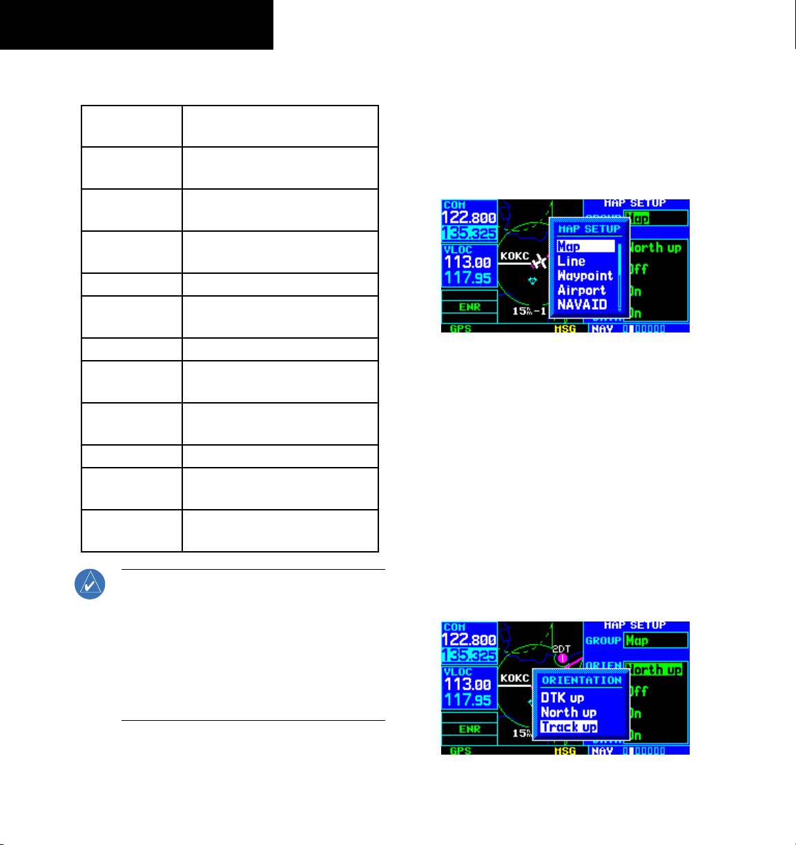
SECTION 3
NAV PAGES
The following settings are available for each group:
Map Orientation, AutoZoom, Land Data,
Aviation Data
Weather
Lightning Mode/Symbol
(when applicable)
Traffic Traffic Mode/Symbol/Label
(when applicable)
Airport Large/Medium/Small Airports and
Text
NAVAID VORs, NDBs, Intersections, and Text
Waypoint User Waypoints, Waypoint Text,
Flight Plan Wpts
Line Active Flight Plan, Lat/Long
Control Controlled Airspace: Class B, C, D
(tower zone)
Airspace Special-Use Airspace: Restricted,
MOA, Other
City Large/Medium/Small Cities and Text
Road Freeway, National Highway, Local
Hwy, Local Road
Other States/Prov, Rivers/Lakes, Railroads,
Wind Vector
NOTE: Large, medium, and small classifications
are used on the GNS 430 for airports and cities.
Large airports are those with a runway longer
than 8100 feet. Medium airports include those
with a runway longer than 5000 feet or with
a control tower. Large cities are those with
approximate populations greater than 200,000
and medium cities with greater than 50,000.
To change map orientation:
1) From the Map Page Menu, turn the large right
knob to highlight ‘Setup Map?’ (Figure 3-16)
and press the ENT Key.
2) Turn the small right knob to select ‘Map’
(Figure 3-17) and press the ENT Key.
Figure 3-17 Map Setup Window
3) Turn the large right knob to highlight the
‘Orientation’ field.
4) Turn the small right knob to select the desired
option.
a) Select ‘DTK up’ to fix the top of the Map Display
to the desired course.
b) Select ‘North up’ to fix the top of the Map
Display to a north heading.
c) Select ‘Track up’ (Figure 3-18) to adjust the
top of the Map Display to the current track
heading.
3-10
Figure 3-18 Orientation Window
GNS 430 Pilot’s Guide and Reference
Page 45

SECTION 3
NAV PAGES
d) Press the ENT Key to accept the selected option
(Figure 3-19).
Figure 3-19 Map Setup Page
To enable/disable automatic zoom:
1) From the Map Page Menu, turn the large right
knob to highlight ‘Setup Map?’ and press the
ENT Key.
2) Turn the small
right knob to select ‘Map’ and
press the ENT Key.
3) Turn the large right knob to highlight the ‘Auto
Zoom’ field.
4) Turn the small right knob to select ‘On’ or
‘Off’.
5) Press the ENT Key to accept the selected option.
The automatic zoom feature automatically
adjusts the map range from 2000 nm through
each lower range, stopping at 1.0 nm when
approaching the destination waypoint.
3) Turn the large right knob to highlight the
appropriate field.
4) Turn the small right knob to select ‘On’ or
‘Off’.
5) Press the ENT Key to accept the selected
option.
For airports, NAVAIDs, active flight plan
waypoints, user-created waypoints, state/
provincial boundaries, rivers/lakes, and
cities:
1) From the Map Page Menu, turn the large right
knob to highlight ‘Setup Map?’ and press the
ENT Key.
2) Turn the small right knob to select the
appropriate ‘Group’ name (per the chart on
the preceding page) and press the ENT Key.
3) Turn the large right knob to highlight the zoom
field for the desired feature.
4) Turn the small right knob to select the
maximum range at which the feature should
appear on screen (or select ‘Off’ to never
display the selected feature).
5) Press the ENT Key to accept the selected
option.
6) Turn the large
right knob to highlight the text
field for the desired feature.
To enable/disable the wind vector, all
background land data, or all Jeppesen
aviation data:
1) From the Map Page Menu, turn the large right
knob to highlight ‘Setup Map?’ and press the
ENT Key.
2) Turn the small
right knob to select ‘Map’ and
press the ENT Key.
GNS 430 Pilot’s Guide and Reference
7) Turn the small right knob to select the desired
text size, or select ‘None’ to disable text
descriptions.
8) Press the ENT Key to accept the selected
option.
3-11
Page 46

SECTION 3
NAV PAGES
For airspace boundaries, highways, roads,
railroad lines, track log data, active flight
plan course lines, and lat/long grid lines:
1) From the Map Page Menu, turn the large right
knob to highlight ‘Setup Map?’ and press the
ENT Key.
2) Turn the small right knob to select the
appropriate ‘Group’ name (per the chart on
the preceding page) and press the ENT Key.
3) Turn the large right knob to highlight the zoom
field for the desired feature.
4) Turn the small right knob to select the
maximum range at which the feature should
appear on screen (or select ‘Off’ to never
display the selected feature).
5) Press the ENT Key to accept the selected
option.
Distance Measurements
The ‘Measure Dist?’ option provides a quick, easy
method for determining the bearing and distance between
any two points on the Map Display.
To measure bearing and distance between
two points:
1) From the Map Page Menu, turn the large right
knob to highlight ‘Measure Dist?’ (Figure 3-20).
3) Turn the small and large
right knobs to place
the reference pointer at the desired location to
measure FROM and press the ENT Key (Figure
3-21).
Figure 3-21 Using Pointer to Measure Distance and Bearing
4) Again, use the small and large right knobs
to place the reference pointer at the desired
location to measure TO. The bearing and
distance from the first reference location
appears at the top of the Map Display.
5) To exit the ‘Measure Dist?’ option, press the
small right knob.
Selecting Full Screen Map
The ‘Data Fields Off?’ option provides a full-screen Map
Display (Figure 3-22), without the four data fields along
the right-hand side of the screen. Select this option to
display a larger map area. If this option has been selected
and the data fields are off, ‘Data Fields On?’ appears as an
option instead.
3-12
Figure 3-20 Map Page Menu
2) Press the ENT Key, an on-screen reference
pointer appears on the Map Display at the
present position.
GNS 430 Pilot’s Guide and Reference
Figure 3-22 Full Screen Map
Page 47

SECTION 3
NAV PAGES
To turn the data fields off/on:
From the Map Page Menu,Turn the large right
knob to highlight ‘Data Fields Off?’ (or ‘Data
Fields On?’) and press the ENT Key.
Selecting Desired On-Screen Data
‘Change Fields?’ allows selection of the data displayed
on the four user-selectable data fields along the righthand side of the Map Page. There are fourteen available
data types, including bearing to destination, distance
to destination, estimated time of arrival, ground speed,
minimum safe altitude, and track. See Section 13.3 for
descriptions of these (and other) navigation terms.
To change a data field:
1) From the Map Page Menu, turn the large right
knob to highlight ‘Change Fields?’ (Figure
3-23) and press the ENT Key.
3) Turn the small right knob to select the type of
data (Figure 3-24) desired to appear on this
field and press the ENT Key.
Figure 3-24 Select Data Field Window
4) Press the small right knob to remove the
cursor.
NOTE: The on-screen traffic information occupies
two data fields, leaving room to display only two
additional data types. Traffic information is only
available when the GNS 430 installation includes
connection to traffic information sources. See
400 Series Pilot’s Guide Addendum, part number
190-00140-13.
Figure 3-23 Map Page Menu
2) Turn the large right knob to highlight the data
field to be changed.
GNS 430 Pilot’s Guide and Reference
Restoring Factory Settings
‘Restore Defaults?’ resets all four user-selectable data
fields to their original factory default settings.
To restore the factory default settings:
From the Map Page Menu, turn the large right
knob to highlight ‘Restore Defaults?’ (Figure
3-25) and press the ENT Key.
Figure 3-25 Map Page Menu
3-13
Page 48

SECTION 3
NAV PAGES
3.5 TERRAIN PAGE
TERRAIN Page
The TERRAIN Page is the third page in the NAV Page
Group. To display the TERRAIN Page, select the NAV
Page Group and turn the small right knob until the
TERRAIN Page is displayed (Figure 3-26). The TERRAIN
Page displays terrain information, aircraft ground track,
and GPS-derived MSL altitude. Altitude is shown in
increments of 20 feet or in increments of 10 meters,
depending on unit configuration. The ‘G’ to right of the
MSL altitude display reminds the pilot that altitude is
GPS-derived.
NOTE: The TERRAIN Page does not appear on
GNS 430 units that are not properly equipped
with or configured for TERRAIN. See Section 11
for a full description of TERRAIN functions.
GPS-derived
MSL Altitude
Terrain Information
Selectable Display Settings
The TERRAIN Page has two selectable view settings:
• 360˚ View - View from above aircraft depicting
surrounding terrain on all sides
• 120˚ View - View of terrain ahead of and 60˚ to
either side of the aircraft flight path (Figure 3-26)
NOTE: The TERRAIN Page gives a ‘Track Up’
display orientation, as indicated by the ‘TRK’
label shown on the display. This is the only
orientation available on this page.
To display a 360˚ view:
1) Select the TERRAIN Page and press the MENU
Key.
2) Select ‘View 360˚?’ (Figure 3-27).
3-14
Current Page Group
Figure 3-26 TERRAIN Page
Number of Pages in
Current Page Group
GNS 430 Pilot’s Guide and Reference
Position of
Current Page
within Current
Page Group
Figure 3-27 TERRAIN Page Menu
3) Press the ENT Key. To switch back to a 120˚
view, repeat step 1, select ‘View 120˚?, and
press the ENT Key.
Page 49

Seven display ranges are available, allowing for a
more complete view of the surrounding area.
To change the display range:
Select the TERRAIN Page and press up or down
on the
RNG Key to select the desired range:
1 nm, 2 nm, 5 nm, 10 nm, 25 nm, 50 nm,
100 nm (Figure 3-28).
DisplayRange Field
Figure 3-28 TERRAIN Display Range
Aviation information such as airports, VORs, and other
NAVAIDS can be turned on or off from the TERRAIN
Page.
To show or hide aviation data:
1) Select the TERRAIN Page and press the MENU
Key.
SECTION 3
NAV PAGES
Figure 3-29 TERRAIN Page Menu
Inhibit Mode
The Garmin TERRAIN system provides an ‘inhibit
mode’. This mode is designed to deactivate terrain
alerting when deemed unnecessary by the pilot. Flying
VFR into an area where unique terrain exists could cause
the system to annunciate nuisance alerts. Pilots should
use discretion when inhibiting the TERRAIN system and
always remember to enable the system when appropriate.
See Section 11.3 for more information on TERRAIN
alerts.
To inhibit TERRAIN:
1) Select the TERRAIN Page and press the MENU
Key. ‘Inhibit Terrain?’ is selected by default
(Figure 3-30).
2) Select ‘Show (or Hide) Aviation Data’ (Figure
3-29) and press the ENT Key. Pressing the CLR
Key when the TERRAIN Page is displayed can
also be used to toggle aviation information on
or off.
GNS 430 Pilot’s Guide and Reference
Figure 3-30 TERRAIN Page Menu
3-15
Page 50

SECTION 3
NAV PAGES
2) Press the ENT Key. The ‘TER INHB’ annunciation
is displayed in the TERRAIN annunciator field
when TERRAIN is inhibited (Figure 3-31).
Annunciator Field
Figure 3-31 TERRAIN Annunciator Field
To enable TERRAIN:
1) Select the TERRAIN Page and press the MENU
Key. ‘Enable Terrain?’ is selected by default.
2) Press the ENT Key. The TERRAIN system is
functional again.
TERRAIN Symbols
The following symbols (Figure 3-32) are used to
represent obstacles and potential impact points on the
Terrain Page.
• Red Symbol - Terrain/Obstacle is within 100 feet
above or below the aircraft altitude
• Yellow Symbol - Terrain/Obstacle is between 1000
feet and 100 feet below the aircraft altitude
NOTE: Obstacle symbols are shown on display
zoom ranges up to 10 nm.
Unlighted
Obstacles
<1000 feet AGL
Lighted
Obstacles
<1000 feet AGL
Unlighted
Obstacles
>1000 feet AGL
3-16
>1000 feet AGL
GNS 430 Pilot’s Guide and Reference
Lighted
Obstacles
Figure 3-32 TERRAIN Symbols
Potential
Impact Points
Page 51

SECTION 3
NAV PAGES
3.6 NAV/COM PAGE
The fourth NAV page is the NAV/COM (navigation
communications) Page (Figure 3-33). The NAV/COM
Page provides a list of the airport communication and
navigation frequencies at the departure, enroute, and
arrival airports. The NAV/COM Page makes selection of
the frequencies needed along the flight plan quick and
convenient. If there is no active flight plan with a departure
airport, the NAV/COM Page displays the frequencies for
the airport nearest the departure position.
Departure, Enroute,
or Arrival Airport
Frequency Type
Current Page Group
Figure 3-33 NAV/COM Page
Assigned Frequency and
Usage Information
(when applicable)
Number of Pages in
Current Page Group
Position of
Current Page
within Current
Page Group
To select a frequency list for a departure,
enroute or arrival airport:
1) Press the small right knob to activate the
cursor.
2) Turn the large
right knob to place the cursor
on the airport identifier field (top line on the
NAV/COM Page, see Figure 3-33).
3) Turn the small right knob to select the desired
airport (Figure 3-34) and press the ENT Key.
Figure 3-34 Airport Window
GNS 430 Pilot’s Guide and Reference
3-17
Page 52

SECTION 3
NAV PAGES
To scroll through the list of frequencies:
1) Activate the cursor, if not already active, by
pressing the small right knob.
2) Turn the large
right knob to move the cursor
through the list of frequencies. If there are
more frequencies in the list that can be
displayed on the screen, a scroll bar along the
right-hand side of the screen (Figure 3-35)
indicates which part of the list is currently being
displayed.
Scroll Bar
Figure 3-35 Scroll Bar
If a listed frequency has sector or altitude restrictions,
the frequency is preceded by an ‘Info?’ designation.
To view usage restrictions for a frequency:
1) Turn the large
right knob to place the cursor
on the ‘Info?’ designation directly in front of
the desired frequency (Figure 3-36).
Figure 3-36 ‘Info’ Highlighted
2) Press the ENT Key to display the restriction
information (Figure 3-37).
3-18
3) To place a frequency in the standby field of the
COM or VLOC Window, highlight the desired
frequency and press the ENT Key.
Some listed frequencies may include designations for
limited usage, as follows:
• ‘TX’ - Transmit only
• ‘RX’ - Receive only
• ‘PT’ - Part time frequency
GNS 430 Pilot’s Guide and Reference
Figure 3-37 Restriction Information Page
3) To return to the NAV/COM Page, press the ENT
Key.
Page 53

SECTION 3
NAV PAGES
3.7 POSITION PAGE
The Position Page (the fifth NAV page) displays the
present position (by default, in latitude and longitude)
and altitude. The Position Page (Figure 3-38) also
displays the current track, ground speed, time, and a
reference waypoint field. These fields are user-selectable
to configure the page to the pilot’s own preferences and
current navigation needs.
User-selectable Data Fields
Graphic ‘Track’ Indicator
Present Position
Position of
Current Page
within Current
Page Group
Reference Waypoint Field
Current Page Group
Figure 3-38 Position Page
The graphic ‘track’ indicator at the top of the page
indicates the direction the aircraft is heading, or track, only
when moving. The graphic ‘track’ indicator and the TRK
indication directly below it provide the same information.
Use the graphic ‘track’ indicator for quick at-a-glance
ground track information. Directly below are three userselectable fields, which by default, display
speed, and altitude. Barometric pressure (BARO) settings
and minimum safe altitude (MSA) can also be displayed in
these fields. MSA is the recommended minimum altitude
within approximately ten miles of the present position.
MSA is calculated from the information contained in the
database and generally takes into account mountains,
buildings, and other permanent features.
Number of Pages in
Current Page Group
track, ground
NOTE: Do not rely solely on MSA as an absolute
measure of safe altitude. Consult current area
charts and NOTAMs.
To change the user-selectable data fields:
1) Press the
MENU Key to display the Position
Page Menu (Figure 3-39).
Figure 3-39 Position Page Menu
2) Turn the large right knob to highlight ‘Change
Fields?’ and press the ENT Key.
3) Turn the large right knob to highlight the data
field to be changed.
4) Turn the small
right knob to display the list of
available data items (Figure 3-40). Continue
turning the small right knob to select the
desired data item from the list.
Figure 3-40 Select Field Type Window
GNS 430 Pilot’s Guide and Reference
3-19
Page 54

SECTION 3
NAV PAGES
5) Press the ENT Key to select the desired data
item and return to the Position Page.
6) Press the small right knob momentarily to
remove the cursor from the page.
The Position Page also features a reference waypoint
field, located at the bottom of the page, to indicate
bearing and distance to/from a selected waypoint. The
reference waypoint field can display bearing and distance
information for a nearby airport (default), VOR, NDB,
intersection, or user waypoint.
To change the reference waypoint
information:
1) Press the
MENU Key to display the Position
Page Menu (Figure 3-39).
2) Turn the large right knob to highlight ‘Change
Fields?’ and press the ENT Key.
3) Turn the large right knob to highlight the
waypoint type field (bottom left corner of the
page; default setting shows ‘APT’ see Figure
3-41).
4) Turn the small right knob to display the list
of available waypoint types (Figure 3-42).
Continue turning the small right knob to select
the desired data item from the list.
Figure 3-42 Category Window
5) If ‘WPT’ is selected as the waypoint type, any
airport, NAVAID, or user waypoint can be
designated as a reference waypoint. Press the
small right knob, turn the large right knob to
highlight the waypoint identifier field (Figure
3-43), then use the small and large right
knobs to enter the identifier of the desired
waypoint. Press the ENT Key to confirm the
selected waypoints. Press the small right knob
to remove the cursor.
3-20
Figure 3-41 Waypoint Type Field Highlighted
Figure 3-43 Reference Waypoint Field Highlighted
GNS 430 Pilot’s Guide and Reference
Page 55

SECTION 3
NAV PAGES
6) Press the ENT Key to select the desired type
and return to the Position Page.
7) To select between ‘bearing FROM’ or ‘
bearing
TO’ to the reference waypoint, turn the small
right knob to select the desired bearing
reference (Figure 3-44) and press the ENT
Key.
Figure 3-44 Mode Window
8) Press the small right knob momentarily to
remove the cursor from the page.
Restoring Factory Settings
A ‘Restore Defaults?’ option allows all data fields to be
reset to their original factory default settings. This returns
the three user-selectable fields at the top of the page AND
the reference waypoint fields to default settings.
To restore the factory default settings:
1) Press the
Page Menu (Figure 3-45).
2) Turn the large right knob to highlight ‘Restore
Defaults?’ and press the ENT Key.
MENU Key to display the Position
Figure 3-45 Position Page Menu
GNS 430 Pilot’s Guide and Reference
3-21
Page 56

SECTION 3
NAV PAGES
3.8 SATELLITE STATUS PAGE
The Satellite Status Page (the sixth NAV page) provides
a visual reference of GPS receiver functions, including
current satellite coverage, GPS receiver status, and position
accuracy. The Satellite Status Page (Figure 3-46) is helpful
in troubleshooting weak (or missing) signal levels due to
poor satellite coverage or installation problems.
4
10
7
2 3
8
1
5
1
2
6
Sky View
Estimated Position Error (EPE) and
Dilution of Precision (DOP)
9
As the GPS receiver locks onto satellites, a signal
strength bar appears for each satellite in view, with the
appropriate satellite number (01-32) underneath each
bar. The progress of satellite acquisition is shown in three
stages:
• No signal strength bars - The receiver is looking
for the satellites indicated.
• Hollow signal strength bars - The receiver has
found the satellite(s) and is collecting data (Figure
3-47).
• Solid signal strength bars - The receiver has
collected the necessary data and the satellite(s) is
ready for use.
• Checkered signal strength bars - Excluded
satellites (Figure 3-46)
The sky view display (at top left corner of the page)
shows which satellites are currently in view, and where
they are. The outer circle of the sky view represents the
horizon (with north at top of the page); the inner circle
45° above the horizon; and the center point directly
overhead.
3-22
3
GPS Receiver Status
4
Horizontal Uncertainty Level (HUL)
5
Satellite ID Numbers
Signal Strength Bars
6
7
Excluded Satellite
8
Current Page Group
9
Number of Pages in Current Page Group
10
Positon of Current Page within Current
Page Group
Figure 3-46 Satellite Status Page
Figure 3-47 Hollow Signal Strength Bars
GNS 430 Pilot’s Guide and Reference
Page 57

SECTION 3
NAV PAGES
Each satellite has a 30-second data transmission that
must be collected (hollow signal strength bar, see Figure
3-47) before the satellite may be used for navigation
(solid signal strength bar, see Figure 3-46). Once the GPS
receiver has determined the present position, the GNS 430
indicates position, track, and ground speed on the other
navigation pages. The GPS receiver status field (Figure
3-46) also displays the messages listed in Table 3-2 under
the appropriate conditions:
GPS Receiver Status Messages
Searching Sky The GPS receiver is searching the sky for ANY visible satellites. The
pilot is informed of this status with a ‘Searching the Sky’ message.
Acquiring Sat The GPS receiver is acquiring satellites for navigation. In this mode,
the receiver uses satellite orbital data (collected continuously from
the satellites) and last known position to determine which satellites
should be in view.
2D Navigation The GPS receiver is in 2D navigation mode. Altitude data is provided
by an altitude serializer.
3D Navigation The GPS receiver is in 3D navigation mode and computes altitude
using satellite data.
Poor Coverg The GPS receiver cannot acquire sufficient satellites for navigation.
Rcvr Not Usbl The GPS receiver is unusable due to incorrect initialization or
abnormal satellite conditions. Turn the unit off and on again.
AutoLocate The GPS receiver is looking for any available satellite. This process
can take up to five minutes to determine a position.
The Satellite Status Page also indicates the accuracy
of the position fix, using Estimated Position Error (EPE),
Dilution of Precision (DOP), and Horizontal Uncertainty
Level (HUL) figures. DOP measures satellite geometry
quality (i.e., number of satellites received and where they
are relative to each other) on a scale from one to ten. The
lowest numbers are the best accuracy and the highest
numbers are the worst. EPE uses DOP and other factors
to calculate a horizontal position error, in feet or meters.
HUL is explained in Section 12.
Table 3-2 GPS Receiver Status Messages
GNS 430 Pilot’s Guide and Reference
3-23
Page 58

SECTION 3
VERTICAL NAVIGATION PROFILE
VERTICAL SPEED REQUIRED
DISTANCE TO TARGET
TIME AND DISTANCE
TO PROFILE
TARGET ALTITUDE
AND POSITION
AIRPORT
CURRENT ALTITUDE
AND POSITION
NAV PAGES
3.9 VERTICAL NAVIGATION PAGE
The GNS 430’s Vertical Navigation Page (the last NAV
page, see Figure 3-48) creates a three-dimensional profile
to provide guidance from the present position and altitude
to a final (target) altitude at a specified location. This is
helpful when descending to a certain altitude near an
airport or climbing to an altitude before reaching a route
or direct-to waypoint (Figure 3-49). Once the profile is
defined, message alerts and additional data on the Default
NAV Page and the Map Page provide guidance to the
pilot.
3
1
2
4
NOTE: To use the vertical navigation features,
ground speed must be greater than 35 knots
and the pilot must be navigating to a direct-to
destination or using a flight plan.
Figure 3-49 Vertical Navigation Profile
To create a vertical navigation profile
(Figure 3-49):
1) Press the small right knob to activate the
cursor.
3-24
1
2
3
4
5
6
7
8
9
Page Group
Figure 3-48 Vertical Navigation (VNAV) Page
7
6
5
9
8
Target Altitude
Target Distance
Altitude Reference (AGL or MSL)
Target Reference
Vertical Speed Desired
Vertical Speed Required
Current Page Group
Number of Pages in Current Page Group
Positon of Current Page within Current
GNS 430 Pilot’s Guide and Reference
2) Turn the large right knob to highlight the
target altitude field.
3) Turn the small and large
right knobs to select
the target altitude (Figure 3-50) and press the
ENT Key.
Figure 3-50 Target Altitude Field Selected
Page 59

SECTION 3
NAV PAGES
4) Turn the small right knob to select ‘Above
Wpt’ (AGL) or ‘MSL’, (Figure 3-51) and press
the ENT Key. ‘Above Wpt’ uses the altitude
of a destination airport as stored in the
Jeppesen NavData card. ‘MSL’ lets the pilot
set a specific target altitude for any waypoint
category: airport, VOR, NDB, intersection, or
user waypoint.
Figure 3-51 Reference Window
5) Turn the small and large right knobs to select
a distance from the target reference waypoint
(Figure 3-52) and press the ENT Key. If the
target altitude should occur at the target
reference waypoint, enter a distance of zero.
6) Turn the small right knob to select ‘Before’
or ‘After’, and press the ENT Key. This setting
designates whether the offset distance defines
a point before the aircraft reaches the target
reference waypoint, or after the aircraft reaches
the waypoint.
7) When using a flight plan, the target
reference
waypoint itself can be specified from the
waypoints contained in the flight plan. By
default, the last waypoint in the flight plan is
selected. To select a different waypoint, turn
the small right knob to select the desired
waypoint and press the ENT Key.
8) The default profile utilizes a 400 fpm descent
rate. To change the rate, turn the large
right
knob to highlight the ‘VS Profile’ field (Figure
3-53) and use the small and large right knobs
to enter a new rate. Press the ENT Key when
finished.
Figure 3-52 Reference Distance Selected
GNS 430 Pilot’s Guide and Reference
Figure 3-53 VS Profile Field Selected
3-25
Page 60

SECTION 3
NAV PAGES
With the profile set, the vertical speed required (VSR)
is displayed on the Vertical Navigation Page. Expect the
following to occur when using the vertical navigation
feature:
• At one minute prior to reaching the initial descent
point, a message ‘Approaching VNAV Profile’
occurs. The descent (or climb) angle also locks to
prevent changes in speed from altering the profile.
• If selected, the vertical speed required (
VSR)
readout on the Default NAV Page and the Map
Page show the desired vertical speed to maintain
the proper descent (or climb) angle.
• At 500 feet above (or below, for a climb) the target
altitude, an ‘Approaching Target Altitude’ message
is provided. The VSR readout on the Default NAV
Page and the Map Page is blanked out, at this
point.
Vertical navigation messages can be turned on or off.
(By default the messages are off.) Turning the
messages
off allows the pilot to keep the previous profile settings,
without having them generate messages when the feature
isn’t needed.
To disable/enable the vertical navigation
(VNAV) messages:
1) Press the MENU Key to display the Vertical
Navigation Page Menu (Figure 3-54).
Figure 3-54 VNAV Page Menu
2) With ‘VNAV Messages On?’ highlighted,
press the ENT Key. Or, if the messages are
already on, to turn them off, make sure ‘VNAV
Messages Off?’ is highlighted and press the
ENT Key.
3-26
GNS 430 Pilot’s Guide and Reference
Page 61

SECTION 4
DIRECT-TO NAVIGATION
SECTION 4: DIRECT-TO
NAVIGATION
4.1 OVERVIEW
The GNS 430’s direct-to function provides a quick
method of setting a course to a destination waypoint.
Once a direct-to is activated, the GNS 430 establishes a
point-to-point course line (great circle) from the present
position to the selected direct-to destination. Navigation
data on the various NAV pages provides steering guidance
until the direct-to is cancelled or replaced by a new
destination.
To select a direct-to destination:
1) Press the Direct-to Key. The Select Direct-to
Waypoint Page appears (Figure 4-1), with the
waypoint identifier field highlighted.
2) Use the small and large right knobs to
enter the identifier of the desired destination
waypoint (Figure 4-2).
Figure 4-2 Waypoint Identifier Field Selected
3) Press the ENT Key to confirm the selected
waypoint, and press the ENT Key again to
activate the direct-to function (Figure 4-3).
Figure 4-1 Select Direct-to Waypoint Page
GNS 430 Pilot’s Guide and Reference
Figure 4-3 ‘Activate?’ Field Highlighted
When off course while navigating to a waypoint, the
direct-to function may also be used to re-center the CDI
(HSI) needle and proceed to the same waypoint.
To re-center the CDI (HSI) needle to the
same destination waypoint:
Press the Direct-to Key, followed by the
Key twice.
NOTE: When navigating an approach with the
missed approach point (MAP) as the current
destination, re-centering the CDI (HSI) needle
with the Direct-to Key cancels the approach.
ENT
4-1
Page 62

SECTION 4
DIRECT-TO NAVIGATION
Selecting a Destination by Facility Name or
City
In addition to selecting a destination by identifier, the
Select Direct-to Waypoint Page (Figure 4-4) also allows the
pilot to select airports, VORs and NDBs by facility name
or city location. If duplicate entries exist for the entered
facility name or city, additional entries may be viewed
by continuing to turn the small right knob during the
selection process. See Section 7.1, Duplicate Waypoints
for more information.
Identifier, Symbol,
and Region
Flight Plan
Field
Figure 4-4 Select Direct-to Waypoint Page
Nearest Airport
Field
To select a direct-to destination by facility
name or city:
1) Press the Direct-to Key. The Select Direct-to
Waypoint Page appears, with the waypoint
identifier field highlighted.
2) Turn the large right knob to highlight the
facility name (second line) or the city (third
line) field.
Facililty Name
City
3) Use the small and large
right knobs to enter
the facility name or city location of the desired
destination waypoint (Figure 4-5). When
spelling the facility name or city, the GNS 430’s
Spell’N’Find™ feature selects the first entry
in the database based upon the characters
entered up to that point.
Figure 4-5 Facility Name Selected
4) Continue turning the small right knob to scroll
through any additional database listings for the
selected facility name or city. The pilot can also
scroll backwards with the small right knob if
the desired waypoint has been scrolled past .
5) Press the ENT Key to confirm the selected
waypoint, and press the ENT Key again to
activate the direct-to function.
Selecting a Destination from the Active Flight
Plan
When navigating an active flight plan, any waypoint
contained in the flight plan may be selected as a direct-to
destination from the Select Direct-to Waypoint Page. See
Section 5, for more information on flight plans.
4-2
GNS 430 Pilot’s Guide and Reference
Page 63

SECTION 4
DIRECT-TO NAVIGATION
To select a direct-to destination from the
active flight plan:
1) Press the Direct-to Key. The Select Direct-to
Waypoint Page appears, with the waypoint
identifier field highlighted.
2) Turn the large right knob to highlight the flight
plan (FPL) field (Figure 4-6).
Figure 4-6 Highlighted Flight Plan Field
3) Turn the small right knob to display a window
showing all waypoints in the active flight plan
(Figure 4-7).
Selecting the Nearest Airport as a Direct-to
Destination
The Select Direct-to Waypoint Page always displays the
nearest airports (from the present position) in the NRST
field. Navigating directly to a nearby airport is always just
a few simple steps away. (Nearby airports may also be
selected as direct-to destinations using the steps described
in Section 8.1.)
To select a nearby airport as a direct-to
destination:
1) Press the Direct-to Key. The Select Direct-to
Waypoint Page appears, with the waypoint
identifier field highlighted.
2) Turn the large right knob to highlight the
nearest airport (NRST) field.
3) Turn the small right knob to display a window
showing up to nine nearby airports (Figure 4-8).
Figure 4-7 FPL (Flight Plan) Window
4) Continue turning the small right knob to
scroll through the list and highlight the desired
waypoint.
5) Press the ENT Key to confirm the selected
waypoint, and press the ENT Key again to
activate the direct-to function.
GNS 430 Pilot’s Guide and Reference
Figure 4-8 Nearest Window
4) Continue turning the small right knob to
scroll through the list and highlight the desired
airport.
5) Press the ENT Key to confirm the selected
airport, and press the ENT Key again to activate
the direct-to function.
4-3
Page 64

SECTION 4
DIRECT-TO NAVIGATION
Shortcuts
Shortcuts are available when using the Direct-to Key,
allowing the pilot to bypass the use of the small and large
right knobs to enter the destination waypoint’s identifier.
A direct-to can be performed from any page displaying
a single waypoint identifier (such as the WPT pages for
airports and NAVAIDS, see Figure 4-9) by simply pressing
the Direct-to Key and the ENT Key. For pages that display
a list of waypoints (e.g., the Nearest Airport Page, see
Figure 4-10), the desired waypoint must be highlighted
with the cursor before pressing the Direct-to Key.
Figure 4-9 Single Waypoint Displayed
To select an on-screen waypoint as a directto destination:
1) If a single airport, NAVAID, or user waypoint is
displayed on-screen: press the Direct-to Key,
then press the ENT Key twice.
2) If a list of waypoints is displayed on-screen:
press the small right knob to activate the
cursor.
3) Turn the large right knob to highlight the
desired waypoint.
4) Press the Direct-to Key followed by the
ENT
Key twice.
4-4
Figure 4-10 Nearest List
GNS 430 Pilot’s Guide and Reference
Page 65

SECTION 4
DIRECT-TO NAVIGATION
Selecting a Direct-to destination from the Map
Page
Direct-to destinations may also be selected from the
Map Page. If no airport, NAVAID, or user waypoint
exists at the desired location, a waypoint named ‘+MAP’
is automatically created at the location of the panning
pointer.
To select a direct-to destination from the
Map Page:
1) From the Map Page, press the small right knob
to display a panning pointer.
2) Turn the small and large
the panning pointer at the desired destination
location.
3) If the panning pointer is placed on an existing
airport, NAVAID or user waypoint, the waypoint
name is highlighted (Figure 4-11). Press the
Direct-to Key and the ENT Key twice to
navigate to the waypoint.
right knobs to place
Cancelling Direct-to Navigation
Once a direct-to is activated, the GNS 430 provides
navigation guidance to the selected destination until the
direct-to is replaced with a new direct-to or flight plan,
cancelled, or the unit is turned off.
To cancel a direct-to:
1) Press the Direct-to Key to display the Select
Direct-to Waypoint Page.
2) Press the
Page Menu (Figure 4-12).
Figure 4-12 Select Direct-to Page Menu
MENU Key to display the Direct-to
Figure 4-11 Panning Pointer Placed on Waypoint
4) If the panning pointer is placed on an open
location, press the Direct-to Key, then
press the ENT Key twice to create a ‘+MAP’
waypoint and navigate to it.
GNS 430 Pilot’s Guide and Reference
3) With ‘Cancel Direct-to NAV?’ highlighted, press
the ENT Key. If a flight plan is still active, the
GNS 430 resumes navigating the flight plan
along the closest leg.
4-5
Page 66

SECTION 4
DIRECT-TO NAVIGATION
Specifying a Course to a Waypoint
When performing a direct-to, the GNS 430 sets a direct
great circle course to the selected destination. The course
to the destination can also be manually defined using the
‘CRS’ course field on the Select Direct-to Waypoint Page.
To manually define the direct-to course:
1) Press the Direct-to Key.
2) Use the small and large
the destination waypoint.
3) Press the ENT Key to confirm the selected
waypoint, then turn the large right knob
to highlight the course (‘CRS’) field (Figure
4-13).
right knobs to select
4) Turn the small and large right knobs to select
the desired course (Figure 4-14) and press the
ENT Key.
Figure 4-14 Course Field Selected
5) Press the ENT Key again to begin navigation
using the selected destination and course.
6) To re-select a direct course from present
position (or select a new manually-defined
course), simply press the Direct-to Key,
followed by the ENT Key twice.
4-6
Figure 4-13 CRS (Course) Field Highlighted
GNS 430 Pilot’s Guide and Reference
Page 67

SECTION 5
FLIGHT PLANS
SECTION 5: FLIGHT PLANS
The GNS 430 lets the pilot create up to 20 different
flight plans, with up to 31 waypoints in each flight plan.
The Flight Plan Page Group consists of two pages, accessed
by pressing the FPL Key. The flight plan pages allow the
pilot to create, edit, and copy flight plans.
Indicates Current Page
Figure 5-1 Flight Plan Catalog Page
5.1 FLIGHT PLAN CATALOG PAGE
The Flight Plan Catalog Page allows the pilot to create,
edit, activate, delete, and copy flight plans. Flight plans
numbered from 1 through 19 are used to save flight plans
for future use. ‘Flight plan 00’ is reserved exclusively
for the flight plan currently in use for navigation. When
a flight plan is activated, a copy of the flight plan is
automatically transferred to ‘flight plan 00’ and overwrites
any previously active flight plan.
To create a new flight plan:
1) Press the
knob to display the Flight Plan Catalog Page
(Figure 5-1).
2) Press the
Catalog Page Menu (Figure 5-2).
FPL Key and turn the small right
MENU Key to display the Flight Plan
Figure 5-2 Flight Plan Catalog Page Menu
3) Turn the large right knob to highlight ‘Create
New Flight Plan?’ and press the ENT Key.
GNS 430 Pilot’s Guide and Reference
5-1
Page 68

SECTION 5
FLIGHT PLANS
4) A blank Flight Plan Page appears for the first
empty storage location (Figure 5-3). Use
the small and large right knobs to enter the
identifier of the departure waypoint and press
the ENT Key.
Figure 5-3 Flight Plan Page
5) Repeat step 4 above to enter the identifier for
each additional flight plan waypoint.
6) Once all waypoints have been entered, press
the small
right knob to return to the Flight
Plan Catalog Page.
Figure 5-4 Flight Plan Page
5) Use the small and large right knobs to enter
the identifier of the new waypoint and press
the ENT Key (Figure 5-5).
5-2
Flight Plan Editing
To add a waypoint to an existing flight
plan:
1) Press the
knob to display the Flight Plan Catalog Page.
2) Press the small right knob to activate the
cursor.
3) Turn the large right knob to highlight the
desired flight plan and press the
4) Turn the large right knob to select the point to
add the new waypoint. If an existing waypoint
is highlighted, the new waypoint is placed
directly in front of this waypoint (Figure 5-4).
FPL Key and turn the small right
ENT Key.
GNS 430 Pilot’s Guide and Reference
Figure 5-5 Waypoint Identifier Field Selected
6) Once all changes have been made, press the
small right knob to return to the Flight Plan
Catalog Page (Figure 5-6).
Figure 5-6 Edited Flight Plan Page
Page 69

SECTION 5
FLIGHT PLANS
To delete a waypoint from an existing flight
plan:
1) Press the
FPL Key and turn the small right
knob to display the Flight Plan Catalog Page.
2) Press the small right knob to activate the
cursor.
3) Turn the large right knob to highlight the
desired flight plan and press the
ENT Key.
4) Turn the large right knob to select the waypoint
to be deleted and press the
CLR Key to display
a ‘remove waypoint’ confirmation window.
5) With ‘Yes’ highlighted, press the
ENT Key to
remove the waypoint.
6) Once all changes have been made, press the
small right knob to return to the Flight Plan
Catalog Page.
A one-line user comment may be added to any flight
plan, which is displayed on the Flight Plan Catalog Page,
next to the flight plan’s number. By default, as the flight
plan is being created, the comment shows the first and last
waypoints in the flight plan.
To change the comment line for an existing
flight plan:
1) From the Flight Plan Catalog Page, press the
small right knob to activate the cursor.
2) Turn the large right knob to highlight the
desired flight plan and press the
ENT Key.
3) Turn the large right knob to select the
comment line at the top of the screen.
4) Use the small and large
right knobs to enter
the new comment (Figure 5-7). Press the ENT
Key when finished.
Figure 5-7 Comment Line Selected
5) Once all changes have been made, press the
small right knob to return to the Flight Plan
Catalog Page.
GNS 430 Pilot’s Guide and Reference
5-3
Page 70

SECTION 5
FLIGHT PLANS
Activating Flight Plans
Once a flight plan is defined through the Flight Plan
Catalog Page (using the steps outlined previously in this
section), it may be activated for navigation. Activating the
flight plan places it into ‘flight plan 00’ and overwrites any
previous information at that location.
To activate an existing flight plan:
1) From the Flight Plan Catalog Page, press the
small right knob to activate the cursor.
2) Turn the large right knob to highlight the
desired flight plan and press the MENU Key to
display the Flight Plan Catalog Page Menu.
3) Turn the large right knob to highlight ‘Activate
Flight Plan?’ and press the
5-8).
ENT Key (Figure
Inverting Flight Plans
After travelling along a flight plan, the pilot may wish
to reverse the route for navigation guidance back to the
original departure point.
To activate an existing flight plan in reverse
order:
1) From the Flight Plan Catalog Page, press the
small right knob to activate the cursor.
2) Turn the large right knob to highlight the
desired flight plan and press the MENU Key to
display the Flight Plan Catalog Page Menu.
3) Turn the large right knob to highlight ‘Invert &
Activate FPL?’ (Figure 5-9) and press the
Key. The original flight plan remains intact in
its flight plan catalog storage location.
ENT
5-4
Figure 5-8 Flight Plan Catalog Page Menu
GNS 430 Pilot’s Guide and Reference
Figure 5-9 Flight Plan Catalog Page Menu
Page 71

SECTION 5
FLIGHT PLANS
Copying Flight Plans
To save a flight plan currently located in ‘flight plan
00’, copy it to an open catalog location (1-19) before the
flight plan is cancelled, overwritten, or erased.
To copy a flight plan to another flight plan
catalog location:
1) From the Active Flight Plan Page, press the
MENU Key to display the Active Flight Plan
Page Menu.
2) From the Flight Plan Catalog Page, press the
small right knob to activate the cursor, turn the
large right knob to highlight the flight plan to
be copied, then press the MENU Key to display
the Flight Plan Catalog Page Menu.
3) Turn the large
Flight Plan?’ (Figure 5-10) and press the ENT
Key.
right knob to highlight ‘Copy
Deleting Flight Plans
When finished with a flight plan, it can easily be
deleted from the Flight Plan Catalog Page or the Active
Flight Plan Page.
To delete a flight plan:
1) From the Active Flight Plan Page, press the
MENU Key to display the Active Flight Plan
Page Menu.
2) From the Flight Plan Catalog Page, press the
small right knob to activate the cursor, turn
the large right knob to highlight the flight plan
to be deleted, then press the MENU Key to
display the Flight Plan Catalog Page Menu.
3) Turn the large
Flight Plan?’ (Figure 5-11) and press the ENT
Key.
right knob to highlight ‘Delete
Figure 5-10 Flight Plan Catalog Page Menu
4) By default, the next empty catalog location
is offered. To select a different location, turn
the large right knob to select the flight plan
number, use the small and large right knobs
to enter a different number and press the ENT
Key.
5) With ‘Yes?’ highlighted, press the
ENT Key to
copy the flight plan.
GNS 430 Pilot’s Guide and Reference
Figure 5-11 Flight Plan Catalog Page Menu
4) With ‘Yes?’ highlighted, press the ENT Key to
delete the flight plan.
5-5
Page 72
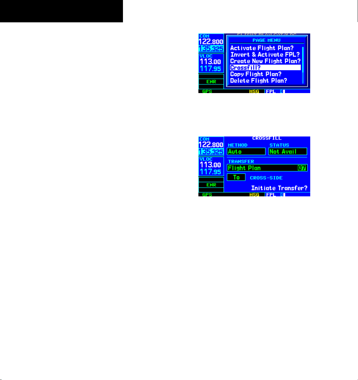
SECTION 5
FLIGHT PLANS
Flight Plan Catalog Options
The following options (some covered on the preceding
pages) are available for the Flight Plan Catalog Page:
• ‘Activate Flight Plan?’ - Allows the pilot to
select the flight plan for navigation guidance, as
described previously in this section.
• ‘Invert & Activate FPL?’ - Allows the pilot to
reverse the highlighted flight plan and select it for
navigation guidance, as described previously in
this section.
• ‘Create New Flight Plan?’ - Allows the pilot to
create a new flight plan, as described previously in
this section.
• ‘Crossfill?’ - Allows the pilot to transfer a Direct-to
destination, the active flight plan, any stored flight
plan or user waypoints to a second 400-Series or
500-Series Garmin unit. Some crossfill operations
can be done automatically. If both units are set
to ‘auto’, a change in the direct-to destination or
active flight plan on one unit is seen on the other.
For additional information, see Section 10.2,
Flight Planning Page: Crossfill.
To crossfill flight plans between two 400or 500-Series Garmin units:
1) Select the ‘Crossfill?’ option from the Flight
Plan Catalog Page Menu (Figure 5-12) and
press the ENT Key.
Figure 5-12 Flight Plan Catalog Page Menu
2) Turn the large right knob to select the
‘Method’ field (Figure 5-13).
Figure 5-13 Crossfill Page
3) Turn the small right knob to select ‘Auto’
or ‘Manual’ and press the ENT Key. ‘Auto’
automatically transfers the active flight plan
or Direct-to selection to another 400- or 500series Garmin unit, without user intervention.
4) If ‘Manual’ is selected: Turn the large right
knob to select the ‘Transfer’ field, then turn
the small right knob to select the type of
information to transfer between units (active
flight plan, flight plan, all user waypoints or
a single user waypoint). When ‘Flight Plan’
or ‘User Waypoint’ is selected, a second field
appears to the immediate right of the ‘Transfer’
field. Use the small and large right knobs to
enter the number of the flight plan or the name
of the user waypoint to be transferred.
5-6
GNS 430 Pilot’s Guide and Reference
Page 73

SECTION 5
FLIGHT PLANS
5) The ‘Cross-Side’ field allows the pilot to
designate the sending and receiving units
in a crossfill operation. Turn the large right
knob to select the ‘Cross-side’ field, then turn
the small right knob to select ‘To’ or ‘From’
(Figure 5-14). Press the ENT Key to confirm
the selection.
Figure 5-14 Transfer Window
6) Turn the large right knob to highlight ‘Initiate
Transfer?’ and press the ENT Key.
• ‘Copy Flight Plan?’ - Allows the pilot to copy the
selected flight plan to a new flight plan location,
as described previously in this section. The copy
function is useful for duplicating an existing flight
plan before making changes.
• ‘Delete Flight Plan?’ - Allows the pilot to remove
the selected flight plan from memory, as described
previously in this section. Deleting a flight
plan does not delete the individual waypoints
contained in the flight plan from the database or
user waypoint memory.
To delete all flight plans:
1) Select the ‘Delete All Flight Plans?’ option from
the Flight Plan Catalog Page Menu (Figure
5-15) and press the ENT Key.
Figure 5-15 Flight Plan Catalog Page Menu
2) A confirmation window appears (Figure 5-16).
With ‘Yes?’ highlighted, press the ENT Key.
Figure 5-16 Delete All Flight Plans Window
• ‘Delete All Flight Plans?’ - Allows the pilot to
remove all flight plans from memory.
GNS 430 Pilot’s Guide and Reference
5-7
Page 74

SECTION 5
FLIGHT PLANS
• ‘Sort List By Number?’/’Sort List by Comment?’
- Allows the pilot to select between a flight plan
catalog sorted numerically by the flight plan
number or sorted alphanumerically based upon
the comment assigned to each flight plan. When
either option is selected, the other option appears
on the Flight Plan Catalog Page Menu.
To sort the catalog listing by number or
comment:
1) Select the ‘Sort List By Number?’ or ‘Sort List
By Comment?’ option (whichever is currently
displayed) from the Flight Plan Catalog Page
Menu (Figure 5-17) and press the ENT Key.
Figure 5-17 Flight Plan Catalog Page Menu
5.2 ACTIVE FLIGHT PLAN PAGE
The Active Flight Plan Page provides information
and editing functions for ‘flight plan 00’, the flight plan
currently in use for navigation. When a direct-to or flight
plan has been activated, the Active Flight Plan Page shows
each waypoint for the flight plan (or a single waypoint
for a direct-to, Figure 5-18), along with the desired track
(DTK) and distance (DIS) for each leg.
Figure 5-18 Active Flight Plan Page
Active Flight Plan Options
The options shown in Table 5-1 are available for the
Active Flight Plan Page.
To access the Active Flight Plan Menu Page:
5-8
1) Press the FPL Key to view the Active Flight Plan
Page.
2) Press the
Figure 5-19 Active Flight Plan Page Menu
GNS 430 Pilot’s Guide and Reference
MENU Key (Figure 5-19).
Page 75

Active Flight Plan Page Menu Options
Activate Leg
Activates/reactivates the flight plan and selects the highlighted leg as the ‘active leg’ (the leg
which is currently used for navigation guidance).
Allows the pilot to transfer the active flight plan between two 400- or 500-series Garmin units
Crossfill
in a dual unit installation. See Section 10.2, Flight Planning: Crossfill for additional information
on this feature.
Copy Flight Plan
Invert Flight Plan
Copies the active flight plan to a flight plan catalog location, as described previously in this
section. The copy function is useful for duplicating the active flight plan before making changes.
Reverses the active flight plan. See Section 5.1, Activating Flight Plans and Inverting Flight
Plans.
Allows the pilot to remove all waypoints from the selected flight plan, as described previously
Delete Flight Plan
in this section. Deleting a flight plan does not delete the waypoints contained in the flight plan
from the database or user waypoint memory.
Allows the pilot to select a published instrument approach for the destination airport, or replace
Select Approach
the current approach with a new selection. (In many cases, it is convenient to select approaches
using the PROC Key as described in Section 6.1.)
Allows the pilot to select a published standard terminal arrival route (STAR) for the destination
Select Arrival
airport or replace the current arrival with a new selection (Section 6.1 for information on
selecting arrivals using the PROC Key).
Allows the pilot to select a published standard instrument departure (SID) for the departure
Select Departure
airport or replace the current departure with a new selection. When using a direct-to, the GNS
430 uses the nearest airport as a reference when displaying available departures. See Section
6.1 for information on selecting departures using the PROC Key.
Remove Approach Deletes the currently selected approach from the active flight plan.
Remove Arrival Deletes the current STAR from the active flight plan.
Remove Departure Deletes the current SID from the active flight plan.
Calculates the bearing and closest distance that a flight plan passes from a reference waypoint.
Closest Point of FPL
May also be used to create a new user waypoint along the flight plan at the location closest to
the reference waypoint.
Change Fields
Allows the pilot to select the desired data items to display on the Active Flight Plan Page, as
described in this Section.
Restore Defaults Returns the data items to factory defaults, as described in this Section.
SECTION 5
FLIGHT PLANS
Table 5-1 Active Flight Plan Page Menu Options
GNS 430 Pilot’s Guide and Reference
5-9
Page 76

SECTION 5
FLIGHT PLANS
The data fields for DTK and DIS are user-selectable and
may be changed to display cumulative distance (CUM) to
each waypoint, estimated time of arrival (ETA), estimated
time enroute (ETE), or enroute safe altitude (ESA).
To change a data field on the Active Flight
Plan Page:
1) With the Active Flight Plan Page displayed,
press the MENU Key to display the Active Flight
Plan Page Menu.
2) Turn the large right knob to highlight ‘Change
Fields?’ (Figure 5-20) and press the ENT Key.
Figure 5-20 Active Flight Plan Page Menu
To restore factory default settings for
data
fields on the Active Flight Plan Page:
1) With the Active Flight Plan Page displayed,
press the MENU Key to display the Active Flight
Plan Page Menu.
2) Turn the large right knob to highlight ‘Restore
Defaults?’ and press the ENT Key.
To activate a flight plan along a specific
leg:
1) Press the small right knob to activate the
cursor and turn the large right knob to
highlight the desired destination waypoint.
2) Press the
MENU Key, and select the ‘Activate
Leg?’ option from the Active Flight Plan Page
Menu (Figure 5-22) and press the ENT Key.
5-10
3) Turn the large right knob to highlight the field
to be changed.
4) Turn the small right knob to select the desired
data item (Figure 5-21) and press the ENT
Key.
Figure 5-21 Select Field Type Window
5) Press the small right knob to remove the
cursor.
GNS 430 Pilot’s Guide and Reference
Figure 5-22 Active Flight Plan Page Menu
3) A confirmation window appears. With
‘Activate?’ highlighted, press the ENT Key.
Page 77

SECTION 5
FLIGHT PLANS
To select an approach for a direct-to or
flight plan destination airport:
1) Choose the ‘Select Approach?’ option from the
Active Flight Plan Page Menu (Figure 5-23) and
press the ENT Key.
Figure 5-23 Active Flight Plan Page Menu
2) A window appears listing the available
approaches (Figure 5-24) for the destination
airport. Turn the small right knob to highlight
the desired approach and press the ENT Key.
3) A second window appears listing available
transitions (Figure 5-25) for the approach. Turn
the small right knob to highlight the desired
transition waypoint and press the ENT Key.
(The ‘Vectors’ option assumes the pilot will
receive vectors to the final course segment
of the approach and will provide navigation
guidance to intercept this final course.)
Figure 5-25 Transitions Window
4) Turn the large right knob to highlight ‘Load?’
or ‘Activate?’ and press the ENT Key. ‘Load?’
adds the approach to the flight plan without
immediately using the approach for navigation
guidance. This allows the pilot to continue
navigating the original flight plan until cleared
for the approach but keeps the approach
available for quick activation when needed.
Figure 5-24 Approach Window
5) For precision approaches, a reminder window
appears indicating that GPS guidance on such
approaches is strictly for monitoring only. To
confirm this reminder, highlight ‘Yes?’ and
press the ENT Key.
GNS 430 Pilot’s Guide and Reference
5-11
Page 78

SECTION 5
FLIGHT PLANS
To select an arrival for a direct-to or flight
plan destination airport:
1) Select the ‘Select Arrival?’ option from the
Active Flight Plan Page Menu (Figure 5-26)
and press the ENT Key.
Figure 5-26 Active Flight Plan Page Menu
2) A window appears listing the available arrivals
(Figure 5-27) for the destination airport. Turn
the small right knob to select the desired
arrival and press the ENT Key.
3) A second window appears listing available
transitions (Figure 5-28) for the arrival. Turn
the small right knob to highlight the desired
transition waypoint and press the
Figure 5-28 Transitions Window
ENT Key.
4) With ‘Load?’ highlighted, press the ENT Key.
To select a departure for the departure
airport:
1) Select the ‘Select Departure?’ option from the
Active Flight Plan Page Menu and press the
ENT Key.
2) A window appears listing the available
departures for the departure airport. Turn
the small right knob to select the desired
departure and press the ENT Key.
5-12
Figure 5-27 Arrivals Window
3) A second window appears listing available
transitions for the departure. Turn the small
right knob to highlight the desired transition
waypoint and press the ENT Key.
4) With ‘Load?’ highlighted, press the
GNS 430 Pilot’s Guide and Reference
ENT Key.
Page 79

SECTION 5
FLIGHT PLANS
To remove an approach, arrival, or
departure from the active flight plan:
1) Select the ‘Remove Approach?’, ‘Remove
Arrival?’, or ‘Remove Departure?’ option from
the Active Flight Plan Page Menu (Figure 5-29)
and press the ENT Key.
Figure 5-29 Active Flight Plan Page Menu
2) A confirmation window appears listing
the procedure to be removed. With ‘Yes?’
highlighted, press the ENT Key.
To determine the closest point, along the
active flight plan, to a selected waypoint:
1) Select the ‘Closest Point of
FPL?’ option from
the Active Flight Plan Page Menu (Figure 5-30)
and press the ENT Key.
2) A window appears with the reference waypoint
field highlighted. Use the small and large
right knobs to enter the identifier of the
reference waypoint and press the ENT Key.
3) A confirmation window appears for the
selected reference waypoint (Figure 5-31).
Press the ENT Key to accept the waypoint.
Figure 5-31 Closest Point of Flight Plan Window
4) The GNS 430 displays the bearing (BRG) and
distance (DIST) to the closest point along the
flight plan, from the selected reference waypoint.
To create a user waypoint at this location and
add it to the flight plan, highlight ‘Load?’ and
press the ENT Key. The name for the new user
waypoint is derived from the identifier of the
reference waypoint.
Figure 5-30 Active Flight Plan Page Menu
GNS 430 Pilot’s Guide and Reference
5-13
Page 80

SECTION 5
FLIGHT PLANS
Shortcuts
A number of shortcuts are available to save time when
using the Active Flight Plan Page. These shortcuts speed
the process of removing approaches, departures and
arrivals, and aid in selecting a specific flight plan leg for
navigation guidance.
On the preceding page, options to remove approaches,
departures, and arrivals were introduced. This process
may also be completed using the CLR Key, as described
below.
To remove an approach, departure or
arrival using the CLR Key:
1) With the Active Flight Plan Page displayed,
press the small right knob to activate the
cursor.
2) Turn the large
for the approach (Figure 5-32), departure, or
arrival to be deleted. Titles appear in light blue
directly above the procedure’s waypoints.
right knob to highlight the title
3) Press the CLR Key to display a confirmation
window (Figure 5-33).
Figure 5-33 Remove Approach Window
4) With ‘Yes?’ highlighted, press the ENT Key to
remove the selected procedure.
This same process may also be used to remove
individual waypoints from the active flight plan.
To remove a waypoint using the CLR Key:
1) With the Active Flight Plan Page displayed,
press the small right knob to activate the
cursor.
5-14
Figure 5-32 Highlight Item To Be Deleted
GNS 430 Pilot’s Guide and Reference
2) Turn the large right knob to highlight the
identifier for the waypoint to be deleted.
Identifiers appear in green text.
3) Press the
CLR Key to display a confirmation
window (Figure 5-34).
Figure 5-34 Remove Waypoint Window
4) With ‘Yes?’ highlighted, press the ENT Key to
remove the selected procedure.
Page 81

SECTION 5
FLIGHT PLANS
The ‘Activate Leg?’ option is discussed previously in
this section, which allows the pilot to specify which leg of
the flight plan is used for navigation guidance. A shortcut
also exists for this operation, using the Direct-to Key.
To activate a specific leg of the active flight
plan:
1) Press the small right knob to activate the
cursor and turn the large right knob to
highlight the desired destination waypoint
(Figure 5-35).
Figure 5-35 Destination Waypoint Highlighted
2) Press the Direct-to Key twice to display an
‘Activate Leg’ confirmation window (Figure
5-36).
When using instrument procedures, this feature can be
used not only to activate a specific point-to-point leg, but
to also activate the procedure turn portion of an approach,
follow a DME arc, or activate a holding pattern.
Any approach, departure, or arrival can be reviewed on
the appropriate airport page in the Waypoint Page Group
(Section 7.1).
To review a procedure while viewing a
flight plan page:
1) With a flight plan page displayed, press the
small right knob to activate the cursor.
2) Turn the large right knob to highlight the
procedure header (Figure 5-37) and press the
ENT Key to select the WPT Page Group.
Figure 5-37 Procedure Header Highlighted
Figure 5-36 Activate Leg Window
3) With ‘Activate?’ highlighted, press the ENT
Key.
GNS 430 Pilot’s Guide and Reference
5-15
Page 82

SECTION 5
FLIGHT PLANS
Blank Page
5-16
GNS 430 Pilot’s Guide and Reference
Page 83

SECTION 6
PROCEDURES
SECTION 6: PROCEDURES
6.1 APPROACHES, DEPARTURES AND
ARRIVALS
The GNS 430 allows the pilot to fly non-precision and
precision approaches to airports with published instrument
approach procedures. All available approaches are stored
on the Jeppesen NavData card, and are automatically
updated when the new card is inserted into the GNS 430.
Subscription information for NavData cards is included in
the GNS 430 package.
The Procedures Page (Figure 6-1) is displayed by
pressing the PROC Key. The Procedures Page provides
direct access to approaches, departures, and
based upon the active flight plan or direct-to destination.
In either case, the departure and destination airports must
have published procedures associated with them.
To select an approach, departure, or arrival:
1) Press the
Page.
2) Turn the large
Approach?’, ‘Select Departure?’ or ‘Select
Arrival?’ (Figure 6-1) and press the ENT Key.
PROC Key to display the Procedures
right knob to highlight ‘Select
arrivals,
3) A window appears listing the available
procedures (Figure 6-2). Turn the large right
knob to highlight the desired procedure
and press the ENT Key. (When a direct-to
destination is selected, departures are offered
for the nearest airport.)
Figure 6-2 Approach Window
4) A second window appears listing the available
transitions (Figure 6-3). Turn the large right
knob to highlight the desired transition waypoint
and press the ENT Key. (The approach ‘Vectors’
option assumes the pilot will receive vectors
to the final course segment of the approach
and will provide navigation guidance relative
to the final approach course.)
Figure 6-1 Procedures Page
GNS 430 Pilot’s Guide and Reference
Figure 6-3 Transitions Window
6-1
Page 84

SECTION 6
PROCEDURES
5) Turn the large right knob to highlight ‘Load?’
or ‘Activate?’ (approaches only) and press the
ENT Key. (‘Load?’ adds the procedure to the
flight plan without immediately using it for
navigation guidance. This allows the pilot to
continue navigating the original flight plan, but
keeps the procedure available on the Active
Flight Plan Page for quick activation when
needed.)
6) For precision approaches and some nonprecision approaches, a reminder window
appears indicating that GPS guidance on such
approaches is strictly for monitoring only; use
the VLOC receivers and external CDI (or HSI) for
primary navigation. To confirm this reminder,
highlight ‘Yes?’ and press the
ENT Key.
Not all approaches in the database are approved
for GPS use. When selecting an approach, a ‘GPS’
designation to the right of the procedure name (Figure
6-4) indicates the procedure can be flown using the GPS
receiver. Some procedures do not have this designation,
meaning the GPS receiver may be used for supplemental
navigation guidance only. ILS approaches, for example,
must be flown by tuning the VLOC receiver to the proper
frequency and coupling the VLOC receiver to the external
CDI (or HSI).
Once an approach is selected, it may be activated
for navigation from the Procedures Page. Activating the
approach overrides the ‘enroute’ portion of the active
flight plan, proceeding directly to the ‘approach’ portion
(for a full approach, directly to the initial approach fix).
Activating the approach also initiates automatic CDI
scaling transition as the approach progresses.
To activate an approach:
1) Press the
PROC Key to display the Procedures
Page (Figure 6-5).
2) Turn the large right knob to highlight ‘Activate
Approach?’ (Figure 6-5) and press the ENT
Key.
Figure 6-5 Procedures Page
6-2
Figure 6-4 ‘GPS’ Designations
GNS 430 Pilot’s Guide and Reference
Page 85

SECTION 6
PROCEDURES
Another Procedures Page option allows the pilot to
activate the final course segment of the approach. This
option assumes the pilot will receive vectors to the final
approach fix (FAF) and provides guidance to intercept the
final course, before reaching the FAF.
To activate the approach, with vectors to
final:
1) Press the
PROC Key to display the Procedures
Page.
2) Turn the large right knob to highlight ‘Activate
Vector-To-Final?’ (Figure 6-6) and press the
ENT Key.
Figure 6-6 Procedures Page
In many cases, it may be easiest to ‘Load’ the full
approach while still some distance away, enroute to the
destination airport. Later, if vectored to final, use the
steps above to select ‘Activate Vector-To-Final’—which
makes the inbound course to the FAF waypoint active.
Otherwise, activate the full approach using the ‘Activate
Approach?’ option.
6.2 NON-PRECISION APPROACH OPERATIONS
The GNS 430 provides non-precision approach
guidance using its built-in GPS receiver. The GPS receiver
can also be used as a supplemental aid for precision
approaches, but the localizer and glideslope receivers must
be used for primary approach course guidance.
Approaches designed specifically for GPS are often
very simple and don’t require overflying a VOR or NDB.
Many non-precision approaches have ‘GPS overlays’ to
let the pilot fly an existing procedure (VOR, VOR/DME,
NDB, RNAV, etc.) more accurately using GPS.
Many overlay approaches are complex (in comparison
to GPS-only approaches). The GNS 430 displays and
provides guidance through each leg of the approach,
automatically sequencing through each of these legs, up
to the missed approach point (MAP). Approaches may
be flown ‘as published’ with the full transition using any
published feeder route or initial approach fix (IAF), or
may be flown with a vectors-to-final transition.
NOTE: The following approach examples are
intended for instructional use only and are not
to be used for navigation.
GNS 430 Pilot’s Guide and Reference
6-3
Page 86

SECTION 6
PROCEDURES
‘Select’ and ‘Load’ the ap-
proach
Figure 6-7 Sample Approach
Select Destination
‘Activate’ the ap-
DO NOT USE FOR
NAVIGATION
proach
4) ‘Activate’ the full approach or vectors-to-final,
as appropriate. In some scenarios, it may be
more convenient to immediately activate the
approach and skip the ‘Load’ process outlined
in the preceding step 3. The GNS 430 provides
both options.
Approaches with Procedure Turns
The procedure turn portion of an approach is stored
as one of the legs of the approach. For this reason, the
GNS 430 requires no special operations from the pilot
(other than flying the procedure turn itself) beyond what
is required for any other type of approach.
Lynchburg (VA) Regional
VOR or GPS Rwy 03
6-4
Approach operations on the GNS 430 typically begin
with the same basic steps (refer to Figure 6-7 for the
following steps):
1) Select the destination airport using the Directto Key, or as the last waypoint in the active
flight plan.
2) Choose the ‘Select Approach?’ option from
the Procedures Page (Section 6.1) or from the
Active Flight Plan Page Menu (Section 5.2,
Active Flight Plan Options).
3) ‘Load’ the approach (often while enroute) in
anticipation of its future use. This places the
approach in the active flight plan, but retains
course guidance in the enroute section until
the approach is ‘activated’.
GNS 430 Pilot’s Guide and Reference
DO NOT USE FOR
NAVIGATION
Figure 6-8 Sample Approach with Procedure Turn
This example uses the VOR Runway 03 approach for
Lynchburg (Virginia) Regional Airport, KLYH, and assumes
a departure from Frederick (Maryland) Municipal Airport,
KFDK.
Page 87

SECTION 6
PROCEDURES
The steps required to set up and fly the approach
are detailed below (refer to Figure 6-8 for the following
steps):
1) Prior to departing KFDK, the destination (KLYH)
is selected using the Direct-to Key or by
creating a flight plan terminating at Lynchburg
Regional.
2) While enroute to KLYH, select the ATIS
frequency from the list on the NAV/COM Page
(Section 3.6 and Figure 6-9) and place it in
the standby field of the COM Window. Use
the COM Flip-flop Key to make the ATIS
frequency active.
Figure 6-9 NAV/COM Page
3) Press the PROC Key (Figure 6-10) and select
the ‘VOR 03’ approach using the steps outlined
in Section 6.1. From the Transitions Window
(Figure 6-11), select LYH VOR (the IAF). Also,
select ‘Load?’ to load, but not activate, the
approach.
Figure 6-10 Procedures Page
Figure 6-11 Approach and Transitions Windows
4) Press the PROC Key, select ‘Activate Approach?’
and press the ENT Key to activate the
approach.
GNS 430 Pilot’s Guide and Reference
6-5
Page 88

SECTION 6
PROCEDURES
Flying the Procedure Turn
DO NOT USE FOR
NAVIGATION
Figure 6-13 CDI Scale at 1.0 nm
2) Several miles prior to reaching the IAF (LYH),
the pilot may wish to review the approach
sequence. Press the FPL Key to display the
Active Flight Plan Page. Press the small right
knob, and then turn the large right knob to
review each segment of the approach (Figure
6-14). When finished, press the FPL Key again
to return to the previous page.
6-6
Figure 6-12 Sample Approach with Procedure Turn
Refer to Figure 6-12 for the following steps:
1) Within 30 nm of the destination airport, the
GNS 430 switches from ‘enroute’ mode to
‘terminal’ mode (as indicated in the lower left
corner of the screen). The switch to terminal
mode is accompanied by a gradual Course
Deviation Indicator (CDI) scale transition from
5.0 to 1.0 nm, full scale deflection (Figure
6-13).
GNS 430 Pilot’s Guide and Reference
Figure 6-14 Active Flight Plan Page
3) When approaching the IAF (LYH), a waypoint
alert (‘NEXT DTK 205°’) appears in the lower
right corner of the screen (Figure 6-15). As
the distance (DIS) to the IAF approaches zero,
the alert is replaced by a turn advisory (‘TURN
TO 205°’). Dial the outbound course of 205°
into the CDI (or HSI) using the OBS knob.
Page 89

Figure 6-15 Waypoint Alert
4) Fly the outbound course.
5) Approximately one minute after passing the
FAF (LYH), the alert message ‘START PROC
TRN’ appears in the lower right corner of the
screen. Initiate the procedure turn at any time
after receiving this alert message.
DO NOT USE FOR
NAVIGATION
SECTION 6
PROCEDURES
Refer to Figure 6-16 for the following steps:
6) Course guidance is provided relative to the
outbound leg from the FAF. No guidance
through the procedure turn itself is given. (The
procedure turn is displayed on the Map Page
and indicated as the active leg on the Default
NAV Page and the Active Flight Plan Page.) The
CDI needle starts moving to the right.
7) When turning to intercept the inbound course,
the GNS 430 sequences to the inbound leg to
the FAF, the CDI needle swings to the opposite
side to provide proper sensing along the final
course segment and ‘NEXT DTK 025°’ appears
in the lower right corner of the screen (Figure
6-17).
Figure 6-16 Terminal Mode
Figure 6-17 Sequence to Inbound Leg
8) Turn to the final approach course.
9) Within 2.0 nm of the FAF (LYH), the GNS 430
switches from terminal mode to ‘approach’
mode. CDI scaling is tightened from 1.0 to
0.3 nm, full scale deflection.
10) When approaching the FAF, a waypoint alert
(‘NEXT DTK 026°’) appears in the lower
right corner. Make any course adjustments
necessary for the final course segment (FAF to
MAP).
GNS 430 Pilot’s Guide and Reference
6-7
Page 90

SECTION 6
PROCEDURES
11) After crossing the FAF, the destination
sequences to the MAP (‘RW03’, the runway
threshold, see Figure 6-18). Fly toward the
MAP.
Figure 6-18 Sequence to MAP
NOTE: When viewing the Map Page, note that
the final course segment is displayed in magenta
(the active leg of the flight plan always appears
in magenta) and a dashed line extends the course
beyond the MAP. The dashed line is provided for
situational awareness only and should NOT be
used for navigation. Follow the published missed
approach procedures.
12) When approaching the MAP, a waypoint alert
(‘APPRCHING WPT’) appears in the lower right
corner.
Figure 6-19 ‘SUSP’ Annunciation
Flying the Missed Approach
After passing the MAP, if the runway isn’t in sight the
pilot must execute a missed approach. The GNS 430
continues to give guidance along an extension of the final
course segment (FAF to MAP) until the pilot manually
initiates the missed approach procedure (as mentioned
previously in reference to the ‘SUSP’ advisory).
6-8
13) After crossing the MAP, ‘SUSP’ appears above
the OBS Key (Figure 6-19), indicating that
automatic sequencing of approach waypoints
is suspended at the MAP. A ‘from’ indication
is displayed on the CDI and Default NAV Page,
but course guidance along the final approach
course continues. If a missed approach is
required, use the OBS Key to initiate the missed
approach sequence, as outlined, beginning on
the following page.
GNS 430 Pilot’s Guide and Reference
DO NOT USE FOR
NAVIGATION
Figure 6-20 Sequence to MAP
The OBS Key is used to initiate the missed approach,
as follows (refer to Figure 6-20 for the following steps):
Page 91

SECTION 6
PROCEDURES
1) Press the OBS Key. The missed approach
holding point (MAHP; in this case ‘SWARM’
intersection) is automatically offered as the
destination waypoint (Figure 6-21).
Figure 6-21 Missed Approach Holding Point
NOTE: In some cases, an additional hold
waypoint is added to the missed approach
sequence. This additional waypoint is used
as an aid in establishing the holding pattern,
especially where the MAP and MAHP are the
same waypoint.
2) Follow the missed approach procedures, as
published on the approach plate, for proper
climb and heading instructions. The GNS 430
guides the pilot to the holding pattern, along
the 053° radial from LYH VOR.
3) An alert message in the lower right-hand corner
of the screen recommends entry procedures for
the holding pattern (i.e., ‘HOLD DIRECT’, ‘HOLD
PARALLEL’, or ‘HOLD TEARDROP’, see Figure
6-22). When flying the holding pattern, a timer
appears on the Default NAV Page (Figure 6-23).
The timer automatically resets on the outbound
side of the hold when the aircraft is abeam the
hold waypoint. The timer again resets as the
aircraft turns inbound (within approximately
30° of the inbound course). This allows the
pilot to use standard timing (typically one
minute) to fly the inbound and outbound legs
of the hold.
Figure 6-22 ‘Hold Teardrop’ Annunciation
Figure 6-23 Hold Timer
4) The GNS 430 provides course guidance only
on the inbound side of the holding pattern.
When leaving the holding pattern to re-fly
the approach (or another approach) press the
PROC Key to ‘Select Approach?’ or ‘Activate
Approach?’ as previously described. (Or,
use the Direct-to Key to select another
destination.)
GNS 430 Pilot’s Guide and Reference
6-9
Page 92
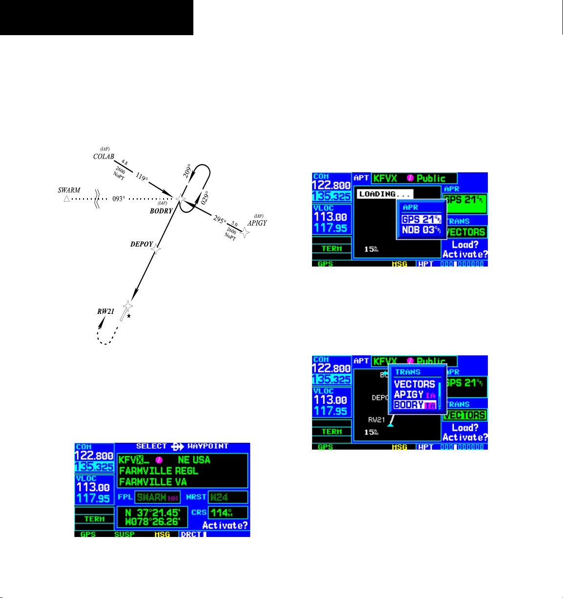
SECTION 6
PROCEDURES
Flying an Approach with a Hold
Starting where the previous example left off, assume
weather conditions resulted in a missed approach at
Lynchburg Regional. The pilot has decided to divert to
Farmville Regional (KFVX) instead (refer to Figure 6-24
for the following steps).
DO NOT USE FOR
NAVIGATION
Figure 6-24 Approach with Hold
3) Press the ENT Key twice.
This time, the pilot selects the GPS runway 21
approach into Farmville Regional. The GPS runway 21
approach begins with a holding pattern at the IAF, BODRY
intersection.
4) Press the PROC Key and select the ‘GPS 21’
approach. (Figure 6-26, also Section 6.1 for
additional instructions.)
Figure 6-26 Approach Window
5) From the Transitions Window, select BODRY
intersection as the IAF (Figure 6-27). Also,
select ‘Activate?’ to load and activate the
approach.
6-10
1) Press the Direct-to Key.
2) Use the small and large
right knobs to enter
the destination airport’s identifier (KFVX)
(Figure 6-25).
Figure 6-25 Select Direct-To Waypoint Page
GNS 430 Pilot’s Guide and Reference
Figure 6-27 TRANS ‘Transitions’ Window
6) Once the approach has been activated, the
Active Flight Plan Page appears (Figure 6-28).
The pilot may review the approach sequence
by pressing the small right knob and turning
the large right knob. Press the FPL Key to
return to the navigation pages.
Page 93

Figure 6-28 Active Flight Plan Page
SECTION 6
PROCEDURES
holding pattern entry (Figure 6-30). (‘HOLD
DIRECT’ or ‘HOLD PARALLEL’ may be offered
on other similar approaches.)
Figure 6-29 Terminal Mode
Refer to Figure 6-29 for the following steps.
7) As in the last example, within 30 nm of the
airport, the GNS 430 switches from enroute to
terminal mode, and the CDI scale transitions
from 5.0 to 1.0 nm, full scale deflection.
8) Just prior to crossing BODRY intersection, a
’HOLD TEARDROP’ alert appears in the lower
right corner of the screen to suggest the proper
DO NOT USE FOR
NAVIGATION
Figure 6-30 ‘HOLD TEARDROP’ Annunciation
9) As mentioned in the missed approach example,
the Default NAV Page displays a timer during
the holding pattern (Figure 6-31). The timer
can be used to fly the one minute outbound
portion of the holding pattern. (The holding
pattern is displayed on the Map Page and
indicated as the active leg on the Default NAV
Page and the Active Flight Plan Page.)
Figure 6-31 Default NAV Page
10) When crossing the IAF, ‘SUSP’ appears above
the OBS Key (Figure 6-31), indicating that
automatic sequencing of approach waypoints
is temporarily suspended. As the aircraft turns
inbound, ‘SUSP’ is cancelled and the GNS 430
returns to automatic sequencing.
GNS 430 Pilot’s Guide and Reference
6-11
Page 94

SECTION 6
PROCEDURES
NOTE: If the pilot needs to lose extra altitude
or speed by going around the holding pattern
again, press the OBS Key to manually suspend
waypoint sequencing BEFORE crossing the
holding waypoint the second time. If this
waypoint has already been passed, re-activate
the holding pattern using the steps described in
Section 5.2.
DO NOT USE FOR
NAVIGATION
Refer to Figure 6-32 for the following steps.
11) When approaching BODRY intersection, a
waypoint alert (’NEXT DTK 209°’) appears in
the lower right corner of the screen (Figure
6-33).
Figure 6-33 Waypoint Alert
12) At 2.0 nm from the FAF (DEPOY intersection),
the GNS 430 switches from terminal mode to
approach mode. CDI scaling is tightened from
1.0 to 0.3 nm, full scale deflection.
6-12
Figure 6-32 Approach Mode
GNS 430 Pilot’s Guide and Reference
Page 95

SECTION 6
PROCEDURES
13) When approaching the FAF, a waypoint alert
(‘NEXT DTK 209°’) appears in the lower
right corner (Figure 6-34). Make any course
adjustments necessary for the final course
segment (FAF to MAP).
Figure 6-34 Final Approach
14) After crossing the FAF, the destination sequences
to the MAP (‘RW21’, the runway threshold).
With the needle centered, fly toward the MAP,
observing the altitude minimums dictated by
the approach plate. When viewing the Map
Page, note that the final course segment is
displayed in magenta, (the active leg of the
flight plan always appears in magenta) and
a dashed line extends the course beyond the
MAP. Do not follow this extended course.
Instead, follow published missed approach
procedures.
15) When approaching the MAP, a waypoint alert
(‘APPRCHING WPT’) appears in the lower right
corner.
16) After crossing the MAP, ‘SUSP’ appears above
the OBS Key (Figure 6-35), indicating that
automatic sequencing of approach waypoints
is suspended at the MAP. A ‘from’ indication
is displayed on the CDI and Default NAV Page,
but course guidance along the final approach
course continues. If a missed approach is
required, use the OBS Key to initiate the
missed approach sequence, as outlined in this
section.
Figure 6-35 Missed Approach
GNS 430 Pilot’s Guide and Reference
6-13
Page 96

SECTION 6
PROCEDURES
Flying a DME Arc Approach
The GPS overlay for a DME arc approach uses
additional Jeppesen-provided waypoints to define the arc.
These waypoints are indicated by ‘D’ as the first letter in
the waypoint name. This is followed by three numbers
which indicate the radial the waypoint lies on. The last
letter indicates the radius of the arc.
Either of the following may be done to intercept the arc
for a DME arc approach:
• Follow a specified radial inbound to intercept the
IAF.
• Follow ATC vectors which allow the pilot to
intercept the arc at any point along the arc.
DO NOT USE FOR
NAVIGATION
This example is based upon a flight from Hutchinson
(Kansas) Municipal (KHUT) to Billard Municipal (KTOP)
in Topeka, Kansas. The VOR/DME runway 22 approach
is selected, along with ‘D258G’ as the IAF (refer to Figure
6-36 for the following steps).
1) Select Billard Municipal (KTOP) as the
destination via the Direct-to Key or as the
last waypoint in a flight plan (Figure 6-37).
Figure 6-37 Select Waypoint Page
2) Press the PROC Key (Figure 6-38) and select
the ‘VOR 22’ approach (Figure 6-39) using
the steps outlined in Section 6.1. From the
Transitions Window, select ‘D258G’ as the IAF.
Also, select ‘Load?’ (or ‘Activate?’, if already
cleared for the approach).
6-14
Figure 6-36 Enroute Mode
NOTE: As this manual was being written, the
letter/number DME arc names were being
replaced with standard five-letter intersection
names. Either naming convention may be used
for an approach.
GNS 430 Pilot’s Guide and Reference
Figure 6-38 Procedures Page
Page 97

SECTION 6
PROCEDURES
Figure 6-39 Approach Window
DO NOT USE FOR
NAVIGATION
Billard Muni (Topeka, KS)
VOR or GPS Rwy 22
Figure 6-40 Terminal Mode
Refer to Figure 6-40 for the following steps.
3) Within 30 nm of KTOP, the GNS 430 switches
from enroute mode to terminal mode and the
CDI scale transitions from 5.0 to 1.0 nm, full
scale deflection.
Figure 6-41 Procedures Page
5) When approaching the IAF (D258G), a waypoint
alert (‘NEXT DTK 353°’) appears in the lower
right corner of the screen (Figure 6-42). As the
distance (DIS) to the IAF approaches zero, the
alert is replaced by a turn advisory (‘TURN TO
353°’).
Figure 6-42 Waypoint Alert
6) Follow the arc, when the course select setting
and desired track differ by more than 10°, a
‘Set course to ###°’ message appears on the
Message Page.
4) If the approach has not yet been activated
(in step 2 above), do so when cleared for the
approach (Figure 6-41).
GNS 430 Pilot’s Guide and Reference
6-15
Page 98

SECTION 6
PROCEDURES
7) The next point in the approach is an intermediate
fix, labeled ‘D025G’. When approaching this
intermediate fix, a waypoint alert (‘NEXT DTK
205°’) appears in the lower right corner of the
screen (Figure 6-43). As the distance to this fix
approaches zero, the alert is replaced by a turn
advisory (‘TURN TO 205°’). Dial this course into
the CDI (or HSI) using the OBS knob.
Figure 6-43 Intermediate Approach Fix
8) At 2.0 nm from the FAF (TOP VOR), the GNS
430 switches from terminal mode to approach
mode. CDI scaling is tightened from 1.0 to 0.3
nm, full scale deflection.
Refer to Figure 6-44 for the following steps.
DO NOT USE FOR
NAVIGATION
Figure 6-44 Approach Mode
9) When approaching the FAF, ‘NEXT DTK 214°’
appears in the lower right corner of the screen
(Figure 6-45). Select this course on the CDI (or
HSI) using the OBS knob.
6-16
Figure 6-45 Final Approach Fix
GNS 430 Pilot’s Guide and Reference
Page 99

10) After crossing the FAF, the destination
sequences to the MAP (‘RW22’, the runway
threshold). With the needle centered, fly
toward the MAP, observing the altitude
minimums dictated by the approach plate.
When viewing the Map Page, note that the final
course segment is displayed in magenta (the
active leg of the flight plan always appears in
magenta) and a dashed line extends the course
beyond the MAP (Figure 6-46).
SECTION 6
PROCEDURES
Figure 6-47 ‘SUSP’ Annunciation
Vectors to Final
Take a second look at the ‘VOR 22’ approach into
Billard Municipal. Instead of following the DME arc, ATC
tells the pilot to expect vectors onto the final approach
course. There are several ways to select ‘vectors to final’
with the GNS 430. The first two options below normally
require the least workload to accomplish:
Figure 6-46 Final Course Segment
11) When approaching the MAP, a waypoint alert
(‘APPRCHING WPT’) appears in the lower right
corner.
12) Afer crossing the MAP, ‘SUSP’ appears above
the OBS Key (Figure 6-47), indicating that
automatic sequencing of approach waypoints
is suspended at the MAP. A ‘from’ indication
is displayed on the CDI and Default NAV Page,
but course guidance along the final approach
course continues. Do not follow this extended
course. Follow published missed approach
procedures using the
OBS Key to initiate the
missed approach sequence, as outlined in
‘Flying the Missed Approach’ in this section.
• When the approach is first selected, choose
‘VECTORS’ from the Transitions Window.
• Load a full approach (including the IAF from the
Transitions Window) as described in Section 6.1.
When cleared, press the
PROC Key and select
‘Activate Vectors-To-Final?’.
• Load the full approach as described in Section
6.1. Use the Direct-to Key (by pressing it twice)
from the Active Flight Plan Page to select the
desired leg of the approach.
GNS 430 Pilot’s Guide and Reference
6-17
Page 100

SECTION 6
PROCEDURES
To select ‘VECTORS’ from the Transitions
Window:
1) Select Billard Municipal (KTOP) as the
destination, using the Direct-to Key, or as the
last waypoint in a flight plan.
2) Press the
PROC Key and select the ‘VOR 22’
approach using the steps outlined in Section
6.1.
3) From the Transitions Window, select ‘VECTORS’
(Figure 6-48).
Figure 6-48 Transitions Window
4) Select ‘Load?’ (or ‘Activate?’, if already cleared
for the approach).
To activate vectors-to-final from the
Procedures Page:
1) Select Billard Municipal (KTOP) as the
destination, using the Direct-to Key or as the
last waypoint in a flight plan.
2) Press the
PROC Key and select the ‘VOR 22’
approach using the steps outlined in Section
6.1.
3) From the Transitions Window, select ‘D258G’
as the IAF (Figure 6-49). Also, select ‘Load?’.
Figure 6-49 Transitions Window
4) When cleared, press the PROC Key and select
‘Activate Vector-To-Final?’ (Figure 6-50).
Figure 6-50 Procedures Page
Flying the Vectors Approach
With ‘vectors to final’ selected, the CDI needle remains
off center until the aircraft is established on the final
approach course. With the approach activated, the Map
Page displays an extension of the final approach course in
magenta (magenta is used to depict the active leg of the
flight plan) and ‘VTF’ appears as part of the active leg on
the Default NAV Page (as a reminder that the approach
was activated with vectors-to-final).
6-18
GNS 430 Pilot’s Guide and Reference
 Loading...