

Page 1
ACTV STBY
NAVWPTRTENRSTSQ
MSG
CLR ENT
CRSR
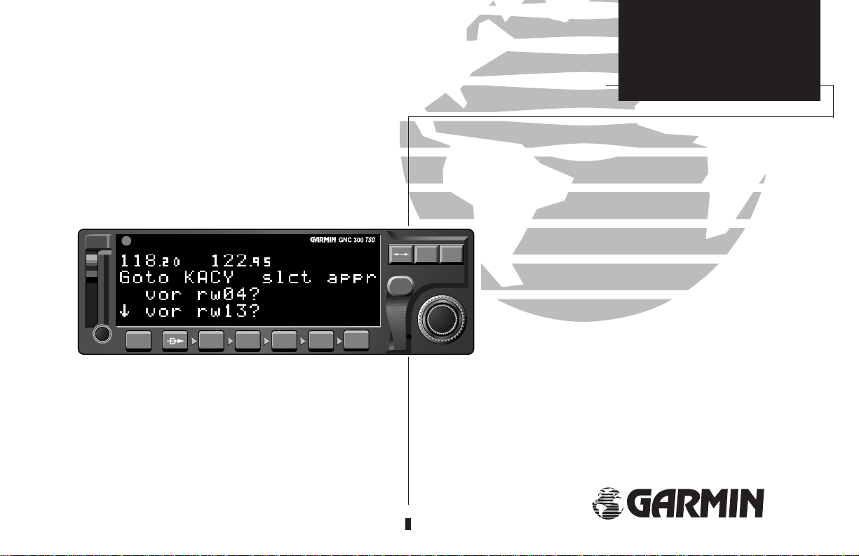
OWNER’S MANUAL
& REFERENCE
TM
GNC 300
Pilot’s Guide
®
Page 2

Page 3

Software Version 2.04 or above
© 1996 GARMIN Corporation
1200 East 151st Street, Olathe, KS 66062, USA
INTRODUCTION
Foreword
GARMIN (Europe) LTD, Unit 5, The Quadrangle, Abbey Park Industrial Estate,
Romsey, U.K. SO51 9AQ
All rights reserved. No part of this manual may be reproduced or transmitted in any
form or by any means, electronic or mechanical, including photocopying and recording, for any purpose without the express written permission of GARMIN.
Information in this document is subject to change without notice. GARMIN reserves
the right to change or improve their products and to make changes in the content of
this material without obligation to notify any person or organization of such changes
or improvements.
May 1996 190-00067-00 Rev. A Printed in USA
GARMIN™, GNC 300™, AutoLocate™,
MultiTrac8™, Spell’N’Find™, GPSCOM™
and AutoStore™ are trademarks of GARMIN
Corporation and may only be used with permission.
All rights reserved.
i
Page 4

INTRODUCTION
Cautions
CAUTION
The Global Positioning System is operated by the United States government,
which is solely responsible for its accuracy and maintenance. The system is subject to
changes which could affect the accuracy and performance of all GPS equipment.
Although the GARMIN GNC 300 is a precision electronic NAVigation AID (NAVAID),
NOTE: This device complies with Part 15 of the FCC
limits for Class B digital devices. This equipment generates, uses, and can radiate radio frequency energy and, if
not installed and used in accordance with the instructions, may cause harmful interference to radio communications. Furthermore, there is no guarantee that interference will not occur in a particular installation.
If this equipment does cause harmful interference, the
user is encouraged to try to correct the interference by relocating the equipment or connecting the equipment to a different circuit than the affected equipment. Consult an
authorized dealer or other qualified avionics technician for
additional help if these remedies do not correct the problem.
Operation of this device is subject to the following
conditions: (1) This device may not cause harmful interference, and (2) this device must accept any interference
received, including interference that may cause undesired
operation.
The GARMIN GNC 300 does not contain any userserviceable parts. Repairs should only be made by an
authorized GARMIN service center. Unauthorized repairs
or modifications could void your warranty and authority
to operate this device under Part 15 regulations.
ii
any NAVAID can be misused or misinterpreted and therefore, become unsafe.
Use the GNC 300 at your own risk. To reduce the risk of unsafe operation,
carefully review and understand all aspects of this Owner’s Manual and thoroughly
practice using the simulator mode prior to actual use. When in actual use, carefully
compare indications from the GNC 300 to all available navigation sources, including
the information from other NAVAIDS, visual sightings, charts, etc. For safety, always
resolve any discrepancies before continuing navigation.
The altitude calculated by the GNC 300 is geometric height above mean sea level
and could vary significantly from altitude displayed by pressure altimeters in aircraft.
Never use GPS altitude for vertical navigation.
The Jeppesen database incorporated in the GNC 300 must be updated regularly
in order to ensure that its information is current. Updates are released every 28 days.
A database information packet is included in your GNC 300 package.
Pilots using an out-of-date database do so entirely at their own risk.
Page 5

Accessories & Packing List
Congratulations on choosing the finest, most full-featured panel mount IFR GPS
COM available. The GNC 300 represents GARMIN’s commitment to provide an accurate, easy-to-use GPS for all of your aviation needs.
Before installing and getting started with your unit, please check to see that your
package includes the following items. If any parts are missing or damaged, please see
your GARMIN dealer immediately.
INTRODUCTION
Accessories and
Packing List
Standard Package:
• GNC 300 unit & NavData® Card
• GPS Antenna
• Aviation Installation Kit
• Pilot’s Guide & Quick Reference Guide
• Database Subscription Packet
• Warranty Registration Card
Optional Accessories
• AC Adapter
• Personal Computer Interface Kit
• User Data Card
• 28 to 14 volt DC converter
• MD-41 External Switch/Annunciator
To obtain accessories for your GNC 300,
please contact your nearest GARMIN dealer.
iii
Page 6

INTRODUCTION
Warranty
To obtain warranty service, see your local
dealer or call the GARMIN Customer Service
department for a returned merchandise
tracking number. The unit should be securely
packaged with the tracking number clearly
marked on the outside of the package, and
sent freight prepaid and insured to a
GARMIN authorized warranty service
facility.
Every GARMIN GPS is built to exacting standards to provide years of
trouble-free service. GARMIN warrants this product to be free from defects
in materials and workmanship for one year from the date of purchase.
GARMIN International, Inc. will at its sole option, repair or replace any
components which fail in normal use. Such repairs or replacement will be
made at no charge to the customer for parts or labor. The customer is, however, responsible for any transportation costs. This warranty does not cover
failures due to abuse, misuse, accident or unauthorized alteration or repairs.
GARMIN International, Inc. assumes no responsibility for special, incidental,
punitive or consequential damages, or loss of use.
THE WARRANTIES AND REMEDIES CONTAINED HEREIN ARE
EXCLUSIVE, AND IN LIEU OF ALL OTHER WARRANTIES EXPRESSED OR
IMPLIED, INCLUDING ANY LIABILITY ARISING UNDER WARRANTY OF
MERCHANTABILITY OR FITNESS FOR A PARTICULAR PURPOSE,
STATUTORY OR OTHERWISE. THIS WARRANTY GIVES YOU SPECIFIC
LEGAL RIGHTS, WHICH MAY VARY FROM STATE TO STATE.
iv
Page 7

PART ONE: INTRODUCTION
Foreword . . . . . . . . . . . . . . . . . . . . . . . . . . . . . . . . . . . . . . . . . . . . . . . . . .i
Cautions . . . . . . . . . . . . . . . . . . . . . . . . . . . . . . . . . . . . . . . . . . . . . . . . . .ii
Accessories/Packing List . . . . . . . . . . . . . . . . . . . . . . . . . . . . . . . . . . . . . . .iii
Capabilities . . . . . . . . . . . . . . . . . . . . . . . . . . . . . . . . . . . . . . . . . . . . . . . .iv
Table of Contents . . . . . . . . . . . . . . . . . . . . . . . . . . . . . . . . . . . . . . . . . .v-vi
Key and Knob Functions . . . . . . . . . . . . . . . . . . . . . . . . . . . . . . . . . . .vii-viii
GNC 300 Takeoff Tour . . . . . . . . . . . . . . . . . . . . . . . . . . . . . . . . . . . . . .1-8
PART TWO: REFERENCE
Section 1: Navigation with the GNC 300 ( Nkey) . . . . . . . . . . . . . . . . . .9
Navigating and planning functions
Section 2: Communicating with the GNC 300 . . . . . . . . . . . . . . . . . . . . .29
Using the GNC 300’s radio
Section 3: Waypoint and Database Information ( Wkey) . . . . . . . . . . . .32
Finding and using database and waypoint information
Section 4: Nearest Waypoints ( Tkey) . . . . . . . . . . . . . . . . . . . . . . . . .53
Finding nearest waypoints, SUAs and FSS frequencies
INTRODUCTION
Table of Contents
To quickly and easily locate
information on specific tasks, please refer to
the Index on page 125.
Section 5: Direct-to & Route Navigation ( Rkey) . . . . . . . . . . . . . . . . .58
Creating and using routes
Section 6: Approaches, SIDs & STARs ( Rkey) . . . . . . . . . . . . . . . . . . .72
Selecting and flying non-precision approaches
v
Page 8

INTRODUCTION
Table of Contents
Section 7: Messages and Unit Settings ( Mkey) . . . . . . . . . . . . . . . . . .95
Appendix A: NavData®and User Data Card Use . . . . . . . . . . . . . . . .104
Appendix B: Installation, Removal and Maintenance of the GNC 300 .106
Appendix C: Simulator . . . . . . . . . . . . . . . . . . . . . . . . . . . . . . . . . . .107
Appendix D: GNC 300 Abbreviations and Messages . . . . . . . . . . . . . .109
Appendix E: Specifications . . . . . . . . . . . . . . . . . . . . . . . . . . . . . . . . .117
Appendix F: Map Datums . . . . . . . . . . . . . . . . . . . . . . . . . . . . . . . . .118
Appendix G: Troubleshooting/Q & A . . . . . . . . . . . . . . . . . . . . . . . . .121
Appendix H: Index . . . . . . . . . . . . . . . . . . . . . . . . . . . . . . . . . . . . . .127
GARMIN is fully committed to your satisfaction as a customer. If you have any
questions regarding the GNC 300, please contact our customer service department at:
GARMIN International, Inc.
1200 East 151st Street
Olathe, KS 66062
vi
(913) 397-8200
FAX (913) 397-0836
Page 9

INTRODUCTION
B
Q
D
T
R
W
Key and Knob Functions
The power/volume knob controls unit power and radio volume.
The squelch button activates automatic squelch control.
The direct-to key performs an instant direct-to, allows you to enter a
waypoint, and sets a direct course to the destination.
The nearest key is used to obtain information on the 9 nearest airports,
VORs, NDBs, intersections, user waypoints and 2 nearest FSSs.
The nearest key also accesses any active SUA information.
See Section 4 for more information on the nearest waypoints.
The route key enables you to create, edit, activate and invert routes.
Approach, search-and-rescue, parallel offset and closest point of approach
are also performed using the route key. (Sections 5 and 6 for more information on routes).
The waypoint key is used to view information such as runways, frequencies, position and comments on airports, VORs, NDBs, intersections and
user waypoints. (See Section 2 for more information on the database).
Key and Knob
Functions
N
The navigation key is used to view navigation and position information.
Planning operations are also performed using the Nkey. (See Section 1
for more information on navigation and planning operations).
vii
Page 10

INTRODUCTION
Key and Knob
Functions
C
The cursor key is used to activate or deactivate the cursor in the separate
areas of the GNC 300. Pressing Conce will activate the cursor in the
comm ‘window’ and enable the pilot to change frequencies. Pressing
again will activate the cursor in the nav window (indicated by flashing
characters in a nav window field). It is used to highlight fields for data
entry, changing information, or cycling through available options.
C
viii
This manual will describe entering data using the
K
and Oknobs. Experiment with them and become
efficient in entering data with the concentric knobs.
This will greatly reduce the amount of time required
to navigate with the GNC 300.
The GNC 300 is designed to minimize
keystrokes when performing operations. There
are typically several ways to perform the
same operation. In general, using the knobs
will decrease keystrokes and time spent using
the GNC 300. Experiment to find the most
effective way to use the GNC 300 to your
advantage.
@
\
M
E
O
K
The arrow key flip-flops the active and standby frequencies.
The clear key is used to erase information or cancel an entry.
The status key is used to view receiver and satellite status, as well as
system messages. The Mkey is also used to access the GNC 300’s
settings.(See Appendix A for more information on receiver status).
The enter key is used to approve an operation or complete data entry.
It is also used to confirm information, such as during power on.
The outer knob is used to advance through pages, advance the cursor,
or move through data fields.
The inner knob us used to change data or scroll through information that
cannot fit on the screen all at once.
Page 11
The GARMIN GNC 300 is a powerful navigational tool that provides pilots with accurate navigational data and communication capability, along with non-precision approach certification in the
IFR environment. The Takeoff Tour is designed to familiarize you with the operation of the GNC
300, including powering up the unit, changing frequencies, entering data and performing a simple direct-to, and a limited introduction to the ‘Nearest’ functions. In addition, this section also
briefly covers the position, CDI and frequency pages available from the NAV key. These pages will
be used for most of your in-flight navigation.
The Takeoff Tour assumes that the GPSCOM and antennas have been properly installed
and you have not changed any of the GNC 300’s default settings. If you have changed any
of the factory default settings (position format, units of measure, selectable fields, etc.), the
pictures used may not match your configuration. Prior to using your GNC 300 for the first
time, we recommend that you taxi to a location that is well away from buildings and other
aircraft so the unit can collect satellite data without interruption.
Powering up the GNC 300
The GNC 300’s power and volume are controlled using the B(power/volume) knob at the
bottom left of the unit. Rotating it clockwise will turn the unit on and increase the radio volume. This knob also locks the NavData® card (included with your unit) in place so that it may
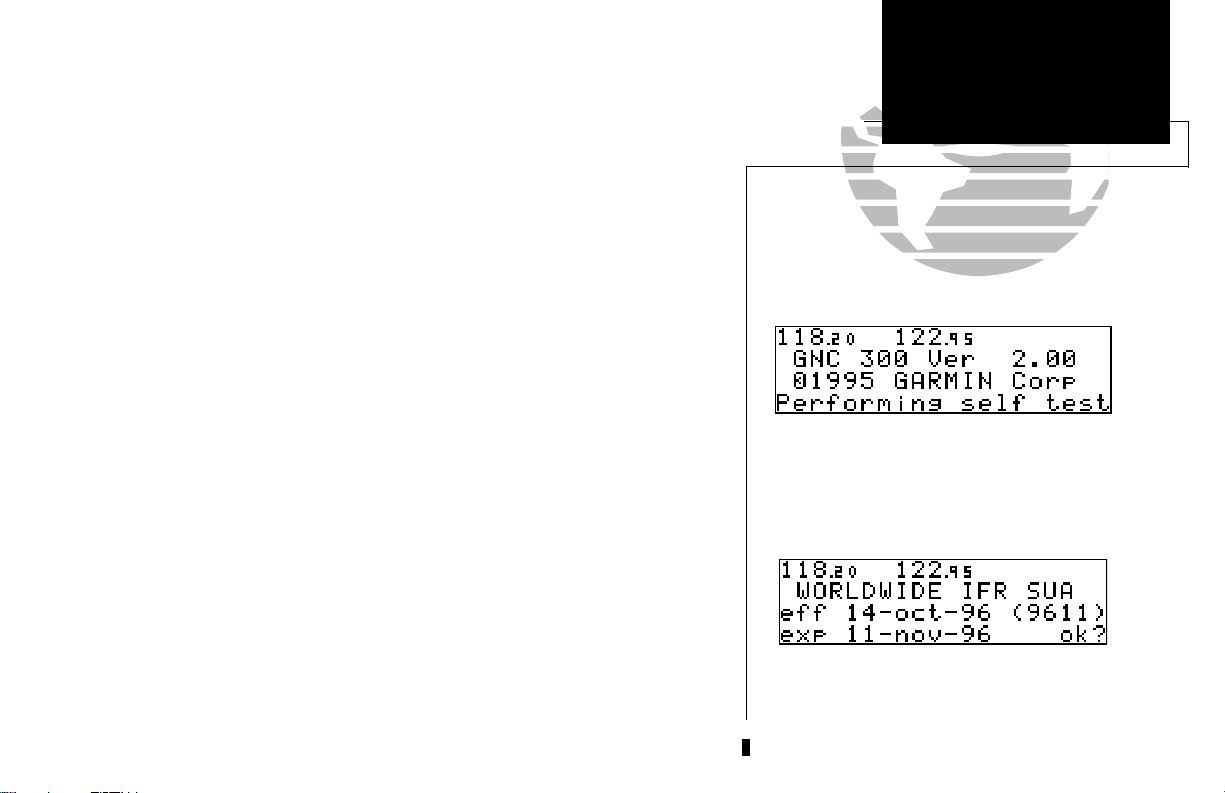
not be removed during operation. After turning the unit on, a welcome page will be displayed
while the unit performs a self test.
The database page will appear, showing the current database information on the NavData
card, with the valid operating dates, cycle number and database type indicated. Databases are
updated every 28 days and are available for one-time or subscription purchase.
To acknowledge the database information:
E key
1. Press the
.
TAKEOFF TOUR
Power On
Welcome Page
Database Confirmation Page
1
Page 12
TAKEOFF TOUR
Acquiring Satellites
Satellite Status Page
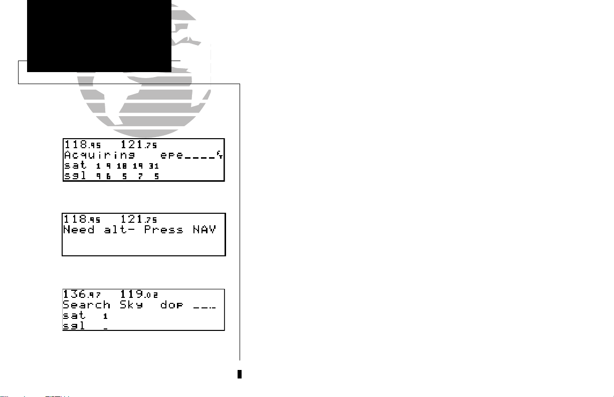
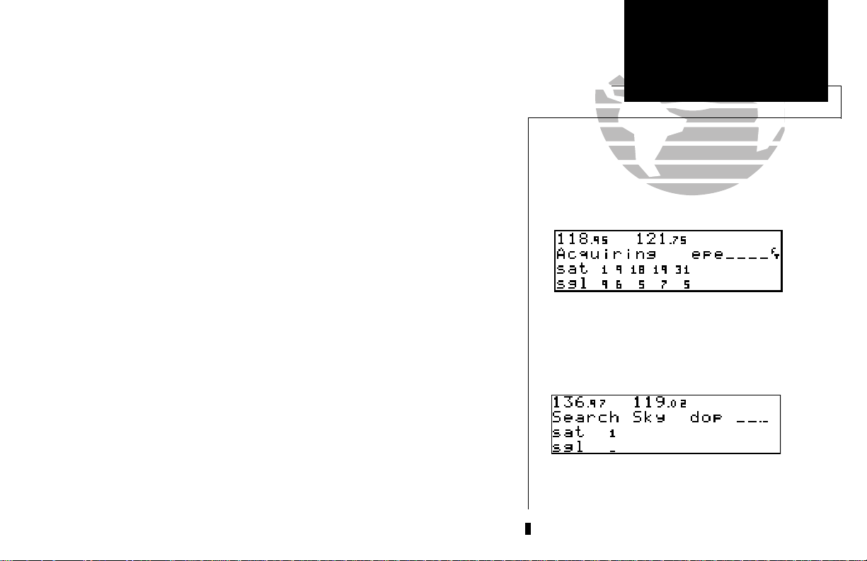
Once the database has been acknowledged, the satellite status page will appear,
and the GNC 300 will begin to collect satellite information. An ‘Acquiring’ status will
be displayed on the Satellite Status page, and the signal values on the bottom line of
the page will begin displaying numeric values. This is a good indication that you are
receiving signals, and satellite lock will occur. Following the first-time use of your
GNC 300, the time required for a position fix will vary- usually from 2 to 5 minutes.
If the unit can only obtain enough satellites for 2D navigation (no altitude), the
unit will use the altitude provided by your altitude encoder (if one is connected and
working). If not, you will be prompted to enter the altitude with a ‘Need alt- Press
NAV’ message. If this message occurs, press the Nkey and use the Kand
O
knobs to enter the altitude shown on your altimeter. Press Ewhen finished.
If the GNC 300 has not been operated for a period of six months or has moved
over 300 miles without actively tracking satellites, it may have to ‘Search the Sky’ to
collect new data. This means the unit is acquiring satellite data to establish almanac
and satellite orbit information, which can take 7 1/2 to 30 minutes. The Status page
will display a ‘Searching the Sky’ status, and the message annunciator (
M
key, will also flash to alert you of a system message.
U
), next to the
Enter the altitude manually if necessary.
To view a system message
1. Press M.
:
The message page will appear and display the status or warning information
applicable to the receiver’s current operating condition.
Searching the Sky
2
To return to the previous page after viewing a message
1. Press M.
:
Page 13
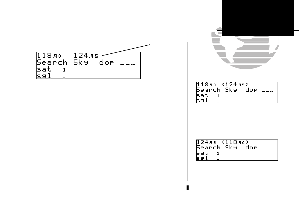
While the GNC 300 is acquiring a position, let’s take a minute to dial in the active
and standby frequencies you’ll be using for the first phase of your flight. The GNC
300’s display can be broken down into two separate ‘windows’, the comm window
(the top line of the display) and the GPS window (the bottom three lines of the
display).
Comm Window
TAKEOFF TOUR
Selecting Comm Frequencies
{
{
The Ckey is used to activate the cursor in a particular window (see right) to
provide access to various comm and navigation features. To select the active frequency,
you must first enter the frequency in the standby field, and use the @key to move it
to the active field.
To change the standby communication frequency:
1. Press Conce to activate the cursor in the comm window.
2. Rotate the outer knob (
the desired frequency.
To place the standby frequency in the active field, press
Once you’ve entered the active frequency, simply repeat steps 1 and 2 to enter the
standby frequency. After both frequencies have been entered, you may elect to keep
the comm window ‘hot’ by leaving the cursor on the standby frequency, or remove the
cursor by pressing the Ckey twice.
O
) to select the MHz, and the inner knob (K) to select the kHz of
}
GPS Window
}
@
.
Status page with cursor active in comm window.
Switching the active and standby frequencies will
not remove the cursor from the comm window.
3
Page 14
TAKEOFF TOUR
Position Page
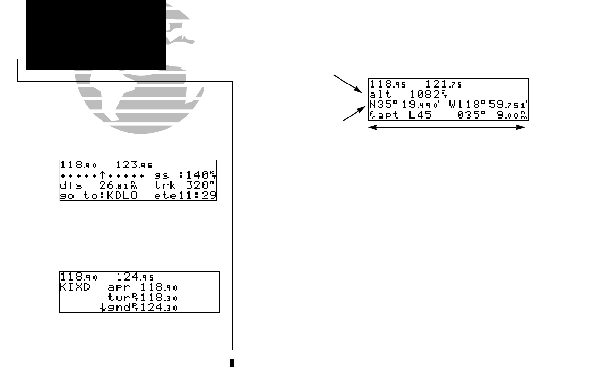
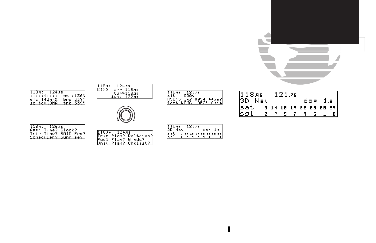
The CDI page with active destination.
NAVCOM Page
After the GNC 300 acquires satellites and computes a position, the position page will appear
automatically, and you’ll be informed with a ‘Ready for navigation’ message on the message page.
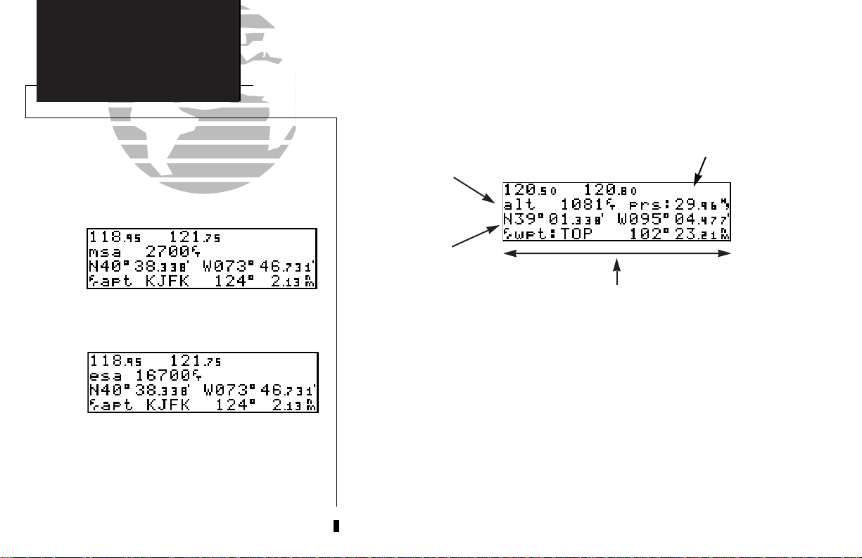
Altitude, MSA or ESA
Position (lat/lon)
Proximity Field
The position page displays your present latitude and longitude, altitude and a reference waypoint field; and is also used to enter the altimeter setting during approach operations. The altitude
and reference waypoint fields are also selectable (see Section 1 for more information) to allow you
to configure the unit to your own preferences. The default settings are:
• Altitude— Your present GPS altitude
• Present Position— Latitude and longitude displayed in degrees/minutes
• Reference Waypoint— The bearing and distance to the nearest airport
The position page is one of six pages available under the GNC 300’s NAV key:
• CDI page • NAVCOM page
• Position page • Satellite status page
• NAV menu 1 • NAV menu 2
During most flights, the position, CDI (course deviation indicator) and NAVCOM pages will be
the primary pages used for navigation. The pages available under each key are accessible by press-
4
ing the desired key and rotating the outer knob, or by pressing theNkey repeatedly.
Page 15
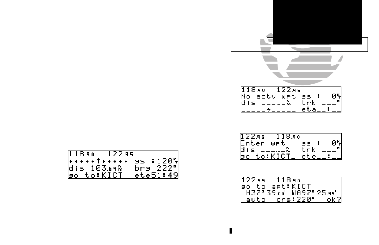
The GNC 300 uses direct point-to-point navigation to guide you from takeoff to
touchdown in the IFR environment. Once a destination is selected, the unit will provide speed, course and distance data based upon a direct course from your present
position to your destination. A destination can be selected from any page with the
direct-to (D) key.
To select a direct-to destination:
D
1. Press the
key. The CDI page will appear with the destination field flashing.
TAKEOFF TOUR
Direct-To Navigation
2. Rotate the
nation waypoint may be an airport, VOR, NDB, intersection or user waypoint, as long as it
is in the database or stored in memory as a user waypoint.
3. Rotate the
4. Repeat steps 2 and 3 to spell out the rest of the waypoint identifier.
5. Press
6. Press
K
knob to enter the first letter of the destination waypoint identifier. The desti-
O
knob to the right to move the cursor to the next character position.
E
to confirm the identifier. The direct-to confirmation page will appear (see right).
E
to confirm the destination.
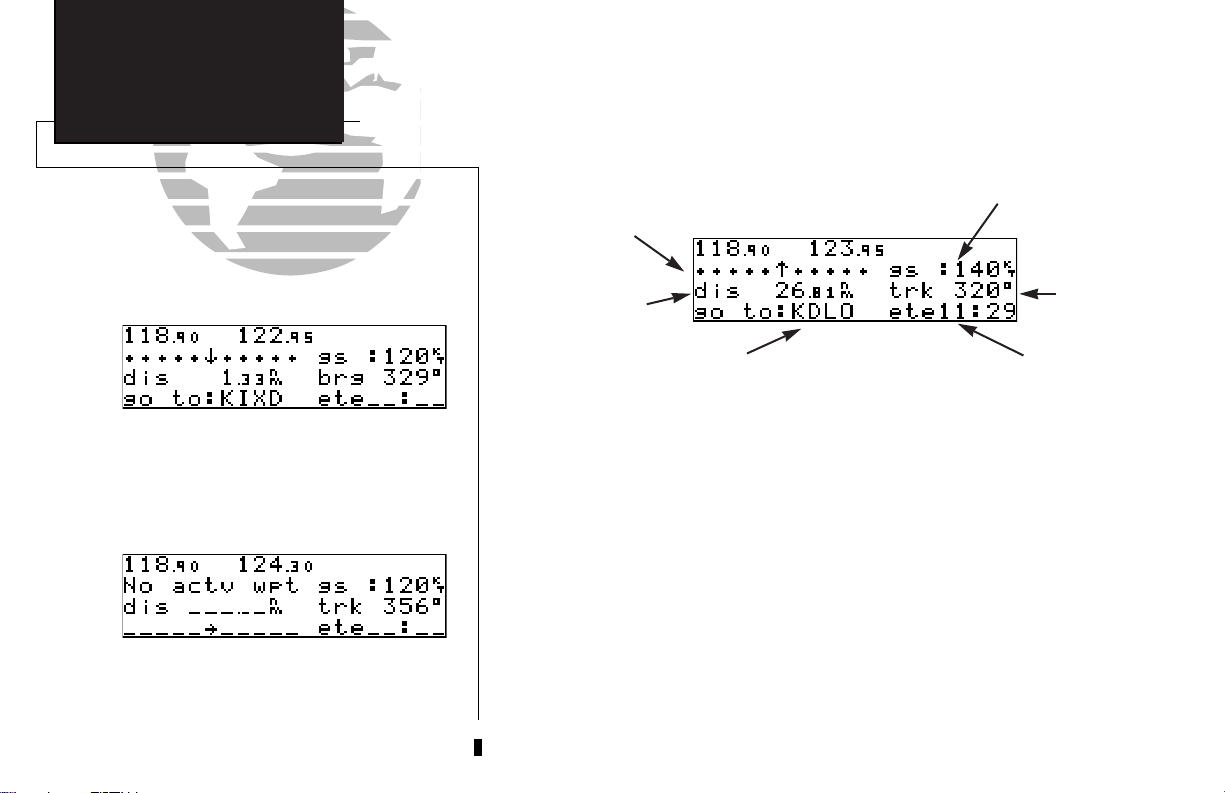
Once the direct-to destination is confirmed, the CDI page will appear with the
destination indicated in the lower left hand corner of the screen. Your present speed
and track over the ground, and the distance and estimated time enroute to your destination are also displayed. The graphical CDI, located at the top left of the screen, displays your position relative to the desired course and provides turn anticipation and
waypoint messages during route navigation.
The CDI page without a direct-to destination.
Entering the direct-to waypoint identifier.
The direct-to confirmation page allows you to
verify the destination’s latitude/longitude, facility
name or city/region by highlighting the position
field and rotating the INNER knob.
5
Page 16
REFERENCE
TAKEOFF TOUR
Nearest Airport Info &
NAVCOM Page
Navigation Diagram
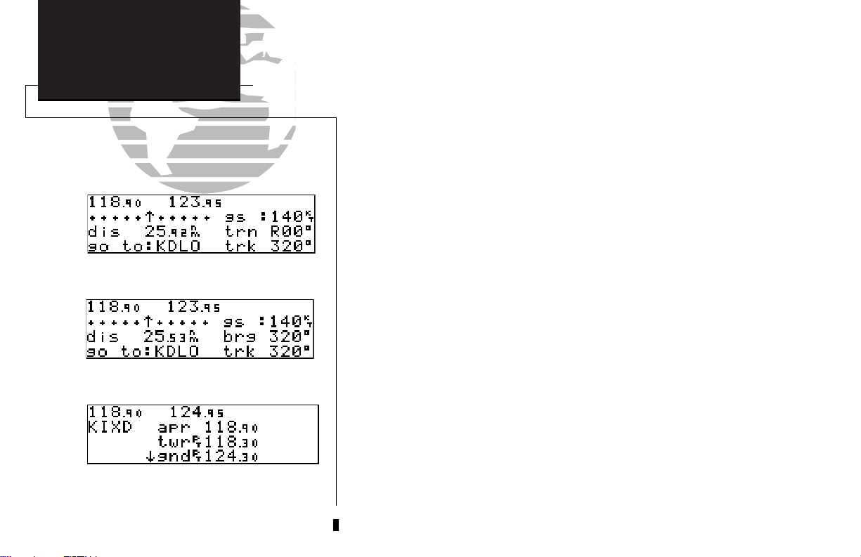
CDI page with ‘trn’ and ‘trk’ displayed.
In addition to the destination field and graphical CDI, the GNC 300 CDI page features four selectable fields for various navigation data so that the page may be configured to your own preferences (see Section 1 for more information). The default settings for the CDI page are:
• Ground Speed (gs)— Your present speed over the ground in knots
• Distance (dis)— The distance to your destination in nautical miles
• Track (trk)— Your present course over the ground
• Estimated Time Enroute (ete)— The time to your destination based
upon your present speed and course in hours and minutes
The next page available under the GNC 300’s NAV key is the navigation commu-
nications (NAVCOM) page. It provides you with a complete list of airport frequencies at your departure and arrival airports, allowing convenient selection of every frequency you’ll need along your flight path. If you do not have an active direct-to destination, the navigation communications page will display the frequencies for the airport
nearest your present position.
To view the NAVCOM page from the CDI page, rotate Oone stop to the right.
CDI page with ‘brg’ and ‘trk’ displayed.
NAVCOM Page
6
The NAVCOM page lists your departure and arrival airports on the left side of the
page, with all the database frequencies listed in a column down the right side of the
page. To scroll through the list of frequencies, simply rotate the inner knob (K) in the
direction of the arrow prompts at the bottom left of the page.
To place a frequency from the list in the standby field:
1. Press the
2. Use the
C
key twice to activate the cursor in the GPS window.
O
knob to select the desired frequency. Press Eto place the frequency in the
standby field. The cursor will automatically advance to the next frequency on the list.
Page 17
Once a direct-to is activated, the CDI page will provide navigation to the destina-
tion until the direct-to is cancelled or another direct-to destination is activated.
To cancel a direct-to from the CDI page:
TAKEOFF TOUR
Cancelling a Direct-To/
Nearest Waypoints
1. Press the
2. Press
3. Press
C
key twice to activate the cursor in the destination field.
\
.
E
.
The GNC 300’s NRST key provides the nine nearest airports, VORs, NDBs, inter-
sections and user waypoints, as well as the two closest FSSs (Flight Service Stations)
and any SUA (special use airspace) alerts for your present position. The nearest waypoint feature is a handy safety feature that may be used to execute a quick direct-to in
case of an in-flight emergency or to review the closest facilities to your present position.
The nearest feature can also be used to quickly find the contact frequency of the nearest airport and enter it in the standby field.
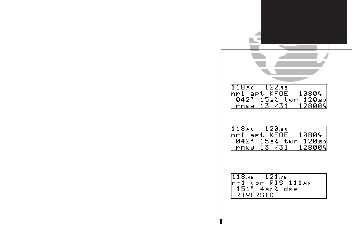
To view the nine nearest airports
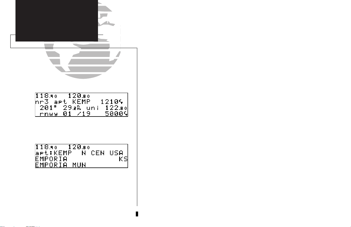
1. Press the Tkey. The nearest airport will be displayed, with elevation, frequency
and runway data.
2. To review the rest of the nearest airport list, rotate the
To place a nearest airport frequency in the standby field
1. PressE. Press the @key to place the frequency in the active field.
To view the nine nearest list for other waypoint categories (VOR, NDB, etc.)
1. Rotate the Oknob to the right, or press the Tkey repeatedly.
:
K
knob to the right.
:
:
Nearest Airport Page
To place a nearest airport frequency in the standby field, press ENTER.
Nearest VOR Page
2. Rotate Kto scroll through the list.
7
Page 18
REFERENCE
TAKEOFF TOUR
Nearest Airports
Satellite Acquisition
Shutting Down
Once the nearest airport (or any other nearest waypoint) page is displayed, the
selected waypoint can be quickly reviewed or selected as a direct-to destination.
To review the selected waypoint from the nearest waypoint list
1. Press Ctwice to activate the waypoint field.
2. Press Eto display the waypoint identification page.
3. Rotate Oto view any additional waypoint information available.
4. Press Tto return to the nearest waypoint page.
:
To select a nearest waypoint as a direct-to destination
1. Press the Dkey. The direct-to confirmation page for the selected waypoint will appear.
2. Press Eto confirm.
Third Nearest Airport Page
To review a nearest waypoint, highlight the identifier and press ENTER.
8
Congratulations! You’ve now gone through the basic operation of the GNC 300.
We encourage you to experiment with your new GPSCOM to get to know all the
advanced navigation features it has to offer. If you’d like a little more practice, try
using the built-in simulator described in Appendix C. An optional AC adapter will
even let you plan and simulate flights in the comfort of your home or office.
To turn the GNC 300 off:
B
1. Turn the
knob to the left until the unit shuts off.
:
Page 19
Section 1
Navigation Key
The GNC 300 features six navigation pages to provide various position, course,
speed, status and planning information. The pages may be viewed by pressing the
NAV key and rotating the outer knob, or by pressing the Nkey repeatedly.
NAVCOM page
CDI page
NAV Menu 2
NAV Menu 1
The CDI, NAVCOM and position pages are the primary pages used during in-
flight navigation, while the nav menu and status pages offer access to planning, calculation and status functions. Note that rotating the outer knob clockwise will continuously cycle through all the nav pages, whereas turning the knob counterclockwise will
stop the page selection sequence at the CDI page.
Whenever the NAV key pages are in use, the indicator light (U) next to the NAV
key will illuminate. If the GNC 300 requires you to enter data on a navigation page,
the MSG indicator will flash and a message prompt with specific instructions will
appear. If you leave the NAV page sequence for another set of pages, the last NAV
page displayed will appear when you return to the nav sequence.
Position Page
Satellite Status Page
REFERENCE
NAV KEY
NAV key overview
Overview
SECTION
1
Remember! The NAV pages will only display information
AFTER the position and navigational information has
been calculated from the satellites. If you are on the
Position page before the unit has calculated a position, you
will be able to enter an approximate position and altitude.
This is helpful in speeding satellite acquisition if the unit
has moved a great distance with the power off.
If you are not sure the GPS is actively calculating position,
check the receiver status field for ‘2D NAV’ or ‘3D NAV’
by pressing the NAV key and rotating the outer knob until
the Satellite Status page appears. The current receiver status is displayed at the top left of the page.
9
Page 20
SECTION
1
REFERENCE
NAV KEY
Position Page
CDI Page
The GNC 300’s CDI page provides you with the important information needed to
navigate directly to your destination. The destination field, located at the bottom left
of the page, displays the current destination waypoint or active route leg being navigated. If no direct-to destination, route or approach is being navigated, the destination field will remain blank.
Ground Speed
Messages or
CDI
Distance
field
Active Waypoint
The TO/FROM arrow will indicate whether you
are ‘to’ or ‘from’ the destination waypoint.
The CDI page will display ‘No actv wpt’’ in the
CDI field if there is no active-to destination.
10
The graphical CDI at the top left of the page shows your position relative to the
desired course (the moving D-bar) to the destination waypoint. The TO/FROM
arrow in the center of the scale indicates whether you are heading to (an up arrow)
the waypoint or if you have passed the waypoint (a down arrow). The default setting
of the CDI scale is 5.0 nm. If you are not navigating to a destination, the CDI field
will display a ‘no actv wpt’ message, and only speed and track data will be available.
The CDI field is also used to display the GNC 300’s turn anticipation and waypoint
alert data during route operations (see Section 5).
In addition to displaying your active destination and the course deviation scale,
the CDI page features four selectable fields for various distance, direction and time
options. This allows you to configure the CDI page to your preferences. The default
settings displayed are ground speed, distance, track and estimated time enroute.
ETE, ETA, Track, or VNAV
Steer
field
Page 21
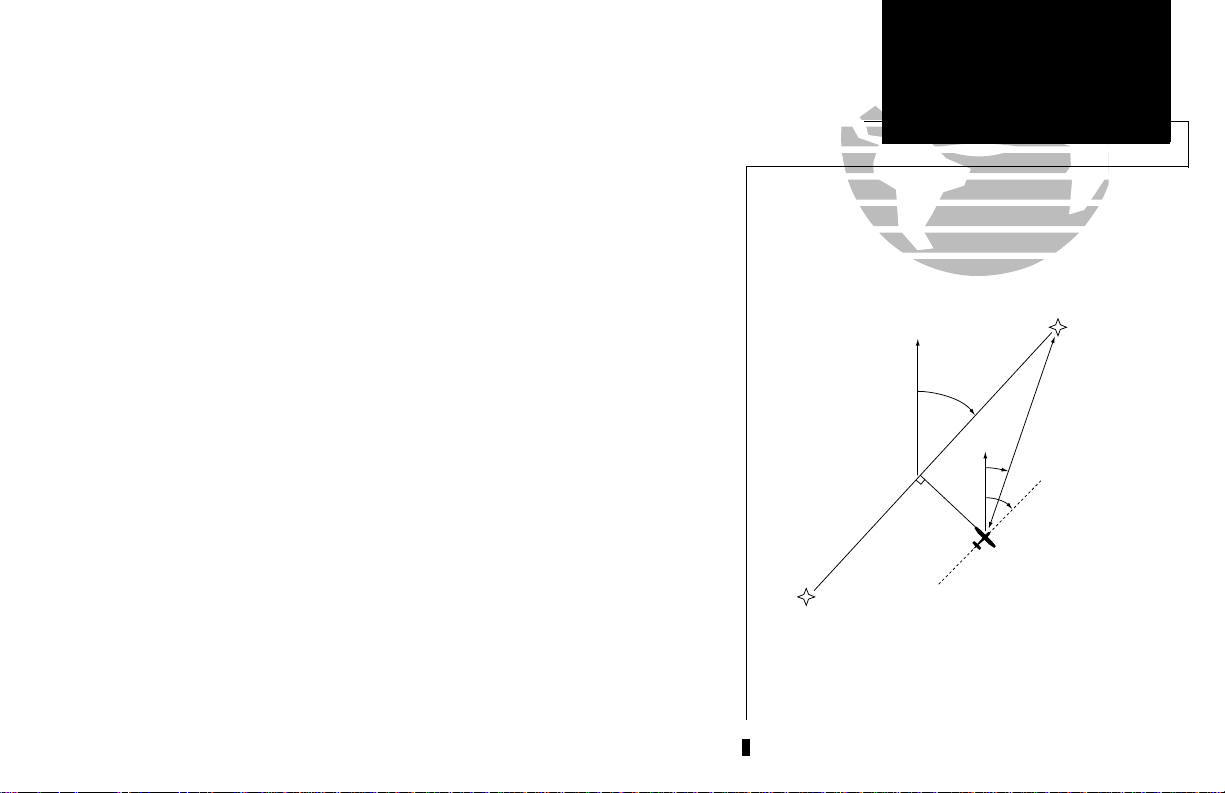
WPT 1
S
T
R
L
NORTH
NORTH
WPT 2
BRG
TRK
G
S
DIS
A
IR
P
L
A
N
E
D
T
K
The following functions may be displayed in the ground speed field:
• gs— Your present speed over the ground.
• str— Steer direction and distance, or digital crosstrack error. An ‘L’ or ‘R’
indicates which direction to steer, while the distance value indicates how far you are off course.
The following functions may be displayed in the distance field:
• dis— Distance from present position to the ‘active to’ waypoint.
• str— Steer direction and distance, or digital crosstrack error. An ‘L’ or ‘R’
indicates which direction to steer, while the distance value indicates how far you are off course.
The following steering functions may be displayed in the track field:
• trk— Track, the direction of movement relative to the ground.
• brg— Bearing, the direction from your present position to the waypoint.
• cts— Course to steer to reduce cross track error and re-intercept the dtk.
• dtk— Desired track, the course between the active from and to waypoints.
• trn— Turn, the direction and degrees to turn to get back on course.
The following information can be displayed in the ete field:
• eta— Estimated Time of Arrival (at the active to waypoint).
• ete— Estimated Time Enroute (to the active to waypoint).
• trk— Track, or the direction of movement relative to the ground.
• vn— Vertical Navigation, or VNAV. If VNAV has been activated, this field
indicates either the elapsed time before the VNAV maneuver is to
begin or the VNAV altitude (the suggested altitude you should be flying in order to complete the maneuver).
REFERENCE
NAV KEY
Proximity Field
Configuring the
CDI Page
SECTION
1
11
Page 22
12
SECTION
1
The NAVCOM page lists the frequencies for your
departure (or nearest) and destination airports in
the following order:
Departure Arrival
• ATIS • ATIS
• Clearance Delivery • Approach
• Clearance Pretaxi • Arrival
• Ground • Class B
• Tower • TMA
• Other • CTA
• Multicom • Class C
• Unicom • TRSA
• Departure • Tower
• Class B • Other
• TMA • Multicom
• CTA • Ground
• Class C • Unicom
• TRSA
REFERENCE
NAV KEY
Waypoint
CDI &
NAVCOM Pages
Communication
To change any of the selectable fields on the CDI page:
1. Press Ctwice to activate the cursor in the GPS window.
2. Rotate Oto highlight the field you would like to change.
3. Rotate Kto change the field to display the desired information.
4. Rotate Oto highlight another field, or Cto finish.
The next page available from the GNC 300’s NAV key is the navigation communications (NAVCOM) page. The NAVCOM page provides a list of the airport
frequencies at your departure and arrival airports, allowing convenient selection of
every frequency you’ll need along your flight path. To scroll through the list of frequencies, rotate the inner knob (K) in the direction of the arrow prompts at the
bottom left of the page.
The frequencies displayed for the departure and arrival airports are listed in the
order you are most likely to use them (see left), with the available frequencies displayed to the right of the airport identifier. If you do not have an active direct-to or
route, the NAVCOM page will display the frequencies for the airport nearest your
present position.
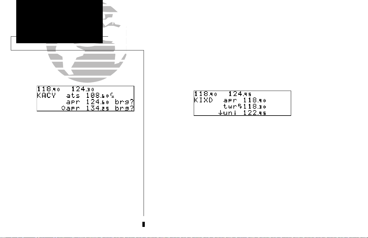
Page 23
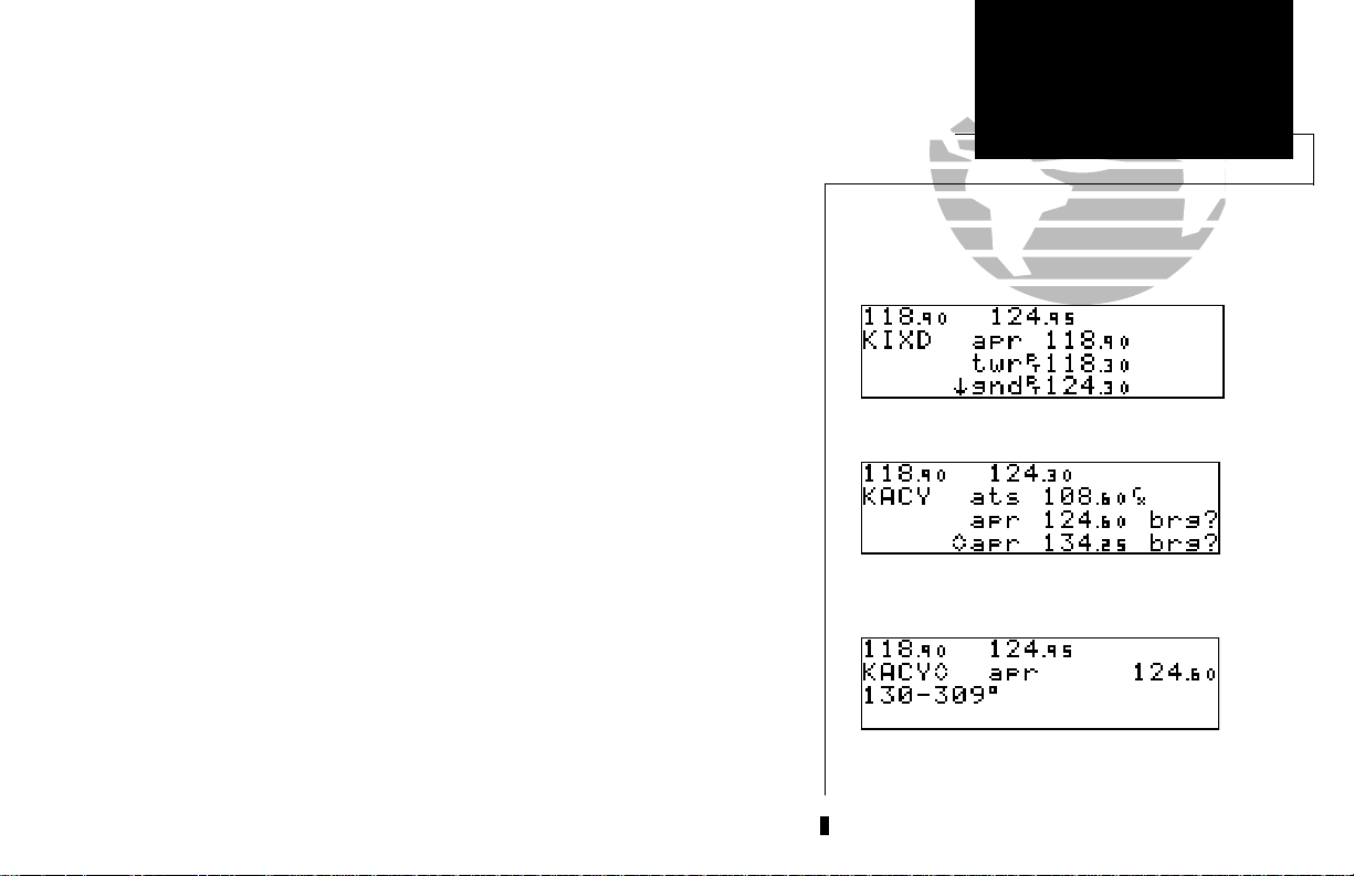
If a frequency has sector or altitude restrictions, the frequency will be followed by
a ‘brg?’.
To view restrictions on a frequency:
1. Press Ctwice to activate the cursor in the GPS window.
2. Rotate Oto highlight the ‘brg?’ next to the frequency you wish to view.
E
3. Press
Once you begin viewing restrictions, you can view any additional frequencies with
restrictions by rotating K. You can also view the waypoint information pages by
rotating O. Information contained on these pages is covered in Section 3. To return
to the NAVCOM page, press N.
Some frequencies in the NAVCOM page are followed by tags which designate their
usage:
‘tx’ – transmit only ‘rx’ – receive only
‘pt’ – part time frequency
To make any of the frequencies on the NAVCOM page the standby frequency:
1. Press Ctwice to activate the cursor in the GPS window.
2. Rotate
3. Press
automatically advance to the next frequency on the list.
to begin viewing restrictions.
O
until the desired frequency is highlighted.
E
to transfer the highlighted frequency to the standby frequency. The cursor will
REFERENCE
NAV KEY
Waypoint
NAVCOM Page
Communication
NAVCOM Page
NAVCOM page with receive only (rx) frequencies
and frequencies with restrictions (brg).
SECTION
1
An arrow prompt is displayed on the bottom line of the display to indicate addi-
tional frequencies available on the list.
Frequency restrictions on 124.60.
13
Page 24
SECTION
1
REFERENCE
NAV KEY
CDI Page
Position Page
The GNC 300 position page displays your present latitude and longitude,
altitude and a reference waypoint field; and is also used to enter the altimeter setting
during approach operations. The altitude and reference waypoint fields are selectable
to configure the page to your own preferences and current navigation needs.
Altimeter Setting
(during approach navigation)
Altitude, MSA or ESA
Position (lat/lon)
Position page displaying MSA.
The altitude field can display either the present altitude, minimum safe altitude
(MSA) or enroute safe altitude (ESA). MSA is the recommended minimum altitude
within a ten mile radius of your present position. ESA is the recommended minimum
altitude within a ten mile radius of your course on an active route or direct-to. MSA
and ESA altitudes are calculated from information contained in the database and gen-
The same position page displaying ESA. MSA and
ESA are computed based on data stored in the
NavData card. This information cannot be solely
relied upon as an absolute measure of safe altitude
in your area, particularly if the data card is out of
date. Consult current charts and NOTAMS for
more complete information.
14
erally include mountains, buildings and other permanent features (see left).
To change the altitude field:
1. Press Ctwice to obtain a flashing cursor in the GPS window.
2. Rotate Ountil the ‘alt/ESA/MSA’ field is highlighted.
3. Rotate Kto display the desired data. Press Cto return to normal navigation.
Proximity Field
Page 25
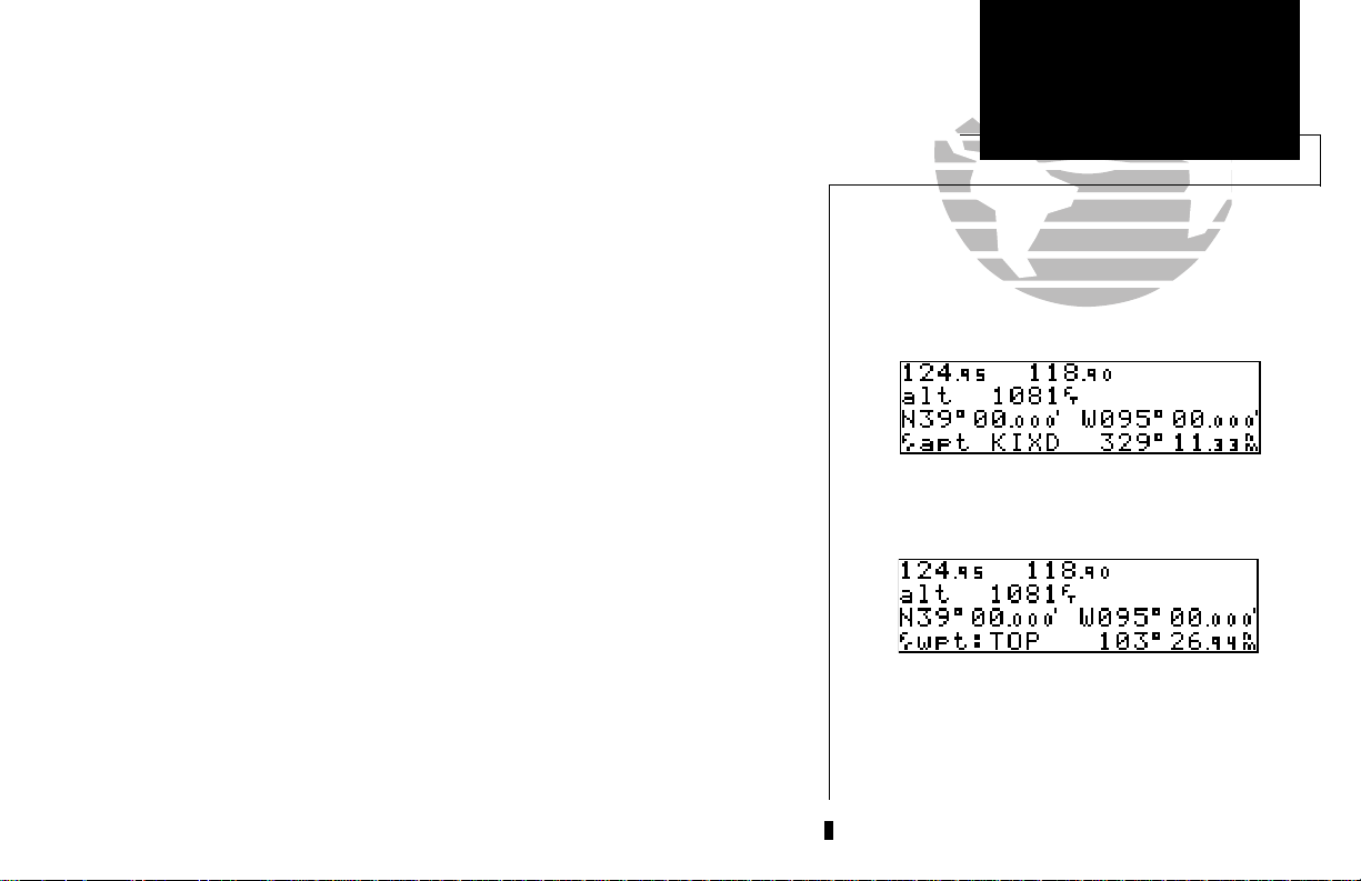
The position page also features a reference waypoint field, located at the bottom
of the page, to indicate your bearing and distance from a selected waypoint. The reference waypoint field can display the following:
• Range, bearing and identifier from the nearest airport, VOR, NDB,
intersection, or user waypoint
• Range, bearing, and identifier from a user specified waypoint
The default setting is to display the nearest airport.
To change the reference waypoint field to display the nearest airport, VOR, NDB,
intersection, user waypoint or the range and bearing from a user selected waypoint:
1. Press Ctwice to activate the cursor in the GPS window.
2. Rotate Oto highlight the proximity field after the fr.
3. Use Kto choose which waypoint type you would like displayed. (Choose ‘wpt’ if you
would like a specific waypoint range and bearing to be displayed.)
4. Press Cto remove the cursor, or:
If you have selected ‘wpt’:
5. Rotate Oto advance the cursor to highlight the identifier field.
REFERENCE
NAV KEY
Changing Fields
Reference
on the CDI Page
Waypoint Field
Position page displaying the nearest airport
(KIXD) as the reference waypoint.
SECTION
1
6. Use the
7. Press Cto finish.
This allows any waypoint’s distance and bearing to be listed continuously on the
position page, and is especially useful when trying to locate your position on a
sectional or when an approach reference is not the closest navaid.
K
and Oknobs to enter the identifier name. (This waypoint identifier can be
an airport, VOR, NDB, intersection, or user waypoint.) Press
E.
Position page displaying the TOP VOR as the reference waypoint. This configuration can be used to
help monitor your distance and radial to a waypoint or DME arc reference (see Section 6).
Note the waypoint category is listed as ‘wpt’ rather
than ‘VOR’ because the GNC 300 is not using the
nearest VOR for the reference waypoint.
15
Page 26
SECTION
1
REFERENCE
NAV KEY
NAV Menu 1 & Trip
Satellite Status Page
Planning
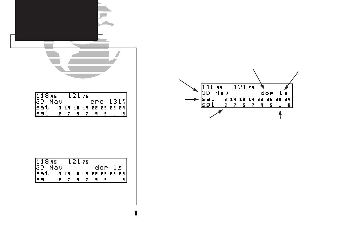
The GNC 300’s satellite status page provides satellite information to monitor
GPS coverage and receiver performance. This is helpful when you may be experiencing low signal levels due to poor coverage or installation problems.
To view the satellite status page:
1. Press Nand rotate Ountil the satellite status page appears.
EPE/DOP
Receiver Status
Satellites in view
Status page with EPE displayed.
The top line of the status page displays the receiver status and the current DOP or
EPE. Dilution of precision (DOP) is a measure of the satellite geometry quality and
relative accuracy of your position, with 1 meaning good geometry and 10 meaning
poor. Estimated position error (EPE) is an overall measure of your positional accuracy
in feet or meters using signal and data quality, receiver tracking status and DOP.
To view information on DOP/EPE:
Status page with DOP displayed.
16
Signal strength of
satellite being tracked (1-9)
1. PressNand rotate Oto display the satellite status page.
2. If the desired field (EPE or DOP) is not displayed, press
K
3. Use
to change between ‘epe’ and ‘dop’. Press Cto finish.
Satellite in view
but not receiving signal
C
twice.
EPE/DOP
value
Page 27
The receiver status field, located at the top left of the page, can display the fol-
lowing messages under various conditions:
Search sky - The GNC 300 is searching the sky for visible satellites. You
will be informed with the message ‘Searching the Sky’.
Acquiring - The GNC 300 is acquiring satellites for navigation.
2D Nav - The GNC 300 is in 2D navigation mode. If your installation
does not include an altitude serializer, you must enter the
altitude manually (see page 2).
3D Nav - The GNC 300 is in 3D navigation mode and will compute
altitude.
Simulator - The GNC 300 is in simulator mode, which should only be
used for practice and trip planning. Never use simulator
mode for actual navigation.
Poor cvrg - The GNC 300 can’t acquire sufficient satellites for navigation.
Need alt - The GNC 300 needs altitude in order to start/continue navi-
gation. Select the position page and enter the altitude.
Need pres - The GNC 300 needs the current altimeter (barometric pres-
sure) setting at the approach airport. Enter the altimeter setting on the position page.
REFERENCE
NAV KEY
Density Altitude/
Receiver Status Field
True Air Speed
Acquiring satellites for navigation.
SECTION
1
Not usable - The GNC 300 is unusable due to incorrect initialization or
abnormal satellite conditions. Turn the unit off and on again.
If this does not help, return the unit to an authorized
GARMIN dealer for service.
Searching the Sky.
17
Page 28
SECTION
1
REFERENCE
NAV KEY
Fuel Planning
Satellite Data Page
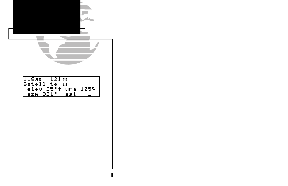
The second and third lines of the satellite status page provide the satellite number
and signal strength of each satellite in view. Additional information regarding each
satellite’s azimuth, elevation and other data is also available.
To view individual satellite information:
1. Press Nand use Oto display the satellite status page.
2. Press Ctwice to activate the cursor in the GPS window.
3. Use Oto highlight the satellite number you wish to view and press E.
This will display the satellite data page, showing the selected satellite’s number,
elevation angle, rise or fall indication, user range accuracy (URA, or the range
measurement accuracy as determined by the satellite), azimuth and signal strength.
To view other satellites:
Viewing individual satellite information.
18
4. Rotate Kto view information for the next satellite.
5. Rotate Oto return to the satellite status page and press Con the satellite status
page when you are finished.
Page 29
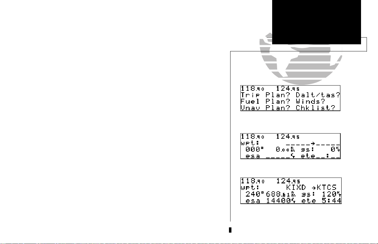
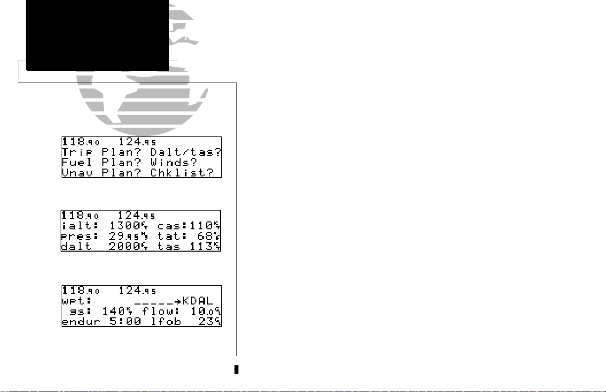
In addition to the other four pages, the GNC 300 features two menu pages to per-
form a host of planning and navigation functions. NAV Menu 1 provides access to
the following functions:
• Trip Planning • Density altitude/true air speed calc.
• Fuel Planning • Winds aloft calculations
• VNAV Planning • Checklists
To display NAV Menu 1:
1. Press N.
2. Rotate Ountil NAV Menu 1 is displayed.
Trip Plan is the first function listed on NAV Menu 1 and allows the pilot to view
distance, ESA, bearing and estimated time enroute (ETE) between any two waypoints,
and for programmed route legs. The ground speed can be varied manually to calculate several possible ETEs.
To use the trip planning function:
1. Press Nand rotate Ountil NAV Menu 1 is displayed.
2. Press Ctwice, then Eto access trip planning.
REFERENCE
NAV KEY
Winds Aloft &
NAV Menu 1
VNAV
Trip Planning
Calculations
NAV Menu 1
SECTION
1
3. Rotate Kto select waypoint mode or desired route number, and press E.
4. For direct-to navigation, use
E
to accept the waypoints. To use your present position as a waypoint, leave the way-
point field blank.
5. For route calculations, choose either ‘cum’ for cumulative data (from beginning to end) or
the leg desired by rotating
6. Use
K
and Oto enter the ground speed. Press Eto calculate the values and
to finish.
K
and Oto enter the ‘to’ and ‘from’ waypoints. Press
K
.
C
Trip Planning Page
Trip planning with values calculated.
19
Page 30
SECTION
1
REFERENCE
NAV KEY
VNAV & Checklists
Density Altitude &
True Airspeed
Nav Menu 1
The density altitude/true airspeed function is also accessed from NAV Menu 1.
Density altitude is the altitude at which your aircraft will perform depending on several
environmental conditions, including air pressure and total air temperature (the temperature including the effect of speed, read on a standard outside temperature gauge on most
aircraft). True airspeed considers the same factors.
To calculate the density altitude and true air speed:
1. Press Nand rotate Ountil NAV Menu 1 is displayed.
2. Press Ctwice and rotate Oto highlight ‘Dalt/tas?’.
3. Press Eto access the density altitude page.
4. Use Kand Oto enter the indicated altitude and press E.
5. Use Kand Oto enter the calibrated air speed (cas). Press E.
6. Use Kand Oto enter the air pressure (‘pres’) and press E.
7. Use Kand Oto enter the total air temperature.
8. Press Eand the density altitude and true air speed will be calculated and displayed.
Density Altitude/True Airspeed Page
required on the density altitude page, they will be used as the defaults.
tion and programmed routes. The fuel planning function requires the pilot to know
Fuel Planning Page
20
the initial amount of fuel on board and the flow rate. You may also enter different
ground speeds to view various information based on different travel times. If your
installation is interfaced to a fuel flow sensor, the flow rate and other information will
be used from the fuel flow sensor.
9. Press Cto remove the cursor.
If your installation includes components to provide any of the information
The fuel planning page will display fuel requirements for both direct-to naviga-
Page 31

To perform fuel planning operations:
1. Press Nand rotate Ountil NAV Menu 1 is displayed.
2. Press Ctwice and rotate Ountil ‘Fuel Plan?’ is highlighted. Press E.
3. Rotate Kto select either ‘wpt’ for direct navigation or the desired route number. Press E.
4. For waypoint-waypoint navigation, use Kand Oto enter the ‘to’ and ‘from’ waypoints.
Press
E
to accept the waypoints. To use the present position as a waypoint, leave the
corresponding waypoint field blank.
5. For route calculations, choose either ‘cum’ for cumulative route fuel requirements
(from beginning to end) or the leg desired by rotating
If leg is selected, it displays the amount of fuel required to fly until that leg is complete.
For example: The fuel required to complete leg 2 is leg 1 + leg 2.
Fuel required to complete leg 4 is leg 1 + leg 2 + leg 3 + leg 4.
6. Rotate Oto advance the cursor to ‘fob:’ or ‘gs:’ (depending on which is displayed).
7. Use Kand Oto enter the fuel on board or the ground speed. Press E.
8. Rotate Oback two positions to highlight the ‘fob:’ or ‘gs:’ field again.
9. Rotate Kto display the other information. Press E.
10. Use Kand Oto enter the remaining data. Press E.
K
K
.
REFERENCE
NAV KEY
Checklists, NAV
NAV Menu 1
Fuel Planning
Menu 2 &
Fuel Planning Page
SECTION
1
11. Use Kand Oto enter the flow rate, in units per hour, if needed. Press E.
The GNC 300 will calculate the range and endurance (how long the fuel will last)
of your aircraft. These are found in the first field on the bottom row of the page. The
fuel left on board (lfob) and reserve after the selected direct-to, leg or route will also
be displayed in the second field on the bottom row.
Fuel planning page with other information.
21
Page 32

SECTION
1
REFERENCE
NAV KEY
Winds Aloft &
Date & Time,
VNAV Functions
Trip Timer
NAV Menu 1
Winds Aloft Page
The GNC 300’s winds aloft function is used to calculate the true direction and
speed of the winds aloft, and indicates whether you are flying with a head wind or
tail wind, and the wind speed.
To calculate winds aloft:
1. Press Nand rotate Ountil NAV Menu 1 is displayed.
2. Press Ctwice and rotate Ountil ‘Winds?’ is highlighted. Press E.
3. Use Kand Oto enter your present heading in the ‘hdg:’ field. If your installation
includes a fuel/air data computer, this will be displayed automatically. Press
4. Use Kand Oto enter your true airspeed (TAS) in the ‘tas:’ field. If you have previously
calculated it using the density altitude/true air speed function, it will be displayed as the
default. Press
The VNAV function calculates vertical speed requirements to reach a desired altitude
before or after a specified distance from a waypoint. This is helpful when you’d like to descend
to a certain altitude near an airport or climb to an altitude before reaching a waypoint.
To calculate vertical navigation parameters:
1. Press
2. Press
3. Use Kand Oto enter the initial (from) altitude. Your GPS altitude will be displayed
as the default. Press
E
. The wind direction and speed and head/tail wind will be displayed.
N
and rotate Ountil NAV Menu 1 is displayed.
C
twice and rotate Ountil ‘Vnav Plan?’ is highlighted. Press
E
.
E.
E
.
4. Use Kand Oto enter the desired final (to) altitude. Press E.
Vertical Navigation Page
22
5. Use Kand Oto enter the distance from the waypoint. Press E.
6. Use Kto select ‘before’ or ‘after’ the waypoint. Press E.
7. Use Kand Oto select the waypoint identifier. If you are on a route or a direct-to,
the ‘active to’ identifier will be displayed automatically. Press
E
.
Page 33

You will now notice that the vertical speed field has been calculated, based on
your present speed. If you desire a more rapid climb or descent:
8. Use Kand Oto enter the new desired vertical speed, or press E to accept the
calculated value.
9. Press
E
to activate the vertical navigation function.
If you enter a greater value, the GNC 300 will display the elapsed time before the
maneuver is to begin. When the countdown reaches 15 seconds, you will be informed with
the message ‘Start altitude chng’. The VNAV function will automatically be cancelled if the
active direct-to or route is changed in any way, and you will be informed with a ‘VNAV
cancelled’ message.
The GNC 300 will allow you to create up to nine checklists with 30 items each to
remind you of repetitive tasks that can be called up at any time for review. The checklist
feature is useful for creating pre-flight checklists, landing checklists, emergency procedures, etc. Each name or function can have up to 16 characters each.
To create a checklist:
N
1. Press
2. Press
3. Press
Press
4. Use
and rotate Ountil NAV Menu 1 is displayed.
C
twice and rotate Ountil ‘Chklist?’ is highlighted. Press E.
C
and use Oto highlight the checklist number you would like to create or edit.
E
.
K
and Oto enter the title of the checklist. Press
E.
REFERENCE
NAV KEY
GPS Planning
NAV Menu 1
VNAV & Checklists
VNAV after a new descent rate has been entered.
VNAV displayed on CDI page.
SECTION
1
This will display the checklist items page. On this page, you can enter each task,
such as ‘Check Fuel’.
5. Use Kand Oto enter the checklist item. Press E.
C
6. You may repeat step 5 to enter additional items, or press
to finish.
Checklist Catalog Page
23
Page 34

SECTION
1
REFERENCE
NAV KEY
Scheduler,
Checklists
Sunrise & Sunset
NAV Menu 2
To execute a checklist:
1. Press Nand rotate Ountil NAV Menu 1 is displayed.
C
2. Press
3. Scroll through available checklists using
4. Press
5. Press
To delete a checklist item or an entire checklist:
twice and rotate Ountil ‘Chklist?’ is highlighted. Press E.
K
.
C
and use Oto highlight the checklist you would like to see. Press E.
E
to check off list items.
1. To delete a checklist item, highlight the desired item and press
2. To delete an entire checklist, highlight the desired list and press \, followed by E.
Executing a checklist.
NAV Menu 2
Approach Timer
24
The GNC 300’s NAV Menu 2 provides access to various timer and planning func-
tions, including:
• Approach timer • Clock (Date and time)
• Trip Timer • RAIM Prediction
• Scheduler • Sunrise and sunset calculations
The approach timer acts as either a count up or a count down timer that can be
set or reset at any time.
To activate/change/view the approach timer:
N
1. Press
2. Press
3. Rotate
4. Use
5. Rotate
and rotate Ountil NAV Menu 2 is displayed.
C
twice and rotate Ountil ‘Appr Time?’ is highlighted. Press E.
K
to select either ‘Count up’ or ‘Count down’. Press E.
K
and Oto set the time to begin counting from. Press E.
O
to select the desired function: ‘Start’, ‘Stop’, or ‘Reset’. Press Eto execute.
\
, followed by E.
Page 35

When the count down timer reaches zero, you will be informed with a ‘Timer
expired’ message. The timer will then begin to count up, keeping track of how long it
has been since it expired. The timers run, if not altered, anytime the GNC 300 is on.
The GNC 300 clock function keeps track of both UTC time (Greenwich Mean
Time or Zulu Time calculated from the satellites) and local time, and allows you to
designate which format is used for ETA calculations. The local time and date can be
set without doing a UTC to local time conversion.
To set the local date/time:
1. Press Nand rotate Ountil NAV Menu 2 is displayed.
2. Press Ctwice and rotate Ountil ‘Clock?’ is highlighted. Press E.
K
3. Use
4. Use
5. Use Kand Oto set the local time. Press E.
6. Press Cto complete.
The GNC 300’s trip timer will automatically keep track of the duration of your
current trip and can be configured to run when the GNC 300 is on, or when your
ground speed exceeds a specified value (see Section 7).
To view or reset the trip timer:
to select either ‘UTC’ or ’local’ time to be displayed in the time fields. Press E.
K
and Oto set the local date. Press E.
REFERENCE
NAV KEY
Comm Features
NAV Menu 2
Clock & Trip Timer
Timer expired message.
Entering a local time.
SECTION
1
1. Press Nand rotate Ountil NAV Menu 2 is displayed.
2. Press
C
twice and rotate Ountil ‘Trip time?’ is highlighted. Press E. The current
time of day, departure time, and time enroute will be displayed.
3. To reset the timer, press
E
. To skip resetting the timer, press C.
Resetting the trip timer.
25
Page 36

SECTION
1
REFERENCE
NAV KEY
Comm Features
NAV Menu 2
RAIM Prediction
Enter the time and date for RAIM prediction.
Confirm the selected waypoint.
The RAIM Prediction function allows you to confirm that GPS coverage is
available for a specific location or waypoint any day of the year. Receiver
Autonomous Integrity Monitoring performs checks to ensure that the GNC 300 will
have adequate satellite geometry to work with during your flight. RAIM availability
will be near 100% in Oceanic, En route, and Terminal phases of flight. Because the
FAA’s TSO requirements for non-precision approaches specify significantly better
satellite coverage than other flight phases, RAIM may not be available when flying
some approaches. The GNC 300 will automatically monitor RAIM during approach
operations and warn you if RAIM is not available. RAIM prediction will help you plan
for a pending flight to confirm that the GNC 300 can be used for an approach, and
should be calculated the night before or the day of the desired flight.
To predict RAIM availability:
C
1. Press
2. Rotate Oto highlight the field which you would like to change.
3. Use
position. Press
Use
date will be displayed automatically. Press
4. Rotate Oto highlight ‘Compute RAIM?’.
twice and rotate Oto highlight ‘RAIM prd?’. Press E.
K
and Oto enter the waypoint name, or leave it blank to use your current
E
to accept. OR:
K
and Oto enter the day, month and year of the information desired. Current
E
to accept.
5. Press Eto compute information.
When the computations are complete, the GNC 300 will display whether or not
RAIM available for the entered time and date.
26
RAIM is available for the specified waypoint at the specified date and time.
Page 37

The scheduler function will display reminder messages after a certain elapsed time such
as Change oil, Switch fuel tanks, Overhaul, etc. For example, if you enter ‘Change Oil’ to be
displayed in 30 hours, the message ‘Change Oil’ will be displayed after the GNC 300 has
been on in Normal operating mode for 30 hours. After appearing, the message will be displayed each time the GNC 300 is turned on until it is changed or deleted.
Entering a scheduled message.
To enter a scheduled message:
1. Press Nand rotate Oto display NAV Menu 2.
2. Press Ctwice and rotate Ountil ‘Scheduler?’ is highlighted. Press E.
3. Rotate Kto display the message you would like to edit. Press Cand rotate Oto
highlight the message you would like to edit. To delete, press
4. Use Kand Oto enter the message. Press E.
5. Use Kand Oto set the elapsed time until the message is displayed, in hours and
minutes, up to 99 hours and 59 minutes (this time is cumulative and counts whenever
the GNC 300 is on in normal operating mode). Press
You may edit another by repeating steps 3, 4 and 5, or if you are finished, press C.
E
.
\
, then E.
REFERENCE
NAV KEY
WPT Key Overview
NAV Menu 2
Scheduler
The scrolling arrow prompt indicates which direction to scroll to view additional listings.
The scheduled message will appear after the timer
expires and after the GNC 300 is powered up
until the message is changed.
SECTION
1
27
Page 38

SECTION
1
NAV KEY
Sunrise/Sunset
Calculations
Sunrise/Sunset Planning Page
The GNC 300 sunrise/sunset planner allows you to calculate the sunrise and sun-
set times for a specified date for your present position or any waypoint.
To calculate sunrise and sunset times at a waypoint or at your present location:
1. Press Nand rotate Ountil NAV Menu 2 is displayed.
2. Press Ctwice and rotate Oto highlight ‘Sunrise?’. Press E.
3. Use Kand Oto enter the waypoint identifier, or leave blank to use current position.
Press
E
.
4. Press Eto accept the waypoint information.
5. Use Kand Oto enter the date desired.
6. Press Eand the sunrise and sunset times will be calculated and displayed.
28
Page 39

Section 2
Communicating with the GNC 300
The GNC 300 features a digital VHF radio that provides a seamless transition from
communication to navigation, bringing the two most important functions in flying
together in one panel-mount unit. The GNC 300 operates in the aviation voice band,
from 118 to 136.975 MHz, in 25 kHz steps.
Communication frequencies are selected by activating the cursor in the standby
frequency field and using the inner and outer knobs to dial in the desired frequency.
A frequency may also be quickly selected from the navigation database by simply
highlighting the frequency and pressing the Ekey. Once a desired frequency is displayed in the standby field, it may be made the active frequency by pressing the
key. Note that the active frequency may not by accessed directly. Whenever the cursor is
active in the comm window, the standby frequency will be highlighted (e.g.,
‘<121.5>’).
To access the standby frequency, press C.
This allows you to change the megahertz (number to the left of the decimal) by
rotating Oand the kilohertz (number to the right of the decimal) by rotating K. If
you would like to keep the standby field ‘hot’ (ready for an immediate frequency
change), leave the cursor active in the comm window. To remove the cursor, press
C
twice after you have selected the desired frequency.
@
REFERENCE
COMM FEATURES
Waypoint
Overview
Information
CDI page with cursor inactive.
CDI page with standby field active.
SECTION
2
To make the standby frequency the active frequency, press @.
The frequencies will be flip-flopped and you’ll be able to transmit and receive on
the standby frequency previously entered. This can be done at any time, regardless of
cursor or GPS status.
To flip-flop the frequencies, press @.
29
Page 40

SECTION
2
To auto-tune from the nearest airport page, press
ENT.
To select a frequency from a list, highlight the
desired frequency and press ENT.
REFERENCE
COMM FEATURES
Entering Waypoints
Overview/
Auto-Tuning
During the course of navigating with the GNC 300, there may be times when you
need to quickly select a comm frequency while you are in the middle of entering data
in the GPS window. Whenever data entry in the GPS window is interrupted by activating the standby frequency field, the GPS field in use will become ‘splatted’, or
blocked out.
Once the standby frequency has been entered, you may return to data entry by
pressing the Ckey. The flashing cursor will return you to the active GPS field at
the point where you stopped data entry.
The GNC 300’s auto-tune feature allows you to quickly select any database frequency in the GPS window as your standby frequency.
To auto-tune a single frequency displayed in the GPS window:
1. Press Ewith the cursor inactive.
2. To make the standby frequency the active frequency, press @.
To auto-tune a frequency from a list displayed in the GPS window:
1. Press
C
twice to activate the cursor in the GPS window.
2. Rotate Oto highlight the desired frequency.
3. Press Eto make the selected frequency the standby frequency.
Another useful feature integrating the GNC 300’s navigation and communication
capabilities is the Navigation Communications (NAVCOM) page, which is
30
accessed using the Nkey. See pages 12-13 for more on the NAVCOM page.
Page 41

The GNC 300’s automatic squelch and volume controls are located at the bot-
tom left of the unit, near the NavData card slot.
To adjust the radio volume:
1. Rotate the Bknob.
Whenever the GNC 300 is powered up, the automatic squelch will be in the ‘on’
position, allowing only transmissions which are powerful enough for clear broadcast
to be received. Manual squelch control is not available.
To override the automatic squelch control:
1. Press the Qkey. Press Qagain to return to automatic squelch.
Whenever the GNC 300 is transmitting, a ‘tx’ icon will appear between the active
and standby frequency fields. If the microphone is stuck or accidentally left in the
keyed position, or if the headsets continue to transmit after the key is released, the
radio will timeout after 35 seconds of continuous broadcasting. You’ll also receive a
‘Stuck mic/Tx disabled’ message as long as the stuck condition exists.
The GNC 300’s emergency channel select feature provides a quick method of
selecting the 121.5 MHz frequency as the active frequency in the event of an in-flight
emergency. The emergency channel select is available whenever the unit is on, regardless of GPS or cursor status, or loss of the display.
To automatically tune for emergency transmission:
REFERENCE
COMM FEATURES
Airport
Squelch & Volume/
Emergency Channel
Information
‘TX’ indicating radio transmission.
The emergency channel will appear in the active
field.
SECTION
2
1. Press and hold the @key for more than two seconds.
31
Page 42

32
SECTION
WPT KEY
3
Please note that your GNC 300 uses ICAO identifiers
for all airports. All U.S. airport identifiers which contain
only letters use the prefix ‘K’. For example, Los Angeles
International is KLAX under the ICAO standard. Other
airports, such as Otten Memorial (3VS), that contain
numbers in the identifier, do not require the ‘K’ prefix.
Many foreign countries use two letter prefixes. For more
information on ICAO identifiers, contact:
Overview
Document Sales Unit
International Civil Aviation Organization
1000 Sherbrooke, Suite 400
Montreal, Quebec
Canada H3A 2R2
Section 3
Waypoint and Database Information
The GNC 300 uses a Jeppesen NavData® card to provide position and facility
information for thousands of airports, VORs, NDBs and intersections. Each facility in
the database is stored as a waypoint with its own latitude/longitude, identifier (up to
five letters and/or numbers), and other pertinent information. Up to 1,000 user waypoints may also be created and stored in the GNC 300’s internal memory.
Waypoint Menu Page
Waypoint Comments List
Waypoint information is available through four primary waypoint pages accessible
from the GNC 300’s WPT key. The waypoint pages may be scrolled through by pressing the WPT key and rotating the outer knob until the desired page is displayed, or
by pressing the WPT key repeatedly.
Proximity Waypoints Page
User Waypoint List
Page 43

The GNC 300 organizes waypoints into one of five waypoint categories for your convenience. Each waypoint category provides different types of detailed information for a
selected facility:
• Airports - Identifier, city/state, country, facility name, position (lat/lon),
elevation, fuel services and communications frequencies.
• VORs - Identifier, city/state, country, facility name, position (lat/lon),
frequency, magnetic variation, co-located DME or TACAN and weather
broadcast indication.
• NDBs - Identifier, city/state, country, facility name, position (lat/lon),
frequency and weather broadcast indication.
REFERENCE
WPT KEY
Waypoint Categories
Airport
& Menu Page
Communication
SECTION
3
• Intersections - Identifier, country, position (lat/lon), nearest VOR.
• User - Identifier (name), position (lat/lon), reference waypoint.
To view the waypoint information for a desired waypoint, select the waypoint
category from the waypoint menu page.
To choose a waypoint category (for viewing information):
W
1. Press
2. Press Ctwice and rotate Oto highlight the desired waypoint category.
3. Press
the selected category will appear with the waypoint identifier field ready for entry.
and rotate Oto display the waypoint menu page.
E
to accept the waypoint category. The waypoint identification or position page for
Waypoint Menu Page
Airport Position Page
VOR Position Page
33
Page 44

SECTION
3
REFERENCE
WPT KEY
Airport Runway
Entering Waypoints
Information
After a waypoint category is selected, information for a waypoint may be viewed
by entering the identifier or name of the desired waypoint. Airports, VORs, and
NDBs may be entered by either the identifier, name, or the location (city) of the facility. Intersections and user waypoints must be entered by the identifier.
To enter a waypoint identifier:
1. With the flashing cursor over the waypoint field, use
waypoint identifier.
As the identifier is entered, the GNC 300’s Spell’N’Find feature will scroll through
the available database, displaying any waypoints with the same identifier letters you
have entered to that point. When the desired waypoint is displayed, press Cto
remove the cursor.
To obtain waypoint information by entering the facility name of the
airport, the name of the VOR or NDB, or its location:
Entering a waypoint by identifier.
Entering a waypoint by city. Note that punctuation marks are not used when entering locations
or names. Use spaces, where appropriate, to identify these marks. For example, St. Louis would be
entered as “ST LOUIS” without a period.
34
that match the letters you have entered. If duplicate entries exist for the entered identifier, name or location, additional entries may be viewed by rotating K. Once the
desired waypoint is displayed, press Cto continue.
1. Press Wand rotate Oto display the waypoint menu page.
2. Press Ctwice and rotate Oto highlight the desired waypoint category.
3. Press Eto accept the waypoint category.
4. Rotate Oto highlight the middle field to enter location (city) OR
Rotate Oto highlight the bottom field to enter facility name or VOR/NDB name.
5. Use Kand Oto enter the location or the name, and press Cto finish.
As the information is entered, the GNC 300 will display any entries in its database
K
and Oto enter the
:
Page 45

Once a waypoint category and identifier have been selected, the GNC 300 will
provide extensive information through a set of waypoint pages for the selected category. We’ll now go through the pages available for each waypoint category in the order
they appear on the waypoint menu page: airports, VORs, NDBs, intersections and
user waypoints.
Airport Information
Airport Identification Page
REFERENCE
WPT KEY
VOR Information
Airport Information
SECTION
3
Airport Comments Page
Airport Runway Page
Airport
Communication Page
To scroll through the airport pages:
1. Make sure the cursor is not flashing. If it is, press C.
2. Rotate Oin either direction to scroll through the available pages.
Airport Position Page
Airport Procedures Page
35
Page 46

SECTION
3
REFERENCE
WPT KEY
VOR Position Page
Airport Pages
Airport Position Page
The GNC 300 features six airport pages:
airport identification— allows entry of desired airport by identifier,
facility name or city; displays region and/or country of facility.
airport position— allows entry of desired airport by identifier; displays
latitude, longitude and elevation; indicates usage and fuel availability;
displays approach availability and airport control/radar capability.
airport procedures— allows entry of desired airport by identifier; displays all available approaches, SIDs and STARs for the selected airport.
airport communication— allows entry of desired airport by identifier;
displays radio frequencies/usage, and sector and altitude restrictions.
airport runway— allows entry of desired airport by identifier; indicates
runway designations, length, surface and lighting information; displays
ILS/localizer and/or pilot-controlled lighting frequencies.
airport comments— allows entry of desired airport by identifier; displays
user comments for the selected airport.
Waypoint Type
and Identifier
Airport Communication Page
Airport Runway Page
36
Location
(city/state)
The airport identification page displays a selected airport’s identifier, region
and country, city/state and facility name. The identification page is always the first
airport page available, allowing you to quickly review an airport facility or select
another facility by entering the identifier, facility name or city of the desired airport.
Region/Country
Facility
Name
Page 47

The airport position page displays the latitude, longitude and elevation of the
selected airport, as well as usage or fuel availability, available approaches and airport
control/radar capability. The following descriptions and abbreviations are used on the
airport position page:
Elevation— In feet or meters
Usage/Fuel— If the airport is for military use, it will display ‘military’.
If it is private, the GNC 300 will display ‘private’. If it is a public airport, it will display the fuel type(s) available:
• av gas— 80-87 octane, 100 LL, 100-130 octane, or mogas is
available
• jet— Jet A, Jet A-1 or Jet A+ fuel is available
• av/jet— Both av gas and jet fuel are available
Position— In degrees/minutes or degrees/minutes/seconds of latitude
and longitude.
Approach Information— displays the airport approaches available
• no apr— No approach is available
• np-apr— Non-precision approach is available
• loc— Localizer approach is available
• ils— ILS approach is available
Controlled Airspace Information— displays controlled airspace type
• class B • cta
• class C • tma
Radar— displays approach/departure radar capability
• radar— indicates radar is present
REFERENCE
WPT KEY
Airport Position Page
NDB Information
1 2 3
4
Airport Position Page
1. Identifier (selectable)
2. Elevation
3. Fuel Availability
4. Airport Position
5. Approach Information
6. Controlled Airspace/Radar Capability
5
SECTION
6
3
37
Page 48

SECTION
3
REFERENCE
WPT KEY
Intersections &
Airport Procedures Page
User Waypoints
The airport procedures page displays all the available approaches, SIDs and
STARs at any selected airport in the database, without placing a specific approach,
SID or STAR in the active route. This allows the pilot to quickly scan the procedures
of any nearby airport in case of an emergency or help plan future flights. You may
view the available non-precision approaches, SIDs and STARs by selecting the desired
list from the procedure type field.
Identifier
(selectable)
Scrolling
Arrow Prompt
SID procedures displayed.
STAR procedures displayed.
38
To view the available procedures for a selected airport:
1. Press Wand rotate Oto display the procedures page.
2. Press Ctwice and rotate Oto highlight the procedure type field.
3. Rotate Kto select the approach, SID or STAR list.
4. Press Cto remove the cursor.
Whenever there are more than two available procedures for a selected category, the
GNC 300 will display a scrolling arrow prompt on the left side of the list. To view additional procedures, simply rotate Kwith the cursor removed. As you scroll through the
list, the arrow prompt will point ‘down’ to indicate additional listings below the displayed procedures, or ‘up’ to indicate additional listings above. If you’re in the middle
of a list, a double arrow will be displayed to indicate the list may be scrolled up or
down.
Procedure Type
(selectable)
Available
Procedures
Page 49

The airport communication page displays the radio frequencies and usage for
the selected airport, as well as sector and altitude restrictions.
To view the communication page from any of the airport information pages:
1. Rotate Owith the flashing cursor removed to display the communication page.
2. Rotate
K
in the direction of the arrow prompt to view additional frequencies. You may
also view additional frequencies with the cursor on by rotating the
The following descriptions and abbreviations are used on the communication page:
Frequencies without restriction information:
• ats - Automatic terminal information service (ATIS)
• ptx - Pre-taxi
• clr - Clearance delivery
• gnd - Ground
• twr - Tower
• uni - Unicom
• mul - Multicom
• atf - Aerodrome traffic frequency
• ctf - Common traffic advisory frequency (CTAF)
• mf - Mandatory frequency
• oth - Other frequencies
Frequencies with restriction information:
• dep - Departure • apr - Approach
• arv - Arrival • class B
• cta - ICAO control area • tma - ICAO terminal control area
• class C • trsa - Terminal radar service area
O
knob.
REFERENCE
WPT KEY
Airport
User Waypoints
Communications Page
Airport Communications Page for KCLT.
Frequency Page with Sector Restrictions.
SECTION
3
‘Receive only’ frequencies will display an ‘rx’ indicator, while ‘transmit only’
frequencies will display a ‘tx’. If a frequency has sector and/or altitude restrictions,
they will also be displayed. Sector restrictions define a range of radials from the
facility, while altitude restrictions may describe an area above, below or between
altitudes. Additional instructions, if available, will be displayed on the bottom line.
Airport Communication Page for 3VS.
39
Page 50

SECTION
3
REFERENCE
WPT KEY
Autostore ™ &
Airport Runway Page
User Comments
The airport runway page displays runway designations, length, surface and
lighting for the selected airport, as well as ILS/localizer and/or pilot-controlled lighting frequencies.
To view the runway page from any of the airport information pages:
1. Rotate Owith the flashing cursor removed to display the runway page.
2. To view additional runway information, rotate
The scrolling arrow prompt, located beside the identifier field, indicates which direction to
scroll for additional runway information.
If a localizer and ILS are used on the same runway, rotating Kwill display
both sets of information.
The following descriptions and abbreviations are used on the airport runway
Airport Runway Page for KICT.
To view additional runways, rotate the inner knob
in the direction of the arrow prompts.
40
page:
Runway surfaces:
• hard - Hard (concrete, asphalt, etc.) • turf - Turf (grass)
• seal - Sealed surface • grav - Gravel surface
• dirt - Dirt surface • soft - Unknown soft surface
• unkn -Unknown surface • watr - Water landing site
Runway lighting:
• pt lights - Part time lights
• ft lights - Full time lights
• pc - Pilot controlled (with frequency)
• no lights - No runway lighting
K
with the flashing cursor removed.
Page 51

VOR Information
The GNC 300 features three VOR waypoint pages:
VOR identification— allows entry of desired VOR by identifier,
facility name or city; displays region and/or country of facility.
VOR position— allows entry of desired VOR by identifier; displays
latitude, longitude and frequency; provides magnetic variation, weather
broadcasts and DME/TACAN information.
VOR comments— allows entry of desired VOR by identifier; displays user
comments for the selected facility.
REFERENCE
WPT KEY
Proximity
VOR Information
Waypoints
SECTION
3
VOR information is accessed by entering the desired facility by identifier, city or
facility name (see page 34) on any VOR waypoint page. The VOR identification and
comments pages are identical in form and function to their airport page counterparts.
To scroll through the VOR pages:
1. Make sure the cursor is not flashing. If it is, press C.
2. Rotate Oin either direction to scroll through the available pages.
In addition to displaying the VOR frequency, magnetic variation and position, the
VOR position page indicates if a DME or TACAN is co-located at the facility. The ‘wx
bdcst’ field indicates that the VOR also transmits weather information.
VOR Identification Page
VOR Position Page
VOR Comments Page
41
Page 52

SECTION
3
REFERENCE
WPT KEY
Proximity Waypoints
NDB
Information
&
NDB Identification Page
NDB Comments Page
NDB Information
NDB Position Page
The GNC 300 also uses identification, position and comments pages for NDB
information. The NDB waypoint pages are used in the same manner as VOR pages:
NDB information is accessed by entering the desired facility’s identifier, city or name
on the NDB identification page (see page 34).
To scroll through the NDB pages:
1. Make sure the cursor is not flashing. If it is, press C.
2. Rotate Oin either direction to scroll through the available pages.
The NDB position page (see above) displays the selected facility’s identifier, frequency and position, as well as any weather broadcasts available. The NDB comment
page will display any user comments for the selected NDB (see page 50 for instructions on entering user comments).
42
Page 53

Intersection Information
Intersection Position Page
The last database waypoint category available is intersections. Two intersection
pages are available: intersection position and intersection comments. Intersections
may be entered by identifier only (not city or name) on either intersection page.
To scroll through the Intersection pages:
REFERENCE
WPT KEY
User Waypoints &
Intersection
Waypoint
Information
Comment Catalog
SECTION
3
1. Make sure the cursor is not flashing. If it is, press C.
2. Rotate Oto toggle between the available pages.
The intersection position page displays the selected facility’s identifier, region and/or
country, latitude and longitude; and the identifier, distance and bearing to the nearest
VOR (not necessarily the VOR used to define the intersection). The intersection comment page will display any user comments for the selected intersection (see page 50).
Intersection Comments Page
43
Page 54

SECTION
3
REFERENCE
WPT KEY
Duplicate & Locked
User Waypoints
Waypoints
User Waypoint Page
User Waypoint Comments Page
User Waypoint Information
In addition to the airport, VOR, NDB and intersection waypoints contained in your
NavData® card, the GNC 300 allows you to store up to 1,000 user-defined waypoints.
Once a user waypoint is created, two user waypoint pages will display the following
information:
• Waypoint identifier
• Position in latitude and longitude
• Identifier, range and bearing from a reference waypoint
• User comments
To scroll between the user waypoint position page and the user comments page,
rotate O. User waypoints may be created or modified using the Wkey. After select-
ing the waypoint identifier, as shown on page 34, you will be prompted to enter information if the waypoint is new. There are three ways to create a user waypoint’s position from the Wkey:
1. Enter the exact position of the new waypoint.
2. Reference a known waypoint.
3. Enter a range and bearing from your current position.
To create or edit a user waypoint:
1. Press W.
2. Press Ctwice and use Oto highlight the ‘user?’ field. Press E.
Entering a user waypoint name.
44
3. Use Kand Oto enter the waypoint identifier. Press E.
Page 55

If the waypoint identifier entered does not exist in the database, you will be
prompted to select a method to enter the new waypoint’s position into the database. If
the waypoint exists (you’re just reviewing or editing a user waypoint), skip step 4 and
move on to the next set of instructions.
4. Select the desired waypoint entry method using Oand press E.
You will automatically be placed on the latitude and longitude field (if you
selected ‘enter posn?’), the ‘from’ field (if you select ‘ref wpt?’) or the ‘bearing’ field (if
you select ‘rng/brg from posn?’).
To enter/edit the position of the user waypoint:
1. Use
K
and Oto enter the latitude. You may select either north or south and enter a
latitude up to (but not including) 90°.
2. Press
E
.
3. Use
K
and Oto enter the longitude. You may select either east or west and enter a
longitude up to (but not including) 180°.
4. Press
E
.
Once the latitude and longitude have been entered, the flashing cursor will move
to the reference waypoint field,where you may enter a reference waypoint to calculate
a bearing and distance to the new waypoint position. If you are not entering a reference waypoint:
REFERENCE
WPT KEY
Route Overview
Creating
User Waypoints
Selecting a method to enter a new user waypoint.
Entering the user waypoint’s exact position.
SECTION
3
5. Press Eto advance the flashing cursor to the ‘ok?’ prompt and press Eto save the
new waypoint in internal memory.
45
Page 56

SECTION
3
Entering a user waypoint by referencing a wpt.
To create a user waypoint from your present position, leave the reference waypoint field blank and
enter a bearing and distance from your present
position. The GNC 300 will calculate the new
waypoint’s coordinates automatically.
REFERENCE
WPT KEY
Route Information
Reference Waypoints
To enter/edit a user waypoint position from a reference waypoint:
K
1. Use
2. Press E. The waypoint’s position will appear.
3. Use Kand Oto enter the bearing from the reference waypoint.
4. Press E.
5. Use Kand Oto enter the distance from the reference waypoint.
6. Press E. The latitude and longitude will be calculated for the waypoint.
7. Press Eto confirm the ‘ok?’ prompt and save the waypoint position.
If you have chosen to create a waypoint at a certain bearing and distance from
your current position, your current position will be displayed and you will enter the
bearing and distance at which you would like the new waypoint to be located.
To create a user waypoint offset from your present position:
1. Use Kand Oto enter the bearing from your position.
2. Press E.
3. Use Kand Oto enter the distance from your position.
4. Press E. The latitude and longitude will be calculated for the new waypoint.
5. Press Eto confirm the ‘ok?’ prompt and save the waypoint position.
and Oto enter the reference waypoint’s identifier.
46
Page 57

The GNC 300’s AutoStoreTMfunction provides another method of creating user
waypoints. AutoStore is used to instantly capture your present position as a user waypoint with a touch of a button and add the new waypoint to the end of a specified
route if desired.
To perform an AutoStore:
1. Press Nand rotate Oto display the position page.
2. Press E.
This will display the ‘Save’ waypoint screen, which will allow you to rename the
waypoint and choose the route for it to be added to. The GNC 300 will assign the
next available three-digit number as the default waypoint name, preceded by a ‘+’
sign. This will help you differentiate AutoStore waypoints from other user waypoints.
REFERENCE
WPT KEY
Route Information
Creating Waypoints
with AutoStore
SECTION
3
To change the name or the route of an AutoStore waypoint:
1. Rotate Oto select the name or route number field.
2. Use
K
and Oto enter the name or route number. If you do not want to add the way-
point to a route, be sure to keep the route field blank.
3. Press
E
to accept.
4. Press Eto confirm the ‘ok?’ prompt.
If the waypoint name is already used for another waypoint, you will be informed
with the message ‘WPT exists ______’. The default waypoint number will be redisplayed, and you may enter a different name.
AutoStore waypoint with default name.
The default waypoint name may be changed
before saving the waypoint.
47
Page 58

SECTION
3
REFERENCE
WPT KEY
Editing Routes
Proximity Waypoints
Proximity Waypoints Page
The second page available from the GNC 300’s WPT key is the proximity way-
points page. This page allows you to define an alarm circle around a selected waypoint
and is useful in defining alarm circles around towers or obstructions. Up to nine proximity waypoints can be entered, with an alarm radius of up to 99.9 nm.
To create or edit a proximity waypoint:
1. Press Wand use Oto display the proximity waypoints page.
2. Press Ctwice and use Oto highlight the first available field.
3. Use
K
and Oto enter the identifier. It may be an airport, VOR, NDB, INT or user
waypoint. Press
4. Use Kand Oto enter the radius of the alarm circle. Press E.
If two proximity waypoints are entered and their regions overlap, you will be
informed with the message ‘Proximity overlap’. This message will be displayed each time
you turn on the GNC 300 for as long as the overlap remains. Warning: If you enter the
overlap area you will only be informed of the nearest proximity waypoint.
To remove a waypoint from the proximity waypoints page:
1. Press Ctwice, if necessary, to obtain a cursor in the GPS window.
E
.
Proximity Alarm
48
2. Press \to erase the name, and then Eto delete.
To scroll through the proximity waypoints list:
1. Rotate
K
with the flashing cursor inactive (or use Owith the flashing cursor active) to
scroll through the available proximity waypoints. The scrolling arrow prompt will indicate the
direction to scroll to view additional waypoints, if available.
Page 59

The third page available from the GNC 300’s WPT key is the user waypoint list,
which can be used to quickly scan, review, rename or delete user waypoints.
To display the user waypoint list:
1. Press Wand use Oto display the user waypoint list.
2. To scroll through the list, rotate K.
The total number of user waypoints is displayed at the top of the page, with user
waypoints listed two at a time in alphabetical order. The scrolling arrow prompt,
located at the top left of the page, will indicate which direction to scroll to view additional waypoints. The status of each waypoint, if applicable, will be displayed to the
right of the identifier. A status will appear when it is the active-to waypoint, part of an
active or stored route, or a proximity waypoint. To edit, rename or delete waypoints,
the cursor must highlight the desired waypoint.
To highlight a waypoint:
1. Press Ctwice and use Oto highlight the desired waypoint.
To edit a highlighted waypoint:
1. Press
E
to obtain the waypoint position page. Edit the waypoint as described on pages
45-46. Note: The active-to waypoint cannot be edited.
To delete a waypoint from the list:
REFERENCE
WPT KEY
Route Copying and
User Waypoint List
Closest Pt of
Approach (CPA)
User Waypoint List
SECTION
3
1. Highlight the desired waypoint and press
To rename a waypoint from the list:
1. Highlight the desired waypoint. Use
identifier for the waypoint.
2. Press
E
on the confirmation page to change the name, or press \to cancel.
\
. Press Eto confirm the deletion.
K
and Oto enter a new
Renaming a user waypoint.
49
Page 60

SECTION
3
REFERENCE
WPT KEY
CPA Diagram
Waypoint Comments
The last page available through the GNC 300’s WPT key is the waypoint com-
ments page, which lists all waypoints that have a user comment. User comments
may be added to 250 waypoints stored in the user or NavData®database, and allow
you to note two lines of special information concerning a particular waypoint.
To enter user comments:
1. Enter the waypoint identifier from any waypoint page (see page 34), and press
remove the flashing cursor.
2. Rotate
O
to display the ‘comments’ page.
3. Press Cand use Oto highlight either the second or third line.
4. Use Kand Oto enter the comment.
5. Press
E
to accept, and repeat steps 4 and 5, if necessary, to enter information on
another line.
Entering waypoint comments.
Waypoints with Comments List
to six waypoints at a time. The scrolling arrow prompt will indicate which direction
to scroll to view additional waypoints.
50
6. Press
C
to remove the cursor.
To view the ‘waypoints with comments’ list:
1. Press
W
and use Oto display the ‘Wpts with comments’ page.
2. Use Kto scroll through the list.
The GNC 300 will display the waypoints with comments in alphabetical order, up
To view comments for a selected waypoint:
1. Highlight the desired waypoint and press E.
2. Rotate Oto display any other available pages for the selected waypoint.
C
to
Page 61

The GNC 300’s extensive waypoint database makes it possible for several way-
points to share the same identifier. To ensure that you are selecting the waypoint
desired, the GNC 300 will always offer the waypoint confirmation page (which
shows the waypoint’s position) when an identifier is entered for a particular function.
To accept the waypoint position:
1. Press Ewith the cursor over the ‘ok?’ prompt.
To reject the waypoint position:
1. Press
\
with the cursor over the ‘ok?’ prompt.
Once a waypoint has been accepted or rejected, the previous page will be displayed. If there is more than one waypoint available for a selected identifier, the GNC
300 will display a duplicate waypoint page for you to choose the desired waypoint.
The waypoint identifier and number of duplicates will be shown at the top of the
page, with the waypoint type and region of each duplicate indicated below. The waypoints listed are sorted by the distance from your present position.
To scroll through additional duplicate waypoints:
1. Rotate Owith the flashing cursor active, or Kwith the flashing cursor inactive.
To select the desired waypoint from the duplicates list:
O
1. Activate the flashing cursor and rotate
2. Press E. The waypoint confirmation page will appear.
to highlight the desired waypoint.
REFERENCE
WPT KEY
Search and Rescue
Waypoint Confirmation
Operations
Waypoint Confirmation Page
Duplicate Waypoints Page
SECTION
3
3. Press
E
over the ‘ok?’ prompt to accept the waypoint or \to reject the waypoint
and return to the duplicate waypoints list.
51
Page 62

SECTION
3
REFERENCE
WPT KEY
User Comments &
Locked Waypoints
Parallel Track
Waypoint Scanning
Alarms possible for locked waypoints.
Because the GNC 300 relies on a NavData card for most waypoint information,
there may be instances when waypoint information is not available for use. Locked
waypoints exist when a waypoint contained in a route or used as a proximity waypoint is not contained on the NavData card, or no card is inserted in the unit. If this
condition exists, you’ll be alerted with a ‘Proximity wpt locked’, ‘Route wpt locked’ or
‘Wpt comment locked’ message when the unit is powered up. The identifier of a
locked waypoint will be replaced with a ‘lockd’ message, which indicates you cannot
obtain waypoint information or navigate to the waypoint. The identifier of a locked
waypoint may be displayed by highlighting ‘lockd’ and pressing ENT. Locked waypoints may be deleted from routes, the user waypoint list or the proximity waypoints
list by following the instructions in the appropriate section.
The waypoint scanning feature provides a fast way to scan through airports,
VORs, NDBs and intersections in the database by identifier, facility name or city.
Waypoint scanning may be used from any blank identifier field in the GPS window.
To enter a waypoint by scanning the identifier, facility name or city:
1. With the flashing cursor over a blank identifier field, press
not blank, highlight the field with the cursor and press
2. Use Oto highlight the waypoint category you wish to scan.
3. Press Eto activate the scanning mode.
4. Rotate
O
To clear a waypoint field, highlight the field and
press the CLR key.
52
or city name).
5. Use
will scan the database and display the first waypoint that matches your entry.
6. Press
function being used.
to place the flashing cursor over the field you want to scan (identifier, facility
K
and Oto enter the letters of the identifier, city or facility name. The GNC 300
E
to accept the waypoint, and Eagain to confirm the waypoint for the
W
. If the identifier field is
\
before pressing W.
Page 63

The GNC 300’s NRST key provides detailed information on the nine nearest airports,
VORs, NDBs, intersections and user waypoints within 200 nm of your current position.
In addition, it will display the two nearest Flight Service Station (FSS) points of communication and alert you to any Special Use Airspace (SUA) you may be in or near. The
NRST key can be used in conjunction with the GNC 300’s direct-to function to quickly
set a course to a nearby facility in case of an in-flight emergency.
To view the nearest waypoint information:
1. Press T.
This will display the nearest airport to your present position, subject to the runway
surface type and minimum runway length selected (see Section 7).
To scroll through the next eight nearest airports, rotate K.
You may examine both the communication frequencies and the runway information
directly from the nearest airport page. You may also place the displayed frequency into
the standby field by pressing Efrom the nearest airport page.
To view more comm/runway information:
1. Press Ctwice and rotate Oto highlight the comm field or the runway field.
2. Rotate Kto scroll through more information, if available.
To perform a direct-to from any of the nearest waypoint pages:
D
1. Press
2. Press
The nearest waypoints for other categories (VORs, NDBs, etc.) may be viewed
by rotating O. Rotating Ocontinuously to the left will stop page selection on the
nearest airport category.
. The waypoint confirmation page will appear.
E
to accept the waypoint or \to cancel.
REFERENCE
NRST KEY
Nearest Waypoints
Overview
Nearest airport with other frequency information.
If an airport has multiple frequencies available,
they may be quickly viewed without activating
the cursor by pressing the CLR key repeatedly.
Nearest FSS page. To view additional frequencies
(if available), highlight the frequency and rotate
the outer knob.
SECTION
4
53
Page 64

SECTION
4
REFERENCE
NRST KEY
Special Use
Special Use Airspace
Airspace
The next page available under the GNC 300’s NRST key is the SUA alert page. The
SUA alert page will alert you with up to nine controlled or restricted airspaces near or in
your flight path, according to the following conditions:
• If your projected course will take you inside an SUA within the next 10
minutes, the message ‘SUA ahead < 10 min’ will be displayed.
• If you are within two nautical miles of an SUA and your current course will take
you inside, the message ‘SUA Near & Ahead’ will be displayed.
• If you are within two nautical miles of an SUA and your current course will not
take you inside, the message ‘Near SUA < 2nm’ will be displayed.
• If you have entered an SUA, the message ‘Inside SUA’ will be displayed.
Nearest SUA
Nearest SUA with controlling agency displayed.
NOTE: The GNC 300 will flash the Unext to the Mkey
to inform you of SUA alerts. You do not have to repeatedly
check the nearest waypoint page for SUA information. It is
provided to supply more information on the SUA and its
boundaries. The GNC 300 will not flash alerts, however, if
it has been turned off or if your altitude is such that you
will not enter the buffered airspace. Turning off SUA alerts
and setting the altitude buffer is covered in Section 7. Any
SUA that meets the above conditions will be
54
displayed on the nearest pages.
Note that the GNC 300’s SUA alerts are based on three-dimensional data (latitude,
longitude and altitude) to avoid nuisance alerts. The alert boundaries for controlled airspace are also sectorized to provide complete information on any nearby airspace. Once
you have met one of the described conditions, the message annunciator will flash, alerting you of an SUA message.
To view an SUA message:
1. Press the Mkey.
2. Press Magain to return to the previous page.
Once you are notified of an SUA alert, detailed information concerning the specific
SUA is provided by the NRST key.
To view the SUA alert page:
1. Press the Tkey.
2. Rotate Oone stop to the right to view the SUA alert page.
Page 65

The SUA alert page contains the following information:
Alert type
SUA number
SUA Name or
controlling
agency
ETE
(if applicable)
SUA type
REFERENCE
NRST KEY
SUA Information
Special Use Airspace
SECTION
4
Controlling
airport identifier
The ‘SUA number’ field displays which SUA you are viewing (you may be alerted with
up to nine SUAs). SUAs are ranked with ‘sua1’ being the highest priority, and ‘sua9’ being the
lowest priority from your current position. The ‘SUA alert’ field displays the corresponding
alert message for this SUA, such as near, near and ahead, etc. (see page 54). The ETE (estimated time enroute), located at the top right of the page, will only be displayed if you are
projected to enter the airspace.
The second line of the SUA alert page displays the name or controlling agency of the
SUA, along with the SUA type to which you are being alerted.
To toggle between the SUA name and controlling agency display:
K
1. Rotate
If the SUA name or controlling agency is too long to fit on the display, the GNC 300 will
automatically scroll to display the rest of the information.
SUA Ceiling altitude
one stop in either direction.
SUA Floor altitude
SUA Alert Page
55
Page 66

SECTION
4
REFERENCE
NRST KEY
SUAs and other
SUA Messages
Nearest Waypoints
The following SUA types can appear in the SUA type field:
Message Airspace Type
alrt - Alert
caut - Caution
cl B - Class B
cl C - Class C
cta - ICAO Control Area
dngr - Danger
moa - Military Operations Area
proh - Prohibited
rstc - Restricted
tma - ICAO Terminal Control Area
trng - Training
trsa - Terminal Radar Service Area
unsp - Unspecified
warn - Warning
Frequency information for SUA.
56
The last line on the SUA alert page displays the SUA’s controlling airport identifier
and the ceiling and floor altitudes for the SUA alert. Controlling agency frequencies
may be viewed by highlighting the controlling airport identifier with the cursor and
pressing E. The following are examples of what can appear in the altitude fields:
Message Meaning
8000ftM - 8000 feet mean sea level (MSL)
3000ftA - 3000 feet above ground level (AGL)
ground - Ground level
msl - Mean sea level
notam
not sp -
unlmtd
- See Notice to Airmen (NOTAM)
for altitude restrictions
Altitude is not specified
- Altitude is unlimited
Page 67

SUA Settings Page
All SUA alert messages except for prohibited areas may be turned on or off
through the GNC 300’s unit settings options, found under the MSG key (see Section
7). The GNC 300 will also automatically turn off SUA alerts during approach operations (see Section 6). Alerts for prohibited areas will always be displayed, regardless of
unit settings or operating mode. SUA alerts may be turned off so the pilot can avoid
continuous alerts in areas with extensive special use airspace.
Important: Turning off the SUA alerts only stops the display of SUA messages.
Any applicable SUA alert pages will still be available from the NRST key.
The GNC 300 also features an altitude buffer which may be set to provide a
greater level of protection from penetrating an SUA. By specifying an altitude in the
buffer, you can effectively stretch an SUA’s altitude boundaries in both directions. This
allows the pilot to add an extra margin of prevention around controlled or restricted
airspace. For instructions on setting the altitude buffer, see Section 7.
APPENDIX A
NRST KEY
Unit Settings List
Special Use Airspace
Altitude buffer set at 500 feet.
SECTION
4
57
Page 68

ACTIVE LEG
EOS
KTUL
SGF
KSTL
'ACTIVE FROM' WAYPOINT
'ACTIVE TO' WAYPOINT
MAP
SECTION
APPENDIX A
DIRECT-TO
Current Messages
5
& ROUTE NAV
&
ROUTE TERMINOLOGY
The diagram at the right shows a basic route
consisting of five waypoints and four legs.
The waypoint you are travelling to is called the
‘active-to’ waypoint, and the waypoint immediately
behind you is called the ‘active-from’ waypoint. The
course line between the active from and the active to
waypoint is called the ‘active leg’.
Section 5
Direct-to & Route Navigation
One of the many benefits of GPS navigation is the ability to fly directly to a waypoint or fly a chain of waypoints without using ground-based navigation aids. To take
advantage of the convenience and efficiency provided by point-to-point GPS navigation, the GNC 300 provides two basic methods of selecting a destination for your
flight: direct-to and route navigation. The direct-to function provides a fast way to
set a course to a destination waypoint from your present position. The route function
allows the pilot to create a chain of waypoints to fly in sequence.
58
As you pass each waypoint in the route, the GNC 300’s automatic leg sequencing
and turn anticipation features will automatically select the next waypoint as the
‘active to’ waypoint and provide smooth steering guidance around the turn. If you are
not currently navigating a particular route leg (e.g., your starting position is not a
route waypoint), the automatic leg selection feature will select the leg closest to your
present position as the active leg.
Page 69

The GNC 300’s direct-to function provides a quick method of setting a course to
a destination waypoint. Once a direct-to destination is activated, the GNC 300 will
establish a point-to-point route line along the great circle from your present position
to the destination, and provide steering guidance and navigation data to the waypoint
until it is cancelled. If you are navigating to a waypoint and get off course, the directto function may also be used to recenter the d-bar to proceed to the same waypoint.
To select a direct-to destination:
D
1. Press the
2. Use
K
3. Press
To recenter the d-bar to the same active-to waypoint:
key. The CDI page will appear with the destination field flashing.
and Oto enter the identifier of the desired waypoint.
E
to confirm the identifier, and Eto accept the direct-to confirmation page.
APPENDIX A
DIRECT-TO
Selecting and
Receiver Status
Cancelling A Direct-To
SECTION
5
1. Press the
A direct-to may also be quickly activated from many pages that display a single
waypoint identifier (e.g., the nearest airport page) by simply pressing Dand E.
For pages that display a list of waypoints (e.g., the user waypoint list page), you must
highlight the desired waypoint with the flashing cursor before pressing the Dkey.
Once a direct-to is activated, the GNC 300 will provide navigation guidance until the
direct-to is cancelled or the unit is turned off.
To cancel a direct-to destination:
1. Place the flashing cursor over the destination field on the CDI page.
2. Press
3. Press
D
key, followed by Etwice.
\
. The destination field will go blank.
E
. The GNC 300 will resume navigating Route 0 (the active route) if available.
To select a direct-to destination, press the D key
and enter the waypoint identifier.
To quickly select a direct-to from any page
that displays a single waypoint identifier (e.g.,
the nearest airports page), press D, followed
by ENTER.
59
Page 70

SECTION
5
APPENDIX A
DIRECT-TO
Manually Selecting
CDI Scale Settings
A Course
Whenever you perform a direct-to, the GNC 300 will set a point-to-point great
circle course to your destination. You can also manually define the magnetic course to
your destination with the GNC 300’s Course Select feature. The course select feature
is available on the bottom line of the direct-to confirmation page whenever the
external GPS SEQ switch is in the ‘AUTO’ position.
Waypoint Position, Facility
Name or City/Region
(selectable)
Waypoint
Sequencing Status
The waypoint sequencing indicator, located at the
bottom left of the direct-to confirmation page, displays the current status of the external GPS SEQ
switch.
To manually set your course from the course select
field, set the GPS SEQ switch to the ‘AUTO’ position and enter the selected course in the course
select field. NOTE: Whenever the GPS SEQ switch
is set to the ‘HOLD’ position, the selected course
will be determined by the external OBS/HSI.
NOTE: Whenever you have used the course select
feature on the direct-to confirmation page or the
GPS SEQ switch is set to the ‘HOLD’ position and
external course input is not present, you may also
enter the desired course from the CDI page using
60
the course field at the bottom left of the page.
To manually set a course:
1. Set/confirm that the external GPS SEQ switch is in the ‘AUTO’ position.
2. With the flashing cursor over the desired destination waypoint, press the Dkey. The
direct-to confirmation page will appear.
3. Rotate
O
to place the flashing cursor on the course select field.
4. Use
K
to begin entry of the selected course (the Oand Kknobs may be used once
you have started editing the course select field).
5. Press
E
to accept the course, and Eagain to acknowledge the ‘ok?’ prompt.
The GNC 300 will now use the selected course for your CDI and DTK steering
guidance. To reset the course to a GPS-calculated direct course from your present
position, simply press D, followed by E.
Waypoint Identifier Field
Course Select
Field
Page 71

The GNC 300 lets you create up to 20 routes (numbered 0 through 19), with up
to 31 waypoints each. Routes are created, copied and edited through the Rkey,
which features five route pages selectable using the GNC 300’s outer knob. The
approach select, SID select and STAR select pages, used for approach navigation, are
discussed in Section 6.
Active Route Page
APPENDIX A
ROUTES
Route Leg Settings
Overview
SECTION
5
Route Catalog Page
The five route pages can be divided into two types: active route pages and a
route catalog page. Active route pages provide information and editing functions for
Route 0, which serves as the route you are currently navigating. The route catalog
page serves as the main page for creating, editing, activating, deleting and copying all
routes. Routes 1-19 are storage routes, which are stored in the GNC 300’s internal
memory. Once a storage route is ‘activated’, it is placed into Route 0 for navigation
until it is cancelled, overwritten by activating another route or erased when the GPS
receiver is turned off. If you want to save a route currently in Route 0, be sure to copy
it to an open storage route (routes 1-19) before it is cancelled, overwritten or erased.
Approach Select Page
STAR Select PageSID Select Page
61
Page 72

SECTION
5
APPENDIX A
ROUTES
Magnetic Variation
Route Catalog Page
&
Arrival Alarm
The GNC 300’s route catalog page is used to create, edit, delete or copy routes, and
serves as the main page for a host of functions. These include route activation, determining
the closest point of approach and search and rescue operations. It also displays a summary of
routes currently stored in memory, with the departure and arrival route waypoints and total
distance for the selected route. To scroll through the available routes, rotate K. A one-line
user comment may be added to any storage route and displayed on the route catalog page.
To add user comments to any route (except route 0):
1. Rotate Kto display the route to which you would like to add a comment.
21
route operation. The following functions are available:
3
Route Catalog Page
1. Route selection field
2. Route action field
3. Departure/Arrival waypoints
4. Cumulative distance of route
5. Comments/Parallel track offset field
62
5
4
2. Press Ctwice and use Oto highlight the bottom row.
3. Use Kand Oto enter comments, and press E. To erase, press \, then E.
The route action field, located at the top right of the page, is used to select the desired
• Activate - activate the route for navigation
• Reverse - activate a route in reverse order
• Edit - create a new route, or edit an existing route
• Approach - select an approach for the route (see Section 6)
• Star - select a STAR for the route (see Section 6)
• Sid - select a SID for the route (see Section 6)
• Delete - delete a route
• Copy - copy the current route to an empty route
• CPA - calculate the closest point of approach
• Search - Perform search and rescue ladder operations
Page 73

The route editing function allows you to create new routes and edit existing
routes. Creating routes before takeoff can help make route operations easier during
your flight.
To create or edit a route from the route catalog page:
1. Use Kto display the route number you would like to edit.
2. Press Ctwice.
3. Use Kto select ‘edit?’. Press E. The route review page will appear.
To add a waypoint:
4. Rotate
O
to highlight the first blank waypoint field or the point where you want to enter
the new waypoint. The first waypoint field will flash if you’re creating a new route.
5. Use
K
and Oto enter the waypoint’s identifier. Press E.
APPENDIX A
ROUTES
Creating &
Runway Length &
Editing Routes
Display Timeout
SECTION
5
6. Press Eto confirm the ‘ok?’ prompt on the waypoint confirmation page.
7. Repeat steps 4 through 6 to add the next waypoint, or press Cto finish.
To delete a waypoint:
1. Rotate
O
to highlight the waypoint you wish to delete.
2. Press \to remove the name, then press Eto delete.
3. Repeat steps 1 and 2 to delete additional waypoints, or press Cto finish.
To delete an entire route:
1. Use
K
to display the route number you would like to delete (route 0 for the active route).
2. Press Ctwice and use Oto highlight the action field.
3. Use Kto select ‘delete?’. Press Eto delete.
Selecting the route edit function.
Adding a waypoint to route 1.
63
Page 74

SECTION
5
APPENDIX A
ROUTES
Display Intensity &
Activating &
Trip Timer
Copying Routes
Once a route is defined through the route catalog page, it may be activated from the
route catalog page. Activating or inverting a route places the selected route into route 0
and overwrites the existing active route.
To activate a route:
1. Press Rand use Oto display the route catalog page.
2. Rotate Kto display the route you would like to activate.
3. Press Ctwice and use Kto display ‘activate?’. Press E.
After travelling a route or creating a route with the GNC 300’s AutoStore
the route activation field may be used to activate the route in reverse order.
To activate a route in reverse order:
1. Press Rand use Oto display the route catalog page.
TM
feature,
Deleting route 0.
route to another open storage route. The copy function can be used to save the contents of the active route (route 0) to an open storage route.
Reversing route 0.
64
2. Use Kto display the route number you would like to reverse.
3. Press Ctwice and use Kto display ‘reverse?’. Press E.
The route action field also features a copy function that permits you to copy any
To copy a route:
1. Press Rand use Oto display the route catalog page.
2. Use Kto display the route to which you would like to copy. The route must be empty.
3. Press Ctwice and rotate Kto select ‘copy?’. Press E.
4. Use Kto enter the route from which you would like to copy. The departure/arrival identifiers will be displayed for your reference. Press
E
to copy the route.
Page 75

The CPA function calculates the closest distance that a route will pass to a refer-
NORTH
TXK
KDAL
KLIT
TXKO
327°
26.7 nm
ence waypoint, and helps you create new route waypoints referencing a NAVAID.
Calculating Closest Point of Approach.
To calculate the closest point of approach (CPA) from the route catalog page:
1. Use
K
to display the route you would like to use for the CPA function. The route must
consist of at least two waypoints, and the reference facility must fall between the waypoints of a route leg.
2. Press
C
twice and rotate Kto select ‘cpa?’. Press E.
3. Use
K
and Oto enter the identifier of the reference waypoint.
E
4. Press
. The bearing and distance of the closest point on the route will be displayed.
APPENDIX A
ROUTES
Navigation Units
Closest Point
of Approach
SECTION
5
E
5. Press
waypoint to the route, it will be named based on the reference waypoint plus a number (0-
9) appended to the end (e.g., KMCI3 for KMCI). If the waypoint does not fall between waypoints on the route, the reference waypoint does not exist or a unique name cannot be
assigned to the CPA waypoint, you’ll be informed with an ‘Invald CPA wpt ____’ message.
to add the cpa waypoint to the route, or \to finish. If you do add the cpa
Closest Point of Approach
65
Page 76

ANCHOR
WAYPOINT
ANCHOR
WAYPOINT
INITIAL
OFFSET
LEG
INCREMENT
DISTANCE
LEG
INCREMENT
DISTANCE
LEG
INCREMENT
DISTANCE
66
SECTION
5
Performing a search and rescue operation.
APPENDIX A
ROUTES
Search & Rescue
SUA Settings
Operations
The GNC 300’s search and rescue function provides navigation guidance for
search and rescue operations, navigating in a ladder pattern to maximize coverage
and efficiency. This is done in reference to two waypoints called ‘anchor waypoints’.
The first leg will be a specified distance from the line connecting the anchor waypoints. This is called the ‘offset distance’. The ‘increment distance’ is the distance
between each subsequent leg. Note that bearing and distance information are referenced to the anchor waypoints. The ladder can be created on either side of the waypoints.
To perform a search and rescue operation:
1. Create a route of only two waypoints.
2. Press Rand use Oto display the route catalog page.
3. Use Kto select the 2-waypoint route.
4. Press Ctwice and use Kto display ‘search?’. Press E.
5. Use Kand Oto enter the leg increment value and R or L. Press E.
6. Rotate
O
to highlight the initial offset, and use Kand Oto enter the initial offset
value, and R or L.
7. Press
E
three times to accept the operation values and begin navigation.
After activating a search and rescue, you will be informed with an ‘Offset nav in
effect’ message each time you traverse the route offset from the anchor waypoints.
Each time you pass the destination waypoint or one of its subsequent offsets, the leg
increment will be added to your present offset, and the route will be automatically
reversed. If a search and rescue is interrupted, note the parallel track direction (R or
L) and distance on the activation page for route 0. When you resume search and rescue operations, use this as the initial offset.
Page 77

During route navigation, it is sometimes desirable to navigate a specified distance
A
IR
P
L
A
N
E
DEPARTURE WAYPOINT
O
FFS
E
T
D
IS
TAN
C
E
ARRIVAL
WAYPOINT
away from the ‘active leg’ to help avoid certain airspaces or regions or bad weather.
The GNC 300’s parallel track feature will automatically guide you along a selected
offset from the active leg (bearing and distance information will be to the waypoints
along the original course).
To use offset navigation, or parallel track:
1. Press Rand use Oto display the route catalog page.
2. Use Kto display route 0 (parallel track can only be used on the active route).
3. Press Ctwice and use Oto highlight the parallel track value field.
4. Use
K
and Oto enter the desired distance and direction (R or L) from the course.
APPENDIX A
ROUTES
Parallel Track
Map Datums
Offset Navigation
SECTION
5
5. Press Eto accept.
It is important to note that offset navigation is only available on route navigation,
not direct-to navigation. When offset navigation is activated, an ‘Offset nav in effect’
message will be displayed with the distance and direction noted on the route activation page for route 0. If you enter an offset which causes a leg to be reversed, you’ll be
informed with an ‘Ofst too big for rte’ message. If you change the active route in any
way or perform a direct-to, you’ll be informed with an ‘Offset nav cancelled’ message.
Parallel Track
67
Page 78

68
SECTION
APPENDIX A
ROUTES
Data Transfer
5
USING THE ACTIVE ROUTE PAGE
The GNC 300’s active route page provides a
working list of the route you are navigating,
allowing you to view all route waypoints, along
with distance, timing or desired track information.
The scrolling arrow prompt to the left of the route
waypoint list indicates which way to scroll to
view additional route waypoints.
The active route page can also be used to manually select your next ‘active to’ destination, which
allows you to fly the route out of sequence without
modifying it. The GNC 300 will resume navigation of the remainder of the route in sequence
once you arrive at the selected waypoint.
Active Route Page
Flying and Modifying the Active Route
Once a route has been created and activated, the GNC 300 will provide navigation
to each route waypoint through the active route and CDI pages. From the active route
pages, you may also create and modify the active route, and insert an approach, SID or
STAR for your flight. The CDI page will display detailed navigation data on your
progress to each route waypoint and provide turn anticipation, waypoint arrival and
next desired track information. By understanding the relationship between the active
route and CDI pages and the role of the external GPS SEQ switch, you’ll be able to get
the most out of the GNC 300’s advanced route and approach features.
Whenever the GNC 300 is navigating a direct-to, route or approach, the active
route page will provide a list of the route waypoints in sequence, along with distance,
time and course information. You may also create and edit a route directly from the
active route page. If you want to save a route created from the active route page (route
0), you must copy it to an open storage route (see page 64) before turning the unit off
or activating another route. The active route page may be displayed by pressing the
R
key and rotating Oleft continuously. It will automatically appear whenever a
route, approach, SID or STAR is activated.
To scroll through the active route waypoints:
1. Rotate Kwith the flashing cursor inactive (or Owith the cursor active).
The active leg identifiers field, located at the top left of the page, displays the waypoint identifiers of the leg of the route you are currently navigating. The first waypoint
identifier displayed is the ‘active from’ waypoint. The second waypoint is the ‘active
to’ waypoint. The straight line course connecting these waypoints is known as the
‘active leg’. If you are navigating a direct-to (instead of a defined route), the active leg
field will display the destination with a ‘goto’ designation.
Page 79

The ‘cum or leg’ field can be selected to display cumulative distance and ete/eta or
the distance and ete/eta for each individual route leg. If cumulative is selected, the
first leg’s distance will be displayed. The second leg will represent the first leg’s distance plus the second leg, and so on. This also applies to the ete/eta field, which may
also be configured to display the desired track (dtk) for each leg, regardless of the
cumulative or leg selection.
To change the leg and ete/eta fields:
O
1. With the flashing cursor active, rotate
2. Rotate Kto select the desired setting and press C.
The active route page may also be used to create a new route or edit the route you
are currently navigating, and provides a fast method of selecting any route waypoint
as your next destination waypoint without modifying the active route. If you are editing the active route and want to save it in its original form, copy it to an open storage
route before editing.
To add waypoints to the active route:
to highlight the field you want to change.
APPENDIX B
ROUTES
NavData &
Active Route Page
User Data Cards
Inserting Waypoints
Active route page with cumulative distance and
desired track displayed.
SECTION
5
1. Press Ctwice, if necessary, to activate the cursor.
2. Use
O
to highlight the first blank waypoint field, orhighlight the waypoint before which
you would like to add the new waypoint.
3. Use
K
and Oto enter the new waypoint identifier. Press E.
4. Press
E
to accept or \to cancel. The cursor will automatically move to the next
waypoint field, and the remaining route waypoints (if any are present) will re-sequence
the list accordingly.
Active route page with leg distance and estimated
time enroute displayed.
Adding KEMP waypoint to the active route.
69
Page 80

SECTION
5
APPENDIX B
ROUTES
User Data Transfer
Deleting Waypoints/
On-Route Direct-To
To delete a waypoint from the active route:
1. Press Ctwice, if necessary, to activate the cursor.
2. Use
O
to highlight the waypoint you would like to delete from the active route.
3. Press
\
, followed by E. The next route waypoint (if available) will move up to take
the position of the deleted waypoint.
The active route page also allows you to select your next destination waypoint
manually from the active route waypoint list and resume the remainder of the route
in sequence. This procedure, referred to as an ‘on-route’ direct-to, allows the pilot
to fly the active route in a different sequence without editing the active route itself.
Deleting a route waypoint.
Highlight the desired waypoint and press D.
Waypoint sequencing set to ‘hold’.
70
To perform an on-route direct-to from the active route page:
1. Press
C
twice and rotate Oto highlight the desired waypoint.
D
2. Press
confirmation page.
The GNC 300 will now provide guidance to the selected waypoint and resume
navigating the remainder of the route in sequence once you arrive at the next destination waypoint. The waypoint sequencing field, located at the bottom left of the
direct-to confirmation page, indicates the current setting of the external GPS SEQ
switch. Whenever the switch displays a ‘HOLD’ status, the GNC 300 will hold on the
current ‘active-to’ waypoint as your navigation reference and prevents the GPS receiver from sequencing to the next waypoint in the route. For more information on holding at a waypoint and the GPS SEQ switch, see Section 6.
, followed by Eto confirm the ‘ok?’ prompt on the waypoint
Page 81

While the active route page offers the necessary functions for creating, monitoring
and modifying the active route, the CDI page is used to provide turn anticipation, next
desired track and waypoint arrival information to the pilot. During route navigation,
the GNC 300’s turn anticipation feature will smooth out the transition between
adjacent route legs by providing navigation along a curved path segment.
DIRECT-TO &
ROUTES
ROUTE NAV
Turn Anticipation
Turn Anticipation
GPS APPR
SECTION
5
Turn Anticipation
This leg transition is based on the aircraft’s actual ground speed and the difference
between the course angle of the two legs. The GNC 300 will automatically sequence to
the next leg when you are abeam the ‘active to’ waypoint and on the curved transition
segment (the to/from indicator on the CDI will flip momentarily). During the transition, the CDI will be referenced to the dotted line illustrated above. Turn anticipation
will not be provided if: (1) waypoint/fix crossing is a requirement of the approach; (2)
The GPS SEQ switch is set to HOLD; or (3) your current ground speed and the course
angle between the two legs would require a bank angle greater than 25º.
To use the turn anticipation feature, note the ‘Nxt dtk’ heading when the external
waypoint annunciator begins to flash, and start the turn when the annunciator glows
steadily (approx. 2 seconds before the turn anticipation point). Once you’ve reached
the turn anticipation point, the ‘dtk’ field on the CDI page will change to display the
course value for the next leg. If you have not adjusted your OBS/HSI before the turn,
the ‘Nxt dtk’ will continue to flash until you have reached the midpoint of the turn.
The waypoint annunciator will glow steadily 2
seconds before the turn anticipation point.
The desired track for the next leg will appear in
the CDI field 15 seconds before the turn anticipation point.
GPS WPT
71
Page 82

72
SECTION
6
APPROACH NAVI-
APPROACH NAV
GATION
Overview
Overview
Once an approach is selected, the GNC 300 will
replace the destination airport with the appropriate approach waypoints. The initial approach fix,
final approach fix and missed approach point
waypoints are indicated by ‘if’, ‘ff’ and ‘mp’ designators to the immediate left of the waypoints.
In many instances, there may be approach waypoints in the GPS approach that are not shown on
the approach plate. These waypoints are usually
intermediate fixes designed to help the GPS provide smooth navigation along the approach path.
Section 6
Approaches, SIDs and STARs
The GNC 300’s approach navigation mode allows you to fly non-precision
approaches to airports with GPS and overlay procedures using information contained
on your Jeppesen NavData®card. GPS approaches are similar to existing IFR
approach procedures, but provide additional course and distance information for a
higher level of accuracy, efficiency and safety. The non-precision approaches available
in the GNC 300 are executed using the GPS route features covered in Section 5, so
it’s important to understand routes before attempting approach navigation. A GPS
approach is a sequence of waypoints linked together as a subroute which replaces
your destination airport waypoint when selected. It may be based on an existing
RNAV, VOR or NDB approach procedure, or be an entirely new approach created
specifically for GPS. Regardless of the type of approach on which a GPS procedure is
based, the procedure is flown as a sequence of route legs in the active route.
The GNC 300’s auto-arming feature provides automatic control of the two phases of approach operations: arm approach and active approach. The arm approach
phase consists of selecting an approach from the database and ensuring that the
receiver is ready to begin the tighter integrity monitoring and CDI adjustment
required for approach navigation. The active approach phase tightens the accuracy
requirements and sensitivity one step further to meet TSO standards for the non-precision approach. Auto-arming of the approach will occur once you are within 30 nm
of the destination airport, and will be indicated by an ‘ARM’ message on the external
GPS APPR switch. The approach will then transition to the active phase when the aircraft is within 2 nm of the FAF along the inbound course to the final approach fix.
Page 83

The GNC 300 works in conjunction with a set of external switches and your
OBS/HSI to fly GPS approaches. The external switches are used to control GPS functions, and contain illuminated annunciators to indicate when functions are active.
Your installation must also have annunciators for waypoint arrival and GPS messages.
APPROACH NAVI-
APPROACH NAV
GATION
GPS APR Switch/
Auto Arming
GPS Approach
SECTION
6
NAV GPS
NAV ACTV
The NAV/GPS switch determines which data (GPS or NAV1) will be displayed on
the HSI and used by the autopilot/flight director. The current selection will be
indicated by an annunciator light. If power to the GNC 300 is lost, the system will
automatically revert to NAV1.
GPS APR
CTV
The GPS APR switch is used to arm or deactivate an approach, and indicates the
current approach phase status (‘ARM’ or ‘ACTV’). The GNC 300 will automatically
arm a selected approach 30 nm from the airport. If the pilot wishes to terminate
the approach or fly the missed approach, the GPS APR switch may be pressed to
disarm/deactivate the approach at any time and return the CDI scale sensitivity to
the 1.0 nm setting. The GPS APR switch may also be used to rearm the approach
at any time before reaching the FAF. If the selected approach is disarmed before
the FAF, the unit will prompt you to re-arm the approach 3 nm before the final
approach fix.
GPS APR
ARM ACTV
NAV GPS
ARM GPS
GPS APR
ARM ACTV
Arm Approach Mode
The external GPS APR switch will automatically
be set to the ARM position 30 nm from the destination airport. Once the approach is armed, the
unit will provide a smooth transition from the 5.0
to 1.0 nautical mile scale, and down to 0.3 nm
within 2 nm inbound to the FAF. If the approach
is manually disarmed, it may be re-armed at any
time (before reaching the FAF) by pressing the
GPS APR switch.
73
Page 84

OBS
TO
FR
N
33
30
W
24
21
S
15
12
E
6
3
74
SECTION
APPROACH NAVI-
APPROACH NAV
GATION
6
GPS SEQ Switch
GPS SEQ Switch
Always set the desired course on the OBS/HSI
BEFORE returning the GPS SEQ switch to the
‘AUTO’ position.
GPS SEQ
AUTO ACTV
GPS SEQ
AUTO ACTV
The GPS SEQ switch is used to select manual or automatic waypoint sequencing
of waypoints. Setting the GPS SEQ switch to the HOLD position holds your current
‘active to’ waypoint as your navigation reference and prevents the GPS from sequencing to the next waypoint. When the GPS SEQ switch is set to the AUTO position,
automatic waypoint sequencing is selected. Whenever the GPS SEQ switch is
engaged, the HOLD annunciator will illuminate and the GPS will continue navigating
to the active-to waypoint regardless of your position relative to other waypoints.
The GPS SEQ switch must be set to the HOLD position any time you are deviating from the flight sequence of an approach (e.g., when you are flying radar vectors)
or when you must cross the same waypoint twice in succession (e.g., procedure turn,
IAF and FAF at the same waypoint). Whenever the GPS SEQ switch is set to the
HOLD position, the GNC 300 allows you to select the desired course to/from a waypoint using the HSI, much like a VOR.
Whenever the GPS SEQ switch is released from the HOLD position, the GNC 300
will ‘capture’ the present HSI setting as your desired course. Always dial in your next
desired course before returning the GPS SEQ switch to the AUTO position. The GPS
SEQ switch may be released from the HOLD position 2 seconds after the inbound
course has been set. The GNC 300 will continue navigation on the last selected
course
through the active-to waypoint and sequence to the next approach waypoint.
GPS SEQ
AUTO HOLD
Page 85

Basic Rules of GPS Approaches
0.3 nm
30 nm
2nm
FAF
MAP
1 nm
1 nm
5 nm
1 minute
The GNC 300 is the first GPS/COM certified to meet the requirements of TSO
C-129 Category A1. When using the GNC 300 for non-precision approaches, you’ll
encounter two types of approaches: overlay approaches (based on existing procedures) and GPS approaches (new approaches designed specifically for GPS). The FAA
has approved a large number of overlay approaches, with plans to add as many GPS
approaches as possible to take advantage of the safety and convenience of GPS.
Flying a GPS approach is not difficult, and varies from conventional approaches
only in the operation of the equipment being used. Although you’ll often be following
the same flight path used in conventional approaches, the equipment operation procedures will be different from typical NDB or VOR approaches.
The following definitions, guidelines and examples that follow will help you
understand the basic rules of GPS approaches, and guide you through some typical
approaches. Think through the approach examples— this will assist you in getting
the greatest benefit from the GNC 300. There are a few basic rules that apply to all
GPS approaches. Remembering these rules will assist you in understanding the
approach procedures and ensure the greatest margin of safety for your flight.
• The approach to be flown must be in the aviation database, and the database
• You may select an approach any time after the destination airport is selected.
must be current.
If the GPS APR switch does not indicate an ‘ARM’ status within 2 nm inbound
to the final approach fix, you run the risk of flying a non-approved approach.
• When performing an approach, the GPS SEQ switch must be set to the AUTO
position with the FAF as the active to waypoint for the approach to go active.
If the switch has not been set to the AUTO position 2 nm before the FAF, the
CDI scale transition will be compressed, making the CDI change more abrupt.
(continued on the next page...)
APPROACH NAVI-
APPROACH NAV
GATION
Basic Rules of
GPS Approaches
GPS SEQ Switch
CDI scale ramping during approach.
SECTION
6
75
Page 86

SECTION
5 nm5 nm 5 nm5 nm
2
nm
2
nm
76
APPROACH NAVI-
APPROACH NAV
GATION
Basic Rules of
6
Unlike a VOR, GPS CDI deflection is based
on the actual distance from the desired
course, regardless of how far away you are
from the destination.
GPS Approaches
Selecting an
• If you cross the same waypoint twice in succession during an approach (e.g.,
the IAF and FAF at the same waypoint, or radar vectors to the FAF), you
must set the GPS SEQ switch to the HOLD position PRIOR to crossing the fix
the first time to prevent the GPS from sequencing to the next waypoint.
• During a GPS approach, keep in mind that your external HSI will display the
same CDI needle deflection and scale as the CDI on the GNC 300, which will
transition from 5.0 to 0.3 nm through the approach. Also note that unlike a
VOR CDI, the GPS CDI scale is based on the cross-track distance to the desired
course (the distance to the reference waypoint does not have an effect on the
CDI scale).
• The HSI course select should always be set 2 seconds BEFORE changing the
GPS SEQ from HOLD to AUTO to ensure the desired course to the next waypoint is settled prior to use by the GPS and give the autopilot sufficient time
to react to the heading change.
• GPS always displays distance from the currently active waypoint. When
determining distance along the approach, use caution to determine the correct distance from the approach chart.
• RAIM must be available (the GNC 300 automatically monitors RAIM, and will
display a message if it is not available) from the FAF to the MAP. If RAIM is
not available or becomes unavailable during this leg, the HSI NAV flag will
appear, and you must fly the missed approach procedure.
• When flying a missed approach, SID or STAR, you must fly all published pro-
cedures and ensure that all printed course and altitude restraints are achieved.
• If you are off course to the MAP waypoint and use a direct-to to re-center the
d-bar, the active approach will be cancelled.
• SUA alerts are disabled when an approach is selected and armed and the air-
craft is less than 30 nm from the destination airport. SUA information is still
available from the NRST key at all times.
Page 87

Flying A Typical Approach
The non-precision approaches available from the GNC 300 will all follow the
same general flow of events described below. Specific details and instructions relating
to each step, along with several approach examples are provided later in this chapter.
1. Create a direct-to or route with an airport as the final destination
To save time during your flight, you may wish to create a route and select
an approach before takeoff using the route catalog page.
2. Select an approach for the destination airport
An approach may be selected at any time, but must be loaded before reaching the final approach fix. Once an approach is selected, the approach waypoints will replace the destination airport and the GNC 300 will provide
navigation to the Initial Approach Fix.
3. Transition to the Arm Approach Phase
The GNC 300 will automatically arm the approach 30 nm from the destination airport. The CDI scale will begin to ramp down from the 5.0 nm to
the 1.0 nm scale, and the GPS APR annunciator will indicate an ‘ARM’ status. You’ll be prompted to enter the altimeter setting of the arrival airport.
4. Establish yourself on the final approach course
a. No procedure turn approach- no special requirements
b. Radar vectors- requires use of GPS SEQ switch to hold on
designated approach waypoint
c. Procedure turn- requires use of GPS SEQ switch to hold on
active waypoint
d. DME arc- requires use of position page to monitor distance from
reference waypoint
(continued on the next page...)
APPROACH NAVI-
APPROACH NAV
GATION
Typical Approach
Procedures
Flying the
Select the approach.
GPS APR
CTV
The GNC 300 will automatically arm the
approach 30 nm from the destination airport.
GPS APR
ARM ACTV
SECTION
6
77
Page 88

SECTION
6
GPS approaches must be in the current aviation
database to be approved.
TSO C-129 requires that satellite coverage and
navigational accuracy provided by the GPS system meet minimum standards.
A ‘No RAIM from FAF to MAP’ message will
appear if RAIM is predicted to be unavailable for
an approach. If you receive a RAIM message, continue the approach ONLY if the ACTV annunciator remains illuminated to the MAP. If the ACTV
annunciator does not stay illuminated, your HSI
NAV flag will appear, and you must fly the missed
78
approach procedure.
APPROACH NAVI-
APPROACH NAV
GATION
Typical Approach
Procedures
Flying the Approach
5. Transition to Active Approach Phase
The approach will automatically transition to the active approach stage and
the GPS APPR annunciator will indicate an ‘ACTV’ status if the following
conditions are met:
a. The approach is armed
b. The aircraft is 2 nm from the FAF on an inbound course
c. The GPS SEQ switch is set to the ‘AUTO’ position
d. The FAF is the active-to waypoint
e. The GNC 300 confirms that integrity monitoring will be available to
complete the approach
Once the active approach phase begins, the CDI scale will begin to gradually transition from the 1.0 nm scale to the 0.3 nm scale, and remain at the
0.3 nm scale from the FAF to the MAP unless the approach is cancelled by
pressing the external GPS APR switch, setting the GPS SEQ switch to
‘HOLD’ or by initiating a direct-to operation.
WARNING: You are not authorized to fly the final portion of the approach
unless the external GPS APR annunciator indicates an ‘ACTV’ status.
6. Missed Approach Procedure
The GNC 300’s automatic waypoint sequencing stops at the missed
approach point. Once you have crossed the MAP, the GNC 300 will give
you the option of flying direct to the missed approach holding point:
a. Press the GPS APR switch to return the CDI to the 1.0 nm scale.
b. AFTER crossing the MAP, press D, followed by Eto fly directly to
the missed approach holding point.
WARNING! A direct course to the missed approach holding point may not
correspond to the published missed approach procedure. Always fly all
published procedures before selecting the holding fix on the GPS.
Page 89

Selecting and Loading an Approach
When an arrival airport is selected with the direct-to key (or created and activated
in a route to the arrival airport), the approaches for your arrival airport become available through the approach select page, which can be viewed by pressing Rand
rotating the outer knob. Remember that an airport must be the last waypoint in a
route to select an approach.
To select an approach:
APPROACH NAVI-
APPROACH NAV
GATION
Selecting & Loading
Approaches
Missed Approach
SECTION
6
1. Select the destination airport using the
create and activate a route to the destination airport (see Section 5).
2. Press
R
and rotate Oto display the approach select page.
3. Rotate K(or Owith the cursor active) to display the desired approach procedure.
4. Press Ctwice (if necessary) and rotate Ountil the desired approach flashes.
5. Press Eto select the approach.
If an approach procedure has more than one Initial Approach Fix (IAF), you’ll
need to select the desired IAF identifier for your approach.
To select an IAF:
1. Rotate Ountil the desired IAF flashes.
2. Press E.
Once the IAF is selected, the approach waypoints will be inserted into Route 0,
replacing the destination airport, and the active route page will be displayed. To
review the active route, rotate the Kknob. The scrolling arrow prompt will indicate
which direction to scroll to view additional waypoints, while the ‘if’, ‘ff’ and ‘mp’ designators will indicate the IAF, FAF and MAP respectively.
D
key, or
Select the approach.
Select the Initial Approach Fix.
Once the approach is loaded, the active route page
will appear.
79
Page 90

SECTION
6
NEED PRES - PRESS NAV
The altimeter setting of the destination airport
needs to be entered on the position page.
IMPORTANT! Entering an incorrect altimeter
setting will directly affect the GNC 300’s ability to
provide accurate navigation guidance.
APPROACH NAVI-
APPROACH NAV
GATION
Flying the Approach
Approach Select
When the aircraft is within 30 nautical miles of the destination airport, the GNC
300 will automatically arm the approach, and the GPS APR switch will indicate an
‘ARM’ status. The ‘Need pres- press NAV’ message will also appear.
To fly the GPS approach (without radar vectors):
1. Confirm that the GPS APPR switch indicates an ‘ARM’ status. The CDI scale will begin a
steady transition from the 5.0 nm to the 1.0 nm scale as you make your way to the FAF. If
the approach has been disarmed and the aircraft is within 3 nm of the FAF, the GNC 300
will prompt you to rearm the approach.
2. Enter the altimeter setting at the destination airport on the position page when the ‘Need
pres- press NAV’ message appears.
3. The GNC 300 will automatically sequence to each waypoint in the approach, with CDI,
course and timing guidance to each waypoint. For each waypoint in the approach, the
GNC 300’s turn anticipation and waypoint alerting features will provide three pilot cues:
a. The waypoint annunciator will flash approximately 15 seconds before reaching the
turning point for each approach waypoint, and glow steadily approximately 2 seconds
prior to the turn anticipation point.
b. The ‘Next dtk’ prompt will flash in the CDI field when the ‘WPT’ annunciator begins
flashing. Set the HSI course select to the next dtk value when the waypoint annunciator starts flashing. Start the turn when the annunciator glows steadily.
c. The To/From indicator flag on the GPS CDI will flip momentarily to indicate you have
transitioned to the next approach leg.
For more information on turn anticipation and waypoint alerting, please refer to Section 5.
4. If a procedure turn is required:
a. 2 miles prior to crossing the waypoint outbound, set the GPS SEQ switch to HOLD.
Enter the altimeter setting on the position page.
80
b. At the waypoint, set the outbound course on the HSI.
(continued on next page)
Page 91

c. Fly the procedure turn. After the procedure turn outbound, set the inbound course on
the HSI.
d. On the inbound intercept to the final course, fly to center the CDI.
e. Set the GPS SEQ switch to the AUTO position. The GNC 300 will resume automatic
waypoint sequencing for the remaining approach waypoints.
6. Once the aircraft is within 2 nm of the FAF (and the approach is armed), the ‘ACTV’ annunciator will illuminate and the CDI scale will ramp down to 0.3 nm.
NOTE: If the ACTV annunciator does not illuminate, do not descend after crossing the FAF
and fly all published missed approach procedures.
7. Upon reaching the FAF, the GNC 300 will automatically sequence to the MAP waypoint.
To fly a missed approach procedure:
If an approach is terminated, the GNC 300 may be used to navigate to the missed approach
holding point using one of the following procedures.
NOTE: To comply with TSO specifications, the GNC 300 will not automatically sequence
to the missed approach holding point. The missed approach holding point will be displayed
as the next available waypoint, which the pilot may activate when authorized. You must
fly all published missed approach procedures before selecting the missed approach holding point on the GPS. If you want to disarm the approach and return the CDI scale to the
1 nm sensitivity, press the GPS APR switch.
If the approach procedure permits navigation direct from the MAP to the missed
approach holding point:
1. After the MAP has been crossed, press the Dkey. The GNC 300 will automatically
display the first waypoint of the missed approach as the next approach waypoint.
APPROACH NAVI-
APPROACH NAV
GATION
Flying the Approach
Understanding GPS
After crossing the MAP, press the
play the missed approach holding point.
If you have clearance directly to the holding point,
press ENTER. You must fly all published missed
approach procedures before navigating to the
holding point.
SECTION
6
D key to dis-
2. Press
E
to confirm the destination. The GNC 300 will provide a direct navigation
course to the waypoint.
81
Page 92

SECTION
6
Select the waypoint you have clearance to from
the active route page and press DIRECT-TO.
Confirm the starting waypoint for the next
attempt by pressing ENTER.
APPROACH NAVI-
APPROACH NAV
GATION
Missed Approach
Basic Rules of GPS
If you’re not authorized to fly direct-to the missed approach holding point:
1. After the MAP has been crossed, press the Dkey. The GNC 300 will automatically display the first waypoint of the missed approach procedure as the next approach waypoint.
2. Press
E
to confirm the destination.
3. Stop automatic waypoint sequencing by setting the GPS SEQ switch to the HOLD position.
4. Fly the missed approach procedure. Remember to select the desired inbound course to the
missed approach holding point before setting the GPS SEQ switch to the AUTO position.
5. Set the GPS SEQ switch to the AUTO position for navigation to the missed approach
holding point.
After a missed approach, the GNC 300 will allow you to repeat the same
approach procedure and select the approach waypoint to which you have been
cleared as the next active to waypoint. Before reactivating the approach, make sure
you fly all published missed approach procedures.
To reactivate the same approach for another attempt:
1. Press the Rkey and rotate Oto select the active route page.
2. Press
C
twice and rotate Oto place the flashing cursor over the identifier of the
approach waypoint to which you have been given clearance.
3. Press the
D
key, followed by E. The GNC 300 will provide navigation for the repeat
approach, starting with the approach waypoint you have selected.
82
Page 93

The GNC 300’s approach select page allows you to review the available
approach procedures at the destination airport. From the procedures list, you may
select and activate a new procedure on the fly. The active approach is indicated by an
on-screen asterisk, and the scrolling arrow prompt indicates which direction to scroll
to view additional procedures.
To select or replace a procedure from the approach select page...
R
1. Press the
2. To review all available procedures, rotate K.
key and rotate Ountil the approach select page appears.
APPROACH NAVI-
APPROACH NAV
GATION
Approach Select Page
GPS Approach
SECTION
6
3. To select a procedure, press
4. Press
E
. If there are multiple IAFs for the selected approach, rotate Oto select the
desired IAF and press
You may also replace or delete the active approach from the route catalog page.
To replace or delete an approach from the route catalog page...
R
1. Press the
2. Press Ctwice and rotate Kuntil the ‘approach?’ prompt appears. Press E.
3. To replace the active approach procedure, rotate
and press
the desired IAF and press
4. To delete the active approach (denoted by an asterisk), highlight the approach and press
\
key and rotate Ountil the route catalog page appears.
E
. If there are multiple IAFs for the selected approach, rotate Oto select
, followed by E.
E
C
twice and rotate Oto highlight the desired procedure.
.
O
to highlight the desired procedure
E
.
Approach Select Page
Clearing the active approach.
83
Page 94

SECTION
BAY CITY
IAF
344 BYY
307°
10 NM
082°
262°
MAGUS
307°
1800
116° (7.9)
n13hp
ff13
387
Ref: NDB RWY 13 approach
at Bay City TX (3R1)
6
APPROACH NAVI-
APPROACH NAV
GATION
GPS Approach Examples
GPS APproach
GPS APPROACH EXAMPLES
In the examples that follow, the GPS waypoints are shown along the approach
path. In some cases, intermediate database waypoints have been added to approaches. These waypoints are named using lower case letters using the following convention (the most common database waypoints are defined below). Note that these waypoints are not charted on NOS approach plates. They do appear on current Jeppesen
approach charts.
• dyyyj— DME arc waypoint where yyy is the radial from the
reference facility (VOR) and j represents the arc
radius (e.g., “a”= 1 nm, “b”= 2 nm)
• cfxx or cfxxx— course fix for runway xx or radial xxx
• ffxx or ffxxx— final approach fix for runway xx or radial xxx
• rwxx— runway xx threshold
• nxxhp— NDB approach runway xx intermediate holding pat-
tern waypoint
• maxx or maxxx— missed approach point for runway xx or radial xxx
• vxxhp— VOR approach runway xx intermediate holding
pattern waypoint
84
Page 95

EXAMPLE 1— GPS ONLY APPROACH
IAF
MARTINSBURG
3000
120°
(16.5)
SUSII
2700
048° (2.5)
2000
048° (2.5)
2.5 NM FROM BAKEE
(FAF)
BAKEE
(MAP)
MYRTA
0
4
8
°
048
°
2
2
8
°
RUSSY
Example 1 uses the GPS approach into Frederick Municipal Airport (KFDK) and
illustrates the basic sequence of selecting and flying a GPS approach, and flying
directly to a missed approach holding point. Please refer to the previous sections of
this chapter for expanded keystroke instructions.
1. Select the destination airport (KFDK) using the Dkey, or create and activate a route
to the destination airport.
2. Select the desired approach (gps rw05) from the approach select page. The GNC 300
will automatically select MRB as the IAF since it is the only IAF available.
3. Confirm that the GPS APR switch indicates an ‘ARM’ status 30 nm from the airport. The
CDI will automatically begin a smooth transition from the 5.0 nm to the 1.0 nm scale.
4. Enter the current altimeter setting of KFDK on the position page when prompted with the
‘Need pres- press NAV’ message.
5. Fly the approach. The GPS will provide navigation to each approach waypoint in sequence:
• MRB (Initial Approach Fix)
• SUSII
• MYRTA (Missed Approach Point)
• BAKEE (Final Approach Fix)
• RUSSY (Missed Approach Holding Point)
6. Set the HSI course to DTK at each waypoint. Confirm that the GPS APR switch indicates
an ‘ACTV’ status within 2 nm of the FAF. The CDI will automatically transition from the 1.0
nm to 0.3 nm scale as you approach the FAF, and the unit will warn you if RAIM is not
available for your approach.
7. Complete the approach by landing or perform the missed approach procedure.
APPROACH NAVI-
GPS Approach Example
GPS RWY 5
FREDERICK MUNI (FDK)
SUSII
3000
DO NOT USE FOR NAVIGATION
APPROACH NAV
GATION
VOR/GPS Overlay
MISSED APPROACH
CLIMB TO 3000 DIRECT
2.5 NM FROM
BAKEE
2700
2.5 NM 2.5 NM 3.8 NM 1.2
RUSSY AND HOLD
BAKEE
MYRTA
2000
MAP
048
°
3.10°
SECTION
6
8. For direct navigation guidance to the missed approach holding point, press
D
followed by Eafter crossing the MAP.
85
Page 96

86
SECTION
6
APPROACH NAVI-
APPROACH NAV
GATION
VOR/GPS
Overlay Example
VOR/DME ARC
3
1
-0
JAMES INT
RIS
R
193°
JAMES INT
193°
7
013
°
°
193
2500
E
N
R
O
U
KANSAS CITY
RIVERSIDE
1
0
N
T
E
F
A
C
I
L
I
T
I
E
S
MISSED APPROACH
CLIMB RIGHT TURN TO 3000
ON HEADING 240° THEN VIA
R-260 TO ANX VORTAC
M
AND HOLD.
2600
154° (4.7)
VOR/DME
4.5 NM
DO NOT USE FOR NAVIGATION
DOWNTOWN (MKC)
°
238
°
058
(IAF)
RIS
5.3
R-281
0
-26
R
REMAIN
WITHIN 10 NM
2600
VOR RWY 19
KANSAS CITY
2600
281°
(21.2)
2
2
8
NAPOLEON
EXAMPLE 2— VOR/GPS OVERLAY
Example 2 uses the VOR/GPS RWY 19 approach into Kansas City Downtown
Airport (KMKC) from the south and illustrates an approach with a procedure turn,
which requires the pilot to set the GPS SEQ switch to the HOLD position prior to
crossing the IAF the first time. This example also illustrates the procedures required
when direct navigation to the missed approach holding point is not available.
1. Select the VOR/GPS RW19 approach and confirm that the GPS APR switch indicates an
‘ARM’ approach status. Enter the current altimeter setting of KMKC when the ‘Need prespress NAV’ message appears.
2. Fly towards the IAF of the approach (the JAMES intersection).
0
4
8
°
°
R
-1
4
9
3. Two nm BEFORE crossing the IAF, set the GPS SEQ switch to the HOLD position. This
prevents the GNC 300 from automatically sequencing to the missed approach point before
the required procedure turn is completed.
4. After crossing the IAF, set the 013º outbound course on the HSI.
5. Initiate the procedure turn and set the 193º inbound course on the HSI. As you turn to the
inbound intercept heading, set the GPS SEQ switch to the AUTO position. The GPS SEQ
switch must be set to the AUTO position for the approach to go active.
6. Confirm that the GPS APR switch indicates an ‘ACTV’ approach status within 2 nm of the
FAF. Complete the approach by landing, or follow the missed approach procedure.
7. To fly the missed approach procedure, cross the MAP and press D, followed by E.
This will select the missed approach holding point as your active to waypoint.
8. Since direct navigation to the holding waypoint is not authorized, set the GPS SEQ switch
to the HOLD position to prevent automatic waypoint sequencing.
9. Set the HSI to the 080º heading and turn left to intercept the inbound course to the
holding point.
Page 97

EXAMPLE 3— VOR/DME ARC OVERLAY
5 NM 7 NM
MISSED APPROACH
CLIMB TO 3000 VIA HEADING
240° AND TOP R-213 TO
ERASE 25 DME AND HOLD.
3000
2600
200°
12
7
TOP TOP
VORTAC
ONE MINUTE
HOLDING PATTERN
025°
205°
Example 3 uses the VOR/DME RWY 21 approach into Topeka/Forbes Field Airport
(KFOE) and illustrates an approach based on a DME arc. Although DME arc
approaches are not based on a direct course, the GNC 300 will still provide approach
navigation guidance through the arc by constantly displaying your distance and bearing from the DME reference navaid on the position page. To fly the arc, monitor the
distance displayed on the position page and manually adjust your heading to maintain
the course along the arc. When flying a DME arc, the GPS SEQ switch must be set to
the HOLD position to ensure proper CDI operation.
1. Select the VOR RW21 approach and select the d094g initial approach fix to fly the left
hand arc from the 094º radial. 30 nm from the airport, confirm that the GPS APR switch
indicates an ‘ARM’ status and enter the current altimeter setting of KFOE when the ‘Need
pres- press NAV’ message appears.
2. Fly to the IAF of the DME arc (d094g). The GPS WPT annunciator will flash 15 seconds
before you reach the waypoint.
3. After crossing the IAF, set the GPS SEQ switch to the HOLD position.
4. Set the desired inbound course (205º) on the CDI/HSI.
VOR/DME RWY 21
TOPEKA/
FORBES FIELD (FOE)
APPROACH NAVI-
APPROACH NAV
GATION
VOR/DME Arc Example
VOR/DME ARC
T
oP
N
0
0
0
3
rc
A
7
P
3000
O
T
205° (7)
IAF
TOPEKA
205°
TOP
1 MIN
2600
°
(7)
200
7
(IAF)
R-258
SECTION
6
205°
3
TO
0
0
P
0
NoPT
7
A
rc
205°
(IAF)
R
-0
9
4
5. Press
N
DME navaid as the reference waypoint (on the bottom line) as long as your active to waypoint is part of the DME arc you are flying.
(continued on next page...)
and rotate Oto display the position page. The position page will display the
CLIMB TO 3000 VIA HEADING
°
8
°
4
8
0
2
2
ERASE
TOP
25
MISSED APPROACH
VORTAC
DO NOT USE FOR NAVIGATION
87
Page 98

SECTION
OBS
TO
FR
N
33
30
W
24
21
S
15
12
E
6
3
6
VOR/DME RWY 21
TOPEKA/
FORBES FIELD (FOE)
APPROACH NAVI-
APPROACH NAV
GATION
VOR/DME Arc Example
Radar Vector
T
P
o
N
0
0
0
3
A
7
P
O
T
IAF
TOPEKA
(IAF)
R-258
°
200
rc
3000
205° (7)
205°
2600
(7)
1 MIN
6. Monitor your distance and bearing from the DME navaid along the arc.
7. The external CDI needle will begin to center as you approach the inbound course. The GPS
WPT annunciator will flash 15 seconds before reaching the course fix, and the desired
track for the final approach will flash over the CDI display.
205°
3
T
0
O
0
P
0
NoPT
7
A
rc
205°
(IAF)
R
-0
9
4
GPS SEQ
AUTO ACTV
CLIMB TO 3000 VIA HEADING
88
°
8
4
0
MISSED APPROACH
MISSED APPROACH
CLIMB TO 3000 VIA HEADING
240° AND TOP R-213 TO
8
2
2
ERASE
TOP
°
25
ERASE 25 DME AND HOLD.
TOP TOP
12
5 NM 7 NM
VORTAC
DO NOT USE FOR NAVIGATION
TOP
7
8. Dial in the final course (200º) on the HSI and set the GPS SEQ switch to the AUTO position. Automatic waypoint sequencing will resume for the rest of the approach. Locate the
step down fix by monitoring the distance to the MAP as shown on the profile view of the
approach plate. Confirm that the GPS APR switch indicates an ‘ACTV’ status 2 nm from
the FAF.
VORTAC
ONE MINUTE
HOLDING PATTERN
7
200°
2600
025°
205°
3000
9. To fly the missed approach procedure, cross the MAP and climb to 3000 feet
via heading 240º.
10. Press D, followed by E. This will select the missed approach holding point (the
ERASE intersection) as your active to waypoint.
11. Place the procedure on HOLD by pressing the GPS SEQ switch.
12. Set the HSI to the 213º course and fly until the CDI is centered, and enter the
holding pattern.
Page 99

EXAMPLE 4— RADAR VECTORS TO FINAL APPROACH COURSE
5 NM 7 NM
MISSED APPROACH
CLIMB TO 3000 VIA HEADING
240° AND TOP R-213 TO
ERASE 25 DME AND HOLD.
3000
2600
200°
12
7
TOP TOP
VORTAC
ONE MINUTE
HOLDING PATTERN
025°
205°
Example 4 uses the same VOR/DME RWY 21 approach into Topeka/Forbes Field
Airport (KFOE) used in example 3 and illustrates an approach using radar vectors to a
point 3 miles out from the final approach fix. To fly a radar vector approach, you
must still select a desired approach and IAF from the database and set the GPS SEQ
switch to HOLD while you fly the vectors to the active approach waypoint. To accommodate radar vectors, the GNC 300 allows manual selection of any approach waypoint as the destination waypoint.
1. Select the desired approach and initial approach fix. 30 nm from the airport, confirm that
the GPS APR switch indicates an ‘ARM’ status and enter the current altimeter setting of
the destination airport when the ‘Need pres- press NAV’ message appears.
2. When you are advised by the controller that you will be receiving radar vectors to the final
approach course:
VOR/DME RWY 21
TOPEKA/
FORBES FIELD (FOE)
APPROACH NAVI-
APPROACH NAV
GATION
Radar Vector Example
Selecting &
T
oP
N
0
0
0
3
rc
A
7
P
3000
O
T
205° (7)
IAF
TOPEKA
205°
1 MIN
(IAF)
R-258
205°
2600
°
(7)
200
205°
SECTION
6
3
T
0
O
0
P
0
NoPT
7
A
rc
(IAF)
R
-0
9
4
• Activate the final approach fix waypoint from the active route page:
a. Press the
b. Rotate
c. Press
d. Rotate
e. Press
R
key and rotate Ountil the active route page appears.
K
until ‘ff21’ is displayed.
C
twice to activate the flashing cursor.
O
until ‘ff21’ flashes.
D
, followed by E.
• Set the GPS SEQ switch to the HOLD position.
3. Set the 200º inbound course on the HSI. As the CDI needle begins to center to the final
approach course, set the GPS SEQ switch to the AUTO position.
4. Confirm that the GPS APR switch indicates an “ACTV’ status 2 nm from the FAF. Complete
the approach by landing or perform the missed approach procedure.
°
8
°
4
8
0
2
2
ERASE
TOP
25
MISSED APPROACH
CLIMB TO 3000 VIA HEADING
TOP
7
VORTAC
DO NOT USE FOR NAVIGATION
89
Page 100

SECTION
6
APPROACH NAVI-
APPROACH NAV
GATION
Selecting &
Activating SIDs
Selecting &
The Jeppesen database used in the GNC 300 features Standard Terminal Arrival
Routes (STARs) and Standard Instrument Departures (SIDs) that may be placed into
any active or stored route.
Available SIDs may be selected for the departure airport at any time in the active
route as long as the departure airport is the first route waypoint and the route contains more than one waypoint. SIDs may be selected for the nearest airport when the
first route waypoint is not an airport or the route contains less than two waypoints.
Activating a SID will modify the waypoint sequence of Route 0. If you’d like to save
the contents of Route 0, be sure to copy it to an empty storage route first.
To select and activate a SID...
1. Press Rand rotate Ountil the SID select page appears.
2. With the flashing cursor inactive, rotate Kuntil the desired SID name appears.
3. Press Ctwice and rotate Ountil the SID name flashes.
Selecting a SID.
the available runway designations and/or transitions.
Selecting a SID transition.
90
4. Press E. The SID waypoints will be inserted in the route.
If a SID has more than one runway or transition, the SID select page will display
To select a transition...
1. Rotate Ountil the transition name flashes and press E.
To select a runway...
1. Rotate
O
until the runway designation name flashes and press E.
 Loading...