

Page 1
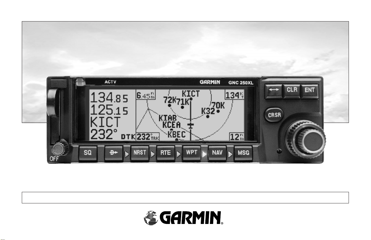
GNC 250XL
Pilot’s Guide and Reference
Page 2

Page 3

Software Version 2.01 or above
© 1997 GARMIN Corporation
1200 East 151st Street, Olathe, Kansas 66062-3426, USA
INTRODUCTION
Foreword
GARMIN (Europe) LTD, Unit 5, The Quadrangle, Abbey Park Industrial Estate,
Romsey S051 9AQ, UK
Web Site Address: www.garmin.com
All rights reserved. No part of this manual may be reproduced or transmitted in any
form or by any means, electronic or mechanical, including photocopying and recording, for any purpose without the express written permission of GARMIN.
Information in this document is subject to change without notice. GARMIN reserves
the right to change or improve their products and to make changes in the content of
this material without obligation to notify any person or organization of such changes
or improvements.
March 1997 190-00067-60 Rev. A Printed in USA
GARMIN, GNC 250XL, Spell’N’Find, AutoLocate,
PhaseTrac12, GPSCOM and AutoStore are
trademarks of GARMIN and may only be used
with permission.
NavData®is a registered trademark of
Jeppesen, Inc.
All rights reserved.
i
Page 4

INTRODUCTION
Cautions
The Global Positioning System is operated by the United States government,
which is solely responsible for its accuracy and maintenance. The system is subject to
changes which could affect the accuracy and performance of all GPS equipment.
NOTE: This device complies with Part 15 of the FCC
limits for Class B digital devices. This equipment generates, uses, and can radiate radio frequency energy and, if
not installed and used in accordance with the instructions, may cause harmful interference to radio communications. Furthermore, there is no guarantee that interference will not occur in a particular installation.
If this equipment does cause harmful interference, the
user is encouraged to try to correct the interference by relocating the equipment or connecting the equipment to a different circuit than the affected equipment. Consult an
authorized dealer or other qualified avionics technician for
additional help if these remedies do not correct the problem.
Operation of this device is subject to the following
conditions: (1) This device may not cause harmful interference, and (2) this device must accept any interference
received, including interference that may cause undesired
operation.
The GARMIN GNC 250XL does not contain any
user-serviceable parts. Repairs should only be made by an
authorized GARMIN service center. Unauthorized repairs
or modifications could void your warranty and authority
to operate this device under Part 15 regulations.
ii
Although the GARMIN GNC 250XL is a precision electronic NAVigation AID
(NAVAID), any NAVAID can be misused or misinterpreted and therefore become
unsafe.
Use the GNC 250XL at your own risk. To reduce the risk of unsafe operation,
carefully review and understand all aspects of this Owner’s Manual and thoroughly
practice using the simulator mode prior to actual use. When in actual use, carefully
compare indications from the GNC 250XL to all available navigation sources, including the information from other NAVAIDS, visual sightings, charts, etc. For safety,
always resolve any discrepancies before continuing navigation.
The altitude calculated by the GNC 250XL is geometric height above mean sea
level and could vary significantly from altitude displayed by pressure altimeters in aircraft. Never use GPS altitude for vertical navigation.
The Jeppesen database incorporated in the GNC 250XL must be updated regularly in order to ensure that its information is current. Updates are released every 28
days. A database information packet is included in your GNC 250XL package.
Pilots using an out-of-date database do so entirely at their own risk.
CAUTION
Page 5

Accessories & Packing List
Congratulations on choosing the finest, most advanced panel mount VFR
GPSCOM available. The GNC 250XL represents GARMIN’s commitment to provide
an accurate, easy-to-use GPS for all of your aviation needs.
Before installing and getting started with your unit, please check to see that your
package includes the following items. If any parts are missing or damaged, please see
your GARMIN dealer immediately.
INTRODUCTION
Accessories and
Packing List
Standard Package:
• GNC 250XL Unit & NavData® Card
• GPS Antenna
• Installation Rack & Connectors
• Pilot’s Guide & Quick Reference Guide
• Database Subscription Packet
• Warranty Registration Card
Optional Accessories:
• Remote Battery Pack
• AC Adapter
• PC Software/Interface Kit
• User Data Card
• 28 to 14 volt DC converter
To obtain accessories for your GNC 250XL,
please contact your nearest GARMIN dealer.
iii
Page 6

INTRODUCTION
Warranty
To obtain warranty service, see your local dealer
or call the GARMIN Customer Service department
for a returned merchandise tracking number. The
unit should be securely packaged with the tracking
number clearly marked on the outside of the
package, and sent freight prepaid and insured to a
GARMIN authorized warranty service facility.
GARMIN is fully committed to your satisfaction as
a customer. If you have any questions regarding
the GNC 250XL, please contact our customer
service department at:
GARMIN International, Inc.
1200 East 151st Street
Olathe, KS 66062-3426
(913) 397-8200
FAX (913) 397-8282
Every GARMIN GPS is built to exacting standards to provide years of
trouble-free service. GARMIN warrants this product to be free from defects
in materials and workmanship for one year from the date of purchase.
GARMIN International, Inc. will at its sole option, repair or replace any
components which fail in normal use. Such repairs or replacement will be
made at no charge to the customer for parts or labor. The customer is, however, responsible for any transportation costs. This warranty does not cover
failures due to abuse, misuse, accident or unauthorized alteration or repairs.
GARMIN International, Inc. assumes no responsibility for special, incidental,
punitive or consequential damages, or loss of use.
THE WARRANTIES AND REMEDIES CONTAINED HEREIN ARE
EXCLUSIVE, AND IN LIEU OF ALL OTHER WARRANTIES EXPRESSED OR
IMPLIED, INCLUDING ANY LIABILITY ARISING UNDER WARRANTY OF
MERCHANTABILITY OR FITNESS FOR A PARTICULAR PURPOSE,
STATUTORY OR OTHERWISE. THIS WARRANTY GIVES YOU SPECIFIC
LEGAL RIGHTS, WHICH MAY VARY FROM STATE TO STATE.
iv
Page 7

PART ONE: INTRODUCTION
Foreword . . . . . . . . . . . . . . . . . . . . . . . . . . . . . . . . . . . . . . . . . . . . . . . . . .i
Cautions . . . . . . . . . . . . . . . . . . . . . . . . . . . . . . . . . . . . . . . . . . . . . . . . . .ii
Accessories/Packing List . . . . . . . . . . . . . . . . . . . . . . . . . . . . . . . . . . . . . . .iii
Warranty . . . . . . . . . . . . . . . . . . . . . . . . . . . . . . . . . . . . . . . . . . . . . . . . . .iv
Table of Contents . . . . . . . . . . . . . . . . . . . . . . . . . . . . . . . . . . . . . . . . . .v-vi
Key and Knob Functions . . . . . . . . . . . . . . . . . . . . . . . . . . . . . . . . . . .vii-viii
GNC 250XL Takeoff Tour . . . . . . . . . . . . . . . . . . . . . . . . . . . . . . . . . . .1-10
PART TWO: REFERENCE
Section 1: Navigation with the GNC 250XL ( Nkey) . . . . . . . . . . . . . . .11
Navigating and planning functions
Section 2: Communicating with the GNC 250XL . . . . . . . . . . . . . . . . . . .33
Using the GNC 250XL’s radio
Section 3: Waypoint and Database Information ( Wkey) . . . . . . . . . . . .37
Finding and using database and waypoint information
Section 4: Nearest Waypoints ( Tkey) . . . . . . . . . . . . . . . . . . . . . . . . .57
Finding nearest waypoints, SUAs and FSS/ARTCC frequencies
Section 5: Direct-to ( Dkey) & Route Navigation ( Rkey) . . . . . . . .62
Creating and using routes
INTRODUCTION
Table of Contents
To quickly and easily locate information
on specific tasks, please refer to the Index
on page 103.
v
Page 8

INTRODUCTION
Table of Contents
Section 6: Messages and Unit Settings ( Mkey) . . . . . . . . . . . . . . . . . .75
Appendix A: NavData®and User Data Card Use . . . . . . . . . . . . . . . . .87
Appendix B: Installation and Maintenance of the GNC 250XL . . . . . . . .89
Appendix C: Simulator . . . . . . . . . . . . . . . . . . . . . . . . . . . . . . . . . . . .90
Appendix D: GNC 250XL Messages and Abbreviations . . . . . . . . . . . . .92
Appendix E: Specifications . . . . . . . . . . . . . . . . . . . . . . . . . . . . . . . . .100
Appendix F: Map Datums . . . . . . . . . . . . . . . . . . . . . . . . . . . . . . . . .101
Appendix G: Index . . . . . . . . . . . . . . . . . . . . . . . . . . . . . . . . . . . . . .103
vi
Page 9

B
Key and Knob Functions
The power/volume knob controls unit power and radio volume.
INTRODUCTION
Key and Knob
Functions
Q
D
T
R
W
N
The squelch button activates automatic squelch control.
The direct-to key performs an instant direct-to, allows you to enter a
waypoint, and sets a direct course to the destination.
The nearest key is used to obtain information on the 9 nearest airports,
VORs, NDBs, intersections, user waypoints and 2 nearest FSS/ARTCC
points of communication. The nearest key also accesses any active SUA
information. See Section 4 for more information on the nearest waypoints.
The route key enables you to create, edit, activate and invert routes. Searchand-rescue, parallel offset and closest point of approach functions are also
performed using the route key. See Section 5 for more route information.
The waypoint key is used to view information such as runways, frequencies, position and comments on airports, VORs, NDBs, intersections and
user waypoints. See Section 3 for more waypoint information.
The navigation key is used to view navigation and position information.
Planning operations are also performed using this key. See Section 1
for more information on navigation and planning operations.
The GNC 250XL is designed to minimize
keystrokes when performing operations. There are
typically several ways to perform the same operation. In general, using the knobs will decrease keystrokes and time spent using the GNC 250XL.
Experiment to find the most effective way to use
the GNC 250XL to your advantage.
vii
Page 10

INTRODUCTION
Key and Knob
Functions
M
@
The message key is used to view system messages. This key is also used to
access the GNC 250XL’s unit settings. See Section 6 for more information
on messages and unit settings.
The transfer key flip-flops the active and standby frequencies.
viii
This manual will describe entering data using the
and Oknobs. Experiment with them and become efficient
in entering data with the concentric knobs. This will greatly
reduce the amount of time required to navigate with the
GNC 250XL.
K
\
E
C
O
K
The clear key is used to erase information or cancel an entry.
The enter key is used to approve an operation or complete data entry.
It is also used to confirm information, such as during power on.
The cursor key is used to activate or deactivate the cursor in the separate
areas of the GNC 250XL. Pressing once will activate the cursor in the
comm ‘window’ and enable the pilot to change frequencies. Pressing twice
will activate the cursor in the GPS window (indicated by highlighted
characters in a GPS window field). It is used to highlight fields for data
entry, changing information or cycling through available options.
The outer knob is used to advance through pages, advance the cursor
or move through data fields.
The inner knob is used to change data or scroll through information that
cannot fit on the screen all at once.
Page 11

The GARMIN GNC 250XL is a powerful navigational tool that provides pilots with accurate
navigational data and communication capability, along with a host of database information at your
fingertips. The Takeoff Tour is designed to familiarize you with the operation of the GNC 250XL,
including powering up the unit, changing frequencies, entering data and performing a simple
direct-to, and a limited introduction to the ‘Nearest’ functions. In addition, this section also briefly
covers the position, CDI and frequency pages available from the NAV key. These pages will be
used for most of your in-flight navigation.
The Takeoff Tour assumes that the GPSCOMTMand antennas have been properly
installed and you have not changed any of the GNC 250XL’s default settings. If you have
changed any of the factory default settings (position format, units of measure, selectable
fields, etc.), the pictures used may not match your configuration. Prior to using your GNC
250XL for the first time, we recommend that you taxi to a location that is well away from
buildings and other aircraft so the unit can collect satellite data without interruption.
Powering up the GNC 250XL
The GNC 250XL’s power and volume are controlled using the B(power/volume) knob
The welcome page appears when the GNC 250XL
is turned on. During the time this screen is
displayed, the GNC 250XL performs a self test to
ensure proper operation
at the bottom left of the unit. Rotating it clockwise will turn the unit on and increase the
radio volume. After turning the unit on, a welcome page will be displayed while the unit
performs a self test.
The database page will appear, showing the current database information on the NavData
card, with the valid operating dates, cycle number and database type indicated. The database is
updated every 28 days and is available for one-time or subscription purchase.
TAKEOFF TOUR
Power On
To acknowledge the database information:
E key
1. Press the
.
The database confirmation page shows the
effective date of the Jeppesen database on the
NavData Card.
1
Page 12

TAKEOFF TOUR
Acquiring Satellites
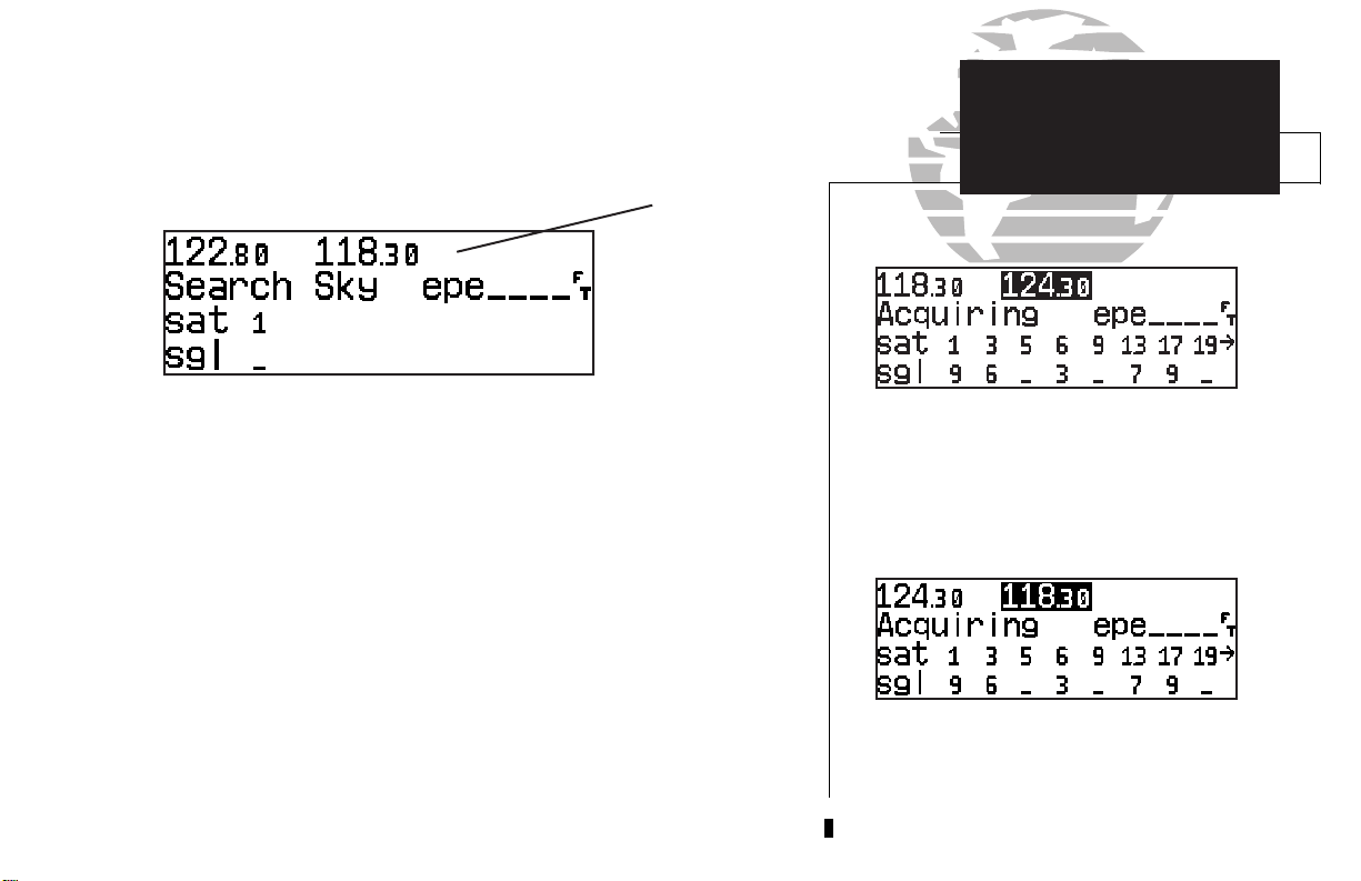
Once the database has been acknowledged, the satellite status page will appear,
and the GNC 250XL will begin to collect satellite information. An ‘Acquiring’ status
will be displayed on the satellite status page, and the signal values on the bottom line
of the page will begin displaying numeric values. This is a good indication that you
are receiving signals and satellite lock will occur. Following the first-time use of your
GNC 250XL, the time required for a position fix will vary — usually from two to five
minutes.
If the unit can only obtain enough satellites for 2D navigation (no altitude), the
unit will use the altitude provided by your altitude encoder (if one is connected and
working). If not, you will be prompted to enter the altitude with a ‘Need alt- Press
NAV’ message. If this message occurs, press the Nkey and use the Kand
O
knobs to enter the altitude shown on your altimeter. Press Ewhen finished.
The satellite status page shows the ID numbers for
the satellites and the relative signal strength of
each satellite received. Turn the K knob to view
additional satellites.
If the GNC 250XL has not been operated for a period of six months or more, it
may have to ‘Search the Sky’ to collect new data. This means the unit is acquiring
satellite data to establish almanac and satellite orbit information, which can take 5 to
10 minutes. The satellite status page will display a ‘Search Sky’ status, and the
message annunciator (U), next to the Mkey, will also flash to alert you of a system
message — ‘Searching the Sky’.
To view a system message
1. Press M.
:
The message page will appear and display the status or warning information
applicable to the receiver’s current operating condition.
‘Search Sky’ indicates that satellite almanac data
is not available or has expired (if the unit hasn’t
been used for six months or more). The data will
be recollected from the first available satellite.
2
To return to the previous page after viewing a message
1. Press Magain.
:
Page 13
While the GNC 250XL is acquiring a position, let’s take a minute to dial in the
active and standby frequencies you’ll be using for the first phase of your flight. The
GNC 250XL’s display can be broken down into two separate ‘windows’, the comm
window (the top line of the display) and the GPS window (the bottom three lines of
the display).
Active
Standby
Comm Window
TAKEOFF TOUR
Selecting Comm Frequencies
{
{
The Ckey is used to activate the cursor in a particular window (see right) to
provide access to various comm and navigation features. To select the active frequency,
you must first enter the frequency in the standby field, and use the @key to move it
to the active field.
To change the standby communication frequency:
1. Press Conce to activate the cursor in the comm window.
2. Rotate the outer knob (
the desired frequency.
To place the standby frequency in the active field, press
Once you’ve entered the active frequency, simply repeat steps 1 and 2 to enter the
standby frequency. After both frequencies have been entered, you may elect to keep
the comm window ‘hot’ by leaving the cursor on the standby frequency, or remove the
cursor by pressing the Ckey twice.
O
) to select the MHz, and the inner knob (K) to select the kHz of
}
GPS Window
}
@
.
Status page with cursor active in comm window.
To switch the active and standby frequencies, press
the @ key. Switching the active and standby
frequencies will not remove the cursor from the
comm window.
3
Page 14
TAKEOFF TOUR
Position Page
After the GNC 250XL acquires satellites and computes a position, the position page will
appear automatically, and you’ll be informed with ‘Ready for navigation’ on the message page.
Altitude, MSA or ESA
Position (lat/lon)
Reference Waypoint Field
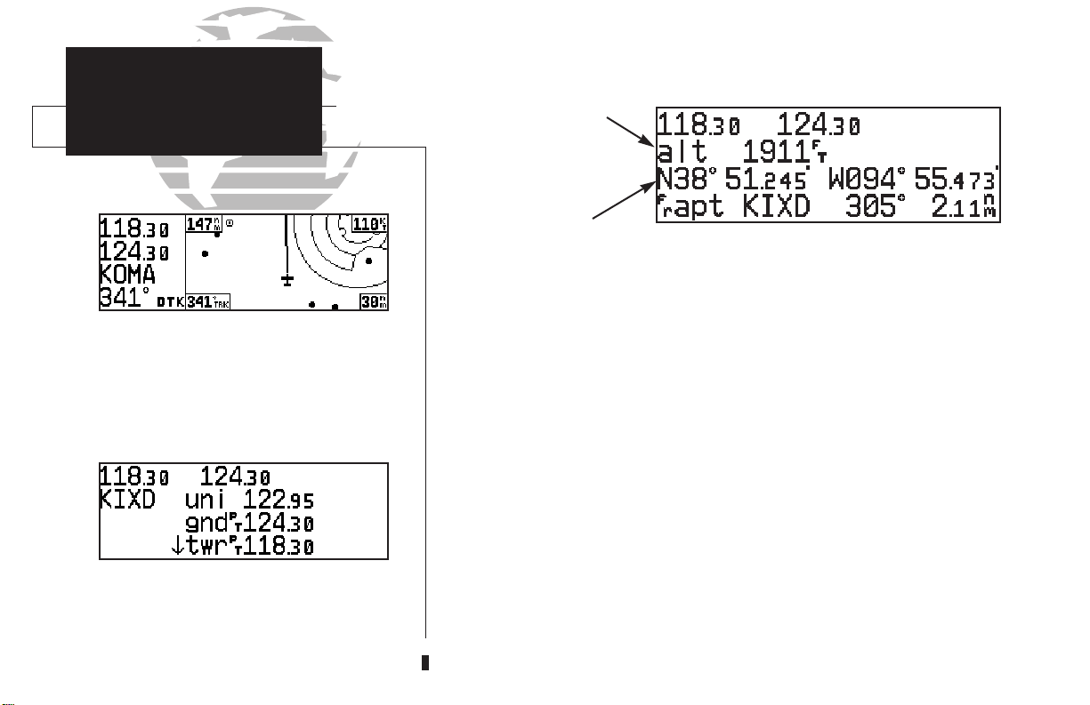
The position page displays your present latitude and longitude, altitude and a reference way-
point field. The altitude and reference waypoint fields are also selectable (see Section 1 for more
The map page combines a moving map display
and navigation data for complete situational
awareness.
The navigation communications (NAVCOM) page
provides a complete list of airport frequencies at
your departure and arrival airports.
4
information) to allow you to configure the unit to your own preferences. The default settings are:
• Altitude— Your present GPS altitude
• Present Position— Latitude and longitude displayed in degrees/minutes
• Reference Waypoint— The bearing and distance to the nearest airport
The position page is one of seven pages available under the GNC 250XL’s Nkey:
• CDI page • Map page
• NAVCOM page • Position page
• Satellite status page • NAV menu 1
• NAV menu 2
During most flights, the Position, CDI (course deviation indicator), Map and NAVCOM pages
will be the primary pages used for navigation. These pages are accessible by pressing the Nkey
and rotating the outer knob, or by pressing the Nkey repeatedly.
{
Page 15
The GNC 250XL uses direct point-to-point navigation to guide you from takeoff
to touchdown in the VFR environment. Once a destination is selected, the unit will
provide speed, course and distance data based upon a direct course from your present
position to your destination. A destination can be selected from any page with the
D
(direct-to) key.
To select a direct-to destination:
D
1. Press the
key. The CDI page will appear with the destination field highlighted.
TAKEOFF TOUR
Direct-To
Navigation
2. Rotate the
tination waypoint may be an airport, VOR, NDB, intersection or user waypoint, as long as
it is in the database or stored in memory as a user waypoint.
3. Rotate the
4. Repeat steps 2 and 3 to spell out the rest of the waypoint identifier.
5. Press
6. Press
K
knob to enter the first letter of the destination waypoint identifier. The des-
O
knob to the right to move the cursor to the next character position.
E
to confirm the identifier. The direct-to confirmation page will appear.
E
to confirm the destination.
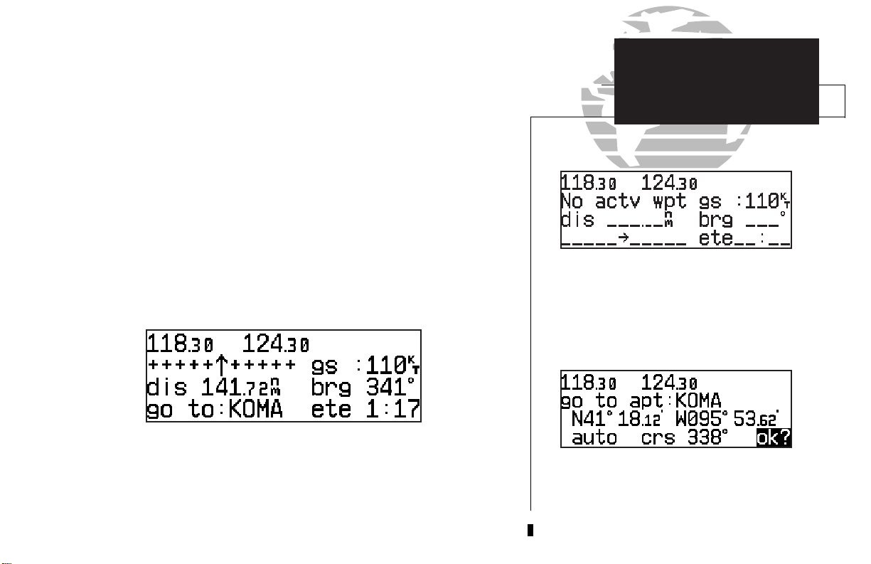
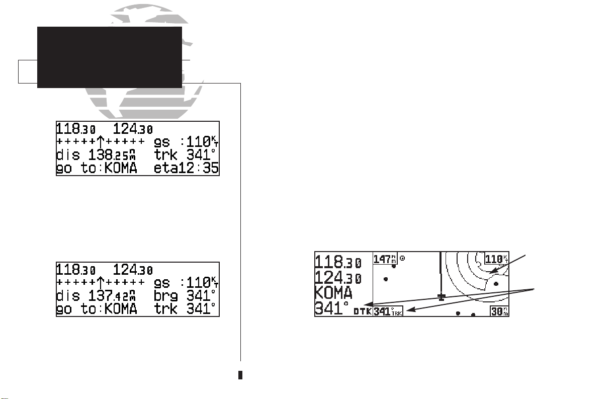
Once the direct-to destination is confirmed, the CDI page will appear with the
destination indicated in the lower left hand corner of the screen. Your present speed
and track over the ground, and the distance and estimated time enroute to your destination are also displayed. The graphical CDI, located at the top left of the screen, displays your position relative to the desired course and provides turn anticipation and
waypoint messages during route navigation.
The CDI page without a direct-to destination or
active route appears blank, except for ground
speed (GS) and track (TRK) figures.
When a destination is selected the direct-to
confirmation page appears to verify the
destination you selected.
5
Page 16
TAKEOFF TOUR
CDI & Map Pages
CDI page with ‘trk’ and ‘eta’ displayed.
In addition to the destination field and graphical CDI, the GNC 250XL CDI page
features four selectable fields for various navigation data so that the page may be configured to your own preferences (see Section 1 for more information). The default settings for the CDI page are:
• Ground Speed (gs)— Your present speed over the ground in knots
• Distance (dis)— The distance to your destination in nautical miles
• Desired Track (dtk)— The course between active from and to waypoints
• Estimated Time Enroute (ete)— The time to your destination based
upon your present speed and course in hours and minutes
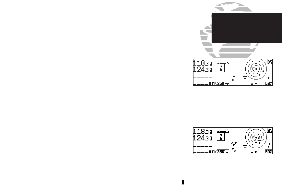
The next page available from the Nkey is the map page. The map page combines the primary navigation information from the CDI page – distance to waypoint,
ground speed and track – with a moving map display. The moving map display shows
your current position (using an airplane symbol or a diamond symbol) relative to nearby airports, VORs, NDBs, intersections, user waypoints and airspace boundaries.
The map page can be divided into three main sections:
Map Display
Comm
Frequencies
{
Data Fields
CDI page with ‘brg’ and ‘trk’ displayed.
6
The communication frequencies are located in the upper left corner of the page,
instead of across the top line as on other pages. The top frequency is the active frequency, with the standby frequency directly below.
Page 17
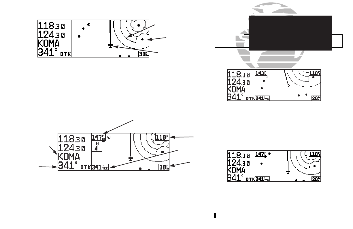
Airspace
Boundaries
Airport Waypoint
Present
Position
The map display occupies the right side of the display. Your present position is indicated by a plane symbol (in track up mode) or a position diamond (in other orientation modes), with your route displayed as a solid line. Nearby airports, navaids and
user waypoints may be depicted on the map; with unique identifying symbols for
each waypoint type. Boundaries for special use and controlled airspaces can also
appear on the map display. You may select which features are shown on the map
using the map setup page (see page 76).
Distance to Waypoint
Destination
Waypoint
GS
TRK
TAKEOFF TOUR
Map Page
The map display may be oriented along your
ground track (track up), course (desired track up)
or fixed at north up. Desired track up or north up
settings show your present position with a diamond symbol instead of the airplane symbol.
DTK
Map
Scale
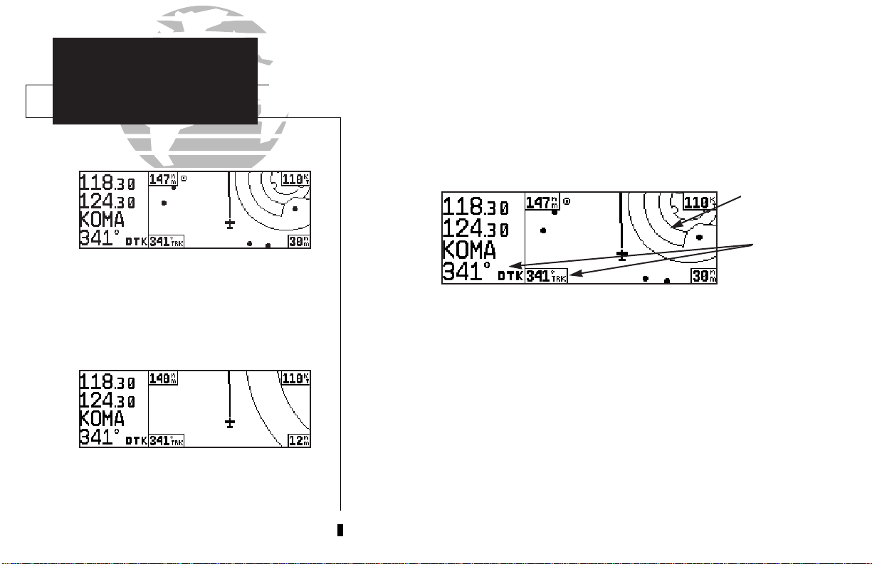
The data fields on the map page indicate distance to destination waypoint,
desired track, ground track, ground speed and map scale. The destination waypoint
name and desired track appear on the left side of the page, below the communication
frequencies. The other data fields are located at the corners of the map display as
shown in the illustration above, and may be removed by pressing \.
Communication frequencies are shown in the top
left corner of the map page, instead of across the
top line as shown on other GNC 250XL screens.
7
Page 18
TAKEOFF TOUR
Map Scales
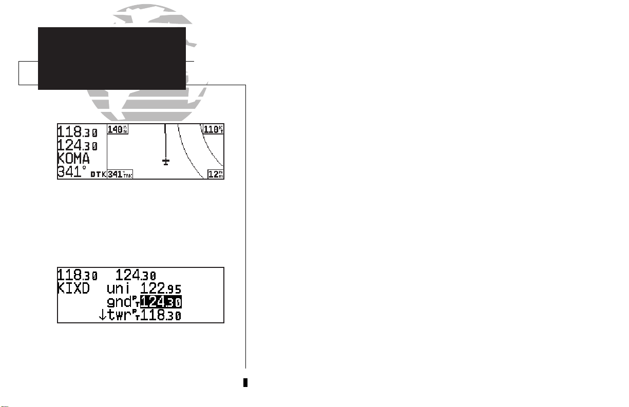
NAVCOM Page
To change the map scale rotate the K knob clock-
wise to increase the scale or counterclockwise to
decrease the scale.
The map display has 14 available ranges from 0.5 to 300 (nautical miles, statute miles
or kilometers) representing the vertical height of the map. The map scale is controlled by the inner knob (K), with the current scale displayed in the lower right
corner of the page.
To select a map scale:
K
1. Rotate the
2. Rotate the
knob clockwise to increase the map scale and show a larger area.
K
knob counterclockwise to decrease the map scale and show a smaller area.
Another page available under the GNC 250XL’s Nkey is the navigation
communications (NAVCOM) page. It provides you with a complete list of airport
frequencies at your departure and arrival airports, allowing convenient selection of
frequencies you’ll need along your flight path. If you do not have an active departure
airport, the navigation communications page will display the frequencies for the
airport nearest your departure position.
To view the NAVCOM page from the map page, rotate Oone stop to the right.
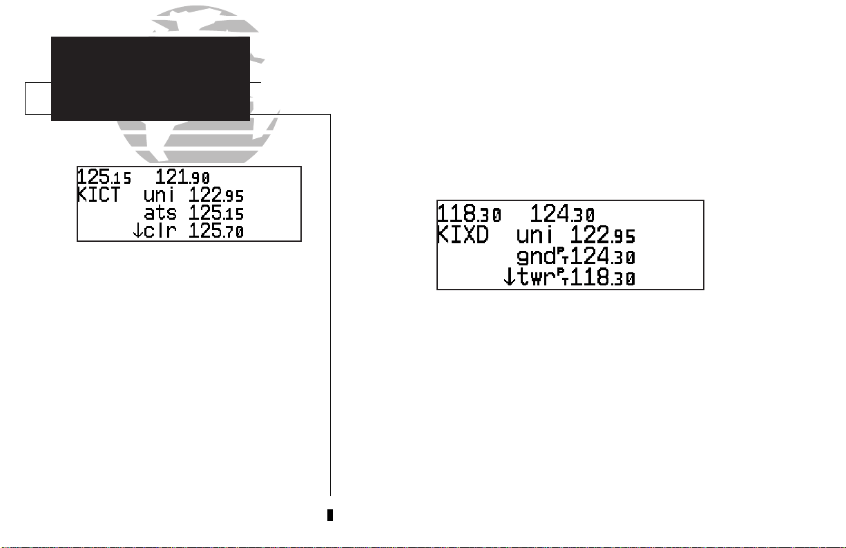
The NAVCOM page lists your departure and arrival airports on the left side of the
page, with all the database frequencies listed in a column down the right side of the
page. To scroll through the list of frequencies, simply rotate the inner knob (K) in
the direction of the arrow prompts at the bottom left of the page.
To place a frequency from the list in the standby field:
The NAVCOM page lists the frequencies for your
departure and arrival airports. To place a frequency from this list on standby, highlight the
desired frequency and press E.
8
1. Press the
2. Use the
C
key twice to activate the cursor in the GPS window.
O
knob to select the desired frequency. Press Eto place the frequency in
the standby field. The cursor will automatically advance to the next frequency on the list.
Page 19
Once a direct-to is activated, the CDI page will provide navigation to the destina-
tion until the direct-to is cancelled or another direct-to destination is activated.
To cancel a direct-to from the CDI page:
1. Press the
2. Press
3. Press
C
key twice to activate the cursor in the destination field.
\
.
E
.
The GNC 250XL’s Tkey provides the nine nearest airports, VORs, NDBs, intersections, user waypoints and any SUA (special use airspace) alerts, as well as the two
closest FSS (Flight Service Station) and center (ARTCC) frequencies for your present
position. The nearest waypoint feature is a handy safety feature that may be used to
execute a quick direct-to in case of an in-flight emergency or to review the closest facilities to your present position. The nearest feature can also be used to quickly find the
contact frequency of the nearest airport and enter it in the standby field.
TAKEOFF TOUR
Cancelling a Direct-To
Nearest Waypoints
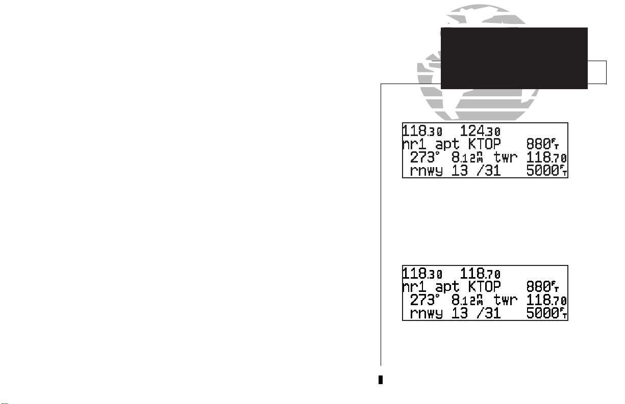
The nearest airport page shows up to nine
nearest airports from your present position.
To view the nine nearest airports
1. Press the Tkey. The nearest airport will be displayed, with the range and bearing from
your present position, along with elevation, frequency and runway data.
2. To review the rest of the nearest airport list, rotate the
To place a nearest airport frequency in the standby field
1. PressE. Press the @key to place the frequency in the active field.
To view the nearest list for other waypoint categories (VOR, NDB, etc.)
1. Rotate the Oknob to the right, or press the Tkey repeatedly.
2. Rotate Kto scroll through the list.
:
K
knob to the right.
:
:
To place a nearest airport frequency in the standby field, press E.
9
Page 20
TAKEOFF TOUR
Nearest Airports
Shutting Down
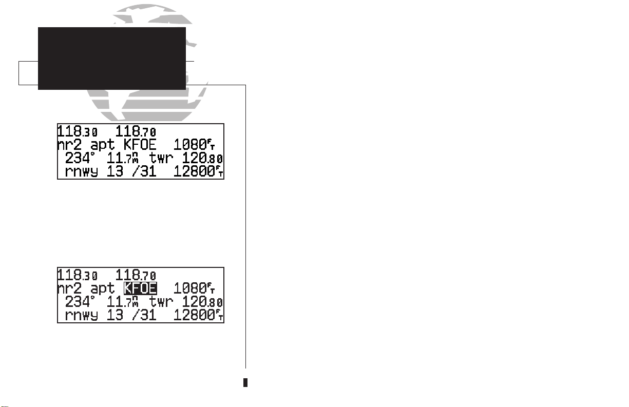
Once the nearest airport (or any other nearest waypoint) page is displayed, the
selected waypoint can be quickly reviewed or selected as a direct-to destination.
To review the selected waypoint from the nearest waypoint list
1. Press Ctwice to activate the waypoint field.
2. Press Eto display the waypoint identification page.
3. Rotate Oto view any additional waypoint information available.
4. Press Tto return to the nearest waypoint page.
:
To view additional nearest airports, rotate the
K knob.
To select a nearest waypoint as a direct-to destination
1. Press the Dkey. The direct-to confirmation page for the selected waypoint will appear.
2. Press Eto confirm.
Congratulations! You’ve now gone through the basic operation of the GNC 250XL.
:
We encourage you to experiment with your new GPSCOM to get to know all the
advanced navigation features it has to offer. If you’d like a little more practice, try
using the built-in simulator described in Appendix C. An optional AC adapter will
even let you plan and simulate flights in the comfort of your home or office.
To turn the GNC 250XL off
1. Turn the Bknob to the left until the unit shuts off.
To review a nearest waypoint, highlight the identifier and press E.
10
:
Page 21
Section 1
Navigation Key
The GNC 250XL features seven navigation pages to provide various position,
course, speed, status and planning information. The pages may be viewed by pressing
the Nkey and rotating the outer knob, or by pressing the Nkey repeatedly.
CDI page
Map page
NAVCOM page
NAV KEY
Overview
SECTION
1
NAV Menu 2
NAV Menu 1
The CDI, map, NAVCOM and position pages are the primary pages used during
in-flight navigation, while the nav menu and status pages offer access to planning,
calculation and status functions. Note that rotating the outer knob clockwise will
continuously cycle through all the nav pages, whereas turning the knob counterclockwise will stop the page selection sequence at the CDI page.
Whenever the Nkey pages are in use, the indicator light (U) next to the
key will illuminate. If the GNC 250XL requires you to enter data on a navigation
page, a message prompt with specific instructions will appear and the indicator will
flash. If you leave the NAV page sequence for another set of pages, the last NAV page
displayed will appear when you return to the nav sequence.
Satellite status page
Position page
N
Remember! The NAV pages will only display information
AFTER the position and navigational information has been
calculated from the satellites. If you are on the Position
page before the unit has calculated a position, you will be
able to enter an approximate position and altitude. This is
helpful in speeding satellite acquisition if the unit has
moved a great distance with the power off.
If you are not sure the GPS is actively calculating position,
check the receiver status field for ‘2D NAV’ or ‘3D NAV’ by
pressing the
Satellite Status page appears. The current receiver status is
displayed at the top left of the page.
N
key and rotating the outer knob until the
11
Page 22
SECTION
1
NAV KEY
CDI Page
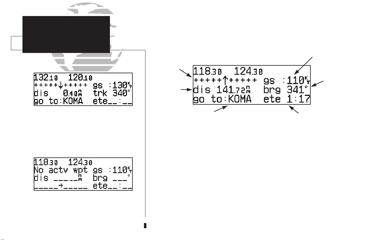
The GNC 250XL’s CDI page provides you with the important information needed
to navigate directly to your destination. The destination field, located at the bottom
left of the page, displays the current destination waypoint or active route leg being
navigated. If no direct-to destination or route is being navigated, the destination field
will remain blank.
Ground Speed
Messages
or CDI
Direction
Distance
Field
Field
The TO/FROM arrow indicates whether you are
heading to (an up arrow) the waypoint or if
you’ve passed the waypoint (a down arrow).
The graphical CDI (course deviation indicator) at the top left of the page shows
your position relative to the desired course (the moving D-bar) to the destination
waypoint. The TO/FROM arrow in the center of the scale indicates whether you are
heading to (an up arrow) the waypoint or if you have passed the waypoint (a down
arrow). The default setting of the CDI scale is 5.0 nm. If you are not navigating to a
destination, the CDI field will display a ‘no actv wpt’ message, and only speed and
track data will be available. The CDI field is also used to display the GNC 250XL’s
turn anticipation and waypoint alert data during route operations (see section 5).
The CDI page will display ‘No actv wpt’ in the
CDI field if there is no destination waypoint
selected using the D key and no active route.
12
In addition to displaying your active destination and the course deviation scale,
the CDI page features four selectable fields for various distance, direction and time
options. This allows you to configure the CDI page to your preferences. The default
settings are ground speed, distance, desired track and estimated time enroute.
Active Waypoint
Time or Direction Field
Page 23

WPT 1
S
T
R
L
NORTH
NORTH
WPT 2
BRG
TRK
G
S
DIS
A
IR
P
L
A
N
E
D
T
K
The following functions may be displayed in the ground speed field:
• gs— Your present speed over the ground.
• str— Steer direction and distance, or digital crosstrack error. An ‘L’ or ‘R’
indicates which direction to steer, while the distance value indicates how far you are off course.
The following functions may be displayed in the distance field:
• dis— Distance from present position to the ‘active to’ waypoint.
• str— Steer direction and distance, or digital crosstrack error. An ‘L’ or ‘R’
indicates which direction to steer, while the distance value indicates how far you are off course.
The following steering functions may be displayed in the direction field:
• brg— Bearing, the direction from your present position to the waypoint.
• cts— Course to steer to reduce cross track error and re-intercept course.
• dtk— Desired track, the course between the active from and to waypoints.
• trk— Track, the direction of movement relative to the ground.
• trn— Turn, the direction and degrees to turn to get back on course.
The following information can be displayed in the time field:
• eta— Estimated Time of Arrival (at the active to waypoint).
• ete— Estimated Time Enroute (to the active to waypoint).
• trk— Track, or the direction of movement relative to the ground.
• vn— Vertical Navigation, or VNAV. If VNAV has been activated, this field
indicates either the elapsed time before the VNAV maneuver is to
begin or the VNAV altitude (the suggested altitude you should be flying in order to complete the maneuver).
NAV KEY
Configuring the
CDI Page
SECTION
1
13
Page 24
SECTION
NAV KEY
CDI &
1
On the map page the active and standby communication frequencies are in the upper left corner of
the page. The active frequency is on top.
To change the map scale rotate the K knob clockwise to increase the scale or counterclockwise to
decrease the scale.
Map Pages
To change any of the selectable fields on the CDI page:
1. Press Ctwice to activate the cursor in the GPS window.
2. Rotate Oto highlight the field you would like to change.
3. Rotate Kto change the field to display the desired information.
4. Rotate Oto highlight another field, or Cto finish.
Map Display
Comm
Frequencies
{
Data Fields
The next page available from the GNC 250XL’s Nkey is the map page. The
map page displays your present position, using an airplane symbol (in track up
mode) or a position diamond (in other orientation modes), along with nearby airports, VORs, NDBs, intersections, user waypoints and airspace boundaries. Note: If
the GNC 250XL is unable to determine a GPS position the present position symbol
will not appear on the map page.
The top left corner of the page indicates the active and standby communications frequencies — unlike other GNC250XL screens which display both frequencies across the top line — with the active frequency on top.
14
Page 25
The map display occupies the right side of the display and shows your position
relative to nearby airports, navaids, user waypoints and airspaces. Different symbols
are used to distinguish between waypoint types. The identifiers for any on-screen
waypoints can also be displayed. Special-use and controlled airspace boundaries
appear on the map, showing the individual sectors in the case of Class B or Class C
airspace. The map display can be configured to display airports, navaids, user waypoints, airspaces only at certain scales or these items may be disabled entirely (see
page 76). This allows you to de-clutter the map display at larger scale settings.
The map display can be set to 14 different scale settings from 0.5 to 300 (nautical
miles, statute miles or kilometers). The scale represents the top-to-bottom distance
covered by the map display.
NAV KEY
Map Page
SECTION
1
To select a map scale:
K
1. Rotate the
2. Rotate the
The autozoom feature will automatically adjust from an en route scale of 300
through each lower scale, stopping at a scale of 1 as you approach your destination
waypoint. The autozoom feature is turned on/off from the map setup page described
on page 76.
The orientation of the map may be fixed at ‘north up’, or set to ‘desired track up’
(dtk up) or ‘track up’ (trk up). The ‘north up’ setting will keep the top of the map
display fixed on north. ‘Track up’ will cause the map to rotate so the top of the map
is the direction you are heading. ‘Desired track up’ keeps the map display fixed along
your desired course. Map orientation is changed on the map setup page described on
page 76.
knob clockwise to increase the map scale and show a larger area.
K
knob counterclockwise to decrease the map scale and show a smaller area.
The map page, showing only airports and airspaces on the map display.
The map page, showing airports, airspaces, VORs
and NDBs on the map display. The data fields
located at the corners of the map display may be
removed by pressing \.
15
Page 26
Navigation data is also provided on the map page to guide you during your flight.
SECTION
NAV KEY
Map &
1
The NAVCOM page lists the frequencies for your
departure (or nearest) and arrival airports in the
following order:
Departure Arrival
• Unicom • ATIS
• ATIS • Approach
• Clearance Delivery • Arrival
• Clearance Pretaxi • TCA
• Ground • TMA
• Tower • CTA
• Multicom • ARSA
• Other • TRSA
• Departure • Tower
• TCA • Multicom
• TMA • Other
• CTA • Ground
• ARSA • Unicom
• TRSA
16
NAVCOM Pages
The destination waypoint name and desired track (dtk) appear on the left side of the
page, below the communication frequencies. Additional data fields may be displayed
at the corners of the map display (or removed by pressing \), as follows:
Distance (dis) to waypoint - upper left corner
Ground speed (gs) - upper right corner
Ground track (trk) - lower left corner
Map scale - lower right corner (cannot be removed)
The next page available from the GNC 250XL’s Nkey is the navigation com-
munications (NAVCOM) page. The NAVCOM page provides a list of the airport
frequencies at your departure and arrival airports, allowing convenient selection of
frequencies you’ll need along your flight path. To scroll through the list of frequencies, rotate the inner knob (K) in the direction of the arrow prompts at the bottom
left of the page.
The frequencies displayed for the departure and arrival airports are listed in the
order you are most likely to use them (see left), with the available frequencies displayed to the right of the airport identifier. If you do not have an active route with a
departure airport, the NAVCOM page will display the frequencies for the airport
nearest your departure position.
Page 27

If a frequency has sector or altitude restrictions, the frequency will be followed by
a ‘brg?’ indication.
To view restrictions on a frequency:
1. Press Ctwice to activate the cursor in the GPS window.
2. Rotate Oto highlight the ‘brg?’ next to the frequency you wish to view.
E
3. Press
Once you begin viewing restrictions, you can view any additional frequencies for
the selected airport by rotating K. (Note: An arrow prompt displayed next to the airport identifier indicates additional frequencies are available.) You can also view the
other airport information pages by rotating O. Information contained on these pages
is covered in Section 3. To return to the NAVCOM page, press N.
Some frequencies in the NAVCOM page have tags which designate their usage:
‘tx’ – transmit only ‘rx’ – receive only
‘pt’ – part time frequency
To make any of the frequencies on the NAVCOM page the standby frequency:
1. Press Ctwice to activate the cursor in the GPS window.
2. Rotate
to begin viewing restrictions.
O
until the desired frequency is highlighted.
NAV KEY
SECTION
NAVCOM Page
NAVCOM page with receive only (rx) frequencies
and frequencies with restrictions (brg).
1
E
3. Press
matically advance to the next frequency on the list.
to make the highlighted frequency the standby frequency. The cursor will auto-
Frequency restrictions on 124.60, showing range
of applicable radials from 130º through 309º.
17
Page 28

SECTION
1
NAV KEY
Position Page
The GNC 250XL position page displays your present latitude and longitude,
altitude and a reference waypoint field. The altitude and reference waypoint fields are
selectable to configure the page to your own preferences and current navigation
needs.
Altitude, MSA or ESA
Position (lat/lon)
Reference Waypoint Field
{
Position page displaying MSA.
The same position page displaying ESA. MSA and
ESA are computed based on data stored in the
NavData card. This information cannot be solely
relied upon as an absolute measure of safe altitude
in your area, particularly if the data card is out of
date. Consult current charts and NOTAMS for
18
more complete information.
The altitude field can display either the present altitude, minimum safe altitude
(MSA) or enroute safe altitude (ESA). MSA is the recommended minimum altitude
within a ten mile radius of your present position. ESA is the recommended minimum
altitude within a ten mile radius of your course on an active route or direct-to. MSA
and ESA altitudes are calculated from information contained in the database and generally include mountains, buildings and other permanent features (see left).
To change the altitude field:
1. Press Ctwice to obtain a cursor in the GPS window.
2. Rotate Ountil the ‘alt/ESA/MSA’ field is highlighted.
3. Rotate Kto display the desired data. Press Cto return to normal navigation.
Page 29

The position page also features a reference waypoint field, located at the bottom
of the page, to indicate your bearing and distance from a selected waypoint. The reference waypoint field can display the following:
• Range, bearing and identifier from the nearest airport (default), VOR,
NDB, intersection, or user waypoint
• Range, bearing, and identifier from a user specified waypoint
The default setting is to display the nearest airport.
To change the reference waypoint field to display the nearest airport, VOR, NDB,
intersection, user waypoint or the range and bearing from a user selected waypoint:
1. Press Ctwice to activate the cursor in the GPS window.
2. Rotate Oto highlight the category field after the fr.
3. Use Kto choose which waypoint type you would like displayed. (Choose ‘wpt’ if you
would like range and bearing from a specific waypoint to be displayed.)
4. Press Cto remove the cursor, or:
If you have selected ‘wpt’:
5. Rotate Oto advance the cursor to highlight the identifier field.
NAV KEY
Reference
Waypoint Field
Position page displaying the nearest airport
(KIXD) as the reference waypoint.
SECTION
1
6. Use the
7. Press Cto confirm the selection.
This allows the distance and bearing from any waypoint to be displayed continuously on the position page, which may be useful when trying to locate your position
on a sectional chart.
K
and Oknobs to enter the identifier name. (This waypoint identifier can be
an airport, VOR, NDB, intersection, or user waypoint.) Press
E.
Position page displaying the ‘TOP’ VOR as the reference waypoint. This configuration can be used to
help monitor your distance and radial from a
waypoint of your choice.
Note: The waypoint category is listed as ‘wpt’
rather than ‘VOR’ because the GNC 250XL is not
using the nearest VOR for the reference waypoint.
19
Page 30
SECTION
1
NAV KEY
Satellite
Status Page
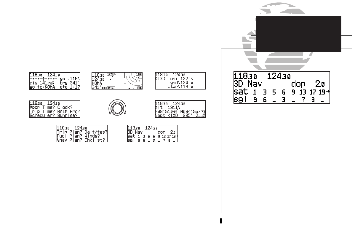
The GNC 250XL’s satellite status page provides satellite information to monitor
GPS coverage and receiver performance. This is helpful when you may be experiencing low signal levels due to poor coverage or installation problems.
To view the satellite status page:
1. Press Nand rotate Ountil the satellite status page appears.
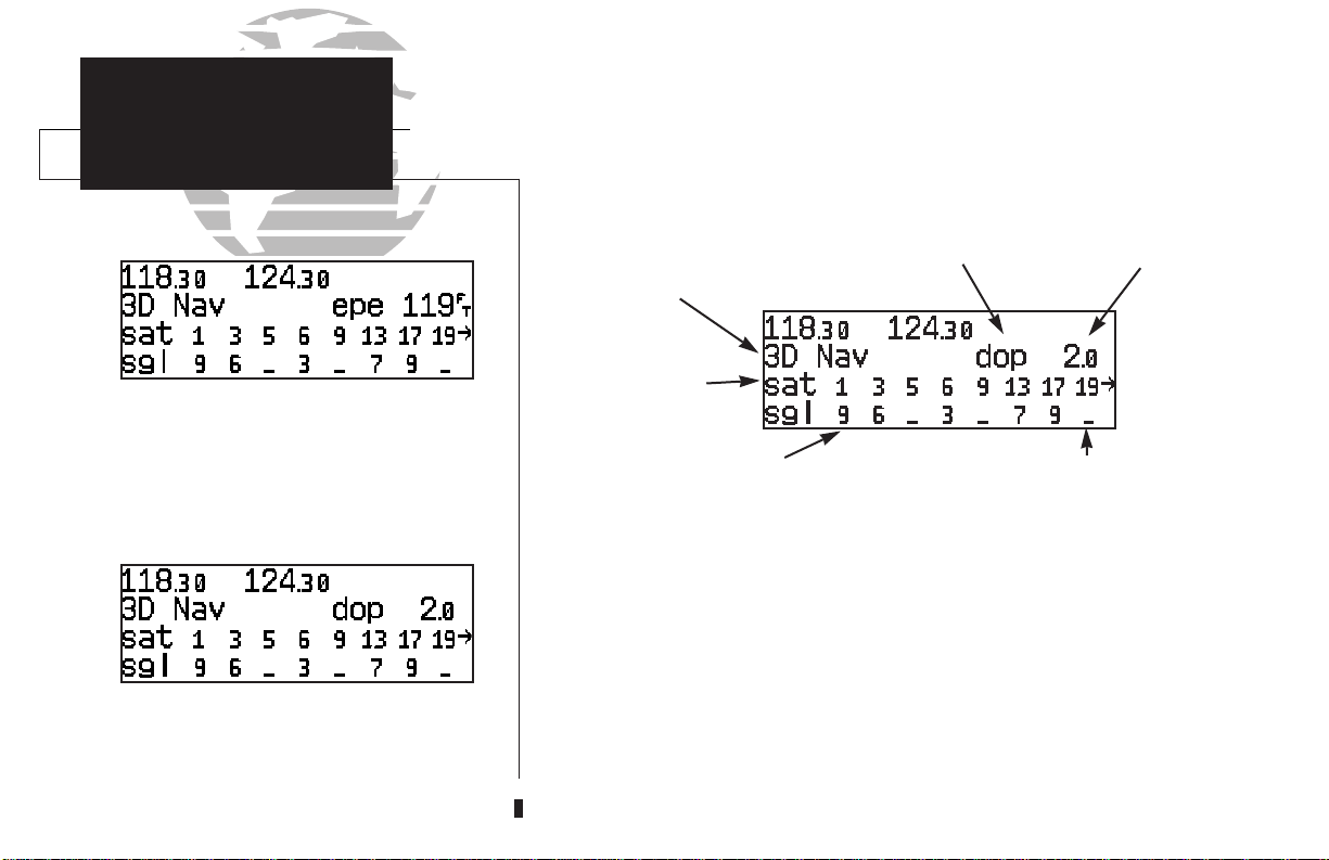
EPE/DOP
Receiver Status
Satellites in view
Satellite status page with ‘EPE’ displayed.
Estimated Position Error (EPE) gives an overall
measure of your position accuracy in feet or
meters.
The top line of the status page displays the receiver status and the current posi-
tion accuracy in DOP or EPE. The default setting is DOP.
The following functions may be displayed in the DOP/EPE field:
Satellite status page with ‘DOP’ displayed.
Dilution of Precision (DOP) measures relative
accuracy from 1 to 10.
20
Signal strength of
satellite being tracked (1-9)
• dop— Dilution of Precision, a measure of the satellite geometry quality
and relative accuracy of your position, with 1 indicating good
geometry and 10 indicating poor.
• epe— Estimated Position Error, an overall measure of your positional
accuracy in feet or meters using signal and data quality, receiver
tracking status and DOP.
Satellite in view
but not receiving signal
EPE/DOP
value
Page 31

To change the DOP/EPE field:
1. PressNand rotate Oto display the satellite status page.
2. If the desired field (EPE or DOP) is not displayed, press Ctwice.
3. Use Kto change between ‘epe’ and ‘dop’. Press Cto finish.
The receiver status field, located at the top left of the page, can display the following messages under various conditions:
Search Sky - The GNC 250XL is searching the sky for visible satellites.
You will be informed with the message ‘Searching the Sky’.
Acquiring - The GNC 250XL is acquiring satellites for navigation.
2D Nav - The GNC 250XL is in 2D navigation mode. If your installa-
tion does not include an altitude serializer, you must enter
the altitude manually (see page 2). ‘2D Dif Nav’ will appear
when you are receiving DGPS corrections in 2D mode.
3D Nav - The GNC 250XL is in 3D navigation mode and will compute
altitude. ‘3D Dif Nav’ will appear when you are receiving
DGPS corrections in 3D mode.
Simulator - The GNC 250XL is in simulator mode, which should only be
used for practice and trip planning. Never use simulator
mode for actual navigation.
Poor Cvrg - The GNC 250XL cannot acquire sufficient satellites for navi-
gation.
Need Alt - The GNC 250XL needs altitude in order to start/continue
navigation. Go to the position page and enter the altitude.
Not Usable - The GNC 250XL is unusable due to incorrect initialization or
abnormal satellite conditions. Turn the unit off and on again.
Autolocate - The GNC 250XL is looking for any satellite whose almanac
has been collected. This process can take up to five minutes.
NAV KEY
SECTION
Receiver
Status Field
‘Acquiring’ satellites for navigation. In this case,
the satellites are being received, but the data is
still being collected before a position can be
determined.
‘Searching the Sky’ for satellites. No satellite
almanac data exists in the GNC 250XL. It must
be recollected from the first available satellite.
1
21
Page 32

SECTION
1
NAV KEY
Satellite Data Page
The second and third lines of the satellite status page provide the satellite number
and signal strength of each satellite in view. The satellite status page shows signal
strength for up to eight satellites at a time. If additional satellites are being received
an arrow on the ‘sat’ line will indicate additional data is available.
To view additional satellites:
1. Rotate
K
to view more satellites.
Additional information regarding each satellite’s azimuth, elevation and other data
is also available.
To view individual satellite information:
Viewing individual satellite information.
elevation angle, rise or fall indication, User Range Accuracy (URA, or the range
measurement accuracy as determined by the satellite), azimuth and signal strength.
22
1. Press Nand use Oto display the satellite status page.
2. Press Ctwice to activate the cursor in the GPS window.
3. Use Oto highlight the satellite number you wish to view and press E.
This will display the satellite data page, showing the selected satellite’s number,
To view other satellites:
4. Rotate Kto view information for the next satellite.
5. Rotate Oand press Con the satellite status page when you are finished.
Page 33

In addition to the other five pages, the GNC 250XL features two menu pages to
perform a host of planning and navigation functions. NAV Menu 1 provides access to
the following functions:
• Trip Planning • Density altitude/true airspeed calc.
• Fuel Planning • Winds aloft calculations
• VNAV Planning • Checklists
To display NAV Menu 1:
1. Press N.
2. Rotate Ountil NAV Menu 1 is displayed.
Trip Plan is the first function listed on NAV Menu 1 and allows the pilot to view
distance, ESA, bearing and estimated time enroute (ETE) between any two waypoints,
and for programmed route legs. The ground speed can be varied manually to calculate several possible ETEs.
To use the trip planning function:
1. Press Nand rotate Ountil NAV Menu 1 is displayed.
2. Press Ctwice, then Eto access trip planning.
3. Rotate Kto select waypoint mode or desired route number and press E.
NAV KEY
NAV Menu 1
Trip Planning
NAV Menu 1
SECTION
1
4. For direct-to navigation, use
E
to accept the waypoints. To use your present position as a waypoint, leave the way-
point field blank.
5. For route calculations, choose either ‘cum’ for cumulative data (from beginning to end) or
the leg desired by rotating
6. Use
K
and Oto enter the ground speed. Press Eto calculate the values and
to finish.
K
and Oto enter the ‘to’ and ‘from’ waypoints. Press
K
.
C
Trip planning with values calculated between two
waypoints.
23
Page 34

SECTION
1
NAV KEY
Density Altitude &
True Airspeed
The density altitude/true airspeed function is also accessed from NAV Menu 1.
Density altitude is the theoretical altitude at which your aircraft will perform depending
on several environmental conditions, including air pressure and total air temperature
(the temperature including the heating effect of speed, read on a standard outside temperature gauge on most aircraft). True airspeed considers the same factors.
To calculate the density altitude and true air speed:
1. Press Nand rotate Ountil NAV Menu 1 is displayed.
2. Press Ctwice and rotate Oto highlight ‘Dalt/tas?’.
3. Press Eto access the density altitude page.
4. Use Kand Oto enter the indicated altitude (‘ialt’) and press E.
Density altitude/true airspeed page
required on the density altitude page, they will be used as the defaults.
Fuel planning page showing calculation from present position to ‘KDAL’.
24
tion and programmed routes. The fuel planning function requires the pilot to enter
the initial amount of fuel on board and the flow rate. You may also enter different
ground speeds to view various information based on different travel times. If your
installation is interfaced to a fuel flow sensor, the flow rate and other information will
be supplied by the fuel flow sensor.
5. Use Kand Oto enter the calibrated airspeed (‘cas’). Press E.
6. Use Kand Oto enter the air pressure (‘pres’) and press E.
7. Use Kand Oto enter the total air temperature (‘tat’).
8. Press Eand the density altitude and true airspeed will be calculated and displayed.
9. Press Cto remove the cursor.
If your installation includes components to provide any of the information
The fuel planning page will display fuel requirements for both direct-to naviga-
Page 35

To perform fuel planning operations:
1. Press Nand rotate Ountil NAV Menu 1 is displayed.
2. Press Ctwice and rotate Ountil ‘Fuel Plan?’ is highlighted. Press E.
3. Rotate Kto select either ‘wpt’ for direct navigation or the desired route number. Press E.
4. For waypoint-waypoint navigation, use Kand Oto enter the ‘to’ and ‘from’ waypoints.
Press
E
to accept the waypoints. To use the present position as a waypoint, leave the
corresponding waypoint field blank.
5. For route calculations, choose either ‘cum’ for cumulative route fuel requirements
(from beginning to end) or the leg desired by rotating
If leg is selected, it displays the amount of fuel required to fly until that leg is complete.
K
K
.
NAV KEY
NAV Menu 1
Fuel Planning
SECTION
1
For example: The fuel required to complete leg 2 is leg 1 + leg 2.
Fuel required to complete leg 4 is leg 1 + leg 2 + leg 3 + leg 4.
6. Rotate Oto advance the cursor to ‘fob:’ or ‘gs:’ (depending on which is displayed).
7. Use Kand Oto enter the fuel on board or the ground speed. Press E.
8. Rotate Oback two positions to highlight the ‘fob:’ or ‘gs:’ field again.
9. Rotate Kto display the other information. Press E.
10. Use Kand Oto enter the remaining data. Press E.
11. Use Kand Oto enter the flow rate, in units per hour, if needed. Press E.
The GNC 250XL will calculate the range and endurance (i.e., how long the fuel
will last) of your aircraft. These are found in the first field on the bottom row of the
page. The amount of fuel left on board (lfob) and reserve time after the selected
direct-to, leg or route is flown are displayed in the second field on the bottom row.
Fuel planning page showing calculations between
two waypoints.
Fuel planning page with other information
indicating ‘endurance’ and ‘reserve’ times.
25
Page 36

SECTION
1
NAV KEY
Winds Aloft &
VNAV Functions
The GNC 250XL’s winds aloft function is used to calculate the true direction and
speed of any winds, and indicates whether you are flying with a head wind or tail
wind, and the wind speed.
To calculate winds aloft:
1. Press Nand rotate Ountil NAV Menu 1 is displayed.
2. Press Ctwice and rotate Ountil ‘Winds?’ is highlighted. Press E.
3. Use Kand Oto enter your present heading in the ‘hdg:’ field. If your installation
includes a fuel/air data computer, this will be displayed automatically. Press
4. Use Kand Oto enter your true airspeed (TAS) in the ‘tas:’ field. If you have previously
calculated it using the density altitude/true air speed function, it will be displayed as the
default. Press
E
. The wind direction and speed and head/tail wind will be displayed.
E
.
Winds aloft page
Vertical navigation page
26
The VNAV function calculates vertical speed requirements to reach a desired altitude before
or after a specified distance from a waypoint. This is helpful when you’d like to descend to a certain altitude near an airport or climb to an altitude before reaching a route or direct-to waypoint.
To calculate vertical navigation parameters:
N
1. Press
2. Press
3. Use Kand Oto enter the initial (from) altitude. Your current GPS altitude will be displayed as the default. Press E.
4. Use Kand Oto enter the desired final (to) altitude. Press E.
5. Use Kand Oto enter the distance from the waypoint. Press E.
6. Use Kto select ‘before’ or ‘after’ the waypoint. Press E.
7. Use
or a direct-to waypoint). Press
and rotate Ountil NAV Menu 1 is displayed.
C
twice and rotate Ountil ‘Vnav Plan?’ is highlighted. Press
K
and Oto select the waypoint identifier (it must be a waypoint in the active route
E
.
E.
Page 37

You will now notice that the vertical speed has been calculated, based on your
present speed. If you desire a more rapid climb or descent rate:
8. Use Kand Oto enter the new desired vertical speed, or press E to accept the
calculated value.
9. Press
E
to activate the vertical navigation function.
If you enter a value greater than the value computed by the GNC 250XL, the time
before the maneuver is to begin will be displayed. When the countdown reaches 15 seconds, you will be informed with the message ‘Start altitude chng’. The VNAV function will
automatically be cancelled if the active direct-to or route is changed in any way, and you
will be informed with a ‘VNAV cancelled’ message.
The GNC 250XL allows you to create up to nine checklists with 30 items each to
remind you of repetitive tasks. These checklists can be called up at any time for review
and are useful for creating pre-flight checklists, landing checklists, emergency procedures, etc. Each name or function can have up to 16 characters each.
To create a checklist:
N
1. Press
2. Press
3. Press
Press
4. Use
and rotate Ountil NAV Menu 1 is displayed.
C
twice and rotate Ountil ‘Chklist?’ is highlighted. Press E.
C
and use Oto highlight the checklist you would like to create or edit.
E
.
K
and Oto enter the title of the checklist. Press
E.
NAV KEY
SECTION
NAV Menu 1
VNAV & Checklists
VNAV displayed on CDI page. The VNAV altitude
should be compared with the reading on the aircraft altimeter to ensure you are on the proper
climb/descent profile.
1
This will display the checklist items page. On this page you can enter each task,
such as ‘Check Fuel’.
5. Use Kand Oto enter the checklist item. Press E.
C
6. You may repeat step 5 to enter additional items, or press
to finish.
Checklist catalog page.
27
Page 38

SECTION
1
NAV KEY
Checklists
Approach Timer
To execute a checklist:
1. Press Nand rotate Ountil NAV Menu 1 is displayed.
C
2. Press
3. Use
4. Press
To delete a checklist item or an entire checklist:
twice and rotate Ountil ‘Chklist?’ is highlighted. Press E.
O
to highlight the checklist you would like to see. Press E.
E
to check off list items.
1. To delete a checklist item, highlight the desired item and press
2. To delete an entire checklist, highlight the desired list and press \, followed by E.
The GNC 250XL’s NAV Menu 2 provides access to various timer and planning func-
Executing a checklist.
NAV Menu 2
28
tions, including:
• Approach timer • Clock (Date and time)
• Trip Timer • RAIM Prediction
• Scheduler messages • Sunrise and sunset calculations
The approach timer acts as either a count up or a count down timer that can be
set or reset at any time.
To activate/change/view the approach timer:
N
1. Press
2. Press
3. Rotate
4. Use
5. Rotate
and rotate Ountil NAV Menu 2 is displayed.
C
twice and rotate Ountil ‘Appr Time?’ is highlighted. Press E.
K
to select either ‘Count up’ or ‘Count down’. Press E.
K
and Oto set the time from which to begin counting. Press E.
O
to select the desired function: ‘Start’, ‘Stop’, or ‘Reset’. Press Eto execute.
\
, followed by E.
Page 39

When the count down timer reaches zero, you will be informed with a ‘Timer
expired’ message. The timer will then begin to count up, displaying the time since it
expired. The timer runs, if not altered, whenever the GNC 250XL is turned on.
The GNC 250XL clock function keeps track of both UTC time (Greenwich Mean
Time or Zulu Time calculated from the satellites) and local time, allowing you to
designate which format to use for all time displays. The local time and date can be set
without displaying local time on other GNC 250XL pages.
To set the local date/time:
1. Press Nand rotate Ountil NAV Menu 2 is displayed.
2. Press Ctwice and rotate Ountil ‘Clock?’ is highlighted. Press E.
K
3. Use
4. Use
5. Use Kand Oto set the local time. Press E.
6. Press Cto complete.
The GNC 250XL’s trip timer will automatically keep track of the duration of your
current trip and can be configured to run either when the GNC 250XL is on, or when
your ground speed exceeds a specified value (see section 6).
To view or reset the trip timer:
1. Press Nand rotate Ountil NAV Menu 2 is displayed.
2. Press
to select either ‘utc’ or ’local’ time to be displayed in the time fields. Press E.
K
and Oto set the local date. Press E.
C
twice and rotate Ountil ‘Trip time?’ is highlighted. Press E. The current
time of day, departure time and time enroute will be displayed.
NAV KEY
SECTION
Clock Function
Trip Timer
Clock function set to display local time in the time
fields of all other GNC 250XL pages.
To reset the trip timer, highlight ‘Reset?’ and
press E.
1
3. To reset the timer, press
E
. To skip resetting the timer, press C.
29
Page 40

SECTION
NAV KEY
1
Enter the time and date for RAIM prediction.
RAIM available for the entered time, date and
waypoint location.
RAIM Prediction
The RAIM Prediction function allows you to confirm that GPS coverage is
available for a specific location or waypoint any day of the year. Receiver
Autonomous Integrity Monitoring performs checks to ensure that the GNC 250XL
will have adequate satellite geometry to work with during your flight. RAIM availability will be near 100% in Oceanic, En route and Terminal phases of flight.
To predict RAIM availability:
N
1. Press
2. Press Ctwice and rotate Oto highlight ‘RAIM Prd?’. Press E.
3. Rotate Oto highlight the field which you would like to change.
4. Use
position. Press
5. Use
you have selected from the clock display), and the day, month and year. The current date
will be displayed automatically. Press
6. Rotate Oto highlight ‘Compute RAIM?’.
7. Press Eto compute information.
When the computations are complete, the GNC 250XL will display whether or
not RAIM is available for the specified waypoint at the specified date and time. Refer
to the table on page 78 for specific RAIM protection limits as they relate to CDI scale
figures.
and rotate Ountil NAV Menu 2 is displayed.
K
and Oto enter the waypoint name, or leave it blank to use your current
E
to accept.
K
and Oto enter the ETA in hours and minutes (in local or UTC time, whichever
E
to accept.
30
Page 41

The scheduler function will display reminder messages (such as ‘Change oil’, ‘Switch
fuel tanks’, ‘Overhaul’, etc) after a specified time has elapsed. For example, if you enter
‘Change oil’ to be displayed in 30 hours, the message ‘Change oil’ will be displayed after the
GNC 250XL has been running in Normal mode for 30 hours. After appearing, the message
will be displayed each time the GNC250XL is turned on until it is changed or deleted.
To enter a scheduled message:
1. Press Nand rotate Oto display NAV Menu 2.
2. Press Ctwice and rotate Ountil ‘Scheduler?’ is highlighted.
3. Press E.
4. Rotate
O
to highlight the message you would like to edit. To delete, press \,
then
E
.
5. Use Kand Oto enter the message. Press E.
6. Use Kand Oto set the time to elapse before the message is displayed, in hours and
minutes, up to 99 hours and 59 minutes (this time is cumulative and counts whenever
the GNC 250XL is on in normal operating mode).
7. Press
E
.
You may edit another scheduled message by repeating steps 4, 5, 6 and 7, or if you
are finished, press C.
NAV KEY
SECTION
NAV Menu 2
Scheduler
The scrolling arrow prompt indicates which direction to scroll to view additional listings.
1
The scheduled message will appear after the timer
expires and reappear every time the GNC 250XL
is powered on until the message is changed.
31
Page 42

SECTION
1
NAV KEY
Sunrise/Sunset
Calculations
The GNC 250XL’s sunrise/sunset planning function allows you to calculate the time
of sunrise or sunset at any waypoint or your present position for a specified date.
To calculate sunrise and sunset times at a waypoint or at your present location:
1. Press Nand rotate Ountil NAV Menu 2 is displayed.
2. Press Ctwice and rotate Oto highlight ‘Sunrise?’. Press E.
3. Use Kand Oto enter the waypoint identifier, or leave blank to use current position.
Press
E
.
4. Press Eto accept the waypoint information.
5. Use Kand Oto enter the date desired.
Sunrise/sunset planning page showing UTC (Zulu)
sunrise and sunset times for ‘KROG’.
32
6. Press Eand the sunrise and sunset times will be calculated and displayed.
Page 43

Section 2
Communicating with the GNC 250XL
The GNC 250XL features a digital VHF radio that provides a seamless transition
from communication to navigation, bringing the two most important functions in flying together in one panel-mount unit. The GNC 250XL operates in the aviation voice
band, from 118.000 to 136.975 MHz, in 25 kHz steps.
Communication frequencies are selected by activating the cursor in the standby
frequency field and using the inner and outer knobs to dial in the desired frequency.
A frequency may also be quickly selected from the navigation database by simply
highlighting the frequency and pressing the Ekey. Once a desired frequency is displayed in the standby field, it may be made the active frequency by pressing the
key. Note that the active frequency may not by accessed directly. Whenever the cursor is
active in the comm window, the standby frequency will be highlighted.
To access the standby frequency, press C.
This allows you to change the megahertz (number to the left of the decimal) by
rotating Oand the kilohertz (number to the right of the decimal) by rotating K. If
you would like to keep the standby field ‘hot’ (ready for an immediate frequency
change), leave the cursor active in the comm window. To remove the cursor, press
C
twice after you have selected the desired frequency.
To make the standby frequency the active frequency, press @.
The frequencies will be flip-flopped and you’ll be able to transmit and receive on
the frequency previously entered as standby. This can be done at any time, regardless
of cursor or GPS status.
@
COMM FEATURES
SECTION
Overview
CDI page with cursor inactive.
CDI page with standby field active. To flip-flop the
frequencies, press
@.
2
33
Page 44

SECTION
COMM FEATURES
Overview
2
To auto-tune from the nearest airport page,
press E.
Auto-Tuning
During the course of navigating with the GNC 250XL, there may be times when
you need to quickly select a comm frequency while you are entering data in the GPS
window. Whenever data entry in the GPS window is interrupted by activating the
standby frequency field, the GPS field in use will become ‘splatted’, or blocked out.
Once the standby frequency has been entered, you may return to data entry by
pressing the Ckey. The cursor will return to the active GPS field at the point
where data entry was interrupted.
The GNC 250XL’s auto-tune feature allows you to quickly select any database
frequency in the GPS window as your standby frequency.
To select a frequency from a list, highlight the
desired frequency and press E.
34
To auto-tune a single frequency displayed in the GPS window:
1. Press Ewith the cursor inactive.
2. To make the standby frequency the active frequency, press @.
Page 45

To auto-tune a frequency from a list displayed in the GPS window:
1. Press Ctwice to activate the cursor in the GPS window.
2. Rotate Oto highlight the desired frequency.
3. Press Eto make the selected frequency the standby frequency.
Another useful feature integrating the GNC 250XL’s navigation and communication
capabilities is the Navigation Communications (NAVCOM) page, which is accessed
using the Nkey. See pages 16-17 for more on the NAVCOM page.
The GNC 250XL’s automatic squelch and volume controls are located at the
bottom left of the unit, near the NavData card slot.
COMM FEATURES
Auto-Tuning
Volume & Squelch
SECTION
2
To adjust the radio volume:
1. Rotate the Bknob.
Whenever the GNC 250XL is powered up, the automatic squelch will be in the
‘on’ position, allowing only transmissions which are powerful enough for clear broadcast to be received. Manual squelch control is not available.
To override the automatic squelch control:
1. Press the Qkey. Press Qagain to return to automatic squelch.
Whenever the GNC 250XL is transmitting, a ‘tx’ icon will appear between the
active and standby frequency fields. If the microphone is stuck or accidentally left in
the keyed position, or if the headsets continue to transmit after the key is released, the
radio will automatically timeout after 35 seconds of continuous broadcasting. You’ll
also receive a ‘Stuck mic/Tx disabled’ message as long as the stuck condition exists.
‘TX’ indicating radio transmission.
35
Page 46

SECTION
2
The emergency channel (121.50) will appear in
the active field by pressing @ for more than
two seconds.
COMM FEATURES
Emergency
Channel Selection
The GNC 250XL’s emergency channel select feature provides a quick method
of selecting the 121.5 MHz frequency as the active frequency in the event of an
in-flight emergency. The emergency channel select is available whenever the unit is
on, regardless of GPS or cursor status, or loss of the display.
To automatically tune for emergency transmission:
1. Press and hold the @key for more than two seconds.
36
Page 47

Section 3
Waypoint and Database Information
The GNC 250XL uses a Jeppesen NavData® card to provide position and facility
information for thousands of airports, VORs, NDBs and intersections. Each facility in the
database is stored as a waypoint with its own latitude/longitude, identifier (up to five letters and/or numbers), and other pertinent information. Up to 1,000 user waypoints may
also be created and stored in the GNC 250XL’s internal memory.
WPT KEY
Overview
SECTION
3
Waypoint Menu Page
Waypoints with Comments List
Waypoint information is available through four primary waypoint pages accessible
from the GNC 250XL’s Wkey. The waypoint pages may be scrolled through by pressing the Wkey and rotating the outer knob until the desired page is displayed, or by
pressing the Wkey repeatedly.
Proximity Waypoints Page
User Waypoint List
Please note that your GNC 250XL uses ICAO
identifiers for all airports. All U.S. airport identifiers
which contain only letters use the prefix ‘K’. For
example, Los Angeles International is KLAX under
the ICAO standard. Other airports, such as Otten
Memorial (3VS), that contain numbers in the
identifier, do not require the ‘K’ prefix. Many foreign
countries use two letter prefixes. For more
information on ICAO identifiers, contact:
Document Sales Unit
International Civil Aviation Organization
999 University Street
Montreal, Quebec
Canada H3C 5H7
37
Page 48

SECTION
3
WPT KEY
Waypoint Categories
& Menu Page
The GNC 250XL organizes waypoints into one of five waypoint categories for
your convenience. Each waypoint category provides different types of detailed information for a selected facility:
• Airports - Identifier, city/state, country, facility name, position (lat/lon),
elevation, runways, fuel services and communication frequencies.
• VORs - Identifier, city/state, country, facility name, position (lat/lon),
frequency, magnetic variation, co-located DME or TACAN and weather
broadcast indication.
• NDBs - Identifier, city/state, country, facility name, position (lat/lon),
frequency and weather broadcast indication.
The waypoint menu page allows you to select the
desired waypoint type (or category).
category from the waypoint menu page.
The airport position page shows the position,
field elevation and available fuels for the selected
airport.
38
• Intersections - Identifier, country, position (lat/lon), nearest VOR.
• User - Identifier (name), position (lat/lon), reference waypoint.
To view the waypoint information for a desired waypoint, select the waypoint
To choose a waypoint category (for viewing information):
1. Press Wand rotate Oto display the waypoint menu page. (If pressing Wonce
does not display the waypoint menu page, press
2. Press Ctwice and rotate Oto highlight the desired waypoint category.
3. Press
E
to accept the waypoint category. The waypoint identification or position page
for the selected category will appear with the waypoint identifier field ready for entry.
W
a second time.)
Page 49

After a waypoint category is selected, information for a waypoint may be viewed
by entering the identifier or name of the desired waypoint. Airports, VORs and NDBs
may be entered by either the identifier, name or the location (city) of the facility.
Intersections and user waypoints must be entered by the identifier.
To enter a waypoint identifier:
WPT KEY
Entering Waypoints
SECTION
3
1. With the cursor over the waypoint field, use
waypoint identifier.
As the identifier is entered, the GNC 250XL’s Spell’N’FindTMfeature will scroll
through the available database, displaying those waypoints matching the identifier letters you have entered to that point. When the desired waypoint is displayed, press
C
to remove the cursor.
To obtain waypoint information by entering the facility name of the airport or
navaid, or its location:
1. Press Wand rotate Oto display the waypoint menu page.
2. Press Ctwice and rotate Oto highlight the desired waypoint category.
3. Press Eto accept the waypoint category.
4. Rotate Oto highlight the middle field to enter location (city) OR:
Rotate Oto highlight the bottom field to enter facility name or VOR/NDB name.
5. Use Kand Oto enter the location or the name, and press Cto finish.
As the information is entered, the GNC 250XL will display any entries in its database that match the letters you have entered. If duplicate entries exist for the entered
identifier, name or location, additional entries may be viewed by rotating K. Once
the desired waypoint is displayed, press Cto continue.
K
and Oto enter the
Entering a waypoint by identifier.
Entering a waypoint by city. Note that punctuation marks are not used when entering locations
or names. Use spaces, where appropriate, to identify these marks. For example, St. Louis would be
entered as “ST LOUIS” without a period.
39
Page 50

SECTION
3
WPT KEY
Airport Information
Once a waypoint category and identifier have been selected, the GNC 250XL will
provide extensive information through a set of waypoint pages for the selected category. The pages available for each waypoint category are presented here in the order
they appear on the waypoint menu page: airports, VORs, NDBs, intersections and
user waypoints.
Airport Information
Airport Identification Page
Airport Comments Page
If the city or facility name information is too long
to fit the screen, the name will scroll across the
page every few seconds so the complete name can
be read.
Airport Runway Page
To scroll through the airport pages:
The airport position page shows the position,
field elevation and available fuel types for the
selected airport.
40
1. Make sure the cursor is not present. If it is, press C.
2. Rotate Oin either direction to scroll through the available pages.
Airport Communication Page
Airport Position Page
Page 51

The GNC 250XL features five airport pages:
airport identification— allows entry of desired airport by identifier,
facility name or city; displays region and/or country of facility.
airport position— allows entry of desired airport by identifier; displays
latitude, longitude and elevation; indicates usage and fuel availability;
displays available approaches and airport control/radar capability.
airport communication— allows entry of desired airport by identifier;
displays radio frequencies/usage, and sector and altitude restrictions.
airport runway— allows entry of desired airport by identifier; indicates
runway designations, length, surface and lighting information; displays
ILS/localizer and/or pilot-controlled lighting frequencies.
airport comments— allows entry of desired airport by identifier; displays
user comments for the selected airport.
Waypoint Type
and Identifier
Location
(city/state)
Region/Country
WPT KEY
SECTION
Airport Pages
Airport communication page. The down arrow
next to the identifier indicates additional frequencies may be displayed by rotating the K knob.
3
Facility Name
The airport identification page displays a selected airport’s identifier, region and
country, city/state and facility name. The identification page is always the first airport
page available, allowing you to quickly review an airport facility or select another
facility by entering the identifier, facility name or city of the desired airport.
{
Airport runway page. The down arrow next to
the identifier indicates additional runways may be
displayed by rotating the K knob.
41
Page 52

SECTION
WPT KEY
Airport
3
1 2 3
Position Page
4
Airport Position Page
The airport position page displays the latitude, longitude and elevation of the
selected airport, as well as usage or fuel availability, available approaches and airport
control/radar capability. The following descriptions and abbreviations are used on the
airport position page:
Elevation— In feet or meters
Usage/Fuel— If the airport is for military use, it will display ‘military’.
If it is private, the GNC 250XL will display ‘private’. If it is a
public airport, it will display the fuel type(s) available:
• av gas— 80-87 octane, 100 LL, 100-130 octane, or mogas is
available
• jet— Jet A, Jet A-1 or Jet A+ fuel is available
• av/jet— Both av gas and jet fuel are available
Position— In degrees/minutes or degrees/minutes/seconds of latitude
and longitude.
Approach Information— displays the airport approaches available
• no apr— No approach is available
65
• np-apr— Non-precision approach is available
• loc— Localizer approach is available
• ils— ILS approach is available
1. Identifier (selectable)
2. Elevation
3. Fuel Availability
4. Airport Position
5. Approach Information
6. Controlled Airspace/Radar Capability
42
Controlled Airspace Information— displays controlled airspace type
• class B • cta
• class C • tma
Radar— displays approach/departure radar capability
• radar— indicates radar is present
Page 53

The airport communication page displays the radio frequencies and usage for
the selected airport, as well as sector and altitude restrictions.
To view the communication page from any of the airport information pages:
1. Rotate Owith the cursor removed to display the communication page.
2. Rotate
K
in the direction of the arrow prompt to view additional frequencies. You may
also view additional frequencies with the cursor on the page by rotating the
The following descriptions and abbreviations are used on the communication page:
Frequencies without restriction information:
• ats - Automatic terminal information service (ATIS)
• ptx - Pre-taxi
• clr - Clearance delivery
• gnd - Ground
• twr - Tower
• uni - Unicom
• mul - Multicom
• atf - Aerodrome traffic frequency
• ctf - Common traffic advisory frequency (CTAF)
• mf - Mandatory frequency
• oth - Other frequencies
Frequencies with restriction information:
• dep - Departure • apr - Approach
• arv - Arrival • class B
• cta - ICAO control area • tma - ICAO terminal control area
• class C • trsa - Terminal radar service area
O
knob.
WPT KEY
SECTION
Airport
Communications Page
Airport communications page for KCLT. Note
the ‘rx’ (receive only) indication on the ATIS
frequencies.
3
‘Receive only’ frequencies will be followed by an ‘rx’ indicator, while ‘transmit
only’ frequencies will display a ‘tx’. If a frequency has sector and/or altitude restrictions, they will also be displayed. Sector restrictions define a range of radials from the
facility, while altitude restrictions may describe an area above, below or between
altitudes. Additional instructions, if available, will be displayed on the bottom line.
Frequency page with sector restrictions.
43
Page 54

SECTION
3
WPT KEY
Airport
Runway Page
The airport runway page displays runway designations, length, surface and
lighting for the selected airport, as well as ILS/localizer and/or pilot-controlled lighting frequencies.
To view the runway page from any of the airport information pages:
1. Rotate Owith the cursor removed to display the runway page.
2. To view additional runway information, rotate
The scrolling arrow prompt, located beside the identifier field, indicates which direction to
scroll for additional runway information.
If a localizer and/or ILS are used on the same runway, rotating Kwill sequence
through both sets of information.
Airport runway page for KICT.
To view additional runways, rotate the K knob in
the direction of the arrow prompts.
44
The following descriptions and abbreviations are used on the airport runway
page:
Runway surfaces:
• hard - Hard (concrete, asphalt, etc.) • turf - Turf (grass)
• seal - Sealed surface • grav - Gravel surface
• dirt - Dirt surface • soft - Unknown soft surface
• unkn -Unknown surface • watr - Water landing site
Runway lighting:
• pt lights - Part-time lights
• ft lights - Full-time lights
• pc - Pilot-controlled (with frequency) lights
• no lights - No runway lighting
K
with the cursor removed.
Page 55

VOR Information
The GNC 250XL features three VOR waypoint pages:
VOR identification— allows entry of desired VOR by identifier,
facility name or city; displays region and/or country of facility.
VOR position— allows entry of desired VOR by identifier; displays
latitude, longitude and frequency; provides magnetic variation, weather
broadcasts and DME/TACAN information.
VOR comments— allows entry of desired VOR by identifier; displays user
comments for the selected facility.
WPT KEY
VOR Information
SECTION
3
VOR information is accessed by entering the desired facility by identifier, city or
facility name (see page 39) on a VOR waypoint page. The VOR identification and
comments pages are identical in form and function to their airport page counterparts.
To scroll through the VOR pages:
1. Make sure the cursor is not present. If it is, press C.
2. Rotate Oin either direction to scroll through the available pages.
In addition to displaying the VOR frequency, magnetic variation and position, the
VOR position page indicates if a DME or TACAN is co-located at the facility. The ‘wx
bdcst’ field indicates that the VOR also transmits weather information.
VOR identification page
VOR position page showing co-located TACAN
facility and weather broadcast.
45
Page 56

SECTION
3
NDB Information
WPT KEY
NDB Information
NDB Position Page
The GNC 250XL also uses identification, position and comments pages for NDB
information. The NDB waypoint pages are used in the same manner as VOR pages:
NDB information is accessed by entering the desired facility’s identifier, city or name
(see page 39) on the NDB identification page.
NDB identification page
To scroll through the NDB pages:
1. Make sure the cursor is not present. If it is, press C.
2. Rotate Oin either direction to scroll through the available pages.
The NDB position page (see above) displays the selected facility’s identifier, frequency and position, as well as any weather broadcasts available. The NDB comment
page will display any user comments for the selected NDB (see page 54 for instructions on entering user comments).
NDB comments page
46
Page 57

Intersection Information
Intersection Position Page
The last database waypoint category available is intersections. Two intersection
pages are available: intersection position and intersection comments. Intersections
may be entered by identifier only (not city or name) on either intersection page.
WPT KEY
Intersection
Information
SECTION
3
To scroll through the intersection pages:
1. Make sure the cursor is not present. If it is, press C.
2. Rotate Oto toggle between the available pages.
The intersection position page displays the selected facility’s identifier, region and/or
country, latitude and longitude, and the identifier, distance and bearing to the nearest
VOR (not necessarily the VOR used to define the intersection). The intersection comment page will display any user comments for the selected intersection (see page 54).
Intersection comments page
47
Page 58

SECTION
3
WPT KEY
User Waypoints
User Waypoint Information
In addition to the airport, VOR, NDB and intersection waypoints contained in your
NavData® card, the GNC 250XL allows you to store up to 1,000 user-defined waypoints. Once a user waypoint is created, two user waypoint pages will display the following information:
• Waypoint identifier
• Position in latitude and longitude
• Identifier, range and bearing from a reference waypoint
• User comments
User waypoint page
User waypoint comments page
48
To scroll between the user waypoint position page and the user comments page,
rotate O. User waypoints may be created or modified using the Wkey. After select-
ing the waypoint identifier, as shown on page 39, you will be prompted to enter information if the waypoint is new. There are three ways to create a user waypoint’s position from the Wkey:
1. Enter the exact position of the new waypoint.
2. Reference a known waypoint by range and bearing.
3. Enter a range and bearing from your current position.
To create or edit a user waypoint:
1. Press W.
2. Press Ctwice and use Oto highlight the ‘user?’ field. Press E.
3. Use Kand Oto enter the waypoint identifier. Press E.
Page 59

If the waypoint identifier entered does not exist, you will be prompted to select a
method to enter the new waypoint’s position into memory. If the waypoint exists (i.e.,
you’re just reviewing or editing a user waypoint), skip step 4 and move on to the next
set of instructions.
4. Select the desired waypoint entry method using Oand press E.
You will automatically be placed on the latitude and longitude field (if you
selected ‘enter posn?’), the ‘from’ field (if you select ‘ref wpt?’) or the ‘bearing’ field (if
you select ‘rng/brg from posn?’).
To enter/edit the position of the user waypoint:
1. Use
K
and Oto enter the latitude. You may select either north or south and enter a
latitude up to (but not including) 90°.
2. Press
E
.
3. Use
K
and Oto enter the longitude. You may select either east or west and enter a
longitude up to (but not including) 180°.
4. Press
E
.
Once the latitude and longitude have been entered, the cursor will move to the
reference waypoint field,where you may enter a reference waypoint to calculate a
bearing and distance to the new waypoint position. If you are not entering a reference
waypoint:
WPT KEY
SECTION
Creating
User Waypoints
Selecting a method to enter a new user waypoint.
3
5. Press Eto advance the cursor to the ‘ok?’ prompt and press Eto save the new
waypoint in internal memory.
Entering the user waypoint’s exact position.
49
Page 60

SECTION
3
WPT KEY
Reference Waypoints
To enter/edit a user waypoint position from a reference waypoint:
K
1. Use
2. Press E. The waypoint’s position will appear.
3. Use Kand Oto enter the bearing from the reference waypoint.
4. Press E.
5. Use Kand Oto enter the distance from the reference waypoint.
6. Press E. The latitude and longitude will be calculated for the waypoint.
7. Press Eto confirm the ‘ok?’ prompt and save the waypoint position.
and Oto enter the reference waypoint’s identifier.
Entering a user waypoint by referencing another
waypoint.
To create a user waypoint from your present position, leave the reference waypoint field blank and
enter a bearing and distance from your present
position. The GNC 250XL will calculate the new
50
waypoint’s coordinates automatically.
If you have chosen to create a waypoint at a certain bearing and distance from
your current position, your current position will be displayed and you will enter the
bearing and distance at which you would like the new waypoint to be located.
To create a user waypoint offset from your present position:
1. Use Kand Oto enter the bearing from your position.
2. Press E.
3. Use Kand Oto enter the distance from your position.
4. Press E. The latitude and longitude will be calculated for the new waypoint.
5. Press Eto confirm the ‘ok?’ prompt and save the waypoint position.
Page 61

The GNC 250XL’s AutoStoreTMfunction provides another method of creating
user waypoints. AutoStore is used to instantly capture your present position as a user
waypoint with a touch of a button and add the new waypoint to the end of a specified
route if desired.
To perform an AutoStore:
1. Press Nand rotate Oto display the position page or map page.
2. Press E.
This will display the ‘Save waypoint’ screen, which will allow you to rename the
waypoint and choose the route to which it should be added. The GNC 250XL will
assign the next available three-digit number as the default waypoint name, preceded
by a ‘+’ sign. This will help you differentiate AutoStore waypoints from other user
waypoints.
To change the default name or route of an AutoStore waypoint:
1. Rotate Oto select the name or route number field.
2. Use
K
and Oto enter the name or route number. If you do not want to add the way-
point to a route, be sure to keep the route field blank.
3. Press
E
to accept.
4. Press Eto confirm the ‘ok?’ prompt.
WPT KEY
SECTION
Creating Waypoints
with AutoStore
AutoStore waypoint with default name.
3
If the waypoint name you entered is already assigned to another waypoint, you
will be informed with the message ‘WPT exists ______’. The default waypoint name
will be redisplayed, and you may enter a different name.
The default waypoint name may be changed
before saving the waypoint.
51
Page 62

The second page available from the GNC 250XL’s Wkey is the proximity
SECTION
WPT KEY
3
Proximity alarm message. Pressing N will
display the position page with the bearing and
distance from the proximity waypoint indicated
on the bottom line.
52
Proximity Waypoints
Proximity waypoints page
waypoints page. This page allows you to define an alarm circle around a selected
waypoint and is useful in defining alarm circles around towers or obstructions. Up to
nine proximity waypoints can be entered, each with an alarm radius of up to 99.9 nm.
To create or edit a proximity waypoint:
1. Press Wand use Oto display the ‘Proximity waypoints’ page.
2. Press Ctwice and use Oto highlight the first available field.
3. Use
K
and Oto enter the identifier. It may be an airport, VOR, NDB, intersection or user
waypoint. Press
4. Use Kand Oto enter the radius of the alarm circle. Press E.
If two proximity waypoints are entered and their regions overlap, you will be
informed with the message ‘Proximity overlap’. This message will be displayed each
time you turn on the GNC 250XL for as long as the overlap remains. Warning: If you
enter the overlap area you will only be informed of the nearest proximity waypoint.
To remove a waypoint from the proximity waypoints page:
1. Press Ctwice, if necessary, to obtain a cursor in the GPS window.
2. Press \to erase the name, and then Eto delete.
To scroll through the proximity waypoints list:
1. Rotate
available proximity waypoints. The scrolling arrow prompt will indicate the direction to
scroll to view additional waypoints, if available.
E
.
K
with the cursor inactive (or use Owith the cursor active) to scroll through the
Page 63

The third page available from the GNC 250XL’s Wkey is the user waypoint
list, which can be used to quickly scan, review, rename or delete user waypoints.
To display the user waypoint list:
1. Press Wand use Oto display the user waypoint list.
2. To scroll through the list, rotate K.
The total number of user waypoints is displayed at the top of the page, with the
individual user waypoints listed two at a time in alphabetical order below. The
scrolling arrow prompt, located at the top left of the page, will indicate which direction to scroll to view additional waypoints. The status of each waypoint will be displayed to the right of the identifier when it is the active-to waypoint, part of an active
or stored route or a proximity waypoint. To edit, rename or delete waypoints, the cursor must highlight the desired waypoint.
To highlight a waypoint:
1. Press Ctwice and use Oto highlight the desired waypoint.
To edit a highlighted waypoint’s position:
1. Press
E
to obtain the waypoint position page. Edit the waypoint position as described on
page 49. (Note: The active-to waypoint cannot be edited.)
To delete a waypoint from the list:
WPT KEY
SECTION
User Waypoint
List
User waypoint list showing the current active-to
waypoint and a proximity waypoint.
3
1. Highlight the desired waypoint and press
To rename a waypoint from the list:
1. Highlight the desired waypoint. Use
identifier for the waypoint.
2. Press
E
on the confirmation page to change the name, or press \to cancel.
\
. Press Eto confirm the deletion.
K
and Oto enter a new
Renaming a user waypoint.
53
Page 64

SECTION
3
WPT KEY
Waypoint Comments
The last page available through the GNC 250XL’s Wkey is the waypoints with
comments page, which lists all waypoints that have a user comment. User com-
ments may be added to 250 waypoints stored in the user or NavData®database, and
allow you to note two lines of special information concerning a particular waypoint.
To enter user comments:
1. Enter the waypoint identifier from any waypoint page (see page 39), and press
remove the cursor.
2. Rotate
O
to display the ‘comments’ page.
3. Press Ctwice and use Oto highlight either the second or third line.
4. Use Kand Oto enter the comment.
Entering waypoint comments.
up to six waypoints at a time. The scrolling arrow prompt will indicate which direction to scroll to view additional waypoints.
Waypoints with comments page
54
5. Press
E
to accept, and repeat steps 4 and 5, if necessary, to enter information on the
other line.
6. Press
C
to remove the cursor.
To view the ‘waypoints with comments’ list:
1. Press Wand use Oto display the ‘Wpts with comments’ page.
2. Use Kto scroll through the list.
The GNC 250XL will display the waypoints with comments in alphabetical order,
To view comments for a selected waypoint:
1. Highlight the desired waypoint and press E(or press \and Eto delete).
2. Rotate Oto display any other available pages for the selected waypoint.
C
to
Page 65

The GNC 250XL’s extensive waypoint database makes it possible for several way-
points to share the same identifier. To ensure that you are selecting the waypoint
desired, the GNC 250XL will always offer the waypoint confirmation page (which
shows the waypoint’s position) when an identifier is entered for a particular function.
To accept the waypoint position:
1. Press Ewith the cursor over the ‘ok?’ prompt.
To reject the waypoint position:
1. Press
\
with the cursor over the ‘ok?’ prompt.
Once a waypoint has been accepted or rejected, the previous page will be displayed. If there is more than one waypoint available for a selected identifier, the GNC
250XL will display a duplicate waypoint page for you to choose the desired waypoint.
The waypoint identifier and number of duplicates will be shown at the top of the
page, with the waypoint type and region of each duplicate indicated below. The waypoints listed are sorted by the distance from your present position.
To scroll through additional duplicate waypoints:
1. Rotate Owith the cursor active, or Kwith the cursor inactive.
To select the desired waypoint from the duplicates list:
O
1. Activate the cursor and rotate
2. Press E. The waypoint confirmation page will appear.
3. Press
E
over the ‘ok?’ prompt to accept the waypoint or \to reject the waypoint
and return to the duplicate waypoints list.
to highlight the desired waypoint.
WPT KEY
Waypoint Confirmation
Duplicate Waypoints
Waypoint confirmation page
Duplicate waypoints page
SECTION
3
55
Page 66

SECTION
3
WPT KEY
Locked Waypoints
Waypoint Scanning
Because the GNC 250XL relies on a NavData card for most waypoint information,
there may be instances when waypoint information is not available for use. Locked
waypoints exist when a waypoint contained in a route, used as a proximity waypoint
or with a comment is not contained on the NavData card, or no card is inserted in
the unit. If this condition exists, you’ll be alerted with a ‘Proximity wpt locked’,
‘Route wpt locked’ or ‘Wpt comment locked’ message when the unit is powered up.
The identifier of a locked waypoint will be replaced with a ‘lockd’ message, which
indicates you cannot obtain waypoint information or navigate to the waypoint. The
identifier of a locked waypoint may be displayed by highlighting ‘lockd’ and pressing
E
. Locked waypoints may be deleted from routes, the proximity waypoints list or
waypoints with comments page by following the instructions in the appropriate
section of this manual.
Possible messages for locked waypoints.
To blank a waypoint field, highlight the field and
press the \ key.
56
The waypoint scanning feature provides a fast way to scan through airports,
VORs, NDBs and intersections in the database by identifier, facility name or city.
Waypoint scanning may be used from any blank identifier field in the GPS window.
To enter a waypoint by scanning the identifier, facility name or city:
1. With the cursor over a blank identifier field, press W. If the identifier field is not blank,
highlight the field with the cursor and press \before pressing W.
2. Use Oto highlight the waypoint category you wish to scan.
3. Press Eto activate the scanning mode.
4. Rotate Oto place the cursor over the field you want to scan (identifier, facility or city
name).
5. Use Kand Oto enter the letters of the identifier, city or facility name. The GNC 250XL
will scan the database and display the first waypoint that matches your entry.
6. Press Eto accept the waypoint, and Eagain to confirm the waypoint for the
function being used.
Page 67

Section 4
Nearest Waypoints
The GNC 250XL’s Tkey provides detailed information on the nine nearest airports,
VORs, NDBs, intersections and user waypoints within 200 nm of your current position.
In addition, it will display the two nearest Flight Service Station (FSS) and center
(ARTCC/FIR) points of communication, plus alert you to any Special Use Airspace (SUA)
you may be in or near. The Tkey can be used in conjunction with the GNC 250XL’s
direct-to function to quickly set a course to a nearby facility in case of an in-flight emergency.
To view the nearest waypoint information:
1. Press
T
.
This will display the nearest airport to your present position, subject to the runway
surface type and minimum runway length selected (see page 79).
To scroll through the next eight nearest airports, rotate K.
You may examine both the communication frequencies and the runway information
directly from the nearest airport page. You may also place the displayed frequency into
the standby field by pressing Efrom the nearest airport page.
To view more comm/runway information:
1. Press Ctwice and rotate Oto highlight the comm field or the runway field.
K
2. Rotate
To perform a direct-to on any of the nearest waypoint pages:
1. Press
2. Press
to scroll through more information, if available.
D
. The waypoint confirmation page will appear.
E
to accept the waypoint or \to cancel.
Nearest airport with other frequency information.
If an airport has multiple frequencies available,
they may be quickly viewed without activating
the cursor by pressing the \ key repeatedly.
Nearest FSS page. To view additional frequencies
(if available), highlight the frequency and rotate
the O knob.
NRST KEY
Overview
SECTION
4
57
Page 68

The nearest waypoints for other categories (VORs, NDBs, etc.) may be viewed
SECTION
NRST KEY
Special
4
Nearest SUA with controlling agency displayed.
NOTE: The GNC 250XL will flash the Unext to the Mkey
to inform you of SUA alerts. You do not have to repeatedly
check the Nearest Waypoint page for SUA information. It is
provided to supply more information on the SUA and its
boundaries. The GNC 250XL will not flash alerts, however, if
it has been turned off or if your altitude is such that you will
not enter the buffered airspace. Turning off SUA alerts and
58
setting the altitude buffer is described on page 84.
Use Airspace
Nearest SUA
by rotating O. Rotating Ocontinuously to the left will stop page selection on the
nearest airport category.
The next page available under the GNC 250XL’s Tkey is the SUA (special-use
airspace) alert page. The SUA alert page will alert you to as many as nine controlled or
restricted airspaces near or in your flight path, according to the following conditions:
• If your projected course will take you inside an SUA within the next 10
minutes, the message ‘SUA ahead < 10 min’ will be displayed.
• If you are within two nautical miles of an SUA and your current course will take
you inside, the message ‘SUA Near & Ahead’ will be displayed.
• If you are within two nautical miles of an SUA and your current course will not
take you inside, the message ‘Near SUA < 2nm’ will be displayed.
• If you have entered an SUA, the message ‘Inside SUA’ will be displayed.
Note that the GNC 250XL’s SUA alerts are based on three-dimensional data (latitude,
longitude and altitude) to avoid nuisance alerts. The alert boundaries for controlled airspace are also sectorized to provide complete information on any nearby airspace. Once
you have met one of the described conditions, the message annunciator will flash, alerting you of an SUA message.
To view an SUA message:
1. Press the Mkey.
2. Press Magain to return to the previous page.
Once you are notified of a SUA alert, detailed information concerning the specific
SUA is provided by the Tkey.
Page 69

To view the SUA alert page:
1. Press the
2. Rotate
The SUA alert page contains the following information:
T
key.
O
one stop to the right to view the SUA alert page.
NRST KEY
Special
Use Airspace
SECTION
4
SUA number
SUA Name or
controlling
agency
Controlling
airport identifier
The ‘SUA number’ field displays which SUA you are viewing (you may be alerted to up
to nine SUAs). SUAs are ranked with ‘sua1’ being the highest priority, and ‘sua9’ being the
lowest priority from your current position. The ‘SUA alert’ field displays the corresponding
alert message for this SUA, such as ‘near’, ‘near & ahead’, etc. (see page 58). The ETE (estimated time enroute), located at the top right of the page, will only be displayed if you are
projected to enter the airspace.
The second line of the SUA alert page displays the name or controlling agency of the
SUA, along with the type of SUA to which you are being alerted.
To toggle between the SUA name and controlling agency display:
1. Rotate Kone stop in either direction.
If the SUA name or controlling agency is too long to fit on the display, the GNC 250XL
will automatically scroll to display the rest of the information.
SUA Ceiling altitude
Alert type
SUA Floor altitude
ETE
(if applicable)
SUA type
59
Page 70

The following SUA types can appear in the SUA type field:
SECTION
NRST KEY
4
Frequency information for SUA. If the information is too long to fit on the display, the GNC
250XL will automatically scroll to display the rest
of the information.
60
SUA Messages
SUA alert page
and the ceiling and floor altitudes for the SUA alert. Controlling agency frequencies
may be viewed by highlighting the controlling airport identifier with the cursor and
pressing E. The following are examples of what can appear in the altitude fields:
Message Airspace Type
alrt - Alert
caut - Caution
cl B - Class B
cl C - Class C
cta - ICAO Control Area
dngr - Danger
moa - Military Operations Area
proh - Prohibited
rstc - Restricted
tma - ICAO Terminal Control Area
trng - Training
trsa - Terminal Radar Service Area
unsp - Unspecified
warn - Warning
The last line on the SUA alert page displays the SUA’s controlling airport identifier
Message Meaning
8000ftM - 8000 feet mean sea level (MSL)
3000ftA - 3000 feet above ground level (AGL)
ground - Ground level
msl - Mean sea level
notam - See Notice to Airmen (NOTAM)
for altitude restrictions
not sp - Altitude is not specified
unlmtd - Altitude is unlimited
Page 71

SUA Settings Page
All SUA alert messages except for prohibited areas may be turned on or off
through the GNC 250XL’s unit settings options, found under the Mkey (see page
84). Alerts for prohibited areas will always be displayed, regardless of unit settings or
operating mode. SUA alerts may be turned off so the pilot can avoid continuous alerts
in areas with extensive special use airspace.
NRST KEY
Special Use
Airspace
SECTION
4
Important: Turning off the SUA alerts only stops the display of SUA messages.
Any applicable SUA alert pages will still be available from the Tkey.
The GNC 250XL also features an altitude buffer which may be set to provide a
greater level of protection from penetrating an SUA. By specifying an altitude in the
buffer, you can effectively stretch an SUA’s altitude boundaries in both directions. This
allows the pilot to add an extra margin of prevention around controlled or restricted
airspace. For instructions on setting the altitude buffer, see page 84.
Altitude buffer set at 500 feet. This provides an
added 500 foot margin beyond the floor and ceiling limits for an airspace.
61
Page 72

SECTION
ACTIVE LEG
EOS
KTUL
SGF
KSTL
'ACTIVE FROM' WAYPOINT
'ACTIVE TO' WAYPOINT
MAP
5
ROUTE TERMINOLOGY
The diagram at the right shows a basic route
consisting of five waypoints and four legs.
The waypoint you are travelling to is called the
‘active to’ waypoint, and the waypoint immediately
behind you is called the ‘active from’ waypoint. The
course line between the active from and the active to
waypoint is called the ‘active leg’.
DIRECT-TO
& ROUTE NAV
Section 5
Direct-to & Route Navigation
One of the many benefits of GPS navigation is the ability to fly directly to a waypoint or fly a chain of waypoints without using ground-based navigation aids. To take
advantage of the convenience and efficiency provided by point-to-point GPS navigation, the GNC 250XL provides two basic methods of selecting a destination for your
flight: direct-to and route navigation. The direct-to function provides a fast way to
set a course to a destination waypoint from your present position. The route function
allows the pilot to create a chain of waypoints to fly in sequence.
62
As you pass each waypoint in the route, the GNC 250XL’s automatic leg sequencing and turn anticipation features will automatically select the next waypoint as the
‘active to’ waypoint and provide smooth steering guidance around the turn. If you are
not currently navigating a particular route leg (e.g., your starting position is not a
route waypoint), the GPS will select the appropriate leg as the active route segment.
Page 73

The GNC 250XL’s direct-to function provides a quick method of setting a course
to a destination waypoint. Once a direct-to destination is activated, the GNC 250XL
will establish a point-to-point route line along the great circle from your present
position to the destination and provide steering guidance and navigation data to the
waypoint until it is cancelled. If you are navigating to a waypoint and get off course,
the direct-to function may also be used to re-center the d-bar to proceed to the same
waypoint.
To select a direct-to destination:
D
1. Press the
2. Use
K
3. Press
To re-center the d-bar to the same active-to waypoint:
1. Press the
A direct-to may also be quickly activated from many pages that display a single
waypoint identifier (e.g., the nearest airport page) by simply pressing Dand E.
For pages that display a list of waypoints (e.g., the user waypoint list page), you must
highlight the desired waypoint with the cursor before pressing the Dkey. Once a
direct-to is activated, the GNC 250XL will provide navigation guidance until the
direct-to is cancelled or the unit is turned off.
To cancel a direct-to destination:
key. The CDI page will appear with the destination field highlighted.
and Oto enter the identifier of the desired waypoint.
E
to confirm the identifier, and Eto accept the direct-to confirmation page.
D
key, followed by Etwice.
DIRECT-TO
SECTION
Selecting and
Cancelling a Direct-To
To select a direct-to destination, press the D key
and enter the waypoint identifier using K and O.
5
1. Place the cursor over the destination field on the CDI page.
2. Press
\
. The destination field will go blank.
3. Press
E
. The GNC 250XL will resume navigating route 0 (the active route) if available.
To quickly select a direct-to from any page that
displays a single waypoint identifier (e.g., the
nearest airport page), press D, followed by E.
63
Page 74

SECTION
5
DIRECT-TO
Manually Selecting
A Course
Whenever you perform a direct-to, the GNC 250XL will set a point-to-point great
circle course to your destination. You can also manually define the course to your
destination with the GNC 250XL’s course select feature. The course select feature is
available from the bottom line of the direct-to confirmation page and works like
selecting your desired course on a VOR indicator.
Waypoint Position, Facility
Name or City/Region
(selectable)
Waypoint Identifier Field
The waypoint sequencing field, located at the
bottom left of the direct-to confirmation page,
allows you to ‘hold’ on a selected route waypoint
and prevent the GNC 250XL from sequencing to
the next route waypoint.
If you have selected the ‘hold’ setting from the
waypoint sequencing field, your selected course
will appear at the bottom left of the CDI page and
the map page. You may change your selected
course right from this field by highlighting the
course field and rotating the inner knob. Press E
to confirm the course.
64
Waypoint
Sequencing Field
To manually set a course:
D
1. Press the
2. Rotate
3. Use
K
you have started editing the course select field).
4. Press Eto accept the course, and Eagain to acknowledge the ‘ok?’ prompt.
The GNC 250XL will now use the selected course for your CDI and DTK steering
guidance. To reset the course to a GPS-calculated course from your present position,
simply press D, followed by E.
key. The direct-to confirmation page will appear.
O
to place the cursor on the course select field.
to begin entry of the selected course (the Oand Kknobs may be used once
Course Select Field
Page 75

The GNC 250XL lets you create up to 20 routes (numbered 0 through 19), with
up to 31 waypoints each. Routes are created, copied and edited through the Rkey,
which features two route pages selectable from the GNC 250XL’s outer knob: the
active route page and the route catalog page. The active route page provides infor-
mation and editing functions for route 0, which always serves as the route you are
currently navigating. The route catalog page serves as the main page for creating, editing, activating, deleting and copying all routes.
Routes 1-19 are used as storage routes, which are stored in the GNC 250XL’s internal memory. Once a storage route is ‘activated’, it is placed into route 0 for navigation
until it is cancelled, overwritten by activating another route or erased when the GPS is
turned off. If you want to save a route currently in route 0, be sure to copy it to an
open storage route (routes 1-19) before it is cancelled, overwritten or erased.
The GNC 250XL’s route catalog page is used to create, edit, delete or copy
routes, and serves as the main page for a host of functions. These include route activation, determining the closest point of approach and search and rescue operations. It
also displays a summary of routes currently stored in memory, with the departure and
arrival route waypoints and total distance for the selected route number. To scroll
through the available routes, rotate K. A one-line user comment may be added to
any storage route, which will be displayed on the route catalog page.
ROUTES
Overview
Route Catalog Page
21
3
Route Catalog Page
5
SECTION
5
{
4
To add user comments to any route (except route 0):
1. Rotate Kto display the route you would like to add comments to.
2. Press Ctwice and use Oto highlight the bottom row.
3. Use Kand Oto enter comments, and press E. To erase press \, then E.
1. Route selection field
2. Route action field
3. Departure/Arrival waypoints
4. Cumulative distance of route
5. Comments/Parallel track offset field
65
Page 76

SECTION
5
ROUTES
Creating &
Editing Routes
Selecting the route edit function.
The route action field, located at the top right of the page, is used to select the
desired route operation. The following functions are available:
• Activate - activate the route for navigation
• Reverse - activate a route in reverse order
• Edit - create a new route, or edit an existing route
• Delete - delete a route
• Copy - copy the current route to an empty route
• CPA - calculate the closest point of approach
• Search - perform search and rescue ladder operations
The route editing function allows you to create new routes and edit existing routes.
Creating routes before takeoff can help make route operations faster and easier during
your flight.
To create or edit a route from the route catalog page:
1. Use Kto display the route number you would like to edit.
2. Press Ctwice.
3. Use Kto select ‘edit?’. Press E. The route review page will appear.
To add a waypoint:
4. Rotate
O
to highlight the first blank waypoint field or the point where you want to enter the
new waypoint. The first waypoint field will already be highlighted if you’re creating a new route.
5. Use
K
and Oto enter the waypoint’s identifier. Press E.
Adding a waypoint to route 2.
66
6. Press Eto confirm the ‘ok?’ prompt on the waypoint confirmation page.
7. Repeat steps 4 through 6 to add the next waypoint, or press Cto finish.
Page 77

To delete a waypoint:
1. Rotate Oto highlight the waypoint you wish to delete.
2. Press \to remove the name, then press Eto delete.
3. Repeat steps 1 and 2 to delete additional waypoints, or press Cto finish.
To delete an entire route:
1. Use
K
to display the route number you would like to delete (route 0 for the active route).
2. Press Ctwice and use Oto highlight the action field.
3. Use Kto select ‘delete?’. Press Eto delete.
Once a route is defined through the route catalog page, it may be activated from
the route catalog page. Activating or reversing a route places the selected route into
route 0 and overwrites the existing active route.
To activate a route:
1. Press Rand use Oto display the route catalog page.
2. Rotate Kto display the route you would like to activate.
3. Press Ctwice and use Kto display ‘activate?’. Press E.
After travelling a route or creating a route with the GNC 250XL’s AutoStore feature,
the route activation field may be used to activate the route in reverse order.
To activate a route in reverse order:
ROUTES
Deleting &
Activating Routes
Deleting route 0.
SECTION
5
1. Press Rand use Oto display the route catalog page.
2. Use Kto display the route number you would like to reverse.
3. Press Ctwice and use Kto display ‘reverse?’. Press E.
Reversing route 0.
67
Page 78

SECTION
5
ROUTES
Copying Routes
CPA Function
Calculating closest point of approach.
The route action field also features a copy function that permits you to copy any
route to another open storage route. The copy function can be used to save the contents of the active route (route 0) to an open storage route.
To copy a route:
1. Press Rand use Oto display the route catalog page.
2. Use Kto display the route to which you would like to copy to. The route must be empty.
3. Press Ctwice and rotate Kto select ‘copy?’. Press E.
4. Use
K
to enter the route you would like to copy. The departure/arrival identifiers will be
displayed for your reference. Press
The CPA function calculates the closest distance that a route will pass to a refer-
ence waypoint, and helps when creating new route waypoints referenced to a NAVAID.
To calculate the closest point of approach (CPA) from the route catalog page:
1. Use
K
to display the route you would like to use for the CPA function. The route must
consist of at least two waypoints, and the reference facility must fall between the
waypoints of a route leg.
2. Press
C
twice and rotate Kto select ‘cpa?’. Press E.
3. Use
K
and Oto enter the identifier of the reference waypoint.
E
4. Press
. The bearing and distance of the closest point on the route will be displayed.
E
to copy the route.
E
5. Press
waypoint to the route, it will be named based on the reference waypoint plus a number (0-
Closest point of approach to ‘TXK’.
68
9) added to the end (e.g., KMCI3 for KMCI). If the waypoint does not fall between waypoints
on the route, the reference waypoint does not exist or a unique name cannot be assigned to
the CPA waypoint, you’ll be informed with the ‘Invald CPA wpt ____’ message.
to add the cpa waypoint to the route, or \to finish. If you do add the cpa
Page 79

The GNC 250XL’s search and rescue function provides navigation guidance for
search and rescue operations, navigating in a ladder pattern to maximize coverage and
efficiency. This is done in reference to two waypoints called ‘anchor waypoints’. The
first leg will be a specified distance from the line connecting the anchor waypoints.
This is called the ‘offset distance’. The ‘increment distance’ is the distance between each
subsequent leg. The ladder can be created on either side of the anchor waypoints.
To perform a search and rescue operation:
1. Create a route of only two waypoints.
2. Press Rand use Oto display the route catalog page.
3. Use Kto select the 2-waypoint route.
4. Press Ctwice and use Kto display ‘search?’. Press E.
5. Use Kand Oto enter the leg increment value and R or L. Press E.
6. Rotate
O
to highlight the initial offset, and use Kand Oto enter the initial offset
value, and R or L.
7. Press
E
three times to accept the operation values and begin navigation.
After activating a search and rescue, you will be informed with an ‘Offset nav in
effect’ message each time you traverse the route offset from the anchor waypoints and
the CDI page will guide you along each leg of the ladder pattern. Note that bearing
and distance information are referenced to the anchor waypoints. Once you’ve arrived
at the destination waypoint, the leg increment will be added to your present offset, and
the route will be automatically reversed. If a search and rescue is interrupted, note the
parallel track direction (R or L) and distance on the catalog page for route 0. When
you resume search and rescue operations, use this as the initial offset.
ROUTES
SECTION
Search & Rescue
Operations
The map page will show the active leg of the
search and rescue pattern as a solid line with the
anchor waypoints joined together by a dashed line.
Performing a search and rescue operation.
5
69
Page 80

SECTION
ROUTES
Parallel Track
5
70
Offset Navigation
Parallel Track
Enter parallel track value after route activation.
During route navigation, it is sometimes desirable to navigate a specified distance
away from the ‘active leg’ to help avoid certain airspaces or regions. The GNC 250XL’s
parallel track feature will automatically guide you along a selected offset from the
active leg. Bearing and distance information will be to the waypoints along the original course, with the CDI (on the CDI page) centered on the offset course line.
To use offset navigation, or ‘parallel track’:
1. Press Rand use Oto display the route catalog page.
2. Use Kto display route 0 (parallel track can only be used on the active route).
3. Press Ctwice and use Oto highlight the parallel track value field.
4. Use
K
and Oto enter the desired distance and direction (R or L) from the leg.
5. Press Eto accept. The map page will display the offset route as a solid line and the
original route as a dashed line.
It is important to note that offset navigation is only available on route navigation,
not direct-to navigation. When offset navigation is activated, an ‘Offset nav in effect’
message will be displayed with the distance and direction noted on the route catalog
page for route 0. If you enter an offset which causes a leg to be reversed, you’ll be
informed with the message ‘Ofst too big for rte’. If you change the active route in any
way or perform a direct-to, you’ll be informed with an ‘Offset nav cancelled’ message.
Page 81

Flying and Modifying the Active Route
Once a route has been created and activated, the GNC 250XL will provide navigation to each route waypoint through the active route and CDI pages. From the active
route page, you may also create and modify the active route. The CDI page will display detailed navigation data on your progress to each route waypoint and provide
turn anticipation, waypoint arrival and next desired track information. By understanding the relationship between the active route and CDI pages and the role of the
waypoint sequencing selector, you’ll be able to get the most out of the GNC 250XL’s
advanced route features.
Whenever the GNC 250XL is navigating an on-route direct-to or route, the active
route page will provide a list of the route waypoints in sequence, along with distance, time and course information. You may also create and edit a route directly from
the active route page. If you want to save a route created from the active route page
(route 0), you must copy it to an open storage route (see page 68) before turning the
unit off or activating another route. The active route page may be displayed by pressing the Rkey and rotating Oleft continuously. It will also appear whenever a
route is activated.
To scroll through the active route waypoints:
1. Rotate Kwith the cursor inactive (or Owith the cursor active).
The active leg identifiers field, located at the top left of the page, displays the waypoint identifiers of the route leg you are currently navigating. The first waypoint identifier displayed is the ‘active from’ waypoint. The second waypoint is the ‘active to’
waypoint. The line connecting these waypoints is known as the ‘active leg’. If you are
navigating a direct-to, the field will display the destination with a ‘goto’ designation.
ROUTES
SECTION
Active Route Page
USING THE ACTIVE ROUTE PAGE
The GNC 250XL’s active route page provides a
working list for the route you are navigating,
allowing you to view all route waypoints, along
with distance, timing or desired track information.
The scrolling arrow prompt to the left of the route
waypoint list indicates which way to scroll to
view additional route waypoints.
The active route page can also be used to manually select your next ‘active-to’ destination using
D, which allows you to fly directly to any waypoint in the route without modifying the route
itself. The GNC 250XL will resume navigation of
the remainder of the route in sequence once you
arrive at the selected waypoint.
5
71
Page 82

SECTION
ROUTES
Active Route Page
5
Active route page with cumulative distance (cum)
and desired track (dtk) displayed.
Inserting Waypoints
The leg field can be selected to display cumulative distance or the distance for each
route leg. If cumulative is selected, the first leg’s distance will be displayed. The second
leg will represent the first leg’s distance plus the second leg, and so on. The time field
may be configured to display the estimated time enroute (ete), estimated time of arrival
(eta) or desired track (dtk) for each leg.
To change the leg and time fields:
O
1. With the cursor active, rotate
2. Rotate Kto select the desired setting and press C.
The active route page may also be used to create a new route or edit the route you
are currently navigating, and provides a fast method of selecting any route waypoint as
your next destination waypoint without modifying the active route. If you are editing
the active route and want to save it in its original form, copy it to an open storage route
before editing.
To add waypoints to the active route:
1. Press Ctwice, if necessary, to activate the cursor.
2. Use
O
to highlight the first blank waypoint field, orhighlight the waypoint before which
you would like to add the new waypoint.
3. Use
K
and Oto enter the new waypoint identifier. Press E.
to highlight the field you want to change.
4. Press
E
Active route page with leg distance and estimated
time enroute displayed.
72
waypoint field, and the remaining route waypoints (if any are present) will move down the
list accordingly.
to accept or \to cancel. The cursor will automatically move to the next
Page 83

To delete a waypoint from the active route:
1. Press Ctwice, if necessary, to activate the cursor.
2. Use
O
to highlight the waypoint you would like to delete from the active route.
3. Press
\
, followed by E. The next route waypoint (if available) will move up to take
the position of the deleted waypoint.
The active route page also allows you to select your next destination waypoint
manually from the active route waypoint list and resume the remainder of the route in
sequence. This procedure, referred to as an ‘on-route’ direct-to, allows the pilot to
fly directly to any waypoint in the active route without editing the active route itself.
ROUTES
On-Route Direct-To
Waypoint Sequencing
SECTION
5
To perform an on-route direct-to from the active route page:
1. Press
C
twice and rotate Oto highlight the desired waypoint.
D
2. Press
confirmation page.
The GNC 250XL will now provide guidance to the selected waypoint and resume
navigating the remainder of the route in sequence once you arrive at the next destination waypoint. The waypoint sequencing field, located at the bottom left of the
direct-to confirmation page, allows you to select manual or automatic waypoint
sequencing of route waypoints. Setting the selector to the ‘hold’ setting holds your
current ‘active-to’ waypoint as your navigation reference and prevents the GPS from
sequencing to the next waypoint in the route. The waypoint sequencing selector may
be used in conjunction with the course select feature (see page 64) to manually select
the course to the ‘hold’ waypoint.
, followed by Eto confirm the ‘ok?’ prompt on the waypoint
You can hold on a destination waypoint by setting
the waypoint sequencing field to the ‘hold’ position. A user-defined course may also be entered in
the course select field.
Whenever waypoint sequencing is set to ‘hold’, the
desired course is displayed at the bottom left of the
CDI page. See page 64 for more details.
73
Page 84

SECTION
5
ROUTES
Waypoint
Sequencing
To ‘hold’ on the active-to waypoint:
1. Press Dand E. The direct-to confirmation page will appear.
2. Rotate Oto highlight the waypoint sequencing field, and rotate Kto select ‘hold’.
3. Press
E
. The cursor will advance to the course select field where you may manually
enter the desired course to the ‘hold’ waypoint. The default course is the GPS course calculated from your present position.
4. Press
E
to accept the course select field.
5. Press
E
to confirm the ‘ok?’ prompt. The map page will display the inbound course as
a solid line and the outbound course as a dashed line.
As you approach a route waypoint, the graphical
CDI will be replaced by a flashing ‘Next dtk xxxº’
prompt indicating the desired track of the next leg.
When using the map page, the desired track readout will flash and indicate the dtk for the next leg.
If the turn angle and your present speed will
require a bank angle that exceeds 25º, you’ll be
notified with a ‘Steep turn ahead’ message
approximately 90 seconds before arrival at the
74
active to waypoint.
During route operations, the CDI page is used to provide turn anticipation, next
desired track and waypoint arrival information to the pilot. The GNC 250XL’s turn
anticipation feature will smooth out the transition between adjacent route legs by
providing CDI guidance along a curved path segment. This leg transition is based on
the aircraft’s actual ground speed and the difference between the course angle of the
two legs. The GNC 250XL will automatically sequence to the next leg when you are
abeam the ‘active to’ waypoint on the curved transition segment, and the to/from
indicator on the CDI will flip momentarily. During the transition, the CDI display will
be referenced to the dotted line illustrated at the left of this page. As you approach a
route waypoint, the graphical CDI on the CDI page will be replaced by a flashing
‘Next dtk xxxº’ prompt and the desired track readout on the map page will flash,
both indicating the desired track of the next route leg.
Turn anticipation will not be provided if you have set the waypoint sequencing
field to ‘hold’ or your current ground speed and the course angle between the two
legs would require a bank angle greater than 25º. If the leg transition is too short for
a smooth transition, a ‘Leg not smoothed’ message will appear, and the pilot should
expect a rapid change in the CDI deflection.
Page 85

Section 6
Messages and Unit Settings
The GNC 250XL’s Mkey provides access to system messages and allows you to
customize the unit to your own preferences through a settings submenu. Whenever the
GNC 250XL needs to alert you to a navigation, communication or system message, the
annunciator light (U) next to the Mkey will flash. Some messages are advisory in
nature (e.g., the arrival and countdown alarms), while others may require your immediate attention (e.g., a stuck microphone message). For a complete list of GNC 250XL
messages, please see Appendix D.
UNIT SETTINGS
Messages &
Settings Submenus
SECTION
6
To view a message, press M. Press Magain to return to the previous page.
The GNC 250XL’s settings submenu is also accessed from the Mkey.
To view the settings submenu, press and hold Mfor more than 2 seconds.
Once the settings submenu has been accessed, the following setup pages are available
by rotating Owith the cursor inactive:
• Map page settings • CDI scale settings
• Nearest airport search • Mag. var./arrival alarm settings
• Battery saver • Display screen settings
• Backlighting settings • Trip timer settings
• Navigation units • SUA settings
• Map datums • I/O Settings (channel 2 only)
To view a message, press M.
To access the settings submenu pages, press and
hold the M key for two seconds. The GNC
250XL will return to the last submenu viewed the
next time you access the unit settings.
75
Page 86

SECTION
6
UNIT SETTINGS
Map Page Setup
The GNC 250XL’s map page is designed to be a flexible tool that can be custom-
tailored to your navigation needs. The map setup page provides access to many of
the features and functions that will help you configure the map page to your own
preferences. From the map setup page you can set the map orientation, automatic
zoom, and specify which waypoints and airspace boundaries you wish to display.
The map orientation setting allows you to orient the top of the map display to
your current ground track (‘trk up’), fix the top of the map to north like a paper chart
(‘nrth up’) or set the top of the map along your desired track (‘dtk up’).
To change the map orientation:
1. Press and hold M, then rotate Oto select the ‘MAP Setup’ page.
Map Setup Page
ing your flight. Starting at an en route scale of 300 (nautical miles, statute miles or
kilometers) the scale will adjust through each lower scale, stopping at a scale of 1 as
you approach your destination waypoint.
The map orientation may be set to north up, track
up or desired track up. This determines what
direction the top of the map display is oriented to.
76
2. Press Ctwice to highlight the orientation field.
3. Rotate
K
to select ‘trk up’, ‘dtk up’ or ‘nrth up’.
The automatic zoom feature will automatically adjust the map display scale dur-
To turn the automatic zoom feature on or off:
1. Press and hold M, then rotate Oto select the ‘MAP Setup’ page.
2. Press Ctwice and rotate Oto highlight the ‘auto zoom’ field.
3. Rotate
K
to select ‘on’ or ‘off’.
Page 87

The map setup page also allows you to control whether or not the various waypoint types and the identifiers for these waypoints are displayed. Settings for each
waypoint type allow you to select the maximum scale at which that feature should be
displayed, or you may turn that waypoint type off for all scales. For example, by setting ‘VOR’ at 80, VOR waypoints will appear on the map display at all scales from 80
on down, but not at 120, 200 or 300.
To display airports, navaids and/or user waypoints:
1. Press and hold M, then rotate Oto display the ‘MAP Setup’ page.
2. Press Ctwice and rotate Oto highlight ‘apt’, ‘vor’, ‘ndb’, ‘int’ or ‘user’.
3. Rotate
K
to select the maximum map scale for that waypoint type, or select ‘off’ to dis-
able the waypoint type entirely.
To display waypoint identifiers:
1. Press and hold
2. Press
or ‘user ident’.
3. Rotate
disable the waypoint identifiers.
The boundaries for airspaces that appear on the map display may be enabled or
disabled by airspace type. As described above for waypoints, you select the maximum scale at which the airspace should appear or turn the airspace type off entirely.
Airspace categories for Class B/CTA, Class C/TMA, MOA, restricted and other SUAs
are provided. ‘Other sua’ includes alert, caution, danger, training and warning areas.
M
, then rotate Oto display the ‘MAP Setup’ page.
C
twice and rotate Oto highlight ‘apt ident’, ‘vor ident’, ‘ndb ident’, ‘int ident’,
K
to select the maximum map scale for that waypoint category, or select ‘off’ to
UNIT SETTINGS
SECTION
Map Page Setup
The automatic zoom feature will automatically
adjust the map display through progressively
lower scale settings as you approach your
destination waypoint.
A scale setting of ‘200’ for airports will display
airport locations on the map display for all scales
from ‘200’ on down. Airports will not appear on
the map display at a scale setting of ‘300’.
6
77
Page 88

SECTION
6
UNIT SETTINGS
Map Page Setup
CDI Settings
To enable/disable airspace boundaries on the map:
1. Press and hold
2. Press
‘restricted’ or ‘other sua’.
3. Rotate
‘off’ to never display.
The next page under the settings submenu is the CDI settings page, which
allows you to define the scale of the GNC 250XL’s course deviation indicator.
To change the CDI scale:
M
, then rotate Oto select the ‘MAP Setup’ page.
C
twice and rotate Oto highlight ‘class B/cta’, ‘class C/tma’, ‘moa’,
K
to select the maximum map scale for the designated airspace type, or select
1. Press and hold
When the ‘auto’ CDI setting is selected, the
GNC 250XL will automatically change the CDI
scale when you are within 30 nm of a departure
or arrival airport.
default setting is
route), and gradually ramp down the scale to the 1 nm range once you are within 30
nm of a departure or arrival airport (terminal area). For auto CDI scaling to occur,
you must have an active direct-to or route with an airport as your final destination
waypoint, or be within 30 nm of a departure airport. Note that the GNC 250XL uses
Receiver Autonomous Integrity Monitoring (RAIM) to cross-check its position.
The RAIM protection limits listed below follow the selected CDI scale, changing auto-
The ‘auto mag’ setting will automatically calculate
the magnetic variation based upon your current
position.
78
matically with the ‘Auto’ setting:
2. Press
3. Rotate
(Note: the selected CDI scale will not take effect until approved.)
The scale values represent full scale deflection of the CDI to either side. The
CDI Scale RAIM Protection
+/-5.0 nm or Auto (en route) 2.0 nm
+/- 1.0 nm or Auto (terminal) 1.0 nm
+/- 0.3 nm 0.3 nm
M
, and rotate Oto select the ‘CDI Settings’ page.
C
twice and rotate Kto select ‘Auto’, ‘
O
to highlight ‘ok?’ and press Eto approve.
+
5.0 nm. The ‘Auto’ setting will start the CDI scale at 5 nm (en
-
+
5.0 nm’, ‘
-
+
1.0 nm’ or ‘
-
+
0.3 nm’.
-
Page 89

The GNC 250XL has three
To set the magnetic variation:
1. Press and hold M, and use Oto display the ‘Mag Var/Arvl Alarm’ page.
2. Press Ctwice and use Kto select ‘auto mag’, ‘true hdg’ or ‘user mag’.
magnetic variation options:
true, auto, or user-defined.
UNIT SETTINGS
Magnetic Variation
Arrival Alarm
SECTION
6
3. If user is selected, use
enter the value and ‘E’ or ‘W’. Press
If ‘auto’ mag var is selected, all track, course and heading information will be corrected
to the magnetic variation computed by the GPS. The ‘true’ setting will reference all information to true north, and the ‘user’ setting will correct information to an entered value.
The GNC 250XL’s arrival alarm can be set to notify the pilot with a message when
you have reached a user defined distance to a final destination waypoint (the direct-to
waypoint or the last waypoint in a route). Once you have reached the set distance (up to
99.9 units), an ‘Arrival at _____’ message will be displayed.
To set the arrival alarm distance:
1. Press and hold M, and use Oto display the ‘Mag Var/Arvl Alarm’ page.
2. Press Ctwice and use Oto select the arrival distance field.
3. Use Kand Oto enter the desired distance. Press Cto finish.
The nearest airport search settings allow you to define the runway length and
surface type used in determining the nine nearest airports displayed. A minimum runway
length and surface type may be entered to prevent airports with small runways, or runways that are not of appropriate surface, from being displayed. The default settings are ‘0
ft/mt’ for runway length and ‘any’ for runway surface type.
O
to highlight the magnetic variation value, and use Kand Oto
C
to finish.
Setting the arrival alarm to 10 nautical miles.
The runway length and surface type settings allow
pilots of large, high-performance aircraft to direct
the T key function to ignore those airports at
which if would be difficult, if not impossible, to
land their aircraft.
79
Page 90

SECTION
UNIT SETTINGS
Nearest Airport Search
6
Display timeout settings. As shown, the display
backlight will turn off after 30 seconds to conserve
power in the optional battery pack.
Battery Saver
To set the minimum runway length and runway surface:
1. Press and hold Mand use Oto display the ‘Nearest apt search’ page.
2. Press
C
twice and use Kand Oto enter the minimum runway length upon which
your aircraft can land (up to 9999 units). Press
3. Rotate Kto display the surface selection you desire. Choices include:
• any surface • hard only surface
• soft/hard surface • water only surface
4. Use Oto select ‘ok?’ and press Eto confirm.
The GNC 250XL’s battery saver feature can be programmed to automatically
turn off the backlighting when using the optional remote battery pack. This will
increase the remote battery life in the event of power failure. During this time, the
GNC 250XL will continue to navigate and track satellites, but will not backlight the
display until a key is pressed or a knob is turned.
To set the display timeout:
1. Press and hold Mand rotate Oto display the ‘Battery saver’ page.
2. Press Ctwice to activate the cursor.
3. Rotate
K
until the desired value is displayed (0, 30, 60 or 90 seconds). Entering 0 will
leave the display on at all times. Press
C
E
to accept the distance.
to finish.
The GNC 250XL features automatic contrast and backlighting control to adjust
the display for optimum viewing in any condition. This is done using a photocell at
the top left corner of the display bezel. It is important that this photocell not be covered to ensure proper display adjustment. You may also select manual control of the
80
display contrast and backlighting to tailor the GNC 250XL to your needs.
Page 91

To change the display contrast settings:
1. Press and hold Mand rotate Oto show the ‘Display’ page.
C
2. Press
3. Press E.
4. If ‘manual’ is selected, use Kto set the display constrast level. (If ‘auto’ is selected you may
also change the offset level to your preference.)
5. Press Cto complete.
The ‘mode’ selection allows you to display on-screen characters as black on a light
green background (positive) or light green on a black background (negative). With the
‘auto’ setting the photocell selects the best mode for day or night viewing.
To change the display mode settings:
1. Press and hold M, and rotate Oto show the ‘Display’ settings page.
2. Press
3. Rotate Kto select ‘pstv’, ‘ngtv’ or ‘auto’.
4. If ‘auto’ is selected, rotate Oto highlight the threshold level, and use Kto select the level
at which the display will switch from positive to negative for night time use. (Note: Some
experimentation may be necessary to obtain the desired response level.)
The backlight intensity settings control the backlighting level and allow for automatic
adjustment using the built-in photocell or manual adjustment.
twice and use Kto select ‘auto’ or ‘manual’ control.
C
twice and use Oto highlight the ‘mode’ field.
UNIT SETTINGS
SECTION
Display Settings
The display contrast may be set to automatically
adjust to varying lighting conditions, using the
built-in photocell.
Setting the display mode to ‘negative’ will display
on-screen characters as light green on a black
background. This setting is suitable for night time
operation.
6
81
Page 92

SECTION
6
UNIT SETTINGS
Backlighting
Trip Timer
To change the backlighting intensity:
1. Press and hold M, and rotate Oto display the ‘Backlight intensity’ page.
C
2. Press
3. Rotate Kto select ‘auto’ or ‘manual’.
4. If ‘manual’ is selected, rotate Oto highlight the ‘level’ field, and use Kto select the
desired backlighting level.
The trip timer provides a running clock on NAV Menu 2 (see page 29), and can
be configured to run when power is on or when your ground speed exceeds a userdefined minimum.
twice to highlight the ‘mode’ field.
The backlight intensity settings page is used to
set/adjust the screen backlighting for day or night
time operation.
Trip timer settings, showing timer active when
groundspeed exceeds 100 knots.
82
To change the trip timer settings:
1. Press and hold M, and use Oto display the trip timer settings page.
2. Press Ctwice to activate the cursor.
3. Use Kto select either ‘pwr is on’ or ‘gs exceeds’.
4. If you choose ‘pwr is on’, press Cto complete.
5. If you choose ‘gs exceeds’, use Oto highlight the speed field.
6. Enter the speed using Kand O.
7. Press Eto accept, and press Cto complete.
Page 93

The GNC 250XL can be configured to display data in standard or metric units of
measure. These apply to: distance, position, speed, altitude, fuel, pressure and
temperature.
To change the units of measure:
1. Press and hold Mand rotate Oto display the nav units page.
2. Press Ctwice and rotate Oto highlight the field you would like to change.
3. Use Kto change the unit of measure.
4. Rotate Oto advance to the next field, or press Cwhen finished.
The available units of measure are:
UNIT SETTINGS
Units of Measure
SECTION
6
position : • degrees, minutes and seconds (dms) [hddd° mm’ ss.s”]
• degrees and minutes (dm) [hddd° mm.mmm’]
altitude : • feet (ft) • meters (mt)
vertical speed : • feet per minute (fpm) • meters per minute (mpm)
• meters per second (mps)
nav units : • nautical miles and knots (nm, kt)
• statute miles and miles per hour (mi, mh)
• kilometers and kilometers per hour (km, kh)
fuel : • gallons (gl) • imperial gallons (ig)
• kilograms (kg) • pounds (lb)
• liters (lt)
pressure : • inches of mercury (hg) • millibars (mb)
temperature : • degrees Fahrenheit (°f) • degrees Celsius (°c)
Default units of measure settings.
Units of measure settings with all metric values
displayed.
83
Page 94

SECTION
UNIT SETTINGS
SUA Settings
6
The SUA settings page with all airspace alerts
enabled and the altitude buffer set to 100 meters.
Altitude Buffer
The Special Use Airspace settings page will allow you to turn the controlled/
restricted airspace message alerts on or off. This will not affect the alerts listed on the
nearest page. It will simply turn off the warning when you are approaching or near an
SUA. Warnings can be turned on/off for the following airspaces:
class B/cta : ICAO control area moa: Military operations area
class C/tma : ICAO Terminal Control Area other: Other areas includes: alert,
rstcd: Restricted areas caution, danger, training, warning
SUA warnings for prohibited airspace cannot be turned off. The ‘alt’ field,
located at the bottom of the SUA settings page, is an altitude buffer which ‘expands’
the vertical range of the SUA, so you will be notified if you are within a certain range
of an SUA. For example, if the buffer is set at 500 feet, and you are more than 500 feet
above or below an SUA, you will not be notified with an alert message; if you are less
than 500 feet above or below an SUA and projected to enter it, you will be notified
with an alert message. The default setting for the altitude buffer is 200 feet.
To set the warnings or change the altitude buffer:
1. Press and hold M, and use Oto display the SUA settings page.
2. Press Ctwice.
3. Rotate Oto highlight the field you would like to change.
4. Use Kto change to ‘on’ or ‘off’.
The SUA settings page with ‘other’ airspaces disabled and the altitude buffer set to 500 feet.
84
5. To change the altitude buffer, highlight the buffer value, and use
data. Press
6. Press Cto complete.
E
to accept.
K
and Oto change the
Page 95

The NavData card contains over 100 map datums for you to use when navigating.
By default, your unit calculates positions using the WGS 84 map datum. If you are
using charts based on another datum, you must set the GNC 250XL to use the same
datum. Using a map datum that does not match the charts you are using can result in
significant differences in position information. If you are using maps for reference
only, the GNC 250XL will provide correct navigation guidance to the waypoints
contained in the database, regardless of the datum selected.
To change the map datum to one listed in Appendix F:
1. Press and hold M, and use Oto highlight the map datum page.
2. Press Ctwice.
3. Use Oto highlight the current map datum.
4. Use Kto change the datum.
5. Press Cto complete.
To create a user datum:
UNIT SETTINGS
SECTION
Map Datums
Map datum page showing the default WGS 84
datum. This setting should be used unless your
paper chart specifies a different datum.
6
1. Press and hold
2. Press Ctwice.
3. Use Oto highlight ‘Define user datum?’. Press E.
4. Enter the five parameters of the map datum using
field. The signs of each value (+/-) should follow the convention: WGS84-local geodetic
system.
5. Use
O
6. To activate the user datum, select ‘USER’ on the map datum page as described above.
M
, and use Oto highlight the map datum page.
to highlight ‘ok?’, and press E.
K
and O. Press Eto accept a
User datum page. To use this function you must
enter the parameters as differences from the WGS
84 default.
85
Page 96

SECTION
6
UNIT SETTINGS
I/O Settings
The last page available under the GNC 250XL’s setup menu is the I/O setup page.
The I/O setup page lets you configure the GNC 250XL to input RTCM SC-104 correction
data, output to a RS-232 mapping device or a PC (with the optional GARMIN PC Kit or
other mapping software) and select the appropriate baud rate. The I/O setup page only
provides access to I/O channel 2 input/output. For information on using I/O channel 1,
please see your GNC 250XL installation manual.
To change the output settings for I/O channel 2:
1. Press and hold M, and rotate Ountil the I/O setup page is displayed.
2. Press Ctwice, and rotate Kto select ‘off’ or ‘plotting’ for output to an RS-232 device.
3. Rotate Oto advance the cursor to the baud rate field.
I/O page settings
86
4. Use Kto select the desired baud rate (300,1200, 2400, 4800 or 9600).
5. Press Cto finish.
Page 97

Appendix A
NavData
The NavData card supplied with your GNC 250XL can be installed or removed
when the GNC 250XL is on or off. Insert the card with the thumb tab at the top, and
the beveled corner at the bottom. If the NavData card is not present when the unit is
powered on, you will receive a ‘No Jeppesen database’ message on the database confirmation page, and you will only be able to use user waypoints for navigation. If the
NavData card is removed during operation, a ‘No data card present’ warning will
appear, asking you to reinsert the data card within 30 seconds. If the card is not
replaced within 30 seconds, the GNC 250XL will automatically reinitialize. You may
also reinitialize the unit manually by pressing E.
An optional user data card can be used to make a backup of user waypoints,
routes, etc. and transfer information to another GNC 250XL.
To save user data to the user data card:
1. Install the user data card.
2. Rotate
The message ‘Saving to card’ is displayed while the GNC 250XL transfers all user
data to the User Data card. It may take a few minutes to complete the transfer. When
all user data is transferred, the GNC 250XL will instruct you to turn the unit off,
remove the user card and insert the Jeppesen NavData card. After this is complete, the
GNC 250XL is ready for normal operation.
®
and User Data Installation and Operation
O
to highlight ‘Save user data?’. Press Eto confirm.
NAVDATA CARD
APPENDIX
Saving User Data
Insert the card with the thumb tab at the top, and
the beveled corner on the bottom right.
Data card warning
A
87
Page 98

APPENDIX
A
NAVDATA CARD
Saving User Data
Data transfer page
To restore user data from a user data card to the GNC 250XL:
1. Install the user data card.
2. Rotate Oto highlight ‘Restore user data?’.
3. Press E.
The GNC 250XL will ask you which type of data to replace. You may choose
checklists, scheduler messages, user waypoints, proximity waypoints, routes, waypoint
comments, or all data.
4. Rotate Kto select the type of data to replace.
You may either replace or update the information in the database. Replacing the
data will replace ALL user data with the data from the card. Updating the data will
not delete unrelated material, but will only change what is necessary to use the data
received from the user data card.
5. Rotate Oto select either ‘Replace?’ or ‘Update?’.
6. Press
E
to begin transferring data to the GNC 250XL. The GNC 250XL will now transfer
all of the data requested. This may take a few minutes.
7. To continue with more data transfer types, repeat steps 4, 5 and 6. Otherwise, press
when ‘ok?’ is highlighted.
8. Turn the GNC 250XL off and replace the user data card with a NavData card. The GNC
250XL is now ready for normal operation.
Restore data page
88
E
Page 99

Appendix B
Installation, Removal and Maintenance of the GNC 250XL
The aviation rack is designed to allow easy removal of the GNC 250XL. This enables you to
use the unit at home to create routes, interface to a PC, etc. using an optional AC adapter.
To install the GNC 250XL into the aviation rack:
1. Insert a 3/32” allen wrench in the small hole adjacent to the dual knob.
2. Rotate the wrench counterclockwise until it stops to ensure the pawl latch is in the
proper position.
3. Insert the GNC 250XL into the aviation rack and rotate the wrench clockwise to secure the unit. To ensure
proper connector seating, gently press on the left side of the unit until tightened.
3/32” ALLEN
WRENCH
To remove the GNC 250XL from the aviation rack:
1. Insert a 3/32” allen wrench in the small hole adjacent to the dual knob.
2. Rotate the wrench counterclockwise until the GNC 250XL can be removed from the rack.
INSTALLATION &
MAINTENANCE
The GNC 250XL is built to exacting standards and
does not require user maintenance. If the faceplate and
lens require cleaning, use a soft cloth and non-abrasive
cleaner.
The user data is maintained by an internal battery with
a projected life of 3 to 5 years. If the GNC 250XL
detects a low memory battery, you will be informed
with the message ‘Memory battery low’. Failure to
have the battery replaced may result in loss of data
each time you turn your unit off. This will greatly
increase satellite acquisition time and no user data will
be saved. This condition will be accompanied by the
message ‘Stored data lost’.
The GNC 250XL contains a crystal oscillator which
may drift after many years of operation. If the unit
detects excessive oscillator drift, you will be informed
with the message ‘Osc needs adjustment’. When this
occurs, contact an authorized GARMIN service center
for service. Failure to do so may result in severely
degraded acquisition performance.
APPENDIX
B
89
Page 100

APPENDIX
C
SIMULATOR
The GNC 250XL’s simulator mode allows you to plan and practice flights in your
home and office using an optional remote battery pack or AC adapter. The simula-
tor is not accessible when the GNC 250XL is running off the master avionics
switch. All waypoint and route planning done in simulator mode will be saved in the
unit’s internal memory.
To operate the GNC 250XL in simulator mode:
1. Turn the unit on by rotating the
the unit conducts a self test. Once the self test is complete, the welcome page will be
replaced by the operating mode page.
2. Rotate
O
to move the cursor over the operating mode field (‘Normal’) .
Operating mode page
Once the GNC 250XL has been placed in simulator mode, the database confirmation page will appear, showing the operating dates, cycle number and database type
available.
To acknowledge the database information:
Selecting the simulator mode.
90
After the database has been acknowledged, the initial position reference page will
appear, where you may specify the starting position for your simulated trip. You can
define the initial position by entering a waypoint identifier in the reference field, or
by manually entering coordinates in the lat/lon field.
K
3. Rotate
‘ok?’ prompt.
4. Press
E
1. Press E.
to select ‘Simulator’ and press the Ekey. The cursor will advance to the
to confirm.
B
knob clockwise. The welcome page will appear while
 Loading...