

Garmin G300, GDU370, GDU375, GMU44, GMU73 Installation Manual

G300
Installation Manual
190-00921-01 March, 2009 Revision A

© Copyright 2009
Garmin Ltd. or its subsidiaries
All Rights Reserved
Except as expressly provided herein, no part of this manual may be reproduced, copied, transmitted,
disseminated, downloaded or stored in any storage medium, for any purpose without the express prior
written consent of Garmin. Garmin hereby grants permission to download a single copy of this manual
and of any revision to this manual onto a hard drive or other electronic storage medium to be viewed and
to print one copy of this manual or of any revision hereto, provided that such electronic or printed copy of
this manual or revision must contain the complete text of this copyright notice and provided further that
any unauthorized commercial distribution of this manual or any revision hereto is strictly prohibited.
Garmin International, Inc.
1200 E. 151
st
Street
Olathe, KS 66062 USA
Telephone: 913-397-8200
Aviation Dealer Technical Support Line (Toll Free): (888) 606-5482
www.garmin.com
Garmin (Europe) Ltd
Liberty House
Bulls Copse Road
Hounsdown Business Park
Southampton, SO40 9RB, UK
Telephone: +44 (0) 8708501241
RECORD OF REVISIONS
Revision
Revision
Date
A 03/02/09 Initial Release
Description
Page A G300 Installation Manual
Revision A 190-00921-01
WARNING
This product, its packaging, and its components contain chemicals known to the State of
California to cause cancer, birth defects, or reproductive harm. This Notice is being
provided in accordance with California's Proposition 65. If you have any questions or
would like additional information, please refer to our web site at
www.garmin.com/prop65
.
NOTE
Unless otherwise noted all installation guidance, requirements, and instructions apply to
both the one-display and two-display G300 system.
NOTE
References to the GDU 37X throughout this manual apply equally to the GDU 370 and
GDU 375 except where specifically noted.
INFORMATION SUBJECT TO EXPORT CONTROL LAWS
This document may contain information which is subject to the Export Administration
Regulations (“EAR”) issued by the United States Department of Commerce (15 CFR,
Chapter VII Subchapter C) and which may not be exported, released or disclosed to
foreign nationals inside or outside the United States without first obtaining an export
license. The preceding statement is required to be included on any and all reproductions
in whole or in part of this manual.
DOCUMENT PAGINATION
Section Page Range
Table of Contents i – viii
Section 1 1-1 – 1-8
Section 2 2-1 – 2-4
Section 3 3-1 – 3-6
Section 4 4-1 – 4-8
Section 5 5-1 – 5-4
Section 6 6-1 – 6-4
Section 7 7-1 – 7-2
Section 8 8-1 – 8-10
Section 9 9-1 – 9-26
Section 10 10-1 – 10-12
Section 11 11-1 – 11-2
Appendix A A-1 – A-16
Appendix B B-1 – B-16
G300 Installation Manual – Table of Contents Page i
190-00921-01 Revision A

TABLE OF CONTENTS
PARAGRAPH PAGE
1 G300 Installation Overview.............................................................................................................1-1
1.1 Unpacking Unit................................................................................................................................1-1
1.2 Introduction......................................................................................................................................1-1
1.3 System Overview.............................................................................................................................1-2
1.4 General G300 LRU Specifications...................................................................................................1-3
1.5 Mounting..........................................................................................................................................1-4
1.6 Wiring/Cabling Considerations........................................................................................................1-5
1.7 Antenna Considerations ...................................................................................................................1-8
2 GDU 37X.........................................................................................................................................2-1
2.1 Equipment Description.....................................................................................................................2-1
2.2 Electrical Specifications...................................................................................................................2-2
2.3 Environmental Specifications ..........................................................................................................2-3
2.4 Installation Requirements.................................................................................................................2-3
2.5 Installation Considerations...............................................................................................................2-4
2.6 Mounting Requirements...................................................................................................................2-4
2.7 Unit Installation................................................................................................................................2-4
2.8 Continued Airworthiness .................................................................................................................2-4
3 GMU 44 ...........................................................................................................................................3-1
3.1 Equipment Description.....................................................................................................................3-1
3.2 Electrical Specifications...................................................................................................................3-1
3.3 Environmental Specifications ..........................................................................................................3-2
3.4 Installation Requirements.................................................................................................................3-2
3.5 Installation Considerations...............................................................................................................3-2
3.6 GSU 73/GMU 44 Interconnect Harness Fabrication Instructions....................................................3-5
3.7 Mounting Instructions......................................................................................................................3-6
3.8 Continued Airworthiness .................................................................................................................3-6
4 GSU 73.............................................................................................................................................4-1
4.1 Equipment Description.....................................................................................................................4-1
4.2 Electrical Specifications...................................................................................................................4-2
4.3 Environmental Specifications ..........................................................................................................4-3
4.4 Installation Requirements.................................................................................................................4-3
4.5 Installation Considerations...............................................................................................................4-4
4.6 Mounting Requirements...................................................................................................................4-6
4.7 Unit Installation................................................................................................................................4-7
4.8 Continued Airworthiness .................................................................................................................4-7
Page ii G300 Installation Manual – Table of Contents
Revision A 190-00921-01

5 GTP 59.............................................................................................................................................5-1
5.1 Equipment Description.....................................................................................................................5-1
5.2 Installation Requirements.................................................................................................................5-1
5.3 Installation Considerations...............................................................................................................5-2
5.4 Unit Installation................................................................................................................................5-4
5.5 Continued Airworthiness .................................................................................................................5-4
6 Antennas...........................................................................................................................................6-1
6.1 Antenna Mounting Location............................................................................................................6-1
6.2 Antenna Doubler/Backing Plate.......................................................................................................6-3
6.3 Antenna Grounding Plane................................................................................................................6-3
6.4 Antenna Grounding..........................................................................................................................6-3
7 Non-G300 LRU Interfaces...............................................................................................................7-1
7.1 SL40.................................................................................................................................................7-1
7.2 GTX 327 ..........................................................................................................................................7-2
8 Software, Configuration, Databases, and XM Activation................................................................8-1
8.1 Configuration Mode.........................................................................................................................8-1
8.2 Software/Audio Data Identification .................................................................................................8-1
8.3 Software Loading Procedure............................................................................................................8-3
8.4 Configuration Procedure..................................................................................................................8-6
8.5 Garmin Database Updates................................................................................................................8-7
8.6 XM Activation Instructions (GDU 375 only)..................................................................................8-9
9 Post-Installation Checkout and Calibration Procedures...................................................................9-1
9.1 Required Test Equipment.................................................................................................................9-2
9.2 GDU 37X Test Procedure................................................................................................................9-2
9.3 GSU 73/GMU 44 Post-Installation Checkout Procedure.................................................................9-4
10 Troubleshooting .............................................................................................................................10-1
10.1 GDU 37X.......................................................................................................................................10-1
10.2 GMU 44 .........................................................................................................................................10-2
10.3 GSU 73...........................................................................................................................................10-3
10.4 GSU 73 – Air Data Troubleshooting..............................................................................................10-7
10.5 Troubleshooting On-board the Aircraft........................................................................................10-10
10.6 GSU Page.....................................................................................................................................10-11
11 Return to Service Information........................................................................................................11-1
11.1 GDU 37X.......................................................................................................................................11-1
11.2 GSU 73...........................................................................................................................................11-1
11.3 GMU 44 .........................................................................................................................................11-2
G300 Installation Manual – Table of Contents Page iii
190-00921-01 Revision A

APPENDIX A: G300 Pinouts..................................................................................................................A-1
A.1 GDU 37X........................................................................................................................................A-1
A.2 GMU 44 ..........................................................................................................................................A-5
A.3 GSU 73............................................................................................................................................A-6
APPENDIX B: Outline & Installation Drawings.....................................................................................B-1
B.1 Outline & Installation Drawings-GDU 37X ...................................................................................B-1
B.2 Outline & Installation Drawings-GMU 44......................................................................................B-5
B.3 Outline & Installation Drawings-GSU 73..................................................................................... B-13
B.4 Outline & Installation Drawings-GTP 59 ..................................................................................... B-15
LIST OF ILLUSTRATIONS
FIGURE PAGE
1-1 G300 Interconnect Summary ...........................................................................................................1-2
1-2 Coaxial Cable Installation................................................................................................................1-7
2-1 GDU 37X.........................................................................................................................................2-1
2-2 GDU 37X Mounting Accessories ....................................................................................................2-4
3-1 GMU 44 ...........................................................................................................................................3-1
4-1 GSU 73 Unit View...........................................................................................................................4-1
4-2 GSU 73 Air Hose Fitting Locations.................................................................................................4-5
4-3 GSU 73 Orientation Calibration.......................................................................................................4-6
5-1 GTP 59.............................................................................................................................................5-1
6-1 Recommended Antenna Placement..................................................................................................6-2
9-1 Softkey Positions..............................................................................................................................9-1
9-2 Aircraft Alignment.........................................................................................................................9-10
10-1 Heading Failure Indication (Full-Screen PFD)..............................................................................10-2
10-2 Attitude, Air Data, and Engine/Airframe Failure Indication..........................................................10-5
10-3 Attitude Failure Indication (PFD)..................................................................................................10-5
10-4 AHRS Align Message (PFD).........................................................................................................10-6
10-5 No Info for TAS & OAT................................................................................................................10-7
10-6 Airspeed and Altitude Failure Indications .....................................................................................10-7
10-7 Attitude, Heading, Air Data, and Engine/Airframe Failure...........................................................10-9
10-8 CONFIG GSU Page.....................................................................................................................10-11
Page iv G300 Installation Manual – Table of Contents
Revision A 190-00921-01

A-1 View of J3701 Connector from Back of Unit.................................................................................A-1
A-2 View of J441 Connector Looking at Rear of Unit ..........................................................................A-5
A-3 Rear View of Connector End Plate.................................................................................................A-6
A-4 Rear Connector of J731 Viewed from Connector End of Unit.......................................................A-6
A-5 Rear Connector of J732 Viewed from Connector End of Unit.......................................................A-8
B-1.1 GDU 37X Outline Drawing............................................................................................................B-1
B-1.2 GDU 37X Panel Cutout Drawing....................................................................................................B-3
B-2.1 GMU 44 Mounting Rack ................................................................................................................ B-5
B-2.2 GMU 44 Top Mounted Installation.................................................................................................B-7
B-2.3 GMU 44 Bottom Mounted Installation........................................................................................... B-9
B-2.4 GMU 44 Wiring Detail.................................................................................................................B-11
B-3.1 GSU 73 Outline Drawing.............................................................................................................. B-13
B-4.1 GTP 59 O.A.T. Probe Wiring Detail.............................................................................................B-15
LIST OF TABLES
TABLE PAGE
1-1 G300 LRU Part Numbers.................................................................................................................1-3
1-2 G300 LRU Power Requirements .....................................................................................................1-3
1-3 G300 LRU Physical Specifications..................................................................................................1-3
1-4 G300 LRU Environmental Forms....................................................................................................1-4
1-5 Pin Contact and Crimp Tools Part Numbers....................................................................................1-6
2-1 GDU 37X Supply Voltages..............................................................................................................2-2
2-2 GDU 37X Power Requirements.......................................................................................................2-2
2-3 GDU 37X GPS Specifications .........................................................................................................2-2
2-4 GDU 37X Recommended Antennas ................................................................................................2-3
2-5 GDU 37X Required Accessories......................................................................................................2-3
2-6 Contents of GDU 37X Connector Kit (011-01921-00) ....................................................................2-3
3-1 GMU 44 Electrical Specifications....................................................................................................3-1
3-2 GMU 44 Environmental Specifications...........................................................................................3-2
3-3 GMU 44 Part Numbers ....................................................................................................................3-2
3-4 GMU 44 Accessories .......................................................................................................................3-2
3-5 Required Distance from Magnetic Disturbances..............................................................................3-3
3-6 Parts Needed for GMU 44 Installation.............................................................................................3-5
3-7 GMU 44 Connector Kit, (011-00871-00) Contents, Reference Figure B-2.4..................................3-5
G300 Installation Manual – Table of Contents Page v
190-00921-01 Revision A

4-1 GSU 73 Supply Specifications.........................................................................................................4-2
4-2 GSU 73 Environmental Specifications ............................................................................................4-3
4-3 GSU 73 Available Equipment..........................................................................................................4-3
4-4 Contents of P731 Connector Kit (011-01818-00)............................................................................4-3
4-5 Contents of P732 Connector Kit (011-01818-01)............................................................................4-4
5-1 GTP 59 Part Number........................................................................................................................5-1
5-2 GTP 59 Outside Air Temperature Kit..............................................................................................5-1
5-3 Parts Needed for GTP 59 Installation ..............................................................................................5-2
7-1 SL40 Required Equipment...............................................................................................................7-1
7-2 SL40 Installation Kit, w/Out Connectors (013-00121-20)...............................................................7-1
7-3 SL40 Installation Kit, D-Sub 15 Pin (013-00121-30)......................................................................7-1
7-4 SL40 Installation Kit, RF Plug (013-00121-40)...............................................................................7-1
7-5 GTX 327 Required Equipment ........................................................................................................7-2
7-6 Contents of GTX 320/327 Connector Kit (011-00651-01)..............................................................7-2
7-7 Contents of Transponder Back Plate w/Hex Kit (011-00677-01)....................................................7-2
9-1 Post-Installation Calibration Procedure Summary...........................................................................9-4
9-2 Magnetometer Interference Test Sequence Example.....................................................................9-23
10-1 GSU 73 AHRS Operating Mode Table..........................................................................................10-3
10-2 GSU 73 AHRS Pitch/Bank Limitations for Cold Start While Airborne........................................10-3
Page vi G300 Installation Manual – Table of Contents
Revision A 190-00921-01

Limited Warranty for TSO’d Products
The Garmin products GMU 44 and GTP 59 are warranted to be free from defects in materials or
workmanship for two years from the date of purchase. Within this period, Garmin will at its sole option,
repair or replace any components that fail in normal use. Such repairs or replacement will be made at no
charge to the customer for parts or labor, provided that the customer shall be responsible for any
transportation cost. This warranty does not cover failures due to abuse, misuse, accident or unauthorized
alteration or repairs.
THE WARRANTIES AND REMEDIES CONTAINED HEREIN ARE EXCLUSIVE AND IN LIEU OF
ALL OTHER WARRANTIES EXPRESS OR IMPLIED OR STATUTORY, INCLUDING ANY
LIABILITY ARISING UNDER ANY WARRANTY OF MERCHANTABILITY OR FITNESS FOR A
PARTICULAR PURPOSE, STATUTORY OR OTHERWISE. THIS WARRANTY GIVES YOU
SPECIFIC LEGAL RIGHTS, WHICH MAY VARY FROM STATE TO STATE.
IN NO EVENT SHALL GARMIN BE LIABLE FOR ANY INCIDENTAL, SPECIAL, INDIRECT OR
CONSEQUENTIAL DAMAGES, WHETHER RESULTING FROM THE USE, MISUSE, OR
INABILITY TO USE THIS PRODUCT OR FROM DEFECTS IN THE PRODUCT. Some states do not
allow the exclusion of incidental or consequential damages, so the above limitations may not apply to
you.
Garmin retains the exclusive right to repair or replace the unit or software or offer a full refund of the
purchase price at its sole discretion. SUCH REMEDY SHALL BE YOUR SOLE AND EXCLUSIVE
REMEDY FOR ANY BREACH OF WARRANTY.
To obtain warranty service, contact your local Garmin Authorized Service Center. For assistance in
locating a Service Center near you, call Garmin Customer Service at one of the numbers shown below.
Products sold through online auctions are not eligible for rebates or other special offers from Garmin.
Online auction confirmations are not accepted for warranty verification. To obtain warranty service, an
original or copy of the sales receipt from the original retailer is required. Garmin will not replace missing
components from any package purchased through an online auction.
Garmin International, Inc. Garmin (Europe) Ltd.
1200 East 151
st
Street Liberty House, Bulls Copse Road
Olathe, Kansas 66062, U.S.A. Hounsdown Business Park
Phone: 913/397.8200 Romsey, SO40 9RB, U.K.
FAX: 913/397.0836 Phone: +44/ (0) 870.8501241
Phone: +44/ (0) 870.8501251
G300 Installation Manual – Table of Contents Page vii
190-00921-01 Revision A

Limited Warranty for Non-TSO’d Products
The Garmin products GSU 73 and GDU 37X are warranted to be free from defects in materials or
workmanship for one year from the date of purchase. Within this period, Garmin will at its sole option,
repair or replace any components that fail in normal use. Such repairs or replacement will be made at no
charge to the customer for parts or labor, provided that the customer shall be responsible for any
transportation cost. This warranty does not cover failures due to abuse, misuse, accident or unauthorized
alteration or repairs.
THE WARRANTIES AND REMEDIES CONTAINED HEREIN ARE EXCLUSIVE AND IN LIEU OF
ALL OTHER WARRANTIES EXPRESS OR IMPLIED OR STATUTORY, INCLUDING ANY
LIABILITY ARISING UNDER ANY WARRANTY OF MERCHANTABILITY OR FITNESS FOR A
PARTICULAR PURPOSE, STATUTORY OR OTHERWISE. THIS WARRANTY GIVES YOU
SPECIFIC LEGAL RIGHTS, WHICH MAY VARY FROM STATE TO STATE.
IN NO EVENT SHALL GARMIN BE LIABLE FOR ANY INCIDENTAL, SPECIAL, INDIRECT OR
CONSEQUENTIAL DAMAGES, WHETHER RESULTING FROM THE USE, MISUSE, OR
INABILITY TO USE THIS PRODUCT OR FROM DEFECTS IN THE PRODUCT. Some states do not
allow the exclusion of incidental or consequential damages, so the above limitations may not apply to
you.
Garmin retains the exclusive right to repair or replace the unit or software or offer a full refund of the
purchase price at its sole discretion. SUCH REMEDY SHALL BE YOUR SOLE AND EXCLUSIVE
REMEDY FOR ANY BREACH OF WARRANTY.
To obtain warranty service, contact your local Garmin Authorized Service Center. For assistance in
locating a Service Center near you, call Garmin Customer Service at one of the numbers shown below.
Products sold through online auctions are not eligible for rebates or other special offers from Garmin.
Online auction confirmations are not accepted for warranty verification. To obtain warranty service, an
original or copy of the sales receipt from the original retailer is required. Garmin will not replace missing
components from any package purchased through an online auction.
Garmin International, Inc. Garmin (Europe) Ltd.
1200 East 151
st
Street Liberty House, Bulls Copse Road
Olathe, Kansas 66062, U.S.A. Hounsdown Business Park
Phone: 913/397.8200 Romsey, SO40 9RB, U.K.
FAX: 913/397.0836 Phone: +44/ (0) 870.8501241
Phone: +44/ (0) 870.8501251
Page viii G300 Installation Manual – Table of Contents
Revision A 190-00921-01

1 G300 Installation Overview
1.1 Unpacking Unit
Carefully unpack the equipment and make a visual inspection of the unit for evidence of damage incurred
during shipment. If the unit is damaged, notify the carrier and file a claim. To justify a claim, save the
original shipping container and all packing materials. Do not return the unit to Garmin until the carrier
has authorized the claim.
Retain the original shipping containers for storage. If the original containers are not available, a separate
cardboard container should be prepared that is large enough to accommodate sufficient packing material
to prevent movement.
1.2 Introduction
This manual provides an overview of the G300 and its mechanical and electrical installation aspects.
NOTE
The Garmin G300 is not a TSO-certified product and has received no
FAA approval or endorsement.
The following outline describes the organization of this manual:
Section 1
Section 2
Section 3
Section 4
Section 5
Section 6
Section 7
Section 8
Section 9
Section 10
This section contains a basic overview of the G300 system and interface. A Block
diagram is given to aid in the understanding of the system. This section also contains
generic information that pertains to all components of the G300 system, such as
mounting, wiring, and antenna location.
This section describes the mechanical, electrical, and installation aspects of the
GDU 37X.
This section describes the mechanical, electrical, and installation aspects of the
GMU 44.
This section describes the mechanical, electrical, and installation aspects of the
GSU 73.
This section describes the mechanical, electrical, and installation aspects of the
GTP 59.
This section describes the mechanical, electrical, and installation aspects for the
antenna(s).
This section describes the non-G300 LRU interfaces.
This section contains software, configuration, database, and XM activation
information.
This section contains post-installation checkout for the G300.
This section contains G300 troubleshooting information.
Section 11
This section contains information for ensuring the unit is suitable to be returned to
service.
Appendix A
Appendix B
G300 Installation Manual – Installation Overview Page 1-1
190-00921-01 Revision A
This section contains pinout information for all G300 LRU’s.
This section contains outline and installation drawings for the Garmin G300 LRU’s.
1.3 System Overview
The G300 is an advanced technology avionics suite designed to integrate pilot/aircraft interaction into one
central system. The system combines primary flight instrumentation, aircraft systems instrumentation,
and navigational information, all displayed on one or two color screens. The G300 system is composed
of several sub-units or Line Replaceable Units (LRUs). LRUs have a modular design and can be installed
directly behind the instrument panel or in a separate avionics bay if desired. This design greatly eases
troubleshooting and maintenance of the G300 system. A failure or problem can be isolated to a particular
LRU, which can be replaced quickly and easily. Each LRU has a particular function, or set of functions,
that contributes to the system’s operation. For additional information on LRU functions, see the
applicable section of this manual.
1.3.1 System Architecture
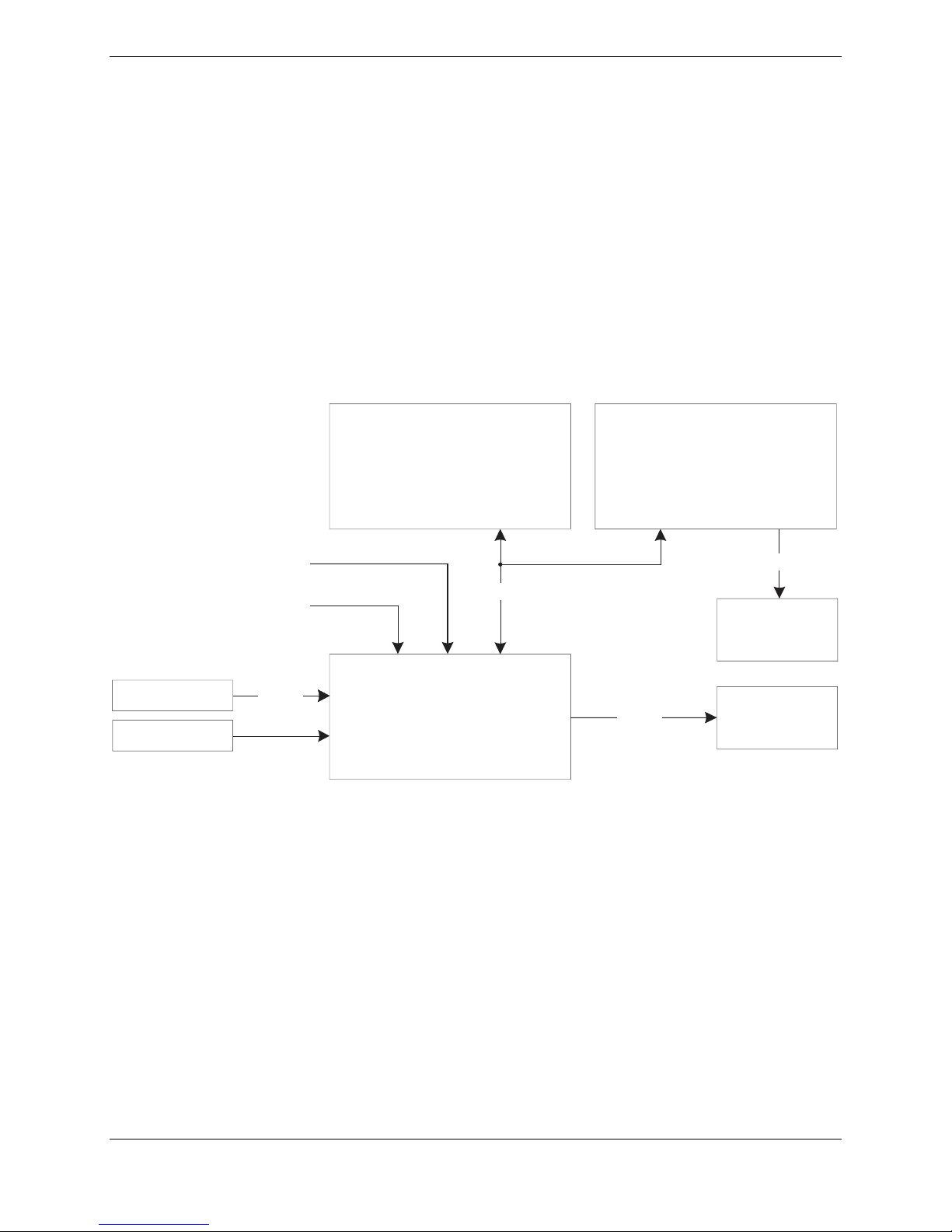
Figure 1-1 illustrates the communication paths that are in place in a typical G300 installation.
OPTIONAL
GDU 370
(PFD )
G
DU 375
(MFD)
GMU 44
GTP 59
Static
Pitot
RS-485
CAN
GSU 73
Figure 1-1. G300 Interconnect Summary
RS-232
RS-232
SL
(not included in
the G300 system)
40
GTX 327
(not included in
the G300 system)
Page 1-2 G300 Installation Manual –Installation Overview
Revision A 190-00921-01

1.4 General G300 LRU Specifications
1.4.1 Garmin LRU Part Numbers
Table 1-1. G300 LRU Part Numbers
LRU
Assembly Part
Number
Unit Only Part
Number
GDU 370 011-01747-10 010-00667-10
GDU 375 011-01747-30 010-00667-30
GMU 44 011-00870-00 010-00296-00
GSU 73 011-01817-00 010-00691-00
1.4.2 Power Specifications
All LRUs are capable of operating at either 14 or 28 VDC. See the individual LRU specific
Environmental Forms (Table 1-4) for details on surge ratings and minimum/maximum operating voltages.
See Table 1-2 for current draw specifications.
Table 1-2. G300 LRU Power Requirements
LRU Supply Voltage Current Draw
GDU 37X 9-29 Vdc
GMU 44 12Vdc (from GSU 73) Inc. in GSU Current Draw
GSU 73 9-29 Vdc
1.07 Amp @ 14Vdc
0.54 Amp @ 28Vdc
1.75 Amp @ 14Vdc (Max)
0.80 Amp @ 28Vdc (Max)
1.4.3 Physical Specifications
All width, height, and depth measurements are taken with unit rack (if applicable) and connectors.
Table 1-3. G300 LRU Physical Specifications
Depth
(GMU 44
LRU Width Height
Diameter,
Unit Weight
including
flange*)
GDU 370
GDU 375
GMU 44
GSU 73
6.04 inches
(153.4 mm)
6.04 inches
(153.4 mm)
N/A
5.50 inches
(139.8 mm)
7.83 inches
(198.8 mm)
7.83 inches
(198.8 mm)
2.10 inches
(5.33 cm)
3.96 inches
(100.6 mm)
3.41 inches
(86.7 mm)
3.41 inches
(86.7 mm)
*3.35 inches
(85.1 mm)
7.33 inches
(186.2 mm)
1.6 lbs
(0.713 kg)
1.7 lbs
(0.753 kg)
0.35 lbs.
(0.16 kg)
3.1 lbs
(1.41 kg)
Unit Weight
w/Nutplate
& Connector
Weight
1.8 lbs
(0.803 kg)
1.9 lbs
(0.843 kg)
0.50 lbs.
(0.23 kg)
3.5 lbs
(1.59 kg)
G300 Installation Manual – Installation Overview Page 1-3
190-00921-01 Revision A

1.4.4 Environmental Specifications
Refer to the applicable environmental form (Table 1-4) for a complete list of environmental
characteristics.
Table 1-4. G300 LRU Environmental Forms
Document Garmin Part Number
GMU 44 Environmental Qualification Form 005-00164-31
GTP 59 Environmental Qualification Form 005-00191-97
1.4.5 Cooling Requirements
• No cooling air is required for the GDU 37X
• No cooling air is required for the GMU 44
• No cooling air is required for the GSU 73, however the GSU 73 should be mounted in a location
that provides adequate airflow to comply with the maximum outer case temperature listed in
Section 4.
NOTE
Avoid installing the G300 LRUs near heat sources. If this is not
possible, ensure that additional cooling is provided. Allow adequate
space for installation of cables and connectors. The installer will supply
and fabricate all of the cables. All wiring should be in accordance with
FAA AC 43.13-1B and AC 43.13-2A.
1.5 Mounting
Refer to Section 2 through Section 6 for specific mounting instructions for each component of the G300,
and to Appendix A for Outline & Installation Drawings.
It may be necessary to mount the GSU 73 and/or the GMU44 remotely due to spacing/accessibility
concerns, or due to weight/balance requirements.
Page 1-4 G300 Installation Manual –Installation Overview
Revision A 190-00921-01

1.6 Wiring/Cabling Considerations
Use MIL-W-22759/16 (or other approved wire) AWG #24 or larger wire for all connections unless
otherwise specified. The standard pin contacts supplied in the connector kit are compatible with up to
AWG #22 wire. In cases where some installations have more than one LRU sharing a common circuit
breaker, sizing and wire gauge is based on aircraft circuit breaker layout, length of wiring, current draw
on units, and internal unit protection characteristics. Do not attempt to combine more than one unit on the
same circuit breaker unless it is specified on aircraft manufacturer approved drawings.
Ensure that routing of the wiring does not come in contact with sources of heat, RF or EMI interference.
Check that there is ample space for the cabling and mating connectors. Avoid sharp bends in cabling and
routing near aircraft control cables.
RG400 or RG142 coaxial cable with 50 Ω nominal impedance and meeting applicable aviation
regulations should be used for the installation.
Check that there is ample space for the cabling and mating connectors. Avoid sharp bends in cabling and
routing near aircraft control cables. Cabling for the G300 should not be routed near components or
cabling which are sources of electrical noise. Route the GPS antenna cable as far as possible away from
all COM transceivers and antenna cables.
1.6.1 Wiring Harness Installation
Allow adequate space for installation of cables and connectors. The installer shall supply and fabricate all
of the cables. Electrical connections are made through D subminiature connectors for the GDU 37X and
GSU 73 units, and through a round 9-pin connector for the GMU 44. Appendix A defines the electrical
characteristics of all input and output signals. Required connectors and associated hardware are supplied
with the connector kit.
CAUTION
Check wiring connections for errors before connecting any wiring
harnesses. Incorrect wiring could cause internal component damage.
G300 Installation Manual – Installation Overview Page 1-5
190-00921-01 Revision A
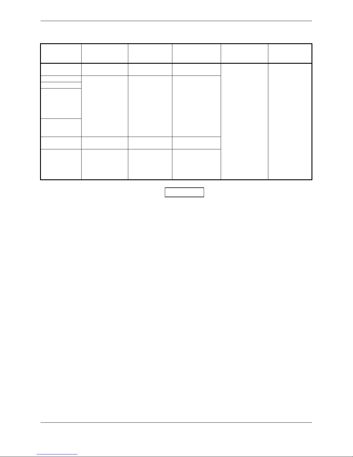
Table 1-5. Pin Contact and Crimp Tools Part Numbers
LRU Contact Type
GDU 37X
GSU 73
GTP 59
011-00979-20
(Config
module
w/EEPROM
kit)
011-00981-00
(thermocouple
kit)
GMU 44
011-00979-22
(Config
module
w/Sockets &
Jackscrew kit)
Socket, Mil
Crimp, Size 20
Pin, Mil Crimp,
Size 22D
Socket, Mil
Crimp, Size 20
Socket, Mil
Crimp, Size 20,
26-30 AWG
1. Insertion/Extraction tools from ITT Cannon are all plastic; others are plastic with metal tip.
2. Non-Garmin part numbers shown are not maintained by Garmin and consequently are subject
to change without notice.
Garmin
Contact Part
Number
336-00094-00
336-00021-00
336-00022-00
336-00022-01
Recommended
Positioner
M22520/2-08,
Daniels K13-1
Positronic P/N
9502-4,
ITT P/N
M22520/2-09,
Daniels P/N K42
M22520/2-08,
Daniels K13-1
Positronic P/N
9502-5
NOTES
Recommended
Insertion/
Extraction Tool
M81969/1-04
for size 22D
pins and
M81969/1-02
for size 20 pins
Recommended
Hand Crimping
Tool
M22520/2-01
1.6.2 Cable Location Considerations
Use cable meeting the applicable aviation regulation for the interconnect wiring. Any cable meeting
specifications is acceptable for the installation. When routing cables, observe the following precautions:
• All cable routing should be kept as short and as direct as possible.
• Avoid sharp bends.
• Avoid routing cables near power sources (e.g., 400 Hz generators, trim motors, etc.) or near
power for fluorescent lighting.
• Analog Input wires routed too close to spark plugs, plug wires, or magnetos may result in erratic
readings.
Page 1-6 G300 Installation Manual –Installation Overview
Revision A 190-00921-01
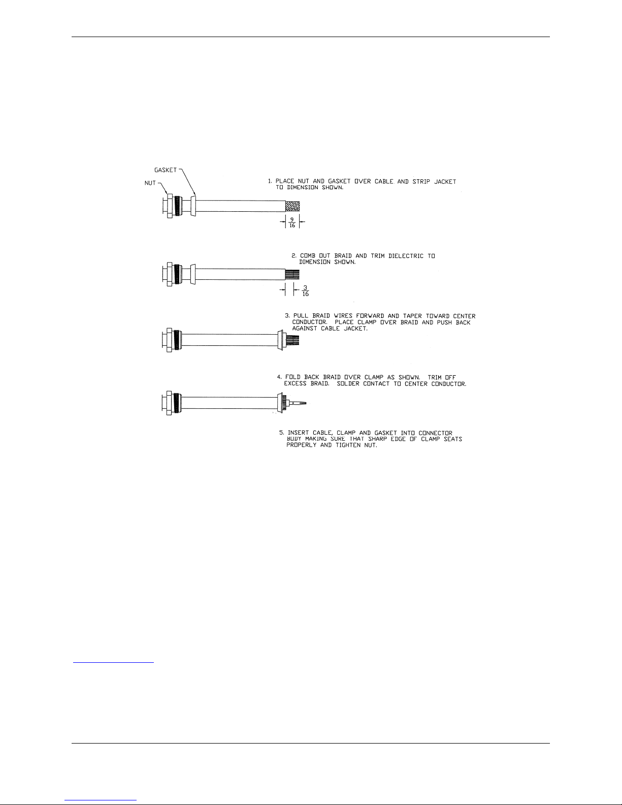
1.6.3 Cable Installation
1. Route the coaxial cable to the unit location. Secure the cable in accordance with good aviation
practice.
2. Trim the coaxial cable to the desired length and install the BNC connector (330-00087-00) per
the cabling instructions on Figure 1-2. If the connector is provided by the installer, follow the
connector manufacturer’s instructions for cable preparation.
Figure 1-2. Coaxial Cable Installation
3. Contacts for the 50, 62, and 78 pin connectors must be crimped onto the individual wires of
the aircraft wiring harness. Table 1-5 list contact part numbers (for reference) and
recommended crimp tools.
1.6.4 Backshell Assemblies
Connector kits include backshell assemblies. The backshell assembly houses the configuration module
and a thermocouple reference junction (if applicable). Garmin’s backshell connectors give the installer
the ability to quickly and easily terminate shield grounds at the backshell housing. The instructions
needed to install the Jackscrew Backshell (190-00313-11), Configuration Module (190-00313-10), and
Thermocouple (190-00313-01) can be downloaded from the Dealer portion of the Garmin website
www.garmin.com
.
G300 Installation Manual – Installation Overview Page 1-7
190-00921-01 Revision A

1.7 Antenna Considerations
1.7.1 GPS Antenna Location
Refer to Section 6 for GPS antenna location considerations.
1.7.2 Electrical Bonding
No special precautions need to be taken to provide a bonding path between the GPS antenna and the
aircraft structure.
1.7.3 VHF COM/GPS Interference
On some installation VHF COM transceivers, Emergency Locator Transmitter (ELT) antennas, and
Direction Finder (DF) receiver antennas can re-radiate through the GPS antenna. The GDU 37X does not
interfere with its own GPS receiver. However, placement of the GPS antenna relative to a COM
transceiver and COM antenna, ELT antenna, and DF receiver antenna is critical.
Use the following guidelines, in addition to others in this document, when locating the GDU 37X and its
antennas.
• GPS Antenna—Locate as far as possible from all COM antennas and all COM transceivers,
ELT antennas, and DF antennas. The GPS antenna is less susceptible to harmonic interference
if a 1.57542 GHz notch filter is installed on the COM transceiver antenna output.
• Locate the GDU 37X as far as possible from all COM antennas.
If a COM antenna is found to be the problem, a 1.57542 GHz notch filter (Garmin P/N 330-00067-00)
may be installed in the VHF COM coax, as close to the COM as possible.
If a COM is found to be radiating, the following can be done:
1. Replace or clean the VHF COM rack connector to ensure good coax ground.
2. Place grounding straps between the GDU 37X unit, VHF COM and a good ground.
3. Shield the VHF COM wiring harness.
Page 1-8 G300 Installation Manual –Installation Overview
Revision A 190-00921-01

2 GDU 37X
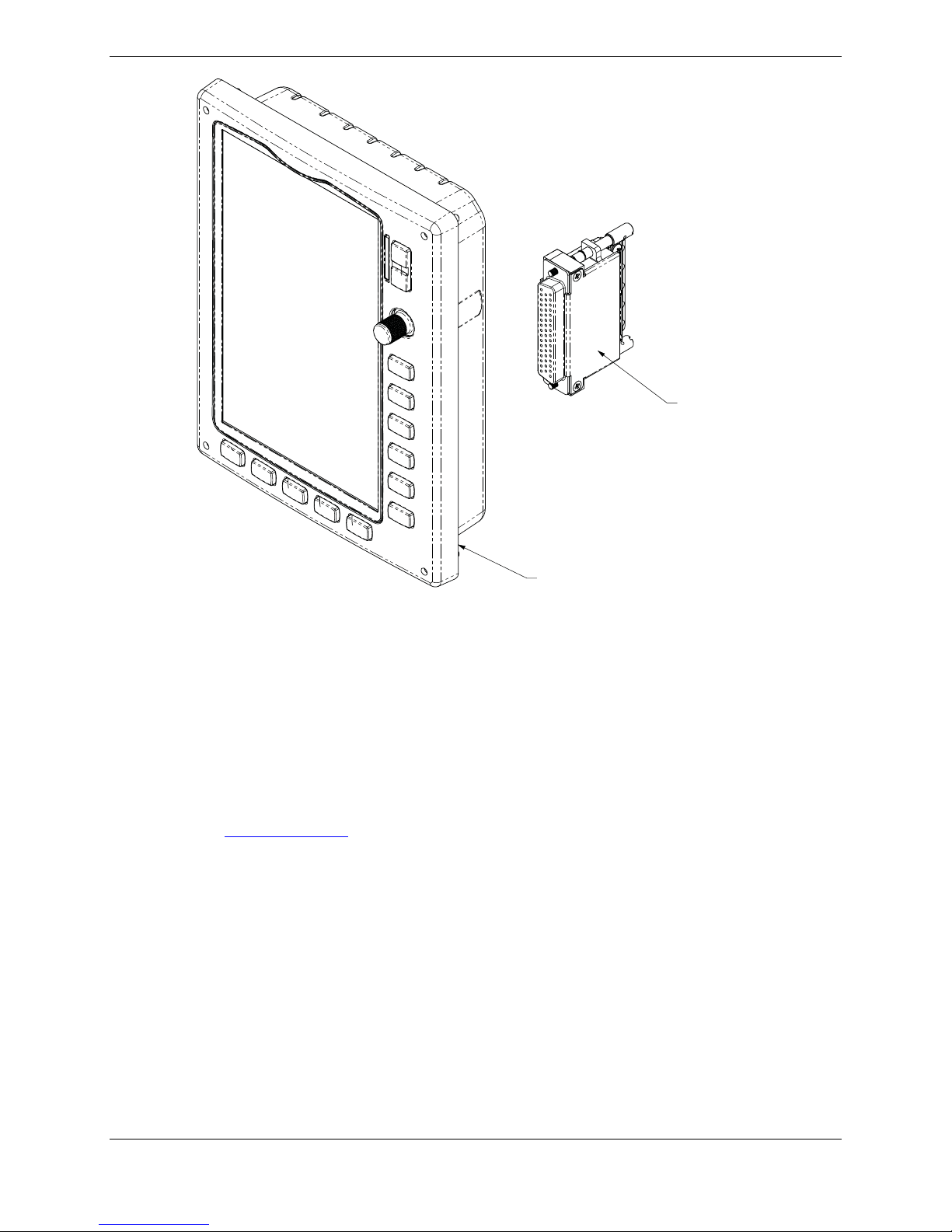
Figure 2-1. GDU 37X
2.1 Equipment Description
The GDU 37X provides a central display and user interface for the G300 Integrated Flightdeck System.
The display is mounted flush to the aircraft instrument panel using four #6 screws. A GDU 37X is
available in two models, GDU 370 and GDU 375. The GDU 370 is a Garmin Display Unit with a VFR
WAAS-GPS receiver. The GDU 375 provides these same features plus an XM receiver.
2.1.1 Flight Instrument Functions
• Display of attitude (pitch and roll), rate of turn, slip/skid, heading, airspeed, altitude, and vertical
speed information (single display installation, or on an MFD in reversionary mode)
• Display of engine and airframe instrumentation (single display installation, on a PFD in
reversionary mode, or on an MFD)
2.1.2 Navigation Functions
• Display of position and ground speed
• Display of stored navigation and map databases
• Control and display of the HSI, Selected Heading, and Selected Course (PFD or reversionary
modes only)
• Area navigation functions using the determined position/velocity and stored navigation data
• Advisory approach navigation functions and associated databases
G300 Installation Manual – GDU 37X Page 2-1
190-00921-01 Revision A

2.1.3 Interface Summary
The GDU 37X uses CAN and RS-232 communications interfaces. The GDU 37X communicates with the
following Garmin LRUs:
• Other GDU 37X
• GSU 73 ADAHRS/Engine LRU
• SL40 Comm Transceiver
2.2 Electrical Specifications
2.2.1 Electrical Characteristics
Table 2-1. GDU 37X Supply Voltages
Characteristics Specifications
Power Requirements 14/28 VDC
2.2.2 Power Consumption
Table 2-2. GDU 37X Power Requirements
LRU 14V (Maximum) 14V (Typical) 28V (Maximum) 28V (Typical)
GDU 370
GDU 375
15W, 1.10 Amp 8.5W, .600 Amp 15W, 0.540 Amp 8.5W, .300 Amp
15W, 1.10 Amp 9.5W, .675 Amp 15W, 0.540 Amp 9.25W, .330 Amp
2.2.3 GPS Specifications
The GDU 37X uses a WAAS enabled, high-sensitivity GPS receiver that continuously tracks and uses up
to 12 satellites to compute and update it’s position.
Table 2-3. GDU 37X GPS Specifications
Characteristics Specifications
Acquisition Time a) Warm Start (position known to 10 nm, time known to 10
minutes, with valid almanac and ephemeris): Less than 5
seconds
b) Cold Start (position known to 300 nm, time known to 10
minutes, with valid almanac): Less than 45 seconds
c) AutoLocate™ (with almanac, without initial position or
time): Less than 60 seconds
Update Rate 5/second, continuous
Positional Accuracy <10 meters
Velocity Accuracy 0.05 meter/sec steady state
Antenna power supply Voltage (4.5 to 5.0), current (50 mA max)
Max Input Signal 40dB
Page 2-2 G300 Installation Manual – GDU 37X
Revision A 190-00921-01

2.2.4 Antennas
The following is a list of antennas currently supported by the GDU 37X:
Table 2-4. GDU 37X Recommended Antennas
Model
Mount
Style
Conn
Type
SATCOM
Compatible Mfr
Antenna
Part
Number
Garmin
Order
Number
Comant 2480201
VHF/GPS
[1]
Comant 420-10
XM only
Antenna
Screw
Mount,
Teardrop
Footprint
Screw
Mount,
ARINC 743
Footprint
BNC
TNC
TNC NA Comant CI 420-10 N/A
Yes Comant CI 2480-201 N/A
[1] The GPS antenna connec tor is TNC type. The VHF COM antenna connector is BNC type.
2.3 Environmental Specifications
The GDU 37X has an Operating Temperature Range of -20°C to +60°C.
2.4 Installation Requirements
2.4.1 Required Accessories
Each of the following accessories is provided separately from the GDU 37X unit and is required to install
the unit (Figure 2-2).
Table 2-5. GDU 37X Required Accessories
Item Garmin P/N Quantity
GDU 37X Connector Kit 011-01921-00 1
Configuration Module w/Sockets, Jackscrew
(required for PFD only)
011-00979-22 1
Table 2-6. Contents of GDU 37X Connector Kit (011-01921-00)
Item Garmin P/N Quantity
Sub-Assy,bkshl w/Hdw,Jackscrew 011-01855-04 1
Conn, Rcpt,D-Sub, Crimp Socket, C 330-00625-50 1
Contact, Sckt, D-Sub, Crimp, Size 20 336-00094-00 20
2.4.2 Additional Equipment Required
A 3/32” hex drive tool is required to secure the GDU 37X to the panel as described in Section 2.7 Unit
Installation.
G300 Installation Manual – GDU 37X Page 2-3
190-00921-01 Revision A
CONNECTOR KIT
011-01921-00
GDU 37x UNIT
011-01747-( )
Figure 2-2. GDU 37X Mounting Accessories
2.5 Installation Considerations
Fabrication of a wiring harness is required. Sound mechanical and electrical methods and practices are
required for installation of the GDU 37X. Refer to Section 1.6 for wiring considerations, Appendix A.1
for pinouts.
Connector kits include backshell assemblies. The backshell assembly houses the configuration module (if
applicable). Garmin’s backshell connectors give the installer the ability to quickly and easily terminate
shield grounds at the backshell housing. The instructions needed to install the Jackscrew Backshell (19000313-11), and Configuration Module (190-00313-10) can be downloaded from the Dealer portion of the
Garmin website www.garmin.com
.
2.6 Mounting Requirements
Refer to Appendix B.1 for outline and installation drawings.
2.7 Unit Installation
The GDU 37X is installed by holding the unit flush with the instrument panel and fastening the four
captured 3/32” hex socket head screws to the panel as shown in Figure B-1.2.
2.8 Continued Airworthiness
Maintenance of the GDU 37X is “on condition” only. Periodic maintenance of the GDU 37X is not
required. Instructions for Continued Airworthiness (ICA) are not required for this product under 14 CFR
Part 21 since the GDU 37X has received no FAA approval or endorsement.
Page 2-4 G300 Installation Manual – GDU 37X
Revision A 190-00921-01

3. GMU 44
Figure 3-1. GMU 44 Unit View
3.1 Equipment Description
The Garmin GMU 44 Magnetometer is a remote mounted device that interfaces with a Garmin GSU 73 to
provide flight attitude and heading data for flight instrumentation.
An Attitude and Heading Reference System combines the functions of a Vertical Gyro and a Directional
Gyro to provide measurement of Roll, Pitch and Heading angles. The Garmin ADAHRS and
magnetometer replace traditional rotating mass instruments.
Using long-life solid-state sensing technology, the GMU 44 Magnetometer uses magnetic field
measurements to create an electronically stabilized AHRS.
The GMU 44 magnetometer provides magnetic information to support the function of the GSU 73. The
GSU 73 provides operating voltage to the GMU 44 Magnetometer.
3.1.1 Interface Summary
The following is an interface summary for the GMU 44.
• GMU 44 to GSU 73 Interface: Power, RS-232, RS-485 (19,200 baud)
3.2 Electrical Specifications
Table 3-1. GMU 44 Electrical Specifications
Specification Characteristic
Power Requirements
Including GMU 44
G300 Installation Manual – GMU 44 Page 3-1
190-00921-01 Revision A
Supply Voltage: 14/28 VDC. See the Environmental
Qualification Form for details on surge ratings and
minimum/maximum operating voltages. See Table 1-2 for
current specifications.

3.3 Environmental Specifications
Table 3-2 lists general environmental specifications. For detailed specifications, see the Environmental
Qualification Form (Garmin part number 005-00164-31) for the GMU 44.
Table 3-2. GMU 44 Environmental Specifications
Specification Characteristic
Regulatory Compliance RTCA/DO-160D Environmental Conditions and
EUROCAE/ED-14D
Unit Software RTCA/DO-178B Level B
Operating Temperature
Range
Altitude 55,000 Feet
-55° C to +70° C
3.4 Installation Requirements
3.4.1 Equipment Available
Table 3-3. GMU 44 Part Numbers
Model
GMU 44 010-00296-00 011-00870-00 No
Catalog Part
Number
Table 3-4. GMU 44 Accessories
Unit Part Number Installation Rack
Item Garmin P/N Quantity
Sub Assy, Connector Kit, GMU 44 011-00871-00 1
Installation Rack, GMU 44 115-00481-00 1
3.5 Installation Considerations
The following guidelines describe proper mechanical installation of the Garmin GMU 44 Magnetometer.
The guidelines include requirements for proper location selection in the aircraft, requirements for
supporting structure and mechanical alignment and restriction on nearby equipment.
Fabrication of a wiring harness is required. Sound mechanical and electrical methods and practices are
required for installation of the GMU 44. Refer to Section 1.6 for wiring considerations and to Appendix
A.2 for pinouts.
The instructions needed to assemble the circular connector (190-00313-12) can be downloaded from the
Dealer portion of the Garmin website www.garmin.com
The GMU 44 is an extremely sensitive three-axis magnetic sensor. It is more sensitive to nearby
magnetic disturbances than a flux gate magnetometer. For this reason, when choosing a mounting
location for the GMU 44, observe the following distances from objects or devices that can disturb the
magnetic field. Table 3-5 specifies required distances from magnetic disturbances for GMU 44 location.
Page 3-2 G300 Installation Manual – GMU 44
Revision A 190-00921-01
.

Table 3-5. Required Distance from Magnetic Disturbances
Disturbance Source Minimum Distance from GMU 44
Electric motors and relays, including servo motors 10 feet (3.0 meters)
Ferromagnetic structure greater than 1 kg total
8.2 feet (2.5 meters)
(iron, steel, or cobalt materials, especially landing
gear structure)
Ferromagnetic materials less than 1 kg total, such
3 feet (1.0 meter)
as control cables
Any electrical device drawing more than 100 mA
3 feet (1.0 meter)
current
Electrical conductors passing more than 100 mA
3 feet (1.0 meter)
current [(must be twisted shielded pair if within 10
feet (3.0 meters)]
Electrical devices drawing less than 100 mA current 2 feet (0.6 meter)
Magnetic measuring device (e.g. installed flux
2 feet (0.6 meter)
gates, even if unpowered)
Electrical conductors passing less than 100 mA
1.3 feet (0.4 meter)
current [(must be twisted shielded pair if within 10
feet (3.0 meters)]
Ensure that any electrical conductor that comes within 10 feet (3.0 meters) of the GMU 44 is installed as a
twisted shielded pair, not a single-wire conductor. (If possible, the shield should be grounded at both
ends.)
Use nonmagnetic materials to mount the GMU 44, and replace any magnetic fasteners within 0.5 meter
with nonmagnetic equivalents (e.g. replace zinc-plated steel screws used to mount wing covers or
wingtips with nonmagnetic stainless steel screws.)
In general, wing mounting of the GMU 44 magnetometer is strongly preferred. Fuselage mounting is
strongly discouraged because of numerous potential disturbances that interfere with accurate operation.
Mechanical mounting fixtures for the GMU 44 must be rigidly connected to the aircraft structure. Use of
typical aircraft-grade materials and methods for rigid mounting of components is acceptable, so long as
adequate measures are taken to ensure a stiffened mounting structure.
Align the GMU 44 mounting rack to within 3.0° of the aircraft level reference in pitch and roll.
Align the GMU 44 mounting rack’s forward direction to within 0.5° in heading of the aircraft forward
direction (longitudinal axis). If it is not possible to guarantee this accuracy, installation alignment to
within 2.5° in heading is acceptable in combination with a post-installation heading alignment of the
aircraft to a precise heading to determine and set a heading offset. The heading offset procedure is
described in Section 9.3.4.
It is strongly preferred that the GMU 44 alignment is within 0.5° of the aircraft longitudinal axis, rather
than using the heading offset procedure.
G300 Installation Manual – GMU 44 Page 3-3
190-00921-01 Revision A

3.5.1 Consideration for Wing Grounded Lighting Fixtures
The following installation practices are recommended if the required GMU 44 mounting bracket is
located in the wing.
1. The wing tip lights should not have a power ground referenced to the chassis of the light
assembly that would then be referenced back to the airframe ground via the light assembly
mounting.
2. A dedicated power ground should be used and returned as a twisted pair with the power source
back into the fuselage for a wing mounted GMU 44.
These installation practices will prevent magnetically interfering currents from flowing in the wing skin
that encloses the GMU 44. Electrically isolating the light assembly should not be used as an alternative to
item 1 above, unless the isolated light assembly has been analyzed for adequate protection against direct
attachment of lighting.
Refer to Appendix B.2 for outline and installation drawings.
Page 3-4 G300 Installation Manual – GMU 44
Revision A 190-00921-01

3.6 GSU 73/GMU 44 Interconnect Harness Fabrication Instructions
Table 3-6 lists parts needed for the GMU 44 interconnect harness. Some of the parts for installation are
included in the GMU 44 Connector Installation Kit. Other parts are provided by the installer. Reference
numbers refer to item bubble numbers shown in Figure B-2.4.
Table 3-6. Parts Needed for GMU 44 Installation
Figure B-2.4 Ref Description
1
Shield Termination
(method optional)
Qty.
Included
0
GPN or MIL Spec
Parts used depend on method
chosen
2 Shield Extension Wire 0 M22759/16-22
3, 4, 9 GMU 44 Connector Kit 1 011-00871-00
5 3-Conductor Cable 0 M27500-22TE3T14
6 2-Conductor Cable 0 M27500-22TE2T14
Table 3-7 lists material in the GMU 44 connector kit and the associated reference number, as shown in
Figure B-2.4. The GMU 44 magnetometer has an attached pigtail with male polarity. The harness
connector for the GMU 44 has female polarity.
Table 3-7. GMU 44 Connector Kit (011-00871-00) Contents, Reference Figure B-2.4
Item Garmin P/N Quantity Figure B-2.4 Ref
Screw,6-32x.250,PHP,BR,w/Nyl 211-60037-08 3 9
Conn,Circular,Female,9 Ckt 330-00360-00 1 4
Backshell,Circular,Kit,SS 330-90005-01 1 4
Cont,Sckt,Mil Crp,Size 20 336-00022-00 10 3
G300 Installation Manual – GMU 44 Page 3-5
190-00921-01 Revision A

3.7 Mounting Instructions
After ensuring that requirements are met, assemble the GMU 44 mounting plate kits according to the
dimensions given in Appendix B.2. Install the unit assemblies.
Mount the GMU 44 to its mounting plate, taking care to tighten the mounting screws firmly. Use of nonmagnetic tools (e.g. beryllium copper or titanium) is recommended when installing or servicing the
GMU 44. Do not
The metal components in the GMU 44's connector may slightly affect the magnetic field sensed by the
GMU 44. Place the connector at least 2 inches from the body of the GMU 44 to minimize this effect.
After attaching the GMU 44's connector to its mate in the aircraft wiring, secure the connector in place
using good installation practices. This will ensure that any remaining magnetic effect can be
compensated for using Calibration Procedure C: Magnetometer Calibration.
use a screwdriver that contains a magnet when installing or servicing the GMU 44.
NOTE
If the GMU 44 is ever removed, the anti-rotation properties of the
mounting screws must be restored. This may be done by replacing the
screws with new Garmin PN 211-60037-08. If original screws must be
re-used, coat screw threads with Loctite 242 (blue) thread-locking
compound, Garmin PN 291-00023-02, or equivalent. Important:
Mounting screws must be brass.
3.8 Continued Airworthiness
Maintenance of the GMU 44 is ‘on condition’ only. Periodic maintenance of the GMU 44 is not required.
Page 3-6 G300 Installation Manual – GMU 44
Revision A 190-00921-01
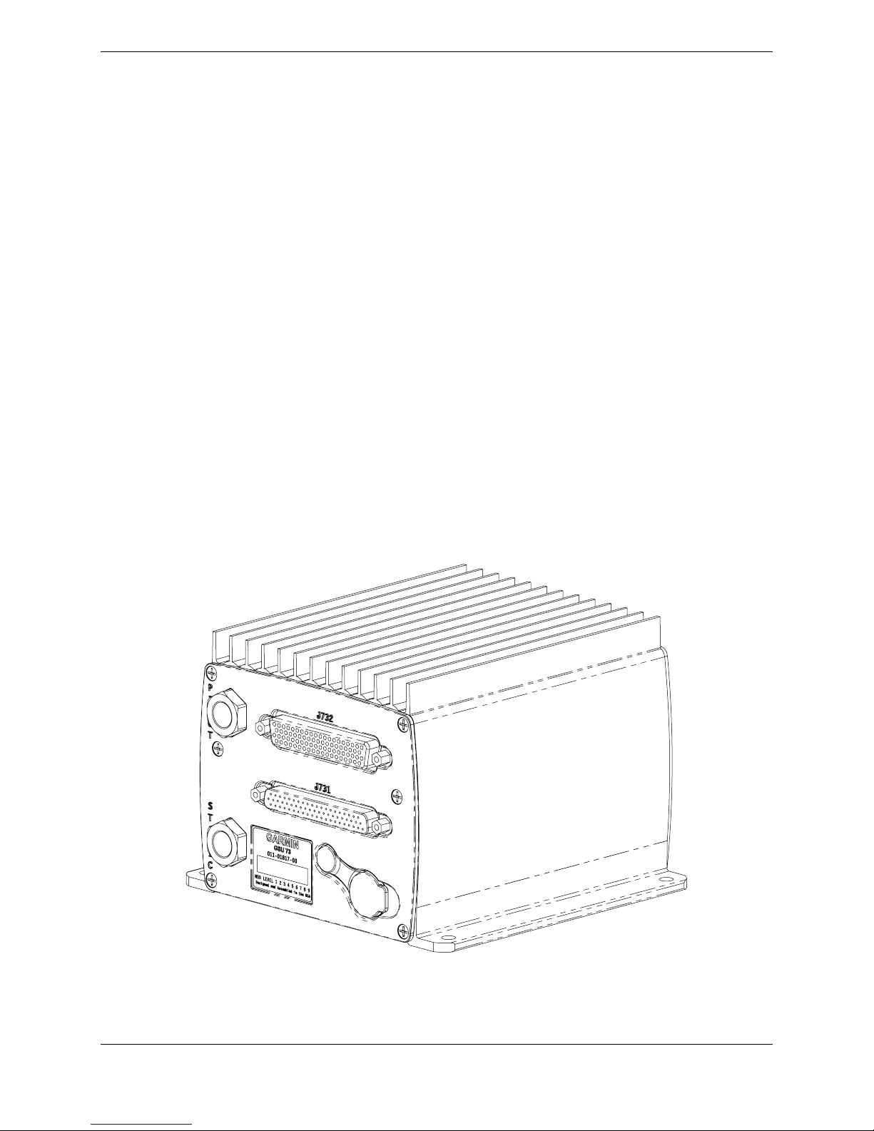
4 GSU 73
4.1 Equipment Description
The GSU 73 is intended for the OEM LSA (light sport aircraft) and experimental aircraft markets. The
Garmin GSU 73 Sensor Unit is not a TSO-certified product and has received no FAA approval or
endorsement. The GSU 73 is intended to be used as a part of the G300, and it is not suitable for certified
configurations.
The GSU 73 is an LRU that provides AHRS and Air Data information as well as an interface to
Engine/Airframe sensors in a single mechanical package. The GSU 73 interfaces to a remote mounted
GMU 44 for heading information and also computes OAT and TAS from inputs provided by the GTP 59.
The GSU 73 is capable of maneuvers through a range of 360° in bank and pitch. The rotation rate
capability is ±200° per second.
Bank error and pitch error are within ±1.25° over the range of 30° bank, left and right, and 15° pitch nose
up and nose down. Heading is accurate to within 2° in straight and level flight.
Operation is not authorized north of 70° North latitude nor south of 70° South latitude due to unsuitability
of the magnetic fields near the Earth’s poles. In addition, operation is not authorized in the following two
regions:
1) North of 65° North latitude between longitude 75° W and 120° W. (Northern Canada)
2) South of 55° South latitude between longitude 120° E and 165° E. (Region south of Australia and
New Zealand)
G300 Installation Manual – GSU 73 Page 4-1
190-00921-01 Revision A
Figure 4-1. GSU 73 Unit View

4.1.1 Features Summary
Air Data Interfaces
Pressure Altitude CAN (1)
Density Altitude RS-232 (2 TX/2 RX)
Vertical Speed ARINC 429 (4 RX/2 TX)
Mach Number OAT Probe (GTP 59)
Indicated Airspeed Magnetometer (GMU 44) (1 RS-232 TX/ 1 RS-485 RX)
True Airspeed
AHRS
Engine/Airframe
Magnetic Heading 28 Analog inputs, including those allocated as per below:
Pitch Angle Dedicated Ammeters (2)
Roll Angle Constant Current Source Capability (6)
Linear Accelerations Divider Circuits to handle large input voltages (12)
Pitch, Roll, Yaw Rotation Rates Frequency Counter Inputs (4)
Discrete I/O (4 In/2 Out)
4.2 Electrical Specifications
Table 4-1. GSU 73 Supply Specifications
Characteristic Specification
Input Voltage Range 9-29 Vdc
Power Input 1.75 Amp @ 14 Vdc (Max)
0.80 Amp @ 28 Vdc (Max)
Page 4-2 G300 Installation Manual – GSU 73
Revision A 190-00921-01
 Loading...