

Garmin GMA 340, GMA 340H, GMA 340 DUAL ADF Installation Manual

GMA 340 AUDIO PANEL
INSTALLATION MANUAL
(GMA 340, GMA 340H,
GMA 340 DUAL ADF)
(GMA 340 and GMA 340 Dual ADF Shown)
Garmin International, Inc.
1200 E. 151st Street
Olathe, KS 66062 USA
190-00149-01 Revision L
June 2003
£

© Copyright 2003
Garmin Ltd. or its subsidiaries
All Rights Reserved
Except as expressly provided herein, no part of this manual may be reproduced, copied, transmitted,
disseminated, downloaded or stored in any storage medium, for any purpose without the express prior
written consent of Garmin. Garmin hereby grants permission to download a single copy of this manual and
of any revision to this manual onto a hard drive or other electronic storage medium to be viewed and to
print one copy of this manual or of any revision hereto, provided that such electronic or printed copy of
this manual or revision must contain the complete text of this copyright notice and provided further that
any unauthorized commercial distribution of this manual or any revision hereto is strictly prohibited.
Information in this document is subject to change without notice. Visit the Garmin web site
(www.garmin.com) for current updates and supplemental information concerning the operation of this and
other Garmin products.
Garmin International, Inc.
1200 E. 151
Olathe, KS 66062 USA
Telephone: 913-397-8200
Aviation Panel-Mount Technical Support Line (Toll Free) 1-888-606-5482
Dealer Line: 1-800-800-1420
Web Site Address: www.garmin.com
Garmin (Europe) Ltd.
Unit 5, Quadrangle, Abbey Park Industrial Estate
Romsey, SO51 9DL, U.K.
Telephone: 44/1794.519944
st
Street
INFORMATION SUBJECT TO EXPORT CONTROL LAWS
This document may contain information which is subject to the Export Administration Regulations
(“EAR”) issued by the United States Department of Commerce (15 CFR, Chapter VII, Subchapter C) and
which may not be exported, released, or disclosed to foreign nationals inside or outside of the United States
without first obtaining an export license. A violation of the EAR may be subject to a penalty of up to 10
years imprisonment and a fine of up to US$1,000,000 under Section 2410 of the Export Administration
Act of 1979. Include this notice with any reproduced portion of this document.
RECORD OF REVISIONS
Revision Revision
Date
A
B
C
D
E
F
G
01/27/98 Preliminary Release -
03/05/98 Add Music Trip Level Adjustment 8512
02/03/99 Add Marker Sens Adjustment and Crimp Tool P/N 10404
02/15/99 Add JTSO’s 10487
05/28/99 Updated Document 11122
05/26/00 Redraw 13446
04/27/01 Add 340H P/N, STC, Mod 1 Normal/Split Com
Description ECO #
15687
Mode Connections, Helicopter PTT Switch
H
J
K
L
Page A GMA 340 Installation Manual
Rev. L 190-00149-01
05/18/01 Added Dual ADF Version 15847
12/18/01 Add mono/stereo failsafe note 17123
06/24/02 Add 20 dB Music Volume Control and mod history 18443
06/30/03 Add SB0213 and SB0221 21559

TABLE OF CONTENTS
SECTION 1
GENERAL INFORMATION
PARAGRAPH PAGE
1.1 INTRODUCTION............................................................................................................................. 1-1
1.2 GENERAL DESCRIPTION ............................................................................................................. 1-1
1.3 SPECIFICATIONS ........................................................................................................................... 1-2
1.4 EQUIPMENT.................................................................................................................................... 1-3
1.5 INSTALLATION ACCESSORIES .................................................................................................. 1-3
1.6 ADDITIONAL EQUIPMENT REQUIRED..................................................................................... 1-4
1.7 LIMITED WARRANTY .................................................................................................................. 1-5
SECTION 2
INSTALLATION
2.1 INTRODUCTION............................................................................................................................. 2-1
2.2 UNPACKING AND INSPECTING EQUIPMENT.......................................................................... 2-1
2.3 ANTENNA INSTALLATION.......................................................................................................... 2-1
2.3.1 Location Considerations................................................................................................................. 2-1
2.3.2 Antenna Installation........................................................................................................................ 2-1
2.3.3 Antenna Cable Installation ............................................................................................................. 2-1
2.3.4 Installation Approval Considerations for Pressurized Aircraft ...................................................... 2-2
2.4 GMA 340 INSTALLATION............................................................................................................. 2-2
2.5 REAR CONNECTIONS ................................................................................................................... 2-3
2.5.1 Location.......................................................................................................................................... 2-3
2.5.2 Audio Shield Termination .............................................................................................................. 2-5
2.5.3 Noise............................................................................................................................................... 2-6
2.6 POST INSTALLATION CHECKOUT ............................................................................................ 2-6
2.6.1 Lamp Test....................................................................................................................................... 2-6
2.6.2 Failsafe Operation Check ............................................................................................................... 2-7
2.6.3 Transceiver Operational Check ...................................................................................................... 2-7
2.6.4 Intercom System (ICS) Check........................................................................................................ 2-7
2.6.5 Aircraft Receivers Check................................................................................................................ 2-8
2.6.6 Music System Check ...................................................................................................................... 2-8
2.7 ADJUSTMENTS ............................................................................................................................. 2-9
GMA 340 Installation Manual Page i
190-00149-01 Rev. L

SECTION 3
OPERATION
PARAGRAPH PAGE
3.1 OPERATION .................................................................................................................................... 3-1
3.1.1 Front Panel Controls....................................................................................................................... 3-1
3.1.2 On, Off, and Failsafe Operation ..................................................................................................... 3-2
3.1.3 Lighting .......................................................................................................................................... 3-2
3.1.4 Transceivers ................................................................................................................................... 3-2
3.1.5 Split Com........................................................................................................................................ 3-3
3.1.6 Com Swap Function ....................................................................................................................... 3-3
3.1.7 Aircraft Radios & Navigation ........................................................................................................ 3-3
3.1.8 Speaker Output ............................................................................................................................... 3-3
3.1.9 PA Function.................................................................................................................................... 3-4
3.1.10 Auxiliary Entertainment Inputs ...................................................................................................... 3-4
3.1.11 Intercom System (ICS) ................................................................................................................... 3-4
3.1.12 Mono/Stereo Headset ..................................................................................................................... 3-5
3.1.13 Marker Beacon Receiver ................................................................................................................ 3-6
APPENDIX A
CERTIFICATION DOCUMENTS
A.1 CONTINUED AIRWORTHINESS ................................................................................................. A-1
A.2 ENVIRONMENTAL QUALIFICATION FORM ........................................................................... A-4
APPENDIX B
INSTALLATION DRAWINGS
B.1 GENERAL ........................................................................................................................................B-1
APPENDIX C
STC PERMISSION
C.1 GENERAL ........................................................................................................................................C-1
Page ii GMA 340 Installation Manual
Rev. L 190-00149-01

LIST OF ILLUSTRATIONS
FIGURE PAGE
2-1 REAR CONNECTORS..................................................................................................................... 2-3
2-2 AUDIO SHIELD TERMINATION .................................................................................................. 2-5
2-3 ACCESS HOLE LOCATION........................................................................................................... 2-9
3-1 GMA 340 FRONT PANEL............................................................................................................... 3-1
B1 GMA 340 OUTLINE DRAWING ....................................................................................................B-3
B2 CONNECTOR/RACK KIT DRAWING ..........................................................................................B-5
B3 GMA 340 RECOMMENDED PANEL CUTOUT DIMENSIONS .................................................B-7
B4 J1 INTERCONNECT WIRING DIAGRAM ....................................................................................B-9
B5 J2 INTERCONNECT WIRING DIAGRAM ..................................................................................B-11
B6 J1 INTERCONNECT WIRING DIAGRAM ..................................................................................B-13
B7 J2 INTERCONNECT WIRING DIAGRAM ..................................................................................B-15
LIST OF TABLES
Table PAGE
2-1. J1 and J2 Pin Assignments ................................................................................................................ 2-4
2-2. Recommended Crimp tools............................................................................................................... 2-5
GMA 340 Installation Manual Page iii
190-00149-01 Rev. L
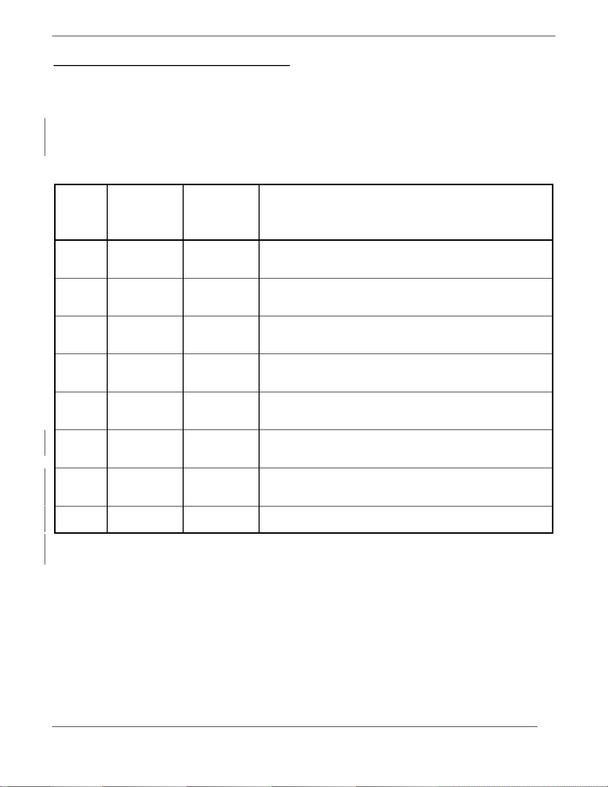
GMA 340 HARDWARE MOD LEVEL HISTORY
The following table identifies hardware modification (Mod) Levels for the GMA 340 audio panel. Mod
Levels are listed with the associated service bulletin number, service bulletin date, and the purpose of the
modification. The table is current at the time of publication of this manual (see date on front cover) and is subject
to change without notice. Authorized Garmin Sales and Service Centers are encouraged to access the most up-todate bulletin and advisory information on the Garmin Dealer Resource web site at www.garmin.com using their
Garmin-provided user name and password.
MOD
LEVEL
SERVICE
BULLETIN
SERVICE
BULLETIN
NUMBER
1 0103 2-2-01
2 0113 6-13-01
3 0208B 5-17-02
4 0209 5-2-02
5 0210 5-2-02
6 0212 7-16-02
7 0213 8-26-02
PURPOSE OF MODIFICATION
DATE
Configurable option to mute other com audios when
transmitting.
Provides times ten gain (20 dB) for entertainment music
system.
Provides correct marker beacon output loading for interface
with a Sandel SN3308 EHSI.
Provides failsafe operation when monophonic headsets are
used in a stereo installation.
Provides switchable On/OFF times ten gain (20 dB) for
entertainment music system.
Filter capacitors added to prevent power supply noise from
interfering with a GDL 49.
Prevents current limiting resistors from becoming shorted to
the chassis.
8 0221 *
* Not released at time of publication.
Page iv GMA 340 Installation Manual
Rev. L 190-00149-01
Adds a failsafe warning audio to the GMA 340.

SECTION 1
GENERAL INFORMATION
1.1 INTRODUCTION
This manual provides the installation and operating instructions for the Garmin GMA 340, GMA 340H and
GMA 340 Dual ADF Audio Panel. Reference to GMA 340 throughout this manual refers to all versions of the
unit. Information pertaining to the maintenance of the unit can be found in the GMA 340 Maintenance Manual,
P/N 190-00149-02. After installation of the GMA 340, FAA Form 337 must be completed by an appropriately
certificated agency to return the aircraft to service.
1.2 GENERAL DESCRIPTION
The Garmin GMA 340 Audio Panel meets the needs of aircraft owners and operators who require reliability and
versatility in the essential audio switching function. LED-illuminated push-button simplicity and intuitive panel
layout allow audio selection of both NAV and COM audio. Large, single-button activation of the COM
microphone and audio for up to three COM transceivers simplifies cockpit workload. Photocell dimming
circuitry automatically adjusts the brightness of the LEDs to a level appropriate for ambient cockpit light. A failsafe circuit connects the pilot’s headset and microphone directly to COM1 in the event that power is interrupted
or the unit is turned off. In the event of power loss a fail-safe warning audio will be heard.
Additionally, the GMA 340 includes a six-position intercom (ICS) with electronic cabin noise de-emphasis, two
stereo music inputs, and independent pilot, copilot, and passenger volume controls. To further simplify the
cockpit workload, the intercom provides three selectable modes of isolation. One hundred percent solid state
circuitry and extensive use of surface mount technology are employed. A pilot-selectable cabin speaker output
can be used to listen to the selected aircraft radios or to broadcast PA announcements. The PA function is pilot
selectable.
The GMA 340 is FAA TSO approved to C50c and C35d and JTSO approved to C50c and 2C35d. Also standard
is the marker beacon receiver with dual sensitivity and audio muting with automatic re-arming. 14V or 28V
operation, including the full rated range of headphone and speaker output power, is available without the
requirement for external voltage converters or dropping resistors. The GMA 340 is the standard version audio
panel as pictured on the cover of this manual. The GMA 340H is the helicopter version in which the pilot and copilot control knobs on the front panel are reversed. The GMA 340 Dual ADF version, also pictured on the cover,
accepts two ADF audio inputs.
Features Summary:
• User-friendly, intuitive front panel layout
• LEDs indicate selected function
• Six position intercom: pilot, copilot, four passengers
• Three stereo headset amplifiers: one for pilot, one for copilot, and one for the passengers
• Two stereo music source inputs (one in Dual ADF version)
• Three selectable intercom operational modes
• Selectable aural pushbutton annunciation (beep) for the crew.
GMA 340 Installation Manual Page 1-1
190-00149-01 Rev. L

• Independent pilot, copilot, and passenger volume controls
• Individual VOX circuits for each of six (6) mic inputs
• Automatic selection of radio audio source when corresponding mic is selected
• MASQ
TM
Processing
• Split COM transceiver function. Copilot may transmit and receive on COM2 while pilot
transmits and receives on COM1
• COM swap function
• TX indication
• SmartMute
TM
marker audio muting
• Speaker output for radios or PA function
• Power-off fail-safe to connect Pilot PTT, mic, and Headset to COM 1 if unit is turned off
• Power loss fail-safe warning audio
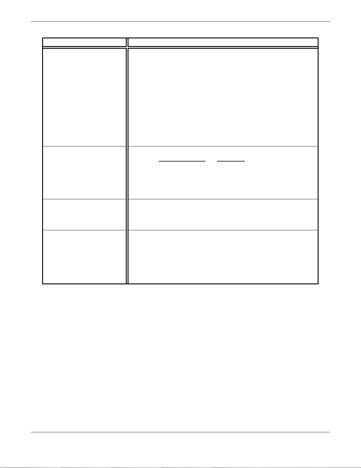
1.3 SPECIFICATIONS
SPECIFICATION CHARACTERISTIC
TSO Compliance TSO-C50c, C35d, JTSO-C50c, and JTSO-2C35d using DO-160C,
DO-170, and DO-143
Temperature Range
-20°C to +55°C
Weight (Unit Only) 1.2 lbs. (0.6 kg)
(Installed with rack and connectors) 1.7 lbs. (0.8 kg)
Physical Dimensions: Bezel Height: 1.30 inches (33 mm)
Bezel Width: 6.29 inches (160 mm)
Rack Height (Dimple to Dimple): 1.33 inches (34 mm)
Rack Width: 6.30 inches (160 mm)
Depth Behind Panel with
7.12 inches (181 mm)
Connectors (measured from
face of aircraft panel to rear
of connector backshells)
Power Requirements Supply Voltage: 11.0 to 33.0 VDC; Operating Current: 2.2 A (normal
operation, 13.8 V, speaker on)
Altitude 50,000 Feet
Audio Panel Transceiver inputs: 3
Receiver inputs: 5 (6 in Dual ADF version)
Unswitched inputs: 2
Input impedance: 500
ȍ (800ȍ DME input in Dual ADF)
Input isolation: 60 dB minimum
Special functions: Fail-safe operation
MASQ
TM
processing
Page 1-2 GMA 340 Installation Manual
Rev. L 190-00149-01
SPECIFICATION CHARACTERISTIC
Intercom Positions: 6 (pilot, copilot, 4 passengers)
Volume controls: 3 (pilot, copilot, passengers)
VOX level controls: 2 (pilot, copilot/passengers)
VOX circuits: 6 (one per mic input)
Music inputs (stereo): 2 (1 in Dual ADF version) (one input mutable)
Music input impedance: 460 ohms minimum
Music input level: Less than 500 mVac RMS for full output (typical).
1 Vac RMS MAX (3 Vac p-p)
Microphone signal processing: 9 pole characteristic and special cabin
noise band de-emphasis
Intercom isolation modes: 3
Special functions: Configurable aural push-button annunciation for
the crew
Headphone Outputs Output amplifiers: 3, stereo (pilot, copilot, passengers)
Fidelity: Power into 150ȍ Distortion
50 mW <0.5%
100 mW <5%
Frequency response: music; 100 Hz to 15 kHz nominal
Aircraft radio: 100 Hz to 6 kHz nominal
ICS mic: (Special cabin noise band de-emphasis)
Speaker Outputs Outputs selectable: 1, pilot selectable
Output power: 10 Watts into 4 or 8
ȍ, @ any normal supply voltage.
Frequency response: 350 Hz to 6 kHz nominal
Special functions: PA Mode, pilot selectable, including split operation
Marker Beacon Receiver Frequency: Crystal controlled at 75 MHz
Sensitivity: LO 1000 µV hard; HI 200 µV hard
Selectivity: 6 dB @ ±10 kHz min, 40 dB @ ±200 kHz max.
Input impedance: 50
ȍ
External lamp drive: 125 mA max each output
Other outputs: Middle MKR sense
Special functions: SmartMute
TM
marker audio muting
1.4 EQUIPMENT
GMA 340 Audio Panel, Ship Level Assembly, P/N 010-00152-( ) includes the following, depending on part
number:
• 011-00401-( ) GMA 340 Unit Assembly (011-00401-10 replaces 011-00401-00)
• 011-00652-00Connector Kit, GMA 340
• 011-00678-00Rack Backplate, GMA 340
• 115-00262-00SMP, Install Rack, GMA 340
(The installation kit is the same for the GMA 340, GMA 340H and GMA 340 Dual ADF)
1.5 INSTALLATION ACCESSORIES
• Marker beacon antenna kit (P/N 010-10175-00). [Note: A marker beacon antenna approved to
TSO C35( ) that has been installed to meet the requirements of this manual may be approved for
use with the GMA 340].
GMA 340 Installation Manual Page 1-3
190-00149-01 Rev. L

1.6 ADDITIONAL EQUIPMENT REQUIRED
• Antenna sealant (use manufacturer’s instructions, install according to FAA AC 43.13-2A).
• Cables: The installer will fabricate and supply all system cables. Interconnect wiring diagrams
are detailed in Appendix B.
• Hardware: #6-32 100
° flat head screw (6 ea.) and #6-32 self-locking nut (6 ea.). Hardware
required to mount the installation rack is not provided.
• Stereo headphone jacks (up to 6), microphone jacks (up to 6), 3.5mm stereo jacks (up to 2), and
insulating washers for all.
Page 1-4 GMA 340 Installation Manual
Rev. L 190-00149-01

1.7 LIMITED WARRANTY
This Garmin product is warranted to be free from defects in materials or workmanship for one year from
the date of purchase. Within this period, Garmin will at its sole option, repair or replace any
components that fail in normal use. Such repairs or replacement will be made at no charge to the
customer for parts or labor, provided that the customer shall be responsible for any transportation cost.
This warranty does not cover failures due to abuse, misuse, accident or unauthorized alteration or
repairs.
THE WARRANTIES AND REMEDIES CONTAINED HEREIN ARE EXCLUSIVE AND IN LIEU
OF ALL OTHER WARRANTIES EXPRESS OR IMPLIED OR STATUTORY, INCLUDING ANY
LIABILITY ARISING UNDER ANY WARRANTY OF MERCHANTABILITY OR FITNESS FOR A
PARTICULAR PURPOSE, STATUTORY OR OTHERWISE. THIS WARRANTY GIVES YOU
SPECIFIC LEGAL RIGHTS, WHICH MAY VARY FROM STATE TO STATE.
IN NO EVENT SHALL GARMIN BE LIABLE FOR ANY INCIDENTAL, SPECIAL, INDIRECT OR
CONSEQUENTIAL DAMAGES, WHETHER RESULTING FROM THE USE, MISUSE, OR
INABILITY TO USE THIS PRODUCT OR FROM DEFECTS IN THE PRODUCT. Some states do
not allow the exclusion of incidental or consequential damages, so the above limitations may not apply
to you.
Garmin retains the exclusive right to repair or replace the unit or software or offer a full refund of the
purchase price at its sole discretion. SUCH REMEDY SHALL BE YOUR SOLE AND EXCLUSIVE
REMEDY FOR ANY BREACH OF WARRANTY.
To obtain warranty service, contact your local Garmin Authorized Service Center. For assistance in
locating a Service Center near you, call Garmin Customer Service at one of the numbers shown below.
Products sold through online auctions are not eligible for rebates or other special offers from Garmin.
Online auction confirmations are not accepted for warranty verification. To obtain warranty service, an
original or copy of the sales receipt from the original retailer is required. Garmin will not replace
missing components from any package purchased through an online auction.
Garmin International, Inc. Garmin (Europe) Ltd.
1200 East 151st Street Unit 5, The Quadrangle, Abbey Park Industrial Estate
Olathe, Kansas 66062, U.S.A. Romsey, SO51 9DL, U.K.
Phone: 913/397.8200 Phone: 44/1794.519944
FAX: 913/397.0836 FAX: 44/1794.519222
GMA 340 Installation Manual Page 1-5
190-00149-01 Rev. L

This page intentionally left blank.
Page 1-6 GMA 340 Installation Manual
Rev. L 190-00149-01

SECTION 2
INSTALLATION
2.1 INTRODUCTION
This section provides the necessary information for the installation and checkout of the GMA 340 Audio Panel.
Installation of the GMA 340 will differ according to equipment location and other factors. Cabling will be
fabricated by the installing agency to fit these various requirements. Appendix B contains interconnect wiring
diagrams, mounting dimensions, and information pertaining to installation. Each installation shall be
accomplished to meet the requirements of FAA AC 43.13-2A.
2.2 UNPACKING AND INSPECTING EQUIPMENT
Carefully unpack the equipment and make a visual inspection of the unit for evidence of damage incurred during
shipment. If the unit is damaged, notify the carrier and file a claim. To justify a claim, save the original shipping
container and all packing materials. Do not return the unit to Garmin until the carrier has authorized the claim.
Retain the original shipping containers for storage. If the original containers are not available, a separate
cardboard container should be prepared that is large enough to accommodate sufficient packing material to
prevent movement.
2.3 ANTENNA INSTALLATION
2.3.1 Location Considerations
The marker beacon antenna should be mounted on a flat surface on the underside of the aircraft. Mount the
antenna so that there is a minimum of structure between it and the ground radio stations. Locate as far away as
possible from transmitter antennas.
Best results with split COM mode will be obtained when the COM 1 and COM 2 antennas are mounted on
opposite sides of the aircraft (top/bottom).
2.3.2 Antenna Installation
Install the antenna according to the antenna manufacturer’s instructions and FAA AC 43.13-2A.
2.3.3 Antenna Cable Installation
Use coax meeting the applicable aviation regulation for the marker beacon antenna cable. When routing the
cable, avoid sharp corners and route away from high current wiring, fluorescent lighting, and any transmitter
antenna cables. Follow accepted industry practices when installing the BNC connector at the antenna end of the
cable. Use a BNC connector suitable for the type of cable used.
GMA 340 Installation Manual Page 2-1
190-00149-01 Rev. L
 Loading...