

Garmin GHP Reactor Hydraulic Corepack, GHP Reactor Mechanical Installation Instructions

GHP™ Reactor
SmartPump
Installation Instructions
Important Safety Information
WARNING
See the Important Safety and Product Information guide in the
product box for product warnings and other important
information.
You are responsible for the safe and prudent operation of your
vessel. The autopilot is a tool that enhances your capability to
operate your boat. It does not relieve you of the responsibility of
safely operating your boat. Avoid navigational hazards and
never leave the helm unattended.
Always be prepared to promptly regain manual control of your
boat.
Learn to operate the autopilot on calm and hazard-free open
water.
Use caution when operating the autopilot near hazards in the
water, such as docks, pilings, and other boats.
CAUTION
When in use, beware of hot motor and solenoid components
and the risk of entrapment from moving parts.
Failure to install and maintain this equipment in accordance with
these instructions could result in damage or injury.
NOTICE
To avoid damage to your boat, the autopilot system should be
installed by a qualified marine installer. Specific knowledge of
hydraulic steering componentry and marine electrical systems is
required for proper installation.
Installation Preparation
The autopilot system consists of multiple components. You
should familiarize yourself with all of the component mounting
and connection considerations before beginning installation. You
must know how the components operate together in order to
correctly plan the installation on your boat.
You can consult the layout diagrams (Power and Data Layout)
to help understand the mounting and connection considerations.
You should lay out all of the components on the boat as you
plan the installation to make sure your cables will reach each
component. If needed, extension cables (sold separately) for
various components are available from your Garmin® dealer or
from www.garmin.com.
You should record the serial number of each component for
registration and warranty purposes.
Tools Needed
• Safety glasses
• Drill and drill bits
• Wrenches
• 90 mm (3.5 in.) hole saw or a rotary cutting tool
• Wire cutters/strippers
• Phillips and flat screwdrivers
• Cable ties
• Waterproof wire connectors (wire nuts) or heat-shrink tubing
and a heat gun
• Marine sealant
• Marine corrosion inhibitor spray
• Portable or handheld compass (to test for magnetic
interference)
• Hydraulic hose with machine-crimped or field-replaceable
fittings that have a minimum rating of 1000 lbf/in
• Hydraulic T-fittings
• Inline hydraulic shut-off valves
• Hydraulic fluid
• Thread sealant
• Hydraulic bleeding equipment
• Anti-seize lubricant (optional)
NOTE: Mounting screws are provided for the main components
of the autopilot system. If the provided screws are not
appropriate for the mounting surface, you must provide the
correct types of screws.
2
Mounting and Connection Considerations
The autopilot components connect to each other and to power
using the included cables. Ensure that the correct cables reach
each component and that each component is in an acceptable
location before mounting or wiring any components.
Helm Control Mounting Considerations
NOTICE
This device should be mounted in a location that is not exposed
to extreme temperatures or conditions. The temperature range
for this device is listed in the product specifications. Extended
exposure to temperatures exceeding the specified temperature
range, in storage or operating conditions, may cause device
failure. Extreme-temperature-induced damage and related
consequences are not covered by the warranty.
The mounting surface must be flat to avoid damaging the device
when it is mounted.
Using the included hardware and template, you can flush mount
the device in the dashboard. If you want to mount the device
using an alternative method where it appears flat with the front
of the dashboard, you must purchase a flat-mount kit
(professional installation recommended) from your Garmin
dealer.
When selecting a mounting location, observe these
considerations.
• The mounting location should be at or below eye level to
provide optimal viewing as you operate your vessel.
• The mounting location should allow easy access to the keys
on the device.
• The mounting surface must be strong enough to support the
weight of the device and protect it from excessive vibration or
shock.
• To avoid interference with a magnetic compass, the device
should not be installed closer to a compass than the
compass-safe distance value listed in the product
specifications.
December 2014
Printed in Taiwan 190-01767-02_0A
• The area behind the mounting surface must allow room for
the routing and connection of the cables.
Helm Control Connection Considerations
• The helm control must connect to the NMEA 2000® network.
• Optional NMEA® 0183 devices, such as wind sensors, waterspeed sensors, or GPS devices can be connected to the
helm control using a data cable (NMEA 0183 Connection
Considerations).
CCU Mounting and Connection Considerations
• The CCU is the primary sensor of the GHP Reactor
SmartPump autopilot system. For best performance, observe
these considerations when selecting a mounting location.
◦ A handheld compass should be used to test for magnetic
interference in the area where the CCU is to be mounted.
If the needle on a handheld compass moves when you
hold it where you want to mount the CCU, magnetic
interference is present. Choose another location and test
again.
◦ The CCU should be mounted on a rigid surface for best
performance.
◦ Though the CCU can be installed in any orientation on
your boat, you can avoid the step of defining north in the
setup procedure by meeting all of the following
considerations when selecting a mounting location
(optional).
◦ The connectors on the CCU must point towards the
bow.
◦ The base of the CCU must be square with the roll and
pitch axis of the boat.
◦ The CCU must be located near the center of rotation of
the boat, slightly towards the front if necessary.
• The CCU cable connects the CCU to the SmartPump and is
5 m (16 ft.) long.
◦ If the CCU cannot be mounted within 5 m (16 ft.) of the
SmartPump, replacement and extension cables are
available from your local Garmin dealer or at
www.garmin.com.
◦ This cable must not be cut.
Finding the Best Mounting Location
Create a list of all suitable mounting locations for the CCU
1
where no iron, magnets, or high-current wires are located
within 60 cm (2 ft.).
A large magnet, such as a subwoofer-speaker magnet should
be no closer than 1.5 m (5 ft.) to these locations.
Locate the center of rotation of the boat, and measure the
2
distance between the center of rotation and each of the
suitable mounting locations you listed in step 1.
Select the location closest to the center of rotation.
3
If more than one location is approximately the same distance
from the center of rotation, you should select the location that
best meets these considerations.
• The best location is closest to the centerline of the boat.
• The best location is lower in the boat.
• The best location is slightly forward in the boat.
Pump Mounting Considerations
Consult the hydraulic-layout diagrams starting on Hydraulic
Layouts to help determine the pump-installation location.
• The pump must be mounted at a location to which you can
extend the hydraulic steering lines of the boat.
• The pump has five hydraulic-connector fittings, although only
three are used when installing the pump as recommended.
The illustration on Pump Valves and Fittings may be helpful
when determining the fitting layout that is best for your
installation location.
Pump Hydraulic Considerations
NOTICE
When adding hydraulic line to the system, use only hose with
machine-crimped or field-replaceable fittings that have a
minimum rating of 1000 lbf/in² (6,895 kPa).
Do not use plumber’s tape on any hydraulic fitting. Use an
appropriate thread sealant rated for marine use on all pipe
threads in the hydraulic system.
Do not attempt to use the autopilot to steer the boat until you
bleed all air from each part of the hydraulic system.
Consult the hydraulic-layout diagrams starting on Hydraulic
Layouts to help determine how to best install the pump in the
hydraulic system of the boat.
The recommended pump installation method requires the
installation of T-fittings and shutoff valves so the pump can be
removed for service without disabling the steering system. This
type of installation will use only three of the five ports on the
manifold. Although it is not recommended, all five ports can be
used instead of installing shutoff valves. See Pump Valves and
Fittings for more information on the fittings and alternate
connection methods.
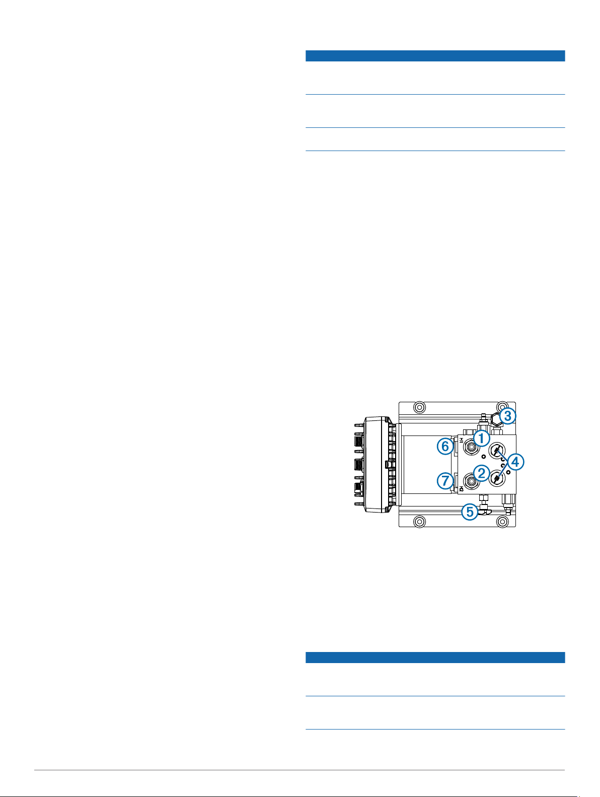
Pump Valves and Fittings
The pump can be connected to the hydraulic system using one
of two methods. The recommended three-connector method
uses only the H1 À and H2 Á fittings, with a T-connector
splitting the connection between the helm and cylinder. The
return line fitting  connects to only the helm. The check valves
should not be reconfigured if the boat is equipped with a
Ã
balanced cylinder. If the boat is equipped with an unbalanced
cylinder, the check valves must be reconfigured (Configuring the
Pump for an Unbalanced Cylinder). The bypass valve Ä is
opened only for hydraulic bleeding, and must be fully tightened
during normal operation.
If necessary, the C1 Å and C2 Æ fittings can be used with the
recommended three-connector installation instead of the H1 and
H2 fittings.
Alternatively, the pump can be installed using all five
connectors. This installation option uses the C1 and C2 fittings
to connect the pump to the cylinder and the H1 and H2 fittings to
connect the pump to the helm. This type of installation is not
recommended, because the pump cannot be removed for
service without disabling the steering system of the boat.
Configuring the Pump for an Unbalanced Cylinder
NOTICE
To avoid damage to the pump, keep all parts clean and free of
dust and debris while configuring the pump for an unbalancedcylinder steering system.
If you remove the check valves after bleeding the hydraulic
system, you must bleed it again. Reconfiguring the check valves
may introduce air into the hydraulic system.
2
If the boat has an unbalanced cylinder steering system, you
must configure the pump to work properly with the steering
system.
Remove the check valves À from the pump manifold.
1
Pull the pistons Á out of the pump manifold.
2
The pump is configured from the factory with the pistons in
the balanced configuration Â.
Remove the o-rings à from the pistons and discard them.
3
If you cannot easily pull the o-rings from the pistons, you may
need to cut them.
Re-insert the pistons into the pump manifold in the
4
unbalanced configuration Ä.
Insert the check valves into the pump manifold, and tighten
5
them.
Shadow Drive™ Mounting Considerations
• The Shadow Drive must be mounted horizontally and as level
as possible, with cable ties firmly securing it in place.
• The Shadow Drive must be mounted at least 305 mm (12 in.)
away from magnetic material, such as speakers and electric
motors.
• The Shadow Drive should be mounted closer to the helm
than to the pump.
• The Shadow Drive should be mounted lower than the helm,
but higher than the pump.
• The Shadow Drive must not be connected directly to the
fitting at the back of the helm. There must be a length of hose
between the fitting at the helm and the Shadow Drive.
• The Shadow Drive must not be connected directly to a
hydraulic T-connector in the hydraulic line. There must be a
length of hose between a T-connector and the Shadow Drive.
• In a single-helm installation, there must not be a T-connector
between the helm and the Shadow Drive.
• In a dual-helm installation, the Shadow Drive should be
installed between the pump and the hydraulic T-connector
that leads to the upper and lower helm, closer to the helm
than to the T-connector.
• The Shadow Drive must be installed in either the starboard
steering line or the port steering line.
The Shadow Drive must not be installed in either the return
line or the high-pressure line, if applicable.
Alarm Mounting and Connection Considerations
• The alarm should be mounted near the primary helm station.
• The alarm can be mounted under the dashboard.
• If needed, the alarm wires can be extended with 28 AWG
(0.08 mm2) wire.
NMEA 2000 Connection Considerations
• The CCU and the helm control must connect to a NMEA
2000 network.
• If your boat does not already have a NMEA 2000 network,
one can be built using the included NMEA 2000 cables and
connectors (Building a Basic NMEA 2000 Network for the
Autopilot System).
• To use the advanced features of the autopilot, optional
NMEA 2000 devices, such as a wind sensor, a water-speed
sensor, or a GPS device, can be connected to the NMEA
2000 network.
Power and Data Layout
WARNING
When connecting the power cable, do not remove the in-line
fuse holder. To prevent the possibility of injury or product
damage caused by fire or overheating, the appropriate fuse
must be in place as indicated in the product specifications. In
addition, connecting the power cable without the appropriate
fuse in place will void the product warranty.
Item Description Important Considerations
Helm control
À
CCU The CCU can be mounted in a non-submerged
Á
Helm control
Â
data cable
NMEA 2000
Ã
network
CCU cable To extend this cable to reach the ECU,
Ä
SmartPump This diagram does not show any hydraulic
Å
NMEA 2000
Æ
power cable
location near the center of the boat, in any
orientation (CCU Mounting and Connection
Considerations).
The CCU must be located away from sources of
magnetic interference.
This cable should be installed only if you are
connecting the autopilot to optional NMEA 0183
devices, such as a wind sensor, a water-speed
sensor, or a GPS device (NMEA 0183
Connection Considerations).
The helm control and the CCU must be
connected to a NMEA 2000 network using the
included T-connectors (NMEA 2000 Connection
Considerations).
If there is not an existing NMEA 2000 network on
your boat, you can build one using the supplied
cables and connectors (Building a Basic NMEA
2000 Network for the Autopilot System).
extensions (sold separately) may be necessary
(CCU Mounting and Connection
Considerations).
This cable connects to the alarm and the
Shadow Drive.
connections. Consult the hydraulic-layout
diagrams for details Hydraulic Layouts.
This cable should be installed only if you are
building a NMEA 2000 network. Do not install
this cable if there is an existing NMEA 2000
network on your boat.
The NMEA 2000 power cable must be
connected to a 9 to 16 Vdc power source.
3
Item Description Important Considerations
Pump power
Ç
cable
Alarm The alarm provides audible alerts from the
È
Shadow Drive The Shadow Drive must be installed properly in
É
The pump must be connected to a 12 to 24 Vdc
power source. To extend this cable, use the
correct wire gauge (Power Cable Extensions).
autopilot system, and should be installed near
the helm control (Installing the Alarm).
the hydraulic steering line, and connected to the
CCU cable (Installing the Shadow Drive).
Component Layout
Single-Helm Layout
Item Description Important Considerations
Helm control
À
12 to 24 Vdc
Á
battery
SmartPump
Â
CCU The CCU can be mounted in a non-submerged
Ã
NMEA 2000
Ä
network
The pump must be connected to a 12 to 24 Vdc
power source. To extend this cable, use the
correct wire gauge (Power Cable Extensions).
The NMEA 2000 power cable must be
connected to a 9 to 16 Vdc power source.
location near the center of the boat, in any
orientation (CCU Mounting and Connection
Considerations).
The CCU must be located away from sources of
magnetic interference.
The helm control and the CCU must be
connected to a NMEA 2000 network using the
included T-connectors (NMEA 2000 Connection
Considerations).
If there is not an existing NMEA 2000 network
on your boat, you can build one using the
supplied cables and connectors (Building a
Basic NMEA 2000 Network for the Autopilot
System).
NOTE: This diagram is for planning purposes only. If needed,
specific connection diagrams are included in the detailed
installation instructions for each component.
Hydraulic connections are not shown in this diagram.
Item Description Important Considerations
Helm control
À
SmartPump
Á
12 to 24 Vdc
Â
battery
CCU The CCU can be mounted in a non-submerged
Ã
NMEA 2000
Ä
network
The pump must be connected to a 12 to 24 Vdc
power source. To extend this cable, use the
correct wire gauge (Power Cable Extensions).
The NMEA 2000 power cable must be
connected to a 9 to 16 Vdc power source.
location near the center of the boat, in any
orientation (CCU Mounting and Connection
Considerations).
The CCU must be located away from sources of
magnetic interference.
The helm control and the CCU must be
connected to a NMEA 2000 network using the
included T-connectors (NMEA 2000 Connection
Considerations).
If there is not an existing NMEA 2000 network
on your boat, you can build one using the
supplied cables and connectors (Building a
Basic NMEA 2000 Network for the Autopilot
System).
Dual-Helm Layout Guidelines
Hydraulic Layouts
NOTICE
If the steering system in your boat does not match any of the
hydraulic layouts in this manual and you are unsure how to
install the pump, contact Garmin Product Support.
Before you start the pump installation, identify the type of
hydraulic steering system in your boat. Each boat is different,
and you must consider certain aspects of the existing hydraulic
layout before deciding where to mount the pump.
Important Considerations
• The pump must be reconfigured if the boat is equipped with
an unbalanced steering cylinder (Configuring the Pump for an
Unbalanced Cylinder).
• Garmin recommends using T-connectors to connect the
hydraulic lines to the pump.
• To allow for easy pump disabling and removal, Garmin
recommends installing shut-off valves in the hydraulic lines
between the pump manifold and T-connectors.
• Teflon® tape must not be used on any hydraulic fitting.
• An appropriate thread sealant should be used on all pipe
threads in the hydraulic system.
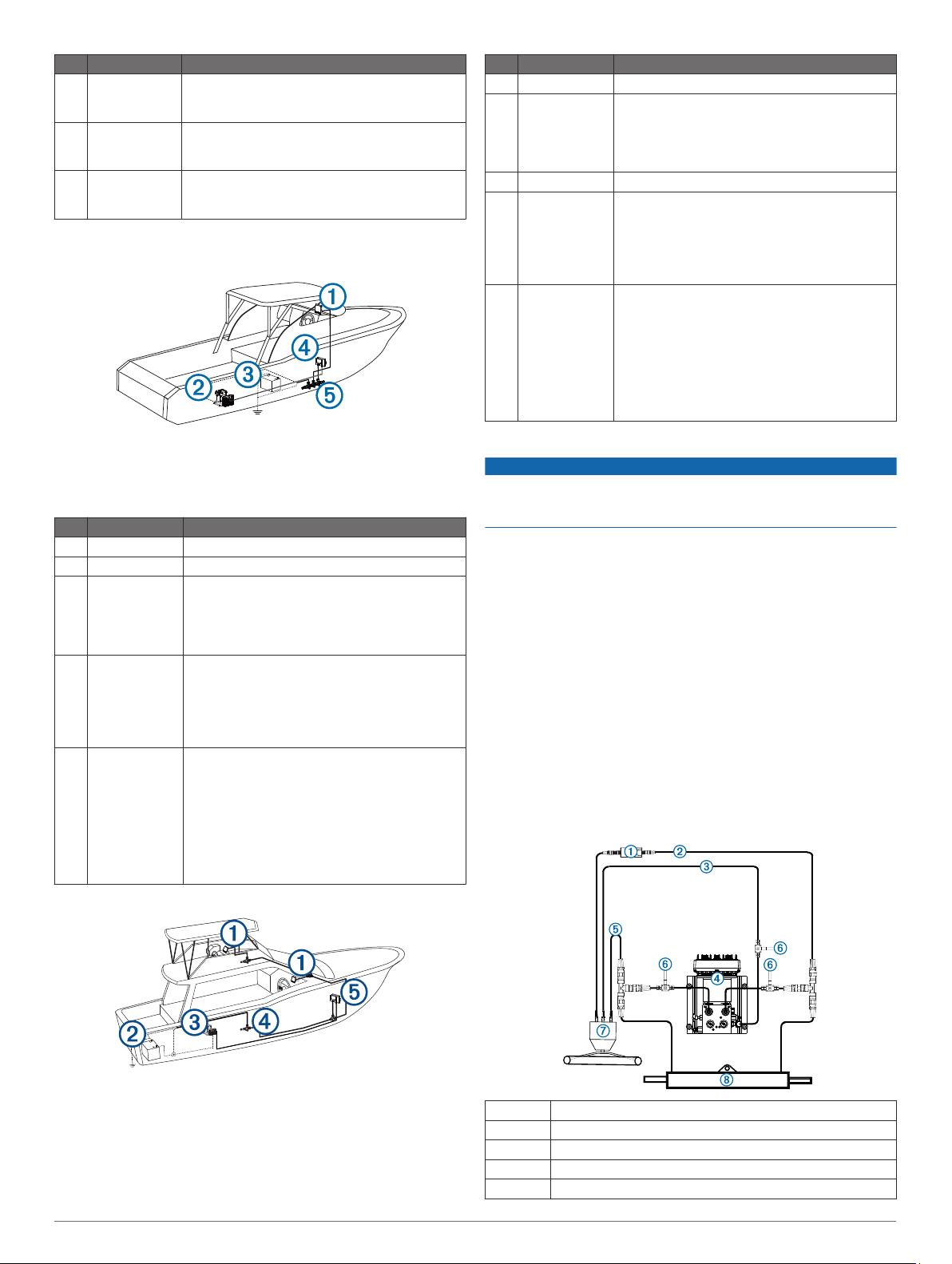
Single-Helm without Power Assist Layout
NOTE: This diagram is for planning purposes only. If needed,
specific connection diagrams are included in the detailed
installation instructions for each component.
Hydraulic connections are not shown in this diagram.
4
À
Á
Â
Ã
Ä
Shadow Drive
Starboard line
Return line
Pump
Port line
Å
L
T
R
P
L
T
R
P
L
T
R
P
Æ
Ç
Shut-off valves
Helm
Steering cylinder
Dual-Helm without Power Assist Layout
À
Á
Â
Ã
Ä
Å
Æ
Ç
È
Return line
Shadow Drive
Starboard line
Port line
Shut-off valves
Pump
Upper helm
Lower helm
Steering cylinder
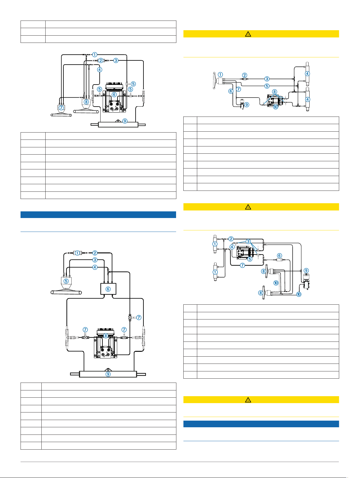
Single-Helm with Power Assist Layout
NOTICE
The pump must be installed between the cylinder and the
power-assist module to function correctly.
Single-Helm with Uflex® MasterDrive™ Layout
CAUTION
When installing the pump in a system with a Uflex MasterDrive,
do not cut the high-pressure line connecting the power unit to
the helm to avoid injury or property damage.
Helm
À
Shadow Drive
Á
Starboard line
Â
Steering cylinders
Ã
Port line
Ä
High pressure line - DO NOT CUT
Å
Return line
Æ
Shutoff valves
Ç
Uflex MasterDrive power unit
È
Pump
É
Dual-Helm with Uflex MasterDrive Layout
CAUTION
When installing the pump in a system with a Uflex MasterDrive,
do not cut the high-pressure line connecting the power unit to
the helm to avoid injury or property damage.
NOTE: Removal of the power assist-module may be necessary
to gain access to the fittings, hoses, and bleed-tee fitting.
À
Á
Â
Ã
Ä
Å
Æ
Ç
È
Shadow Drive
Starboard line
Port line
Return line
Helm
Power-assist module
Shut-off valves
Pump
Steering cylinder
Steering cylinders
À
Port line
Á
Shutoff valves
Â
Return line
Ã
Pump
Ä
Shadow Drive
Å
Starboard line
Æ
Helms
Ç
Uflex MasterDrive power unit
È
High pressure line - DO NOT CUT
É
Installation Procedures
CAUTION
Always wear safety goggles, ear protection, and a dust mask
when drilling, cutting, or sanding.
NOTICE
When drilling or cutting, always check what is on the opposite
side of the surface.
After you have planned the autopilot installation on your boat
and satisfied all of the mounting and wiring considerations for
5
 Loading...