

GHP™ Reactor Steer-
by-Wire
Installation Instructions
Important Safety Information
WARNING
See the Important Safety and Product Information guide in the
product box for product warnings and other important
information.
You are responsible for the safe and prudent operation of your
vessel. The autopilot is a tool that enhances your capability to
operate your boat. It does not relieve you of the responsibility of
safely operating your boat. Avoid navigational hazards and
never leave the helm unattended.
Always be prepared to promptly regain manual control of your
boat.
Learn to operate the autopilot on calm and hazard-free open
water.
Use caution when operating the autopilot near hazards in the
water, such as docks, pilings, and other boats.
CAUTION
When in use, beware of hot motor and solenoid components
and the risk of entrapment from moving parts.
Failure to install and maintain this equipment in accordance with
these instructions could result in damage or injury.
NOTICE
To avoid damage to your boat, the autopilot system should be
installed by a qualified marine installer. Specific knowledge of
hydraulic steering componentry and marine electrical systems is
required for proper installation.
Installation Preparation
The autopilot system consists of multiple components. You
should familiarize yourself with all of the component mounting
and connection considerations before beginning installation. You
must know how the components operate together in order to
correctly plan the installation on your boat.
You can consult the layout diagrams (Power and Data Layout)
to help understand the mounting and connection considerations.
You should lay out all of the components on the boat as you
plan the installation to make sure your cables will reach each
component. If needed, extension cables (sold separately) for
various components are available from your Garmin® dealer or
from www.garmin.com.
You should record the serial number of each component for
registration and warranty purposes.
Tools Needed
• Safety glasses
• Drill and drill bits
• 90 mm (3.5 in.) hole saw or a rotary cutting tool
• Wire cutters/strippers
• Phillips and flat screwdrivers
• Cable ties
• Waterproof wire connectors (wire nuts) or heat-shrink tubing
and a heat gun
• Marine sealant
• Portable or handheld compass (to test for magnetic
interference)
• Anti-seize lubricant (optional)
NOTE: Mounting screws are provided for the main components
of the autopilot system. If the provided screws are not
appropriate for the mounting surface, you must provide the
correct types of screws.
Mounting and Connection Considerations
The autopilot components connect to each other and to power
using the included cables. Ensure that the correct cables reach
each component and that each component is in an acceptable
location before mounting or wiring any components.
Helm Control Mounting Considerations
NOTICE
This device should be mounted in a location that is not exposed
to extreme temperatures or conditions. The temperature range
for this device is listed in the product specifications. Extended
exposure to temperatures exceeding the specified temperature
range, in storage or operating conditions, may cause device
failure. Extreme-temperature-induced damage and related
consequences are not covered by the warranty.
The mounting surface must be flat to avoid damaging the device
when it is mounted.
Using the included hardware and template, you can flush mount
the device in the dashboard. If you want to mount the device
using an alternative method where it appears flat with the front
of the dashboard, you must purchase a flat-mount kit
(professional installation recommended) from your Garmin
dealer.
When selecting a mounting location, observe these
considerations.
• The mounting location should be at or below eye level to
provide optimal viewing as you operate your vessel.
• The mounting location should allow easy access to the keys
on the device.
• The mounting surface must be strong enough to support the
weight of the device and protect it from excessive vibration or
shock.
• To avoid interference with a magnetic compass, the device
should not be installed closer to a compass than the
compass-safe distance value listed in the product
specifications.
• The area behind the mounting surface must allow room for
the routing and connection of the cables.
Helm Control Connection Considerations
• The helm control must connect to the NMEA 2000® network.
• Optional NMEA® 0183 devices, such as wind sensors, waterspeed sensors, or GPS devices can be connected to the
helm control using a data cable (NMEA 0183 Connection
Considerations).
May 2015
Printed in Taiwan 190-01766-02_0B
CCU Mounting and Connection Considerations
• The CCU is the primary sensor of the GHP Reactor Steer-byWire autopilot system. For best performance, observe these
considerations when selecting a mounting location.
◦ A handheld compass should be used to test for magnetic
interference in the area where the CCU is to be mounted.
If the needle on a handheld compass moves when you
hold it where you intend to mount the CCU, magnetic
interference is present. You must choose another location
and test again.
◦ The CCU should be mounted on a rigid surface for best
performance.
◦ Although the CCU can be installed in any orientation on
your boat, you can avoid the step of defining north in the
setup procedure by meeting all of these considerations
when selecting a mounting location (optional).
◦ The connectors on the CCU must point toward the
bow.
◦ The base of the CCU must be at a right angle to the roll
and pitch axis of the boat.
◦ The CCU must be located near the center of rotation of
the boat, slightly toward the front, if necessary.
• The CCU cable connects the CCU to the steering system and
is 3 m (9 ft.) long.
◦ If the CCU cannot be mounted within 3 m (9 ft.) of the
steering system, extension cables are available from your
local Garmin dealer or at www.garmin.com.
◦ This cable must not be cut.
Finding the Best Mounting Location
Create a list of all suitable mounting locations for the CCU
1
where no iron, magnets, or high-current wires are located
within 60 cm (2 ft.).
A large magnet, such as a subwoofer-speaker magnet should
be no closer than 1.5 m (5 ft.) to these locations.
Locate the center of rotation of the boat, and measure the
2
distance between the center of rotation and each of the
suitable mounting locations you listed in step 1.
Select the location closest to the center of rotation.
3
If more than one location is approximately the same distance
from the center of rotation, you should select the location that
best meets these considerations.
• The best location is closest to the centerline of the boat.
• The best location is lower in the boat.
• The best location is slightly forward in the boat.
Alarm Mounting and Connection Considerations
• The alarm should be mounted near the primary helm station.
• The alarm can be mounted under the dashboard.
• If needed, the alarm wires can be extended with 28 AWG
(0.08 mm2) wire.
NMEA 2000 Connection Considerations
• The CCU and the helm control must connect to a NMEA
2000 network.
• If your boat does not already have a NMEA 2000 network,
one can be built using the included NMEA 2000 cables and
connectors (Building a Basic NMEA 2000 Network for the
Autopilot System).
• To use the advanced features of the autopilot, optional
NMEA 2000 devices, such as a wind sensor, a water-speed
sensor, or a GPS device, can be connected to the NMEA
2000 network.
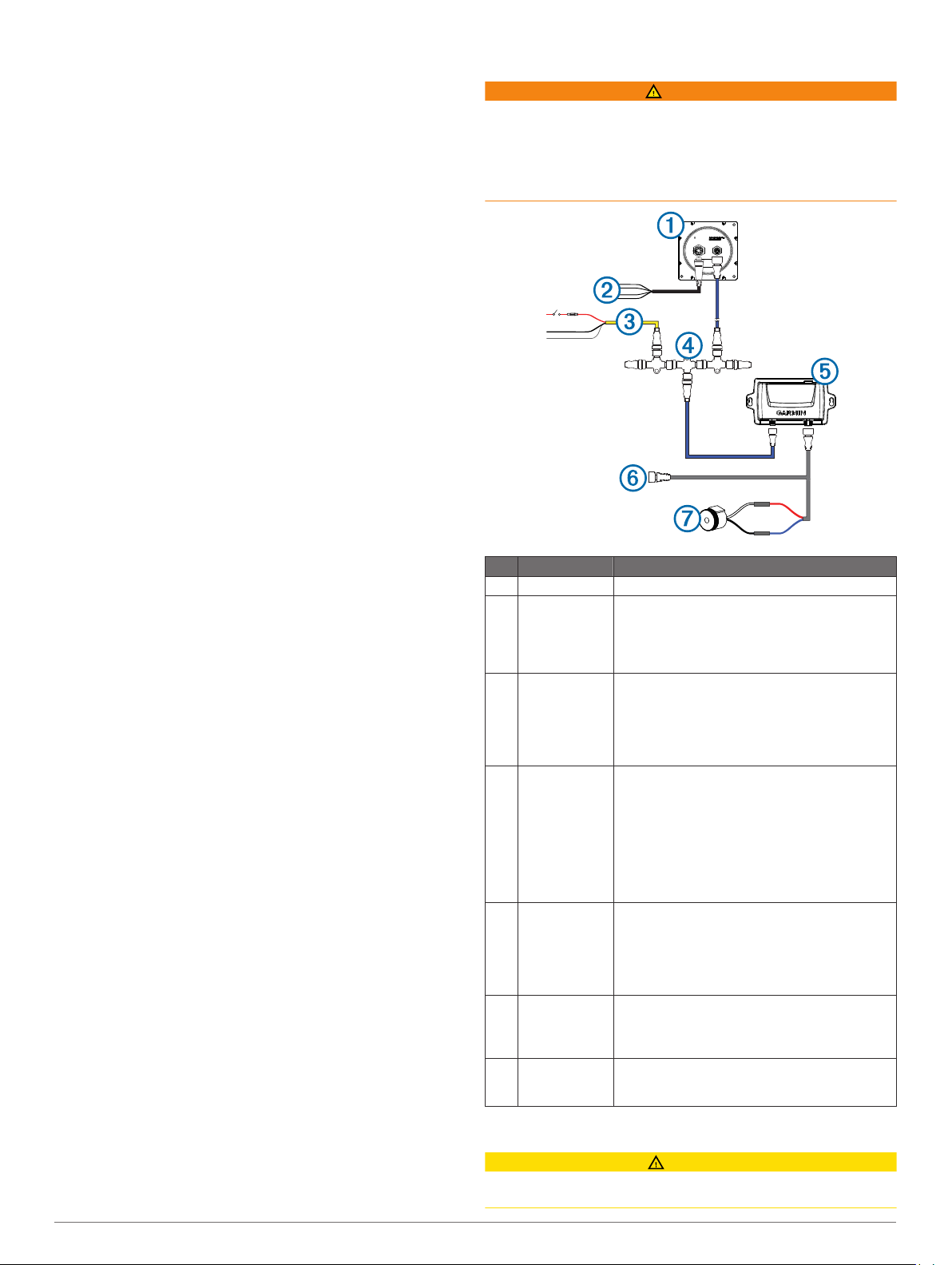
Power and Data Layout
WARNING
When connecting the power cable, do not remove the in-line
fuse holder. To prevent the possibility of injury or product
damage caused by fire or overheating, the appropriate fuse
must be in place as indicated in the product specifications. In
addition, connecting the power cable without the appropriate
fuse in place will void the product warranty.
Item Description Important Considerations
Helm control
À
Helm control
Á
data cable
NMEA 2000
Â
power cable
NMEA 2000
Ã
network
CCU The CCU can be mounted in a non-submerged
Ä
Engine
Å
connection
Alarm The alarm provides audible alerts from the
Æ
This cable should be installed only if you are
connecting the autopilot to optional NMEA 0183
devices, such as a wind sensor, a water-speed
sensor, or a GPS device (NMEA 0183
Connection Considerations).
This cable should be installed only if you are
building a NMEA 2000 network. Do not install
this cable if there is an existing NMEA 2000
network on your boat.
The NMEA 2000 power cable must be
connected to a 9 to 16 Vdc power source.
The helm control and the CCU must be
connected to a NMEA 2000 network using the
included T-connectors (NMEA 2000 Connection
Considerations).
If there is not an existing NMEA 2000 network
on your boat, you can build one using the
supplied cables and connectors (Building a
Basic NMEA 2000 Network for the Autopilot
System).
location near the center of the boat, in any
orientation (CCU Mounting and Connection
Considerations).
The CCU must be located away from sources of
magnetic interference.
The CCU connects either to the engine control
directly or through an adapter. Additional
instructions are provided with the adapter, if
applicable.
autopilot system, and should be installed near
the helm control (Installing the Alarm).
Installation Procedures
CAUTION
Always wear safety goggles, ear protection, and a dust mask
when drilling, cutting, or sanding.
2
NOTICE
When drilling or cutting, always check what is on the opposite
side of the surface.
After you have planned the autopilot installation on your boat
and satisfied all of the mounting and wiring considerations for
your particular installation, you can begin mounting and
connecting the components.
Helm Control Installation
You must Install the helm control by flush-mounting it in the
dashboard near the helm and connecting it to a NMEA 2000
network.
To use advanced features of the autopilot, optional NMEA 2000compatible or NMEA 0183-compatible devices, such as a wind
sensor, water-speed sensor, or GPS device, can be connected
to the NMEA 2000 network or connected to the helm control
through NMEA 0183.
Mounting the Helm Control
NOTICE
If you are mounting the device in fiberglass, when drilling the
four pilot holes, it is recommended to use a countersink bit to
drill a clearance counterbore through only the top gel-coat layer.
This will help to avoid any cracking in the gel-coat layer when
the screws are tightened.
Stainless-steel screws may bind when screwed into fiberglass
and overtightened. Garmin recommends applying an anti-seize
lubricant to the screws before installing them.
Before you can mount the helm control, you must select a
mounting location (Helm Control Mounting Considerations).
Trim the flush-mount template and ensure it fits in the
1
selected mounting location.
The flush-mount template is included in the helm control
product box.
Secure the template to the selected mounting location.
2
If you plan to cut the hole with a rotary cutting tool instead of
3
a 90 mm (3.5 in.) hole saw, use a 10 mm (3/8 in.) drill bit to
drill a pilot hole as indicated on the template to begin cutting
the mounting surface.
Using the hole saw or rotary cutting tool, cut the mounting
4
surface along the inside of the dashed line indicated on the
template.
If necessary, use a file and sandpaper to refine the size of
5
the hole.
Place the helm control into the cutout to confirm that the four
6
mounting holes on the template are in the correct locations.
If the mounting holes are not correct, mark the correct
7
locations of the four mounting holes.
Remove the helm control from the cutout.
8
Drill the four 2.8 mm (7/64 in.) pilot holes.
9
If you are mounting the helm control in fiberglass, you should
use a countersink bit as advised in the notice.
Remove the remainder of the template.
10
Place the included gasket on the back of the device.
11
You can apply marine sealant around the gasket to prevent
leakage behind the dashboard (optional).
Place the helm control into the cutout.
12
Securely fasten the helm control to the mounting surface
13
using the supplied screws.
If you are mounting the helm control in fiberglass, you should
use an anti-seize lubricant as advised in the notice.
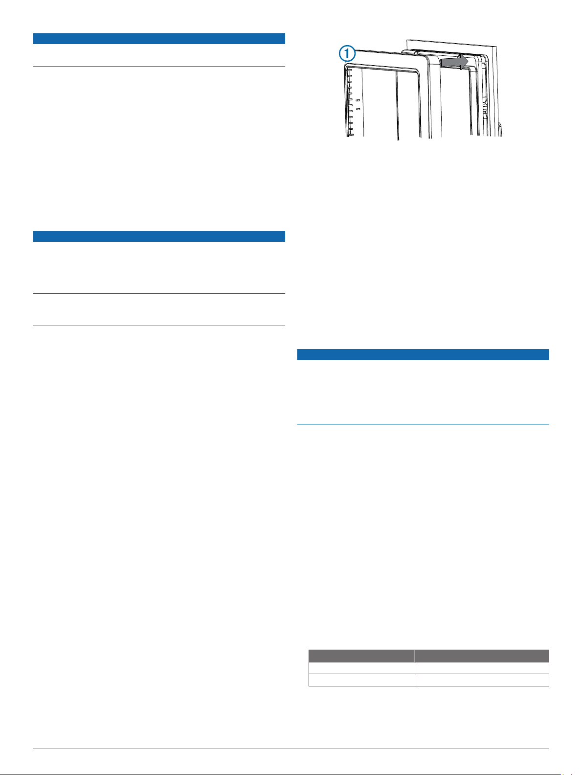
Snap the decorative bezel À into place.
14
Mounting the CCU
Determine the mounting location.
1
Using the CCU as a template, mark the two pilot hole
2
locations on the mounting surface.
Using a 3 mm (1/8 in.) bit, drill the pilot holes.
3
Use the included screws to attach the CCU to the mounting
4
surface.
Connecting the CCU
Route the connector end of the CCU cable to the steering
1
system connection or CAN bus and make the connection.
Route the orange and blue wires from the bare-wire portion
2
of the CCU cable to the location where you plan to install the
alarm (Installing the Alarm).
If the cable is not long enough, extend the appropriate wires
with 0.08 mm2 (28 AWG) wire.
Connecting to the Steering System of the Boat
NOTICE
Do not connect the steering controller cable to a NMEA 2000
network.
The autopilot requires a powered CAN bus to communicate with
the steering controller. Ensure the steering controller CAN bus is
properly powered and terminated. Consult the boat
manufacturer if needed.
The steering controller cable allows the autopilot system to
communicate with the steering system of the boat through a
steering controller CAN bus. Additional instructions are supplied
with the CAN bus.
If needed, consult the manufacturer of your boat for assistance
locating the steering-system access.
Locate the steering-system access for your boat.
1
Connect the steering controller cable from the CCU to the
2
steering system through the included steering controller CAN
bus.
NOTE: If necessary, the steering controller cable can be
extended using a NMEA 2000 extension cable.
Installing the Alarm
Before you can mount the alarm, you must select a mounting
location (Alarm Mounting and Connection Considerations).
Route the alarm cable to the bare-wire end of the CCU cable.
1
If the cable is not long enough, extend the appropriate wires
with 28 AWG (0.08 mm2) wire.
Connect the cables, based on this table.
2
Alarm Wire Color CCU Cable Wire Color
White (+) Orange (+)
Black (-) Blue (-)
Solder and cover all bare-wire connections.
3
Secure the alarm with cable ties or other mounting hardware
4
(not included).
3
 Loading...