

Garmin GHP Reactor Instructions
GHP® Reactor™ Steer-by-Wire Yamaha® Gateway Addendum
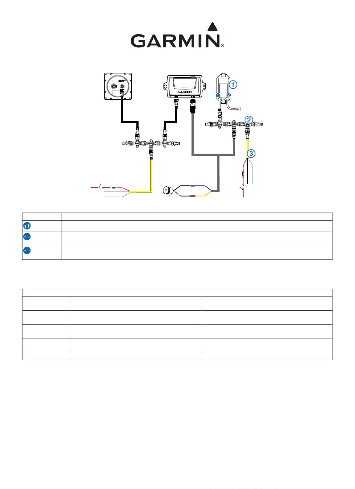
When installing the Garmin autopilot on your boat, refer to this diagram to connect the autopilot to the steering system through this gateway.
Item Description
➊
➋
➌
Autopilot gateway. This connects to the steering system of your boat.
Gateway data bus. The included T-connectors must be assembled as shown to properly communicate with the autopilot
gateway.
The included power cable must be connected to a 9–24 Vdc power source for the autopilot to communicate with the gateway.
When the Autopilot LED
➊
on the gateway adapter is solid, the data bus is correctly connected to power.
Gateway Troubleshooting
If the autopilot does not appear to be correctly communicating with the steering system of the boat, you should observe the Diagnostic LED ➋ on the
gateway adapter.
LED Behavior Description Troubleshooting
Off The gateway is not receiving power from the steering system. The gateway may not be connected correctly to the steering
Solid The gateway is receiving power from the steering system, but
is not receiving communication from either side.
Flashing double-blink The gateway is receiving data from the steering system, but
not from the autopilot system.
Flashing triple-blink The gateway is receiving data from the autopilot, but not from
the steering system.
Flashing The gateway is properly receiving and transmitting data.
system.
Check all connections.
Check all autopilot connections.
Check all steering-system connections.
GHP® Reactor™ pour direction à commande électrique (SBW) - Passerelle Yamaha® -
Supplément
Lors de l'installation du pilote automatique Garmin sur votre bateau, reportez-vous à ce schéma pour connecter le pilote automatique au système de
direction par le biais de cette passerelle.
Elément Description
➊
➋
➌
Résolution des problèmes de passerelle
Si le pilote automatique ne semble pas bien communiquer avec le système de direction du bateau, observez les voyants LED de diagnostic ➋ sur
l'adaptateur de la passerelle.
Comportement du
voyant LED
Eteint La passerelle n'est pas alimentée via le système de direction. La passerelle n'est peut-être pas correctement connectée au
Fixe La passerelle est alimentée via le système de direction mais
Clignotement double La passerelle reçoit les données depuis le système de
Clignotement triple La passerelle reçoit les données depuis le pilote automatique
Clignotement La passerelle reçoit et transmet les données correctement.
Passerelle de pilote automatique. Se connecte au système de direction de votre bateau.
Bus de données de la passerelle. Les connecteurs en T fournis doivent être assemblés comme indiqué pour permettre une
bonne communication avec la passerelle du pilote automatique.
Le câble d'alimentation fourni doit être connecté à une source d'alimentation 9–24 V c.c. pour que le pilote automatique puisse
communiquer avec la passerelle.
Lorsque le voyant LED
est correctement connecté à l'alimentation.
Description Dépannage
la communication est défaillante.
direction mais pas depuis le système de pilote automatique.
mais pas depuis le système de direction.
➊
du pilote automatique s'allume sur l'adaptateur de la passerelle, cela signie que le bus de données
système de direction.
Vériez tous les branchements.
Vériez tous les branchements du pilote automatique.
Vériez tous les branchements du système de direction.
GHP® Reactor™ Steer-by-Wire Gateway Yamaha® Appendice
Durante l’installazione dell’autopilota Garmin, consultare questo diagramma per collegare l’autopilota alla timoneria tramite questo gateway.
Elemento Descrizione
➊
➋
➌
Risoluzione dei problemi relativi al gateway
Se l’autopilota sembra non comunicare correttamente con la timoneria dell’imbarcazione, osservare il LED di diagnostica ➋ sull’adattatore del gateway.
Comportamento del
LED
Spento Il gateway non sta ricevendo alimentazione dalla timoneria. Il gateway potrebbe non essere collegato correttamente alla
Fisso Il gateway sta ricevendo alimentazione dalla timoneria, ma
Lampeggiamento
doppio
Lampeggiamento
triplo
Lampeggiante Il gateway sta ricevendo e trasmettendo dati correttamente.
Gateway dell'autopilota. Si collega alla timoneria dell'imbarcazione.
Bus dati del gateway. I connettori a T inclusi devono essere assemblati come indicato per comunicare correttamente con il
gateway dell'autopilota.
Il cavo di alimentazione incluso deve essere collegato a una fonte di alimentazione da 9–24 V cc afnché l'autopilota possa
comunicare con il gateway.
Quando il LED dell'autopilota
Descrizione Risoluzione dei problemi
non sta ricevendo comunicazioni dall'altra parte.
Il gateway sta ricevendo dati dalla timoneria, ma non dal
sistema autopilota.
Il gateway sta ricevendo dati dall'autopilota, ma non dalla
timoneria.
➊
sull'adattatore del gateway è sso, il bus dati è correttamente collegato all'alimentazione.
timoneria.
Vericare tutti i collegamenti.
Vericare tutti i collegamenti dell'autopilota.
Vericare tutti i collegamenti della timoneria.
 Loading...