

Page 1
GHP™ 10 Marine Autopilot System Installation Instructions
To obtain the best possible performance and to avoid damage to your boat, install your GHP 10 marine autopilot system according to
the following instructions. Read all installation instructions before proceeding with the installation. If you experience difculty
during the installation, contact Garmin Product Support, or seek the advice of a professional installer.
Product Registration
Help us better support you by completing our online registration today! Connect to our Web site at http://my.garmin.com. Keep the
original sales receipt, or a photocopy, in a safe place.
For future reference, write the serial number assigned to each component of your GHP 10 system in the spaces provided on page 2.
The serial numbers are located on a sticker on each component.
Contact Garmin
Contact Garmin if you have any questions while using your GHP 10. In the USA contact Garmin Product Support by phone: (913)
397-8200 or (800) 800-1020, or go to www.garmin.com/support/.
In Europe, contact Garmin (Europe) Ltd. at +44 (0) 870.8501241 (outside the UK) or 0808 2380000 (within the UK).
Warnings
You are responsible for the safe and prudent operation of your vessel. The GHP 10 is a tool that will enhance your capability
•
to operate your boat. It does not relieve you from the responsibility of safely operating your boat. Avoid navigational hazards and
never leave the helm unattended.
Always be prepared to promptly regain manual control of your boat.
•
Learn to operate the GHP 10 on calm and hazard-free open water.
•
Use caution when operating the GHP 10 at high speeds near hazards in the water, such as docks, pilings, and other boats.
•
See the Important Safety and Product Information guide in the product box for product warnings and other important
•
information.
Cautions
Always wear safety goggles, ear protection, and a dust mask when drilling, cutting, or sanding.
•
When drilling or cutting, always check the opposite side of the surface. Be aware of fuel tanks, electrical cables, and hydraulic
•
hoses.
June 2008 190-00894-02 Rev. A Printed in Taiwan
Page 2
GHP 10 Package Contents and Tools Needed
The GHP 10 autopilot system consists of multiple components. Familiarize yourself with all of the components before beginning
installation. You must know how the components operate together in order to correctly plan the installation on your boat.
As you familiarize yourself with the GHP 10 components, conrm that your package includes the following items. All the components
except for the hydraulic pump are included in the GHP 10 core box. The pump is packaged separately. If any parts are missing, contact
your Garmin dealer immediately.
The Main Components
The GHP 10 autopilot system consists of ve main components: the Electronic Control Unit (ECU), the Course Computer Unit
(CCU), a hydraulic pump, the Shadow Drive
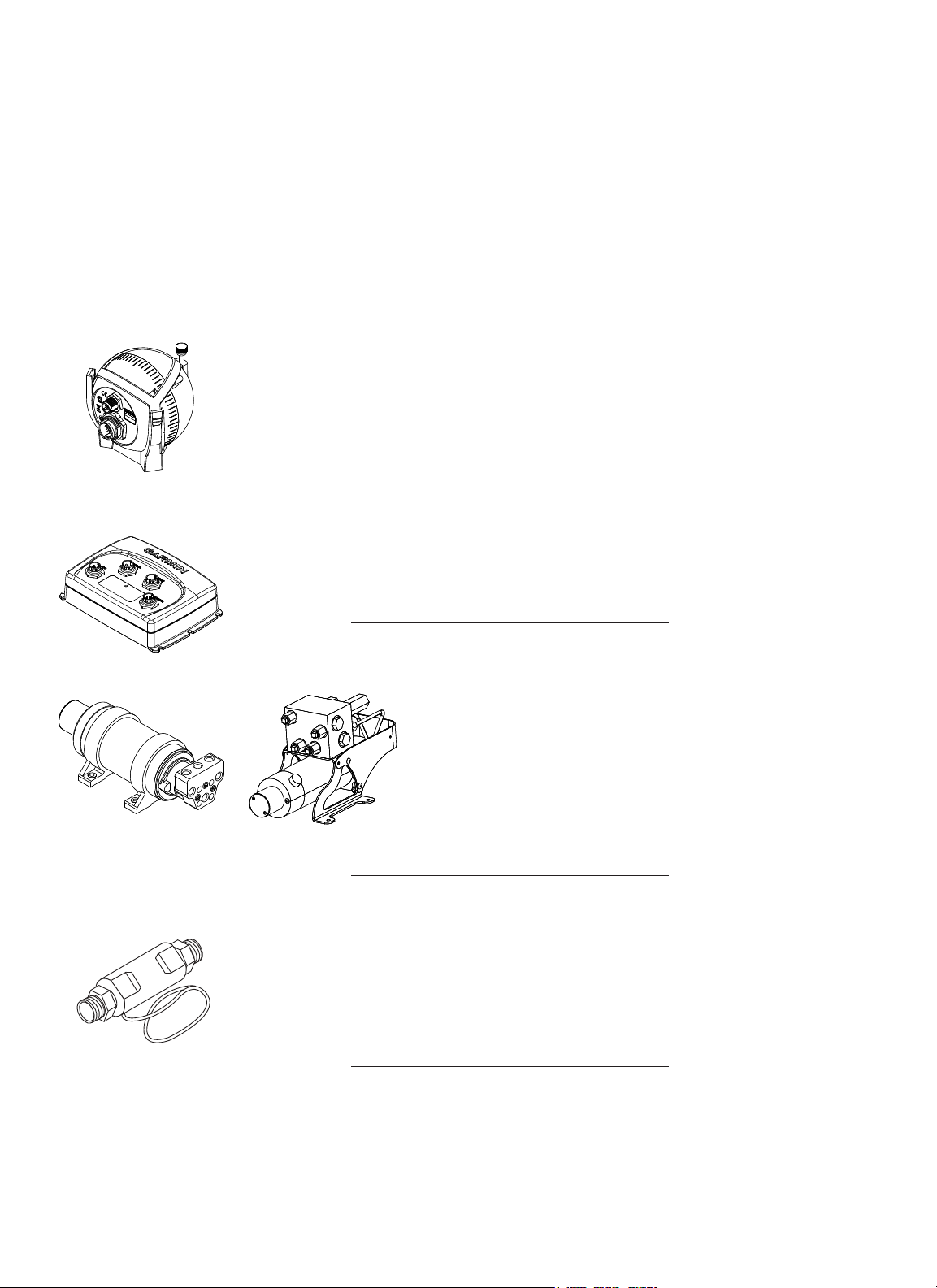
The Course Computer Unit (CCU)
The CCU acts as the “brain” of the GHP 10. The CCU contains the sensory equipment used to determine
heading and engine speed. The CCU connects to the Electronic Control Unit (ECU), to the GHC 10, and
to the tachometer of your boat with a single cable. The CCU also connects to a NMEA 2000® network to
communicate with the GHC 10, and to an optional NMEA 2000-compatible GPS device.
Garmin part number: 010-11052-00
Serial number
The Electronic Control Unit (ECU)
The ECU connects to the CCU and to the pump. The ECU controls the pump based on information from
the CCU. The ECU powers both the CCU and the pump.
™
, and the GHC™ 10 user control interface.
Garmin part number: 010-11053-00
Serial number
The Hydraulic Pump (and motor)
1.2 L/2.0 L Pump1.2 L/2.0 L Pump
Serial number
2.1 L Pump2.1 L Pump
The Shadow Drive
The Shadow Drive is a sensor you install in the hydraulic steering lines of your boat. While the GHP 10 is
engaged, the Shadow Drive temporarily disengages the autopilot when you manually take control of the
helm. When you manually steer the boat in a straight line again, the Shadow Drive allows the autopilot to
resume control.
Garmin part number: 010-11054-00
The hydraulic pump (and motor) steers your boat by interacting with the
hydraulic steering system, based on commands you enter using the GHC
10. The pump is not included in the GHP 10 core package box because
the type of pump you use with your GHP 10 is determined by the engine
and steering system of your boat. The pump is in a separate box.
Garmin part numbers: 010-11097-00 (2.0 L pump), 010-11098-00
(1.2 L pump), and 010-11099-00 (2.1 L pump)
Serial number
2 GHP 10 Marine Autopilot System Installation Instructions
Page 3
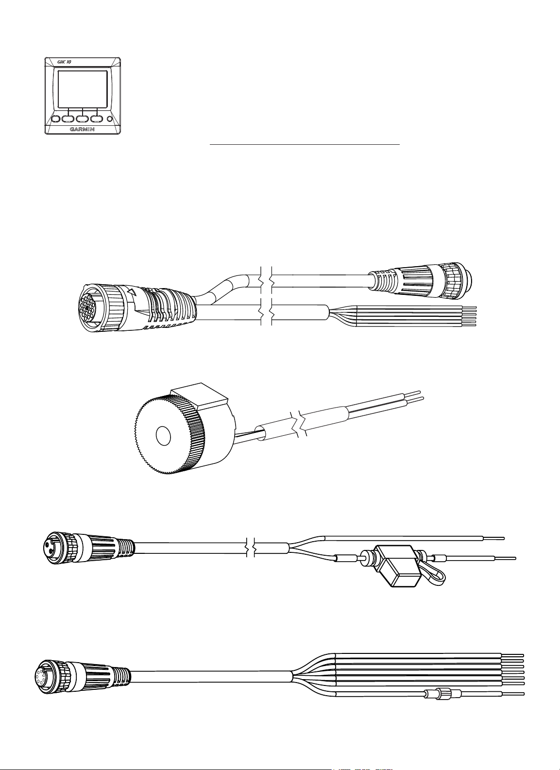
The GHC 10
Use the GHC 10 to operate the GHP 10 autopilot system. Using the GHC 10, you engage and steer
the GHP 10. You also set up and customize the GHP 10 using the GHC 10. The GHC 10 connects to
a NMEA 2000 network to communicate with the CCU and with an optional NMEA 2000-compatible
GPS device (to use waypoint and route information). If a NMEA 2000-compatible GPS device is not
available, you can wire the GHC 10 to an optional NMEA 0183-compatible GPS device instead.
Garmin part number: 010-00688-00
Serial number
Cables and Connectors
The GHP 10 autopilot system contains multiple cables. These cables connect the components to power, to each other, to an alarm, and
to optional devices such as a NMEA 0183-compatible GPS device.
CCU/ECU Interconnect Cable
This cable connects the CCU to the ECU. A portion of this cable contains color-coded wires with bare ends. These wires connect the
CCU to the tachometer of your boat, to the Shadow Drive, and to the alarm. (Garmin part number: 010-11055-00)
The Alarm
The alarm is wired to the CCU and provides audible alerts from the GHP 10. See page 18. (Garmin part number: 010-11056-00)
ECU Power Cable
This cable powers the ECU. Wire this to the battery of your boat as one of the last connections made in the GHP 10 installation.
See page 24. (Garmin part number: 010-11057-00)
GHC 10 Power/Data Cable
This cable is included in the GHC 10 box. Wire this cable to the battery of your boat as one of the last connections made in the GHP
10 installation. This cable is used to wire to an optional NMEA 0183-compatible GPS device. See page 20.
(Garmin part number: 320-00023-07)
3GHP 10 Marine Autopilot System Installation Instructions
Page 4
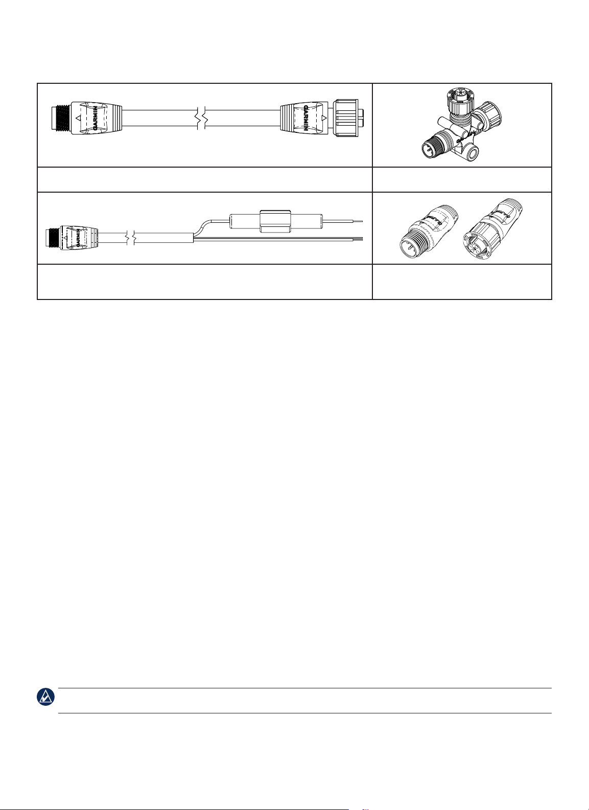
NMEA 2000 Cables and Connectors
The NMEA 2000 cables connect the CCU and the GHC 10 to the NMEA 2000 network. Use the NMEA 2000 power cable and two
terminators to create a NMEA 2000 network on your boat if one does not exist. For more information on NMEA 2000, see page 21.
NMEA 2000 drop cable, 6 ft. (2 m) (×2), Garmin part number: 320-00387-00 NMEA 2000 T-connector (×3), Garmin part
number: 330-00563-00
NMEA 2000 power cable, Garmin part number: 320-00389-00 (×1) NMEA 2000 terminators, male Garmin part
number: 330-00564-00 (×1); female Garmin part
number: 330-00565-00 (×1)
CCU/ECU Interconnect Extension Cables (Not Included)
When installing the GHP 10 system, you may need to mount the CCU farther than 91/2 ft. (3 m) from the ECU. Garmin offers two
optional extension cables for purchase if this is necessary, a 161/2 ft. (5 m) cable (Garmin part number 010-11156-00) and a 49 ft.
(15 m) cable (Garmin part number: 010-11156-01). Contact your local Garmin dealer or Garmin Product Support for ordering
information.
Tools Needed
Safety glasses
•
Drill and drill bits
•
Jigsaw or 317/32 in. (90 mm) hole saw
•
Center punch and hammer
•
Scissors
•
Wrenches
•
Pliers
•
Wire cutters/stripers
•
File and sandpaper
•
Phillips head and athead screwdrivers
•
Cable ties
•
Waterproof wire connectors (wire nuts)
•
Surface-specic mounting hardware (screws)
•
Marine sealant
•
Anti-seize lubricant (optional)
•
Compass (to test for magnetic interference)
•
NOTE: Mounting screws are provided for the GHC 10, for the CCU, for the ECU, and for the pump. If the provided screws are not
appropriate for the mounting surface, you will need to provide the correct types of screws.
Hydraulic supplies
•
Hose cutter
◦
Additional hydraulic hose with machine-crimped or
◦
eld-replaceable ttings that have a minimum rating of
1000 lb/in
Additional hydraulic uid
◦
Rags
◦
Thread sealant (Loctite® Pro Lock Tight® multipurpose
◦
2
anaerobic gel, part number 51604, or equivalent)
Helm/hydraulic bleeding equipment
◦
4 GHP 10 Marine Autopilot System Installation Instructions
Page 5
Installation Preparation
Before installing the GHP 10 autopilot system, it is important for you to completely understand where all the components will be
located on your boat. Temporarily place all the components where you plan to install them. Ensure that all cables and hydraulic hoses
can reach the necessary components before mounting any components.
Hydraulic Considerations – 2.0 L and 1.2 L Pumps
Different boats have different hydraulic considerations you must examine before mounting the pump or cutting any hoses. Before
starting the hydraulic installation, verify the type of hydraulic steering in your boat, and where to install the appropriate type of pump.
CAUTION: If the hydraulic steering of your boat does not match the hydraulic layouts in this manual, contact Garmin Product Support.
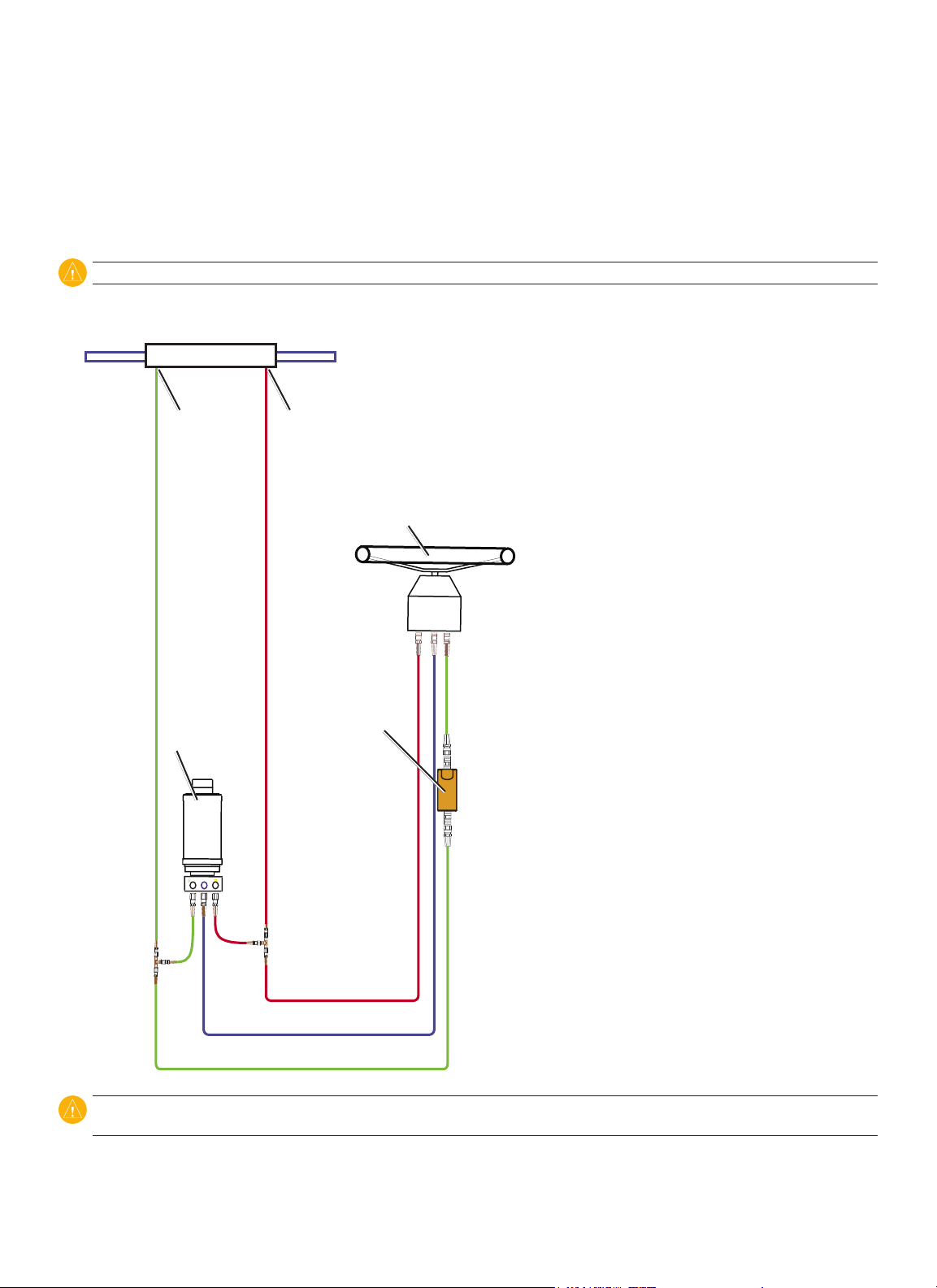
Single-Helm Boats (Without Power Assist)
Balanced cylinder
2.0 L/1.2 L pump
(and motor)
Port ttingStarboard tting
Shadow drive
Helm
P R S
Notes:
2.0 L/1.2 L pump (and motor):
•
An unbalanced cylinder requires an
◦
unbalanced valve on the pump (See page 30)
Mount the pump horizontally if possible. Do
◦
not mount the pump vertically with the pump
end (hydraulic connections) down.
Shadow Drive
•
Mount the Shadow Drive horizontally and as
◦
level as possible.
Install the Shadow Drive in either the port or
◦
the starboard hydraulic steering line.
Always install a length of hose between the
◦
helm and the Shadow Drive.
Do not install the Shadow Drive directly to
◦
the helm.
Install the Shadow Drive between the pump
◦
and the helm.
Do not install the Shadow Drive between
◦
the pump and the cylinder.
Port line
Return line
Starboard line
CAUTION: Do not turn the system on until you bleed all the air from the helm, the Shadow Drive, the pump, and all the hydraulic lines.
See page 24.
5GHP 10 Marine Autopilot System Installation Instructions
Page 6
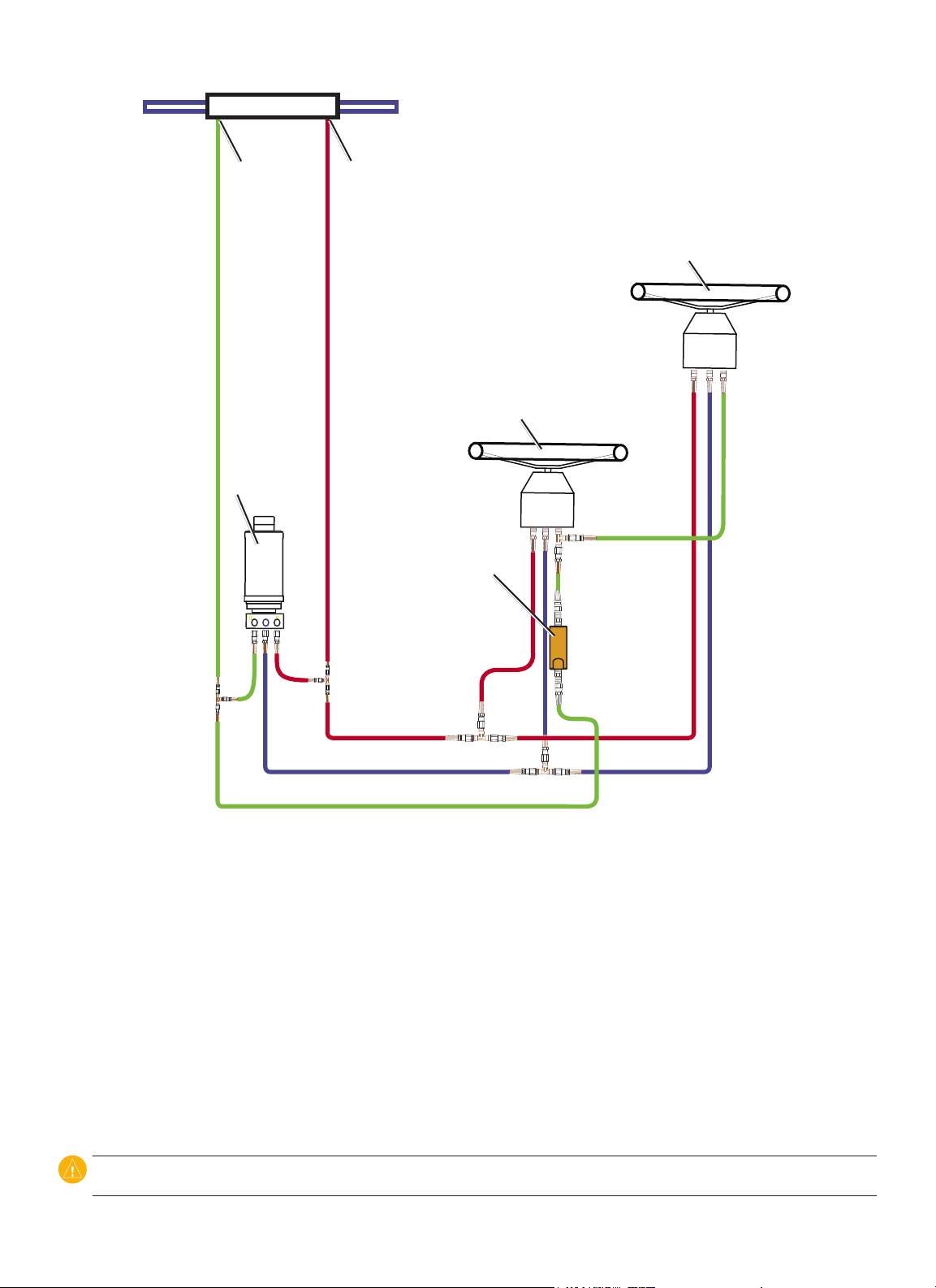
Dual-Helm Boats
Balanced cylinder
Starboard tting
2.0 L/1.2 L pump
(and motor)
Port tting
Upper helm
P R S
Lower helm
P R S
Shadow drive
Port line
Return line
Starboard line
Notes:
2.0 L/1.2 L pump (and motor):
•
An unbalanced cylinder requires an unbalanced valve on the pump (See page 30)
◦
Mount the pump horizontally if possible. Do not mount the pump vertically with the pump end (hydraulic connections) down.
◦
Shadow Drive
•
Mount the Shadow Drive horizontally and as level as possible.
◦
Install the Shadow Drive in either the port or the starboard hydraulic steering line.
◦
Always install a length of hose between the helm and the Shadow Drive.
◦
Install the Shadow Drive between the pump and both helms.
◦
Do not install the Shadow Drive directly to the helm.
◦
Do not install the Shadow Drive between the pump and the cylinder.
◦
Do not install the Shadow Drive between the two helms.
◦
CAUTION: Do not turn the system on until you bleed all the air from the helm, the Shadow Drive, the pump, and all the hydraulic lines.
See page 24.
6 GHP 10 Marine Autopilot System Installation Instructions
Page 7
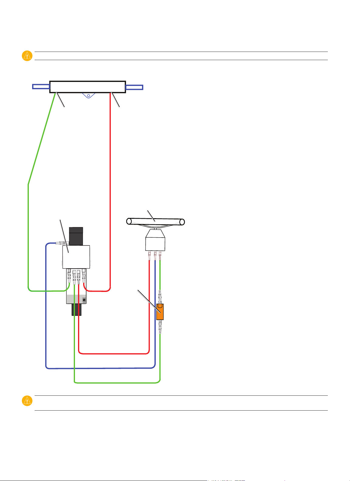
SeaStar Power Assist-Enabled Boats
Notes:
Starboard line
Power Assist module:
•
It may be necessary to remove the
◦
Power Assist module to gain access
to the ttings, the hoses, and the
bleed-tee tting.
S R P
Remove the bleed-tee tting from
◦
S R P
the Power Assist module and
relocate it to the return port on the
pump.
2.0 L/1.2 L pump (and motor):
•
Install the pump to the steering lines
◦
Helm
Helm
between the cylinder and the Power
Assist module.
Do not install the pump to the
◦
Bleed-tee tting
Bleed-tee tting
(relocate to the pump)
(relocate to the pump)
steering lines between the helm
and the Power Assist module.
An unbalanced cylinder requires
◦
an unbalanced valve on the pump
2.0 L/1.2 L pump
2.0 L/1.2 L pump
(and motor)
(and motor)
(See page 30)
Mount the pump horizontally if
◦
possible. Do not mount the pump
vertically with the pump end
(hydraulic connections) down.
Shadow Drive
•
Mount the Shadow Drive
◦
horizontally and as level as possible.
Install the Shadow Drive in either
◦
the port or the starboard hydraulic
steering line.
Always install a length of hose
◦
between the helm and the Shadow
Drive.
Do not install the Shadow Drive
◦
directly to the helm.
Install the Shadow Drive between the helm and the Power Assist module.
◦
◦
Do not install the Shadow Drive between the Power Assist module and the pump.
◦
Do not install the Shadow Drive between the Power Assist module and the cylinder.
Starboard line
Return line
Return line
Port line
Port line
Shadow drive
Shadow drive
Return line
Return line
Port tting
Port tting
H1 H2
H1 H2
C2C1
C2C1
Starboard tting
Starboard tting
Balanced cylinder
Balanced cylinder
Sea Star
Sea Star
Power Assist
Power Assist
module
module
CAUTION: Do not turn the system on until you bleed all the air from the Power Assist module, the helm, the Shadow Drive, the pump, and
all the hydraulic lines. See page 24.
7GHP 10 Marine Autopilot System Installation Instructions
Page 8
Hydraulic Considerations – 2.1 L Pump
Different boats have different hydraulic considerations you must examine before mounting the pump or cutting any hoses. Before
starting the hydraulic installation, verify the type of hydraulic steering in your boat, and where to install the appropriate type of pump.
CAUTION: If the hydraulic steering of your boat does not match the hydraulic layouts in this manual, contact Garmin Product Support.
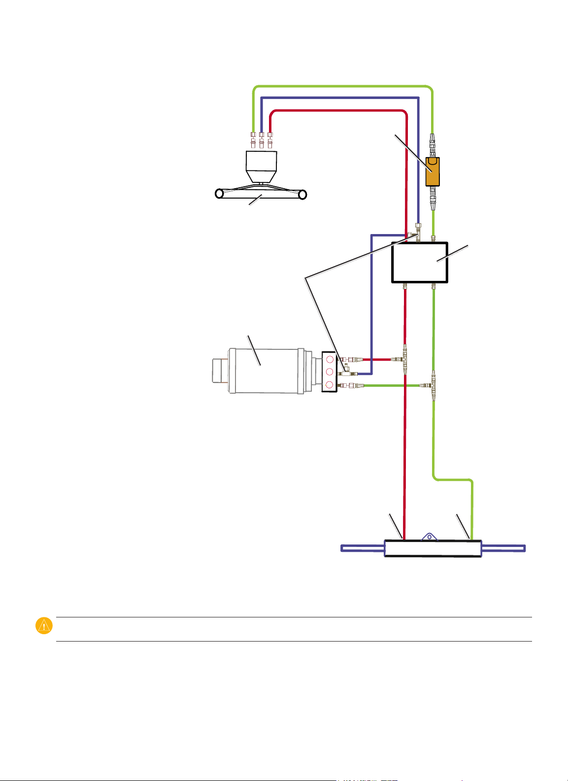
Single-Helm Boats
Balanced cylinder
Port ttingStarboard tting
Notes:
2.1 L pump (and motor):
•
Do not use the 2.1 L pump on a system with an
◦
unbalanced cylinder.
Mount the pump horizontally if possible. Do not
◦
mount the pump vertically with the pump end
(hydraulic connections) down.
2.1 L pump
(and motor)
Shadow drive
Helm
P R S
Shadow Drive
•
Mount the Shadow Drive horizontally and as
◦
level as possible.
Install the Shadow Drive in either the port or the
◦
starboard hydraulic line.
Always install a length of hose between the helm
◦
and the Shadow Drive.
Install the Shadow Drive between the pump and
◦
the helm.
Do not install the Shadow Drive directly to the
◦
helm.
Do not install the Shadow Drive between the
◦
pump and the cylinder.
Port line
Return line
Starboard line
CAUTION: Do not turn on the system until you bleed all the air from the Power Assist module, the helm, the Shadow Drive, the pump, and
all the hydraulic lines. See page 24.
8 GHP 10 Marine Autopilot System Installation Instructions
Page 9
Dual-Helm Boats
Balanced cylinder
Starboard tting
2.1 L pump
(and motor)
Port tting
Upper helm
Lower helm
P R S
P R S
Shadow drive
Port line
Return line
Starboard line
Notes:
2.1 L pump (and motor):
•
Do not use the 2.1 L pump on a system with an unbalanced cylinder.
◦
Mount the pump horizontally if possible. Do not mount the pump vertically with the pump end (hydraulic connections) down.
◦
Shadow Drive
•
Mount the Shadow Drive horizontally and as level as possible.
◦
Install the Shadow Drive in either the port or the starboard hydraulic line.
◦
Always install a length of hose between the helm and the Shadow Drive.
◦
Install the Shadow Drive between the pump and the helm.
◦
Do not install the Shadow Drive directly to the helm.
◦
Do not install the Shadow Drive between the pump and the cylinder.
◦
CAUTION: Do not turn on the system until you bleed all the air from the Power Assist module, the helm, the Shadow Drive, the pump, and
all the hydraulic lines. See page 24.
9GHP 10 Marine Autopilot System Installation Instructions
Page 10
SeaStar Power Assist-Enabled Boats
Notes:
Power Assist module:
•
It may be necessary to remove the Power Assist
◦
module to gain access to the ttings, the hoses,
and the bleed-tee tting
You may need to add a tee tting in the return
◦
line at the Power Assist module to connect the
pump.
2.1 L pump (and motor):
•
Install the pump to the steering lines between
◦
the cylinder and the Power Assist module.
Do not install the pump to the steering lines
◦
between the helm and the Power Assist
module.
Do not use the 2.1 L pump on a system with
◦
an unbalanced cylinder.
Mount the pump horizontally if possible. Do
◦
not mount the pump vertically with the pump
end (hydraulic connections) down.
Shadow Drive
•
Mount the Shadow Drive horizontally and as
◦
level as possible.
Install the Shadow Drive in either the port or
◦
the starboard hydraulic steering line.
Always install a length of hose between the
◦
helm and the Shadow Drive.
Install the Shadow Drive between the helm and
◦
the Power Assist module.
Do not install the Shadow Drive directly to
◦
the helm.
Do not install the Shadow Drive between the
◦
Power Assist module and the pump.
Do not install the Shadow Drive between the
◦
Power Assist module and the cylinder.
S R P
S R P
Helm
Helm
Return line
Return line
2.1 L pump (and motor)
2.1 L pump (and motor)
Starboard line
Starboard line
Return line
Return line
Port line
Port line
Sea Star
Sea Star
Power Assist
Power Assist
module
module
Port tting
Port tting
Shadow drive
Shadow drive
Starboard tting
Starboard tting
Balanced cylinder
Balanced cylinder
H1 H2
H1 H2
C2
C2
C1
C1
CAUTION: Do not turn the system on until you bleed all the air from the Power Assist module, the helm, the Shadow Drive, the pump, and
all the hydraulic lines. See page 24.
10 GHP 10 Marine Autopilot System Installation Instructions
Page 11

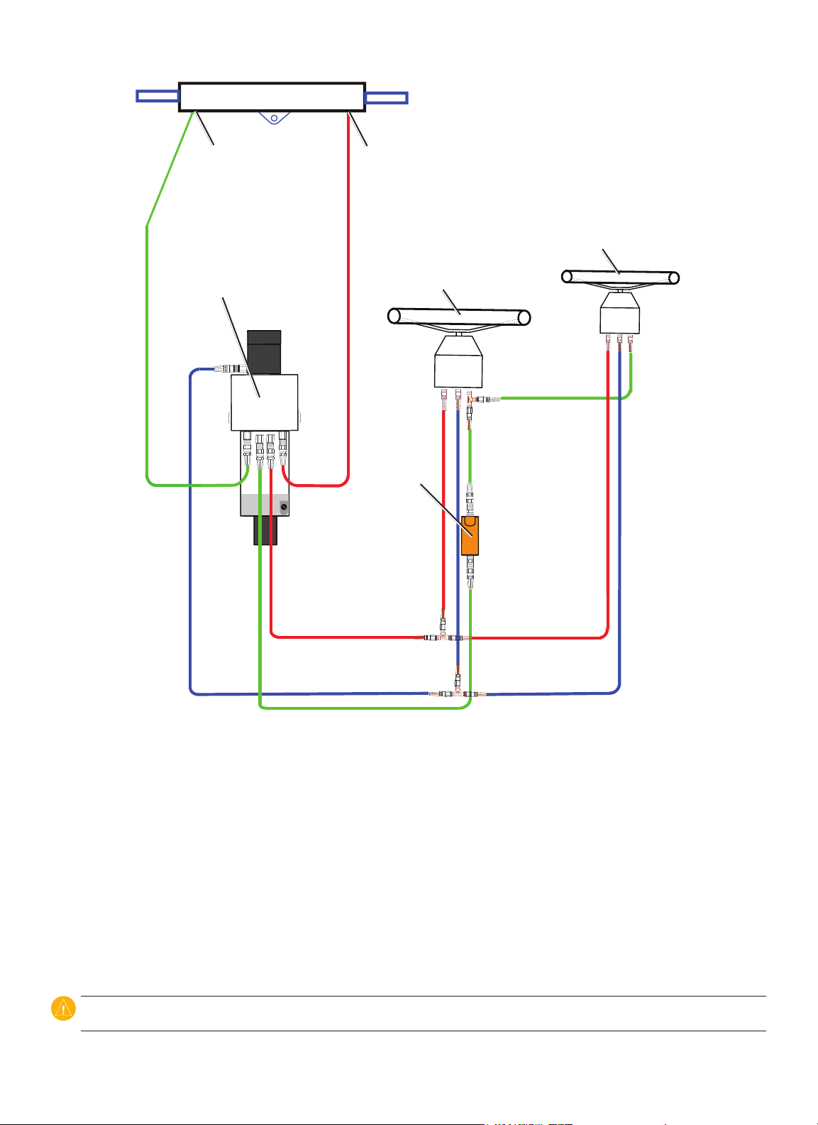
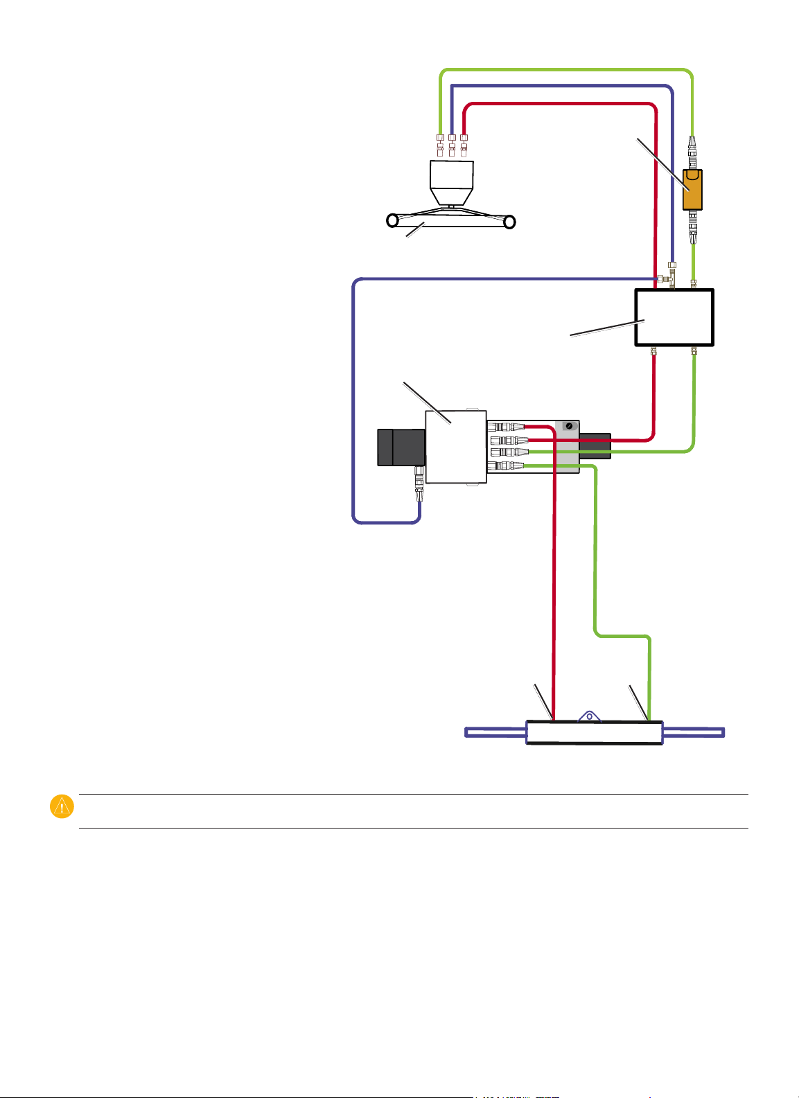
Electrical/Data Connection and Mounting Considerations
The GHP 10 components connect to each other and to power using the included cables. Ensure that the correct cables reach
each component, and that each component is in an acceptable location, before mounting any components. Read the following
considerations and consult the diagram on the next page before you begin installation.
The Pump and the ECU
The pump must be located within 19 in. (0.5 m) of the ECU, mounted horizontally if possible. If you cannot mount the pump
•
horizontally, do not mount the pump vertically with the pump head (connectors) down.
•
The cables from the pump to the ECU cannot be extended.
The ECU power cable connects to the boat battery.
•
The CCU and the ECU
Do not mount the CCU or the ECU in a location where they will be submerged or exposed to wash-down.
•
•
Mount the CCU in the forward half of the boat, no higher than 10 ft. (3.05 m) above the waterline.
You can mount the CCU below the waterline, as long as it is not in a location where it will be submerged or exposed to wash-
•
down.
Mount the CCU bracket on a vertical surface or under a horizontal surface, so that the connected wires hang straight down.
•
•
Do not mount the CCU near magnetic material, magnets (speakers and electric motors), or high-current wires.
CCU at least 24 in. (0.61 m) away from movable or changing magnetic disturbances such as anchors, anchor chain, wiper motors,
tool boxes, and the autopilot pump. Use a handheld compass to test for magnetic interference in the area.
The CCU/ECU interconnect cable connects the CCU to the ECU, and is 91/2 ft. (3 m) long. If you cannot mount the CCU within
•
91/2 ft. (3 m) of the ECU, extension cables are available in lengths of 16
The CCU/ECU interconnect cable connects the CCU to the Shadow Drive, the alarm buzzer, the tachometer of the boat, and the
•
yellow CCU signal wire of the GHC 10 using wires with bare ends. See page 17 for wiring instructions and diagrams.
1
/2 ft. (5 m) and 49 ft. (15 m). (See page 4).
Mount the
The CCU and the GHC 10
The CCU and the GHC 10 connect to a NMEA 2000 network. If you do not have a NMEA 2000 network on your boat, the
•
equipment necessary to build one is provided. For instructions on setting up the NMEA 2000 network, see page 21.
You can connect an optional NMEA 2000-compatible GPS device to the NMEA 2000 network to use waypoint and route data with
•
the GHP 10.
The GHC 10
Wire the GHC 10 to the battery of the boat and to the yellow CCU signal wire of the CCU/ECU interconnect cable.
•
If you do not have an optional NMEA 2000-compatible GPS device, you can wire an optional NMEA 0183-compatible GPS
•
device to the power/data cable of the GHC 10 instead (see page 23).
The Shadow Drive
Install the Shadow Drive closer to the helm than to the pump.
•
Mount the Shadow Drive horizontally, as level as possible.
•
Mount the Shadow Drive at least 12 in. (0.3 m) away from magnetic material such as speakers and electric motors,
•
including the autopilot pump.
11GHP 10 Marine Autopilot System Installation Instructions
Page 12

ENCODER
CCU
POWER
}
PUMP
Ignition or
in-line switch
Yellow CCU signal wire
(see page 20)
8-32 Vdc
1 A fuse
Black (-)
GHC 10
Red (+)
9-16 Vdc
3 A fuse
Pump
(2.1 L pictured)
Red (+)
Black (-)
Drain (-)
NMEA 2000 power cable
Red (+)
12 Vdc
40 A fuse
NMEA 2000 network (see page 21)
ECU
Black (-)
CCU/ECU Interconnect cable
GHP 10 General Wiring Outline
CCU
For tachometer wiring,
see page 18
Boat tachometer
Orange - unconnected
White (+)
Red (+)
Blue (-)
For CCU bare-wire connections, see page 17.
Brown (+)
Yellow CCU signal wire (see page 20)
Black (-)
Alarm buzzer
Red (+)
Black (-)Black (-)
Shadow Drive
Notes:
This diagram is for planning purposes. Specic wiring diagrams are included in the detailed installation instructions for each
•
component. Hydraulic connections are not shown in this diagram.
Connect an optional NMEA 0183-compatible GPS device to the power/data cable on the GHC 10. See page 23 for more
•
information.
Connect an optional NMEA 2000-compatible GPS device to the NMEA 2000 network. See page 23 for more information.
•
12 GHP 10 Marine Autopilot System Installation Instructions
Page 13

Installation Procedures
After you have completely planned the GHP 10 installation on your boat, and have satised all the hydraulic, mounting, and wiring
considerations for your particular installation, you can begin mounting and connecting the components.
Installing the Pump (and Motor)
Install the pump by mounting it on your boat, connecting it to the hydraulic steering lines of your boat, and connecting it to the ECU.
If your boat uses an unbalanced-cylinder steering system, be sure you have a 2.0 L or 1.2 L pump with the unbalanced kit installed. If
your 2.0 L or 1.2 L pump does not have an unbalanced kit installed, follow the directions on page 30 to install an unbalanced kit for
use with an unbalanced-cylinder steering system. Do not use a 2.1 L pump with an unbalanced-cylinder steering system.
Mounting the Pump
Mount the pump horizontally on a solid surface. Mounting the pump horizontally on the oor is preferable, but you can also mount the
pump horizontally on a wall. If horizontal mounting is not possible, do not install the pump vertically with the pump head (containing
the hose ttings) down. Mount the pump within 19 in. (.5 m) of the ECU. Mount the pump in a location to which you can extend
the hydraulic steering lines of the boat.
To mount the pump:
1. Determine the best location for the pump on your boat, satisfying the hydraulic and wiring considerations.
2. Determine the correct type of screws for the mounting surface. Mounting screws are included with the pump, but you may need to
provide different screws if the supplied screws are not suitable for the mounting surface.
3. Use the correct mounting template for your pump. The templates are provided on page 33. Tape the template to the mounting
location and use a center punch and hammer to mark the pilot-hole locations.
4. Drill pilot holes at the four mounting locations.
5. Use screws to mount the pump.
NOTE: To reduce noise while the autopilot is running, install a vibration-isolation mounting pad between the pump and the mounting
surface.
6. Use a spray-on corrosion blocker on the pump after it is mounted and all hydraulic and electrical connections are made.
Connecting the 2.0 L or the 1.2 L Pump to the Hydraulic Lines
Before disconnecting any hydraulic lines on your boat, consult the manufacturer of your boat or steering system. You must know how
to properly prepare the hoses for removal, and you must know how to properly bleed the hydraulic system of air when you complete
the connections. When adding hydraulic hose to the steering system, only use hose with machine-crimped or eld-replaceable
ttings that have a minimum rating of 1000 lb/in
The 2.0 L and the 1.2 L pump manifolds have two sets of hose-connector ttings, both upper and lower, to allow for different
hose congurations. You can use the upper ttings, the lower ttings, or a combination of the two. Do not use Teon tape on any
hydraulic tting. Use an appropriate thread sealant such as Loctite Pro Lock Tight multipurpose anaerobic gel, part number 51604, or
equivalent, on all pipe threads in the hydraulic system.
Pump/motor body
2
.
Upper ttings
Lower ttings
Pump manifold
13GHP 10 Marine Autopilot System Installation Instructions
Page 14

To connect the pump to the hydraulic lines:
1. Consult the hydraulic layout diagrams starting on page 5 to nd the correct place to connect the pump to your hydraulic system.
2. Prepare to disconnect the hydraulic lines in your boat as specied by the manufacturer of your boat or steering system.
3. Disconnect the hydraulic lines from the steering system where appropriate.
4. Add additional hose where necessary, and add the included t-connectors in the hydraulic lines.
5. Add hydraulic hose from the t-connectors to the pump, using the included ttings to attach the hose to the pump.
6. Add hydraulic hose from the return connector at the back of the helm to the pump, using the included ttings.
7. Connect the hoses to the upper ttings, the lower ttings, or a combination of both ttings on the pump. Do not connect more than
three hoses to the pump (port, starboard, and return).
8. Insert, tighten, and seal the included plugs in the three unused pump ttings.
9. You will eventually need to bleed the hydraulic system, but not until the Shadow Drive is installed. See page 24 for more
information.
NOTE: The pump may vibrate the hydraulic lines and cause noise when the autopilot is running. To eliminate the noise, tie the hydraulic
lines to a solid surface.
Operating the Shutoff Valve
The 2.0 L and the 1.2 L pumps feature a shutoff valve for troubleshooting and repairing the system. To engage the shutoff valve and
isolate the pump from the hydraulic system, fully tighten the three brass screws near the lower hydraulic connectors. To disengage the
shutoff valve, loosen the three brass screws until they stop.
Socket-headed cap screws
Brass shutoff
screws
Socket-headed cap screws
CAUTION: Do not force the three brass screws past the stopping point when disengaging the shutoff valve. Forcing the screws past the
stopping point may permanently damage the manifold.
When the shutoff valve is engaged, the boat will steer normally, and the pump will not control the steering system. When the shutoff
valve is engaged, you can remove the pump from the system for repair without disconnecting any hydraulic lines.
To remove the pump from the shutoff-valve manifold:
1. Tighten the three brass screws near the lower hydraulic connectors.
2. Remove the four socket-head cap screws that connect the manifold to the pump.
3. The manifold is no longer connected to the pump, and the pump can be disconnected from the ECU and removed from its
mounting location. The hydraulic steering system will operate normally.
To reconnect the pump to the shutoff-valve manifold:
1. Remount the pump and reconnect the pump to the ECU.
2. Connect the manifold to the pump using the four socket-head cap screws.
3. Loosen the three brass screws near the lower hydraulic connectors until they stop. Do not loosen the screws past the stopping
point.
Connecting the Pump to the ECU
Do not connect the pump to the ECU until you have mounted the ECU to the boat following the procedures on page 16.
14 GHP 10 Marine Autopilot System Installation Instructions
Page 15

Connecting the 2.1 L Pump to the Hydraulic Lines
The 2.1 L pump must be isolated from the electrical ground of the boat. Use insulating washers under the pump if it is installed on an
electrically-grounded (metal) surface. Install the washers between the pump bracket and the grounded surface
Before disconnecting any hydraulic lines on your boat, consult the manufacturer of your boat or steering system. You must know how
to properly prepare the hoses for removal, and you must know how to properly bleed the hydraulic system of air when you complete
the connections. When adding hydraulic hose to the steering system, only use hose with machine-crimped or eld-replaceable
ttings that have a minimum rating of 1000 lb/in
Install the 2.1 L pump inline with the hydraulic steering lines of the boat. The 2.1 L pump does not branch off of the hydraulic steering
lines like the 2.0 L or the 1.2 L pumps. The 2.1 L pump manifold has ve hose-connector ttings, three to the helm (port, starboard,
and return), and two to the cylinder (port and starboard). Do not use Teon tape on any hydraulic tting. Use an appropriate thread
sealant such as Loctite Pro Lock Tight multipurpose anaerobic gel, part number 51604, or equivalent, on all pipe threads in the
hydraulic system.
2
.
Cylinder starboard
connector
Helm starboard
connector
Pump/motor
body
To connect the pump to the hydraulic lines:
1. Consult the hydraulic layout diagrams starting on page 8 to determine the correct place to connect the pump to your hydraulic
system.
2. Prepare to disconnect the hydraulic lines in your boat as specied by the manufacturer of your boat or steering system.
3. Disconnect the hydraulic lines from the steering system where appropriate.
4. Remove the plugs from the ve connectors on the pump.
5. Add hydraulic hose as necessary, and route the hose to the pump.
6. Use the included ttings to attach the hoses to the pump. Use the above diagram to identify the connectors on the pump.
7. Add hydraulic hose from the return connector at the back of the helm to the pump.
8. Connect the hose to the helm and to the return-line connector on the pump using the included ttings.
9. You will eventually need to bleed the hydraulic system, but not until the Shadow Drive is installed. See page 24 for more
information.
Cylinder port
connector
Helm port
connector
Helm return-line
connector
NOTE: The pump may vibrate the hydraulic lines and cause noise when the autopilot is running. To eliminate the noise, tie the hydraulic
lines to a solid surface.
Connecting the Pump to the ECU
Do not connect the pump to the ECU until you have mounted the ECU to the boat following the procedures on page 16.
15GHP 10 Marine Autopilot System Installation Instructions
Page 16

Installing the Electronic Control Unit (ECU)
To install the ECU, mount it to your boat, connect it to the pump and to the CCU, and wire it to the boat battery.
Mounting the ECU
Mount the ECU horizontally on a at surface within 19 in. (.5 m) of the pump. The cables from the pump cannot be extended.
Mount the ECU in a location where you can run wire to the boat battery, but do not connect it to the battery at this time. The power
wire can be extended, if necessary. Use the table on page 24 to determine the correct type of wire for extending the battery cable.
To mount the ECU:
1. Determine the best location for the ECU on your boat, satisfying the wiring considerations.
2. Determine the correct type of screws for the mounting surface. Mounting screws are included with the ECU, but you may need to
provide different screws if the supplied screws are not suitable for the mounting surface.
3. Use the mounting template provided on page 31. Tape the template to the mounting location and use a center punch and hammer
to mark the pilot-hole locations.
4. Drill pilot holes at the four mounting locations.
5. Use screws to mount the ECU.
Wiring the ECU
Connect the two wires from the pump to the connectors marked PUMP and ENCODER on the ECU. The connectors are keyed to the
appropriate ttings on the wires. Do not connect the ECU to power until all the connections of the entire GHP 10 system have
been completed (page 24). Wait to connect the CCU/ECU interconnect cable until you have mounted the CCU by following the
procedures in the next section.
Installing the Course Computer Unit (CCU)
Install the CCU by mounting it to your boat, connecting it to the ECU and to a NMEA 2000 network, and wiring it to the Shadow
Drive, to the tachometer of your boat, to the alarm buzzer, and to the yellow CCU signal wire on the GHC 10.
Mounting the CCU
Mount the CCU on the boat by using the included bracket. The CCU bracket has two portions, the mounting portion and the securing
portion. Install the mounting portion on the mounting surface, and secure the CCU in the bracket with the securing portion.
When mounting the CCU:
Mount the CCU in the forward half of the boat, no higher than 10 ft. (3.05 m) above the waterline.
•
You can mount the CCU below the waterline, as long as it is not in a location where it will be submerged or exposed to wash-down.
•
Mount the CCU bracket on a vertical surface or under a horizontal surface, so that the connected wires hang straight down.
•
Do not mount the CCU near magnetic material, magnets (speakers and electric motors), or high-current wires.
•
Mount the CCU at least 24 in. (0.6 m) away from movable or changing magnetic disturbances such as anchors, anchor chain,
•
wiper motors, tool boxes, and the autopilot pump.
Use a handheld compass to verify the absence of magnetic interference. If the handheld compass does not point north when you
•
hold it in the location you want to mount the CCU, then there is magnetic interference. Choose another location and test again.
If possible, mount the CCU within 9
•
extensions are available in lengths of 16
To mount the CCU bracket
1. Determine the best location for the CCU on your boat. Use a handheld compass to be
sure that the location is free of magnetic interference.
2. Determine the correct type of screws for the mounting surface. Mounting screws are
included with the CCU, but you may need to provide different screws if the supplied
screws are not suitable for the mounting surface.
3. Use the mounting template provided on page 31. Be sure to install the mounting
portion of the bracket with an opening at the bottom. Tape the template to the mounting
location and use a center punch and hammer to mark the pilot-hole locations.
4. Drill pilot holes at the three mounting locations.
5. Use screws to secure the mounting portion of the CCU bracket.
1
/2 ft. (3 m) of the ECU. If you cannot mount the CCU within 9
1
/2 ft. (5 m) and 49 ft. (15 m). (See page 4.)
Thumbscrew
Thumbscrew
Mounting
Mounting
screws (×3)
screws (×3)
1
/2 ft. (3 m) of the ECU,
Opening for cables
Opening for cables
16 GHP 10 Marine Autopilot System Installation Instructions
Page 17

To secure the CCU in the CCU bracket:
1. Connect the CCU/ECU interconnect cable and the NMEA 2000 drop cable to the CCU.
2. Place the CCU in the mounting portion of the CCU bracket with the wires hanging straight down,
toward the water.
3. Place the securing portion of the bracket over the ball and snap it into the mounting portion of the
bracket, starting with the two arms that do not have the thumbscrew.
4. Make sure the cables hang straight down, toward the water, and connect the arm with the
thumbscrew. The cables must hang straight down for the CCU to accurately read your
heading.
5. Hand-tighten the thumbscrew until the CCU is held rmly in the bracket. Do not overtighten the
thumbscrew.
Thumbscrew
Thumbscrew
Wiring the CCU
Route the connector-terminated end of the CCU/ECU interconnect cable to the ECU and make the
Cables
connection. Do not connect the bare-wire portion of the cable CCU/ECU interconnect cable at this
Cables
time. Before you connect the bare-wire portion, install the Shadow Drive and the alarm buzzer (page
18), and mount the GHC 10 (page 19).
Installing the Shadow Drive
Install the Shadow Drive by connecting it to the hydraulic steering line of your boat and wiring it to the CCU/ECU interconnect cable.
Connecting the Shadow Drive to the Hydraulics
Choose a location at which to connect the Shadow Drive to the hydraulic steering of your boat by consulting the hydraulic-layout
diagrams starting on page 5. Use the included connectors to install the Shadow Drive in the hydraulic line.
When connecting the Shadow Drive to the hydraulic system:
Install the Shadow Drive lower than the helm, but higher than the pump. Mount the Shadow drive horizontally, and as level as
•
possible, using cable ties to rmly secure it in place.
Avoid making loops in the hydraulic lines. Install the Shadow Drive closer to the helm than to the pump.
•
Do not mount the Shadow Drive within 12 in. (0.3 m) of any magnetic interference such as speakers and electric motors.
•
Do not install the Shadow Drive directly to the ttings at the back of the helm. Install a length of hose between the tting at the
•
helm and the Shadow Drive.
Do not install the Shadow Drive directly to a hydraulic t-connector in the hydraulic line. Install a length of hose between a
•
t-connector and the Shadow Drive.
In a single-helm installation, do not install a t-connector between the helm and the Shadow Drive.
•
In a dual-helm installation, install the Shadow Drive between the pump and the lower helm, closer to the helm than to
•
the pump.
Install the Shadow Drive in either the starboard steering line or the port steering line. Do not install the Shadow Drive in the
•
return line.
Do not use Teon tape on any hydraulic tting. Use an appropriate thread sealant such as Loctite Pro Lock Tight multipurpose
•
anaerobic gel, part number 51604, or equivalent, on all pipe threads in the hydraulic system.
Wiring the Shadow Drive
Wire the Shadow Drive to the CCU/ECU interconnect cable.
To wire the Shadow Drive:
1. Route the bare-wire end of the CCU/ECU interconnect cable to the Shadow Drive. If the cable is not long enough, extend the
appropriate wires with 28 AWG wire.
2. Use the Shadow Drive Wiring Table to make the appropriate connections.
Shadow Drive Wire Color CCU/ECU Interconnect Cable Wire Color
Red (+) Brown (+)
Black (-) Black (-)
Shadow Drive Wiring Table
3. Solder and cover all bare-wire connections.
17GHP 10 Marine Autopilot System Installation Instructions
Page 18

Wiring the GHP 10 to the Tachometer
The tachometer connection is an important part of the GHP 10 system, and must be wired correctly for the autopilot to function. If
your engine supports NMEA 2000 engine data, and is connected to the same NMEA 2000 network as the GHC 10 and the CCU, then
no other tachometry wiring is necessary. For more information on the NMEA 2000 network, see page 21. If your engine does not
support NMEA 2000 engine data, then wire the GHP 10 autopilot system to the tachometer of your boat using the bare-wire portion of
the CCU/ECU interconnect cable. In most cases, this connection can be made behind the dashboard at the tachometer display. Refer
to the owner’s manual or shop manual for your engine to identify the color codes and location of the tachometer wiring on
your boat.
To wire the GHP 10 to the tachometer of your boat:
1. Identify the location and wire assignments of the tachometer (or tachometers) on your boat.
2. Route the bare-wire end of the CCU/ECU interconnect cable to the tachometer (or tachometers). If the cable is not long enough,
extend the wires with twisted pair, 22 AWG wire.
3. Use the Tachometer Wiring Table to determine the appropriate wires on the CCU/ECU interconnect cable. Connect the tachometer
wire or wires from the CCU/ECU interconnect cable to the tachometer sensor wire or wires from the engine ((or engines)). Connect
the ground wires to a clean ground.
Engine Conguration Tachometer Ground
Single engine Green and violet (twist together) White and grey (twist together)
Dual engines Port engine = violet Grey
Starboard engine = green White
Tachometer Wiring Table
NOTE: For three or more outboard engines, connect to the outermost port and starboard engines, according to the table.
4. Solder and cover all bare-wire connections.
Installing the Alarm Buzzer
The alarm buzzer audibly alerts you to important GHP 10 events. It must be installed near the helm station.
Mounting the Alarm Buzzer
Mount the alarm buzzer near the helm station. You can mount the alarm buzzer under the dashboard if you prefer. Secure the alarm
buzzer with cable ties or other appropriate mounting hardware (not included).
Wiring the Alarm Buzzer
Wire the alarm buzzer to the CCU/ECU interconnect cable.
To wire the alarm buzzer:
1. Route the alarm-buzzer cable to the bare-wire end of the CCU/ECU interconnect cable. If the cable is not long enough, extend the
appropriate wires with 28 AWG wire.
2. Use the Alarm Buzzer Wiring Table to make the appropriate connections.
Alarm Buzzer Wire Color CCU/ECU Interconnect Cable Wire Color
White (+) Red (+)
Black (-) Blue (-)
Alarm Buzzer Wiring Table
3. Solder and cover all bare-wire connections.
18 GHP 10 Marine Autopilot System Installation Instructions
Page 19

Installing the GHC 10
Install the GHC 10 by ush-mounting it in the dashboard near the helm, connecting it to power and to the yellow CCU signal wire
from the CCU/ECU interconnect cable, and connecting it to a NMEA 2000 network. Optionally, you can connect the GHC 10 to a
NEMA 2000 or NMEA 0183-compatible GPS device to use waypoint and route data.
Mounting the GHC 10
Flush mount the GHC 10 in the dashboard near the helm.
When you select an installation location for the GHC 10, choose a location with the following characteristics:
Provides optimal viewing as you operate your vessel.
•
Allows easy access to the keypad on the GHC 10.
•
Is strong enough to support the weight of the GHC 10 and protect it from excessive vibration or shock.
•
Allows room for the routing and connection of the cables for power and data. There should be at least a 3-inch (8 cm) clearance
•
behind the case.
Is at least 91/2 in. (0.24 m) from a magnetic compass, to avoid interference.
•
Is in an area that is not exposed to extreme temperature conditions.
•
NOTE: The temperature range for the GHC 10 is from 5°F to 158°F (from -15°C to 70°C). Extended exposure to temperatures outside of
this range (in storage or operating conditions) may cause failure of the LCD screen or other components. This type of failure and related
consequences are not covered by the manufacturer’s limited warranty.
To ush mount the GHC 10:
1. The ush-mount template is included in the product box. Trim the template and ensure it will t in the location at which you want to
ush mount the GHC 10.
2. The ush-mount template has adhesive on the back. Remove the protective liner and
apply the template to the location where you want to ush mount the GHC 10.
3. If you will be cutting the hole with a jigsaw, and not a 317/
3
/8 in. (10 mm) drill bit to drill a pilot hole as indicated on the template to begin cutting the
mounting surface.
4. Using the jigsaw or the 317/
32
in. (90 mm) hole saw, cut the mounting surface along
the inside of the dashed line indicated on the ush-mount template. Use a le and
sandpaper to rene the size of the hole.
5. Place the GHC 10 into the cutout to conrm that the four mounting holes are correct
after rening the hole. If not, mark the correct locations of the four mounting holes.
Remove the GHC 10 from the cutout.
6. Using the center punch, indent the center of each of the four pilot-hole locations.
7. Drill the four
1
/8 in. (3.2 mm) pilot holes.
32
in. (90 mm) hole saw, use a
NOTE: If you are mounting the GHC 10 in berglass, it is recommended to use a countersink bit to drill a clearance counterbore through
only the top gel-coat layer. This will help to avoid any cracking in the gel-coat layer when the screws are tightened.
8. Remove the remainder of the template.
9. Place the GHC 10 into the cutout.
10. Securely tighten the four mounting screws through the GHC 10 into the drilled mounting holes.
NOTE: Stainless-steel screws may bind when screwed into berglass and overtightened. Garmin recommends applying an anti-galling,
stainless anti-seize lubricant to the screws before installing them.
11. Snap the mounting covers into place to install them.
19GHP 10 Marine Autopilot System Installation Instructions
Page 20

Wiring the GHC 10 to Power and to the CCU/ECU Interconnect Cable
With the GHC 10 power/data cable, wire the GHC 10 to power and to the yellow CCU signal wire on the CCU/ECU interconnect
cable. Optionally, you can wire the GHC 10 power/data cable to a NMEA 0183-compatible GPS device to use waypoint and route
information with the GHP 10, although a NMEA 2000 GPS device is preferred.
To wire the GHC 10 to power:
1. Route the GHC 10 power/data cable to the boat battery.
2. Use a voltmeter to determine the polarity of the voltage source.
3. Connect the red (+ or positive) wire to the positive voltage terminal. (If you use the fuse
block on the boat, route the positive connection through the fuse.)
4. Connect the black (- or ground) wire to the negative voltage terminal.
5. Install or check the AGC/3AG – 1 A fuse (on the fuse block or in the in-line holder).
6. Do not connect the power/data cable to the GHC 10 until all the connections of the
entire GHP 10 system have been completed (page 24).
Notes:
The replacement fuse is an AGC/3AG – 1 A fuse.
•
If it is necessary to extend the power wires, use 18 AWG wire.
•
If your boat has an electrical system, you might be able to wire the GHC 10 directly to an unused holder on your current fuse
•
block. If you are using the fuse block, remove the in-line fuse holder supplied with the GHC 10.
CAUTION: The GHC 10 maximum input voltage is 32 Vdc. Do not exceed this voltage, because this can damage the GHC 10 and void the
warranty.
Power/data NMEA 2000Power/data NMEA 2000
NOTE: During a typical installation, use only the red, black, and yellow wires. The other wires are used for NMEA 0183 connections, and do
not have to be connected for normal operation of the GHC 10. For information on connecting to a NMEA 0183-compatible GPS device, see
page 23.
To wire the yellow CCU signal wire from the GHC 10 power/data cable to the CCU/ECU interconnect cable:
1. Route the GHC 10 power/data cable to the bare end of the color-coded wires from the CCU/ECU interconnect cable. If the cable is
not long enough, extend the yellow CCU signal wire with 22 AWG wire.
2. Connect the yellow CCU signal wire from the GHC 10 power/data cable to the yellow wire on the CCU/ECU interconnect cable.
If you install multiple GHC 10 units and want to turn the GHP 10 autopilot system on with any of the installed GHC 10 units,
connect all of the yellow CCU signal wires from the GHC 10 units to the yellow wire on the CCU/ECU interconnect cable.
3. Solder and cover all bare-wire connections.
NOTE: The yellow CCU signal wire must be connected from the GHC 10 power/data cable to the CCU/ECU interconnect cable, or the GHP
10 autopilot system will not power on with the GHC 10.
20 GHP 10 Marine Autopilot System Installation Instructions
Page 21

Connecting the GHC 10 to a NMEA 2000 Network
Connect the GHC 10 to the CCU through your existing NMEA 2000 network. If you do not have an existing NMEA 2000 network
on your boat, all the parts needed to build one are supplied in the GHP 10 package. Optionally, you can connect a NMEA 2000compatible GPS device to your NMEA 2000 network to use waypoint and route information with the GHP 10. For more information
on NMEA 2000, visit www.garmin.com.
To connect the GHC 10 to your existing NMEA 2000 network:
1. Determine where you would like to connect the GHC 10 to your existing NMEA 2000 network.
2. Disconnect one side of a NMEA 2000 T-connector from the network at an appropriate location.
If you need to extend the NMEA 2000 network backbone, connect an appropriate NMEA 2000 backbone extension cable (not
included) to the side of the T-connector you disconnected.
3. Add the included T-connector for the GHC 10 in the NMEA 2000 network by connecting it to the side of the T-connector you
disconnected.
4. Route the included drop cable to the bottom of the T-connector you just added to your NMEA 2000 network.
If the included drop cable is not long enough, you can use a drop cable up to 20 ft. (6 m) long (not included).
5. Connect the drop cable to the T-connector and the GHC 10.
6. Do not power the NMEA 2000 network on until all of the GHP 10 components are installed correctly. (See page 24.)
CAUTION: If you have an existing NMEA 2000 network on your boat, it should already be connected to power. Do not connect the
included NMEA 2000 power cable to an existing NMEA 2000 network, because only one power source should be connected to a NMEA
2000 network.
CCU
GHC 10
Optional
NMEA 2000
GPS device
(not included)
Additional
Drop cable
(included)
T-connector
(included)
Connecting the GHC 10 (and CCU) to an Existing
drop cable
and
T-connector
(not included)
Existing NMEA 2000 network
NMEA 2000 Network
Drop cable
(included)
T-connector
(included)
To connect the CCU to your existing NMEA 2000 network:
1. Determine where you would like to connect the CCU to your existing NMEA 2000 network.
2. Disconnect one side of a NMEA 2000 T-connector from the network at an appropriate location.
If you need to extend the NMEA 2000 network backbone, connect an appropriate NMEA 2000 backbone extension cable (not
included) to the side of the T-connector you disconnected.
21GHP 10 Marine Autopilot System Installation Instructions
Page 22

3. Add the included T-connector for the CCU in the NMEA 2000 network by connecting it to the side of the T-connector you
+
-
disconnected.
4. Route the included drop cable to the bottom of the T-connector you just added to your NMEA 2000 network.
If the included drop cable is not long enough, you can use a drop cable up to 20 ft. (6 m) long (not included).
5. Connect the drop cable to the T-connector and the CCU.
6. Do not power the NMEA 2000 network on until all of the GHP 10 components are installed correctly. (See page 24.)
CAUTION: If you have an existing NMEA 2000 network on your boat, it should already be connected to power. Do not connect the
included NMEA 2000 power cable to an existing NMEA 2000 network, because only one power source should be connected to a NMEA
2000 network.
Notes:
The GHC 10 is not powered by the NMEA 2000 network. It must be separately connected to the power source.
•
The GHC 10 must also connect to the CCU with the yellow CCU signal wire in the GHC 10 power/data cable.
•
To add additional sensors to your NMEA 2000 network, follow the instructions included with the sensor.
•
To create a basic NMEA 2000 Network for the GHC 10 and the CCU:
1. Connect the three T-connectors together by their sides.
2. The included NMEA 2000 power cable must be connected to a 12 Vdc power source through a switch. Connect to the ignition
switch of the boat if possible, or through an appropriate additional switch (not included).
3. Connect the NMEA 2000 power cable to one of the T-connectors.
4. Connect one of the included NMEA 2000 drop cables to one of the T-connectors and to the GHC 10.
5. Connect the other included NMEA 2000 drop cable to the remaining T-connector and to the CCU.
6. Connect the appropriate terminators to each end of the combined T-connectors.
7. Do not power the NMEA 2000 network on until all of the GHP 10 components are installed correctly. (See page 24.)
CAUTION: You must connect the included NMEA 2000 power cable to the boat ignition switch, or through another in-line switch. The
GHC 10 will drain your battery if it is connected directly.
GHC 10
Ignition or
in-line switch
Fuse
12 Vdc battery
Drop cables
Power cable
T-connectors
Female
terminator
CCU
Male
terminator
Creating a Basic NMEA 2000 Network for the GHC 10 and the CCU
Notes:
To add additional sensors to your NMEA 2000 network, follow the instructions included with the sensor.
•
The GHC 10 is not powered by the NMEA 2000 network. It must be separately connected to the power source.
•
The GHC 10 must also connect to the CCU with the yellow CCU signal wire in the GHC 10 power/data cable.
•
22 GHP 10 Marine Autopilot System Installation Instructions
Page 23

Connecting an Optional GPS Device to the GHP 10 Autopilot System
>
>
>
>
+
-
>
>
>
>
Connect an optional GPS device to the NMEA 2000 network to use waypoint and route information with the GHP 10. Alternatively,
you can connect a NMEA 0183-compatible GPS device to the GHC 10 to use waypoint and route information with the GHP 10.
To connect an optional NMEA 2000-compatible GPS device to your GHP 10:
1. Add an additional T-connector (not included) for the optional GPS device you want to add to the NMEA 2000 network.
2. Connect the GPS device to the T-connector by following the instructions provided with the GPS device.
To connect an optional NMEA 0183-compatible GPS device to your GHP 10:
1. Determine the NMEA 0183 wiring assignments of your NMEA 0183-compatible GPS device.
2. Use the GHC 10 power/data cable wiring diagrams to correctly wire your NMEA 0183-compatible GPS device.
3. Use 22 AWG twisted-pair wire for extended runs of wire.
4. Solder and cover all bare-wire connections.
Color Function
GHC 10
Device
Fuse
1 A
Red
Black
Yellow
Power
Ground
CCU Signal
Blue
White
Brown
Green
GHC 10 Power/Data Cable
Spare
Spare
Rx/A(+)
Rx/B(-)
Example:
Battery
12 Vdc
WIRE
FUNCTION
RED
POWER GND
NMEA GND
Tx/A (+)
Tx/B (-)
NMEA 0183 Compatible
Device
GHC 10
Device
WIRE
COLOR
Fuse
RED
BLACK
1 A
BROWN
GREEN
Wiring the GHC 10 to a NMEA 0183 Device
Notes:
Consult the installation instructions for your NMEA 0183-compatible device to identify the Transfer (Tx) A(+) and B(-) wires.
•
If your NMEA 0183-compatible device has only one transmitting wire (Tx), connect it to the brown wire (Rx/A) from the GHC 10,
•
and connect the green wire (Rx/B) to ground.
The blue (Tx/A) and white (Tx/B) wires are not used when wiring the GHC 10 to a GPS device.
•
The yellow (CCU signal) wire must be wired to the yellow wire of the CCU/ECU interconnect cable.
•
23GHP 10 Marine Autopilot System Installation Instructions
Page 24

Making the Final Power Connections
After all the components are mounted, connected to the hydraulics of your boat, and wired correctly, connect the ECU to the boat
battery and connect the power/data cable to the GHC 10. Use the checklist provided in the back of this manual to ensure that the
preceding installation procedures are complete. Connect the ECU power cable directly to the boat battery if possible. Though it is not
recommended, if you connect the power cable to a terminal block or other source, connect it through a 40 A supply.
CAUTION: Do not remove the in-line fuse holder from the battery cable when connecting to the battery. If you remove the in-line fuse
holder, you will void the GHP 10 warranty, and may damage the GHP 10 autopilot system.
To connect the ECU to the battery:
1. Route the connector-terminated end of the ECU power cable to the ECU, and route the bare-wire end of the ECU power cable to
the boat battery. If the wire is not long enough, use the Wire Gauge Table to determine the correct wire gauge for an extended run.
Extended Length 10 ft. (3 m) 15 ft. (4.5 m) 20 ft. (6 m) 25 ft. (7.5 m)
Recommended Wire Gauge 12 10 10 8
Wire Gauge Table
2. Connect the black wire (-) to the negative (-) side of the battery rst.
3. Connect the red wire (+) to the positive (+) side of the battery next.
4. Connect the ECU power cable to the ECU last.
To connect the power/data cable to the GHC 10:
Align the notches on the cable plug and on the back of the GHC 10. Insert the cable into the connector, and turn the locking ring
clockwise until it stops.
NOTE: After the ECU and the GHC 10 are connected to power, the GHP 10 autopilot system and the NMEA 2000 network can be powered
on.
Bleeding the Hydraulic Steering System
Air must be purged completely from all the hydraulic lines, the helms, the cylinders, the pump, and the Shadow Drive for the system
to function. If the hydraulic system is not bled, then the GHP 10 autopilot system will not work correctly. Follow the instructions
provided by the manufacturer of your steering system to properly bleed the hydraulic system on your boat. Treat the pump as
the lowest helm when bleeding the system.
Notes:
Disable the Shadow Drive from the GHC 10 to make the bleeding process easier. On the GHC 10, select Menu > Setup >
•
Autopilot Conguration > Hydraulic Setup > Shadow Drive Enable. Change the Shadow Drive Enable setting to Disable.
Remember to enable the Shadow Drive after the bleeding process is complete.
•
To completely bleed the hydraulic system, it may be necessary to drive the autopilot pump in both directions to remove any air
•
trapped within the pump. You can do this during the Verify Steering Direction portion of the Dockside Wizard (see page 25).
Drive the rudder to each stop in each direction, and then perform any additional bleeding that may be necessary.
IMPORTANT: Check for leaks at every hydraulic tting, both after the bleeding process is complete and after the sea trial is complete.
24 GHP 10 Marine Autopilot System Installation Instructions
Page 25

Conguring the GHP 10
The GHP 10 must be congured and tuned to your boat dynamics and motor conguration. Use the Dockside Wizard and the Sea Trial
Wizard on the GHC 10 to congure the GHP 10. These wizards will walk you through the necessary conguration steps.
Advanced Conguration Power-on Procedure
Neither the wizards nor the advanced conguration options are available on the GHC 10 under normal conditions. To access the
wizards and the advanced conguration settings of the GHP 10, use the advanced conguration power-on procedure.
Hold these
To access the wizards and advanced conguration options:
1. With the power off, press both the center and the right soft keys on the GHC 10.
2. While pressing the center and the right soft keys, power the GHC 10 on.
3. Press all 3 buttons until the heading screen appears. Release the buttons.
To make sure the wizards and advanced conguration options are available:
1. From the heading screen, select Menu > Setup.
2. If the option for Dealer Autopilot Conguration is available, you correctly performed the
advanced conguration power-on procedure.
Hold these
soft keys
soft keys
Advanced Conguration
Advanced Conguration
Power-on Procedure
Power-on Procedure
The Dockside Wizard
The Dockside Wizard can be performed at the dock, before heading for open water. Power the GHC 10 on using the advanced
conguration power-on procedure. The rst time you power the GHP 10 on, you are prompted to complete a short setup sequence
on the GHC 10. Use the soft keys to select the language, the units of measure, the heading type, and the auto power-on setting if
necessary. When you complete the initial setup, you are ready to start the Dockside Wizard.
and power the
and power the
GHC 10 on
GHC 10 on
To complete the Dockside Wizard conguration:
1. After completing the initial setup, from the Heading screen, select Menu > Setup > Dealer Autopilot Conguration > Wizards >
Dockside Wizard. The Dockside Wizard welcome screen appears on the GHC 10. Select Begin to start the wizard.
2. Lock to Lock: Count the number of turns it takes your helm to go from lock to lock (fully turned port to fully turned starboard). Use
the arrows on the GHC 10 to enter the value you counted (the default is 4.5) and select Done.
3. Helm Displacement: The helm displacement is usually written on the body of the helm pump. If you are unsure, consult the
manufacturer of your boat for the helm displacement value. Use the arrows on the GHC 10 to enter the helm displacement value
(the default is 1.7 in3) and select Done.
4. Steering Direction: Use the arrows on the GHC 10 to test the steering direction. When you push the right arrow, the motor should
turn the boat to the right, and vice versa. Select Menu. If the steering test turned the boat in the correct direction, select Finished.
If the steering test turned the boat in the opposite direction, select Switch Directions.
5. RPM Source: Select the engine (or engines) to which you wired the tachometer sensor from the CCU. If you connected a NMEA
2000-compatible engine (or engines) to the NMEA 2000 network, select NMEA 2000. For a single-engine boat, select port.
6. Verify Tachometer: With the engine (or engines) running, compare the RPM readings on the GHC 10 with the tachometer (or
tachometers) on the dashboard of your boat. Adjust the Pulses Per Rev with the arrows if the values do not match, and then
select Done. When you adjust the Pulses Per Rev with the arrows, there is a delay before the new RPM readings appear on the
GHC 10. For each adjustment, be sure to wait until the GHC 10 adjusts to the new reading.
7. Dockside Wizard Review: The GHC 10 displays the values you chose when you ran the Dockside Wizard. If any of the values are
incorrect, use the arrow to select the value and select Select to re-enter the value. When you are nished reviewing the values,
select Done.
The Sea Trial Wizard
The Sea Trial Wizard must be performed in open water, free of obstacles. It is highly recommended to perform the Sea Trial Wizard in
calm water. Power the GHC 10 on using the advanced conguration power-on procedure. Drive the boat to calm, open water to start
the Sea Trial Wizard.
To complete the Sea Trial Wizard conguration:
1. Drive to calm, open water and select Menu > Setup > Dealer Autopilot Conguration > Wizards > Sea Trial Wizard. The Sea
Trial Wizard welcome screen appears on the GHC 10. Select Begin to start the wizard.
25GHP 10 Marine Autopilot System Installation Instructions
Page 26

2. Planing RPM: Take note of the RPM reading from the tachometer on the dashboard of your boat at the point your boat transitions
from displacement to planing speed. If the tachometer value does not match the value on the GHC 10, use the arrows to adjust the
value. When you are nished, select Done.
3. Calibrate Compass: Follow the directions on the GHC 10. Drive your boat in a straight line, and select Begin when you are
ready. When instructed, turn the boat slowly, taking care to make as steady and at a turn as possible. On a dual engine boat,
run the port engine forward and the starboard engine in reverse to pivot on a stationary position. After you successfully complete
the calibration, the GHC 10 displays a completion message; select Done. If the calibration fails, select Retry to begin the process
again.
4. Autotune: The Autotune conguration adjusts feedback gains. Follow the directions on the GHC 10. Drive your boat in a straight
line, at a constant RPM below planing speed, and select Begin when you are ready. The boat will perform a number of zigzag
motions while the Autotuning is in progress. When the GHC 10 displays a completion message, select Done. Be sure to take
manual control of the boat when Autotuning is complete. If the Autotuning fails, select Retry to begin the process again.
5. Set North: To perform this step, you must have a large stretch of open water available. Be sure to have at least 45 seconds of
hazard-free, open water available while at planing speed. Drive the boat in a straight line, at planing speed, and select Begin when
you are ready. When the GHC 10 displays a completion message, select Done. If the calibration fails, select Retry to begin the
process again.
Manually Running the Dockside and Sea Trial Wizards
The Dockside Wizard and the Sea Trial Wizard allow you to quickly dene all of the important conguration settings on the GHP 10.
If, after running the wizards, you do not feel as though the GHP 10 is working correctly, you can run the wizards again at any time. To
access the wizards, power the GHC 10 on using the advanced conguration power-on procedure.
To manually run the Dockside Wizard:
1. From the Heading screen, select Menu > Setup > Dealer Autopilot Conguration > Wizards > Dockside Wizard.
2. Perform the steps as prompted. For more information, see page 25.
To manually run the Sea Trial Wizard:
1. From the Heading screen, select Menu > Setup > Dealer Autopilot Conguration > Wizards > Sea Trial Wizard.
2. Perform the steps as prompted. For more information, see page 25.
Changing Advanced Conguration Settings
You can run the Autotune automated conguration process, calibrate the compass, and dene north on the GHP 10 through the
GHC 10 without running the wizards. Additionally, without running the wizards, you can individually dene each conguration
setting. To access the automated conguration settings and the advanced conguration settings, power the GHC 10 on using the
advanced conguration power-on procedure
To manually run the automated conguration settings:
1. From the Heading screen, select Menu > Setup > Dealer Autopilot Conguration > Automated Setup.
2. Select Autotune, Calibrate Compass, or Set North.
3. Perform the steps as prompted. For more information on each automated conguration setting, see page 25.
To manually dene individual conguration settings:
1. From the Heading screen, select Menu > Setup > Dealer Autopilot Conguration.
2. Select the appropriate category of setting you want to congure.
3. Select the setting you want to congure.
Category Setting Description
Tachometer Setup Verify Tachometer With the engine (or engines) running, compare the RPM readings on the
GHC 10 with the tachometer on the dashboard of your boat. Adjust the
Pulses Per Rev with the arrows if the values do not match, and then
select Done. When you adjust the Pulses Per Rev with the arrows, there
is a delay before the new RPM readings appear on the GHC 10. For each
adjustment, be sure to wait until the GHC 10 adjusts to the new reading.
Tachometer Setup RPM Source Select the engine (or engines) to which you wired the tachometer sensor
from the CCU. If you connected a NMEA 2000-compatible engine to the
NMEA 2000 network, select NMEA 2000. For a single-engine boat, select
port.
26 GHP 10 Marine Autopilot System Installation Instructions
Page 27

Category Setting Description
Tachometer Setup Planing RPM Take note of the RPM reading from the tachometer on the dashboard of
your boat at the point your boat transitions from displacement to planing
speed. If the value does not match the value on the GHC 10, use the
arrows to adjust the value.
Tachometer Setup Low RPM Limit Take note of the RPM reading from the tachometer on the dashboard of
your boat at the lowest RPM point. If the value does not match the value
on the GHC 10, use the arrows to adjust the value.
Tachometer Setup High RPM Limit Take note of the RPM reading from the tachometer on the dashboard of
your boat at the highest RPM point. If the value does not match the value
on the GHC 10, use the arrows to adjust the value.
Hydraulic Setup Helm Displacement The helm displacement is usually written on the body of the helm pump.
If you are unsure, consult the manufacturer of your boat for the helm
displacement value. Use the arrows on the GHC 10 to enter the helm
displacement value.
Hydraulic Setup Lock to Lock Turns Count the number of turns it takes your helm to go from lock to lock (fully
turned port to fully turned starboard). Use the arrows on the GHC 10 to
enter the value you counted.
Hydraulic Setup Verify Steering Direction Use the arrows on the GHC 10 to test the steering direction. When you
push the right arrow, the motor should turn the boat to the right, and vice
versa. Determine if the engines are steering in the correct direction and
press Continue. Use the GHC 10 to answer the questions.
Hydraulic Setup Linkage Compensation Adjust the linkage compensation if the steering is loose or sloppy. The
higher you set this value, the more the autopilot compensates for loose or
sloppy steering. Use this setting with caution.
Turn Fine Tuning Setup > Rudder Gains Low Speed Set the rudder gain for low speeds.
Turn Fine Tuning Setup > Rudder Gains Low Speed Counter Set the rudder gain counter-correction for low speeds.
Turn Fine Tuning Setup > Rudder Gains High Speed Set the rudder gain for high speeds.
Turn Fine Tuning Setup > Rudder Gains High Speed Counter Set the rudder gain counter-correction for high speeds.
Turn Fine Tuning Setup Acceleration Limiter Limit the aggressiveness of autopilot-controlled turns. Increase the
percentage to limit the turn rate, and decrease the percentage to allow
higher turn rates.
Navigation Setup Fine Heading Adjustment Increase or decrease to ne-tune the autopilot heading.
Navigation Setup > NMEA Setup NMEA Checksum If the connected GPS unit incorrectly calculates checksums, you may
still be able to use it if you turn this setting off. When off, data integrity is
compromised.
Navigation Setup > NMEA Setup Reversed XTE If the connected GPS unit sends the incorrect steering direction with the
cross track error signal, use this setting to correct the steering direction.
Navigation Setup Navigation Gain Because the cross track error data transmitted by a NMEA 0183 GPS
device is only accurate within .01 mile (60 ft.), the gain may need
adjustment. Increase this setting until the boat oscillates back and forth
near the course line, then lower it a few levels.
Navigation Setup Navigation Trim Gain After adjusting the Navigation gain, increase this setting until you can see
the standoff from the course line decreasing over time.
NOTE: Certain conguration settings are available when using the GHC 10 normally, such as enabling and disabling the Shadow Drive,
adjusting the sensitivity of the Shadow Drive, and adjusting the Sea State Filtering setting. See the conguration section of the GHP 10/GHC
10 Quick Start Manual for more information.
27GHP 10 Marine Autopilot System Installation Instructions
Page 28

Appendix
Specications
ECU
Physical
Dimensions (W×H×D): 619/32 in. × 419/32 in. × 2 in. (167.6 mm × 116.8 mm × 50.8 mm)
Weight: 1.5 lb. (0.68 kg)
Temperature Range: from 5°F to 131°F (from -15°C to 55°C)
Case Material: Fully gasketed, high-impact aluminum alloy, waterproof to IEC 529 IPX7 standards
Power Cable Length: 9 ft. (2.7 m)
Power
Input Power: 11.5–14 Vdc
Fuse: 40 A
Main Power Usage: 1 A (not including the pump)
CCU
Physical
Dimensions: 319/32 in. diameter (91.4 mm)
Weight: 5.6 oz. (159 g)
Temperature Range: from 5°F to 131°F (from -15°C to 55°C)
Case Material: Fully gasketed, high-impact plastic alloy, waterproof to IEC 529 IPX7 standards
CCU/ECU Interconnect Cable Length: 91/2 ft. (3 m)
Power
NMEA 2000 Power Input: 9–16 Vdc
NMEA 2000 LEN: 2 (100 mA)
1.2L/2.0L Pump
Physical
Dimensions (W×H×D): 11 in. × 411/16 in. × 311/16 in. (279.4 mm × 119.4 mm × 94 mm)
Weight: 8.05 lb. (3.65 kg)
Temperature Range: from 5°F to 131°F (from -15°C to 55°C)
Cable Length: 19 in. (0.5 m)
Power
Main Power Usage: Varies based on hydraulic loading
2.1L Pump
Physical
Dimensions (W×H×D): 15 in. × 71/2 in. × 73/16 in. (381 mm ×190.5 mm × 182.9 mm)
Weight: 17.6 lb. (8 kg)
Temperature Range: from 5°F to 131°F (from -15°C to 55°C)
Cable Length: 19 in. (0.5 m)
Power
Main Power Usage: Varies based on hydraulic loading
28 GHP 10 Marine Autopilot System Installation Instructions
Page 29

Shadow Drive
Dimensions (L × Diameter): 219/32 in. × 15/16 in. (66 mm × 33 mm)
Weight: 1 lb. (0.45 kg)
Temperature Range: from 5°F to 131°F (from -15°C to 55°C)
Cable Length: 9 ft. (2.7 m)
Alarm Buzzer
Dimensions (L × Diameter):
Weight: 2.4 oz. (68 g)
Temperature Range: from 5°F to 131°F (from -15°C to 55°C)
Cable Length: 10 ft. (3.0 m)
29
/32 in. × 1 in. (23 mm × 25 mm)
GHC 10
Physical
Dimensions (W×H×D): 45/16 in. (109 mm) × 43/8 in. (111 mm) × 129/32 in (48 mm)
Weight: 9.6 oz. (272 g)
Cables: Power/data cable – 6 ft. (1.8 m); NMEA 2000 drop cable and power cable – 6
Temp range: from 5°F to 158°F (from -15°C to 70°C)
Compass Safe Distance: 91/2 in. (241 mm)
Case Material: Fully gasketed, high-impact plastic alloy, waterproof to IEC 529 IPX7 standards
1
/2 ft. (2 m)
Power
GMI 10 power input source: 8–32 Vdc
Fuse: AGC/3AG – 1 A
GMI 10 power usage: 2.5 W max
NMEA 2000 Power Input: 9–16 Vdc
NMEA 2000 LEN: 2 (100 mA)
NMEA 2000 PGN Information
GHC 10
Receive Transmit
059392 ISO Acknowledgment 059392 ISO Acknowledgment
059904 ISO Request 059904 ISO Request
060928 ISO Address Claim 060928 ISO Address Claim
126208 NMEA - Command/Request/Acknowledge Group
Function
126464 Transmit/Receive PGN List Group Function 126464 Transmit/Receive PGN List Group Function
126996 Product Information 126996 Product Information
127250 Vessel Heading 129025 Position - Rapid Update
127488 Engine Parameters - Rapid Update 129026 COG & SOG - Rapid Update
129025 Position - Rapid Update 129029 GNSS Position Data
129029 GNSS Position Data 129283 Cross Track Error
129284 Navigation Data 129284 Navigation Data
129285 Navigation - Route/WP information 129285 Navigation - Route/WP information
126208 NMEA - Command/Request/Acknowledge Group
Function
129540 GNSS Sats in View
29GHP 10 Marine Autopilot System Installation Instructions
Page 30

CCU
Receive Transmit
059392 ISO Acknowledgment 059392 ISO Acknowledgment
059904 ISO Request 059904 ISO Request
060928 ISO Address Claim 060928 ISO Address Claim
126208 NMEA - Command/Request/Acknowledge Group
Function
126464 Transmit/Receive PGN List Group Function 126464 Transmit/Receive PGN List Group Function
126996 Product Information 126996 Product Information
127258 Magnetic Variation 127250 Vessel Heading
127488 Engine Parameters - Rapid Update
129025 Position - Rapid Update
129026 COG & SOG - Rapid Update
129283 Cross Track Error
129284 Navigation Data
126208 NMEA - Command/Request/Acknowledge Group
Function
The GHP 10 and the GHC 10
are NMEA 2000 certied.
NMEA 0183 Information
The GHC 10, when connected to an optional NMEA 0183-compatible GPS device, uses the following NMEA 0183 sentences:
Receive—wpl, gga, grme, gsa, gsv, rmc, bod, bwc, dtm, gll, rmb, and xte.
Transmit
—hdg.
Installing an Unbalanced Kit on a 1.2 L or 2.0 L Pump
If your boat has an unbalanced cylinder steering system, then you need to install the optional unbalanced kit. Do not use a 2.1 L
pump on an unbalanced cylinder steering system.
To install the unbalanced kit:
1. Loosen and remove the four screws that hold the manifold to the pump body. Remove the manifold from the pump body.
2. Replace the O-rings on the pump body with the O-rings supplied in the unbalanced kit.
3. Place the unbalanced valve between the pump body and the manifold, with the O-rings on the unbalanced valve facing the
manifold. There are six O-rings—three on the pump body, and three on the unbalanced valve.
4. Use the four longer screws included in the unbalanced kit to connect the manifold and unbalanced valve to the pump body. Use
thread-locking compound and tighten the screws to 35 inch-pounds of torque.
Adjusting and Calibrating the Unbalanced Valve
The brass screws on the sides of the unbalanced valve adjust the valve. Compare the amount of screw protruding beyond the valve
body on both sides of the valve. Both screws should protrude the same distance. To recalibrate the screws, fully tighten both of them
until they stop. Be sure they protrude the same distance after they stop. If not, loosen the shorter screw until they protrude the same
distance. Unscrew each screw by two and one-half full turns. The valve is ready for use.
CAUTION: Do not unscrew the brass screws more than the specied amount. Do not operate the system with the brass screws fully
tightened.
30 GHP 10 Marine Autopilot System Installation Instructions
Page 31

Mounting Templates
Use the following mounting templates to assist with the mounting process.
ECU Mounting Template
CCU Mounting Template
Up (when mounting
on a vertical surface)
31GHP 10 Marine Autopilot System Installation Instructions
Page 32

32 GHP 10 Marine Autopilot System Installation Instructions
Page 33

1.2 L/2.0 L Pump Mounting Template
33GHP 10 Marine Autopilot System Installation Instructions
Page 34

2.1 L Pump Mounting Template
34 GHP 10 Marine Autopilot System Installation Instructions
Page 35

GHP 10 Installation Checklist
Detach this checklist from the installation instructions and use it to assist with the GHC 10 installation process.
Read all installation instructions before installing the GHC 10. Contact Garmin Product Support if you have any questions during the
installation process.
1. Refer to the charts starting on page 5 for the proper locations of the pump, Shadow Drive, and other hydraulic
requirements. Verify that the hydraulic steering layout of the boat supports the GHP 10 autopilot system.
2. Refer to the diagram and notes starting on page 11 to understand the necessary electrical and data connections.
3. Lay out all of the components rst. Check the cable lengths. Obtain extensions if necessary.
4. Mount the pump by following the directions starting on page 13. The pump must be located within 19
the ECU.
5. Install the pump in the hydraulic steering system by following the directions starting on page 13. Do not bleed the
hydraulic steering system at this time.
6. Mount the ECU by following the directions starting on page 16. The pump must be located within 19
the ECU. Connect the pump to the ECU.
7. Mount the CCU by following the directions starting on page 16. Mount the CCU in a location free of magnetic
interference. Use a handheld compass to test for magnetic interference in the area. Mount the CCU in the bracket so
that the wires hang straight down.
8. Install the Shadow Drive by following the directions starting on page 17. Do not bleed the hydraulic steering system at
this time.
1
/2 in. (0.5 m) of
1
/2 in. (0.5 m) of
9. Wire the CCU to the tachometer of the boat by following the directions starting on page 18.
10. Mount the GHC 10 by following the directions starting on page 19.
11. Connect the GHC 10 and the CCU to a NMEA 2000 network. Connect an optional NMEA 2000-compatible GPS device
to the NMEA 2000 network. (See page 21)
12. Wire the GHC 10 to power and to the yellow CCU signal wire on the CCU/ECU interconnect cable. Wire an optional
NMEA 0183-compatible GPS device to the GHC 10 if a NMEA 2000-compatible GPS device is not available.
(See page 20)
13. Make the nal battery connections by following the directions on page 24.
14. Bleed the hydraulic steering system. Consult the manufacturer of your steering system for bleeding instructions.
Thoroughly check for leaks in the hydraulic steering system. (See page 24)
15. Apply a corrosion blocker to all the installed components except the GHC 10. (Bo-Shield or Corrosion X, for example)
16. Congure the GHP 10 system by completing the Dockside Wizard and the Sea Trial Wizard. (See page 25)
17. Re-examine the hydraulic steering system for leaks and for proper hydraulic uid levels.
35GHP 10 Marine Autopilot System Installation Instructions
Page 36

© 2008 Garmin Ltd. or its subsidiaries
All rights reserved. Except as expressly provided herein, no part of this manual may be reproduced, copied, transmitted, disseminated, downloaded or stored in any storage
medium, for any purpose without the express prior written consent of Garmin. Garmin hereby grants permission to download a single copy of this manual onto a hard drive
or other electronic storage medium to be viewed and to print one copy of this manual or of any revision hereto, provided that such electronic or printed copy of this manual
must contain the complete text of this copyright notice and provided further that any unauthorized commercial distribution of this manual or any revision hereto is strictly
prohibited.
Information in this document is subject to change without notice. Garmin reserves the right to change or improve its products and to make changes in the content without
obligation to notify any person or organization of such changes or improvements. Visit the Garmin Web site (www.garmin.com) for current updates and supplemental
information concerning the use and operation of this and other Garmin products.
Garmin® and GPSMAP® are registered trademarks of Garmin Ltd. or its subsidiaries, registered in the USA and other countries. GHP™, GHC™, myGarmin™, and Shadow
Drive™ are trademarks of Garmin Ltd. or its subsidiaries. These trademarks may not be used without the express permission of Garmin. NMEA 2000® is a registered
trademark of the National Marine Electronics Association. Loctite® and Pro Lock Tight® are registered trademarks of Henkel Corporation.
Garmin International, Inc.
1200 E 151st Street, Olathe, Kansas 66062 USA
Tel. 913/397.8200
Fax. 913/397.8282
Garmin (Europe) Ltd
Liberty House, Hounsdown Business Park, Southampton, Hampshire, SO40 9RB UK.
Tel. 44/0870.8501241 (outside the UK.) or 0808 2380000 (UK only)
Fax. 44/0870.8501251
Garmin Corporation
No. 68, Jangshu 2nd Road, Shijr, Taipei County, Taiwan
Tel. 886/2.2642.9199
Fax. 886/2.2642.9099
Part Number 190-00894-02 Rev. A
 Loading...