

Page 1
Futaba
DIGITAL PROPORTIONAL
RADIO CONTROL
New ATTACK
New ATTACK-R
New ATTACK-BFR
•The NEW ATTACK, NEW ATTACK-R is a high performance 2 channel digital proportional
R/C set based on the acclaimed ATTACK and has a built-in BEC (Battery Eliminator
Circuitry) system.
•The NEW ATTACK-BFR is the newest 2 channel digital proportional R/C set with a builtin ASP (Adjustable Safety Position) system, plus the functions of the NEW ATTACK.
Thank you for purchasing a Futaba digital proportional radio control set.
Please read this manual carefully before using your set.
CONTENTS AND RATINGS ............ 2
TRANSMITTER FP-T2NBL, FP-T2NBR AND
FP-T2NBFR ...................... 2
LOADING THE PENLIGHT BATTERIES . .3
STEERING TRIM LEVER ADJUSTMENT. .3
THROTTLE STICK NEUTRAL LEVER
OPERATION
CRYSTAL
REPLACEMENT
Since the power receiver and servo power is supplied from the running
Nicd battery, there is no troublesome wiring and the vehicle can be made
lighter.
It is a safety system which protects the vehicle against loss of control due
to a discharged Nicd by detecting a drop in the voltage of the running
Nicd battery which is a shared power supply and stops the vehicle.
....................
...........
SYSTEM
SYSTEM
CONTENTS
RECEIVER AND SERVOS ............. 5
4
4
& ASP SYSTEM
SWIVEL
USING
ASP
ASP
IF ASP OPERATES ..............
WHEN VEHICLE DOES NOT RUN ....
STICK
SETTING
THE
FREQUENCY
SETTING
OPERATION
...................
...........
FLAG
.................
......
4
7
8
9
10
10
Page 2

FEATURES OF NEW ATTACK NEW ATTACK-R AND NEW ATTACK-BFR
The NEW ATTACK, NEW ATTACK-R has a BEC function.
The NEW ATTACK-BFR has BEC & ASP functions.
•The
BEC (Battery Eliminator Circuitry)
circuit (regulator). Since the running Nicd battery can also be used as the receiver servo
power supply, there is no troublesome wiring and the vehicle can be made lighter.
(Installed in NEW ATTACK, NEW ATTACK-R and NEW ATTACK-BFR.)
•The
ASP (Adjustable
safety
system
which protects the
Safety
Position)
by detecting a drop in the voltage of the shared power supply Nicd battery and automatically
sets
the
throttle
servo
to the
then allows steering with the remaining power before steering control is lost. When the
voltage of the running Nicd battery recovers, ASP is automatically reset and the normal
running functions are recovered by turning on the transmitter power switch. (Installed
in NEW ATTACK-BPR)
World's first safety system that allows running of the vehicle up to the finish
line while using the capacity of the power supply to the fullest without a loss of
steering control even when the voltage of the running Nicd battery drops.
•Transmitter is Built-in servo reverse switches. (New ATTACK-R, NEW ATTACK-BFR)
system
vehicle
drive
system
is a high performance constant voltage
prevents
against
motor off position
loss
loss
of control due
of
steering
preset
to a discharged
control.
It
is
a
Nicd
at the transmitter
TRANSMITTER FP-T2NBL/T2NBR/T2NBFR
•ASP (Adjustable Safety Position) system allows safe
recovery without a loss of steering control. (T2NBFR
only)
•New swivel stick system that allows selection
stick lever operating direction over a range of 10°.
•Racing specification short
operation extremely easy.
•New
neutral
lever
of the throttle stick in two stages. Perfectly matched to
the throttle position of motor and engine cars. The stick
can be changed to a ratchet system by installing an
optional slider.
•
Servo
reverse
Since each servo can be switched between forward and
reverse from the outside of the transmitter, linkage
hookup is extremely easy. (T2NBR, T2NBFR)
• Level meter shows the state of the battery at a
•Crystal
• Hook. Optional neck strap can be used.
can be changed from the outside. (Except 72.I
75MHz)
allows setting of
switches (steering
aluminum stick lever makes
the
neutral
& throttle).
of the
position
glance.
RECEIVER FP-R102GF
•BEC (Battery Eliminator Circuitry) system allows
sharing of the running Nicd battery and eliminates the
need for a regulator and diode.
•High
performance 2 channel
when used with the proper transmitter.
•Crystal socket uses a new type of highly reliable subminiature pins. Reliability is increased and the crystal
can be changed from the outside.
receiver
with
ASP system
SERVO FP-S128
SMALL, RUGGED, HIGH NEUTRAL SERVO
•Skew type armature motor.
Movement of the trimmer by even one notch is tracked
by a skew type motor which displays a performance
near that of a coreless motor.
• New indirect drive potentiometer improves
and shock resistance and neutral accuracy.
• Futaba low-power custom 1C provides extremely
torque, narrow dead band, and superior tracking.
• Fiberglass reinforced PBT (polybutylene terephthalate)
injection molded servo case is mechanically strong
invulnerable to glow fuel.
•Strong polyacetal resin ultra-precision servo gear fea-
tures smooth operation, positive neutral, and very little
backlash.
• Fiberglass reinforced epoxy resin PC board with thru-
the-hole plating improves servo amp vibration and shock
resistance.
• Three pin connector eliminates faulty contact and im-
proves reliability against vibration and shock. Housing
has a reverse insertion prevention mechanism.
•Special grommet simplifies mounting
has an excellent cushioning effect.
•Six special adjustable splined horns.
•High 48.7oz.jn (3.5kg-cm) maximum output torque
allows use in almost any model.
of the servo and
vibration
high
and
1
Page 3
CONTENTS AND RATINGS
Transmitter
Receiver
Servo
Battery holder
FP-T2NBL x 1
FP-R102GFx 1
FP-S128x2
R2-BSS-N x 1
Others
Transmitter FP-T2NBL/T2NBR T2NBFR
Operating system
Transmitting
frequency
Modulation
Power requirement
Current drain
2 nick
27MHz, bands 1 to 6 72, 75MHz
AM (Amplitude Modulation)
12.0V, penlight battery x 8
170mA
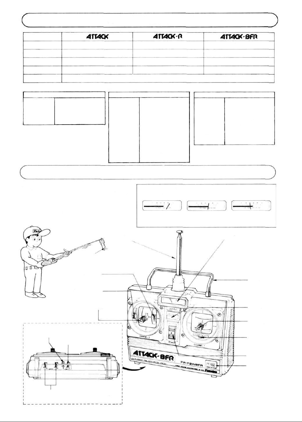
TRANSMITTER FP-T2NBL/T2NBR/T2NBFR
• Nomenclature
•The
name
of
each
part of
the
shown in the figure. Learn them before operating your set.
When running the vehicle, extend the antenna
fully.
transmitter
Receiving
frequency
Intermediate
frequency
Selectivity
Receiving range
Power supply
Dimensions
Weight
is
FP-T2NBR x 1
FP-R102GF x 1
FP-S128x2
R2-BSS-N x 1
Switch, frequency flag, spare horn
Ratings are subject to change without prior notice.
Receiver FP-R102GF
27MHz band. bands 1 to 6
72. 75MHz
455kHz
3kHz/-3dB
550 yards (500m) on the ground
when used with FP T2NBLIA1 the
best
radio
wave
condition
environment)
4.8V to 8 4V
7.2V/13mA. 4 8V/33mA
1.46 x2.19x0.75 in
(37 x 55.5 x 19mm)
1.34
oz
138g)
BEC & ASP functions
of
Before using the set, check the remaining
battery capacity by checking the level meter.
Good
FP-T2NBFR x 1
FP-R102GF x 1
FP-S128x 2
R2BSS-N x 1
Control system
Operating angle
Power
requirement
Current drain
(IDLE)
Output torque
Operating speed
Dimensions
Weight
SERVO FP-S128
pulse width control
One side 45° or more
4.8V
-6
6.0V. 8mA (at Idle)
48.7 oz.in. 13.5 kg-cm)
0.24 sec/60
16x08x 1.6 in.
(40.5 x 20 x 40.5mm)
1.92oz. 153g)
Caution No good
Change the battery.
Frequency flag
Neutral lever
Throttle trim
Throttle stick
ASP setting
trimmer
ASP setting
switch
(NEW ATTACK-BFR only)
Servo reverse switches
(NEW ATTACK-R, NEW ATTACK-BFR)
Antenna
Level meter
Handle
Hook
Steering stick
Steering trim
Power switch
Transmitter
crystal holder
2
Page 4
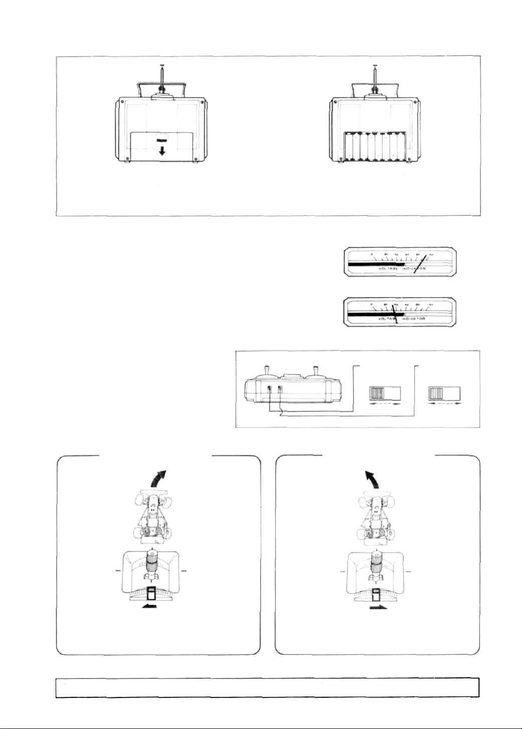
•LOADING THE PENLIGHT BATTERIES
• Remove the battery cover at the rear and insert eight penlight batteries in the correct polarity.
Remove the cover by push-
ing here and sliding down.
• Extend the antenna fully and set the power switch to ON.
The level meter pointer should deflect to the silver zone. If the pointer does not move, or moves very little, check for poor battery contact, incorrect battery polarity, or faulty batteries.
• If the pointer of the level meter deflects to the red zone, the range of
the radio waves will become short. When the pointer drops to the
boundary between the silver and red zones, change the batteries.
•The
trim
levers
are
used
to fine
adjust
the
used to adjust the neutral position and for correcting the running
steering
posture after the mechanism is mounted. After test running, make
corrections with the rod adjuster, etc. and operate the set with the
trim levers in the neutral position as much as possible.
angle.
They
•Servo reverse switches
(NEW ATTACK-R. NEW ATTACK-BFR)
• This switch makes servo rotation to anotherdirection.
• After fixed servos onto your model, and found
that rotation is wrong-way, switch to another
direction.
•Servo reverse switches are located at bottom of
Transmitter case like drawing below:
•Steering trim lever adjustment
When vehicle was run straight.
are
Load the eight pen-light
batteries while paying care-
ful attention to their-polarity.
Steering servo
reverse
switch
Normal Reverse
When vehicle was run straight •
Throttle
servo reverse
switch
Normal Reverse
When vehicle turns
to the right
Move the trim lever slowly
to the left so that the vehicle runs straight.
•Adjust the trim lever so that the vehicle runs straight on a smooth road.
The throttle trim lever is used to fine adjust the speed controller stop position, etc.
Move the trim lever slowly
to the right so that the
vehicle runs straight.
3
When vehicle turns
to the left
Page 5

•THROTTLE STICK NEUTRAL LEVER OPERATION
•The
neutral position of the throttle stick (engine
the neutral lever as shown in the figure.
When neutral
lever up
When neutral
lever down
control
stick)
at
the
left
side
can be
selected
in
two
stages
by
moving
If the neutral lever is moved, the
neutral position of the stick
lever can be adjusted in two
steps as shown in the figure.
When the neutral lever is up, the
throttle stick can be adjusted to
a total of 54°, 27" up and 27°
down, from the neutral position. This position is best for
electric cars and other models
with which the center of the
speed controller is the neutral
position.
•CHANGING THE THROTTLE STICK FROM A
SELF NEUTRAL SYSTEM TO A RATCHET
SYSTEM
•When changing the throttle stick from a self-neutral
system to a ratchet system, install the optional slider.
Then, remove the spring and swing arm.
Install the optional
slider.
Twist with long-nose
pliers.
Remove the
spring and
swing arm.
•CRYSTAL REPLACEMENT
•When changing the band, remove the crystal holder and
change the crystal. (Except 72. 75MHZ)
When the neutral lever is down,
the throttle stick can be adjusted to a total of 54°, 36° up
and 18° down (2-to-1), from the
neutral position. This position is
best for engine-drive cars or
other models with which the
speed controller neutral position
is offset.
•Futaba Digital Proportional Frequencies (FOR
U.S.A.)
• The frequency of Futaba digital proportional sets can be
changed among bands (1) ~ (6) on the 27MHz band only.
• However, a 27MHz band set cannot be changed to 72MHz
band, and vice versa.
• Therefore, always, attach the correct frequency flag to
the end of the transmitter antenna. Each frequency band
has its own designated color, as stated above. The frequency flag is intended for identification purposes.
• Also change the frequency flag when frequency is
changed.
• Futaba paired crystals are precisely matched. Always use
a Futaba crystal set (transmitter, receiver) when changing
the frequency.
• It is illegal to change crystals of transmitter on the 72-75
MHz bands in the U.S.A.
Frequency Channel No. Flag Color
•SWIVEL STICK SETTING
• To adjust the operating direction of the stick lever, loosen
the four screws shown in the figure and turn the stick
body and set it to the best position. After setting the
stick, retighten the four screws.
4
(1)
Loosen these four screws.
(3) Tighten these four
screws.
(2) Select the angle by
turning the stick body.
Stick lever can be set
within this range.
5°. 5°
Page 6

The
system
mark is displayed on the front of the receiver of BEC
sets
with a receiver
with
shared
power supply
regulator.
RECEIVER FP-R102GF AND SERVO FP-S128
Receiver crystal
Steering servo
Receiver FP-R102GF
Antenna wire
Red common 2P
connector (male pins)
Connect the servo and switch as
shown in the figure and extend
the transmitter and receiver antenna
fully.
(3) When
Red common 2P
connector
(Female pins)
motor
car
nary common power supply
chassis
Buy the red common 2P
connector from the kit
manufacturer and connect to
the controller.
Pin 1: Minus
Pin 2: Plus
uses
an
ordi-
ON
Switch
OFF
Connection to this connector
Red common
connector
(Female pins)
Red common 2P
connector
(Female pins)
Throttle servo
(1) When chassis power supply of
engine or motor car is separate
2P
(75MHz-OPTIONAL)
(2) When motor car uses a speci-
al BEC system chassis (common power supply specifications)
Controller
Connect to the red common
2P connector of the controller.
Wrapped with
rubber bands.
The Futaba BEC system and BEC & ASP system can also use a common power supply with the conventional four
penlight batteries system (separate power supply).
5
Page 7

•A common power supply regulator and diode may also be supplied with the speed controller, depending on the vehicle kit. Since they cause a voltage drop, always remove them.
TO BUYERS OF THE NEW ATTACK-BFR (FP-R102GF)
When using a Futaba motor control amp (MC-106,
106B, 108, 109, 110, etc.) instead of the speed
controller supplied with the vehicle, turn off the
ASP system as shown in the figure.
Insert the ASP release connector packed with the
set at this 2P connector '
(male pins) on the printed
wiring board.
•Set the transmitter power switch to ON, then set the receiver power switch to ON. The servos stop near the neutral
position. Operate the transmitter sticks and check if each servo faithfully follows operation of the sticks.
R102GF ASP
release
connector
From transmitter
when switch turned
on
• Connect the pushrod to each servo horn, then check if the direction of travel of each servo matches the transmitter
operation.
When transmitter
stick lever set to the
right
From receiver when
switch turned off
Vehicle also steers
to the right
6
Page 8

•Operate each servo over its full travel and check if the pushrod binds or is too loose. Applying unreasonable force to
the
servo
horn
will
•Always make the full stroke (including trim) of the servo horns somewhat larger than the full travel. Adjust the
servo horns so that they move smoothly even when the trim lever and stick are operated simultaneously in the same
direction.
•
Be
alert for noise.
Always solder a noise killing capacitor to the running motor. If metal parts touch each other due to vibration, noise
will
be generated and
•Even
though the receiver antenna
adversely
cause
affect
the
the receiver
wire
servo
and quickly drain
servos
to
is
long,
do
the
operate erroneously.
not
cut
or
bundle
battery.
We
recommend the
it.
The
range
Be
especially
of
the
radiowaves
careful
use
of
when using
noiseless
will
8.4V.
parts.
be shortened.
Receiver antenna
wire
R102GF
Scissors
Install
the
servos
the servo to the servo tray as
shown in the figure. In other
cases, install the servo as described in the model manufacturer's manual.
• A spare horn is provided. Use it as required.
•Wrap
the receiver
not exposed to vibration, does not touch the frame, and does not move.
•When
the
bag, etc. and wrap a rubber band around the open end of the bag to waterproof and dustproof the receiver. After use,
remove the receiver from the bag to prevent condensation.
• Use the rubber bands wrapped around the receiver to hold the servo and switch leads.
•After mounting is complete, recheck each part, then check the transmitting range by making the transmitter antenna
as short as possible and extending the receiver antenna fully and operating the set from a distance of 20m to 30m. The
movement of each servo should follow the movement of the transmitter sticks.
• The crystal can be changed from the outside of the receiver case. Always use a Futaba transmitter and receiver crystal
pair as the replacement crystals.
receiver
in
sponge
rubber and
is
installed on a board or
wrap
used
rubber
where
bands
it
may
around
be
the
sponge
splashed
with
rubber.
mud
firmly.
Mount the
and
water,
Wood screw
Rubber bushing
Grommet
Install
receiver
place
it
in a plastic
so
•USING THE FREQUENCY FLAG
it
is
Insert the frequency flag
into the flag holder as
shown here.
72/75MHZ Flag
Staple or glue with cyanoacrylate ribbon here.
• The hook is for the optional neck strap. It is convenient when hanging the transmitter from your neck.
The flag can be attached to
and removed from the end
of the antenna with one
touch.
7
Page 9

The BEC system that makes it easy even for beginners to lighten the vehicle by means of a shared power supply is already well known. The unique
Futaba
ASP
system
is
built
into
the
BF
series
was
completed by
advancing this BEC system one more step and pursuing greater safety.
ASP detects a drop in the voltage and moves the throttle servo automatically to the drive motor off position which is preset at the transmitter
before steering control is lost by a drop in the Nicd battery voltage while
the vehicle is running. It is also the world's first revolutionary system that
allows steering operation with the remaining power.
(Patent pending)
•ASP setting (NEW ATTACK-BFR only)
Before running, set ASP to the controller stop posi-
tion.
• If the controller is not set to the stop position, when the
running Nicd battery voltage drops, the throttle servo
may stop at a position other than the stop position and
the vehicle may run wild because the throttle servo cannot be controlled from the transmitter.
1. Set the transmitter and receiver power switches to on
and check the steering and throttle operations.
2. a) Set the ASP setting switch to the SET side. ASP setting
b) Turn the ASP setting trimmer at the left
switch with a little screwdriver.
c) Since this moves the throttle
stops at the stop position of the connected controller.
3. Then complete adjustment by setting the ASP setting
switch to the NORM side. (If the switch is not switched
to the NORM side, the throttle servo will not be controlled by the throttle stick.)
servo, set so that it
side of the
Since the stop position
differs with the chassis
manufacturer, check it
when connecting the
linkage.
trimmer
NORM
Forward
Throttle
servo
NORM
ASP
SET
When setting ASP
Stop
SET
Reverse
Controller
ASP setting
switch
NORM
When ASP setting is
complete
When the ASP setting
trimmer is turned in the
arrow direction, the
throttle servo turns in
this direction.
Turn
with a little
driver
• When the Nicd battery voltage drops, the throttle servo is moved to the preset position and the drive motor is stopped
automatically.
screw-
Throttle servo
8
Page 10

•STARTING
When the ASP operates and the vehicle
stops as soon as it starts to run, there is
trouble somewhere.
•Since the vehicle, running Nicd battery,
motor, etc. is abnormal when ASP was
operated, check again.
•IF ASP OPERATES
(Vehicle trouble)
•If
something gets caught in the gears or the
tires do not rotate smoothly and an overcurrent flows in the motor, ASP may operate.
When using the common power supply diode
and regulator with a vehicle without BEC specifications. release ASP. Otherwise, ASP will
operate immediately.
•Since the Futaba and FP-R102GF receivers
have the BEC system built into them,
a diode and regulator are not connected.
(Running Nicd battery trouble)
•When the Nicd battery is charged insufficiently or is old, ASP will operate.
Insufficient charge
(Motor trouble)
•When a modified motor, high power motor,
or a motor whose angle cannot be adjusted
is used and when the motor is accelerated and
reversed suddenly, ASP may operate.
•When using high power motor, set ASP to
OFF with ASP release connector. But when
setting ASP to OFF, be careful that the ve-
hicle may run away if the capacity of running Nicd battery runs short.
Capacity of used
Nicd is low.
R102GF
release
connector
ASP
Insert the ASP release connector
packed with the set at this 2P
connector (male pins) on the
printed wiring board.
9
Page 11

•IF ASP OPERATES
• If ASP system operates and the vehicle stops.
set the transmitter power switch to OFF
once and set it to ON again. Then ASP
system
stops working and you can start again.
• Restart running time depends on the variety
and condition of vehicle, motor, and battery.
Be careful about that.
•WHEN VEHICLE WILL NOT BE USED
Be sure and release the connector of running
Nicd battery except when you are on the way
to the starting line.
Set to OFF once
When not using the
connector, set the
switch to OFF.
ON
OFF
Set to ON again.
Release the connector.
FP-S128
No.
1.
2
3.
4.
5.
6.
7.
8.
9.
10
11.
12.
13.
14.
15.
16
17.
18.
19.
20.
21.
22.
The following splined horns are optional.
Part Name
Upper case
Middle case
Bottom case
Metal bearing
Potentiometer
VR drive plate
Motor
Motor pinion
Motor mounting
screw 2x3
1st gear
2nd gear
3rd gear
Final gear
Intermediate shaft
2nd shaft
Servo horn D
Horn mounting screw
2.6x8
Printed wiring board
S128...3PBWRB300
Lead wire packing
Case mounting screw
Nameplate
Part No.
FCS28
S04134
139995
S02753
S91212
S02461
J
50002
FGS-28
S02495
S02494
FSH-6W
FSH-41
AS1202
FPC-8M
S90045
J50400
S80700
•SPLINED HORNS
This horn permits shifting of the
servo neutral position at the servo
horn. Setting and shifting the neutral
position
a)
Angle divisions
1) The splined horn has 25 segments. The amount of change per
segment is; 360-25=14.4°
2) The minimum adjustable angle is
determined by the number of arms or
number of the holes. For four arms,
the minimum adjustable angle is:
b) Effect
To shift the holes center line to the
right (clockwise) relative to baseline
A, shift arm 2 to the position of arm
1 and set it to the position closet to
baseline A.
[Example] For a four arm horn, the
angular shift per segment is 14.4°.
The shift to the right is 90° - (14.4 /
6) = 3.6°
To shift by the same angle in
opposite direction, use the opposite
arm number.
For a six arm horn, turn the arm
counterclockwise and set arm 2 to
the position of arm 1. The adjustable
angle is 60° - (14.4 x 4) = 2.4°.
Arm 3 shift 4.8° to the right, arm 6
shifts 2.4° to the left, and arm 4
shifts 7.2° to the right and left.
the
HORN A HORN B HORNC HORN D HORN E HORN F
10
Page 12

Your NEW FUTABA Digital Proportional R/C system
is guaranteed against defects in workmanship and
material for 180 days from the date of purchase when
the attached registration card is returned to us within
ten days of purchase.
This Guarantee is null and void if the R/C system has
been improperly handled, damaged in a crash, or
tampered with and does not cover the replacement of
plastic housings or electronic components damaged
due to the use of improper voltages.
When service is required, please take your equipment
to your local authorized service station or ship it
directly to us. All postage, shipping, and insurance
charges must be paid by the user.
WORLD SALES & SERVICE FACILITIES
•When requesting repair of trouble that has occurred
suddenly of from long use, describe the trouble
symptoms in as much detail as possible.
This will facilitate detection of the trouble point and
shorten the repair period greatly.
•Defects caused by faulty materials or workmanship
will be corrected free of charge.
•This limited warranty is null and void if the set has
been tampered with or disassembled.
Refer to warranty statement for details.
Australia: FUTABA SALES AUSTRALIA PTY. LTD., Lebanon:
Argentine: MODE LISMO AERONAUTICO DEGA SRL. New Zealand:
Canada: UDISCO LTD., MONTREAL
Chile: HOBBY LANDIA, SANTIAGO
Denmark: FUTABA IMPORT DENMARK,
England: RIPMAX LIMITED, LONDON
Finland: NORETRON KY. HELSINKI
Greece: C. & G. MACRIYIANNIS CO., PIRAEUS
Hong Kong: RADAR CO. LTD. TEL: 3-680507
Italy: RADIOSISTEMI SRL, Carrara W.Germany:
MELBOURNE TEL: 211-4788
BUENOS AIRES TEL: 393-2299
TEL: 481-8109 Norway:
TEL: 743957 Singapore:
COPENHAGEN TEL: 02-91-0101 South Africa:
TEL: 01-8048272 Spain:
TEL: 90-488880 Sweden:
TEL: 021-3604 391 • or 021-41 76191 U.S.A.:
TLX: 500494 FORTIMI
FAX: 0039-585-52247
KHAIRALLAH MODELCRAFT, BEIRUT
TEL: 326-681
AMALGAMATED WIRELESS
(AUSTRALIA) N.Z. LTD. WELLINGTON
TEL: 58-979
HARALD LYCHE CO. A/S, Drammen
TEL: (03) 833970
SINGAPORE HOBBY SUPPLIES
TEL: 533-0337
REDIPAK (PTY.) LTD.,
JOHANNESBURG TEL: 21-1511
HOBBY & TOY INTERNATIONAL,
VALENCIA TEL: (96) 357 23 93
RADIO CONTROL CENTER,
JONKOPING TEL: 036-145360
FUTABA CORPORATION OF AMERICA,
CALIFORNIA TEL: 213-537-9610
ROBBE MODELLSPORT GMBH,
GREBENHAIN TEL: 06644-870
FUTABA
555 West Victoria Street Compton, California 90220 U.S.A.
Phone: (213) 537-9610 Telex: 23-0691227 Facsimile: 213-637-8529
FUTABA
Tokyo Office: INAGAKI BLDG., 3F 1-21-3, Kandasudacho, Chiyoda-ku,
Phone: (03) 255-6811
CORPORATION
CORPORATION
Tokyo,Japan.
OF
AMERICA
 Loading...