


OPERATOR'S MANUAL
MULTI-COLOR LCD RADAR
FR-8045
FR-8065
FR-8125
Model
PRODUCT NAME: MARINE RADAR
FR-8255
www.furuno.com

The paper used in this manual
9-52 Ashihara-cho,
A:JAN
2014
.
A5:AUG.22, 2014
Pub. No.
(
)
Nishinomiya, 662-8580, JAPAN
is elemental chlorine free.
・FURUNO Authorized Distributor/Dealer
All rights reserved.
AKMU
FR-8045/8065/8125
Printed in Japan
OME-36320-A5
0 0 0 1 7 8 5 0 2 1 0
IMPORTANT NOTICES
General
• This manual has been authored with simplified grammar, to meet the needs of international users.
• The operator of this equipment must read and follow the descriptions in this manual. Wrong operation or maintenance can cancel the warranty or cause injury.
• Do not copy any part of this manual without written permission from FURUNO.
• If this manual is lost or worn, contact your dealer about replacement.
• The contents of this manual and equipment specifications can change without notice.
• The example screens (or illustrations) shown in this manual can be different from the screens you
see on your display. The screens you see depend on your system configuration and equipment
settings.
• Save this manual for future reference.
• Any modification of the equipment (including software) by persons not authorized by FURUNO will
cancel the warranty.
• All brand and product names are trademarks, registered trademarks or service marks of their respective holders.
• Ricoh bitmap font is a trademark or registered trademark of Ricoh Company, Ltd.
How to discard this product
Discard this product according to local regulations for the disposal of industrial waste. For disposal
in the USA, see the homepage of the Electronics Industries Alliance (http://www.eiae.org/) for the
correct method of disposal.
How to discard a used battery
Some FURUNO products have a battery(ies). To see if your product has a battery, see the chapter
on Maintenance. Follow the instructions below if a battery is used. Tape the + and - terminals of
battery before disposal to prevent fire, heat generation caused by short circuit.
In the European Union
The crossed-out trash can symbol indicates that all types of batteries
must not be discarded in standard trash, or at a trash site. Take the
used batteries to a battery collection site according to your national
legislation and the Batteries Directive 2006/66/EU.
In the USA
The Mobius loop symbol (three chasing arrows) indicates that Ni-Cd
and lead-acid rechargeable batteries must be recycled. Take the used
batteries to a battery collection site according to local laws.
Ni-Cd Pb
In the other countries
Cd
There are no international standards for the battery recycle symbol. The number of symbols can
increase when the other countries make their own recycle symbols in the future.
i
SAFETY INSTRUCTIONS
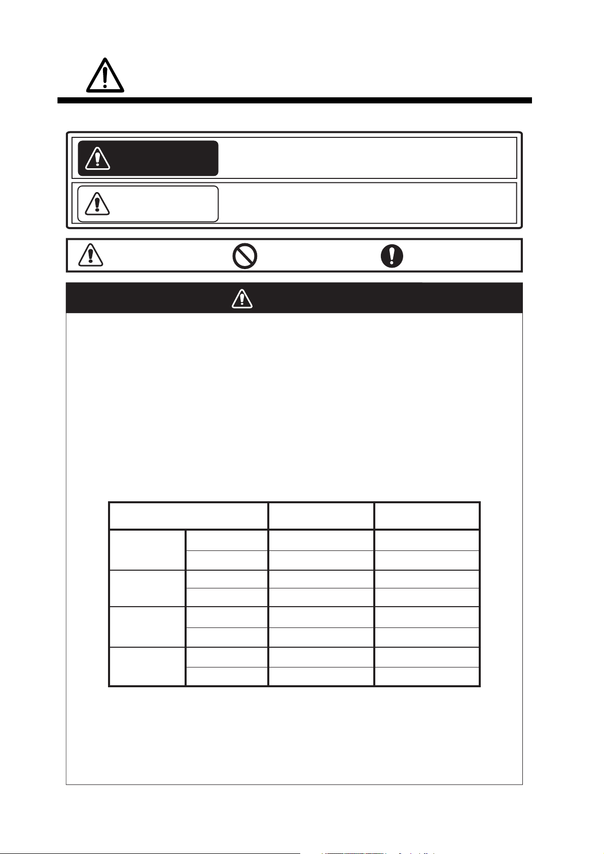
Read these safety instructions before you operate the equipment.
Indicates a condition that can cause death or serious
WARNING
CAUTION
injury if not avoided.
Indicates a condition that can cause minor or moderate
injury if not avoided.
Warning, Caution
Prohibitive Action
Mandatory Action
WARNING
Radio Frequency Radiation Hazard
The radar antenna sends the electromagnetic radio frequency (RF) energy. This energy
can be dangerous to you, especially your eyes. Do not look at the radiator or near the
antenna when the antenna is rotating.
2
The distances at which RF radiation levels of 100 W/m
the table.
Note: If the antenna unit is installed at a close distance in front of the wheel house,
prevent the transmission in that area to protect passengers and crew from microwave
radiation. Set the [Sector Blanks] in the [System] menu.
Model
XN-12A
FR-8045
XN-13A
100W/m
N/A
N/A
and 10 W/m2 exist are shown in
2
10W/m
2
1.1m
1.0m
FR-8065
XN-12A
XN-13A
XN-12A
FR-8125
XN-13A
XN-12A
FR-8255
XN-13A
N/A
N/A
N/A
N/A
0.6m
0.4m 3.1m
1.9m
1.7m
2.1m
1.9m
4.6m
ii
SAFETY INSTRUCTIONS
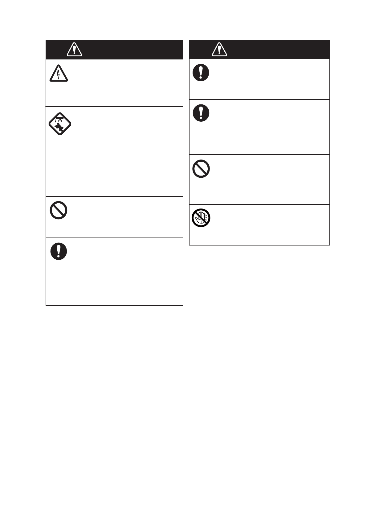
WARNING
ELECTRICAL SHOCK HAZARD
Do not open the equipment.
Only qualified persons can work
inside the equipment.
Turn off the power before you
service the antenna unit. Post a
warning sign near the power
switch not to turn on the power
while you service the antenna
unit.
Prevent the potential risk of being
struck by the rotating antenna and
exposure to RF radiation hazard.
Do not disassemble or modify
the equipment.
Fire or electrical shock can occur.
Turn off the power immediately
if water leaks into the equipment
or smoke or fire is coming
from the equipment.
WARNING
Use the correct fuse.
A wrong fuse can damage the
equipment and cause fire.
Keep heater away from the
equipment.
Heat can change the equipment
shape and melt the power cord, which
can cause fire or electrical shock.
Do not put liquid-filled containers
on the top of the equipment.
Fire or electrical shock can occur if a
liquid spills into the equipment.
Do not operate the equipment with
wet hands.
Electrical shock can occur.
Failure to turn off the equipment
can cause fire or electrical shock.
iii
SAFETY INSTRUCTIONS
CAUTION
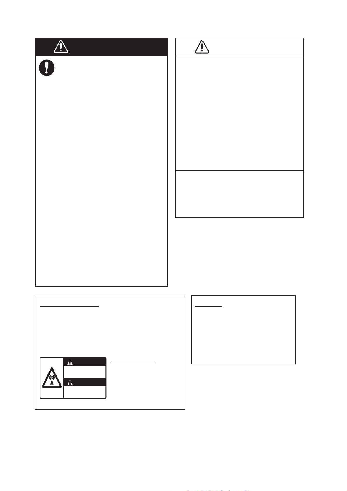
WARNING
Do not depend on one navigation
device for the navigation of the
ship. The navigator must check all
aids available to confirm position.
Electronic aids are not a
replacement for basic navigation
principles and common sense.
· The ARPA automatically tracks an
automatically or manually acquired
radar target and calculates its
course and speed, indicating them
by a vector. Since the data from the
auto plotter depend on the selected
radar targets, the radar must be
optimally tuned for use with the auto
plotter, to ensure required targets
will not be lost or unnecessary
targets like sea returns and noise
will not be acquired and tracked.
· A target is not always a landmass,
reef, ship, but can also be returns
from the sea surface and from
clutter. As the level of clutter
changes with the environment, the
operator must correctly adjust the
A/C SEA, A/C RAIN and GAIN
controls so that the target echoes do
not disappear from the radar screen.
CAUTION
The tracking accuracy is affected by the
following:
· The tracking accuracy is affected by
course change. One to two minutes is
required to restore vectors to full
accuracy after a sudden course change.
(The actual amount depends on
gyrocompass specifications.)
· The amount of tracking delay is inversely
proportional to the relative speed of the
target. Delay is on the order of 15-30
seconds for high relative speed; 30-60
seconds for low relative speed.
The data from ARPA and AIS are
intended for reference purposes only.
Check all available navigation aids to
determine target movement.
WARNING LABELS
Warning labels are attached to the equipment.
Do not remove any label. If a label is missing or
damaged, contact a FURUNO agent or dealer
about replacement.
WARNING
Radiation hazard. Only qualified
personnel should work inside scanner.
Confirm that TX has stopped before
opening scanner.
ANTENNA UNIT
Name: Warning Sticker
Type:
Code No.: 100-266-890-10
03-142-3201-0
TFT LCD
The high quality TFT (Thin Film
Transistor) LCD displays 99.999%
of its picture elements.
The remaining 0.001% may drop
out or light, however this is an
inherent property of the LCD; it is
not a sign of malfunction.
iv

TABLE OF CONTENTS
FOREWORD................................................................................................................... ix
SYSTEM CONFIGURATION .......................................................................................... xi
1. OPERATION ..........................................................................................................1-1
1.1 Controls ......................................................................................................................1-1
1.2 How to Turn the Radar On/Off and Transmit..............................................................1-2
1.3 Display Indications......................................................................................................1-3
1.4 How to Adjust Display Brilliance, Panel Dimmer ........................................................1-4
1.5 Menu Description........................................................................................................1-4
1.6 Tuning.........................................................................................................................1-6
1.7 Display Modes............................................................................................................1-7
1.7.1 How to select the display mode......................................................................1-7
1.7.2 Description of display modes .........................................................................1-8
1.8 How to Select a Range Scale...................................................................................1-10
1.9 How to Adjust the Gain (sensitivity)..........................................................................1-10
1.10 How to Reduce the Sea Clutter................................................................................1-11
1.11 How to Reduce the Rain Clutter...............................................................................1-12
1.12 Automatic Adjustments of Sea and Rain Clutters.....................................................1-13
1.13 Cursor.......................................................................................................................1-14
1.14 Interference Rejector................................................................................................1-15
1.15 How to Measure the Range to a Target ...................................................................1-16
1.15.1 How to adjust range ring brilliance ...............................................................1-16
1.15.2 How to measure the range with a VRM........................................................1-17
1.15.3 How to select VRM unit ................................................................................1-17
1.16 How to Measure the Bearing to a Target..................................................................1-18
1.16.1 How to measure the bearing with an EBL ....................................................1-18
1.16.2 EBL reference ..............................................................................................1-19
1.17 How to Measure the Range and Bearing Between Two Targets .............................1-19
1.18 How to Select a Pulselength.....................................................................................1-20
1.19 Target Alarm.............................................................................................................1-21
1.19.1 How to set a target alarm zone ....................................................................1-21
1.19.2 How to stop the audio alarm.........................................................................1-22
1.19.3 How to select the alarm type ........................................................................1-22
1.19.4 How to sleep a target alarm temporarily.......................................................1-23
1.19.5 How to deactivate a target alarm..................................................................1-23
1.19.6 How to select the target strength which triggers a target alarm ...................1-23
1.19.7 How to turn the buzzer on/off .......................................................................1-23
1.20 How to Off-center the Display...................................................................................1-24
1.20.1 How to select the off-center mode................................................................1-24
1.20.2 Off-center the display ...................................................................................1-24
1.21 Zoom ........................................................................................................................1-26
1.21.1 Zoom mode ..................................................................................................1-26
1.21.2 How to zoom ................................................................................................1-26
1.22 Echo Stretch.............................................................................................................1-28
1.23 Echo Average...........................................................................................................1-28
1.24 Target Trails .............................................................................................................1-29
1.24.1 Trail time.......................................................................................................1-29
1.24.2 How to start, stop the trails...........................................................................1-30
1.24.3 Trail mode ....................................................................................................1-30
1.24.4 Trail gradation ..............................................................................................1-31
1.24.5 Trail color......................................................................................................1-31
1.24.6 Trail level ......................................................................................................1-32
v

TABLE OF CONTENTS
1.24.7 How to restart, stop the trails ....................................................................... 1-32
1.24.8 Narrow trails ................................................................................................. 1-33
1.24.9 Your ship trail ...............................................................................................1-33
1.25 How to Send the Target Position and Enter the Origin Mark ................................... 1-33
1.26 How to Hide the Heading Line Temporarily ............................................................. 1-34
1.27 Presentation Brilliance ............................................................................................. 1-34
1.28 Custom Setup .......................................................................................................... 1-34
1.28.1 About custom setup ..................................................................................... 1-34
1.28.2 Description of custom setup items ............................................................... 1-35
1.28.3 How to set custom setups............................................................................ 1-36
1.29 How to Program Function Keys (F1, F2 and F3 keys)............................................. 1-37
1.30 Noise Rejector..........................................................................................................1-38
1.31 Wiper........................................................................................................................ 1-38
1.32 How to Reduce Second-trace Echoes ..................................................................... 1-39
1.33 Watchman ................................................................................................................ 1-39
1.34 Color Selections ....................................................................................................... 1-40
1.34.1 Preset colors ................................................................................................1-40
1.34.2 Custom colors ..............................................................................................1-41
1.35 Navigation Data........................................................................................................1-42
1.35.1 Navigation data during standby....................................................................1-42
1.35.2 Navigation data at the bottom of the screen ................................................ 1-42
1.36 Dynamic Range........................................................................................................1-43
1.37 Characteristics Curve...............................................................................................1-44
1.38 Waypoint Marker ...................................................................................................... 1-45
1.39 Alarm Message ........................................................................................................ 1-45
1.40 Echo Area ................................................................................................................ 1-47
1.41 Initial Sub Menu ....................................................................................................... 1-48
1.41.1 How to open the Initial sub menu................................................................. 1-48
1.41.2 Description of Initial sub menu..................................................................... 1-48
1.42 Units Sub Menu........................................................................................................1-50
1.43 Sector Blank.............................................................................................................1-51
1.44 Other Menu Items .................................................................................................... 1-52
1.44.1 Menu items on the [Brill/Color] menu........................................................... 1-52
1.44.2 Menu items on the [Display] menu............................................................... 1-53
1.44.3 Menu items on the [Echo] menu ..................................................................1-53
1.45 Remote Display........................................................................................................1-54
2. DESCRIPTION OF RADAR ...................................................................................2-1
2.1 General ......................................................................................................................2-1
2.1.1 Minimum and maximum ranges..................................................................... 2-1
2.1.2 Radar resolution.............................................................................................2-2
2.1.3 Bearing accuracy ........................................................................................... 2-3
2.1.4 Range measurement...................................................................................... 2-3
2.2 False Echoes ............................................................................................................. 2-3
2.2.1 Multiple echoes ..............................................................................................2-3
2.2.2 Sidelobe echoes............................................................................................. 2-4
2.2.3 Virtual image ..................................................................................................2-4
2.2.4 Shadow sector ............................................................................................... 2-5
2.3 SART (Search and Rescue Transponder) ................................................................. 2-5
2.3.1 SART description ...........................................................................................2-5
2.3.2 General remarks on receiving SART ............................................................. 2-6
2.4 RACON ...................................................................................................................... 2-6
vi

TABLE OF CONTENTS
3. ARPA OPERATION...............................................................................................3-1
3.1 Precautions for Use....................................................................................................3-1
3.2 Controls for Use with ARPA .......................................................................................3-1
3.3 ARPA Display On/Off .................................................................................................3-2
3.4 How to Acquire and Track the Targets.......................................................................3-2
3.4.1 Manual acquisition..........................................................................................3-2
3.4.2 Automatic acquisition .....................................................................................3-3
3.5 How to Stop the Tracking of ARPA Target.................................................................3-3
3.5.1 How to stop the tracking of selected targets ..................................................3-3
3.5.2 How to stop the tracking of all targets ............................................................3-3
3.6 Vector Attributes.........................................................................................................3-4
3.6.1 What is a vector?............................................................................................3-4
3.6.2 Vector time and vector reference ...................................................................3-4
3.6.3 Vector of your ship .........................................................................................3-5
3.7 History Display (target past position)..........................................................................3-6
3.8 ARPA Target Data......................................................................................................3-7
3.9 CPA/TCPA Alarm .......................................................................................................3-8
3.10 Proximity Alarm ..........................................................................................................3-9
3.11 Lost Target .................................................................................................................3-9
3.12 Symbol Color............................................................................................................3-10
4. AIS OPERATION ...................................................................................................4-1
4.1 Controls for Use with AIS ...........................................................................................4-1
4.2 AIS Display On/Off .....................................................................................................4-1
4.3 AIS Symbols...............................................................................................................4-2
4.4 Activating, Sleeping Targets.......................................................................................4-2
4.5 AIS Target Data..........................................................................................................4-3
4.6 How to Sort Targets....................................................................................................4-4
4.7 Display Range ............................................................................................................4-4
4.8 How to Display the Targets within a Specific Sector ..................................................4-5
4.9 Number of Targets to Display.....................................................................................4-5
4.10 Vector Attributes.........................................................................................................4-6
4.10.1 What is a vector?............................................................................................4-6
4.10.2 Vector time and vector reference ...................................................................4-6
4.11 History Display (target past position)..........................................................................4-7
4.12 CPA/TCPA Alarm .......................................................................................................4-8
4.13 Proximity Alarm ..........................................................................................................4-9
4.14 Lost Target .................................................................................................................4-9
4.15 Symbol Color............................................................................................................4-10
4.16 How to Ignore Slow Targets .....................................................................................4-10
5. GPS OPERATION .................................................................................................5-1
5.1 Navigator Mode ..........................................................................................................5-1
5.2 Datum.........................................................................................................................5-1
5.3 WAAS Setup...............................................................................................................5-2
5.4 Satellite Monitor..........................................................................................................5-3
5.5 Cold Start....................................................................................................................5-4
vii

TABLE OF CONTENTS
6. MAINTENANCE, TROUBLESHOOTING...............................................................6-1
6.1 Preventative Maintenance..........................................................................................6-2
6.2 Fuse Replacement ..................................................................................................... 6-2
6.3 Magnetron Life ........................................................................................................... 6-3
6.4 LCD Backlight Life......................................................................................................6-3
6.5 Simple Troubleshooting ............................................................................................. 6-4
6.6 Advanced-level Troubleshooting................................................................................ 6-5
6.7 Diagnostic Test ..........................................................................................................6-6
6.8 LCD Test .................................................................................................................... 6-8
6.9 ARPA Test ................................................................................................................. 6-9
6.10 GPS Test..................................................................................................................6-10
APPENDIX 1 MENU TREE .......................................................................................AP-1
APPENDIX 2 GEODETIC CHART LIST ...................................................................AP-5
SPECIFICATIONS .....................................................................................................SP-1
INDEX..........................................................................................................................IN-1
Declaration of Conformity
viii

FOREWORD
A word to the Owner of the FR-8045/FR-8065/FR-8125/FR-8255 Multicolor LCD Radar.
Congratulations on your choice of the FURUNO FR-8045/FR-8065/FR-8125/FR-8255 Multi-color
LCD Radar. We are confident you will see why the FURUNO name has become synonymous with
quality and reliability.
Since 1948, FURUNO Electric Company has enjoyed an enviable reputation for innovative and
dependable marine electronics equipment. This dedication to excellence is furthered by our extensive global network of agents and dealers.
This equipment is designed and constructed to meet the rigorous demands of the marine environment. However, no machine can perform its intended function unless installed, operated and
maintained properly. Please carefully read and follow the recommended procedures for operation
and maintenance.
We would appreciate feedback from you, the end-user, about whether we are achieving our purposes.
Thank you for considering and purchasing FURUNO equipment.
Features
The FR-8045/FR-8065/FR-8125/FR-8255 series displays ships, land masses, etc. on a LCD
screen. This equipment can be operated using the keys, knob controls or the Cursorpad.
The main features are listed below.
• Bright 12.1-inch LCD, visible in direct sunlight.
• Easy to understand user interface with on-screen menus.
• Full-screen Echo area display provides a wider range around the vessel.
• User-programmable function keys.
• Optional Auto Plotter ARP-11 is available for ARPA operation.
• AIS data can be displayed with the connection of a FURUNO AIS Transponder/Receiver.
• Echoes can be displayed multiple colors.
Note: The Chinese font used in this equipment is Ricoh Company Ltd.’s Ricoh bitmap font.
ix

FOREWORD
Radar Type and Function Availability
This radar series is available in four types: [River], [Sea], [IEC] and [Russian-River], and function
availability depends on type. The table below shows type and function availability.
[River]: For river, [Sea]: For sea, [IEC]: IEC compliant radar, [Russian-River]: For Russian river
Type and function availability
Item Type
River Sea IEC Russian-River
Automatic menu
closure
Effective radius
dot count
Echo color Select the echo display color among
Echo color customizing
Echo area Select the display area from [Normal]
Base text display Can show or hide the base text indi-
Range preset Select the radar ranges to use. Can not select
Unit defaults 1)
range 2) speed
Bearing scale Graduation every 1°, 5°, 10°, 30°, no
VRM unit Can set the VRM unit independently
Range unit Can change the range unit when
AIS symbol color Select the AIS symbol color from
Vector reference Select the display mode for the vector
Pulselength • 2NM/4KM/2SM: MP
The rule for the
numbering of
ARPA targets
Marks temporary
hidden by pressing and holding
the CANCEL/HL
OFF key
Menu does not close automatically. Menu closes automatically when
there is no menu operation for 10
seconds.
300 dots 262 dots
Select the echo display color among
[Yellow], [Green], [Orange] or [Multi].
Can customize the echo display col-
or.
or [Full Screen].
cations.
1) KM 2) km/h,
m/s
numeric indication, displayed in the
effective radius
from the range unit.
transmitting.
[Green], [Red], [Blue], [White] or
[Black].
from [Relative] or [True].
• 4NM/8KM/4SM: LP
Non-IEC system IEC system
Heading line, all marks (EBL, VRM,
target alarm zone, etc.)
1) NM 2) kn 1) KM 2) km/h,
[Yellow], [Green] or [Orange].
Can not customize the echo display
color.
Can not select. Display area is circle
only.
Can not hide the base text indica-
tions.
the radar ranges
to use.
m/s
Graduation every 1°, 5°, 10°, 30°, numeric indication every 30°, displayed
out of the effective radius
Can not set the VRM unit independently from the range unit.
Can not change the range unit in
transmit. Only in standby.
Select the AIS symbol color from
[Green], [Blue], [White] or [Black].
[True]
• 2NM/4KM/
2SM: SP or
MP
• 4NM/8KM/
4SM: MP or LP
Heading line, vector of your ship (with
ARP-11)
x
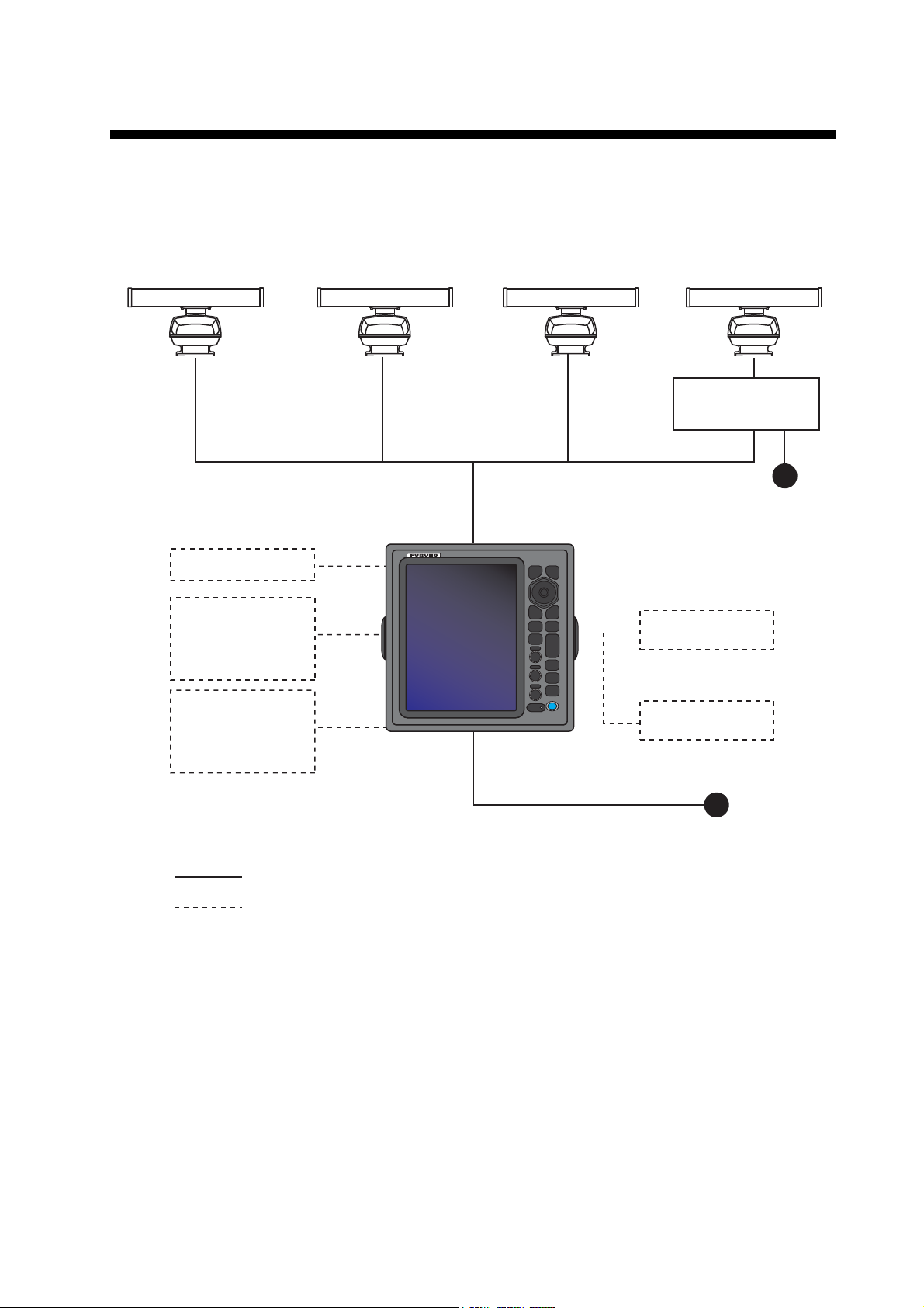
SYSTEM CONFIGURATION
Model FR-8045
Antenna Unit
XN-12A-RSB-0073-088B
XN-13A-RSB-0073-088B
Heading sensor
Echo sounder
GPS navigator
AIS, etc.
Model FR-8065
Antenna Unit
XN-12A-RSB-0070-085A
XN-12A-RSB-0073-085A
XN-13A-RSB-0070-085A
XN-13A-RSB-0073-085A
Model FR-8125
Antenna Unit
XN-12A-RSB-0070-086A
XN-12A-RSB-0073-086A
XN-13A-RSB-0070-086A
XN-13A-RSB-0073-086A
Display unit
RDP-154
Model FR-8255
Antenna Unit
XN-12A-RSB-0070-087A
XN-12A-RSB-0073-087A
XN-13A-RSB-0070-087A
XN-13A-RSB-0073-087A
Antenna Power Supply
PSU-008
24 VDC
Remote display
Echo sounder
GPS navigator
AIS, etc.
: Basic configuration
: Optional
External buzzer
24 VDC
xi

SYSTEM CONFIGURATION
This page is intentionally left blank.
xii
1. OPERATION
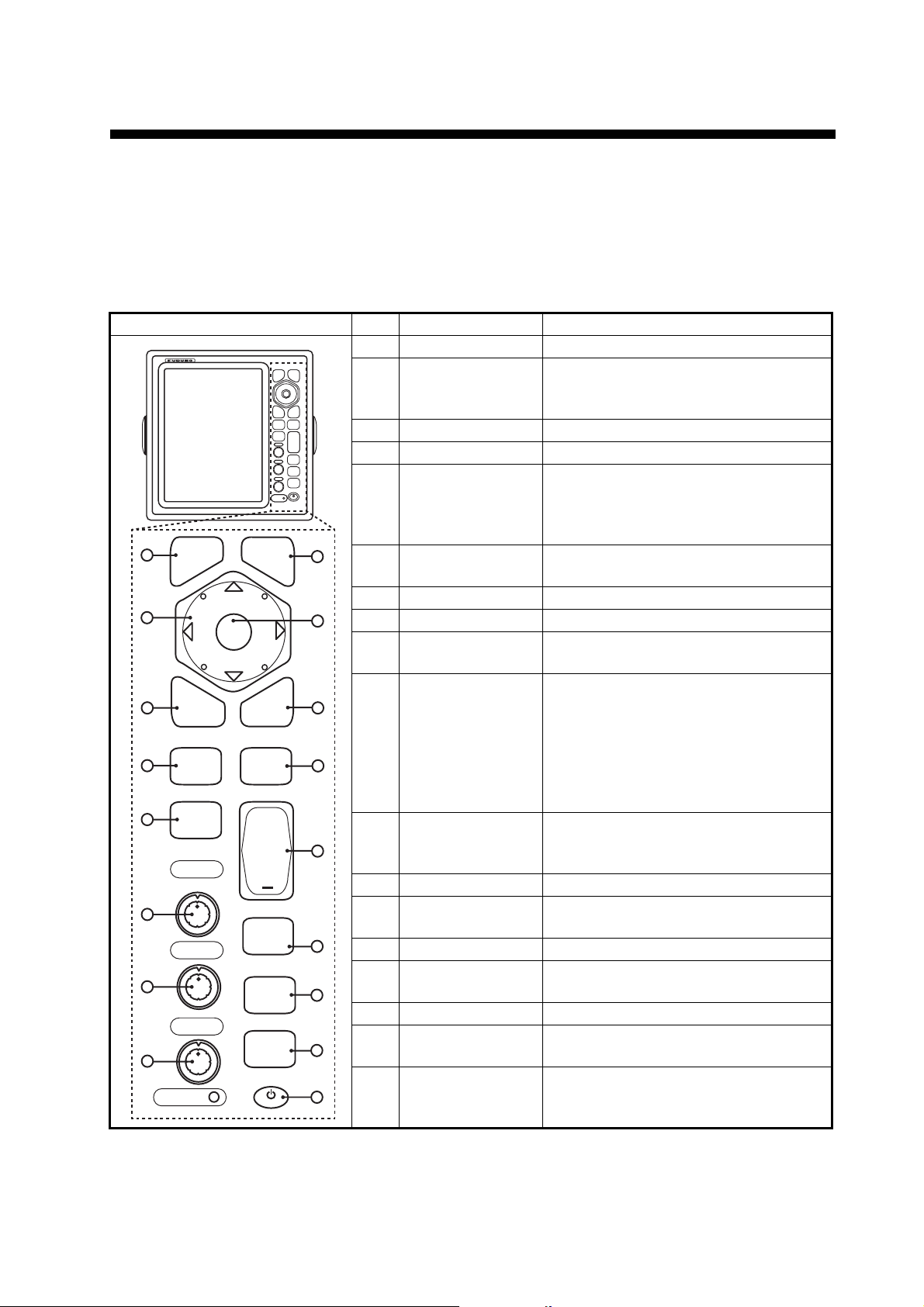
1.1 Controls
The display unit has 16 keys which have labels with their functions, three knob controls and a CursorPad. When you correctly operate this equipment, the unit beeps one
time. If your operation is not correct, the unit beeps three times.
No. Control Description
1 MENU Open/close the menu.
2 CursorPad Select the menu items and options.
3 EBL Measure the bearing to a target.
4 OFF CENTER Off-center the display.
5 TLL Send the latitude and longitude of a
9
6 GAIN Rotating: Adjust the sensitivity of the
7 A/C SEA Rotating: Reduce the sea clutter.
8 A/C RAIN Rotating: Reduce the rain clutter.
6,7,8F1,F2, F3 Push: Activate the function given to
9 CANCEL/HL
11
12
OFF
10 ENTER Save selected menu option. Acquire
13
11 VRM Measure the range to a target.
12 TARGET
ALARM
14
13 RANGE Select the detection range.
14 CUSTOM Set the radar controls for one-touch
15
15 TRAILS Plot the radar echo movement.
16 STBY/TX Transmit the radar pulses or put the
17 Brill Short Press: Turn on the power. Adjust
1
2
3
4
5
F1
6
F2
7
F3
8
ECONOMY
MENU
EBL
OFF
CENTER
TLL
GAIN
A/C SEA
A/C RAIN
ENTER
MENU
EBL VRM
OFF
CENTER
TLL
GAIN
A/C SEA
A/C RAIN
ECONOMY
CANCEL
HL OFF
VRM
TARGET
ALARM
+
RANGE
CUSTOM
TRAILS
STBY
TX
B
L
R
I
L
CANCEL
HL OFF
ENTER
TARGET
ALARM
RANGE
CUSTOM
TRAILS
STBY
TX
B
L
R
L
I
10
16
17
Move the cursor. (Shown like W,S,X
& T in the manual.)
target to a navigation plotter. Enter an
origin mark at the cursor position on
the radar display.
radar receiver.
the key.
Erase the heading line while you press
this key. Cancel the last entry in menu
operation. Cancel the tracking of
ARPA target. Remove data of selected ARPA or AIS target from the data
box. Return one layer in a multiple level menu.
an ARPA target. Select the ARPA or
AIS target to display its data.
Set the target alarm, which checks for
the targets in the operator-set area.
operation of radar.
radar in standby.
the brilliance.
Long press: Turn off the power.
1-1
1. OPERATION
1.2 How to Turn the Radar On/Off and Transmit
B
L
R
I
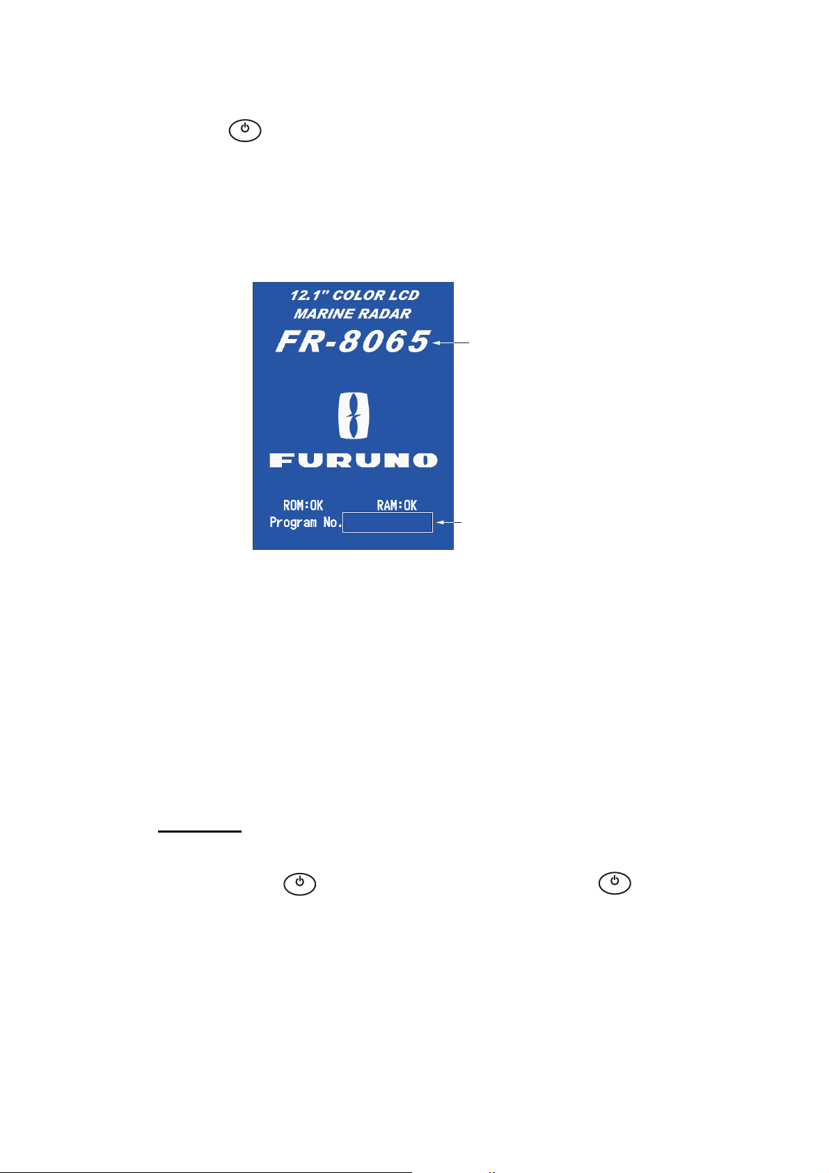
Press the key to turn on the radar.To turn off the radar, press and hold the key
until the screen turns off.
When you turn on the power, the initialization screen appears followed by the start-up
screen. The start-up screen shows the model name, program number and the results
of the ROM and RAM check, "OK" or "NG" (No Good). If "NG" appears, contact your
dealer for instruction.
L
Model name
appears here.
0359307-XX.XX
Program &
version no.
Start-up screen
After the self-tests have completed, the bearing scale and a digital timer appear. The
digital timer counts down the time necessary to warm the magnetron, which transmits
the radar pulses. The time to warm the magnetron is 90 seconds for FR-8045/FR8065 and FR-8125 radars, 180 seconds for FR-8255 radar.
After the timer reads 0:00, the STBY screen appears. The STBY screen has three
types. (See paragraph 1.44.2.) The radar is ready to transmit the radar pulses. Press
the STBY/TX key to transmit the radar pulses.
The STBY/TX key switches between standby and transmit. The antenna rotates in
transmit and is stopped in standby. The magnetron gets old with use. To increase the
life of the magnetron, set the radar in standby when you do not use the radar.
Quick start
If the magnetron is still warm, you can get the radar to TRANSMIT without the warm
B
L
R
I
up time. When the key is turned off by accident, turn on the key within 10
L
B
L
R
I
L
seconds after you turn off the power.
1-2
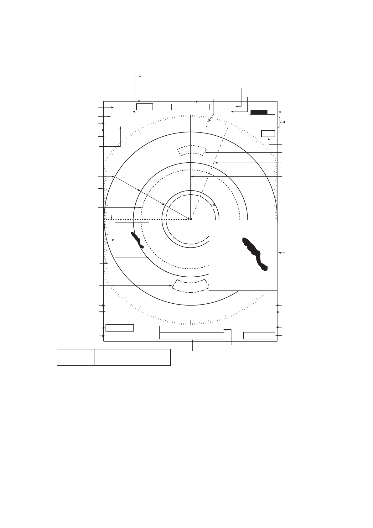
1.3 Display Indications
1.5
NM
Offcenter
(M: Manual, A: Auto, C: Custom)
Input source
(shown when display
unit functions as
remote display)
Range
Range ring interval
Pulselength
Display mode
Zoom indication
Custom setting
(1 - 3)
1.5
0.5
SP CS 1
H UP
ZOOM(R)
SLAVE
NM
OFFCENT(A)
HDG
350.0°
Heading
North marker
TRAIL(T)
15 S
Trail reference
Trail time
TUNEAUTO
ALM1_ACK
ALM2_OUT
WTC
1. OPERATION
Tuning indicator
Target Alarm 1 (2)
indications
WATCHMAN
Target alarm zone 1
No. 2 EBL
Range ring
Bearing scale
No. 1 VRM
No. 1 EBL
Zoom cursor
Cursor
+
Target alarm zone 2
Echo stretch
Echo averaging
ES 1
EAV 1
EBL
No. 1 EBL bearing
No. 2 EBL bearing
OWN SHIP
LAT 34°56.123N
LON 135°34.567E
SPEED 12.3KN
Nav data: Appears at screen bottom when [Data Box]
in the [Display] menu is set to [Nav] or [All]. Appropriate
sensors required to display nav data.
270.0°R
22.0°R
+ CURSOR
LAT 34°56.123N
LON 135°34.567E
TTG 01:00
241.0°R
+
WAYPOINT
B RG
RNG 0.876NM
TT G
14 .8 °
00:20
VECT
TRUE 05:00
1.592
NM
0.889
0.422
Vector time
Cursor data
(Range and bearing or L/L position)
IR 1
A/C AUTO
VRM
NM
NM
Heading line
No. 2 VRM
Zoom window
Interference rejector
Auto adjustment of
rain and sea clutters
No. 1 VRM range
No. 2 VRM range
Display indications
1-3
1. OPERATION
1.4 How to Adjust Display Brilliance, Panel Dimmer
You can adjust the display brilliance and panel dimmer as follows:
B
L
R
I
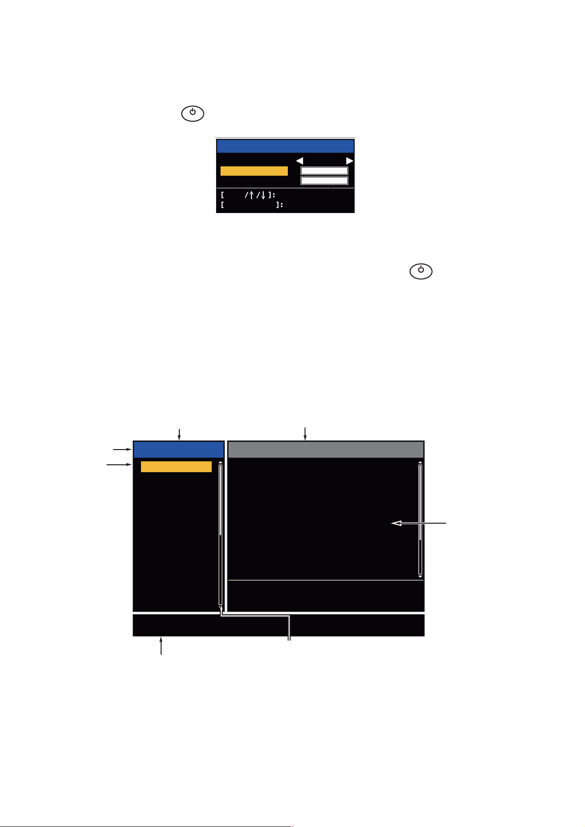
1. Press the key to show the [Brill/Panel] dialog box.
2. Press the [ENTER] key (or S, T) to select [Brill] or [Panel].
3. Use W or X to adjust. (For brilliance you can also use the key.)
4. Press the CANCEL/HL OFF key to close the window.
L
Brill
Panel
Enter
CANCEL/HL OFF
Brill/Panel
Max
(1~16)
(1~ 8)
Min
16
8
Select
Close
Brill/Panel dialog box
B
L
R
I
L
1.5 Menu Description
This FR-8045/FR-8065/FR-8125/FR-8255 series has 15 menus and 6 sub menus.
Below is the basic procedure for menu operation.
1. Press the MENU key to open the menu.
Menu
Title bar*
Cursor*
Menu
Brill/Color
Display
Echo
Custom 1
Custom 2
Custom 3
Alarm
Target Trails
Tuning
Others
Target
Echo Brill
Rings Brill
Mark Brill
HL Brill
Character Brill
Echo Shading
Display Color
Echo Color
Background Color
[ENTER]: Enter
[MENU] Exit
Currently selected menu
Brill/Color
: 8
: 4
: 4
: 4
: 4
: 1
: Custom
: Yellow
: Black
[CANCEL/HL OFF]: Back
Menu items
and current
settings
1-4
Adjusting brilliance and color
Scroll bar (Indicates menus currently not shown in menu
Guide message
(The simple explanation for
the current menu.)
window. Black vertical line indicates location in menu.
You can see the menus and sub menus currently not shown
by using or .)
*: Title bar in currently controlled column is blue; cursor selection is yellow.
Title bar of inactive column is gray.
Menu
1. OPERATION
2. Use S or T to select a menu or sub-menu.The cursor (yellow) in the [Menu] col-
umn indicates the menu currently selected. The menu items in the right-hand window change according to the menu selected.
Menu Description
[Brill/Color]: Adjust the brilliance and color.
[Display]: Set up the display features.
[Echo]: Adjust the radar echo.
[Custom 1] - [Custom 3]: Adjust the user settings.
[Alarm]: Set up the alarm features.
[Target Trails]: Process the trails of radar targets.
[Tuning]: Adjust the radar tuning.
[Others]: Set up other items.
[Target]: Set up the targets configuration.
[ARPA]: Set up the ARPA targets.
[AIS]: Set up the AIS targets.
[GPS]: Set up the GP-320B (Black-Box GPS).
[System]
[Initial]: Initial Setting.
[Tests]: Diagnostic self test, LCD test and ARPA test. See section 6.7 to 6.9.
[Sector Blanks]: Set sector blanks to prevent the transmission in a certain area.
[Units]: Set up units.
[Installation] and [Factory]: For use by the installer. See Installation Manual.
3. Press the ENTER key to switch the cursor to the menu items column. The cursor
in the menu column now turns gray and the cursor in the menu items column is
yellow. The control moves to the menu items column.
To switch the cursor from the menu items column to the menu column, use the
CANCEL/HL OFF key. The color of the title bar of the active column is blue and
of the inactive column in gray.
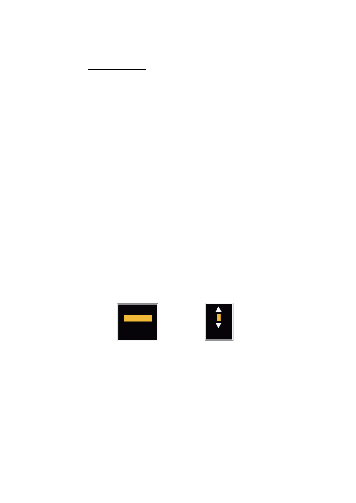
4. Use S or T to select a menu item and press the ENTER key. A window with options for the related menu item appears.
Day
Night
Twilight
Custom
Display Color options Echo Brill setting window
8
(1~8)
Example windows
5. Use S or T to select an option or numeric value.
6. Press the ENTER key to save your selection. To close the window without saving,
press the CANCEL/HL OFF key.
7. Press the MENU key to close the menu.
Note: The menus on the [IEC] and [Russian-River] types close automatically when
there is no menu operation for 10 seconds, according to IEC regulations. The following
menus and screens are excluded from this regulation:
[Alarm message], [Alarm status], [Tuning Init Adjust], [GPS self test], [GPS satellite
monitor], [System self test], [System LCD pattern], and [Auto installation setup]. The
menus do not close automatically in the [River] or [Sea] configuration.
1-5
1. OPERATION
1.6 Tuning
In default, the radar receiver can be tuned automatically after you set the radar to TX.
If you require fine tuning in manual, do the following:
1. Transmit the radar and select the maximum range with the RANGE key.
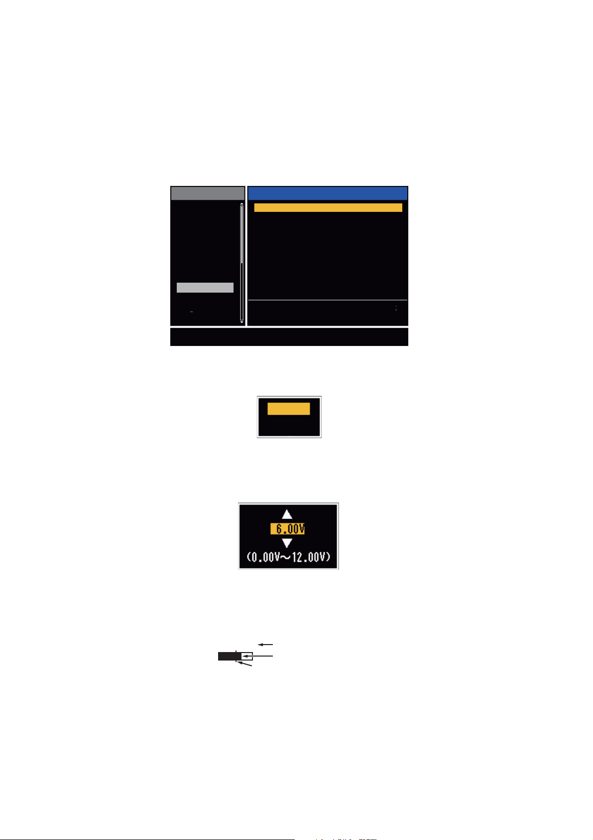
2. Press the MENU key to open the menu.
3. Use S or T to select [Tuning] and press the ENTER key.
Menu
Brill/Color
Display
Echo
Custom 1
Custom 2
Custom 3
Alarm
Target Trails
Tuning
Others
Target
Choosing a tuning mode
[ENTER]: Enter
[MENU] Exit
Tuning Mode
Manual Tuning
Tuning Init Adjust
Tuning
: Auto
: 6.00V
[CANCEL/HL OFF]: Back
Tuning menu
4. Use S or T to select [Tuning Mode] and press the ENTER key.
Auto
Manual
Tuning Mode options
5. Use S or T to select [Manual] and press the ENTER key.
6. Use S or T to select [Manual Tuning] and press the ENTER key.
Manual Tuning setting window
7. Use S or T to adjust the tuning while you look at the tuning bar in the upper-right
corner of the display. The best tuning point is where the tuning bar moves to a
maximum value. The vertical bar on the tuning bar shows the tuning voltage.
TUNE MAN
Tuning method (Manual)
Tuning bar
Vertical bar
8. Press the ENTER key.
9. Press the MENU key to close the menu.
Note: If the automatic tuning does not give the correct tuning, run the [Tuning Init Adjust] again.
1-6
1.7 Display Modes
This radar has the display modes shown below. All modes except head up require a
heading signal. The true motion mode additionally requires position data.
Relative Motion (RM)
• [Head Up] (H UP)
• [Course Up] (C UP)
• [North Up] (N UP)
• [True View] (TRUE VIEW)
True Motion
• [True Motion] (TM)
1.7.1 How to select the display mode
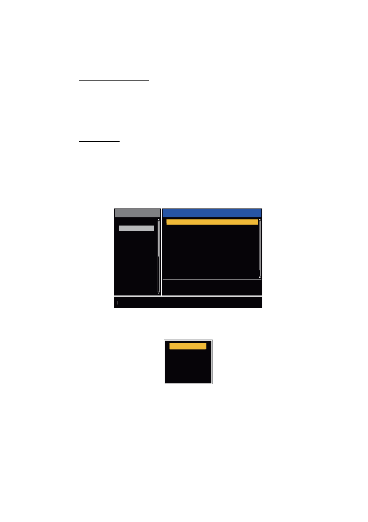
1. Press the MENU key to open the menu.
2. Use S or T to select [Display] and press the ENTER key.
1. OPERATION
Menu
Brill/Color
Display
Echo
Custom 1
Custom 2
Custom 3
Alarm
Target Trails
Tuning
Others
Target
Choosing the presentation mode
Display Mode
Zoom
Zoom Mode
Offcenter Mode
Save Offcenter
Echo Area
Base Text Display
Data Box
Gain/Sea/Rain Bar
[ENTER]: Enter
[MENU] Exit
Display
: Head Up
: Off
: Relative
: Normal
: All
[CANCEL/HL OFF]: Back
Display menu
3. Use S or T to select [Display Mode] and press the ENTER key.
Head Up
Course Up
North Up
True Motion
True View
4. Use S or T to select a display mode and press the ENTER key.
5. Press the MENU key to close the menu.
Note: All modes except head up require a heading signal in AD-10 format or NMEA
format. If the heading signal is lost, the mode is changed to head up and the north
marker disappears. The display for heading is XXX.X and the alarm sounds. The message "GYRO" (AD-10 format data) or "NMEA_HDG" (NMEA format data) appears in
the alarm message display. To stop the audio alarm, press any key. When the heading
signal is restored, check the heading. To check the heading, press the F3 key. When
the heading signal is restored, the current heading is displayed at the heading indication.
1-7
1. OPERATION
1.7.2 Description of display modes
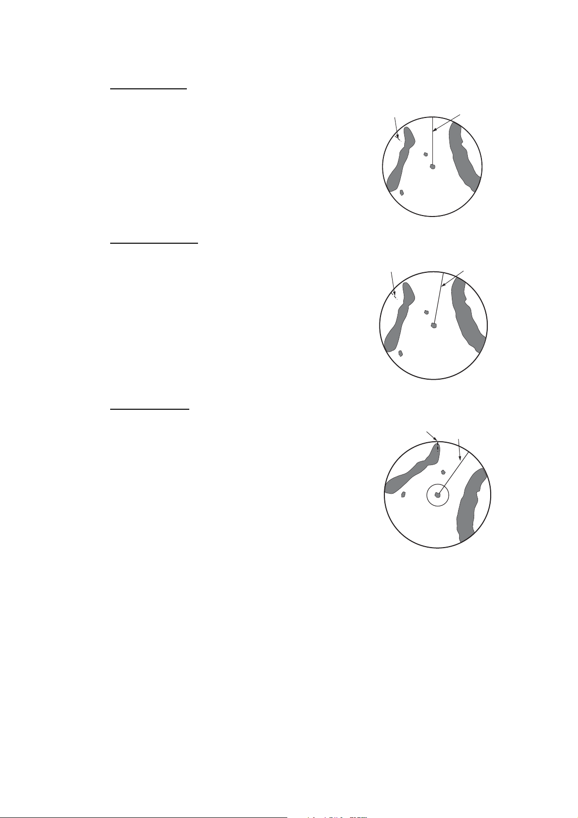
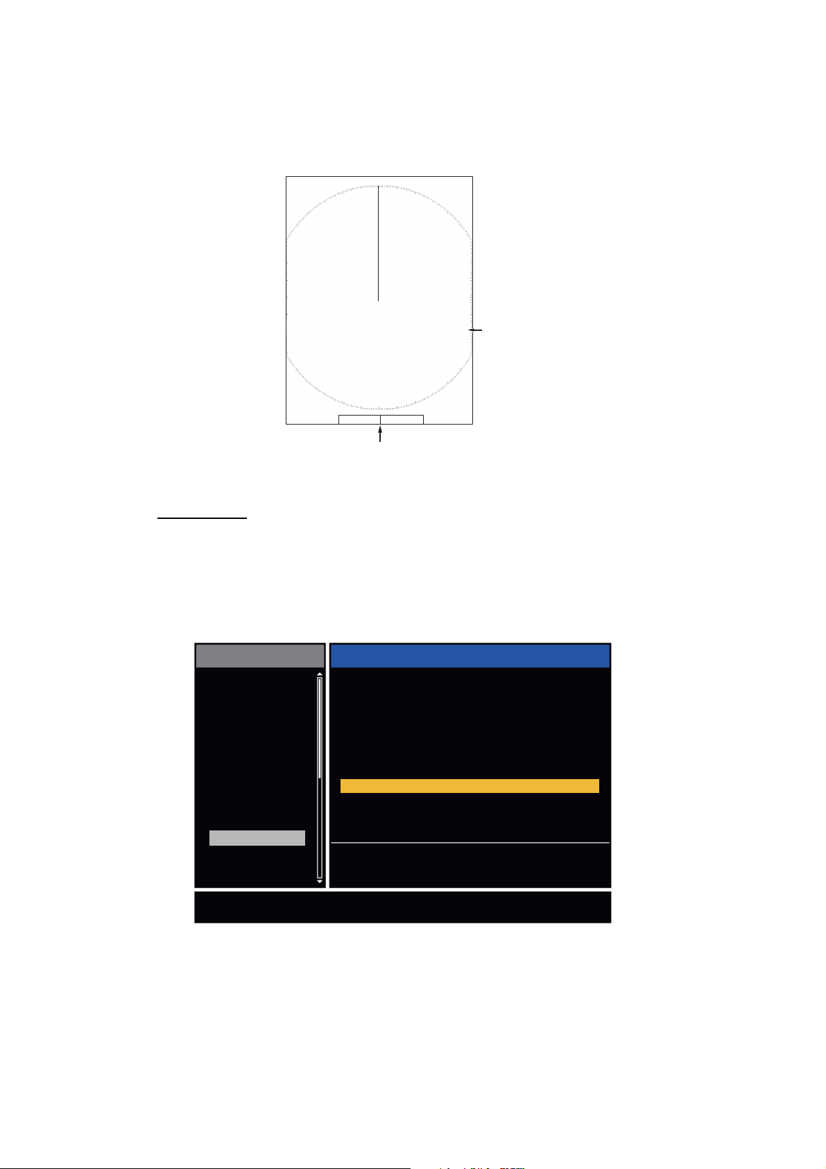
Head up mode
A display without azimuth stabilization in which the line
that connects the center with the top of the display indicates your heading. Targets are shown at their measured distances and their directions relative to your
heading. The short dotted line on the bearing scale is
the north marker.
Course up mode
The radar picture is stabilized and displayed with the
currently selected course at the top of the screen.
When you change the heading, the heading line
moves with the course selected. If you select a new
course, select the course up mode again to display
the new course at the top of the display. Targets are
shown at their measured distances and their directions relative to the set course, which is at the 0-degree position. The heading line moves according to
the yawing and any course change.
North marker
North marker
Heading line
Heading line
North up mode
Targets are shown at their measured distances and
their true (compass) directions from your ship. North is
at the top of the screen. The heading line changes its
direction according to your heading.
North marker
Heading line
1-8
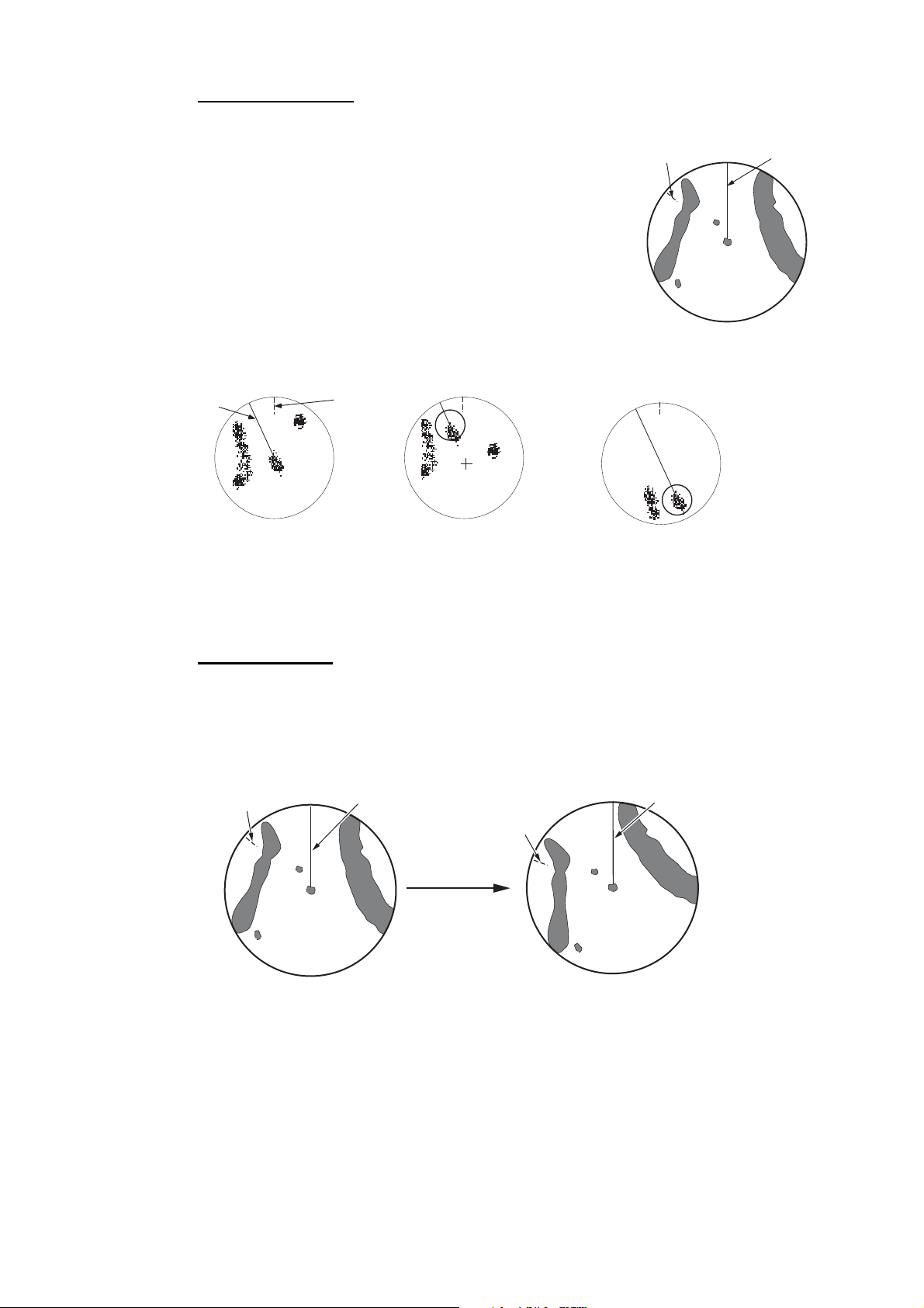
True motion mode
n
Your ship and other objects in motion move with their true
courses and speed. All fixed targets, like landmasses, appear as fixed echoes in ground stabilized TM. When your
ship reaches a point that is 75% of the radius of the display, the position is reset. The ship appears at 75% radius
opposite to the extension of the heading line on the display center. You can manually reset your ship symbol if
you press the OFF CENTER key.
North marker
1. OPERATION
Heading li
Heading
line
(a) True motion
is selected
North
marker
(b) Your ship has reached a
point 75% of display radius
(c) Your ship is automatically
reset to 75% of display radius
Example: Automatic reset of your ship marker in true motion mode
True view mode
The echoes move in real time according to the change of the heading of your ship. The
heading line is at the top of the screen. When the heading signal is lost, this function
is not available and the display mode automatically changes to the head up mode. The
[Wiper] is not available in this mode (see section 1.31).
North marker
Heading line
North marker
Heading line
The echoes move
according to the
change of the heading
of your ship during
one sweep.
1-9
1. OPERATION
1.8 How to Select a Range Scale
The selected range scale, range ring interval and pulselength are shown at the upper
left corner on the screen. When an object target comes closer, reduce the range scale
so that the target appears in 50-90% of the display radius.
Use the RANGE key to select range. Press the "+" part of the key to raise the range;
the "-" part to lower the range.
1.9 How to Adjust the Gain (sensitivity)
The gain functions to adjust the sensitivity of the receiver for the best reception. The
gain is adjusted automatically or manually.
1. Press the MENU key to open the menu.
2. Use S or T and select [Echo] and press the ENTER key.
3. Use S or T to select [Gain Mode] and press the ENTER key.
4. Use S or T to select [Auto] or [Manual] and press the ENTER key.
the window for Gain/Sea/Rain indicator shown below appears. This
window closes automatically in the [River] or [Sea] mode when there
is no menu operation for ten seconds. [Auto] is for adjusting the gain automatically. For [Manual] go to "Manual mode" below.
Auto
Manual
AUTO: Auto, MAN: Manual
Gain/Sea/Rain
GAIN MAN
SEA
MAN
RAIN
MAN
[CANCEL/HL OFF: Close
Gain setting bar
Gain/Sea/Rain indicator
5. Press the CANCEL/HL OFF key to close the window.
6. Press the MENU key to close the menu.
Note: To adjust the gain finely in [Auto] mode, rotate the GAIN knob. The confirmation
message appears. If you select [Yes] the mode changes to [Manual] mode. Rotate the
Gain knob to adjust the gain.
Are you sure to change to manual mode?
Manual mode
1-10
1. Rotate the GAIN knob to adjust the gain so that weak noise appears on all of the
screen. If the gain is too low, weak echoes are erased. If the gain is too high, the
background noise hides weak targets.
2. Press the CANCEL/HL OFF key to close the window.

1.10 How to Reduce the Sea Clutter
The reflected echoes from the waves appear around your ship and have the name
"sea clutter". The sea clutter extends according to the height of waves and antenna
above the water. When the sea clutter hides the targets, use the A/C SEA control to
reduce the clutter, either manually or automatically.
Auto mode
1. Press the Menu key to open the menu.
2. Use S or T to select [Echo] and press the ENTER key.
3. Use S or T to select [Sea Mode] and press the ENTER key.
4. Use S or T to select [Auto] or [Manual] and press the ENTER key. The window
for Gain/Sea/Rain indicator appears. (Refer to the illustration of step 4 in
section 1.9). If you selected [Auto], go to step 5. For [Manual], go to "Manual
mode" below.
5. Press the CANCEL/HL OFF key to close the window. [Auto] is used to reduce the
sea clutter automatically. If the sea clutter is strong while cruising along a coastline in the [Auto] mode, go to step 6. If not, go to step 9.
1. OPERATION
6. Use S or T to select [Auto Sea] and press the ENTER key.
Coastal
Advanced
7. Use S or T to select [Coastal] or [Advanced] then press the ENTER key. The window for Gain/Sea/Rain indicator appears for confirmation.
[Coastal]: Suppress both land and sea clutter. For cruising along a coastline.
[Advanced]: Automatically identify land echoes from sea reflections to suppress
only sea reflections. Use this mode for general use.
8. Press the CANCEL/HL OFF key to close the menu.
9. Press the MENU key to close the menu,
Note: When you want to adjust the sea clutter finely in [Auto] mode, rotate the
A/C SEA knob. The confirmation window appears. If you select [Yes], the mode
changes to [Manual] mode. Rotate the A/C SEA knob to adjust the sea clutter.
Are you sure to change to manual mode?
Confirmation message
Manual mode
1) Rotate the A/C SEA knob to reduce the sea clutter.
Note: When the setting of the A/C SEA control is correct, the clutter is broken into
small dots, and small targets become identified. If the setting is not enough, targets
are hidden in the clutter. If the setting is higher than necessary, both sea clutter
and targets disappear from the display. Normally adjust the control until the clutter
has disappeared to leeward, but a small amount of the clutter is visible windward.
1-11

1. OPERATION
2) Press the CANCEL/HL OFF key to close the window.
Sea clutter at
screen center
A/C SEA control adjusted;
sea clutter reduced
1.11 How to Reduce the Rain Clutter
The reflections from the rain or snow appear on the screen. These reflections have the
name "rain clutter". When the rain clutter is strong, targets in the rain clutter are hidden
in the clutter. Reflections from the rain clutter are easily identified from true targets by
their wool-like appearance.The A/C RAIN control, like the A/C SEA control, adjusts
the receiver sensitivity, but in longer range. If the setting is high, the rain clutter is more
reduced. The rain control breaks the continuous display of rain or snow reflections into
a random pattern. When the rain clutter hides the targets, adjust the rain control (automatic or manual) to reduce the clutter.
Auto mode
1. Press the MENU key to open the menu.
2. Use S or T to select [Echo] and press the ENTER key.
3. Use S or T to select [Rain Mode] and press the ENTER key.
4. Use S or T to select [Auto] or [Manual] then press the ENTER key. The window
for Gain/Sea/Rain indicator appears (refer to the illustration of step 4 at
section 1.9). If you selected [Auto], go to step 5. For [Manual], go to "Manual
mode" below.
5. Press the CANCEL/HL OFF key to close the window.
6. Use S or T to select [Auto Rain] and press the ENTER key.
Calm
Moderate
Rough
7. Use S or T to select [Calm], [Moderate] or [Rough] then press the ENTER key.
The window for Gain/Sea/Rain indicator appears for confirmation.
[Calm]: For light rain
[Moderate]: When you cannot reduce the rain clutter with [Calm] mode
[Rough]: For heavy rain
8. Press the CANCEL/HL OFF key to close the window.
9. Press the MENU key to close the menu.
Note: When you want to adjust the rain clutter finely in [Auto] mode, rotate the A/C
RAIN knob. The confirmation message appears. If you select [Yes], the mode chang-
es to [Manual] mode. Rotate the A/C RAIN knob to adjust the rain clutter.
1-12
Manual mode
1. Rotate the A/C RAIN knob to reduce the rain clutter.
2. Press the CANCEL/HL OFF key to close the window.
1. OPERATION
Rain clutter at
screen center
A/C RAIN control adjusted;
rain clutter reduced
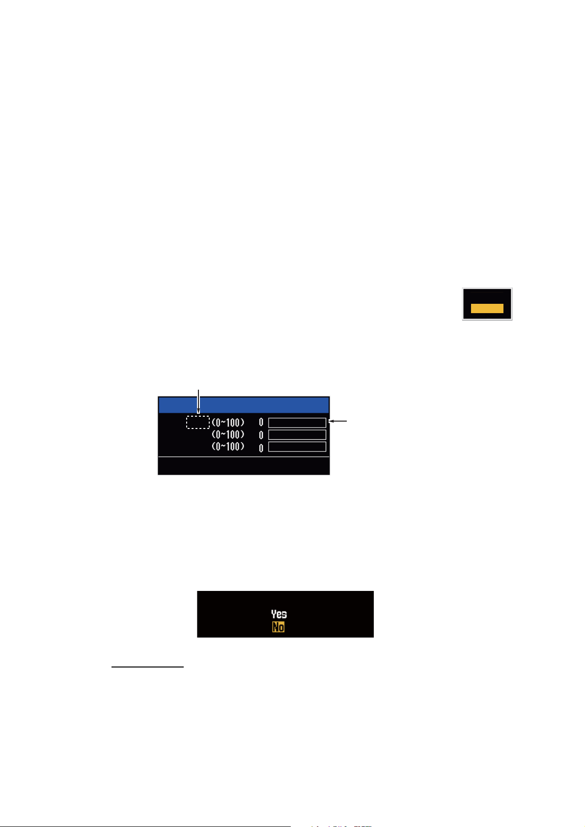
1.12 Automatic Adjustments of Sea and Rain Clutters
When you can not correctly reduce the sea clutter or rain clutter with the related control, turn on the automatic anti-clutter feature. When this feature is turned on,
"A/C AUTO" appears at the lower-right corner.
1. Press the MENU key to open the menu.
2. Use S or T to select [Echo] and press the ENTER key.
3. Use S or T to select [A/C Auto] and press the ENTER key.
4. Use S or T to select [Off] or [On] then press the ENTER key.
5. Press the MENU key to close the menu.
Caution on use
• Echoes that cover wide areas (like land and islands) can become smaller when the
[A/C Auto] is used.
• When [A/C Auto] is active, the strength of a target in sea clutter or rain clutter can
be lower than actual strength. In this case change to manual A/C SEA and manual
A/C RAIN and adjust the picture.
A/C Auto: Off
:£:¸:Å:»
Land
Target
A/C Auto: On
:£:¸:Å:»
1-13
1. OPERATION
1.13 Cursor
The cursor functions to find the range and bearing (default function) to a target or the
latitude and longitude position of a target. Use the CursorPad to move the cursor into
position and read the cursor data at the screen bottom.
0.5
NM
+
Cursor
110.1
° R 0.488
+
NM
Cursor data
(range and bearing,
or latitutde and longitude)
Cursor data
You can show the cursor data as range and bearing (from your ship to the cursor) or
latitude and longitude. Position and heading signal are required.
1. Press the MENU key to open the menu.
2. Use S or T to select [Others] and press the ENTER key.
Menu
Brill/Color
Display
Echo
Custom 1
Custom 2
Custom 3
Alarm
Target Trails
Tuning
Others
Target
F1 Setup
F2 Setup
F3 Setup
WPT Mark
EBL Reference
VRM Unit
Cursor Position : Rng/Brg
TLL Key Mode
[ENTER]: Enter
[MENU] Exit
Others
: Gain Mode
: Sea Mode
: A/C Auto
: Off
: Relative
: NM
: TLL Output
[CANCEL/HL OFF]: Back
1-14
Choosing display mode of cursor position
Others menu
3. Use S or T to select [Cursor Position] and press the ENTER key.
Rng/ Brg
Lat/Lon
Cursor Position options
4. Use S or T to select [Rng/Brg] (Range/Bearing) or [Lat/Lon] (Latitude/Longitude)
then press the ENTER key. (When the navigation data box display is set to [Nav]
or [All] in the [Display] menu, cursor latitude and longitude position cannot be displayed in the cursor data box.)
5. Press the MENU key to close the menu.
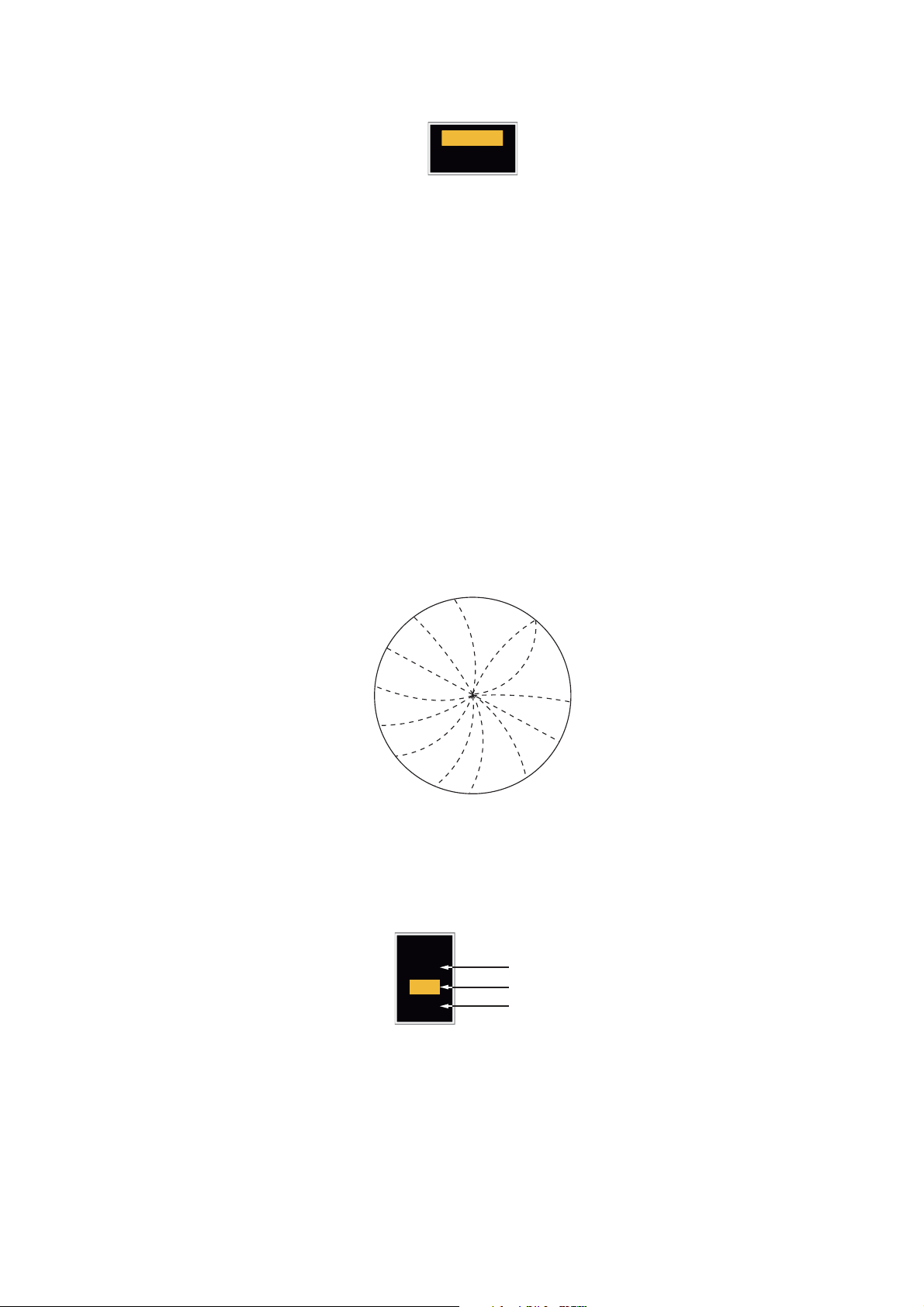
1.14 Interference Rejector
The radar interference can occur when your ship is near the radar of another ship that
operates on the same frequency band with your radar. The interference shows on the
screen as many bright dots. The dots can be random or in the shape of dotted lines
that run from the center to the edge of the display. You can identify the interference
from the normal echoes, because the interference does not appear in the same location at the next antenna rotation. When this feature is turned on, "IR 1", "IR 2" or "IR
3" appears at the lower-right corner.
1. OPERATION
Interference
1. Press the MENU key to open the menu.
2. Use S or T to select [Echo] and press the ENTER key.
3. Use S or T to select [Int Rejector] and press the ENTER key.
Off
1
2
3
Indication at the lower-right corner of the display
4. Use S or T to select [Off], [1], [2] or [3] then press the ENTER key. [3] removes
the interference the most.
5. Press the MENU key to close the menu.
Note: When there is no interference, turn off the interference rejector so you do not
miss the small targets.
IR 1
IR 2
IR 3
1-15
1. OPERATION
1.15 How to Measure the Range to a Target
You can measure the range to a target in three methods. You can use the fixed range
rings, the cursor (if set to measure range and bearing) and the VRM (Variable Range
Marker).
Use the fixed range rings to get a rough estimate of the range to a target. The fixed
range rings are the concentric solid circles about your ship. The number of rings
changes with the selected range scale. The interval of the range ring is displayed at
the upper-left corner of the screen. Count the number of rings between the center of
the display and the target. Check the range ring interval and measure the distance of
the echo from the nearest ring.
1.15.1 How to adjust range ring brilliance
1. Press the MENU key to open the menu.
2. Use S or T to select [Brill/Color] and press the ENTER key.
3. Use S or T to select [Rings Brill] and press the ENTER key.
Menu
Brill/Color
Display
Echo
Custom 1
Custom 2
Custom 3
Alarm
Target Trails
Tuning
Others
Target
Adjusting range ring brilliance
4. Use S or T to select an option and press the ENTER key. [4] is the brightest. [Off]
turns off the range rings.
Echo Brill
Rings Brill
Mark Brill
HL Brill
Character Brill
Echo Shading
Display Color
Echo Color
Background Color
[ENTER]: Enter
[MENU] Exit
Brill/Color menu
Brill/Color
: 8
: 4
: 4
: 4
: 4
: 1
: Custom
: Yellow
: Black
[CANCEL/HL OFF]: Back
Off
1
2
3
4
1-16
Rings/Brill options
5. Press the MENU key to close the menu.

1.15.2 How to measure the range with a VRM
There are two VRMs, No. 1 and No. 2. The VRMs are dashed rings so that you can
identify the rings from the fixed range rings. You can identify VRM 1 from VRM 2 by
different lengths of dashes. The dashes of the No. 1 VRM are shorter than those of
the No. 2 VRM.
1. Press the VRM key to display either of the VRMs. Press the VRM key to change
the active VRM between No. 1 and No. 2. The indication of the currently active
VRM is in a rectangle.
2. Use the CursorPad to align the Variable Range Marker with the inner edge of the
target. Read the distance at the lower-right corner of the screen. Each VRM remains at the same geographical distance when you operate the RANGE key. The
size of the VRM ring changes in proportion to the selected range scale.
3. Press the ENTER key to anchor the VRM.
4. To erase a VRM, press the VRM key to activate the VRM and press the CANCEL/
HL OFF key.
1. OPERATION
VRM 1
VECT
37.4
º R
TRUE 05:00
5.044
+
Cursor range and bearing
1.15.3 How to select VRM unit
You can select the unit of measurement used by the VRM. The selections are nautical
miles (NM), kilometers (KM), statute miles (SM), kiloyard (KYD) or nautical miles and
yards (NM&YD). The cursor range unit is also changed when the VRM unit is
changed.
1. Press the MENU key to open the menu.
+
NM
Target
Cursor (+)
VRM 2
The currently active VRM
is in a rectangle.
VRM
5.044NM
2.082NM
VRM 1 range
VRM 2 range
2. Use S or T to select [Others] and press the ENTER key.
1-17

1. OPERATION
3. Use S or T to select [VRM Unit] and press the ENTER key.
NM
KM
SM
KYD
NM&YD
NM: 0.1 NM or above
YD: Less than 0.1 NM
4. Use S or T to select the unit and press the ENTER key.
5. Press the MENU key to close the menu.
1.16 How to Measure the Bearing to a Target
Use the Electronic Bearing Line (EBL) to take a bearing of a target. There are two
EBLs, No. 1 and No. 2. Each EBL is a straight dashed line from the center of the
screen to the edge. The dashes of the No. 1 EBL are shorter than those of the No. 2
EBL.
1.16.1 How to measure the bearing with an EBL
1. Press the EBL key to display either of the EBLs. Press the EBL key to change the
active EBL between No. 1 and No. 2. The indication of the currently active EBL is
in a rectangle.
2. Use the CursorPad to put the EBL on the center of the target. Read the bearing
at the lower-left corner of the screen.
3. Press the ENTER key to anchor the EBL.
4. To erase an EBL, press the EBL key to activate the EBL and press the CANCEL/
HL OFF key.
+
EBL 1
Target
Cursor (+)
EBL 2
1-18
The currently active EBL
is in a rectangle.
EBL 1 bearing
EBL 2 bearing
How to measure the bearing with the EBL
EBL
270.0
°
R
VECT
45.0
+
°
R
45.0
°
TRUE 05:00
R
5.044 NM
Cursor range and bearing

1. OPERATION
1.16.2 EBL reference
"R" (relative) follows the EBL indication if the bearing is relative to the heading of your
ship. "T" (true) follows the EBL indication if the bearing is in reference to the north. You
can select relative or true in the head up and true view modes. The bearing indication
is true in all other modes. True bearing requires a heading sensor.
1. Press the MENU key to open the menu.
2. Use S or T to select [Others] and press the ENTER key.
3. Use S or T to select [EBL Reference] and press the ENTER key.
Relative
True
4. Use S or T to select [Relative] or [True] then press the ENTER key.
5. Press the MENU key to close the menu.
1.17 How to Measure the Range and Bearing Between Two Targets
You can move the origin of the EBL to measure the range and bearing between two
targets.
1. Press the EBL key to select the bearing indication of EBL 1 or EBL 2. The indica-
tion of the currently active EBL is in a rectangle.
2. Use the CursorPad to put the cursor on the center of the target A.
3. Press the OFF CENTER key to move the origin of the EBL to the location selected
at step 2.
4. Use the CursorPad to put the cursor on the center of the target B.
5. Press the VRM key to display the VRM having the same number as the EBL acti-
vated at step 1. The indication of the currently active VRM is in a rectangle.
6. Use the CursorPad to set the VRM on the inner edge of the target B.
7. Read the bearing and range indica-
tions at the bottom of the screen.
Note: When you press the OFF CEN-
TER key in EBL operation, the origin of
an EBL moves between the screen center and cursor location. To return the origin of an EBL to the screen center, press
the ENTER key when the origin of an
EBL is on the screen center.
VRM 1
EBL 1
Target B
+
Target A
EBL origin
Target C
EBL 2
Target D
+
VRM 2
EBL
45.0
°
R
°
R
327.0
Range/bearing between
targets A and B
VRM
0.550NM
0.550NM
Range/bearing between
targets C and D
1-19

1. OPERATION
1.18 How to Select a Pulselength
The pulselength in use appears at the upper-left position on the screen. The pulselengths are set to each range scale and custom setup. You can change the pulselength on the 1.5 nm, 1.6 nm, 3 nm or 3.2 nm range with the following procedure.
Pulselength cannot be changed on other ranges. (You can change the pulselength on
the 2 nm or 4 nm range in the [Russian-River] mode.) Use a longer pulse when your
purpose is long range detection. Use a shorter pulse when the resolution is important.
Note: Press the CUSTOM key several times to activate the [Echo] menu until the [CS
1] (2, 3) indication (custom setting) disappears from the screen. See the illustration in
section 1.3.
1. Press the MENU key to open the menu.
2. Use S or T to select [Echo] and press the ENTER key.
Menu
Brill/Color
Display
Echo
Custom 1
Custom 2
Custom 3
Alarm
Target Trails
Tuning
Others
Target
Choosing a pulse length
Sea Mode
Auto Sea
Rain Mode
Auto Rain
A/C Auto
Pulse Length
Echo Stretch
Echo Average
Noise Rejector
[ENTER]: Enter
[MENU]: Exit
Echo
: Manual
: Advanced
: Manual
: Moderate
: Off
: Short
: Off
: Off
: Off
[CANCEL/HL OFF]: Back
Echo menu
3. Use S or T to select [Pulse Length] and press the ENTER key
Short
Long
1-20
Pulse Length options
4. Use S or T to select [Short] or [Long] then press the ENTER key. The pulse-
length indication at the upper-left corner changes according to your selection as
shown below.
1.5 nm or 1.6 nm (or 2 nm in the [Russian-River] mode): "SP" for [Short] pulse,
"MP" for [Long] pulse
3 nm or 3.2 nm (or 4 nm in the [Russian-River] mode): "MP" for [Short] pulse, "LP"
for [Long] pulse
5. Press the MENU key to close the menu.

1.19 Target Alarm
CAUTION
The target alarm looks for targets (ship, landmass, etc.) in the area you set. When a
target enters or exits the alarm area, audiovisual alarms are released.
CAUTION
·
Do not depend on the alarm as the only
means to detect possible collision
situations.
·
Adjust the A/C SEA, A/C RAIN and GAIN
controls correctly so that the alarm
system does not miss the target echoes.
1.19.1 How to set a target alarm zone
The following procedure shows you how to set a target alarm zone.
1. OPERATION
1. Press the TARGET ALARM key to activate ALARM 1 or ALARM 2. Press the
TARGET ALARM key to change the active ALARM between No. 1 and No. 2. The
indication of the currently active ALARM is in a rectangle at the upper-right corner
of the screen.
2. Use the CursorPad to move the cursor to the position A and press the ENTER
key.
3. Move the cursor to the position B and press the ENTER key. The rectangle that
shows alarm status indication at the upper-right corner of the screen disappears.
(See figure below)
Target alarm zone 1
(Length of dash
and interval for
alarm zone 2 are
longer than alarm
zone 1.)
ALM1_IN
ALM2_OUT
A
B
+
Alarm status
Cursor
Note 1: To set a 360-degree guard zone, set the position B in the same bearing as the
position A.
Note 2: When the target alarm zone is not within the range in use, the indication"ALM1(or 2)_RNG" replaces "ALM1(or 2)_IN(or OUT)" in the alarm status area.
(When the target alarm zone is within the range of full off-centering, the indication
does not change.) Select a range which displays the target alarm zone.
1-21

1. OPERATION
1.19.2 How to stop the audio alarm
When a target enters (or exits) the target alarm zone, the target flashes and the alarm
sounds. The alarm message appears at the bottom of the screen. To stop the audio
alarm, press any key. When the target enters (or exits) the target alarm zone again,
the audio alarm sounds.
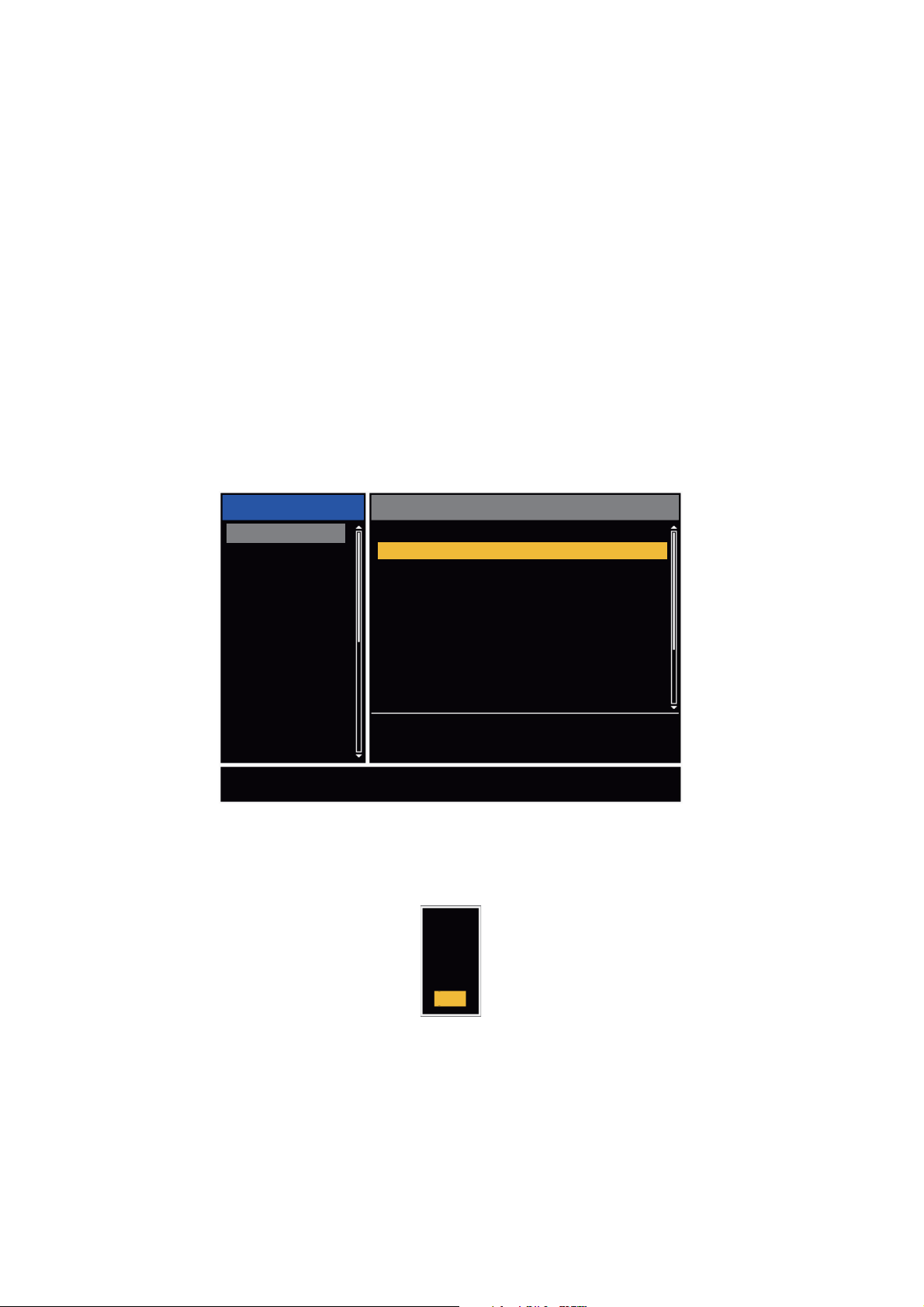
1.19.3 How to select the alarm type
You can set the target alarm to activate against targets which enter or exit the alarm
zone.
“In” target alarm
“Out” target alarm
In and Out target alarms
1. Press the MENU key to open the menu.
2. Use S or T to select [Alarm] and press the ENTER key.
Menu
Brill/Color
Display
Echo
Custom 1
Custom 2
Custom 3
Alarm
Target Trails
Tuning
Others
Target
Choosing the type (in/out) of target alarm 1
Target Alarm 1
Target Alarm 2
Alarm Level
Watchman
Panel Buzzer
External Buzzer
Alarm Status
[ENTER]: Enter
[MENU]: Exit
Echo
: In
: In
: Med
: Off
: On
: On
[CANCEL/HL OFF]: Back
Alarm menu
3. Use S or T to select [Target Alarm 1] or [Target Alarm 2] then press the ENTER
key.
1-22
In
Out
Target Alarm options
4. Use S or T to select [In] or [Out].
[In]: When the targets enter a target alarm zone, the alarm sounds.
[Out]: When the targets exit a target alarm zone, the alarm sounds.
5. Press the ENTER key followed by the MENU key.

1.19.4 How to sleep a target alarm temporarily
When you do not require a target alarm temporarily, you can sleep the target alarm.
The alarm zone remains on the screen, but, any targets that enter or exit the alarm
zone do not trigger the audio and visual alarms.
1. Press the TARGET ALARM key to select the ALARM 1 or ALARM 2 indication at
the upper-right corner on the screen. The selected indication is in a rectangle.
2. Press the CANCEL/HL OFF key. The alarm indication now shows "ALM1(or
2)_ACK".
To activate a sleeping target alarm zone, press the TARGET ALARM key to select the
ALARM 1 or ALARM 2 and press the ENTER key. The alarm indication then changes
to "ALM1(or 2)_IN(or OUT)".
1.19.5 How to deactivate a target alarm
1. Press the TARGET ALARM key to select the ALARM 1 or ALARM 2 indication at
the upper-right corner on the screen. The selected indication is in a rectangle.
2. Press the CANCEL/HL OFF key. The alarm indication now shows "ALM1(or
2)_ACK".
1. OPERATION
3. Press the TARGET ALARM key. The alarm indication "ALM1(or 2)_ACK" is
shown in a dashed-line rectangle.
4. Press the CANCEL/HL OFF key. The target alarm zone and the alarm indication
are erased from the screen.
1.19.6 How to select the target strength which triggers a target alarm
You can select the target strength which triggers the target alarm as follows:
1. Press the MENU key to open the menu.
2. Use S or T to select [Alarm] and press the ENTER key.
3. Use S or T to select [Alarm Level] and press the ENTER key.
4. Use S or T to select the echo strength level.
5. Press the ENTER key followed by the MENU key.
Low
Med
High
1.19.7 How to turn the buzzer on/off
You can turn on/off the panel buzzer or external buzzer for target alarms. The panel
buzzer is for this equipment. The external buzzer is for the optional buzzer, which is
connected to this equipment to give the target alarm at a remote location.
1. Press the MENU key to open the menu.
2. Use S or T to select [Alarm] and press the ENTER key.
3. Use S or T to select [Panel Buzzer] (or [External Buzzer] for optional
buzzer) and press the ENTER key.
4. Use the S or T to select [On] or [Off] then press the ENTER key.
5. Press the MENU key to close the menu.
Off
On
1-23

1. OPERATION
1.20 How to Off-center the Display
You can off-center your ship position to expand the view field without selecting a larger
range scale. The display can be off-centered manually, or automatically according to
speed of the ship.
Note: Off-centering is not available in the true motion mode and the 64 NM range
scale or higher.
1.20.1 How to select the off-center mode
1. Press the MENU key to open the menu.
2. Use S or T to select [Display] and press the ENTER key.
3. Use S or T to select [Offcenter Mode] and press the ENTER key.
Manual
Custom
Auto
EXIT? YES
4. Use S or T to select [Manual], [Custom] or [Auto] then press the ENTER key.
Press the ENTER key to change between on and off.
5. After setting all options, use the T to select [EXIT? YES] and press the ENTER
key.
6. Press the MENU key to close the menu.
On
Off
Off
Offcenter Mode options
1.20.2 Off-center the display
Press the OFF CENTER key to move your ship position. When you press the OFF
CENTER key continuously, the mode changes in the sequence of OFF → Manual →
Custom → Auto → OFF → Manual → ... (the options available depend on setting selected at step 4 in section 1.20.1). When off-centering is active, "OFFCENT(M)",
"OFFCENT(C)" or "OFFCENT(A)" appears at the upper-left corner on the display.
Manual (Indication: "OFFCENT(M)")
Press the ENTER key
to change between
on and off.
1-24
You can move your ship position to the current cursor position on all modes except
true motion, within 75% of the available display area.
1. Press the OFF CENTER key several times until the off-center indication disappears.
2. Put the cursor in the position to off-center the display.
3. Press the OFF CENTER key several times until the indication "OFFCENT(M)" appears.

1. OPERATION
Custom (Indication: "OFFCENT(C)")
You can move your ship position to the position which you pre-set. Follow the procedure shown below to register the cursor position.
1. Press the OFF CENTER key several times until the off-center indication disappears.
2. Put the cursor on the position where to off-center the display.
3. Press the OFF CENTER key several times until the indication "OFFCENT(M)" appears.
4. Press the MENU key to open the menu.
5. Use S or T to select [Display] and press the ENTER key.
6. Use S or T to select [Save Offcenter] and press the ENTER key. The message
"Complete" appears.
7. Press any key to close the message window.
8. Press the MENU key to close the menu.
To change the mode to custom, press the OFF CENTER key several times until the
indication "OFFCENT(C)" appears.
Auto (Indication: "OFFCENT(A)")
The amount of automatic move is calculated according to speed of the ship. The maximum amount is 75% of the range in use. The formula to calculate automatic shift is
shown below.
Speed of ship
Offcenter speed setting
X 0.75 = Amount of move (%)
If the offcenter speed setting is 15 knots and the speed of the ship is 10 knots, for example, the amount of move at the stern of your ship will be 50% of the available display
area.
How to select offcenter speed
1. Press the MENU key to open the menu.
2. Use S or T to select [Initial] sub menu in [System] menu and press the ENTER
key.
3. Use S or T to select [Offcenter Speed] and press the ENTER key.
15kn
(1kn~99kn)
Offcenter Speed setting window
4. Use S or T to select the speed to use and press the ENTER key.
5. Press the MENU key to close the menu.
1-25

1. OPERATION
1.21 Zoom
The zoom function expands the length and width of a selected target as much as twice
its normal size, in the zoom window. You select the target to zoom with the zoom cursor.
The ARPA and AIS symbols can be displayed in the zoom window, but are not
zoomed. You can process ARPA and AIS targets that are in the zoom window, in the
same method as on the normal radar display.
There are three types of zoom.
[Relative]: The zoom cursor is fixed to the range and bearing from your ship.
[True]: The zoom cursor is fixed to a set geographical position.
[Target]: The zoom cursor is fixed to the zoomed AIS ARPA target.
1.21.1 Zoom mode
You can select the zoom mode from [Relative], [True] or [Target].
1. Press the MENU key to open the menu.
2. Use S or T to select [Display] and press the ENTER key.
3. Use S or T to select [Zoom Mode] and press the ENTER key.
4. Use S or T to select [Relative], [True] or [Target] then press the ENTER key.
Note: True zoom mode requires a heading signal and position data. If either signal is lost, true zoom mode is cancelled.
5. Press the MENU key to close the menu.
1.21.2 How to zoom
Relative or True zoom mode
1. Use the CursorPad to put the cursor on the position required.
2. Press the MENU key to open the menu.
3. Use S or T to select [Display] and press the ENTER key.
Relative
True
Target
Zoom Mode options
1-26
4. Use S or T to select [Zoom] and press the ENTER key.
Off
On
Zoom options
5. Use S or T to select [On] and press the ENTER key. The ZOOM indication ap-
pears at the upper-left corner on the screen. The zoom window and the zoom cursor also appear (see the illustration on the next page). To quit the zoom, select
[Off] instead of [On] and press the ENTER key.
6. Press the MENU key to close the menu.

1. OPERATION
1.5
NM
1.5
NM
Target zoom mode
The zoom window can display the ARPA or AIS target, as shown below.
ARPA: The symbol is enlarged twice its normal size.
AIS: The symbol is shown inside a broken square. (The symbol is not enlarged.)
The zoom cursor moves with the ARPA or AIS target.
Note: If neither ARPA nor AIS target is selected, the message "NO TARGET." appears. Press any key to erase the message.
1. Press the MENU key to open the menu.
2. Use S or T to select [Display] and press the ENTER key.
3. Use S or T to select [Zoom] and press the ENTER key.
4. Use S or T to select [On] and press the ENTER key.
The ZOOM indication appears at the upper-left corner on the screen. The zoom
window and the zoom cursor also appear (see the following illustration). To quit
the zoom, select [Off] instead of [On] and press the ENTER key.
5. Press the MENU key to close the menu.
1.5
NM
ZOOM(T)
+
VECT
+
Relative or True zoom mode
(example: true zoom)
TRUE 05:00
255.5°R
1.094
NM
Zoom indication
Zoom cursor
Zoom window
1.5
ZOOM(T)
NM
999999000
+
VECT
+
TRUE 05:00
255.5°R
1.094
Target zoom mode
(example: AIS)
999999000
NM
1-27

1. OPERATION
1.22 Echo Stretch
The echo stretch feature enlarges the targets in the range and bearing directions to
make the targets easier to see. This feature is available on any range. There are three
levels of echo stretch, [1], [2] and [3]. [3] enlarges the targets the most.
Note: The echo stretch enlarges the targets, sea and rain clutters, and radar interference. Correctly adjust the sea clutter, rain clutter and radar interference before you activate the echo stretch.
1. Press the MENU key to open the menu.
2. Use S or T to select [Echo] and press the ENTER key.
3. Use S or T to select [Echo Stretch] and press the ENTER key.
4. Use S or T to select an echo stretch option and press the ENTER key.
Off
1
2
3
Echo Stretch options
5. Press the MENU key to close the menu. When the echo stretch is active, "ES 1
(2, or 3)" appears at the lower-left corner on the display.
1.23 Echo Average
To identify true target echoes from the sea clutter, echoes are averaged over successive picture frames. If an echo is solid and stable, the echo is shown in its normal intensity. The brilliance of sea clutter is reduced to easily identify true targets from the
sea clutter.
Note 1: Do not use the echo average function under heavy pitching and rolling. You
can lose a target.
Note 2: This feature requires a heading signal and position data. When either signal
becomes lost, echo average is deactivated.
To correctly use the echo average function, first reduce the sea clutter with the A/C
SEA control, then do as follows:
1. Press the MENU key to open the menu.
2. Use S or T to select [Echo] and press the ENTER key.
3. Use S or T to select [Echo Average] and press the ENTER key.
1-28
Off
1
2
Auto
Echo Average options

4. Use S or T to select an echo averaging option and press the ENTER key.
[Off]: Deactivates the echo average.
[1]: Identify true targets from the sea clutter and reduce the brilliance of echoes
which are not stable.
[2]: Identify true targets from the sea clutter that you cannot reduce the brilliance
with setting 1.
[Auto]: Identify true targets from the sea clutter. Detect the far targets and targets
which are not stable.
5. Press the MENU key to close the menu. The selected echo average ("EAV 1",
"EAV 2" or "EAV(A)") appears at the lower-left corner of the display.
1.24 Target Trails
The trails of the radar targets can be shown with an artificial line to check target movement. The target trails are selected for either relative or true. True motion trails require
a heading signal and position data.
1. OPERATION
1.24.1 Trail time
1. Press the MENU key to open the menu.
2. Use S or T to select [Target Trails] and press the ENTER key.
3. Use S or T to select [Time] and press the ENTER key.
4. Use S or T to select time and press the ENTER key. Press the ENTER key to
change between on and off.
5. After setting all options, use the CursorPad (T) to select [EXIT? YES] and press
the ENTER key.
15s
30s
1min
3min
6min
15min
30min
Continuous
EXIT? YES
On
On
On
On
On
On
On
On
Press the ENTER key
to change between
on and off.
Time options
6. Press the MENU key to close the menu.
1-29

1. OPERATION
1.24.2 How to start, stop the trails
1. Press the TRAILS key to start the trails and select the trail time. The selected time
with the trail mode is shown at the upper-right corner like the figure shown below.
The available trail time with the TRAILS key changes according to trail times,
which you turn on in section 1.24.1.
TRAIL(T)
15 S
2. To change the trail time, press the TRAILS key until the required trail time is displayed. The trail length increases with the trail time.
Note 1: To erase the trails, press and hold the TRAILS key until a beep sounds, or
select [All Cancel] on the [Target Trails].
Note 2: To deactivate the trails, press the TRAILS key several times until the trail in-
dications disappear from the display.
1.24.3 Trail mode
You can display the echo trails in true or relative motion.
True mode
The true trails show true target movements according to their over-the-ground speeds
and courses. The stationary targets do not show the trails. True trails mode requires
heading signal and position data. If either signal is lost, true trail mode is cancelled.
Trail Mode (T: True, R: Relative)
Trail Time
Trail indications
Relative mode
The relative trails show other ships’ movements relative to your ship. The stationary
targets also show the trails.
True target trails Relative target trails
True trails and relative trails
To select the trail mode, do the following:
1. Press the MENU key to open the menu.
2. Use S or T to select [Target Trails] and press the ENTER key.
1-30

3. Use S or T to select [Mode] and press the ENTER key.
4. Use S or T to select [Relative] or [True] then press the ENTER key.
5. Press the MENU key to close the menu.
1.24.4 Trail gradation
Trails can be shown in single or multiple gradation. Multiple gradation reduces the gradation over time.
1. Press the MENU key to open the menu.
2. Use S or T to select [Target Trails] and press the ENTER key.
3. Use S or T to select [Gradation] and press the ENTER key.
1. OPERATION
Relative
True
Mode options
Single
Multi
4. Use S or T to select [Single] or [Multi] then press the ENTER key.
5. Press the MENU key to close the menu.
1.24.5 Trail color
You can select the color for the trails as follows:
1. Press the MENU key to open the menu.
2. Use S or T to select [Target Trails] and press the ENTER key.
3. Use S or T to select [Color] and press the ENTER key.
Gradation options
Single
(Monotone shading)
Trail gradation
Multiple
(Gradual shading)
Green
Red
Blue
White
Black
Color options
4. Use S or T to select a color and press the ENTER key.
5. Press the MENU key to close the menu.
1-31

1. OPERATION
1.24.6 Trail level
You can select strength at which to display target trails.
1. Press the MENU key to open the menu.
2. Use S or T to select [Target Trails] and press the ENTER key.
3. Use S or T to select [Level] and press the ENTER key.
4. Use S or T to select [1], [2] or [3] then press the ENTER key.
[1]: Display the trails for all targets (including weak targets).
[2]: Display the trails for medium-to-strong level targets.
[3]: Display the trails for only strong targets.
5. Press the MENU key to close the menu.
1.24.7 How to restart, stop the trails
When the range is changed while the trail feature is active, trails within the previous
range scale can be stopped and restarted.
1. Press the MENU key to open the menu.
2. Use S or T to select [Target Trails] and press the ENTER key.
3. Use S or T to select [Restart] and press the ENTER key.
Off
On
Restart options
4. Use S or T to select [Off] or [On] then press the ENTER key.
[Off]: When the range is changed, the previous trails data are saved. The trails
are not restarted and the saved trails are not updated. When you return the range
scale to the previous range scale, the saved trails are displayed and updated.
[On]: The previous trails are zoomed in or out depending on the changed scale
and updated.
Copied trail picture
1-32
Before changing range
How trail copy operates
Note: If the new range selected is less than or equal to 1/4 of the previous range,
trails are erased. If the new range selected is longer than the previous range, the
previous trails continue to be displayed.
5. Press the MENU key to close the menu.
After changing range

1.24.8 Narrow trails
You can display the target trails in thin trails. When there are many targets on the
screen, you can separate trails near one another with this function.
1. Press the MENU key to open the menu.
2. Use S or T to select [Target Trails] and press the ENTER key.
3. Use S or T to select [Narrow] and press the ENTER key.
4. Use S or T to select [Off] or [On] then press the ENTER key.
5. Press the MENU key to close the menu.
1.24.9 Your ship trail
You can show the trail of your ship as follows:
1. Press the MENU key to open the menu.
2. Use S or T to select [Target Trails] and press the ENTER key.
3. Use S or T to select [Own Ship] and press the ENTER key.
4. Use S or T to select [Off], [1] or [2] then press the ENTER key.
[Off]: Hide the trail of your ship.
[1]: Show the trail of your ship.
[2]: Show the trail of your ship, but hide the trail of sea clutter near
your ship.
1. OPERATION
Off
On
Off
1
2
5. Press the MENU key to close the menu.
1.25 How to Send the Target Position and Enter the Origin Mark
The TLL key functions to send the cursor position to a chart plotter and puts an origin
mark ( ) at the cursor position on the radar. Both functions require a heading signal
and position data. If either signal is lost, this function is cancelled. Use the CursorPad
to put the cursor on a target and press the TLL key. You can enter up to 20 origin
marks on the radar display. When the capacity for the origin marks is reached, the oldest mark is erased to make space for the last mark, to keep a maximum of 20 marks.
To erase a mark, put the cursor on the mark and press the CANCEL/HL OFF key.
TLL key mode
You can select how to handle TLL position.
1. Press the MENU key to open the menu.
2. Use S or T to select [Others] and press the ENTER key.
3. Use S or T to select [TLL Key Mode] and press the ENTER key.
1-33

1. OPERATION
4. Use S or T to select [TLL Output], [Origin Mark] or [Both] then press the ENTER
key.
TLL Output
Origin Mark
Both
[TLL Output]: Send the latitude and longitude of the cursor position to a chart
plotter. (Position and heading signal are required.)
[Origin Mark]: Enter an origin mark at the cursor position on the radar display.
(Position and heading signal are required.)
[Both]: Send the target position to a chart plotter and enter an origin mark on the
radar display.
5. Press the MENU key to close the menu.
Note: When you turn off the power, all origin marks are deleted and not saved.
1.26 How to Hide the Heading Line Temporarily
The heading line indicates the heading of your ship in all display modes. The heading
line is a line from your ship position to the outer edge of the radar display area. The
heading line appears at zero degrees on the bearing scale in head up and true view
modes. The heading line changes the orientation depending on the ship orientation in
north up and true motion modes and when the course is changed in the course up
mode.
To hide the heading line (and all marks for River and Sea purpose) and display only
targets, press and hold the CANCEL/HL OFF key. To display the heading line again,
release the key.
1.27 Presentation Brilliance
You can adjust the brilliance for the following menu items from the [Brill/Color] menu.
[Echo Brill]: Brilliance for the echoes (setting range: 1 - 8)
[Rings Brill]: Brilliance for the range rings (setting range: Off, 1 - 4)
[Mark Brill]: Brilliance for the marks (EBL, VRM, etc.) (setting range: 1 - 4)
[HL Brill]: Brilliance for the heading line (setting range: 1 - 4)
[Character Brill]: Brilliance for the characters (setting range: 1 - 4)
1.28 Custom Setup
1.28.1 About custom setup
When your navigating environment or task changes, you must adjust the radar. Instead of changing radar settings case by case, you can assign the CUSTOM key to
provide best settings for common conditions.
1-34

1. OPERATION
There are three default custom setups for the internal computer of the radar (see
paragraph 1.28.2 for a description). You can adjust these settings on the [Custom 1],
[Custom 2] and [Custom 3] menus to meet your navigation needs.
To activate a custom setup, press the CUSTOM key. The CUSTOM key switches between Custom 1, Custom 2 or Custom 3 each time you press the key. (Custom setup
numbers which are turned off are ignored.) The selected custom setup name is shown
at the upper-left corner. To escape from custom setup, operate any control.
1.28.2 Description of custom setup items
Description of custom setup items
Menu item Available settings See section
[Custom1(2 or 3)] Turn on/off each custom program.
[Copy]
[Gain Mode]
[Manual Gain]
[Sea Mode]
[Auto Sea]
[Manual Sea]
[Rain Mode]
[Auto Rain]
Copy settings from the [Echo] menu. The message "Complete" appears after the copying is completed.
[Auto]: Automatic gain adjustment according to noise level.
[Manual]: Manual gain adjustment
Copy the current position of the GAIN knob when you do
[Copy]. This item is for read-only.
[Auto]: Automatic sea clutter adjustment according to sea
state.
[Manual]: Manual sea clutter adjustment.
[Coastal]: Suppress both land and sea clutter.
[Advanced]: Automatically discriminate land echoes from
sea reflections to suppress only sea reflections.
Copy the current position of the A/C SEA knob when you do
[Copy]. This item is for read-only.
[Auto]: Automatic rain clutter adjustment according to rain
cloud density.
[Manual]: Manual rain clutter adjustment.
[Calm]: For light rain.
[Moderate]: When you can not reduce the rain clutter with
[Calm] mode.
[Rough]: For heavy rain.
section 1.9
section 1.10
section 1.10
section 1.11
section 1.11
[Manual Rain]
[A/C Auto] [Off], [On] section 1.12
[Pulse Length]
[Echo Stretch] [Off], [1], [2], [3] section 1.22
[Echo Average] [Off], [1], [2], [Auto] section 1.23
[Noise Rejector] [Off], [On] section 1.30
[Wiper] [Off], [1], [2] section 1.31
[Int Rejector] [Off], [1], [2], [3] section 1.14
Copy the current position of the A/C RAIN knob when you do
[Copy]. This item is for read-only.
[Short] or [Long], you can select on 1.5, 1.6, 3.0 and 3.2 nm
ranges.
section 1.18
1-35

1. OPERATION
Menu item Available settings See section
[Display-Dynamic]
[Narrow]: Erase weak echoes.
[Normal]: Normal use.
[Wide]: Display weaker echoes compared to [Narrow].
section 1.36
[1]: Reduce weak echoes.
[Display-Curve]
[2]: Normal use.
section 1.37
[3]: Display weaker echoes in stronger color compared to [1].
[Color Erase] 0 - 11 section 1.44.3
1.28.3 How to set custom setups
1. Press the MENU key to open the menu.
2. Use S or T to select [Custom 1 (2 or 3)] and press the ENTER key.
Brill/Color
Display
Echo
Custom 1
Custom 2
Custom 3
Alarm
Target Trails
Tuning
Others
Target
Custom1 : On
Copy
Gain Mode
Manual Gain
Sea Mode
Auto Sea
Manual Sea
Rain Mode
Auto Rain
[ENTER]: Enter
[MENU]: Exit
[CANCEL/HL OFF]: Back
: Manual
: 0
: Manual
: Advanced
: 0
: Manual
: Moderate
Enable/Disable the custom settings
Custom menu
3. Set menu items.
Note: For easy set up, you can copy the settings of the [Echo] menu (to [Custom
1], [Custom 2], [Custom 3]). Select [Copy] and press the ENTER key. When the
copying is completed, the message "Complete" appears. To erase this message,
press any key.
4. Press the MENU key to close the menu.
1-36

1. OPERATION
1.29 How to Program Function Keys (F1, F2 and F3 keys)
You can program function keys (F1, F2 and F3) to provide one-touch access to a required function.
Function key operation
To activate a function, press function key, F1, F2 or F3. Press same key to change the
setting.
The default programs are [Gain Mode] for F1, [Sea Mode] for F2, [A/C Auto] for F3.
When you press the F1 or F2 key, the window for Gain/Sea/Rain indicator shows. See
section 1.9 and section 1.10 for operation. When you press the F3 key, [A/C Auto] is
turned on.
How to change a function key program
1. Press the MENU key to open the menu.
2. Use S or T to select [Others] and press the ENTER key.
3. Use S or T to select [F1 (F2 or F3) Setup] and press the ENTER key.
4. Use S or T to select a function from the list and press the ENTER key. Below are
the available functions.
Rings Brill
Mark Brill
HL Brill
Character Brill
Echo Shading
Display Color
Echo Color
Background Color
Character Color
Menu Transparency
Echo Color Mode
Display Mode
Zoom
Zoom Mode
Echo Area
Data Box
STBY Display
Gain Mode
Sea Mode
Auto Sea
Rain Mode
Auto Rain
A/C Auto
Pulse Length
Echo Stretch
Echo Average
Noise Rejector
Wiper
Int Rejector
Display-Dynamic
Display-Curve
2nd Echo Rejector
Target Alarm 1
Target Alarm 2
Alarm Level
Watchman
Panel Buzzer
External Buzzer
Trails-Gradation
Trails-Color
Trails-Mode
Trails-Level
Trails-Restart
Trails-Narrow
Trails-Own Ship
Tuning Mode
WPT Mark
EBL Reference
VRM Unit
Cursor Position
TLL Key Mode
Vector Reference
History Dots
History Interval
CPA
TCPA
Proximity
ARPA-Display
ARPA-Color
ARPA-Auto Acquisition
ARPA-ACK Lost Targets
AIS-Display
AIS-Color
AIS-Sort By
AIS-ACK Lost Targets
GPS-Mode
GPS-Datum
GPS-WAAS
Function list
5. Press the MENU key to close the menu.
1-37

1. OPERATION
1.30 Noise Rejector
White noise can appear on the screen as random "marks". You can reduce this noise
as follows:
1. Press the MENU key to open the menu.
2. Use S or T to select [Echo] and press the ENTER key.
3. Use S or T to select [Noise Rejector] and press the ENTER key.
4. Use S or T to select [Off] or [On] then press the ENTER key.
5. Press the MENU key to close the menu.
1.31 Wiper
Off
On
Noise Rejector options
The wiper feature automatically reduces the brilliance of unwanted weak signals
(noise, sea clutter, rain clutter, etc.) and unnecessary signals, like radar interference,
to clear the picture of unnecessary echoes. The result of wiper depends on the wiper
setting used and whether echo averaging is turned on or off, as described below.
Wiper 1 Wiper 2
Echo Average Off Processing content A
Echo Average On (1,2, Auto) Processing content A Processing content B
Processing content A: The brilliance of unnecessary weak echoes, like noise and radar interference, is reduced to clear the picture. The difference between wiper 1 and
2 is that brilliance is lowered more slowly in 1.
Processing content B: Echo averaging is automatically turned from off to on when
the wiper feature is turned on. You can see how the picture changes with the echo averaging turned off and turned on.
To activate the wiper feature, do the following:
1. Press the MENU key to open the menu.
2. Use S or T to select [Echo] and press the ENTER key.
1-38
3. Use S or T to select [Wiper] and press the ENTER key.
4. Use S or T to select [1] or [2] then press the ENTER key.
5. Press the MENU key to close the menu.
Note: When the [Display Mode] is [True View], this function is not
available (see paragraph 1.7.2).
Wiper options

1.32 How to Reduce Second-trace Echoes
Echoes from very distant targets can appear as false echoes (second-trace echoes)
on the screen. The second-trace echo occurs when the return echo is received one
transmission cycle later, or after a next transmission of radar pulse.
1. OPERATION
TX repetition
Actual range
Second-trace
echo
False echo
range
Second-trace echoes
1. Press the MENU key to open the menu.
2. Use S or T to select [Echo] and press the ENTER key.
3. Use S or T to select [2nd Echo Rejector] and press the ENTER key.
Off
On
2nd Echo Rejector options
4. Use S or T to select [Off] or [On] then press the ENTER key.
5. Press the MENU key to close the menu.
1.33 Watchman
The Watchman sounds the buzzer to tell the operator to check the radar display. The
radar transmits for one minute and then goes into standby for the selected time interval. If the target alarm is active and a target is found in the alarm zone, Watchman is
cancelled, and the radar transmits continuously.
Tx
1 min.
Watchman
starts
In standby, the timer near the <WATCH> label at the center of the screen counts down
the remaining time until the transmission. When the set time interval has passed, the
audio alarm sounds, the timer disappears and the radar transmits for one minute. After
one minute, the audio alarm sounds, the radar stops transmitting and the watch alarm
timer again begins the countdown sequence.
If you press the STBY/TX key before the set time interval comes, the radar goes into
transmission.
*
ST-BY
5,10 or 20 min.
* Beep sounds just before radar transmits
or goes into standby.
*
Tx
1 min.
*
ST-BY
5,10 or 20 min.
How watchman operates
*
1-39

1. OPERATION
Do the following to activate the Watchman:
1. Press the MENU key to open the menu.
2. Use S or T to select [Alarm] and press the ENTER key.
3. Use S or T to select [Watchman] and press the ENTER key.
Watchman options
4. Use S or T to select [Off] or the time ([5min], [10min] or [20min]) then press the
ENTER key.
5. Press the MENU key to close the menu.
1.34 Color Selections
Off
5min
10min
20min
1.34.1 Preset colors
This radar is preset with color combinations that provide best viewing in day time, night
time and twilight. Below are the default color settings for each display item and display
color setting.
Display Item Day Night Twilight Custom
Characters Black Red Green Green
Range rings, marks Green Red Green Green
Echo Yellow Green Green Yellow
Background White Black Blue Black
1. Press the MENU key to open the menu.
2. Use S or T to select [Brill/Color] and press the ENTER key.
3. Use S or T to select [Display Color] and press the ENTER key.
Display item, color design and color
Day
Night
Twilight
Custom
1-40
Display Color options
4. Use S or T to select the color design and press the ENTER key.
5. Press the MENU key to close the menu.

1.34.2 Custom colors
The custom color design lets you select preferred echo, background, characters,
range rings and marks colors. Select [Custom] in the [Display Color] menu item (see
paragraph 1.34.1) to use the user selected echo, background, characters, range rings
and marks colors.
1. Press the MENU key to open the menu.
2. Use S or T to select [Brill/Color] and press the ENTER key.
3. Use S or T to select [Echo Color] and press the ENTER key.
4. Use S or T to select an echo color and press the ENTER key. [Multi] displays
echoes in colors of red, yellow and green according to echo strength, and [Multi]
is not available in the [IEC] or [Russian-River] mode.
1. OPERATION
Yellow
Green
Orange
Multi
Echo Color options
5. Use S or T to select [Background Color] and press the ENTER key.
Black
DK Blue
Blue
White
Background Color options
6. Use S or T to select a background color and press the ENTER key.
7. Use S or T to select [Character Color] and press the ENTER key.
Green
Red
White
Character Color options
8. Use S or T to select a character color (including range rings and marks) and
press the ENTER key.
9. Press the MENU key to close the menu.
1-41

1. OPERATION
1.35 Navigation Data
1.35.1 Navigation data during standby
The navigation data is shown in standby when [STBY Display] on the [Display] menu
is set to [Nav]. Appropriate sensors are required to display the data.
Speed
Depth
Wind speed
Heading indicator
Course
Bearing to
destination
waypoint
Waypoint mark
Cross track error
(numeric value)
Standby indication
Trip
Water temperature
Wind direction
Time until TX
in watchman
Heading
Time to go to
destination waypoint
Range to go to
destination waypoint
Your ship position
Cross track error
(graphic): For example,
when the indicator is off
to the right side, steer
your ship to the left to go
to the destination waypoint.
Navigation data display at standby
1.35.2 Navigation data at the bottom of the screen
The navigation data is displayed at the bottom of the screen.
- Cursor latitude position
- Cursor longitude position
- Time to go to cursor position
OWN SHIP
LAT 34°56.123N
LON 135°34.567E
SPEED 12.3KN
Your ship position and speed
+ CURSOR
LAT 34°56.123N
LON 135°34.567E
TTG 01:00
- Bearing from your ship to waypoint
- Range from your ship to waypoint
- Time to go from your ship position to waypoint
Navigation data
WAYPOINT
BRG
RNG 0.876NM
TTG
00:20
14.8°
1-42

1. OPERATION
To show or hide the navigation data at the bottom of the screen, do the following:
1. Press the MENU key to open the menu.
2. Use S or T to select [Display] and press the ENTER key.
3. Use S or T to select [Data Box ] and press the ENTER key.
Off
Nav
Target
All
Data Box options
4. Use S or T to select an option and press the ENTER key.
[Off]: Turn off the data display.
[Nav]: Navigation data
[Target]: ARPA and AIS target data (See section 3.8 and section 4.5.)
[All]: Navigation data plus ARPA and AIS target data
5. Press the MENU key to close the menu.
1.36 Dynamic Range
You can change the dynamic range to erase unwanted weak echoes (sea reflections,
etc.). Select [Narrow], [Normal] or [Wide] depending on conditions.
1. Press the MENU key to open the menu.
2. Use S or T to select [Echo] and press the ENTER key.
3. Use S or T to select [Display-Dynamic] and press the ENTER key.
Display-Dynamic options
4. Use S or T to select [Narrow], [Normal] or [Wide] then press the ENTER key.
[Narrow]: Erase weak echoes.
[Normal]: Normal use
[Wide]: Display weaker echoes compared to [Narrow].
5. Press the MENU key to close the menu.
Narrow
Normal
Wide
1-43

1. OPERATION
1.37 Characteristics Curve
You can change the characteristics curve to reduce unwanted weak echoes (sea reflections, etc.). Select [1], [2] or [3] depending on conditions when unwanted weak
echoes hide wanted targets.
1. Press the MENU key to open the menu.
2. Use S or T to select [Echo] and press the ENTER key.
3. Use S or T to select [Display-Curve] and press the ENTER key.
Display-Curve options
4. Use S or T to select [1], [2] or [3] then press the ENTER key.
[1]: Reduce weak echoes.
[2]: Normal use
[3]: Display weaker echoes in stronger color compared to [1].
3
Strong
Echo color
strength
Display curve
5. Press the MENU key to close the menu.
2
Input level
1
Strong
1-44

1.38 Waypoint Marker
The waypoint marker shows the location of the destination waypoint set on a naviga-
tion plotter. The heading signal or course data are required. You can turn on/off the
waypoint marker as follows:
1. OPERATION
Waypoint
marker
+
1. Press the MENU key to open the menu.
2. Use S or T to select [Others] and press the ENTER key.
3. Use S or T to select [WPT Mark] and press the ENTER key.
4. Use S or T to select [Off] or [On] then press the ENTER key.
5. Press the MENU key to close the menu.
1.39 Alarm Message
The alarm status window shows all current alarms.
Note: The alarm status window is not automatically displayed when an alarm occurs.
1. Press the MENU key to open the menu.
2. Use S or T to select [Alarm] and press the ENTER key.
Waypoint marker
Off
On
WPT Mark options
1-45

1. OPERATION
3. Use S or T to select [Alarm Status] and press the ENTER key.
[SIGNAL MISSING]
[TARGET ALARM1]
[TARGET ALARM2]
[ARPA ALARM]
[AIS ALARM]
[AIS SYSTEM]
COLLISION LOST PROXIMITY
COLLISION PROXIMITY
TX ANT CH1 CH2 CH70 FAIL MKD
EPFS L/L SOG COG HDG ROT
Alarm Status
TRIGGER HEADING BEARING GYRO
VIDEO POSITION NMEA_HDG
IN OUT
IN OUT
[OTHER]
[CANCEL/HL OFF]: Close
OVER_TEMP
4. Press the CANCEL/HL OFF key to close the alarm status display.
5. Press the MENU key to close the menu.
Alarm category Meaning
SIGNAL MISSING*
"TRIGGER" Trigger signal lost (only for remote display)
"HEADING" Heading signal lost
"BEARING" Bearing signal lost
"GYRO" AD-10 format gyro signal lost
"VIDEO" Video signal lost
"POSITION" NMEA format position data lost
"NMEA_HDG" NMEA format heading signal lost
TARGET ALARM1(2)
"IN" An echo has entered a target alarm zone.
"OUT" An echo has exited a target alarm zone.
ARPA ALARM
"COLLISION" CPA and TCPA of an ARPA target are less than CPA and
TCPA alarm settings.
"LOST" The acquired ARPA target becomes lost.
"PROXIMITY" The range to an ARPA target is less than the user-set
proximity alarm range.
AIS ALARM
"COLLISION" CPA and TCPA of an AIS target are less than CPA and
TCPA alarm settings.
"PROXIMITY" The range to an AIS target is less than the user-set prox-
imity alarm range.
AIS SYSTEM*
"TX" TX stopped or TX error
"FAIL" System failure
"ANT" Antenna VSWR problem
"CH1" TDM2 RX1 board problem
"CH2" TDM2 RX2 board problem
"CH70" RX channel 70 problem
"MKD" Minimum input device lost
"EPFS" Navigator (GPS, etc.) problem
"L/L" Position data lost
"SOG" Speed data lost
Continued on following page
1-46

Alarm category Meaning
Continued from previous page
"COG" Course data lost
"HDG" Heading data lost
"ROT" Rate of turn data lost
OTHER*
"OVER_TEMP" The temperature of the equipment is more than the spec-
*: Have a qualified technician check the equipment.
1.40 Echo Area
You can select the display area from [Normal] or [Full Screen] to observe a wider overview of the surrounding area.
1. OPERATION
ified value.
Area in which echoes are displayed
Normal
Echo area
1. Press the MENU key to open the menu.
2. Use S or T to select [Display] and press the ENTER key.
3. Use S or T to select [Echo Area] and press the ENTER key.
Normal
Full Screen
Echo Area options
4. Use S or T to select [Normal] or [Full Screen] then press the ENTER key.
5. Press the MENU key to close the menu.
Full Screen
1-47

1. OPERATION
1.41 Initial Sub Menu
The [Initial] sub menu in the [System] menu contains the items which allow you to adjust your radar to meet your needs.
1.41.1 How to open the Initial sub menu
1. Press the MENU key to open the menu.
2. Use S or T to select [Initial] and press the ENTER key.
Menu
Others
Target
ARPA
AIS
GPS
System
Initial
Key Beep
Offcenter Speed
Compass Type
Range Preset
Wind Direction
NMEA Port 1
NMEA Port 2
NMEA Mixing Out
Tests
Sector Blanks
Units
Turning on/off beep sounds
[ENTER]: Enter
[MENU]: Exit
Initial sub-menu
1.41.2 Description of Initial sub menu
[Key Beep]: When a key is pressed, a beep sounds. You can turn the beep on or off.
[Offcenter Speed]: Set the speed of your ship to calculate amount of your ship’s off-
center. The setting range is 1-99 (kn).
[Compass Type]: Select the type of bearing sensor connected to the radar; [True]
(gyrocompass, satellite compass) or [Magnetic] (magnetic compass).
[Range Preset]: You can select the radar ranges. Select a range and press the
ENTER key to switch on and off. See figure on following page for reference.
(Not available in Russian River or IEC modes.)
[Wind Direction]: The wind direction is shown as [Apparent] or [True].
[NMEA Port 1]: Set the baud rate of the equipment connected to Port 1 ([Auto],
[4800], or [38400] (bps)). [Auto] provides automatic detection of baud rate from [4800],
[9600], [19200] or [38400] (bps).
[NMEA Port 2]: Same function as Port 1 but for Port 2.
[NMEA Mixing Out]: Data input to Port 1 may be output from Port 2 mixed with data
output to Port 2. Select [On] to use this feature.
Initial
: Off
: 15kn
: True
: Apparent
: Auto
: Auto
: Off
[CANCEL/HL OFF]: Back
1-48
Note: At least two ranges must be turned on in the [Range Preset] menu. The maxi-
mum range available depends on the radar model.
0.0625 is not available in KM (kilometers). Available ranges are shown on the next
page.

1. OPERATION
On
On
On
On
On
OffOff
On
Off
Off
On
Off
Off
On
Off
On
Off
On
Off
Off
On
On
On
Off
Exit? Yes
Off
On
On
On
On
Off
On
Off
Off
On
Off
Off
On
Off
On
Off
On
Off
Off
On
On
On
On
Exit? Yes
On
On
On
On
On
Off
On
Off
Off
On
Off
Off
On
Off
On
Off
On
Off
Off
On
On
On
Off
Exit? Yes
NM
(Nautical Miles)KM(Kilometers)SM(Statute Miles)
Available ranges for FR-8065/FR-8125
On
On
On
On
On
Off
On
Off
Off
On
Off
Off
On
Off
On
Off
On
Off
Off
On
On
On
On
Exit? Yes
NM
(Nautical Miles)
Available ranges for FR-8255
Off
On
On
On
On
Off
On
Off
Off
On
Off
Off
On
Off
On
Off
On
Off
Off
On
On
On
On
Exit? Yes
KM
(Kilometers)
On
On
On
On
On
Off
On
Off
Off
On
Off
Off
On
Off
On
Off
On
Off
Off
On
On
On
On
Exit? Yes
SM
(Statute Miles)
On
On
On
On
On
Off
On
Off
Off
On
Off
Off
On
Off
On
Off
On
Off
Off
On
Off
Off
Off
Exit? Yes
NM
(Nautical Miles)
Available ranges for FR-8045
Off
On
On
On
On
Off
On
Off
Off
On
Off
Off
On
Off
On
Off
On
Off
Off
On
On
Off
Off
Exit? Yes
On
On
On
On
On
Off
On
Off
Off
On
Off
Off
On
Off
On
Off
On
Off
Off
On
Off
Off
Off
Exit? Yes
KM
(Kilometers)SM(Statute Miles)
1-49

1. OPERATION
1.42 Units Sub Menu
You can select the unit of measurement for range, ship speed, depth, temperature and
wind speed on the [Units] sub menu in the [System] menu. You can not open this sub
menu in normal operation. To open this menu, select [Units], hold the CANCEL/HL
OFF key and press the MENU key five times.
Menu
ARPA
AIS
GPS
System
Initial
Tests
Sector Blanks
Units
Installation
Factory
Range Unit : SM
Ship Speed Unit
Depth Unit
Temperature Unit
Wind Speed Unit
[ENTER]: Enter
[MENU]: Exit
Units
: kn
: ft
: °F
: kn
[CANCEL/HL OFF]: Back
Choosing a unit of range
Units sub menu
[Range Unit]: NM, KM, SM
When using IEC or Russian River mode, Range Unit can only be changed with the unit
in standby.
[Ship Speed Unit]: kn, km/h, mph
[Depth Unit]: m, ft, fa, pb, HR
[Temperature Unit]: °C, °F
[Wind Speed Unit]: kn, km/h, mph, m/s
1-50

1.43 Sector Blank
You must prevent the transmission in some areas to protect passengers and crew
from microwave radiation. Also, if the reflections of echoes from the mast appear on
the screen, you must prevent the transmission in that area. You can set two sectors.
1. Press the MENU key to open the menu.
2. Use S or T to select [Sector Blanks] and press the ENTER key.
3. Use S or T to select [Sect-Blank 1 (or 2) Status] and press the ENTER key.
4. Use S or T to select [On] and press the ENTER key.
5. Use S or T to select [Sect-Blank 1 (or 2) Start] and press the ENTER key.
1. OPERATION
Off
On
Sector-Blank Status options
Sect-Blank Start setting window
6. Use S or T to set the start point of the sector and press the ENTER key.
7. Use S or T to select [Sect-Blank 1 (or 2) End] and press the ENTER key.
250°
(0°~359°)
Sect-Blank End setting window
8. Use S or T to set the end point of the sector and press the ENTER key.
Note 1: You can not set the sector more than 180 degrees.
Note 2: You can not set the total width of sector 1 and sector 2 more than 270
degrees.
9. Press the MENU key to close the menu.
As shown in the following illustration, dashed lines mark the start and end points of the
sector.
End bearing
of sector
Area of no
transmission
Sector blank
+
Start bearing
of sector
1-51

1. OPERATION
1.44 Other Menu Items
1.44.1 Menu items on the [Brill/Color] menu
[Echo Shading]: You can adjust the color of the echo shade for better visibility. The
higher the setting, the darker the echo is displayed.
1
2
3
4
5
Echo Shading options
[Menu Transparency]: You can select the degree of transparency of the menu window so the menu window does not hide the echo display. [4] is the greatest degree of
transparency. [Off] functions to hide the echo display behind the menu window completely.
Note: Alpha blending technology is used for transparency effects.
Off
1
2
3
4
Menu Transparency options
[Echo Color Mode]: You can select the color palette from [System] or [Custom]. [System] is the pre-set color palette and [Custom] is the color palette you can set yourself.
This function is not available in the [IEC] or [Russian-River] mode.
[Custom Echo Color]: You can adjust the echo color with the following two methods.
This function is not available in the [IEC] or [Russian-River] mode.
Custom Echo Color
Rank
Red
Green
1-52
Blue
Fitting to Curve
Copy to Custom
Close this Window
<System> <Custom>
Customizing echo colors

Method 1:
1. Select the echo rank to change on the [Rank] (setting range: 1 - 31).
2. Set the RGB values for selected echo rank on the [Red], [Green] and [Blue] (setting range: 0 - 63).
Method 2:
1. Select 31 on the [Rank].
2. Set the RGB values for 31 echo rank on the [Red], [Green] and [Blue] (setting
range: 0 - 63).
3. Interpolate the RGB values between the maximum rank and minimum rank on the
[Fitting To Curve] with the following curves (setting range: -20 to 20).
Setting range > 0: Logarithmic curve, useful to emphasize the weak echoes.
Setting range = 0: Straight line
Setting range < 0: Exponential curve, useful to emphasize the strong echoes.
[Copy To Custom]: Copy the color palette from [System] to [Custom].
1.44.2 Menu items on the [Display] menu
1. OPERATION
[Base Text Display]: You can select on/off for the
text indications of the following items on the display. The settings on this function are used when
you set [Echo Area] to [Full Screen] on the [Display] menu. This function is not available in the
[IEC] or [Russian-River] mode.
Range
Mode
Alarm
Echo
EBL/VRM
+Cursor
EXIT? YES
On
On
On
On
On
On
Press the ENTER key
to change between
on and off.
The text indications set to off appear when you operate any key. The indications disappear when there is no key operation for 10 seconds.
[Gain/Sea/Rain Bar]: Open the Gain/Sea/Rain indicator. You can check the current
settings.
Gain/Sea/Rain
GAIN MAN
SEA MAN
RAIN MAN
[CANCEL/HL OFF]: Close
[STBY Display]: Set the function of the standby display.
Normal
[Normal]: Display "ST-BY" at the screen center.
[Nav]: Display navigation data.
Nav
Economy
[Economy]: Turn off the backlight of the LCD. The radar must be
switched from TX to ST-BY to activate this mode.
1.44.3 Menu items on the [Echo] menu
[Color Erase]: Erase the lower echo color whose level is set here. Set
a large value to display only the stronger echoes.
1-53

1. OPERATION
1.45 Remote Display
You can use this radar as a remote display when you set [Input Source] to [Slave] on
the [Installation] sub menu. When this setting is done, the menu and display change
as described below. To display the radar image on the remote display, transmit from
the main radar.
Note: The message "Please turn to STBY-mode when you change this setting." appears when you switch the mode in transmission.
Unavailable menu items
The menu items not available with the remote display are shown in the table.
Menu Unavailable menu item(s)
[Echo] [Pulse Length], [2nd Echo Rejector]
[Custom 1, 2, 3] [Pulse Length]
[Alarm] [Watchman]
[Tuning] All menu items are not accessible.
[System] - [Sector Blanks] All menu items are not accessible.
[System] - [Installation] [Antenna Rotation], [MBS Adjust], [Auto Install Setup],
[Total TX Time]
Display appearance
The display changes as shown in the following illustration.
Pulselength
is not displayed.
0.5
NM
0.125
OFFCENT(M)
CS1
H UP
Shown when display
unit functions as
remote display.
HDG
SLAVE
359.9°
TRAIL(T)
06MIN
Tuning indicator
is not displayed.
ALM1_ACK
ALM2_OUT
WTC is not displayed.
Transmitting or standby display indications for remote display
Items unavailable with Function key F1, F2 and F3
1-54
• [Pulse Length] ([Echo] menu)
• [2nd-Echo Rejector] ([Echo] menu)
• [Watchman] ([Alarm] menu)
• [Tuning Mode] ([Tuning] menu)
Total TX time indication
The total TX time (TX TIME XXXXXX.XH) does not appear on the diagnostic test or
on the Normal standby display.

2. DESCRIPTION OF RADAR
2.1 General
2.1.1 Minimum and maximum ranges
Minimum range
The minimum range is defined by the shortest distance at which, using a scale of
2
0.0625 or 0.125 nm, a target that has an echoing area of 10 m
the point that shows the antenna position.
The minimum range depends on the pulselength, antenna height, and signal processing (like main bang suppression and digital quantization). Use a shorter range scale
as far as it gives favorable definition or clarity of picture.
The FR-8045/FR-8065/FR-8125/FR-8255 radar series meets the requirements of
IEC 62252 5.14.1 (Class A).
Maximum range
is shown separate from
The maximum detection range, Rmax, changes depending on the height of the antenna, the height of the target above the sea, the size, shape and material of the target,
and the atmospheric conditions.
Under normal atmospheric conditions, the maximum range is equal or a little shorter
than the optical horizon. The radar horizon is longer than the optical one by approximately 6%, because of the diffraction property of the radar signal. The Rmax is shown
in the following formula.
R
= 2.2 x ( h1 + h2)
max
where R
h1: antenna height (m)
h2: target height (m)
If the height of the antenna is 9 m and the height of the target is 16 m, the maximum
radar range is;
: radar horizon (nautical miles)
max
Optical horizon
R
= 2.2 x ( 9 + 16) = 2.2 x (3 + 4) = 15.4 nm
max
Radar horizon
Note: The detection range is reduced by any precipitation (which absorbs the radar
signal).
2-1

2. DESCRIPTION OF RADAR
2.1.2 Radar resolution
The bearing resolution and range resolution are important in radar resolution.
Bearing resolution
The bearing resolution is the ability of the radar to display the echoes received from
two targets at the same range as the separate echoes. The bearing resolution is proportional to the antenna length and the wavelength.
Targets
Horizontal beam width
Targets
Horizontal beam width
Separate
target
echoes
Overlapped
target echoes
Bearing resolution
Range resolution
The range resolution is the ability to display the echoes received from two targets on
the same bearing as separate echoes. The range resolution is calculated by only
pulselength.
The test targets used to calculate the range and bearing resolution are radar reflectors
that have an echoing area of 10 m
Transmission
pulse
Transmission
pulse
Overlapping
2
.
Separate
target echoes
Targets
Targets
Overlapped
target echoes
Range resolution
2-2

2.1.3 Bearing accuracy
One of the most important features of the radar is how accurately the bearing of a target can be measured. The accuracy of bearing measurement depends on the narrowness of the radar beam. The bearing taken is relative to the heading of the ship.
Correct adjustment of the heading line at installation is important to get accurate bearings. To minimize the error when you measure the bearing of a target, put the target
echo at the extreme position on the screen by selecting a suitable range.
2.1.4 Range measurement
Measurement of the range to a target is important function of the radar. There are
three methods to measure range: the fixed range rings, the Variable Range Marker
(VRM), and the cursor (if the cursor is set to measure range and bearing). The fixed
range rings appear on the screen with a given interval and provide a rough estimate
of the range to a target. The diameter of VRM is increased or decreased so that the
marker touches the inner edge of the target (see paragraph 1.15.2). The VRM is a
more accurate range measurement than the fixed range rings. For cursor, see
section 1.13.
2. DESCRIPTION OF RADAR
2.2 False Echoes
The echo signals can appear on the screen at positions where there is no target or
disappear when there are targets. These false echoes are shown below.
2.2.1 Multiple echoes
Multiple echoes occur when a transmitted pulse returns from a solid object like a large
ship, bridge, or breakwater. A second, a third or more echoes can be seen on the display at double, triple or other multiples of the actual range of the target as shown below. You can reduce and remove the multiple reflection echoes with the A/C SEA
control.
Your ship
True
echo
Target
Multiple
echo
Multiple echoes
2-3

2. DESCRIPTION OF RADAR
2.2.2 Sidelobe echoes
When the radar pulse is transmitted, some radiation escapes on each side of the
beam, called "sidelobes”. If a target is where a target can be detected by the sidelobes
as well as the mainlobe, the side echoes can be shown on both sides of the true echo
at the same range. Sidelobes show normally only on short ranges and from strong targets. You can reduce the sidelobes with the A/C SEA control.
Mainlobe (beam)
True target
Sidelobe
2.2.3 Virtual image
A large target close your ship can appear at two positions on the screen. One of them
is the true echo reflected by the target. The other is a false echo which is caused by
the mirror effect of a large object on or close your ship as shown in the following figure.
If your ship comes near a large metal bridge, for example, a false echo can temporarily
appear on the screen.
Target ship
Antenna
Sidelobe
False echoes by sidelobes
Route for direct reflection
Your ship
2-4
Mirror image
of target ship
Bridge
Route for
indirect reflection
True
echo
False
echo

2.2.4 Shadow sector
Funnels, stacks, masts, or derricks near the antenna interrupt the radar beam, and a
non-detecting sector can occur. Radar can not detect targets within this sector.
2. DESCRIPTION OF RADAR
Radar position
Large ship
Wharf and its echo
Shadow sector
occurs because
wharf is hidden
behind ship.
Radar position
Wharf and its echo
Shadow sector occurs
because obstruction
(like mast) is in path
of radar beam.
Size of blind sector depends
on size of obstruction and range.
2.3 SART (Search and Rescue Transponder)
2.3.1 SART description
A Search and Rescue Transponder (SART) responds to any X-band (3 cm) radar within a range of approximately 8 nm. Each radar pulse received causes the SART to
transmit a response which is swept continuously across the complete radar frequency
band.
Screen A: When SART is distant
Echo from SART
24 NM
Radar antenna
beamwidth
Screen B: When SART is close
Lines of 12 dots are displayed in
concentric arcs.
1.5 NM
Echo from
SART
Position of
SART
Your ship
position
SART mark
length
Your ship
position
Position of
SART
2-5

2. DESCRIPTION OF RADAR
Your ship position
RACON signal
RACON station
2.3.2 General remarks on receiving SART
SART range errors
When the SART is at a range greater than approximately 1 nm, the first dot is displayed at 0.64 nm past the true position of the SART. When the range closes so that
the fast-sweep responses are also seen, the first range echoes are displayed at 150
m past the true position.
Range scale
When you find the SART position, do as follows:
1. Use the RANGE key to set the range scale to 6 nm or 12 nm.
2. Turn off [A/C Auto].
3. Turn off [Int Rejector].
SART display
To display only the SART echo clearly on the radar screen, reduce the tuning on manual mode. The normal radar echoes get weak, but the SART echoes remain. Your ship
comes near the SART, the arc for the SART display becomes larger. Most of the radar
screen becomes fuzzy. Adjust the A/C SEA and GAIN controls to display the necessary screen.
2.4 RACON
The RACON is a RAdar beaCON which sends radar-receivable signals in the radar
frequency spectrum (X- or S-band). There are several signal formats; in general, the
RACON signal appears on the radar screen as an echo in the shape of a rectangle
originating at a point just past the position of the radar beacon. It has a Morse coded
pattern. Note that the position on the radar display is not accurate.
Echoes on the radar screen Echo desription
RACON signal
RACON station
Your ship position
2-6

3. ARPA OPERATION
CAUTION
CAUTION
The Automatic Radar Plotter ARP-11 (option) manually or automatically acquires and
tracks ten targets. When a target is acquired automatically or manually, a target is automatically tracked within 0.1 to 16 nm.
3.1 Precautions for Use
CAUTION
Do not depend on one navigation device
for the navigation of the ship. The
navigator must check all aids available
to confirm position. Electronic aids are
not a replacement for basic navigation
principles and common sense.
· The ARPA automatically tracks an
automatically or manually acquired radar
target and calculates its course and
speed, indicating them by a vector. Since
the data from the auto plotter depend on
the selected radar targets, the radar must
be optimally tuned for use with the auto
plotter, to ensure required targets will not
be lost or unnecessary targets like sea
returns and noise will not be acquired
and tracked.
· A target is not always a landmass, reef,
ship, but can be returns from the sea
surface and clutter. As the level of clutter
changes with the environment, the
operator must correctly adjust the A/C
SEA, A/C RAIN and GAIN controls so
that the target echoes do not disappear
from the radar screen.
CAUTION
The tracking accuracy is affected by the
following:
· The tracking accuracy is affected by
course change. One to two minutes is
required to restore vectors to full
accuracy after a sudden course change.
(The actual amount depends on
gyrocompass specifications.)
· The amount of tracking delay is inversely
proportional to the relative speed of the
target. Delay is on the order of 15-30
seconds for high relative speed; 30-60
seconds for low relative speed.
The display accuracy is affected by the
following:
· Echo intensity
· Pulse width of radar transmission
· Radar bearing error
· Gyrocompass error
· Course change (your ship or target)
3.2 Controls for Use with ARPA
ENTER: Acquire the cursor-selected target. Display data for tracked target (in the data
box at the bottom of the screen).
CANCEL/HL OFF: Remove data of cursor-selected tracked target from the data box.
Stop tracking the cursor-selected target (when its data is not displayed in the data
box).
MENU: Access the [Target] and [ARPA] menus for ARPA operations.
CursorPad: Select a target to acquire (or cancel the tracking). Select a target to show
(or remove) target data.
3-1

3. ARPA OPERATION
A
3.3 ARPA Display On/Off
You can turn the ARPA display on or off. The system continuously tracks ARPA targets regardless of this setting.
1. Press the MENU key to open the menu.
2. Use S or T to select [ARPA] and press the ENTER key.
3. Use S or T to select [Display] and press the ENTER key.
Off
On
ARPA Display options
4. Use S or T to select [Off] or [On] then press the ENTER key.
5. Press the MENU key to close the menu.
3.4 How to Acquire and Track the Targets
Ten targets are acquired and tracked manually or automatically.
3.4.1 Manual acquisition
You can acquire a maximum of ten ARPA targets. When the automatic acquisition
([Auto Acquisition] on the [ARPA] menu) is set to on, you can manually acquire a maximum of five targets.
1. Use the CursorPad to put the cursor on the target to acquire.
2. Press the ENTER key.
The ARPA target symbol changes over time as shown below. A vector which indicates
the motion direction of the target appears approximately one minute after the acquisition.
01
t acquisition
1 min. after
acquisition
Vector
01
3 min. after
acquisition
ARPA target symbol
01
Target number
Target number
[River] and [Sea] (Non-IEC system): An acquired target gets the youngest unused
number. When a target is lost and disappears from the number list, the next acquired
target takes the number of that lost target (ie: In a five-target list, if the target 2 is lost,
the next acquired target takes the number of target 2).
[IEC] and [Russian-River] (IEC system): An acquired target gets the youngest unused number. When a target is lost and disappears from the number list, the next acquired target takes the next sequential number until reaching a maximum 10. If the
target number reaches a maximum 10, the next acquired target takes the number of
a previously lost target.
3-2

3.4.2 Automatic acquisition
When you set an automatic-acquisition area, the ARPA can acquire a maximum of five
targets automatically.
The automatic acquisition area is 2.0 to 2.5 nm in range and ±45° on either side of the
heading line in bearing. When you change the automatic acquisition to the manual acquisition, targets tracked in automatic acquisition are continuously tracked.
3. ARPA OPERATION
Automatic acquisition area
45° port
2.0 - 2.5 nm
Automatic acquisition area
1. Press the MENU key to open the menu.
2. Use S or T to select [ARPA] and press the ENTER key.
3. Use S or T to select [Auto Acquisition] and press the ENTER key.
Off
On
Auto Acquisition options
4. Use S or T to select [On] and press the ENTER key.
5. Press the MENU key to close the menu.
45° starboard
Heading line
3.5 How to Stop the Tracking of ARPA Target
When ten targets have been acquired, there is no more acquisition, unless targets are
cancelled. If you acquire additional targets, you must cancel one or more separate targets, or all targets. Use one of the following procedures.
3.5.1 How to stop the tracking of selected targets
1. Use the Cursorpad to put the cursor on the target to cancel the tracking.
2. Press the CANCEL/HL OFF key to cancel the tracking and erase the ARPA symbol. The unit beeps twice and the symbol is erased from the screen.
3.5.2 How to stop the tracking of all targets
1. Press the MENU key to open the menu.
2. Use the CursorPad to put the cursor on the target to cancel the tracking.
3. Use S or T to select [ARPA] and press the ENTER key.
3-3

3. ARPA OPERATION
4. Use S or T to select [All Cancel] and press the ENTER key.
5. Use S to select [Yes] and press the ENTER key. All symbols
are erased from the screen and the long beep sounds.
6. Press the MENU key to close the menu.
3.6 Vector Attributes
3.6.1 What is a vector?
A vector is a line extending from a tracked target. A vector shows speed and course
of the target. The top of a vector shows estimated position of the target after the selected vector time elapses. If you increase the vector length (time), you can evaluate
the risk of collision with any target.
Predicted position of the target in 15 minutes later
Vector time
Vector
Are your sure ?
Yes
No
Current position of the target
When vector time is 15 minutes
3.6.2 Vector time and vector reference
1. Press the MENU key to open the menu.
2. Use S or T to select [Target] and press the ENTER key.
Menu
Custom 1
Custom 2
Custom 3
Alarm
Target Trail
Tuning
Others
Target
ARPA
AIS
GPS
Vector Time : 6min
Vector Reference
History Dots
History Interval
CPA
TCPA
Proximity
[ENTER]: Enter
[MENU]: Exit
[CANCEL/HL OFF]: Back
Target
: True
: 5
: 1min
: Off
: 1min
: Off
3-4
Adjusting a vector time to be displayed
Target menu

3. ARPA OPERATION
3. UseS or T to select [Vector Time] and press the ENTER key.
6min
( 1min~30min)
Vector Time setting window
4. Use S or T to select time and press the ENTER key.
5. Use S or T to select [Vector Reference] and press the ENTER key.
Relative
True
Vector Reference options
6. Use S or T to select [Relative] or [True] then press the ENTER key. This function
is not activate for [IEC] or [Russian-River] purpose. The mode is set to [True].
[Relative]: Other ships’ vectors are displayed relative to your ship. This mode
helps find the targets on a collision course. If a ship is on a collision course with
your ship, the vector of a ship points toward your ship position.
[True]: Your ship’s and other ships’ vectors are displayed at their true motions.
This mode helps see the differences between moving and stationary targets.
7. Press the MENU key to close the menu.
Note: The functions of the [Target] menu are shared by ARPA and AIS.
3.6.3 Vector of your ship
The vector of your ship is shown as an arrow from your ship position. The vector of
your ship is shown on the following conditions:
• Connect ARP-11 (option)
• Select [True] on the menu item [Vector Reference] on the [Target] menu
• Independent of on/off on the menu item [Display] on the [ARPA] menu
Note: The vector of your ship is shown in the same color as the ARPA symbol color
(see section 3.12).
01
Vector of
your ship
04
03
Data box
+
02
Cursor
Example of vector display
3-5

3. ARPA OPERATION
3.7 History Display (target past position)
This radar can display time-spaced dots (maximum ten dots) that mark the past positions of any tracked ARPA target. You can evaluate actions of a target by the spaces
in between the dots. Below are examples of dot spacing and target movement.
(a) Ship turning
You can select the number of history dots to display and the time interval to display
the history dots.
1. Press the MENU key to open the menu.
2. Use S or T to select [Target] and press the ENTER key.
3. Use S or T to select [History Dots] and press the ENTER key.
(b) Ship running
straight
Target movement and history display
(c) Ship reduced
speed
(d) Ship increased
speed
Off
5
10
History Dots options
4. Use S or T to select number of history dots to display (5 or 10) or select [Off] to
turn off the history display.
5. Press the ENTER key.
6. Use S or T to select [History Interval] and press the ENTER key.
15s
30s
1min
2min
3min
6min
12min
History Interval options
7. Use S or T to select the time interval and press the ENTER key.
8. Press the MENU key to close the menu.
3-6

3.8 ARPA Target Data
You can show the data for a tracked ARPA target in the data box at the bottom of the
screen. To display ARPA target data, the menu item [Display] on the [ARPA] menu
must be set for [On] and the menu item [Data Box] on the [Display] menu must be set
for [Target] or [All].
1. Use the CursorPad to put the cursor on an ARPA target.
2. Press the ENTER key to show the data of the target.
Cursor
3. ARPA OPERATION
ARPA target
+
selected for
data display
Vector reference
Bearing, range, course,
speed,CPA, TCPA
The symbol for the selected ARPA target is enlarged double to identify it from other
symbols.
To remove the data of a target from a data box, put the cursor on its target symbol and
press the CANCEL/HL OFF key.
Data box
A
TRUE 06:00<ARPA> No. 02
BRG 78.4ºT RNG 2.032NM
SOG 0.49KNCRS 73.0º
ARPA target data
(B)01
Target no.
B
BRG 29.3ºT RNG 0.659NM
(A)02
Vector time
TRUE 06:00<ARPA> No. 01
SOG 0.10KNCRS 12.3º
3-7

3. ARPA OPERATION
CAUTION
3.9 CPA/TCPA Alarm
Set [CPA] (Closest Point of Approach) alarm range and [TCPA] (predicted Time to
CPA) alarm time to alert you to the targets that can be on a collision course. When
[CPA] and [TCPA] of any ARPA target become less than the preset [CPA] and [TCPA]
alarm settings, the audio alarm sounds. The alarm message "COLLISION" appears.
The target symbol changes to a dangerous target symbol (triangle) and its vector
flashes. You can stop the audio alarm with any key. The flashing of the triangle stops
when the tracked CPA and TCPA of an ARPA target is not in the [CPA] and [TCPA]
alarm setting. The ARPA continuously monitors [CPA] and [TCPA] of all tracked ARPA
targets.
Dangerous target symbol
This feature helps identify the targets that can be on a collision course. Correctly adjust GAIN, A/C SEA, A/C RAIN and other radar controls.
CAUTION
Do not depend on the CPA/TCPA alarm
as the only method to detect the risk of
collision. The navigator is not released
of the responsibility to keep visual caution
for collision situations, whether or not the
radar or other plotting aid is in use.
1. Press the MENU key to open the menu.
2. Use S or T to select [Target] and press the ENTER key.
3. Use S or T to select [CPA] and press the ENTER key.
4. Use S or T to select [CPA] distance and press the ENTER key.
30s
Off
0.5NM
1NM
2NM
3NM
5NM
6NM
1min
2min
3min
4min
5min
6min
12min
5. Use S or T to select [TCPA] and press the ENTER key.
6. Use S or T to select TCPA and press the ENTER key.
7. Press the MENU key to close the menu.
3-8
CPA distance settings TCPA settings

3.10 Proximity Alarm
The proximity alarm alerts you when an ARPA target is within the range you set. The
audio alarm sounds and the alarm message "PROXIMITY" appears. The target symbol changes to a dangerous target symbol (triangle, see section 3.9) and flashes with
its vector. Press any key to stop the audio alarm. The flashing continues until the target is not within the range set, the alarm range is changed to exclude the target, or the
proximity alarm is deactivated.
1. Press the MENU key to open the menu.
2. Use S or T to select [Target] and press the ENTER key.
3. Use S or T to select [Proximity] and press the ENTER key.
3. ARPA OPERATION
4. Use S or T to select the range and press the ENTER key.
5. Press the MENU key to close the menu.
3.11 Lost Target
When the system detects a lost target, the audio alarm sounds
and the alarm message "LOST" appears. The target symbol
becomes a flashing square like the illustration to the right.
When the system detects the target again, the target symbol
becomes a normal symbol.
To erase a lost target symbol, put the cursor on the symbol and press the CANCEL/
HL OFF key. If you leave a lost target symbol flashing, the symbol disappears after
one minute.
You can remove all lost ARPA targets from the screen as follows:
1. Press the MENU key to open the menu.
2. Use S or T to select [ARPA] and press the ENTER key.
Proximity settings
Lost target symbol
3. Use S or T to select [ACK Lost Targets] and press the ENTER key.
Are you sure?
Yes
No
ACK Lost Targets options
4. Use S to select [Yes] and press the ENTER key. All lost targets symbols are
erased from the screen and the long beep sounds.
5. Press the MENU key to close the menu.
3-9

3. ARPA OPERATION
3.12 Symbol Color
You can select the ARPA symbol color from Green, Red, Blue, White or Black.
1. Press the MENU key to open the menu.
2. Use S or T to select [ARPA] and press the ENTER key.
3. Use S or T to select [Color] and press the ENTER key.
4. Use S or T to select the color and press the ENTER key.
5. Press the MENU key to close the menu.
Note: Symbols can not be shown in the same color as the background color.
Green
Red
Blue
White
Black
Color options
3-10

4. AIS OPERATION
Connected to the FURUNO AIS Transponders FA-150, FA-100, FA-50 or the AIS Receiver FA-30, the FR-8045/FR-8065/FR-8125/FR-8255 series can show the name,
position and other navigation data of the nearest 100 AIS transponder-equipped
ships.
This radar accepts heading and position data fixed by WGS-84 geodetic datum. Set
the datum to WGS-84 on the GPS navigator connected to this radar. If this radar is
connected with the FURUNO GPS Navigator GP-320B, see section 5.2 for the procedure.
4.1 Controls for Use with AIS
ENTER: Activate the cursor-selected target. Display data for the selected active target
(in the data box at the bottom of the screen).
CANCEL/HL OFF: Remove data of cursor-selected AIS target from the data box.
Sleep the cursor-selected target (when its data is not displayed in the data box).
MENU: Access the [Target] and [AIS] menus for AIS operations.
CursorPad: Select a target to activate (or sleep). Select a target to show (or remove)
target data.
4.2 AIS Display On/Off
You can turn the AIS display on or off. The system continues processing AIS targets
regardless of on/off for AIS display when the AIS transponder is turned on.
1. Press the MENU key to open the menu.
2. Use S or T to select [AIS] and press the ENTER key.
Custom 1
Custom 2
Custom 3
Alarm
Target Trails
Tuning
Others
Target
ARPA
AIS
GPS
Display : On
Color
Number of Targets
Sort By
Range
Sector Start
Sector End
Ignore Slow Targets
ACK Lost Targets
[ENTER]: Enter
[MENU]: Exit
: Green
: 30
: Range
: 24.0NM
: 340°
: 20°
: 5.0kn
[CANCEL/HL OFF]: Back
Turning on/off AIS display
AIS menu
4-1

4. AIS OPERATION
3. Use S or T to select [Display] and press the ENTER key.
4. Use S or T to select [Off] or [On] then press the ENTER key.
5. Press the MENU key to close the menu.
4.3 AIS Symbols
When the AIS is turned on, AIS targets are displayed with AIS symbol as shown below.
Off
On
AIS-Display options
Sleeping
target
Activated
target
Dangerous
target
Lost target Target selected
AIS symbols
Note: When the heading is changed on the head up mode, the AIS symbols are
erased, after the screen is changed, for a short time.
4.4 Activating, Sleeping Targets
When you change a sleeping target to an activated target, a vector shows the course
and speed of that target. You can easily judge the target movement by the vector.
SOG (Speed Over Ground) and
COG (Course over Ground) vector
for data display
ROT
(Rate of Turn)
Heading line
4-2
(If there is no heading data,
the line points in direction of COG.)
Activated target

When there are many activated targets on the screen, you can not easily identify the
activated targets from the radar images or ARPA targets. You can sleep an activated
target for easy view of radar images.
To activate a target: Put the cursor on the target and press the ENTER key.
To sleep a target: Put the cursor on the target and press the CANCEL HL/OFF key.
4.5 AIS Target Data
You can show the AIS target data in the data box at the bottom of the screen. To display AIS target data, the menu item [Display] on the [AIS] menu must be set for [On]
and the menu item [Data Box] on the [Display] menu must be set for [Target] or [All].
4. AIS OPERATION
Sleeping target
1. Use the CursorPad to put the cursor on an activated target.
2. Press the ENTER key to show the data of the target.
Cursor
Vector reference
Vector time
+
PEGASUS
Data box
AIS target
selected for
data display
Name of vessel
(or MMSI)
MMSI of vessel
Name of
vessel
Bearing, range, course, speed
CPA, TCPA, length, beam of vessel
To remove the target data from a data box, put the cursor on its target symbol and
press the CANCEL/HL OFF key.
TRUE 05:00 <AIS> MMSI: 123456789 NAME: PEGASUS
BRG
CPA 1.65NM TCPA 06:14 LEN 100M BEAM 45M
53.7°T RNG 2.987NM COG 350.4° SOG 23.45KN
4-3

4. AIS OPERATION
4.6 How to Sort Targets
You can sort the AIS targets received from the AIS transponder by range from your
ship, by sector, by CPA or TCPA.
1. Press the MENU key to open the menu.
2. Use S or T to select [AIS] and press the ENTER key.
3. Use S or T to select [Sort By] and press the ENTER key.
Range
Sector
CPA
TCPA
Sort By options
4. Use S or T to select sorting method and press the ENTER key.
[Range]: Sort targets within the display range set (see section 4.7), from nearest
to furthest.
[Sector]: Sort targets within the display sector set (see section 4.8) and within 24
nm, from nearest to furthest.
[CPA]: Sort targets within 24 nm by CPA, from closest to furthest.
[TCPA]: Sort targets within 24 nm by TCPA, from earliest time to latest time.
5. Press the MENU key to close the menu.
4.7 Display Range
You can set the AIS system to show only those AIS targets within the range you set.
The setting range is 0.1NM - 48.0NM for FR-8045, 0.1NM - 72.0NM for FR-8125/FR8065 and 0.1NM - 96.0NM for FR-8255. Actual range depends on the AIS Transponder. If the target sorting method is selected to [Range], the target data within the range
set here are transmitted to this radar.
1. Press the MENU key to open the menu.
2. Use S or T to select [AIS] and press the ENTER key.
3. Use S or T to select [Range] and press the ENTER key.
AIS-Range setting window (for FR-8255)
4-4
4. Use S or T to set the display range and press the ENTER key.
5. Press the MENU key to close the menu.
Note: The unit of measurement for range is NM.

4. AIS OPERATION
4.8 How to Display the Targets within a Specific Sector
You can display AIS targets only within a specified sector. If the target sorting method
is selected to [Sector], the target data within the sector set here are transmitted to this
radar.
1. Press the MENU key to open the menu.
2. Use S or T to select [AIS] and press the ENTER key.
3. Use S or T to select [Sector Start] and press the ENTER key.
Sector Start setting window
4. Use S or T to set the start point for the sector and press the ENTER key.
5. Use S or T to select [Sector End] and press the ENTER key.
Sector End setting window
6. Use S or T to set the end point for the sector and press the ENTER key.
7. Press the MENU key to close the menu.
4.9 Number of Targets to Display
You can select the maximum number of AIS targets to display. The setting value is 10
to 100. When the screen becomes full of AIS targets, you can limit the number of AIS
targets to show. Targets are selected and displayed according to sort method. (See
section 4.6.)
1. Press the MENU key to open the menu.
2. Use S or T to select [AIS] and press the ENTER key.
3. Use S or T to select [Number of Targets] and press the ENTER key.
Number of Targets setting window
4. Use S or T to select the number of targets to display and press the ENTER key.
5. Press the MENU key to close the menu.
4-5

4. AIS OPERATION
4.10 Vector Attributes
4.10.1 What is a vector?
A vector is a line extending from a tracked target. A vector shows speed and course
of the target. The top of a vector shows estimated position of the target after the selected vector time elapses. If you increase the vector length (time), you can evaluate
the risk of collision with any target.
4.10.2 Vector time and vector reference
1. Press the MENU key to open the menu.
2. Use S or T to select [Target] and press the ENTER key.
3. Use S or T to select [Vector Time] and press the ENTER key.
6min
( 1min~30min)
Vector Time setting window
4. Use S or T to select time and press the ENTER key.
5. Use S or T to select [Vector Reference] and press the ENTER key.
Relative
True
Vector Reference options
6. Use S or T to select [Relative] or [True] then press the ENTER key. This function
is not activate for [IEC] or [Russian-River] purpose. The mode is set to [True].
[Relative]: Other ships’ vectors are displayed relative to your ship. This mode
helps find targets on a collision course. If a ship is on a collision course with your
ship, the vector of a ship points toward your ship position.
[True]: Your ship’s and other ships’ vectors are displayed at their true motions.
This mode helps see the differences between moving and stationary targets.
7. Press the MENU key to close the menu.
4-6

4.11 History Display (target past position)
This radar can display time-spaced dots (maximum ten dots) that marks the past positions of any tracked AIS target. You can evaluate actions of a target by the spaces
between the dots. Below are examples of dot spacing and target movement.
4. AIS OPERATION
(a) Ship turning
You can select the number of history dots to display and the time interval to display
the history dots.
1. Press the MENU key to open the menu.
2. Use S or T to select [Target] and press the ENTER key.
3. Use S or T to select [History Dots] and press the ENTER key.
(b) Ship running
straight
(c) Ship reduced
speed
(d) Ship increased
speed
Off
5
10
History Dots options
4. Use S or T to select number of history dots to display (5 or 10) or select [Off] to
turn off the history display.
5. Press the ENTER key.
6. Use S or T to select [History Interval] and press the ENTER key.
15s
30s
1min
2min
3min
6min
12min
History Interval options
7. Use S or T to select time interval and press the ENTER key.
8. Press the MENU key to close the menu.
4-7

4. AIS OPERATION
4.12 CPA/TCPA Alarm
Set CPA (Closest Point of Approach) alarm range and TCPA (predicted Time to CPA)
alarm time to alert you to targets that can be on a collision course. When CPA and
TCPA of any AIS target (including a sleeping target) become less than the preset CPA
and TCPA alarm settings, the audio alarm sounds. The alarm message "COLLISION"
appears. The target symbol changes to a dangerous target symbol (red) and its vector
flashes. You can stop the audio alarm and flashing with any key. The dangerous target
symbol is displayed until the AIS target is not in the CPA and TCPA alarm setting. The
AIS continuously monitors CPA and TCPA of all AIS targets.
This feature helps identify the targets that can be on a collision course.
1. Press the MENU key to open the menu.
2. Use S or T to select [Target] and press the ENTER key.
3. Use S or T to select [CPA] and press the ENTER key.
Off
0.5NM
1NM
2NM
3NM
5NM
6NM
CPA options
4. Use S or T to select [CPA] distance and press the ENTER key.
5. Use S or T to select [TCPA] and press the ENTER key.
30s
1min
2min
3min
4min
5min
6min
12min
TCPA options
6. Use S or T to select [TCPA] and press the ENTER key.
7. Press the MENU key to close the menu.
4-8

4.13 Proximity Alarm
The proximity alarm alerts you when an AIS target is within the range you set. The audio alarm sounds and the alarm message "PROXIMITY" appears. The target symbol
changes to a dangerous target symbol (red) and its vector flashes. Press any key to
stop the audio alarm and flashing. The dangerous target symbol is displayed until the
target is not within the range set, or the alarm range is changed to exclude the target,
or the proximity alarm is deactivated.
1. Press the MENU key to open the menu.
2. Use S or T to select [Target] and press the ENTER key.
3. Use S or T to select [Proximity] and press the ENTER key.
4. AIS OPERATION
Off
0.5NM
1NM
2NM
3NM
5NM
6NM
12NM
24NM
4. Use S or T to select the range and press the ENTER key.
5. Press the MENU key to close the menu.
4.14 Lost Target
When AIS data is not received from a target at fixed interval (3-5* report intervals), the
target symbol changes to the lost target symbol (flashing). No audio or visual alarm is
given for a lost target.
* The interval at which AIS data is sent depends on speed of the AIS transponder. For
detailed information, refer to the Operator's Manual for the AIS transponder.
You can remove all lost AIS targets from the display as follows:
1. Press the MENU key to open the menu.
Proximity options
Lost target symbol
2. Use S or T to select [AIS] and press the ENTER key.
3. Use S or T to select [ACK Lost Targets] and press the ENTER key.
Are you sure ?
Yes
No
ACK Lost Targets options
4-9

4. AIS OPERATION
4. Use S to select [Yes] and press the ENTER key. All lost targets symbols are
erased from the screen and the long beep sounds.
5. Press the MENU key to close the menu.
4.15 Symbol Color
You can select the AIS symbol color from Green, Red (not available in the [IEC] or
[Russian-River] purpose), Blue, White or Black.
1. Press the MENU key to open the menu.
2. Use S or T to select [AIS] and press the ENTER key.
3. Use S or T to select [Color] and press the ENTER key.
Green
Red
Blue
White
Black
Color options
4. Use S or T to select the color and press the ENTER key.
5. Press the MENU key to close the menu.
Note: Symbols can not be shown in the same color as the background color.
4.16 How to Ignore Slow Targets
You can prevent activation of the CPA/TCPA alarm against AIS targets that move at
a speed lower than set here. The AIS symbols are not affected by this setting.
1. Press the MENU key to open the menu.
2. Use S or T to select [AIS] and press the ENTER key.
3. Use S or T to select [Ignore Slow Targets] and press the ENTER key.
4-10
Ignore Slow Targets settings window
4. Use S or T to select speed (0.0 - 9.9 kn) and press the ENTER key.
5. Press the MENU key to close the menu.

5. GPS OPERATION
If the FURUNO GPS Navigator GP-320B is connected to this radar, you can set GP320B from this radar.
5.1 Navigator Mode
1. Press the MENU key to open the menu.
2. Use S or T to select [GPS] and press the ENTER key.
3. Use S or T to select [Mode] and press the ENTER key.
GPS
WAAS
Mode options
4. Use S or T to select [GPS] or [WAAS] then press the ENTER key.
5. Press the MENU key to close the menu.
5.2 Datum
Select the type of datum which matches the paper charts you use for navigation. Select [WGS-84] if the radar is connected to an AIS Transponder.
1. Press the MENU key to open the menu.
2. Use S or T to select [GPS] and press the ENTER key.
3. Use S or T to select [Datum] and press the ENTER key.
4. Use S or T to select the type of datum and press the ENTER key. If you select
[WGS-84] or [Tokyo], go to step 7. If you select [Other], go to the next step.
5. Use S or T to select [Datum No] and press the ENTER key.
WGS-84
Tokyo
Other
Datum options
Datum No setting window
6. Use S or T to select the datum number and press the ENTER key. (The setting
range is 001 - 192 and 201 - 254. Refer to the page AP-5 “GEODETIC CHART
LIST”).
7. Press the MENU key to close the menu.
5-1

5. GPS OPERATION
5.3 WAAS Setup
Geostationary satellites, the type used with WAAS, provide more accurate position
data when compared to GPS. These satellites can be tracked automatically or manually. Auto tracking automatically searches for the best geostationary satellite from your
current position.
1. Press the MENU key to open the menu.
2. Use S or T to select [GPS] and press the ENTER key.
3. Use S or T to select [WAAS] and press the ENTER key.
4. Use S or T to select [AUTO] or [MANUAL] and press the ENTER key. If you se-
lect [Auto], go to step 7. If you select [Manual], go to the next step.
5. Use S or T to select [WAAS No] and press the ENTER key.
Auto
Manual
WAAS options
WAAS No setting window
6. Use S or T to select WAAS number and press the ENTER key.
(The setting range is 120 - 158. Refer to the following table.)
7. Press the MENU key to close the menu.
Provider Satellite type Longitude Satellite No
Inmarsat-3-F4 (AOR-W) 142°W 122
Inmarsat-3-F3 (POR) 178°E 134
WAAS
Intelsat Galaxy XV 133°W 135
TeleSat Anik F1R 107.3°W 138
Inmarsat-3-F2 (AOR-E) 15.5°W 120
EGNOS
MSAS
Artemis 21.5°E 124
Inmarsat-3-F5 (IOR-W) 25°E 126
MTSAT-1R 140°E 129
MTSAT-2 145°E 137
5-2

5.4 Satellite Monitor
The Satellite Monitor provides the information about GPS and WAAS satellites. See
your GPS navigator's owner's manual for detailed information.
1. Press the MENU key to open the menu.
2. Use S or T to select [GPS] and press the ENTER key.
3. Use S or T to select [Satellite Monitor] and press the ENTER key.
GPS mode
2D, 3D,
W2D, W3D
5. GPS OPERATION
DOP (Dilution of Precision, 0.0 - 99.0)
SNR of tracked GPS satellites
Satellites whose SNR is above
40 are used to fix position.
North marker
GPS satellite no.*
WAAS satellite
Satellites in ring
have elevation
angle of 5°
Satellites in ring
have elevation
angle of 45°
* Satellites used to fix
position are shown in red.
Satellite Monitor
W3D
07
18
31
19
08
DOP
1.5
24
12
06
Altitude
15m
GPS
WAAS
N
13
13
01
W
09
16
30 40 50
01
01
31
12
18
19
06
07
09
24
08
16
13
122
[MENU]: Close MENU [ENTER]: Close this window
Altitude of
GPS antenna
SNR of tracked
WAAS satellite
from sea
surface
SNRSatellite No.
Satellite monitor
4. Press the ENTER key to close only the satellite monitor display.
5-3

5. GPS OPERATION
5.5 Cold Start
Cold start, which clears the Almanac from the GPS receiver, can be necessary in the
following conditions:
• If you have turned off the power of the GPS receiver for a long time.
• The ship has moved far away from the previous fixing position (e.g., more than 500
km).
• Other reason that prevents the receiver from finding its position within five minutes
after you turn on the power.
To cold start, do the following:
1. Press the MENU key to open the menu.
2. Use S or T to select [GPS] and press the ENTER key.
3. Use S or T to select [Cold Start] and press the ENTER key.
Are your sure ?
Yes
No
Cold Start options
4. Use S or T to select [Yes] and press the ENTER key. After processing cold start,
the long beep sounds. (To stop cold start, press the CANCEL/HL OFF key instead
of the ENTER key.)
5. Press the MENU key to close the menu.
5-4

6. MAINTENANCE, TROUBLESHOOTING
This chapter has information about maintenance and troubleshooting that the user
can follow to care for the equipment.
WARNING
ELECTRICAL SHOCK HAZARD
Do not open the equipment.
Only qualified personnel can work
inside the equipment.
Turn off the power before you
service the antenna unit. Post
a warning sign near the power
switch not to turn on the power
while you service the antenna
unit.
Prevent the potential risk of being
struck by the rotating antenna and
exposure to RF radiation hazard.
NOTICE
Do not apply paint, anti-corrosive sealant
or contact spray to plastic parts or
equipment coating.
These items contain products that can
damage plastic parts and equipment coating.
6-1

6. MAINTENANCE, TROUBLESHOOTING
6.1 Preventative Maintenance
Regular maintenance helps keep your equipment in good condition and prevents future problems. Check the items shown in the table below to help keep your equipment
in good condition for years to come.
Maintenance
Interval Item Check Point Remedy
When necessary LCD Dust on the LCD Remove the dust from the
LCD with the tissue paper
and an LCD cleaner. To remove dirt or salt, use the
LCD cleaner. Change the
tissue paper often so as
not to damage the LCD.
3 to 6 months Ground terminal on dis-
play unit
Display unit connectors Check for tight connec-
Exposed nuts and bolts
on the antenna unit.
Antenna radiator Check for dirt and
6.2 Fuse Replacement
A fuse is in the fuse holder on the power cable and inside the power supply unit, and
they protect the equipment from reverse polarity of the ship's mains and equipment
fault. If a fuse blows, find out the cause before replacing it. Use the correct fuse. Using
the wrong fuse will damage the equipment and void the warranty.
Check for tight connections and corrosion
tion.
Check for corroded or
loosened bolts.
cracks on the radiator
surface.
Tighten or replace as necessary.
Tighten if the connectors
are loosened.
Clean and repaint as necessary. Use sealing compound instead of paint.
Clean radiator surface with
a fresh-water-moistened
cloth. Do not use plastic
solvents to clean.
WARNING
Use the proper fuse.
Use of a wrong fuse can result in damage
to the equipment and cause fire.
Unit Type Code No. Remarks
Display unit (fitted on power cable) FGBO 125V 10A PBF 000-155-826-10 24VDC
Power supply unit (for FR-8255) FGBO 125V 7A PBF 000-155-831-10 24VDC
6-2
 Loading...