

Page 1
Page 2

(
C
9-52, Ashihara-cho,
Nishinomiya, Japan
Telephone: 0798-65-2111
Telefax: 0798-65-4200
All rights reserved.
Printed in Japan
PUB. No. IME-34040-J
TENI)
FAR/FR-2815/25
Your Local Agent/Dealer
FIRST EDITION : AUG. 1995
J : NOV. 05, 2001
Page 3
Page 4
Page 5

TABLE OF CONTENTS
EQUIPMENT LISTS ............................................................................ iii
1. MOUNTING
1.1 Scanner Unit ....................................................................................................................1-1
1.2 Mounting the Display Unit ..............................................................................................1-5
1.3 Mounting the Separate Type Control Panel .....................................................................1-6
2. CONNECTIONS
2.1 Scanner Unit ....................................................................................................................2-1
2.2 Display Unit Connections................................................................................................2-6
2.3 Changing Power Specifications.....................................................................................2-13
3. INITIALIZATION AND ADJUSTMENT
3.1 Menus for Initialization and Adjustment .........................................................................3-1
3.2 Heading Alignment ..........................................................................................................3-2
3.3 Adjusting Sweep Timing .................................................................................................3-2
3.4 Adjusting Video Signal Level..........................................................................................3-3
3.5 Suppressing Main Bang...................................................................................................3-4
3.6 Confirming Tuning ..........................................................................................................3-4
3.7 Confirming Magnetron Heater Voltage ...........................................................................3-5
3.8 Initial Settings Menus ......................................................................................................3-6
3.9 Setting the Function Keys................................................................................................3-8
3.10 Default of Initial Setting Menus ..................................................................................3-11
3.11 How to adjust ARP board ............................................................................................3-12
3.12 Installation Check List.................................................................................................3-14
4. INSTALLATION OF GYRO CONVERTER GC-8 (option)
4.1 General Procedure for Installing and Setting up the GYRO CONVERTER Board ........4-1
4.2 Connection of External Power Supply ............................................................................4-3
4.3 Confirming Gyrocompass Specifications ........................................................................4-3
4.4 Changing Settings on the GYRO CONVERTER Board .................................................4-4
4.5 Setting the Bearing on the Radar Display........................................................................4-8
i
Page 6

SCHEMATIC DIAGRAMS AND OUTLINE DRAWINGS
SCHEMATIC DIAGRAMS
Interconnection Diagram ............................................................................................... S-1
Display Unit General Schematic.................................................................................... S-2
Scanner Unit Schematic Diagram.................................................................................. S-3
INT-Board INT-9170 (1/2)............................................................................................. S-4
INT-Board INT-9170 (2/2)............................................................................................. S-5
OUTLINE DRAWINGS
Display Unit (tabletop) ..................................................................................................D-1
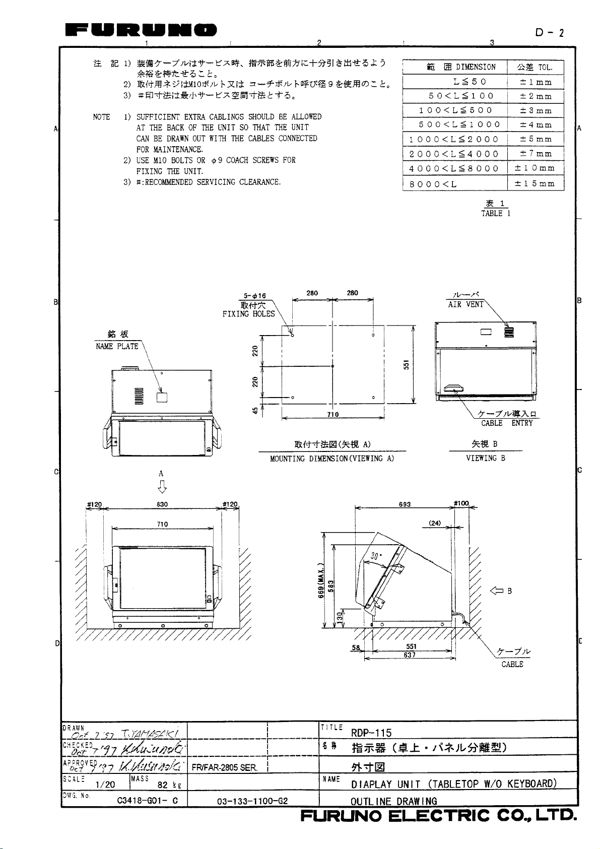
Display Unit (tabletop type, separate control panel)......................................................D-2
Control Unit ...................................................................................................................D-3
Display Unit (console type) ...........................................................................................D-4
Radar Scanner Unit........................................................................................................D-5
Radar Scanner Unit........................................................................................................D-6
LIST OF INSTALLATION MATERIALS, ACCESSORIES AND SPARE PARTS ........... L-1
ii
Page 7
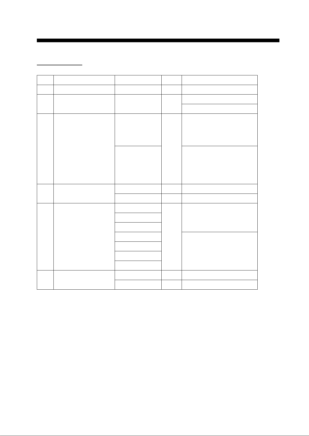
EQUIPMENT LISTS
Complete set
.oNemaNepyTytQskrameR
1tinurennacS1
2tinuyalpsiD511-PDR1 epyttnuomlatsedeP
epytpotelbaT
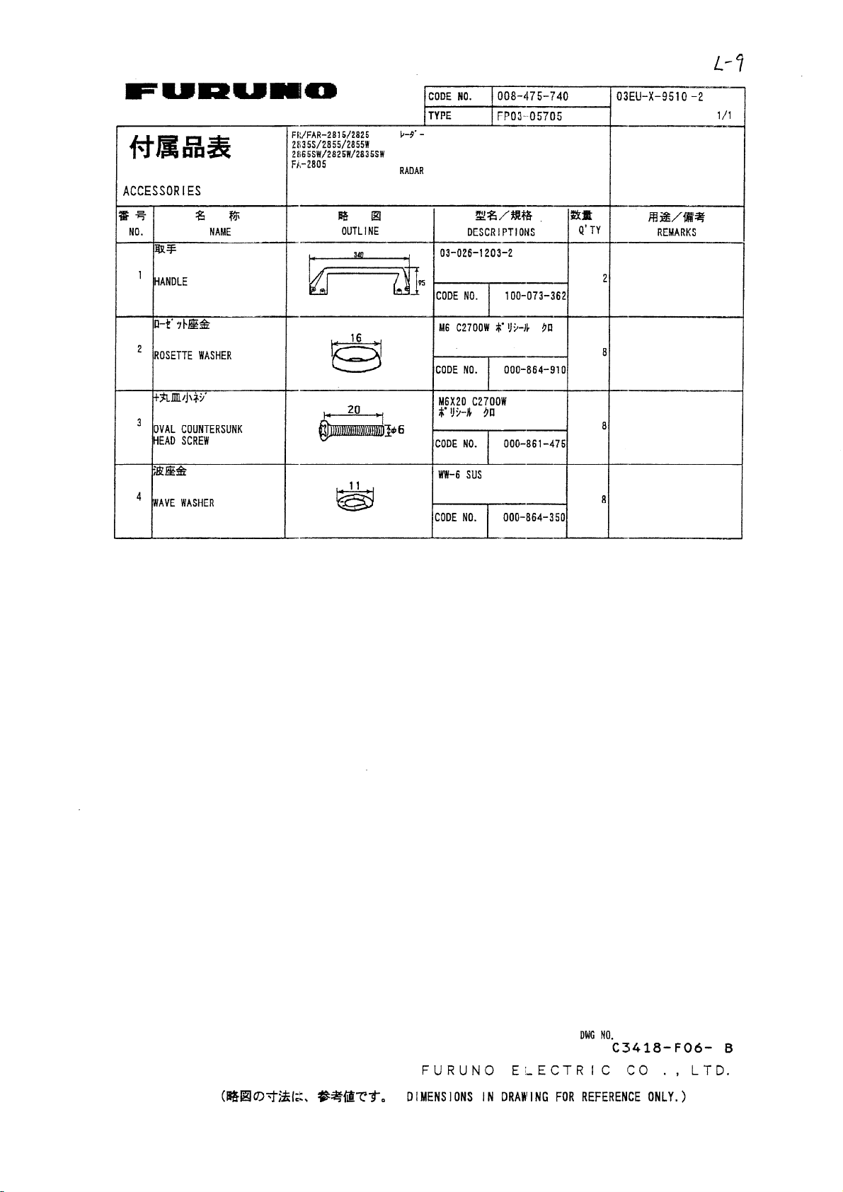
3seirosseccA01750-30PFtes1,tinulortnocni-tliubroF
10750-30PF
40750-30PF
50750-30PF
481-331-30
03750-30PF,tinulortnocetarapesroF
10750-30PF
30750-30PF
40750-30PF
50750-30PF
1181-331-30
4slairetamnoitallatsnI40191-30PCtes1tinurennacsroF
20641-30PCtes1tinuyalpsidroF
5elbaclangiS*m51*3784-WR1romraon
*m02*3784-WR
*m03*3784-WR
*m51*5986-WRromra/w
*m02*5986-WR
*m03*5986-WR
*m05*5986-WR
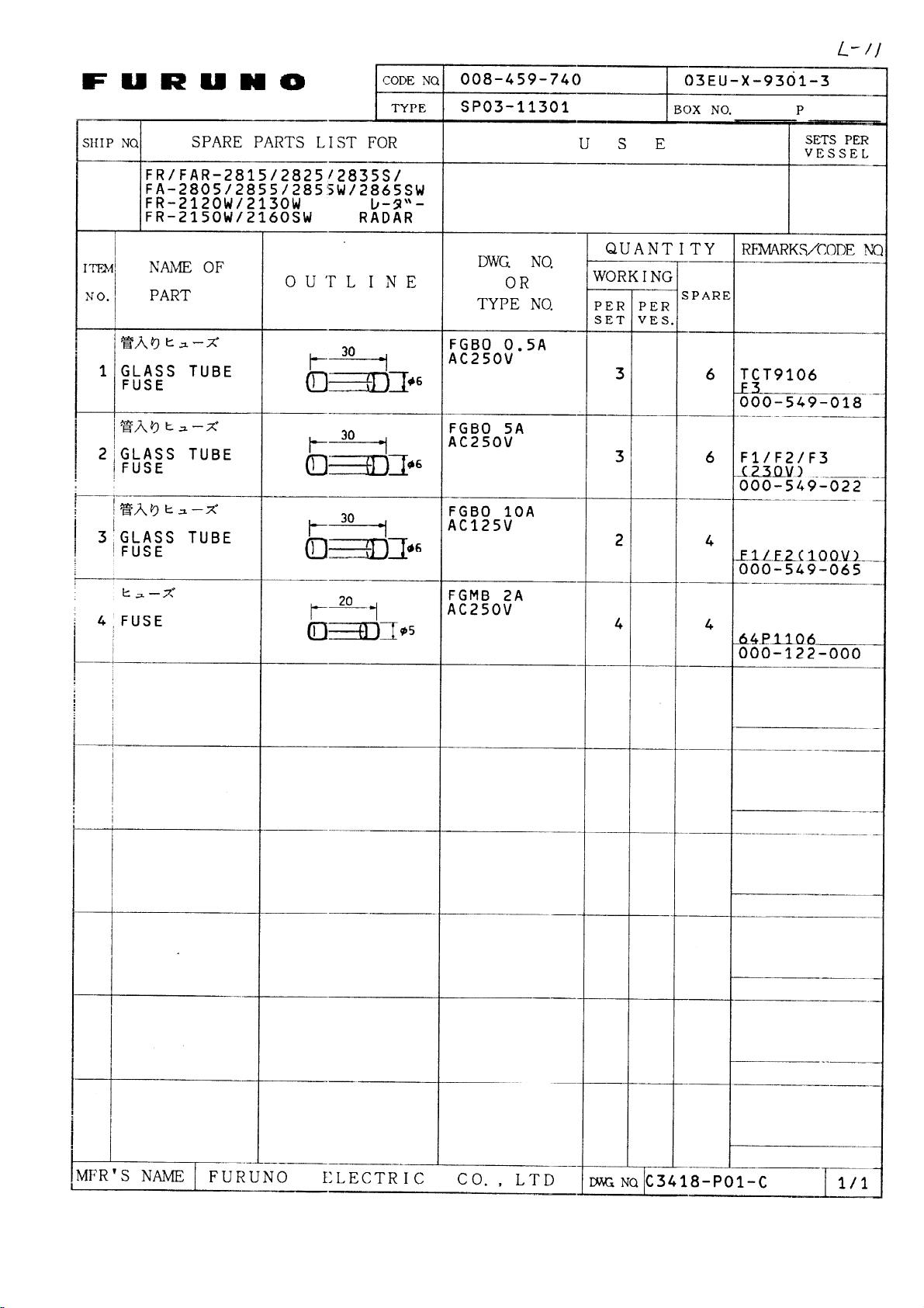
6straperapS20980-30PStes1tinurennacsroF
10311-30PStes1tinuyalpsidroF
iii
Page 8

Optional equipment
.oNemaNepyT.oNedoCskrameR
1spirgdnaH07-30PO024-324-800tinuyalpsidroF
2etalpgnixifdracM331-30PO004-254-800
3dooH4750-30PF018-954-800
4revoctinuyalpsiD621-30PO028-954-800tinulortnocni-tliub/wpotelbaT
721-30PO067-954-800tinulortnocetarapes/wpotelbaT
821-30PO098-954-800tnuomlatsedeP
5tinuyalpsiD
tiknoisrevnoc
6lenaplortnoC
etalpgnixif
7/rettolpoediV
pamradaR
8retrevnocoryG2-8-CG025-644-800slairetamnoitallatsnihtiW
9hctiwsretnI7-JR
01rezzublanretxE12-30PO790-030-000rotcennochtiw,m1
11ecnamrofreP
rotinom
21tinuegnaR
tiknoisrevnoc
1-921-30PO038-954-800ni-tliub/epytpotelbatmorfstrevnoC
2-921-30PO014-254-800
1-031-30PO009-954-800etarapes/epytpotelbatmorfstrevnoC
2-031-30PO034-254-800
131-30PO019-954-800potelbatottnuomlatsedepmorfstrevnoC
1-231-30PO029-954-800potelbatottnuomlatsedepmorfstrevnoC
2-231-30PO054-254-800
431-30PO043-164-800ottinulortnocepytetarapesgninetsafroF
52-PRradarOMIrofyrotadnaM
03-MPradarOMIrofyrotadnaM
1-011-30PO016-644-800mkoT
tnuomlatsedepottinulortnoc
tnuomlatsedepottinulortnoc
tinulortnocni-tliub/epyt
tinulortnocetarapes/epyt
potelbata
31tinuegnaR
tiknoisrevnoc
41tinuyalpsidroloC141-DC
51tinuyalpsidevalS0008-DMF
61tinuremrofsnarT8571-UR614-030-000CAV001otCAV022strevnoC
71tinuremrofsnarT3081-UR024-030-000CAV001otCAV044strevnoC
81hctiwsretnI8-JR
91tinuecafretnI0032-FIradarOMIrofyrotadnaM
2-011-30PO002-254-800msoT
iv
Page 9
1. MOUNTING
1.1 Scanner Unit
Mounting considerations
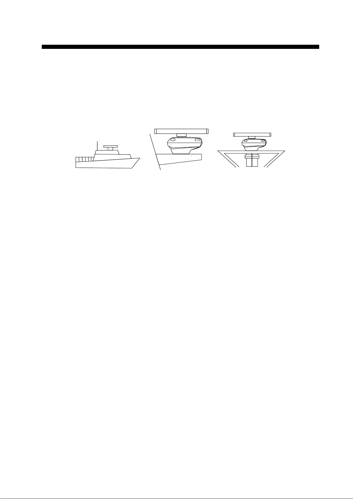
• The scanner unit is generally installed either on top of the wheelhouse or on the radar mast,
on a suitable platform. Locate the scanner unit where there is a good all-round view.
(a) On bridge (b) Common mast (c) Radar mast
Figure 1-1 Mounting methods
• No funnel, mast or derrick should be within the vertical beamwidth of the scanner in the bow
direction, especially zero degrees ±5°, to prevent blind sectors and false echoes on the radar
picture.
• It is rarely possible to place the scanner unit where a completely clear view in all directions
is available. Thus, you should determine the angular width and relative bearing of any shadow
sectors for their influence on the radar at the first opportunity after fitting.
• Locate the antenna of a direction finder clear of the scanner unit to prevent interference to
the direction finder. A separation of more than two meters is recommended.
• To lessen the chance of picking up electrical interference, avoid where possible routing the
signal cable near other onboard electrical equipment. Also avoid running the cable in parallel with power cables.
• A magnetic compass will be affected if placed too close to the scanner unit. Observe the
following compass safe distances to prevent deviation of a magnetic compass: Standard
compass,1.70 m (FR-2815), 2.10 m (FR-2825), Steering compass, 1.90 m (FR-2815), 1.20
m (FR-2825).
• Do not paint the radiator aperture, to ensure proper emission of the radar waves.
• The signal cable run between the scanner and the display is available in lengths of 15 m
(standard), 20 m, and 30 m. Whatever length is used it must be unbroken; namely, no splicing allowed.
• The scanner base is made of cast aluminum. To prevent electrolytic corrosion of the scanner
base, use the seal washers and corrosion-proof rubber mat and ground the unit with the
ground wire (supplied).
• Deposits and fumes from a funnel or other exhaust vent can adversely affect the aerial performance and hot gases may distort the radiator portion. The scanner unit must not be mounted
where the temperature is more than 70°C.
• Leave sufficient space around the unit for maintenance and servicing. See the scanner unit
outline drawing for recommended maintenance space.
1-1
Page 10
Assembling the scanner unit
CAUTION
The scanner unit consists of the scanner radiator and the scanner unit chassis, and they are
packed separately. Fasten the scanner radiator to the scanner unit chassis as follows:
1) For the XN20AF, XN24AF, attach two guide pins to the underside of the scanner radiator.
2) Remove the waveguide cap from the radiator bracket. The cap may be discarded.
3) Coat the waveguide flange with anticorrosive sealant as shown in Figure 1-2.
10 mm
Hole for
a guide pin
5 mm
Figure 1-2 Coating the waveguide flange with anticorrosive sealant
4) Coat fixing holes for the scanner radiator with anticorrosive sealant.
5) Grease the O-ring and set it to the O-ring groove of the radiator flange.
6) Set the scanner radiator to the radiator bracket.
O-ring
Anticorrosive sealant
Hole for
a guide pin
7) For the XN20AF, XN24AF, coat hex bolts (M8 x 40, slotted washer head, 8pcs.) with
anticorrosive sealant and use them to loosely fasten the scanner radiator to the scanner unit
chassis. For the XN12AF, coat hex bolts, flat washers and spring washers with anticorrosive sealant and use them to loosely fasten the scanner radiator to the scanner unit chassis.
8) Remove two guide pins (inserted at step 1), and then tighten fixing bolts.
CAUTION
Be sure to remove the guide pins.
Injury may result if the guide pins loosen
and fall.
1-2
Page 11
Antenna radiator
CAUTION
Radiator bracket
Guide pin
(XN20AF,
XN24AF
only)
O-ring
Hex bolt (M8X40), 8 pcs.
(XN20AF, XN24AF only)
Hex bolt (M8X35), 8 pcs.
Flat washer
Spring washer
(XN12AF only)
Figure 1-3 Fastening the radiator to the radiator bracket
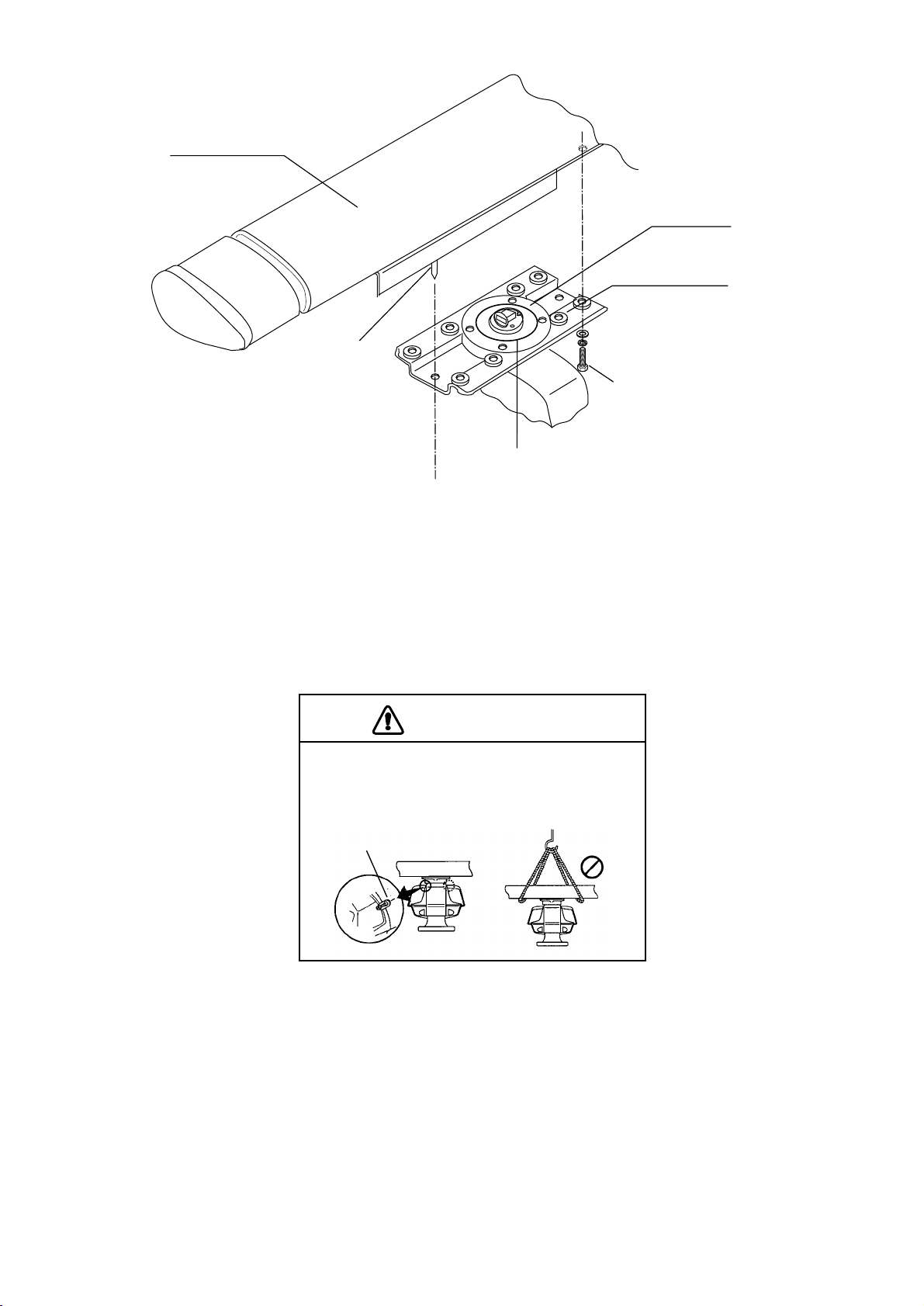
Fastening the scanner unit to the mounting platform
Waveguide
The scanner unit may be assembled before hoisting it to the mounting platform. However, do
not lift the scanner unit by the radiator. Always hold the unit by its housing. When using a crane
or hoist, lift the unit by the hoist rings which should be fastened to the bolt fixing covers of the
scanner housing.
CAUTION
DO NOT lift the antenna unit by the radiator;
lift it by the hoist rings. (Be sure to remove
rings after hoisting the antenna unit.)
Hoist
ring
1) Construct a suitable mounting platform referring to the outline drawing at the back of the
manual.
2) Drill four mounting holes of 15 mm diameter and one cable entry hole of about 50 mm
diameter in the mounting platform.
NO!
3) Lay the rubber mat (supplied) on the mounting platform.
1 - 3
Page 12
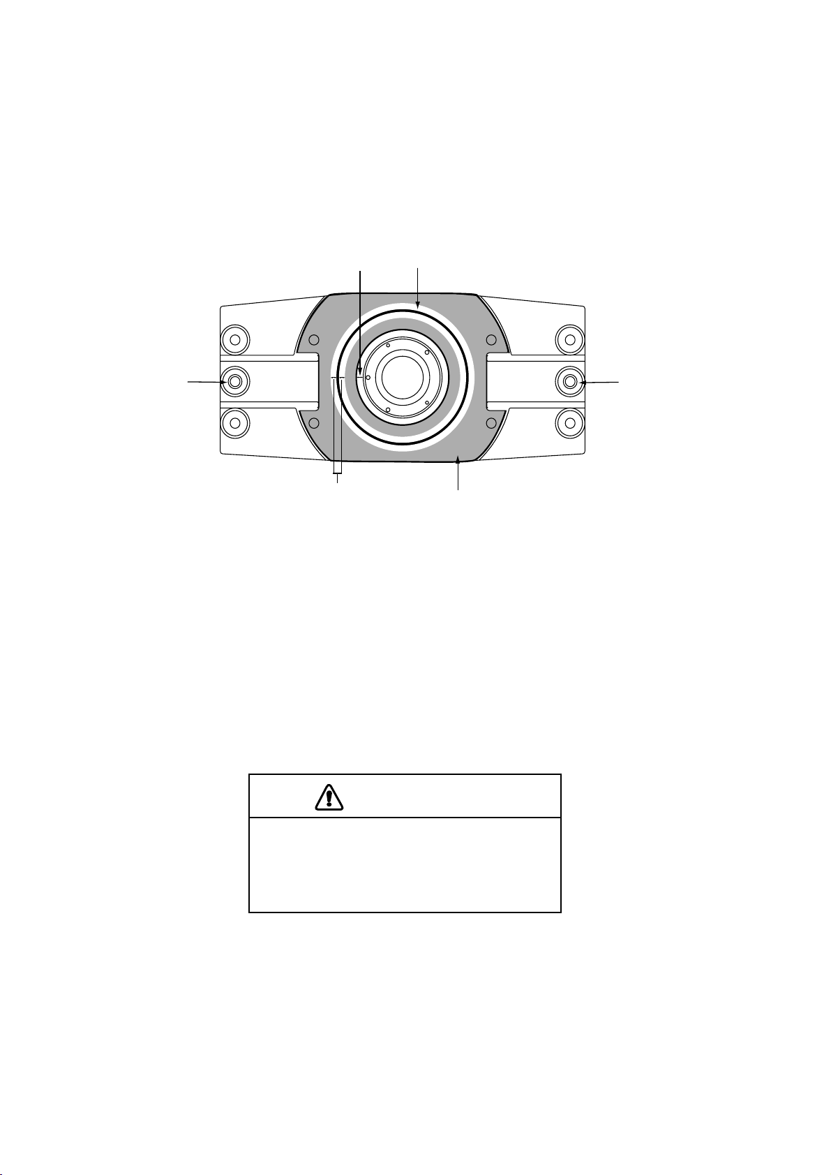
4) Place the scanner unit on the rubber mat orienting the unit so the bow mark on its base is
facing the ship’s bow.
Ground
terminal
Rubber
mat
Bow mark
Figure 1-4 Scanner unit, front view
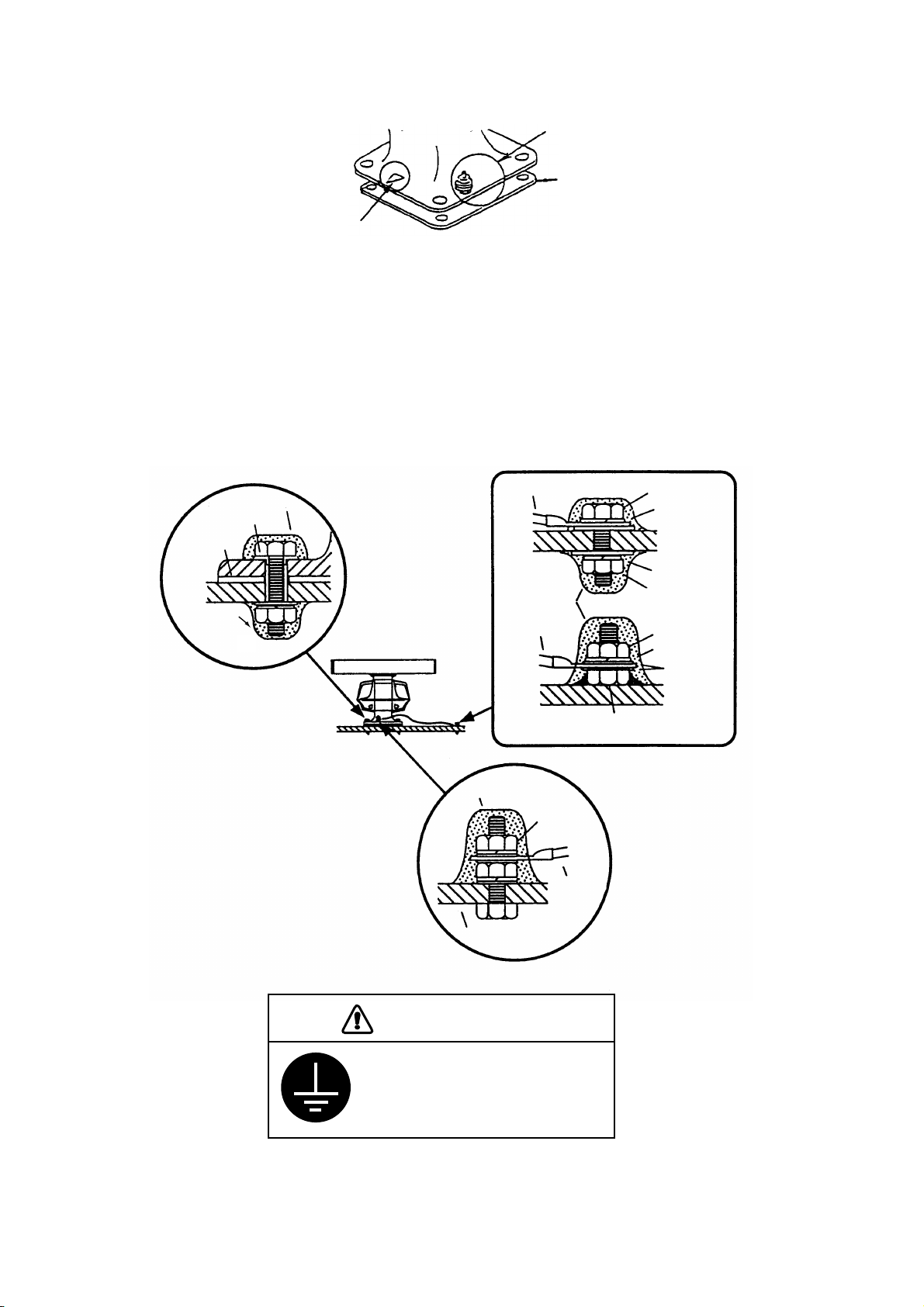
5) Fasten the scanner unit to the mounting platform with M12x60 hex bolts, nuts, flat washers
and seal washers.
6) Using hex bolt (M6x25), nut (M6) and flat washer (M6) establish the ground system on the
mounting platform as shown in Figure 1-5. The location should be within 370 mm of the
ground terminal on the scanner unit. Connect the ground wire (RW-4747, 370 mm, supplied) between the grounding point and ground terminal on the scanner unit. Coat the entire
ground system with silicone sealant (supplied).
Anticorrosive sealant
Seal washer
Rubber mat
Anticorrosive
sealant
Ground wire
Anticorrosive
sealant
Ground wire
Anticorrosive sealant
Ground
terminal
Ground
wire
Antenna base
Hex bolt
Spring washer
Spring washer
Hex nut
OR
Hex nut
Spring washer
Flat washer
Hex bolt welded to
ship’s superstructure
1 - 4
CAUTION
Ground the equipment to
prevent electrical shock
and mutual interference.
Figure 1-5 Fastening the antenna unit to the mounting location
Page 13
1.2 Mounting the Display Unit
The display unit is designed to be mounted on a tabletop or on a pedestal (option).
Before mounting the display unit
If Gyro Converter GC-8 (option) is to be used, install and setup the GYRO PROCESSOR
Board before mounting the display unit, because of the difficulty involved if done after the unit
is mounted. Instructions for installation and setup are in Chapter 4.
Siting considerations
Locate the display unit on the bridge in a place where it can be viewed and operated conveniently. In addition, consider the points noted in the figure which follows.
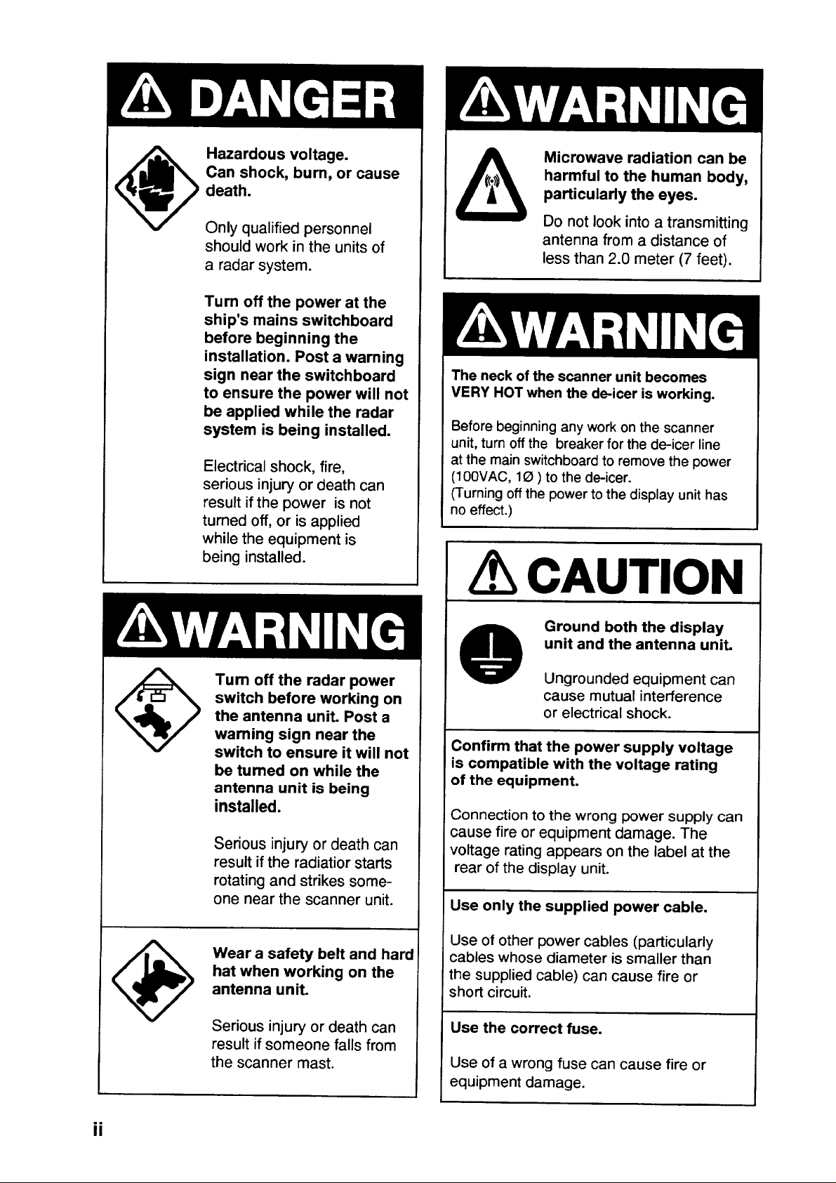
CAUTION
A magnetic compass will be affected if
placed too close to the display unit.
The minimum compass safe distances
for magnetic compasses are
standard compass:1.6 m
steering compass: 1.2 m
Consider the points mentioned below
when selecting a mounting location for the
display unit.
•
The orientation of the display unit should
be so the operator views the screen while
facing the bow. This makes determination
of position much easier.
• The location should be free of water spray.
• The daylight bright type radar display
provides excellent visibility even in direct
sunlight. However, locate the unit out of
direct sunlight and away from heat sources
because of heat that can build up inside
the cabinet.
• The mounting location should be deter mined considering the length of the signal
cable between the antenna unit and the
display unit. (The signal cable comes in
lengths of 15, 20 or 30 meters; maximum
100 meters.)
• Leave sufficient space around the unit for
maintenance and servicing. See the display
unit outline drawing for recommended
maintenance space.
1 - 5
Page 14
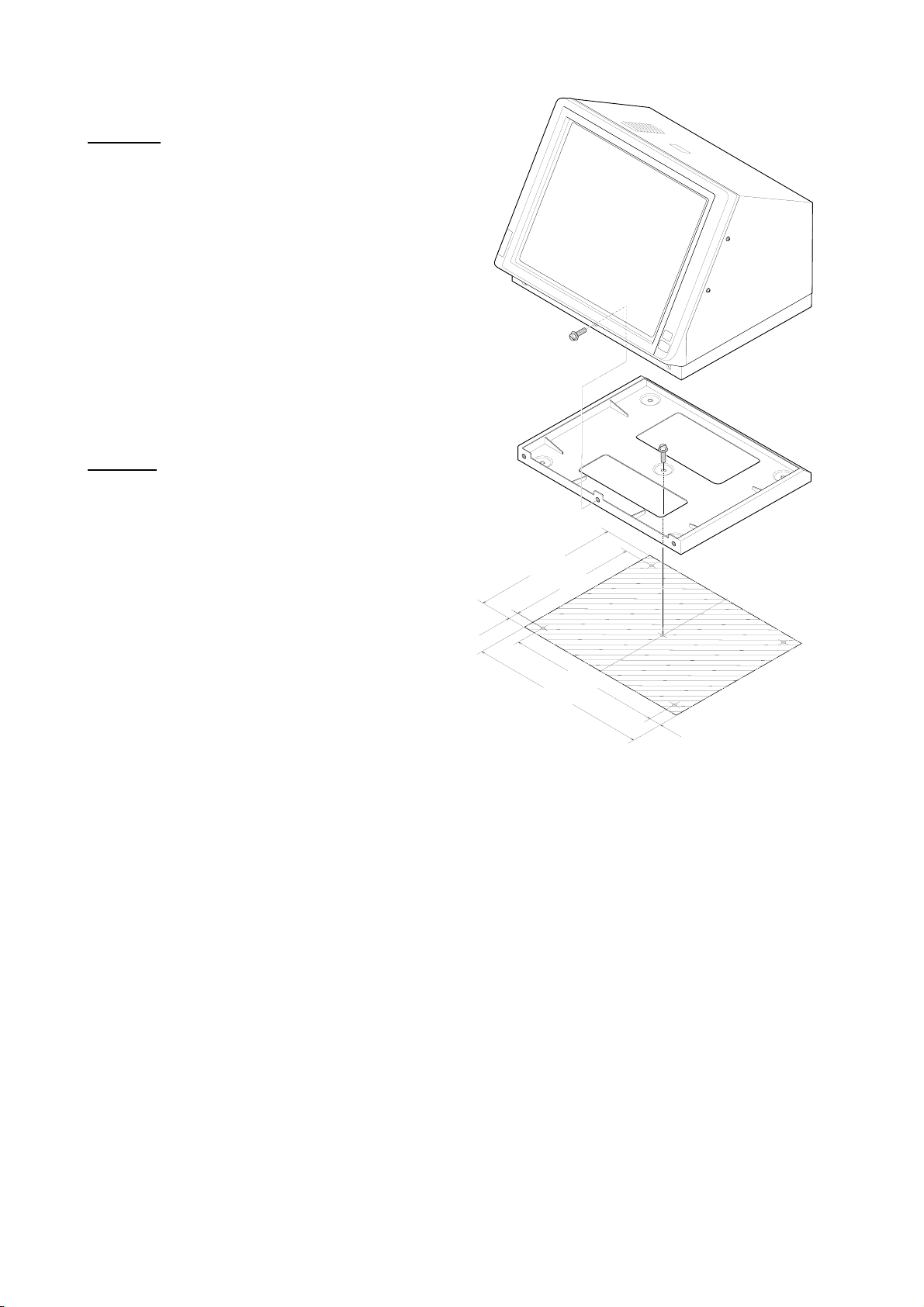
Mounting procedure
Tabletop
1) Unfasten the three M10 bolts at the front of
the display unit and separate the mounting base
from the display unit.
2) Drill five holes of 12mm diameter in the tabletop.
3) Secure the mounting base to the tabletop by
using M10 nuts, bolts and flat washers.
4) Place the display unit on the mounting base
and fasten it to the mounting base with the bolts
removed in step 1.
Pedestal
Fix the pedestal to the mounting location with M12
nuts, bolts and washers. (The cable gland is at the
bottom of the pedestal.) See the outline drawing at
the back of this manual.
529.5
460
1.3 Mounting the Separate Type Control Panel
The separate type control panel connects to the display unit with a connection cable. Nonslip rubber
feet (supplied) can be attached to the bottom of
the control panel. The panel can be permanently
fixed to a tabletop with the control panel fixing
plate kit (option).
70
560
644
42
Figure 1-6 Mounting dimensions for
tabletop mount display unit
1-6
Page 15
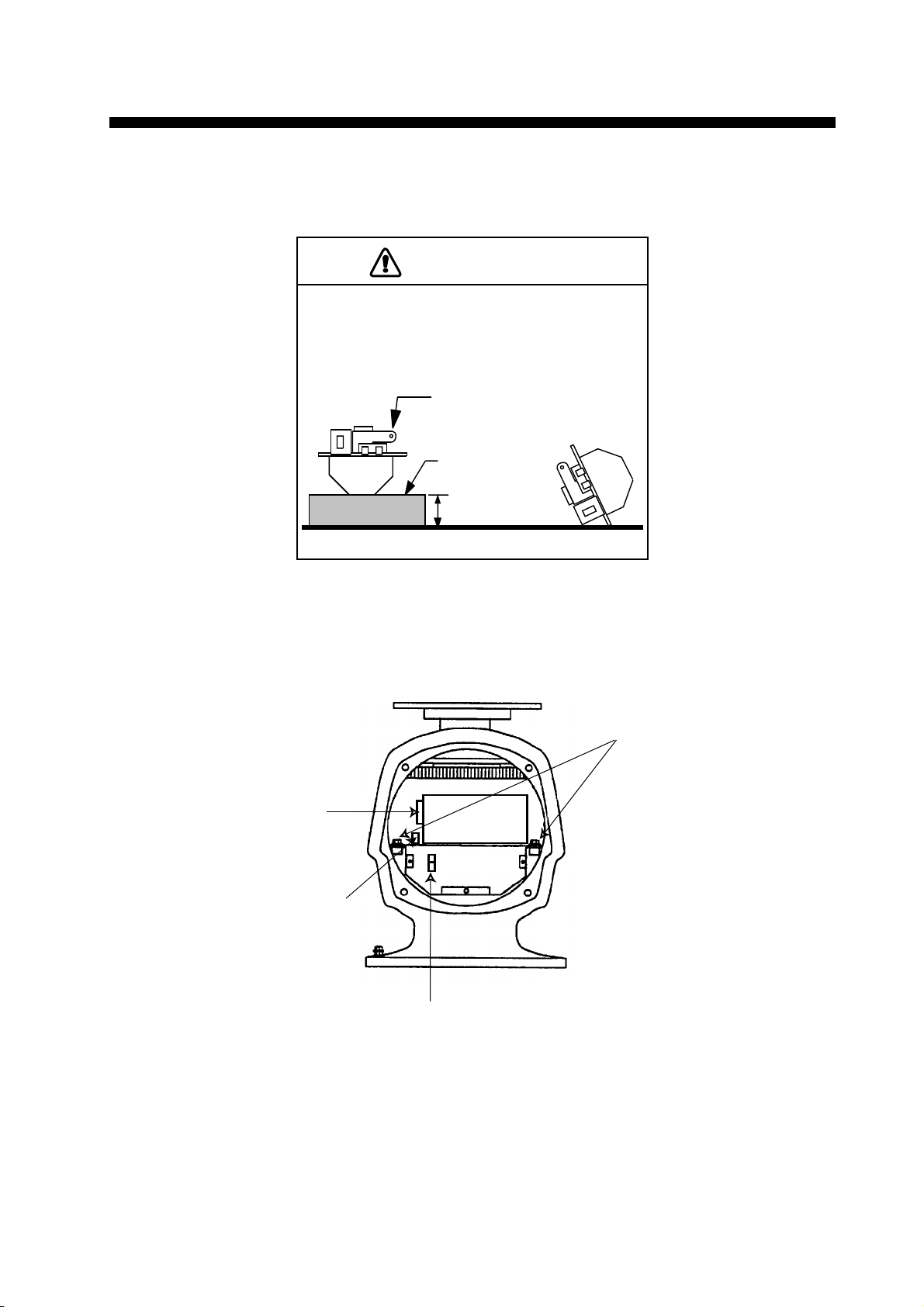
2.1 Scanner Unit
The magnetron in the transceiver module will demagnetize if it contacts ferrous material. When
dismounting the transceiver module, lay it on its
side or on top of non-ferrous material as shown
below.
2. CONNECTIONS
CAUTION
Transceiver module
(magnetron inside)
Non-ferrous
block
Height more
than 5 cm
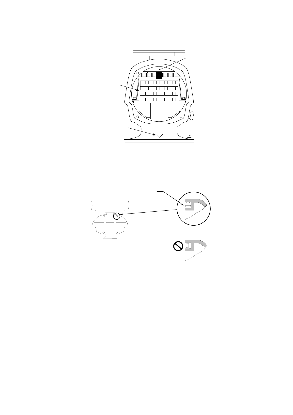
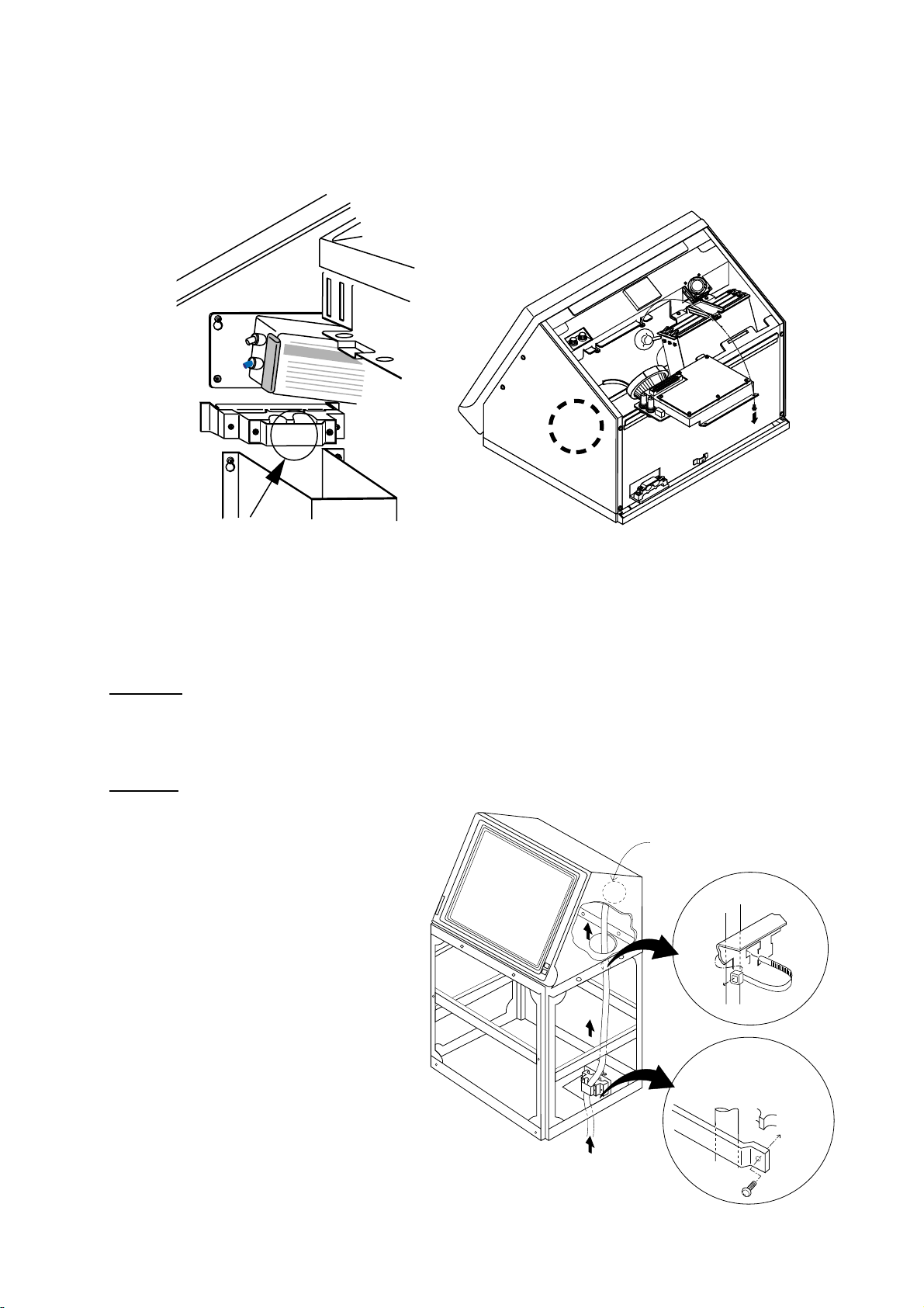
1) Open the scanner unit cover.
2) Disconnect plugs P611, P801 and P821.
3) Unfasten the transceiver module (two bolts). Remove the transceiver module.
Fixing
bolts
J611
J801
J821
Figure 2-1 Scanner unit, front view
2-1
Page 16
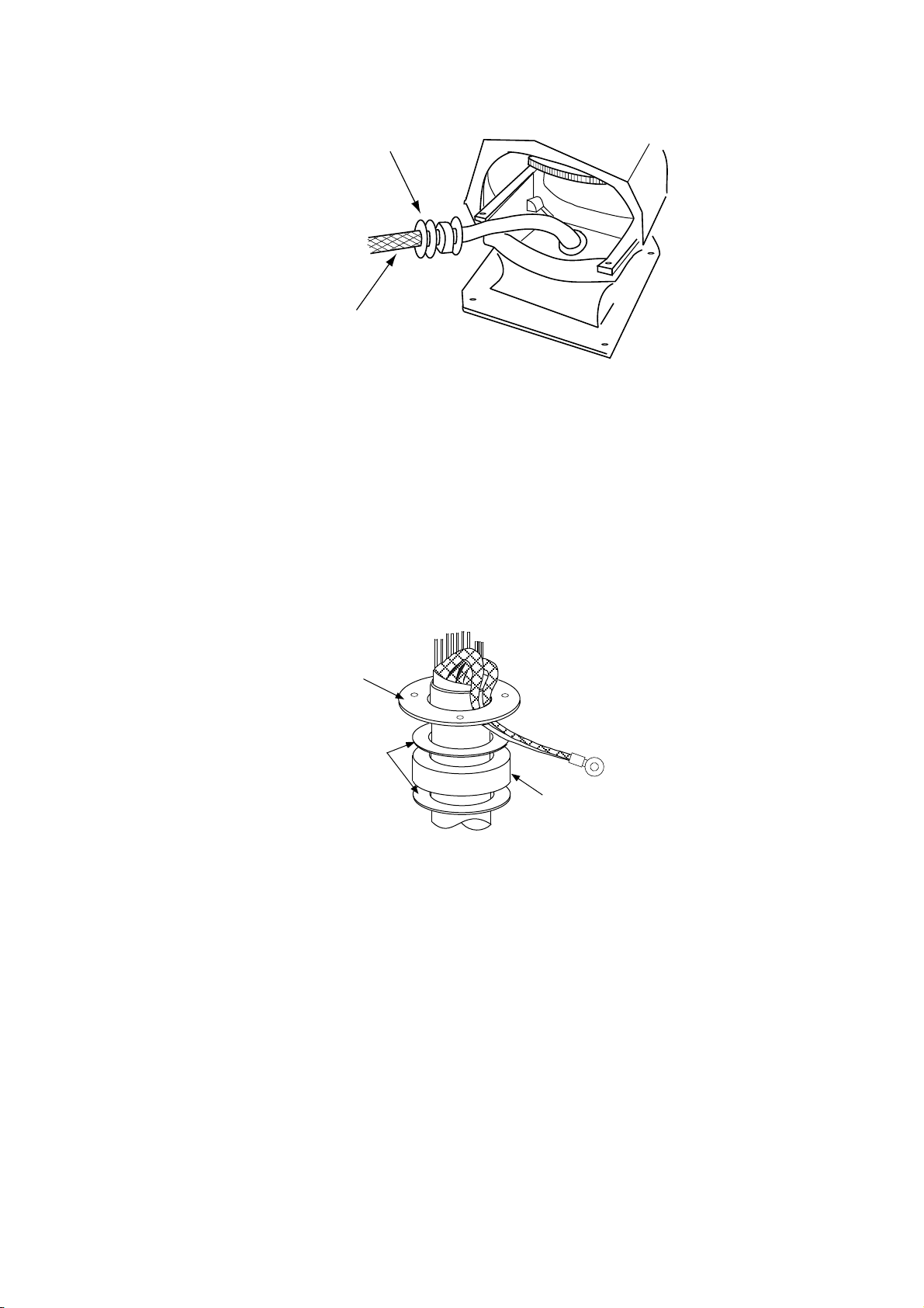
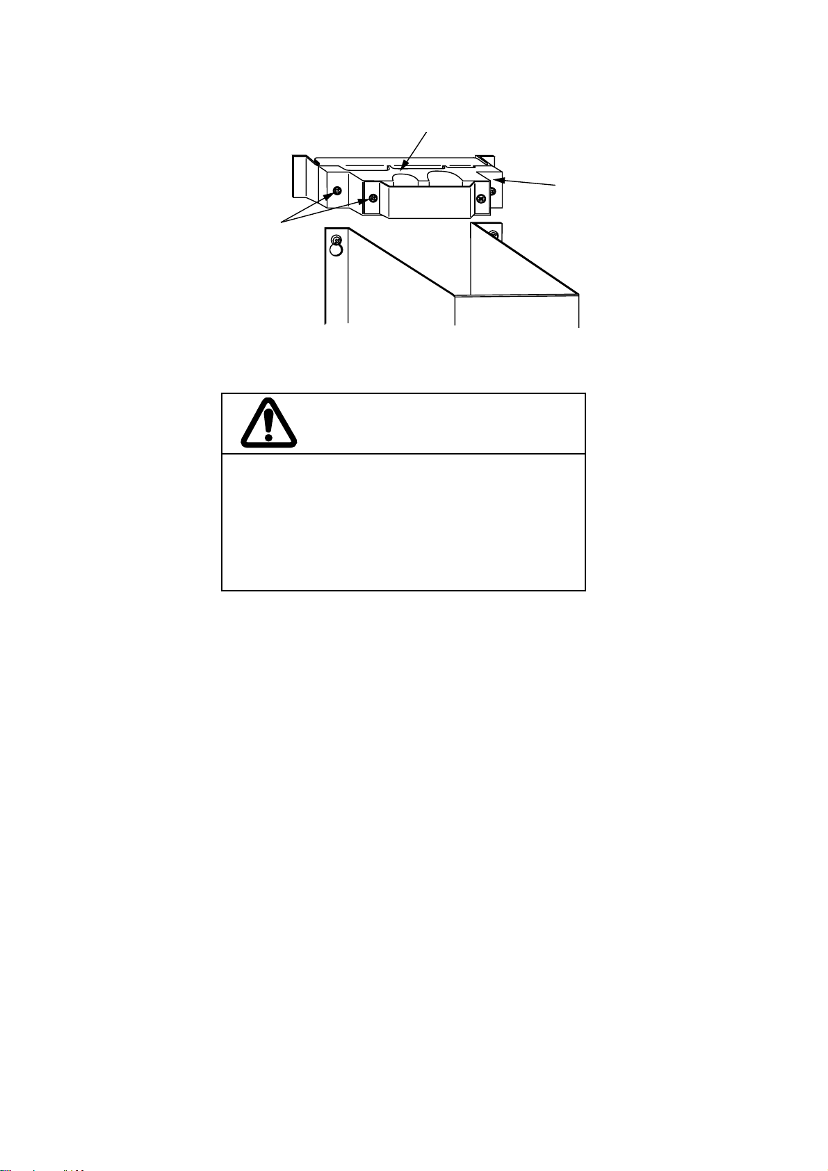
4) Unfasten the four fixing bolts on the cable gland at the base of the scanner unit. Remove
clamping ring, rubber gasket and washers.
From left: Clamping ring,
washer, rubber gasket
and washer
Signal cable
Figure 2-2 Scanner unit, front view, cover removed
5) Pass the signal cable through the cable entry hole in the scanner unit mounting platform.
Trim the cable so about 80 cm of it protrudes past the cable gland.
6) Slide the clamping ring, washer, rubber gasket and washer onto the cable in that order.
7) Fabricate the signal cable as shown on page 2-4 (signal cable RW-4873), or page 2-5 (signal cable RW-6875).
8) Referring to Figure 2-3, pass the outer and inner shields between the signal cable and the
clamping ring. Fasten the cable gland.
Clamping
ring
Washers
Rubber
gasket
Figure 2-3 Passing cable shields between cable and clamping ring
9) Connect the signal cable to the terminal board RTB801 by referring to the interconnection
diagram. Leave “slack” in the coaxial wire to prevent breakage.
10) Bind cores of cables with cable ties.
11) Mount the transceiver module. Connect plugs P611, P801 and P821. Fasten the shield to
the ground terminal on the transceiver module.
2-2
Page 17
12) If the scanner is mounted 2° or more left of ship’s bow, adjust the position of S901 so it
becomes “on” (contact between #1 and #2 on pcb MP-3795). T o access S901, open the bow
side cover; S901 is above the drive gear.
S901
RTB801
Bow mark
1 2 345 6 7891011121314
15 16 171819 20 212223 24 25 26 2728
Figure 2-4 Scanner unit, front view
13) Confirm that all screws are tightened and all wiring is properly made. Coat waterproofing
gasket, bolts and tapping holes of scanner unit with silicone grease. Check that the waterproofing gasket is seated as shown in Figure 2-5. Close the scanner unit cover.
Coat gasket with silicone grease.
DO NOT use silicone sealant.
CORRECT
WRONG
Figure 2-5 Correct seating of waterproofing gasket
2 - 3
Page 18
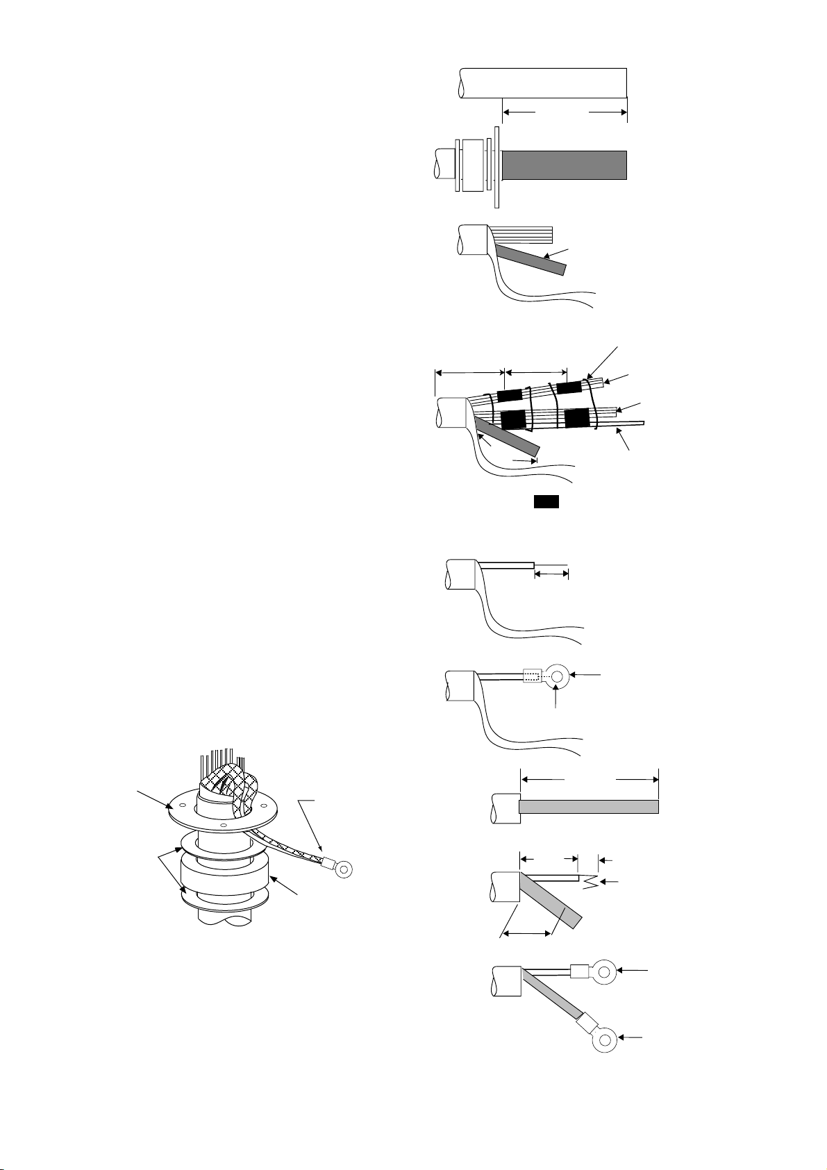
Fabricating signal cable RW-4873
VINYL SHEATH
1) Remove the vinyl sheath by 450 mm.
2) Slide the clamping ring, washer , rubber gasket and washer onto the signal cable in that
order.
3) Unravel the outer shield to expose the cores
in the outer layer. Then, unravel the inner
shield to expose the cores in the inner layer.
Label all inner cores to aid in identification.
4) Attach EMI cores to all inner cores and all
outer cores, and tie them with cable ties, etc..
Note:There are two types of the EMI core,
thick and thin.
5) Trim each core (except coaxial wire) considering its location on the terminal board.
6) Trim the inner and outer shields leaving 500
mm each. Twist shields together and attach
crimp-on lug FV5.5-4 (blue, ø4).
7) Remove insulation of each core by about 6
mm. Fix crimp-on lug FV1.25-M3 (red, ø3)
to each core.
8) Fabricate the coaxial cable. Make the length
10 mm longer than the shield to prevent wire
strain. Attach crimp-on lug FVD1.25-3 (red,
ø3) to coaxial cable.
under
100mm
500mm
450 mm
70-130mm
6 mm
Inner shield
Cable tie
Outer cores
Inner cores
Coax cable
= EMI cores
Outer cores:RFC-13(thick)
Inner cores:RFC-10(thin)
Red(φ3)
Clamping
ring
Washers
2-4
Rubber
gasket
Figure 2-7 How to ground
signal cable RW-4873
Crimp-on lug
(FV5.5-4, Blue, φ4)
Crimp-on lug(FV1.25-M3)
75 mm
2C-2V
50 mm
45 mm
Cut here
Figure 2-6 How to fabricate
signal cable RW-4873
6 mm
Fold four times
Red(φ3)
(FVD1.25-3)
Red(φ3)
(FVD1.25-M3)
Page 19
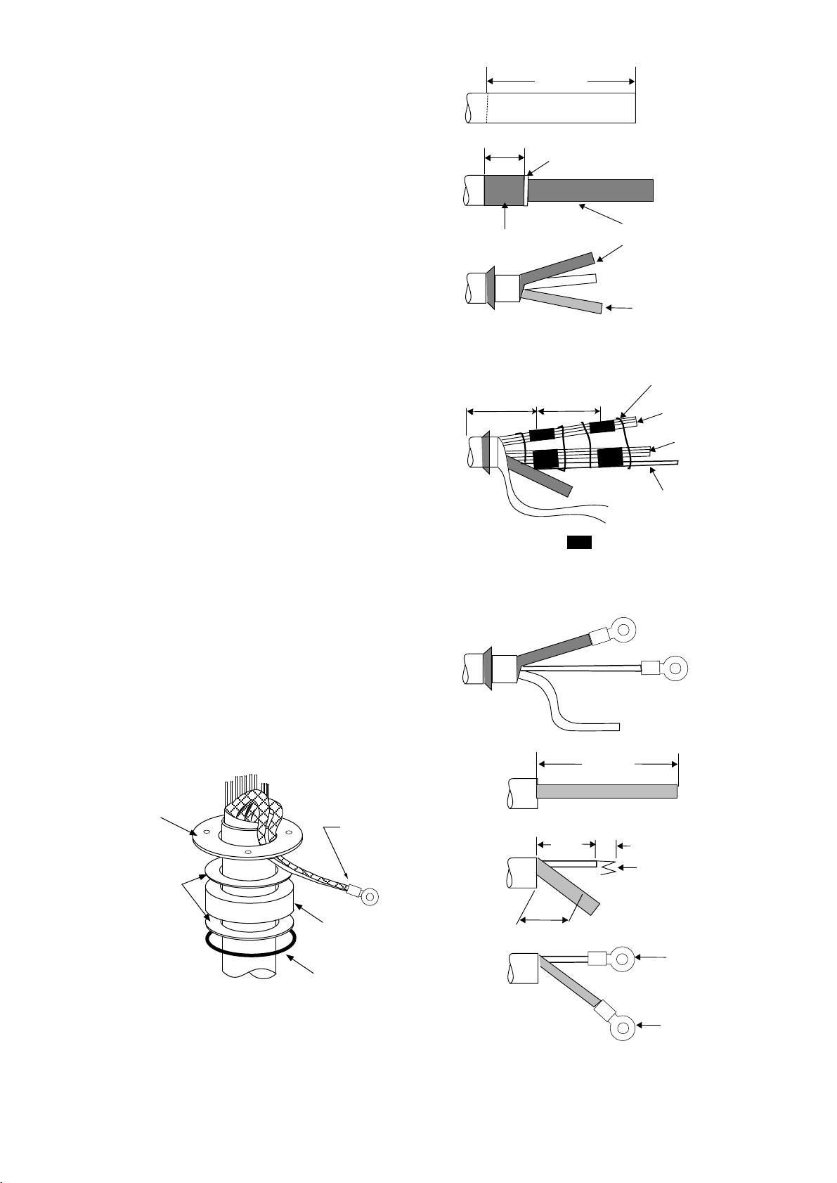
Fabricating signal cable RW-6895
500 mm
1) Remove the anti-corrosive sheath by 500
mm. Remove the armor and vinyl sheath
leaving 50 mm each approximately.
2) Fold back the armor and trim to suitable
length. Then, slide the washer, rubber gasket, washer and clamping ring onto the cable
in that order.
3) Unravel the outer shield to expose the cores
in the outer layer. Then, unravel the inner
shield to expose the cores in the inner layer .
Label all inner cores for later identification.
4) Attach EMI cores to all inner cores and outer
cores, and tie them with cable ties, etc..
Note: There are two types of EMI core,
thick and thin.
5) Trim each core (except coaxial core) con-
sidering its location on the terminal board.
ANTICORROSIVE SHEATH
50 mm
Vinyl sheath
Armor
under
100mm
70-130mm
Outer sheath
Inner shield
Cable tie
Outer cores
Inner cores
Coax cable
6) T rim the inner and outer shields leaving 50
cm each. Twist shields together and attach
crimp-on lug FV5.5-4 (blue, ø4).
7) Remove insulation of each core by 6 mm
approximately. Attach crimp-on lug
FV1.25-M3 (red, ø3) to each core.
8) Fabricate the coaxial cable. Make the length
10 mm longer than the shield to prevent wire
strain. Attach crimp-on lug FVD1.25-3 (red,
ø3) to coaxial cable.
Clamping
ring
Washers
Crimp-on lug
(FV5.5-4, Blue, φ4)
Rubber
gasket
Armor
2C-2V
Shield
45 mm
50 mm
=EMI cores
Outer cores:RFC-13(thick)
Inner cores:RFC-10(thin)
FV2-4(Blue)
Crimp-on lug
FV1.25-M3
Coax cable
75 mm
6 mm
Fold four times
Cut here
Red(φ3)
(FVD1.25-3)
Figure 2-9 How to ground
signal cable RW-6895
Red(φ3)
(FVD1.25-M3)
Figure 2-8 How to fabricate
signal cable RW-6895
2-5
Page 20
2.2 Display Unit Connections
Two cables are terminated at the display unit: the signal cable RW-4873 or RW-6895 and the
power cable. The signal cable, available in lengths of 15m, 20m or 30m, comes with a connector preattached to it for connection to the display unit.
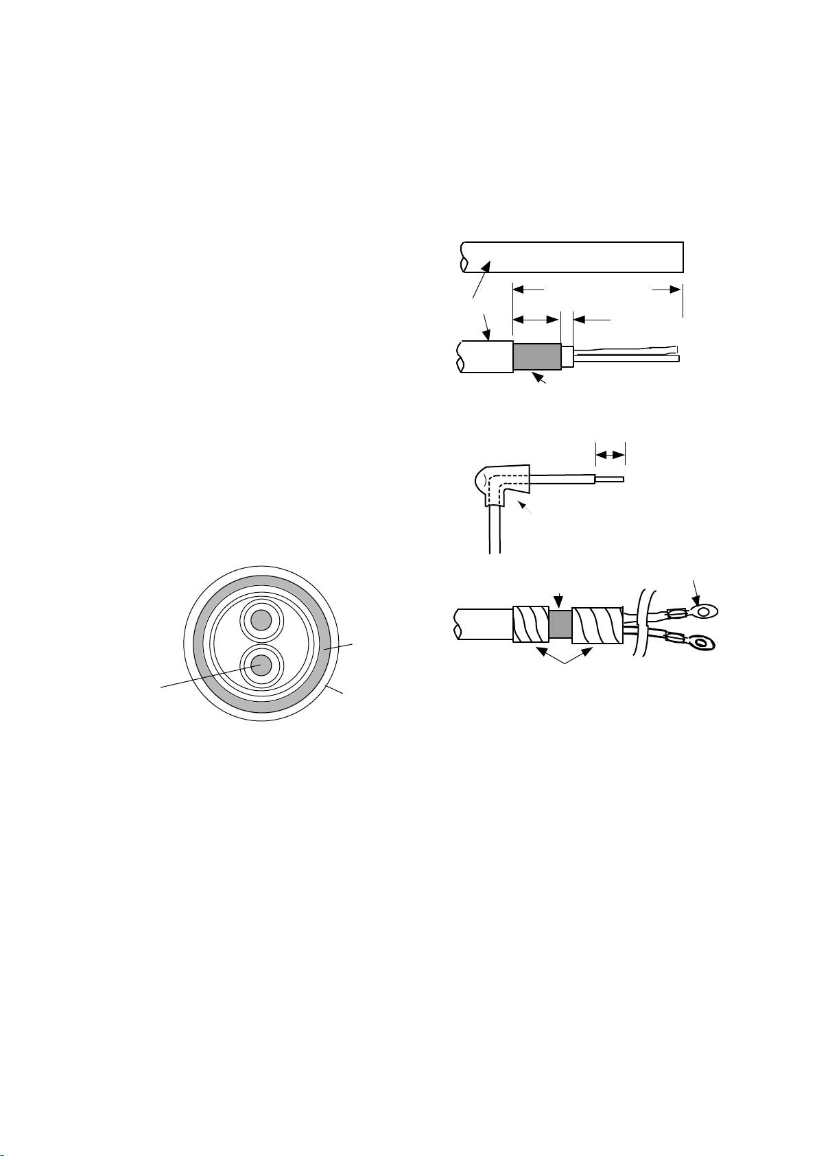
Fabricating power cable DPYCY -3.5
1) Remove the vinyl jacket by 150mm.
2) Cut off jute tape wrapped around the braided
shield.
3) Unravel the braided shield to expose the cores
by about 120mm.
4) Slip the terminal cap onto the core.
5) Remove insulation of cores by about 10mm.
Fix crimp-on lugs FV5.5-4 to the cores and
braided shield.
6) Cover the braided shield with vinyl tape, leav-
ing the portion which will lie inside the cable
clamp untaped.
Armor
(a)
Vinyl jacket
(b)
(c)
(d)
DPYCY-3.5
Approx. 150 mm
15 mm
Armor
Terminal cap
Clamp here
5 mm
10 mm
FV5.5-4
Core
S = 3.5 mm
φ = 2.4 mm
Taping
2
Vinyl sheath
Figure 2-10 How to fabricate
power cable DPYCY-3.5
(sectional view)
2-6
Page 21
Leading in cables to the display unit
To lead in cables easily, unfasten the cable clamp at the right side of the display unit.
Cable
clamp
Figure 2-11 Location of cable clamp inside the display unit
Tabletop
Cables can be led in through the cable gland at the rear or underside of the unit.
Pedestal
Lead in cables through the cable gland
at the bottom right-hand side of the ped-
Process cable same as
on tabletop type
estal. Pass cables through the cable
clamp and tighten the cable clamp. Fix
cables to the pedestal frame with cable
ties as shown in Figure 2-12. Finally,
pass cables through the cable clamp at
the right side of the display unit and then
tighten the cable clamp.
Leaving sheath
intact, pass cable
through cable
clamp
Figure 2-12 How to lead in cables
through the pedestal
2 - 7
Page 22
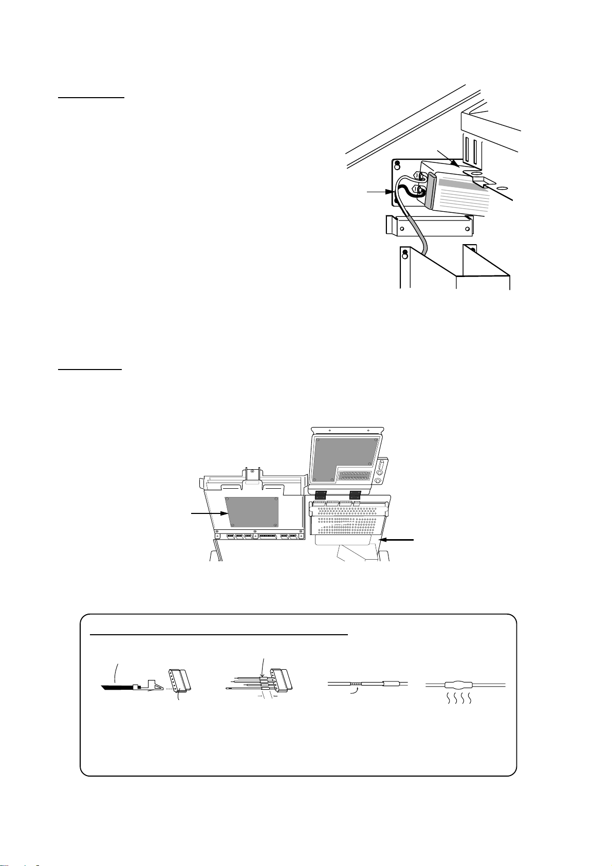
Connections
Power cable
Connect the power cable to the filter at the right
hand side of the display unit. Cover the filter terminals with the terminal caps (supplied) to insulate the terminals.
Filter
Power
cable
Figure 2-13 Location of filter
inside the display unit
Gyro signal
Solder the 5 pin and 3 pin VH connectors (supplied) to the gyrocompass cable. Plug in the
connectors on the GYRO CONVERTER Board. For further details, see page 4-2.
GYRO CONVERTER
Board
Rear panel
Figure 2-14 Location of GYRO CONVERTER Board
HOW TO ATTACH NH CONNECTOR TO SIGNAL CABLE
NH connector wire
Shrink tubing
2-8
NH connector
housing
1 Insert NH connector
wire into NH connector
housing.
20mm
2 Cut shrink tubing
in 20 mm lengths and
slip onto each wire.
Solder
3 Solder connector
to signal cable.
4 Heat shrink
tubing with soldering iron.
Page 23
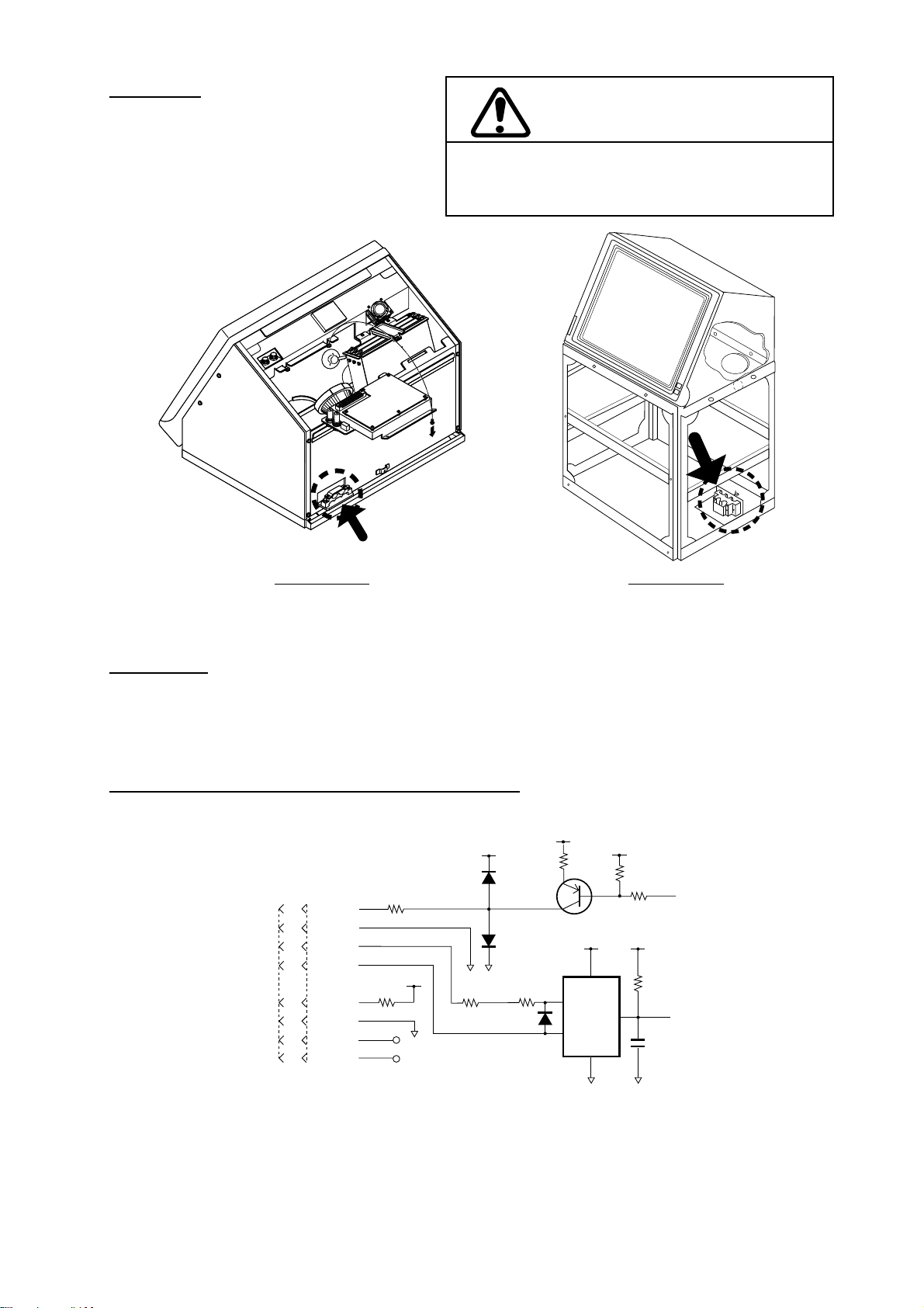
Grounding
The display unit must be grounded from
a grounding stud having a wing nut located at the point shown in Figure 2-15.
Tabletop type Pedestal type
CAUTION
An ungrounded unit can cause electrical shock when
its metallic parts are touched and give off or receive
electromagnetic interference.
Figure 2-15 Grounding the display unit
Radar buoy
Solder the radar buoy signal line to the "BUOY" connector on the VDA Board. Connect the
trigger line to the corresponding connector on the INT Board.
Signal input/output circuit (INT Board INT-9170)
Nav data
+5V
J450
1 TXD1-H
2 TXD1-C
3 RXD1-H
4 RXD1-C
+5V
5 DTR1-H
6 DTR1-C
7 DSR1-H
8 DSR1-C
2SC1015
+5V
PC900V
1
A
2
X
Vcc
GND
6
OUT
5
+5V
+5V+5V
4
Figure 2-16 INT Board circuit
For other input/output circuits, see the circuit diagram of the INT Board at the back of this
manual.
2 - 9
Page 24

Table 2-1 Input and output signals on the INT Board
emanlangiSnoemaN
bcp
langiStupnI
langisoryG*4J
goldeepS
langis
)edit(langis
)deeps(langis
youbradaR
langis
yalpsidetomeR
langis
elgnaredduR
langis
langiStuptuO
APRAlanretxE
langis
GOL844Jnip3,HN.cte,mn/seslup002
rotacidnitnerruC
VAN
rotacidnitnerruC
VAN
YOUB
TOR
rotcennoC
.on
*5J
954Jnip4,HNdesutoN
ESRUOC
064Jnip3,HNdesutoN
DEEPS
RADAR
RADAR-TXE
7-JRro
REDDUR
APRA-TXE444Jnip8,HN5082-AF,gniraeb,gnidaeh
544Jnip4,HN
854Jnip8,HN
464Jnip7,HN
epyt
rotcennoC
nip5,HV
nip3,HV
elbacilppA
tnempiuqe
skrameR
bcpnO:*
)noitpo(6011P46A
reggirtxT
yalpsidevalS
langis
langisrezzuBZUB-TXE154Jnip3,HN3-12-30POlangisevirdrezzub
langisrezzuB
)CA(
langisrotinoM944Jnip01,HN,suonorhcnysREV
8-JR8-JR654Jnip4,HN
atadSNIATAD.SNI554Jnip5,HN
7-JR7-JR754Jnip51,HN
EVALS244J
)CA(
langiStuptuO/tupnI
344J
ZUB-TXE
254Jnip2,HNpma/wrekaepSlangisrekaeps
nip8,HN,141-DC,041-DC
nip8,HN
,gniraeb,gnidaeh
,005-DG
,008-DMF
1*0008-DMF
roftinuyalpsiD:1*
seires0082-RF
desuebnacradar
yalpsidevalssa
.tinu
)tam
reggirtxT,oediv
,suonorhcnysROH
-rofCSTN(oediv
2-10
atadvaNATADVAN054Jnip8,HN
atadAPRAATADAPRA454Jnip5,HN
Page 25

J458
J464
J441
J445
J452
J463
J467
J443
DTB-2#1
J442
J461
J460
#8
J444
J448
J457
J450
J454
J455
J451
Figure 2-17 Location of connectors on the INT Board
J449
J459
J456
2 - 11
Page 26
Grounding cables and covering unused cable slots in the cable clamp
Cover unused cable
slots with aluminum tape.
Ground shield
of cables by
Fasten ground wire
of cables by fixing
screws for cable clamp.
cable clamp.
Figure 2-18 Cable clamp
CAUTION
1) The display unit must be grounded. Failure to
ground the unit may cause electrical shock when its
metallic parts are touched and give off or receive
electromagnetic interference.
2) Cover unused cable slots in the cable clamp with
aluminum tape to prevent foreign objects from
falling into the display unit through the cable slots.
2-12
Page 27

2.3 Changing Power Specifications
This radar can be powered by 100V AC or 220V AC, and is set at the factory for connection to
a 100V power supply. To power the unit by 220V AC, remove jumper JP13 on the POWER
Board as shown in the procedure below.
CAUTION
Turn off the power before executing the procedure
shown below.
Procedure
1) Turn off the power.
2) Unfasten the four screws circled in the
illustration at right.
3) Remove the power assembly.
4) Remove the power assembly cover.
5) For 220V power supply , remove jumper
wire JP13 on the POWER Board.
6) Mount the power assembly.
rewoPeriwrepmuJ
31PJ
JP13
RT-9183
C42
CAV001trohS
CAV022evomeR
C8
C6
2 - 13
Page 28

3. INITIALIZATION AND ADJUSTMENT
3.1 Menus for Initialization and Adjustment
Accessing the menus
The menus for initialization and adjustment of this radar are locked to prevent adjustment by
the user. To access them;
1) Turn off the power.
2) Turn on the #4 segment of DIP Switch S1 on the SPU Board.
4
S1
1
Figure 3-1 Display unit (top view, cover removed) and SPU Board
Menu operation
1) Press the [RADAR MENU] key.
2) Press appropriate numeric key to select menu desired.
3) Press numeric key to select item.
4) Press same numeric key pressed in step 3 to select option.
5) Press [ENTER] to register selection.
Menu description and menu tree
See pages 3-6 and 3-11, respectively.
Restoring default settings
1) Press [RADAR MENU] [0] [0] [2] [0] [0] [0] [0] to select FACT ORY DEFAUL T on the
INITIAL SETTING 4 menu.
2) Press [ENTER] key.
3) Wait for 10 seconds.
4) Turn power off, and on again.
3-1
Page 29

5) Press [RADAR MENU] [0] [0] [2] [0] [0] [0] to open the INITIAL SETTING 4 menu.
6)Confirm that FR-2815, 2825 is selected at MODEL.
3.2 Heading Alignment
Antenna unit mounted error (heading reed switch timing error) can be compensated at the display unit.
Correct bearing
relative to heading
Target
a
Antenna mounted error
to port (heading switch
advance)
000
010
350
020
340
330
320
310
300
290
280
270
260
250
240
230
220
210
200
030
150
160
190
170
180
Picture appears
deviated clockwise.
Figure 3-2 Heading alignment error
040
140
050
060
120
130
a
070
080
090
100
110
Apparent
position
of target
Apparent position
Target
b
Antenna mounted error
to starboard (heading
switch delayed)
of target
000
010
350
340
330
320
310
300
290
280
270
260
250
240
230
220
210
200
190
170
180
Picture appears
deviated counterclockwise.
b
020
030
040
050
060
070
080
090
Correct
100
110
bearing
120
relative to
130
140
heading
150
160
Procedure
1) Turn on the power. Press [RADAR MENU] [0] [0] [2] [2] to select HD ALIGN on the
INITIAL SETTING 1 menu.
2) Select a target echo (by gyrocompass, for example) at a range between 0.125 and 0.25nm,
preferably near the heading mark.
3) Operate the EBL control to bisect the target echo. (The value shown on the display is an-
tenna position in relation to ship's bow.)
4) Press [ENTER] to finish.
3.3 Adjusting Sweep T iming
Sweep timing differs with respect to the length of the signal cable between the antenna unit and
the display unit. Adjust sweep timing at installation to prevent the following symptoms:
• The echo of a "straight" target (for example, pier), on the 0.25nm range, will appear on the
display as being pulled inward or pushed outward. See Figure 3-3.
• The range of target echoes will also be incorrectly shown.
Correct Target pushed Target pushed
inward outward
3–2
Figure 3-3 Examples of correct
and incorrect sweep timings
Page 30

Procedure
1) Turn on the power . Press [RADAR MENU] [0] [0] [2] [3] to select TIMING ADJ on the
INITIAL SETTING 4 menu.
2) Transmit on the 0.25nm range.
3) Adjust radar picture controls to display picture properly.
4) Select a target echo which should be displayed straightly.
5) Adjust the VRM control to straighten the target echo.
6) Press the [ENTER] key.
3.4 Adjusting Video Signal Level
When the signal cable is very long, the video amplifier input level decreases, shrinking target
echoes. To prevent this, confirm (and adjust if necessary) video amplifier input level.
Procedure
1) Connect an oscilloscope to TP3 on the INT Board (INT-9170).
2) Transmit on the 12nm range. Take trigger at TP10 on the same board.
3) Adjust VR1 on the INT Board so the value of TP3 is 4Vpp. (For secondary display, adjust
VR2 for same level.)
VR2
VR1
INT Board
TP3
Figure 3-4 Location of INT Board
3 - 3
Page 31

Page 32

Page 33

Page 34

Page 35

Page 36

Page 37

Page 38

Page 39

Page 40

Page 41

Page 42

Page 43

Page 44

Page 45

Page 46

Page 47

Setting method 2: by make and model of gyrocompass
Table 4-2 Setting GYRO CONVERTER Board by make and model of gyrocompass
rekaMsledoMnoitacificepSWS
ONURUF007-YGpetsCD
ztuhcsnA3,2dradnatSsuonorhcnysCA
6,4dradnatSsuonorhcnysCA
02dradnatSpetsCD
awagokoY
cetvaN
htialP(
)epyt
htialPIII/IITAGVANsuonorhcnysCA
cemikoT
yrrepS(
)epyt
ikasawaK18-XGsuonorhcnysCA
nworbamrA1-LKM,01-KM
nostreboR08-RKSpetsCD
3/2/A1/1-C
55-B,55-A
005/X003
003
3/2-SPI
05-ZMC
etoN
11/2/1-SE
002-GT
H/L732RP
12MG
41-KM
T/2/1-DOM
302/
0006-GTpetsCD
11-MGsuonorhcnysCA
4-DOM
/X052-ZMC
/002/001-ZMC
3/1/Z1-D,rJ1-C
/201/101-TLG
701/K601/301
011/A11-SE
0002/R222RP
IE-KN,NE-KN
041/031-RSpetsCD
0005/001-GT
/031/753-RP
71-SE,041
202/102-TLG
61-SE,021-RS
03/02/01-KM
,1531SEIRES
x081V001
zH06/05
x063
zH06/05
x063
x081V53
zH06/05
x063
petsCD
x081V53
zH06/05
x063
pets
x081V53
zH06/05
x063
zH06/05
x63
zH06/05
x09
petsCD
x081V07
x081V07
petsCD
x081V07
x081V42
zH06/05
x09
petsCD
x081V53
zH06/05
x09
petsCD
x081V05
x081V53
rotcellocnepo,eriw-5
V06/05:egatlovrotoR
V22:egatlovrotatS
V06/05:egatlovrotoR
V09:egatlovrotatS
)+(eriw-3,)-(MOC
suonorhcnysCA
V06/05:egatlovrotoR
V22:egatlovrotatS
x063suonorhcnysCDFFOFFOFFOFFOFFOFFONONO-NOFFO-omeR
)-(eriw-3,)+(MOC
suonorhcnysCA
V001:egatlovrotoR
V09:egatlovrotatS
)-(eriw-3,)+(MOC
V06/05:egatlovrotoR
V86:egatlovrotatS
suonorhcnysCA
V011/001:egatlovrotoR
V09:egatlovrotatS
suonorhcnysCA
V011/001:egatlovrotoR
V22:egatlovrotatS
)+(eriw-3,)-(MOC
rotcellocnepo,eriw-5
)-(eriw-3,)+(MOC
V001:egatlovrotoR
V09:egatlovrotatS
V011/001:egatlovrotoR
V09:egatlovrotatS
)-(eriw-3,)+(MOC
)+(eriw-3,)-(MOC
WS
WS
WS
WS
WS
WS
WS
WS
WS
1-1
2-1
3-1
4-1
5-1
6-1
7-1
8-1
1-2
NOFFOFFONOFFOFFONONO- FFOFFO,4#
FFOFFOFFOFFOFFOFFOFFOFFOFFONOFFO,1#
FFOFFOFFOFFOFFOFFOFFOFFOFFOFFOFFO,1#
NOFFOFFONOFFOFFONONO-NOFFO,4#
FFOFFOFFOFFOFFOFFOFFOFFOFFONOFFO,1#
NOFFOFFONOFFOFFONONO-NOFFO,4#
FFOFFOFFOFFOFFOFFOFFOFFOFFOFFOFFO,1#
NOFFOFFONOFFOFFONONO– NOFFO-omeR
FFOFFOFFOFFOFFOFFOFFOFFOFFOFFOFFO,1#
NONOFFOFFOFFOFFOFFOFFOFFOFFOFFO,1#
FFONOFFOFFOFFOFFOFFOFFOFFOFFOFFO,1#
NOFFOFFONOFFOFFONONO– FFOFFO,4#
NOFFOFFOFFONOFFOFFOFFO– FFOFFO,4#
NOFFOFFONOFFOFFONONO– FFOFFO,4#
NOFFOFFONOFFOFFONONO-NOFFO,4#
FFONOFFOFFOFFOFFOFFOFFOFFOFFOFFO,1#
NOFFOFFONOFFOFFONONO– NOFFO,4#
FFONOFFOFFOFFOFFOFFOFFOFFOFFOFFO,1#
NOFFOFFONOFFOFFONONO– FFOFFO,4#
NOFFOFFONOFFOFFONONO– NOFFO,4#
WS
2-2
3-2
1PJ2PJ3PJ4PJ5PJ
2#-1#1#
6#,5#
2#2#1#1#
3#,2#
2#1#1#1#
3#,2#
2#-2#2#
6#,5#
2#2#1#1#
3#,2#
2#-
ev
2#-2#2#
6#,5#
1#1#1#1#
3#,2#
2#–
ev
2#2#1#1#
3#,2#
1#1#1#1#
3#,2#
1#1#1#1#
3#,2#
2#– 1#1#
6#,5#
2#– 1#1#
6#,5#
2#– 1#1#
6#,5#
2#– 2#2#
6#,5#
1#1#1#1#
3#,2#
2#– 2#2#
6#,5#
1#1#1#1#
3#,2#
2#– 1#1#
6#,5#
2#– 2#2#
6#,5#
∗∗
∗∗
4-6
Page 48

Page 49

Page 50

Page 51

Page 52

Page 53

Page 54

Page 55

Page 56

Page 57

Page 58
Page 59

Page 60
Page 61

Page 62

Page 63

Page 64

Page 65
Page 66

Page 67

Page 68

Page 69

Page 70

Page 71

Page 72

Page 73

Page 74

 Loading...