

Page 1

Installation Manual
MARINE RADAR FR-2115-B/FR-2125-B
SAFETY INSTRUCTIONS................... i
EQUIPMENT LISTS ...........................iii
SYSTEM CONFIGURATION..............vi
1. MOUNTING
1.1 Antenna Unit.................................... 1-1
1.2 Processor Unit ................................. 1-6
1.3 Monitor............................................. 1-9
1.4 Control Unit.................................... 1-11
2. WIRING
2.1 Antenna Unit.................................... 2-1
2.2 Processor Unit ................................. 2-5
2.3 Monitor............................................. 2-8
2.4 Control Unit.................................... 2-10
2.5 External Equipment ....................... 2-11
2.6 AC Power Specification of
3. INITIALIZATION AND
ADJUSTMENT
3.1 Tuning Initialization.......................... 3-1
3.2 Accessing Menus for Initialization and
Adjustment ....................................... 3-1
3.3 Adjusting Video Signal Level...........3-1
3.4 Heading Alignment .......................... 3-2
3.5 Adjusting Sweep Timing ..................3-3
3.6 Suppressing Main Bang..................3-3
3.7 Confirming Magnetron Heater
Voltage ............................................3-4
3.8 Initial Setting Menus........................3-5
4. OPTIONAL EQUIPMENT
4.1 Gyro Converter GC-8 ......................4-1
4.2 ARP Board ARP-26......................... 4-7
4.3 RP Board RP-26.............................. 4-9
Processor Unit...............................2-13
4.4 Performance Monitor PM-30.........4-13
4.5 Alarm Kit ........................................ 4-14
4.6 AC-DC Conversion Kit...................4-15
PACKING LISTS.............................A-1
OUTLINE DRAWINGS....................D-1
INTERCONNECTION DIAGRAM...S-1
SCHEMATIC DIAGRAMS...............S-2
i
Page 2

(
C
9-52, Ashihara-cho,
Nishinomiya, Japan
Telephone: 0798-65-2111
Telefax: 0798-65-4200
All rights reserved.
Printed in Japan
PUB. No. IME-34830-H
TENI)
FR-2115/2125-B
Your Local Agent/Dealer
FIRST EDITION : JUL. 1999
H : NOV. 05, 2001
Page 3
SAFETY INSTRUCTIONS
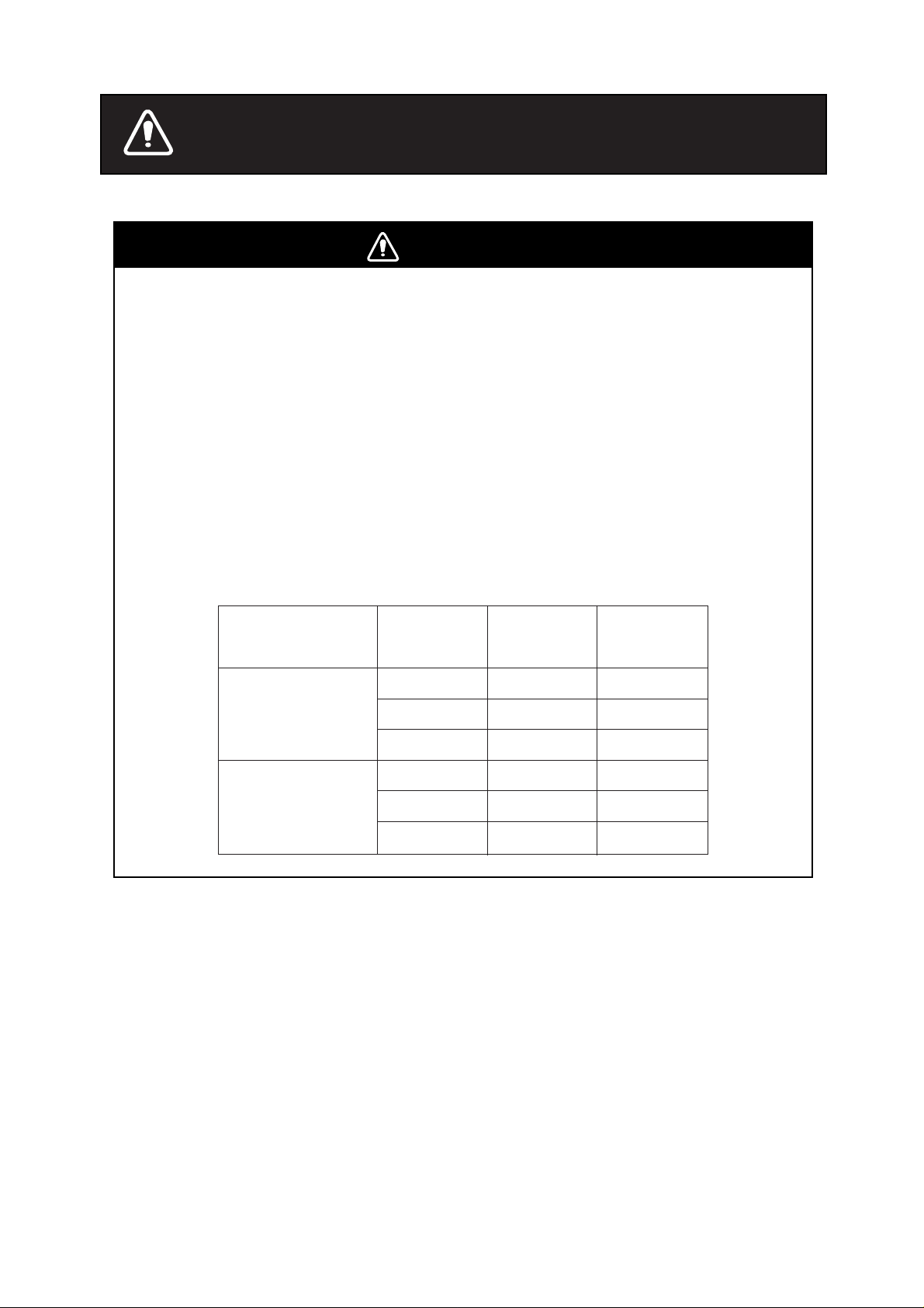
WARNING
Radio Frequency Radiation Hazard
The radar antenna emits electromagnetic radio frequency (RF) energy which can be
harmful, particularly to your eyes. Never look directly into the antenna aperture from a
close distance while the radar is in operation or expose yourself to the transmitting
antenna at a close distance.
Distances at which RF radiation levels of 100 and 10 W/m
below.
Note: If the antenna unit is installed at a close distance in front of the wheel house,
your administration may require halt of transmission within a certain sector of antenna
revolution. This is possible - ask your FURUNO representative or dealer to provide
this feature.
Model
FR-2115-B
FR-2125-B
Radiator
type
XN12AF
XN20AF
XN24AF
XN12AF
XN20AF
XN24AF
Distance to
100 W/m
2
exist are given in the table
Distance to
2
point
0.1 m 3.5 m
0.1 m 3.5 m
0.1 m 3.5 m
1.1 m 1.4 m
1.1 m 10.0 m
1.1 m 10.0 m
10 W/m
point
2
i
Page 4
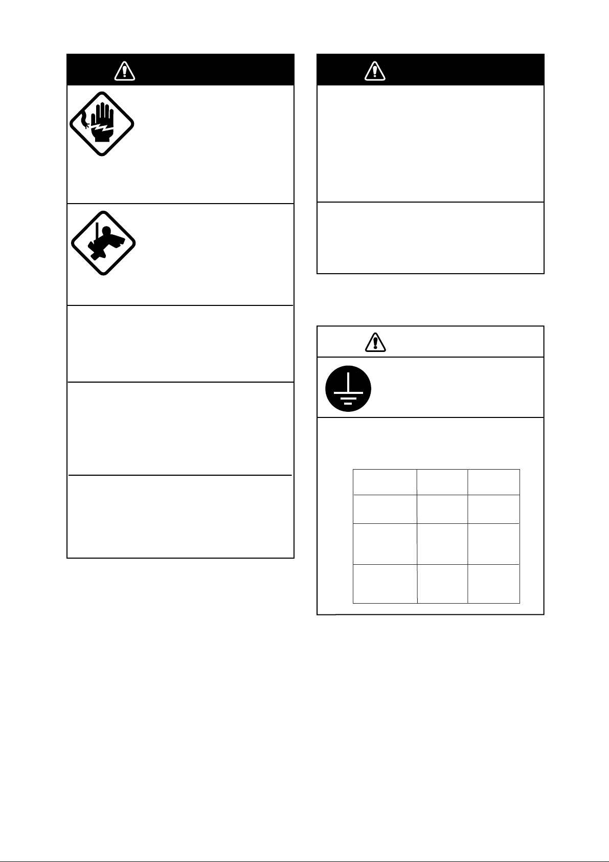
WARNING
WARNING
Do not open the equipment
unless totally familiar with
electrical circuits and
service manual.
ELECTRICAL
SHOCK
HAZARD
Construct a suitable service platform
from which to install the antenna unit.
Serious injury or death can result if someone falls from the radar antenna mast.
Turn off the power at the mains switchboard before beginning the installation.
Only qualified personnel
should work inside the
equipment.
Wear a safety belt and hard
hat when working on the
antenna unit.
Serious injury or death can
result if someone falls from
the radar antenna mast.
Be sure that the power supply is
compatible with the voltage rating of
the equipment.
Connection of an incorrect power supply
can cause fire or equipment damage. The
voltage rating of the equipment appears
on the label above the power connector.
Use only the specified power cable.
Fire or equipment damage can result if a
different cable is used.
CAUTION
Ground the equipment to
prevent electrical shock and
mutual interference.
Fire, electrical shock or serious injury can
result if the power is left on or is applied
while the equipment is being installed.
Do not install the display unit where it
may get wet from rain or water splash.
Water in the display unit can result in fire,
electrical shock or equipment damage.
Observe the following compass safe
distances to prevent interference to a
magnetic compass:
Standard Steering
compass compass
Processor
unit
Antenna
unit
(FR-2115-B)
Antenna
unit
(FR-2125-B)
1.70 m 0.90 m
1.70 m 0.90 m
2.10 m 1.20 m
ii
Page 5
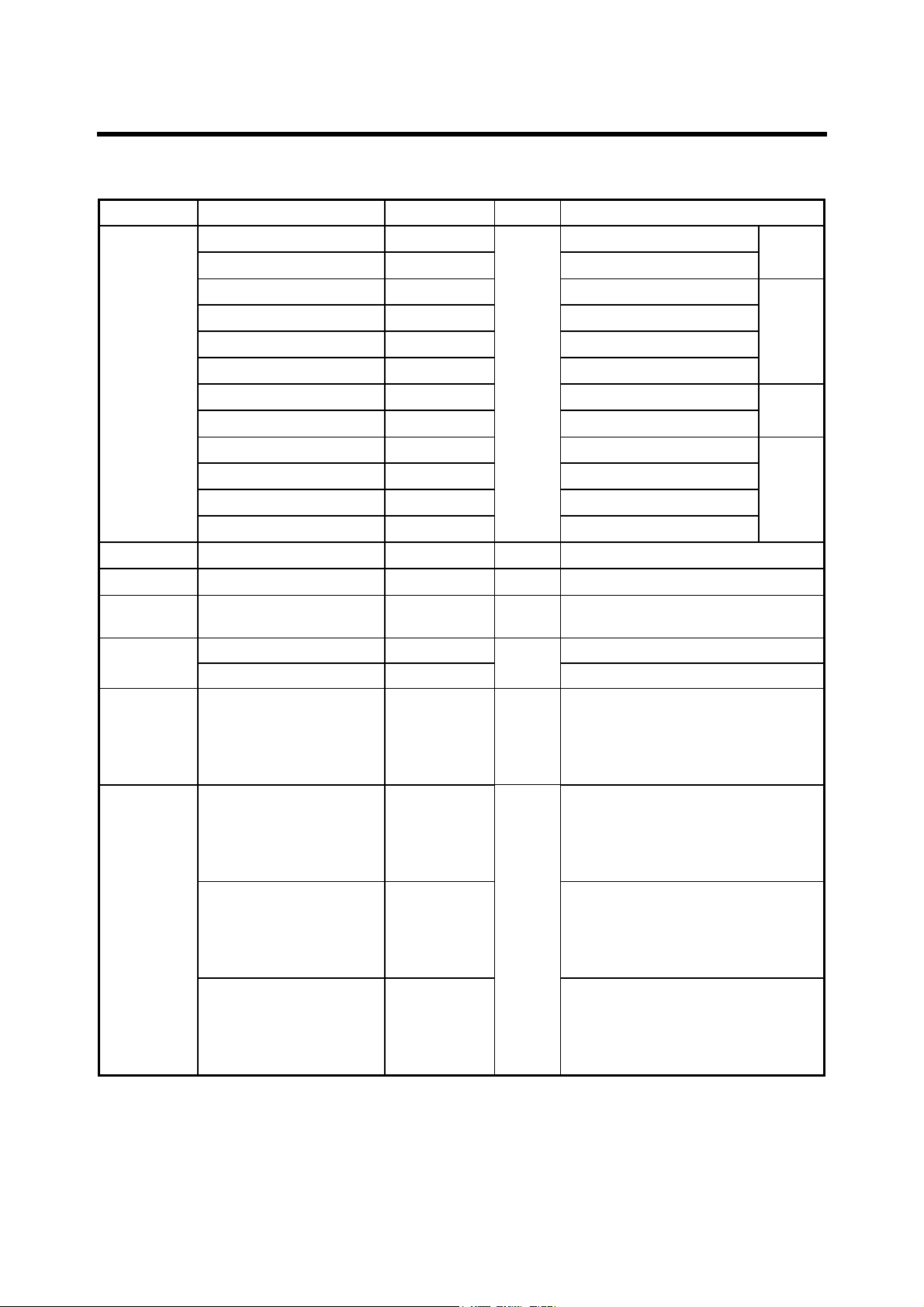
EQUIPMENT LISTS
Standard supply (System with monitor)
Name Type Code No. Qty Remarks
XN12AF-RSB-0074-062
XN12AF-RSB-0075-062
XN20AF-RSB-0074-062
XN20AF-RSB-0075-062
XN24AF-RSB-0074-062
Antenna
Unit
XN24AF-RSB-0075-062
XN12AF-RSB-0074-063
XN12AF-RSB-0075-063
XN20AF-RSB-0074-063
XN20AF-RSB-0075-063
XN24AF-RSB-0074-063
XN24AF-RSB-0075-063
Monitor RDP-124-M-ES
Control Unit RCU-011
Processor
Unit
RPU-011
−
−
−
−
−
−
−
−
−
−
−
−
−
−
−
SP03-12500 (DC mains) 000-089-390 SP03-12501, SP03-12505 Spare Parts
SP03-12510 (AC mains) 000-089-391
Accessories FP03-07410 000-089-584
CP03-20400 000-089-748 CP03-19105: Monitor
CP03-20410 000-089-749 CP03-19105: Monitor
Installation
Materials
CP03-20420 000-089-750
1 set
1 set
Select
one
FR-2115-B, 24 r pm, 1200 mm
FR-2115-B, 42 r pm, 1200 mm
FR-2115-B, 24 r pm, 2000 mm
FR-2115-B, 42 r pm, 2000 mm
FR-2115-B, 24 r pm, 2400 mm
FR-2115-B, 42 r pm, 2400 mm
1
FR-2125-B, 24 r pm, 1200 mm
FR-2125-B, 42 r pm, 1200 mm
FR-2125-B, 24 r pm, 2000 mm
FR-2125-B, 42 r pm, 2000 mm
FR-2125-B, 24 r pm, 2400 mm
FR-2125-B, 42 r pm, 2400 mm
1
1
1
SP03-12501, SP03-12506
FP03-07401: Accessories
FP03-06201: Handle
FP03-06502: Accessories
FP03-06503: Hood
Dust cover 03-144-1338
CP03-19104: Antenna Unit
Signal Cable: S03-75-15 (15 m)
Cable Assy: UL1007/2C-2V
(10 m), for monitor
CP03-19104: Antenna Unit
Signal Cable: S03-75-20 (20 m)
Cable Assy: UL1007/2C-2V
(10 m), for monitor
CP03-19105: Monitor
CP03-19104: Antenna Unit
Signal Cable: S03-75-30 (30 m)
Cable Assy: UL1007/2C-2V
(10 m), for monitor
CP03-
24201
CP03-
19101
CP03-
24201
CP03-
19101
iii
Page 6

Standard supply (System without monitor)
Name Type Code No. Qty Remarks
XN12AF-RSB-0074-062
XN12AF-RSB-0075-062
XN20AF-RSB-0074-062
XN20AF-RSB-0075-062
XN24AF-RSB-0074-062
Antenna
Unit
XN24AF-RSB-0075-062
XN12AF-RSB-0074-063
XN12AF-RSB-0075-063
XN20AF-RSB-0074-063
XN20AF-RSB-0075-063
XN24AF-RSB-0074-063
XN24AF-RSB-0075-063
Control Unit RCU-011
Processor
Unit
Spare Parts
RPU-011
SP03-12500 (DC mains) 000-089-390 1 SP03-12502, SP03-12505
−
−
−
−
−
−
−
−
−
−
−
−
−
−
SP03-12510 (AC mains) 000-089-391 SP03-12502, SP03-12506
Accessories FP03-07510 000-089-586 1 FP03-06502, FP03-07401
CP03-19100 000-089-393 CP03-19104: Antenna Unit
Installation
Materials
CP03-19110 000-089-394 CP03-19104: Antenna Unit
Select
one
CP03-19120 000-089-395
FR-2115-B, 24 r pm, 1200 mm
FR-2115-B, 42 r pm, 1200 mm
FR-2115-B, 24 r pm, 2000 mm
FR-2115-B, 42 r pm, 2000 mm
FR-2115-B, 24 r pm, 2400 mm
FR-2115-B, 42 r pm, 2400 mm
1
FR-2125-B, 24 r pm, 1200 mm
FR-2125-B, 42 r pm, 1200 mm
FR-2125-B, 24 r pm, 2000 mm
FR-2125-B, 42 r pm, 2000 mm
FR-2125-B, 24 r pm, 2400 mm
FR-2125-B, 42 r pm, 2400 mm
1
1
CP03-19105: Monitor
Signal Cable: S03-75-15 (15 m)
CP03-19105: Monitor
Signal Cable: S03-75-20 (20 m)
CP03-19104: Antenna Unit
CP03-19105: Monitor
Signal Cable: S03-75-30 (30 m)
CP03-
24201
CP03-
19101
CP03-
24201
CP03-
19101
iv
Page 7

Optional equipment
Name Type Code No Qty Remarks
Remote Display FMD-8010
GC-8-2 008-446-520 Separate order Gyro Converter
GC-8-1 008-446-270
Interswitch RJ-7
Interswitch RJ-8
Performance
Monitor
Transformer Unit
Rectifier RU-3424 000-030-497 1
ARPA
Video Plotter RP-26-Z-1E 008-492-520 1 Built in
Video Plotter RP-26-Z-2E 008-485-520 1 Separate order
Alarm Kit OP03-156 008-500-650 1
Performance
Monitor Inst. Kit
Power Cable
Conversion Kit
Interface Unit IF-2300
PM-30
RU-1758 000-030-416 1
RU-1803 000-030-420 1
ARP-26-1E 008-492-300 1 Built in
ARP-26-2E 008-485-500 1 Separate order
OP03-150 008-485-490 1
CVV-S
(8X2C)-15C
OP03-161-24 008-499-760 1 24 rpm antenna AC-DC
OP03-161-42 008-499-770 1 42 rpm antenna
000-560-634 1
−
−
−
−
−
1
1 set
Built in
1
1
1 Mandatory for IMO radar
1 Mandatory for IMO radar
v
Page 8
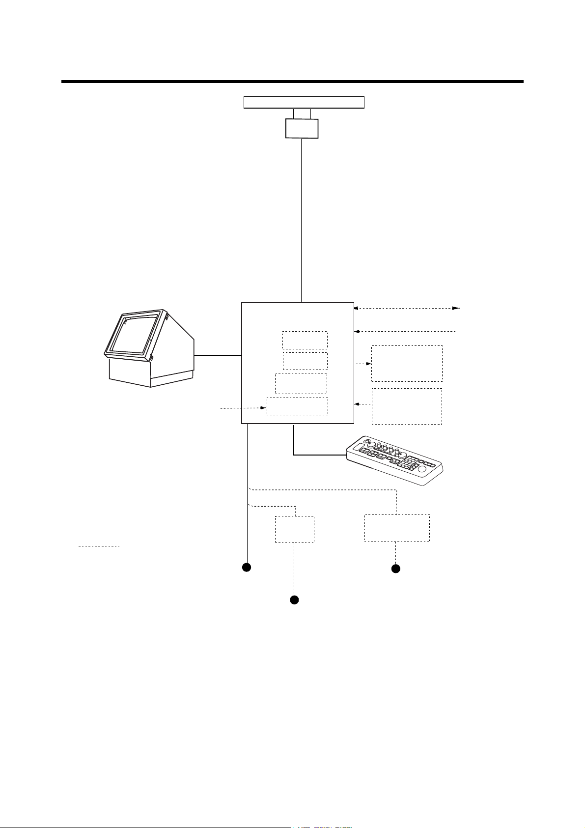
SYSTEM CONFIGURATION
ANTENNA UNIT
FR-2115-B: XN12AF-RSB-0074-062
XN12AF-RSB-0075-062
XN20AF-RSB-0074-062
XN20AF-RSB-0075-062
XN24AF-RSB-0074-062
XN24AF-RSB-0075-062
FR-2125-B: XN12AF-RSB-0074-063
XN12AF-RSB-0075-063
XN20AF-RSB-0074-063
XN20AF-RSB-0075-063
XN24AF-RSB-0074-063
XN24AF-RSB-0075-063
MONITOR
RDP-124-M-ES
Gyrocompass
AC spec or DC spec to be selected.
Option
PROCESSOR UNIT
RPU-11
Alarm Kit
OP03-156
ARPA Board
ARP-26
Video Plotter
RP-26
Gyro Converter
GC-8
DC spec
Rectifier
RU-3424
IEC 61162-1 (Input/Output)
IEC 61162-1 (Input)
Slave Display
FMD-8010
Performance
Monitor
PM-30
CONTROL UNIT
RCU-11
AC spec
Transformer Unit
RU-1803
Navigator
Speed Log
Ship's Mains
24/32 VDC
or
100/110/115/220/230 VAC
1
φ
, 50/60 Hz
440 VAC
1
φ
, 50/60 Hz
I/O Data Sentences
Input: GGA, RMA, RMB, RMC, GLL, ZDA, VBW, VHW, VTG, MWV, VWT, VWR, VDR, DPT,
DBT, DBS, MTW, BWR, BWC, WPT, RTE
Output: RAOSD, RARSD, RATTM
vi
Page 9

1. MOUNTING
1.1 Antenna Unit
1.1.1 Mounting considerations
• The antenna unit is generally installed either on top of the wheelhouse or on the radar mast,
on a suitable platform. Locate the antenna unit where there is a good all-round view.
• No funnel, mast or derrick should be within the vertical beamwidth of the antenna in the bow
direction, especially zero degrees ±5°, to prevent blind sectors and false echoes on the radar
picture.
• It is rarely possible to place the antenna unit where a completely clear view in all directions is
available. Thus, you should determine the angular width and relative bearing of any shadow
sectors for their influence on the radar at the first opportunity after fitting.
• Locate the antenna of a direction finder clear of the antenna unit to prevent interference to the
direction finder. A separation of more than two meters is recommended.
• To lessen the chance of picking up electrical interference, avoid where possible routing the
signal cable near other onboard electrical equipment. Also avoid running the cable in parallel
with power cables.
• A magnetic compass will be affected if placed too close to the antenna unit. Observe the
following compass safe distances to prevent deviation of a magnetic compass: Standard
compass, 1.70 m (FR-2115-B), 2.10 m (FR-2125-B), Steering compass, 0.90 m (FR-2115-B),
1.20 m (FR-2125-B).
• Do not paint the radiator aperture, to ensure proper emission of the radar waves.
• The signal cable run between the antenna and the display is available in lengths of 15 m
(standard), 20 m, and 30 m. Whatever length is used it must be unbroken; namely, no splicing
allowed.
• The antenna base is made of cast aluminum. To prevent electrolytic corrosion of the antenna
base, use the seal washers and corrosion-proof rubber mat.
• Deposits and fumes from a funnel or other exhaust vent can adversely affect the aerial
performance and hot gases may distort the radiator portion. The antenna unit must not be
mounted where the temperature is more than 70°C.
• Leave sufficient space around the unit for maintenance and servicing. See the antenna unit
outline drawing for recommended maintenance space.
1-1
Page 10
1.1.2 Assembling the antenna unit
The antenna unit consists of the antenna radiator and the antenna unit chassis, and they are
packed separately. Fasten the antenna radiator to the antenna unit chassis as follows:
1. For the XN20AF, XN24AF, attach two guide pins to the underside of the antenna radiator.
2. Remove the waveguide cap from the radiator bracket. The cap may be discarded.
3. Coat the waveguide flange with anticorrosive sealant as shown in Figure 1-1.
10 mm
Hole for
a guide pin
5 mm
O-ring
Hole for
a guide pin
Anticorrosive sealant
Figure 1-1 Coating the waveguide flange with anticorrosive sealant
4. Coat fixing holes for the antenna radiator with anticorrosive sealant.
5. Grease the O-ring and set it to the O-ring groove of the radiator flange.
6. Set the antenna radiator to the radiator bracket.
7. For the XN20AF, XN24AF, coat hex bolts (M8X40, slotted washer-head, 8 pcs.) with
anticorrosive sealant and use them to loosely fasten the antenna radiator to the antenna unit
chassis. For the XN12AF, coat hex bolts, flat washers and spring washers with anticorrosive
sealant and use them to loosely fasten the antenna radiator to the antenna unit chassis.
8. For the XN20AF, XN24AF, remove two guide pins (inserted at step 1).
9. Tighten the bolts loosely fastened at step 7.
CAUTION
Be sure to remove the guide pins.
Injury may result if the guide pins loosen
and fall.
1-2
Page 11
Antenna radiator
Figure 1-2 Fastening the radiator to the radiator bracket
Guide pin
(XN20AF,
XN24AF
only)
O-ring
Waveguide
Radiator bracket
Hex bolt (M8X40), 8 pcs.
(XN20AF, XN24AF only)
Hex bolt (M8X35), 8 pcs.
Flat washer
Spring washer
(XN12AF only)
1-3
Page 12
1.1.3 Fastening the antenna unit to the mounting platform
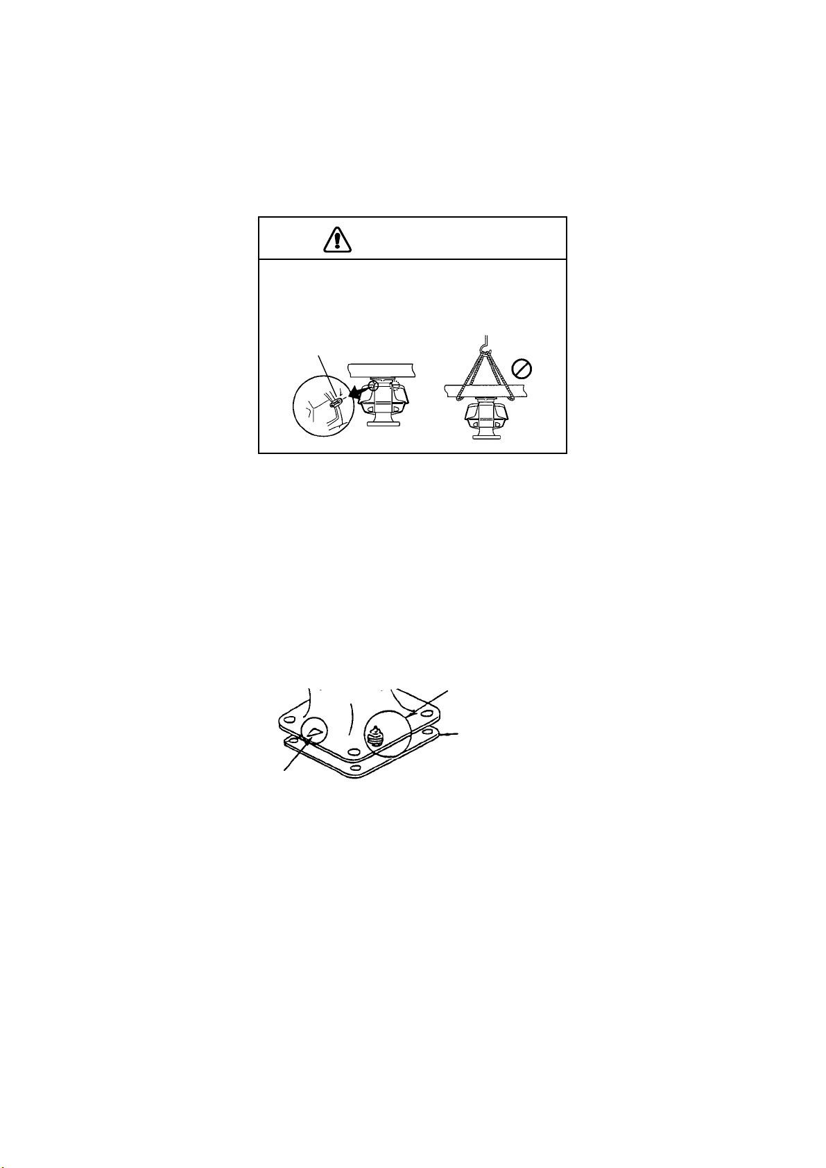
The antenna unit may be assembled before hoisting it to the mounting platform . However, do
not lift the antenna unit by the radiat or . Always hold the unit by its housing. When using a crane
or hoist, lift the unit by the hoist r ings which should be fastened to the bolt fixing covers of the
antenna housing.
CAUTION
DO NOT hoist the antenna unit by the
radiator; hoist it by the hoist rings. (Be sure to
remove rings after hoisting the antenna unit.)
Hoist
ring
1. Construct a suitable mount ing platform referring to the outline drawing at the back of the
manual.
2. Drill four m ount ing holes of 15 mm diameter and one cable entry hole of about 50 m m
diameter in the mounting platform.
3. Lay the rubber mat (supplied) on the mounting platform.
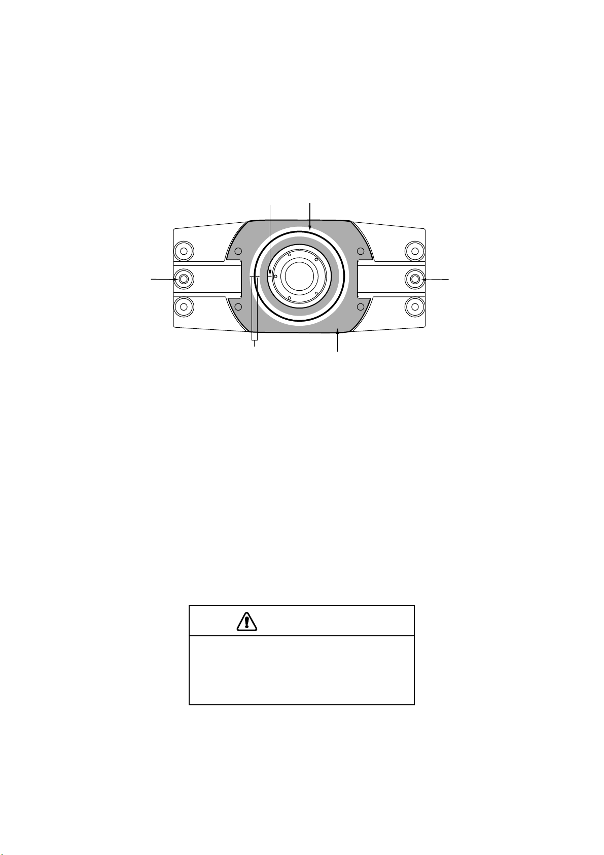
4. Place the antenna unit on the rubber mat orienting the unit so the bow mark on its base is
facing the ship's bow.
Ground terminal
Rubber mat
NO!
Bow mark
Figure 1-3 Antenna unit, front view
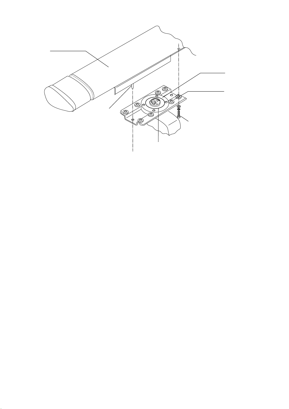
5. Fasten the antenna unit to t he mounting platform with four sets of M12X60 hex bolts, nuts,
flat washers and seal washers (supplied).
6. Using hex bolt (M6X25), nut (M6) and f lat washer (M6), establish t he ground system on the
mounting platform as shown in Figur e 1- 4. The location should be within 370 mm of the
ground terminal on the antenna unit. Connect the ground wire (RW-4747, 370 mm, supplied)
between the grounding point and ground ter minal on the antenna unit. Coat the entire
ground system with silicone sealant (supplied).
1-4
Page 13

CAUTION
Ground the equipment to
prevent electrical shock
and mutual interference.
Figure 1-4 How to mount the antenna unit
1-5
Page 14

1.2 Processor Unit
1.2.1 Mounting considerations
When selecting a mounting location, keep in mind the following points:
• The processor unit must be mounted horizontally.
• DO NOT place any item on the top of the processor unit.
• Locate the unit out of direct sunlight and away from heat sources because of heat that can
build up inside the cabinet.
• Locate the equipment away from places subject to water splash and rain.
• Be sure the mounting location is strong enough to support the weight of the unit under the
continued vibration which is normally experienced on the ship. If necessary reinforce the
mounting location.
• Determine the mounting location considering the length of the following cables:
a) Signal cable from the antenna unit
b) Power cable from the ship's mains
c) Monitor cable from the monitor
d) Control cable from the control unit
• Leave sufficient space on the sides and rear of the unit to facilitate maintenance. Also, leave a
foot or so of "service loop" in cables behind the unit for servicing ease.
• A magnetic will be adversely affected if placed too close to the processor unit. Observe the
following compass safety distances to prevent deviation of a magnetic compass: Standard
compass, 1.70 m, Steering compass, 0.90 m.
1-6
Page 15
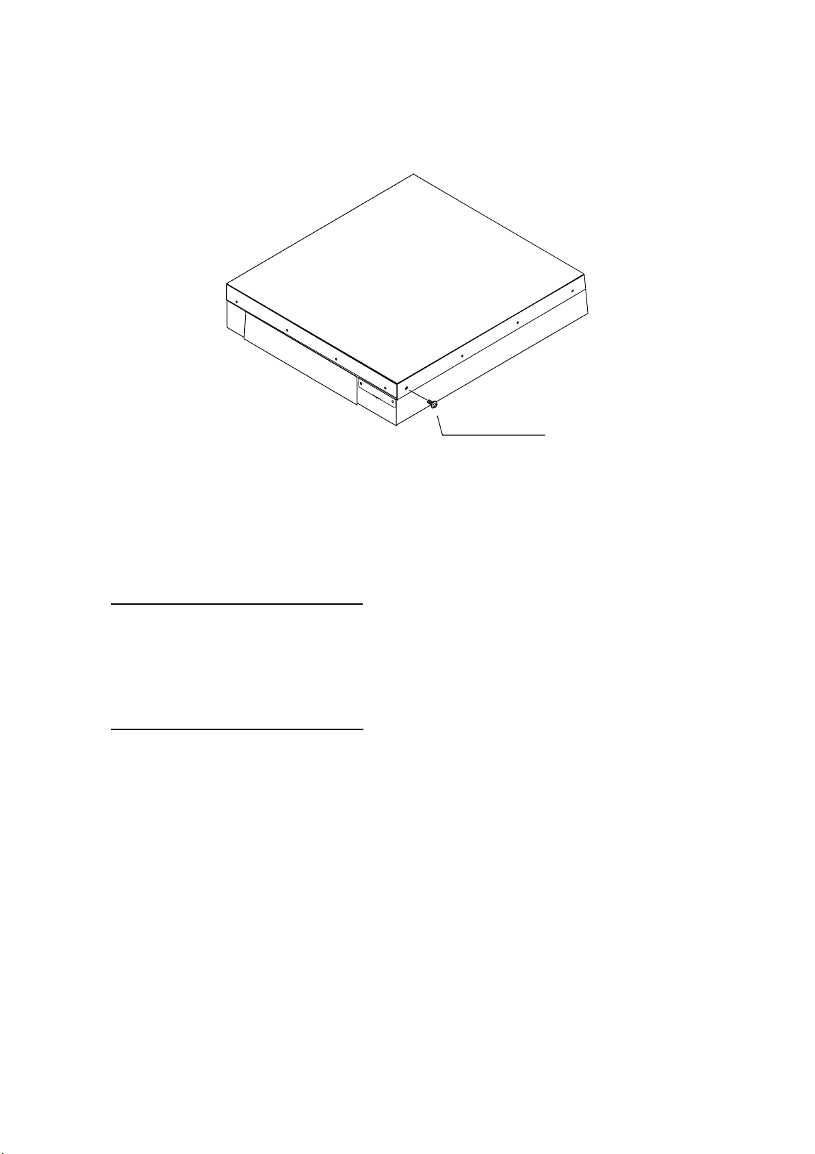
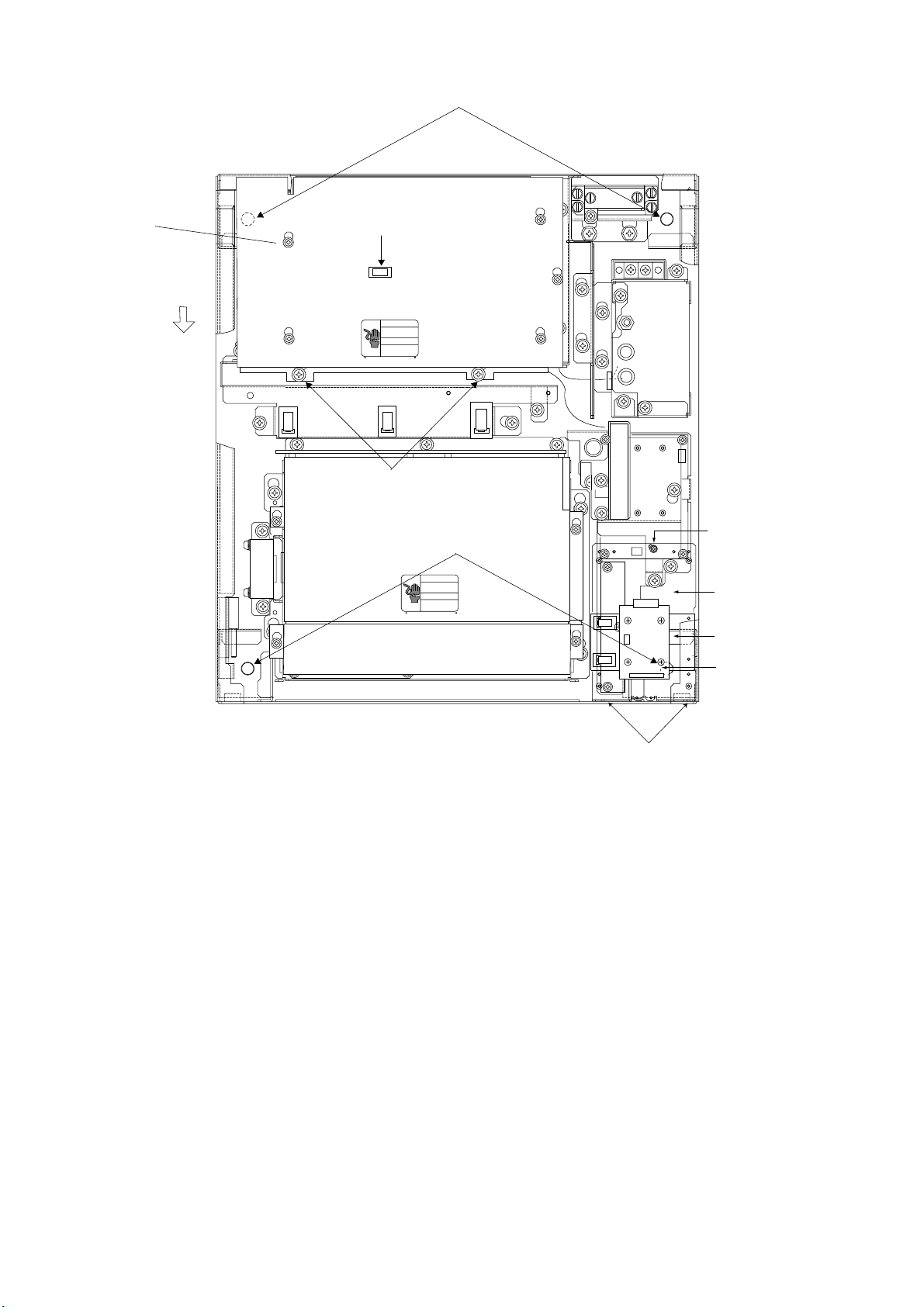
1.2.2 Mounting the processor unit
1. Drill four holes of 12 mm in diameter in the mounting location.
2. Unfasten 15 binding scr ews (M4) to remove the processor unit cover.
WARNING
Binding Screw
M4X8, 15 pcs.
Figure 1-5 Processor unit
3. Fasten the processor unit t o t he m ounting location with four each of M10 bolts, nuts and
washers, using the pipe box spanner (supplied). See the fig ure on the next page for location
of fixing holes.
How to access the rear-left fixing hole
The rear-left fixing hole is hidden under the PTU board cover. To access it do the following:
a) Loosen five M3X8 screws at the top of the PTU board cover and two M4X8 screws at the
front of the cover.
b) Grasp the knob on the cover and slide the cover toward the front of the unit to release it.
How to access the front-right fixing hole
The front-right fixing hole is hidden beneath the RGB Board. To access it do the following:
a) Unfasten the M4X8 pan-head screw from the RGB board mounting plate.
b) Unfasten two pan-head screws (M3X10) fixing the M-card cover.
4. After m ount ing the unit, fasten the PTU board cover and RGB board mounting plate, and
then close the processor unit.
1-7
Page 16
*Screw
(M3X8, 5 pcs.)
Slide forward.
J106
J105
J104
J103
Fixing hole (rear)
Knob
*
*
*
Screw (M4X8, 2 pcs.)
Fixing hole (front)
J446
J466
J462
J465
*
Pan-head
Screw M4X8
RP board
mounting plate
RGB board
mounting plate
RGB Board
Pan-head Screw
M3X10
Figure 1-6 Pr oc ess or unit, inside view
1-8
Page 17

1.3 Monitor
The FR-2115-B/2125-B is available with or without a monitor. This section shows how to mount
the monitor supplied.
Mounting considerations
• The monitor is designed to be mounted on a desktop.
• Locate the monitor where it can be easily operated while viewing the screen and operating the
control unit.
• DO NOT place the monitor on the top of the processor unit.
• Locate the monitor out of direct sunlight and away from heat sources because of heat that can
build up inside the cabinet.
• Locate the equipment away from places subject to water splash and rain.
• Be sure the mounting location is strong enough to support the weight of the unit under the
continued vibration which is normally experienced on the ship. If necessary reinforce the
mounting location.
• The length of the monitor cable which runs between the processor unit and the monitor is 10
m. Keep this distance in mind when selecting the mounting location for the monitor.
• Leave sufficient space on the sides and rear of the unit to facilitate maintenance.
1-9
Page 18
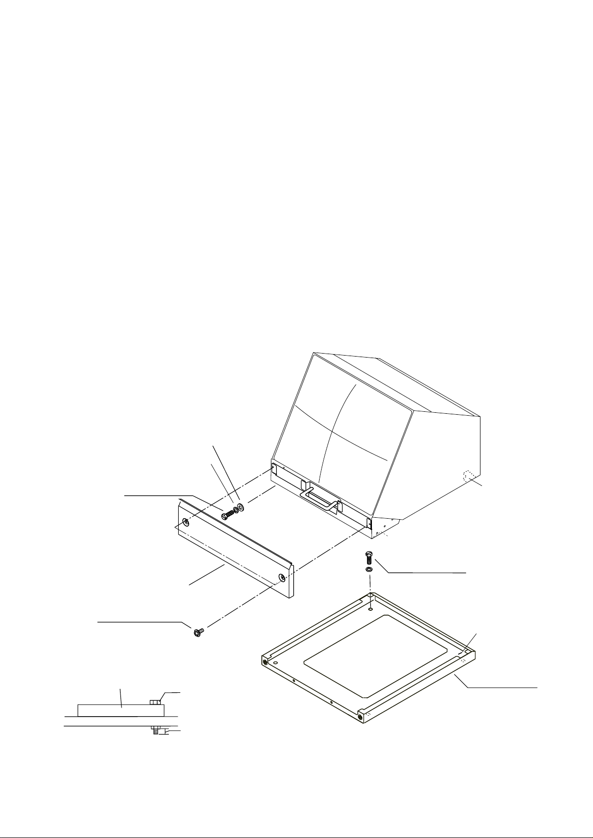
1.3.2 Mounting the monitor
1. Drill four holes of 12 mm in diameter in the mounting location, referring to the outline
drawing for mounting dimensions.
2. Unfasten two M4X10 screws to dismount the monitor cover.
3. Unfasten two sets of M10 bolts, plain washers and spring washers at the front of the monitor
to separate the monitor from the mounting base.
4. Pull the monitor forward about 4 centimeters and then lift if from the mounting base.
5. Fasten the mounting base to the mounting location with M10 bolts, nuts and washers (local
supply), using the pipe box wrench supplied. Make sure there is 3mm protrusion under the
nut.
6. Lay the monitor on the top of the mounting base, making sure the rear pin on the monitor is
mated with the slit in the mounting base. Fix the mounting base with the two sets of bolts,
and washers unfastened at step 3.
7. Fasten the monitor cover.
Plain Washer, M10, 2 pcs.
Spring Washer, M10, 2 pcs.
Hex Bolt
M10X30,
2 pcs.
Monitor Cover
Pan-Head Screw
M4X10, 2 pcs.
Mounting Base
Hex Bolt.
(M10)
Pin
Hex Bolt
M10, 4 pcs.
Washer
Slit
Mounting Base
More than 3mm
Figure 1-7 Monitor
1-10
Page 19
1.4 Control Unit
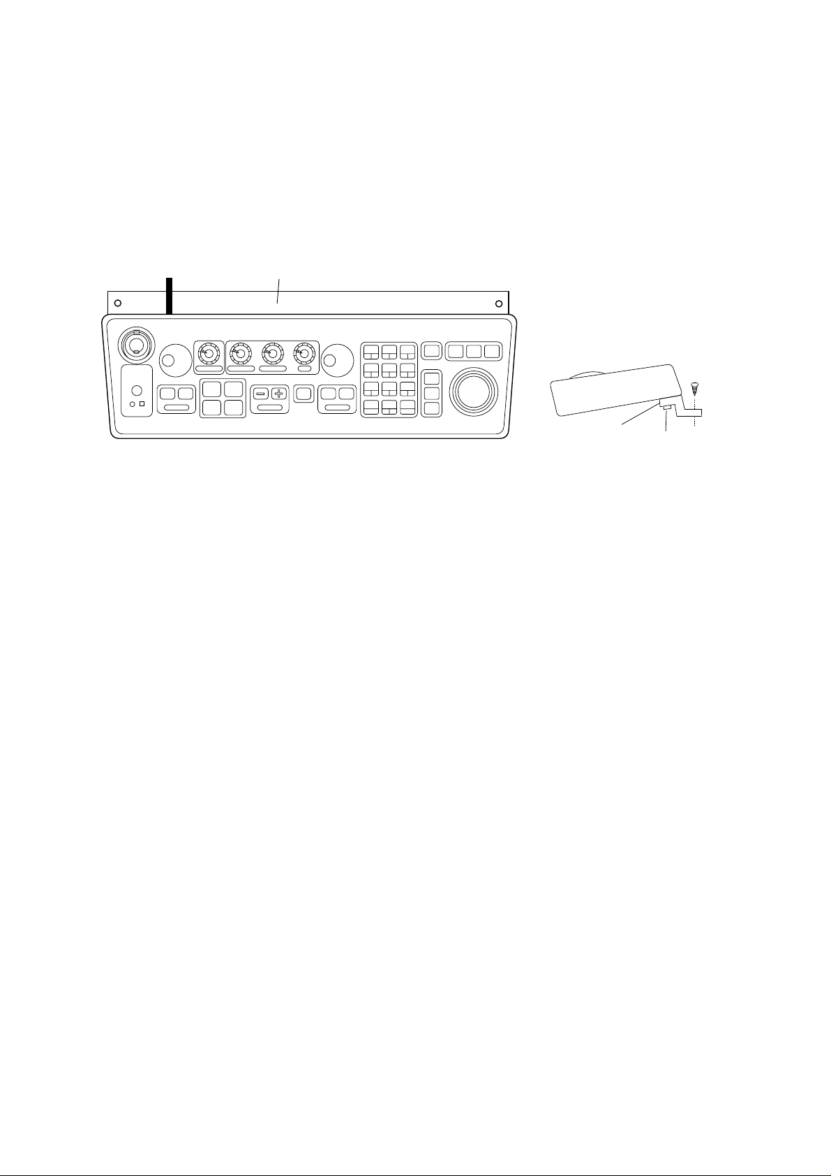
1.4.1 Mounting procedure
1. Attach rubber to feet to the bottom of the k eyboard if the keyboard is not going to be
permanently fixed. To fix the keyboard t o a desir ed locat ion, fasten the KB fixing plate to the
keyboard and desired location with two upset screws (M5X10, supplied) and two tapping
screws (φ6.5, local supply) as below.
KB Fixing Plate
Figure 1-8 How to attach KB fixing plate
2. Set KB dust cover (supplied) t o t he control unit.
CONTROL UNIT
SIDE VIEW
KB Fixing
Plate
φ6.5
Tapping
Screw
M5X10
Upset
Screw
1-11
Page 20
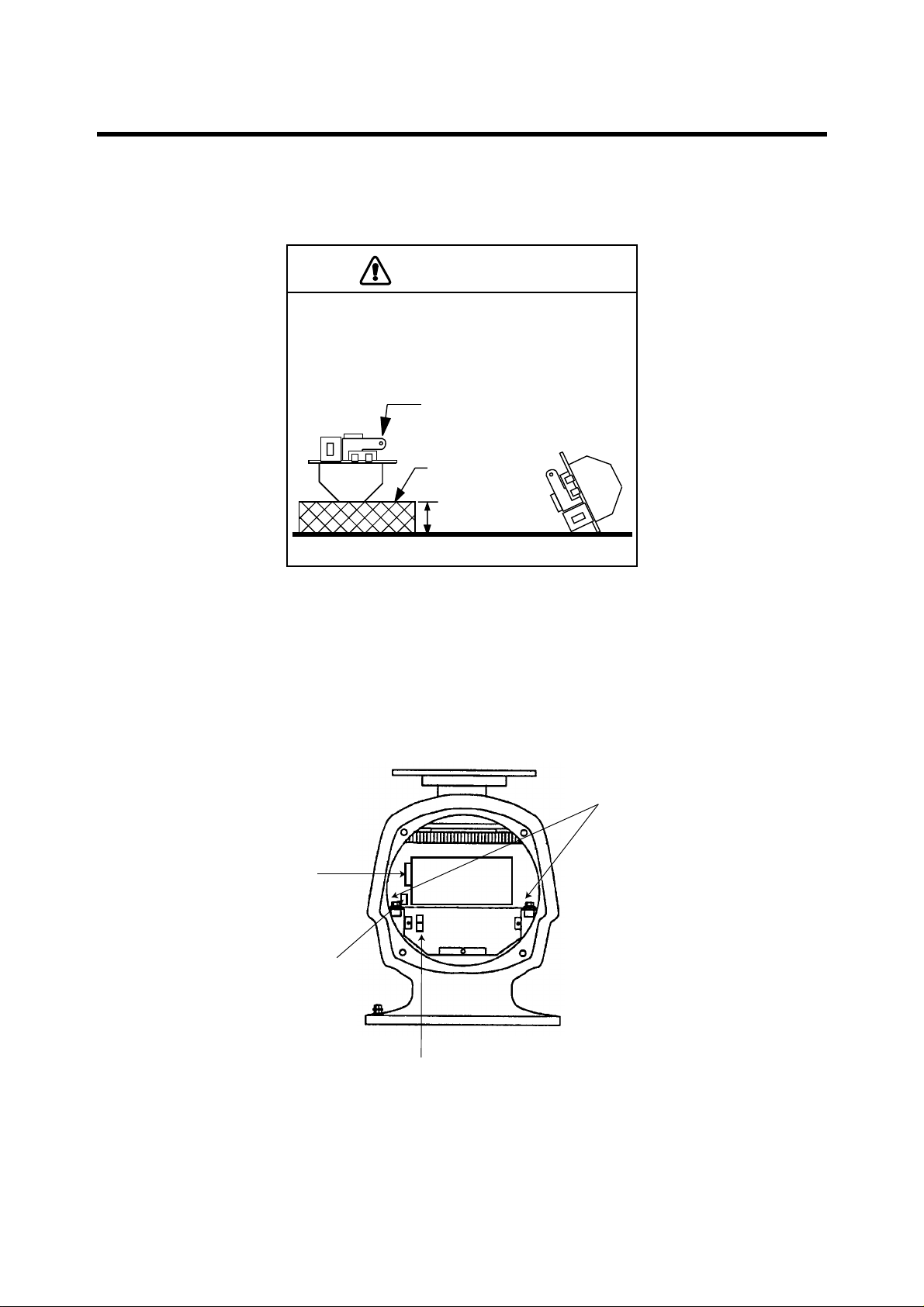
2.1 Antenna Unit
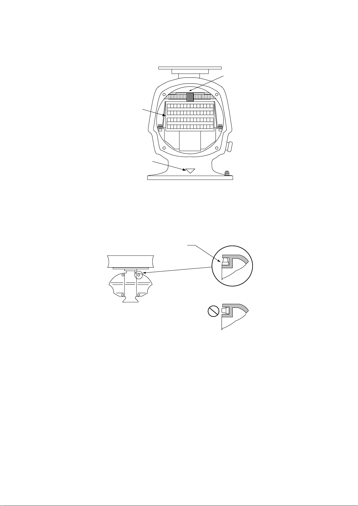
The magnetron in the transceiver module will demagnetize if it contacts ferrous material. When
dismounting the transceiver module, lay it on its
side or on top of non-ferrous material as shown
below.
2. WIRING
CAUTION
Transceiver module
(magnetron inside)
Non-ferrous
block
Height more
than 5 cm
2.1.1 Mounting the antenna chassis
1. Open the antenna unit cover.
2. Disconnect plugs P611, P801 and P821 from the antenna unit.
3. Unfasten two bolts to dismount the transceiver module.
J611
J801
Fixing
bolts
J821
Figure 2-1 Antenna unit, front view
2-1
Page 21
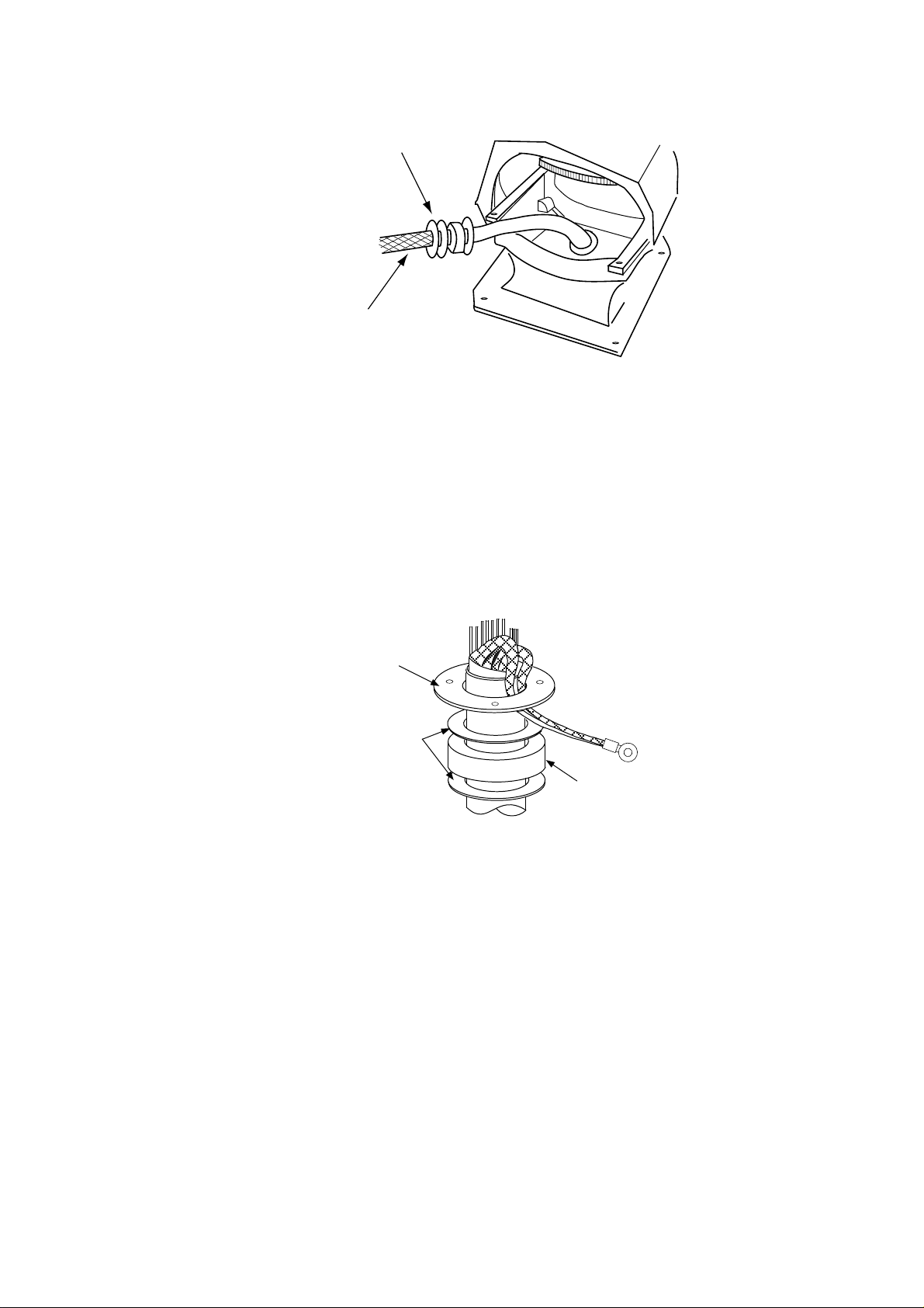
4.
Unfasten the four fixing bolts on the cable gland at the base of the antenna unit. Remove
clamping ring, rubber gasket and washers.
From left: Clamping ring,
washer, rubber gasket
and washer
Signal cable
Figure 2-2 Antenna unit, front view, cover removed
5. Pass the signal cable through the cable entry hole in the antenna unit mounting platf o rm.
Trim the cable so about 80 cm of it protrudes past the cable gland.
6. Slide the clamping ring, washer, rubber gasket and washer onto the cable in that order.
7. Fabricate the signal cable as shown on page 2-4.
8. Referring to Figure 2-3, pass the outer and inner shields between the signal cable and the
clamping ring. Fasten the cable gland.
Clamping
ring
Washers
Rubber
gasket
Figure 2-3 Passing cable shields between cable and clamping ring
9. Connect the signal cable to the terminal board RTB801 by referring to the interconnection
diagram. Leave slack in the coaxial wire to prevent breakage.
10. Bind cores of cables with cable ties.
11. Mount the transceiver module. Connect plugs P611, P801 and P821. Fasten the shield to
the ground terminal on the transceiver module.
2-2
Page 22
12. If the antenna is mounted 2° or more left of ship's bow, adjust the position of S901 so it
becomes "on" (contact between #1 and #2 on pcb MP-3795). To access S901, open the
bow side cover; S901 is above the drive gear.
S901
RTB801
Bow mark
1 2 345 6 7891011121314
15 16 171819 20 212223 2425 26 2728
Figure 2-4 Antenna unit, front view
13. Confirm that all screws are tightened and all wiring is properly made. Coat waterproofing
gasket, bolts and tapping holes of antenna unit with silicone grease. Check that the
waterproofing gasket is seated as shown in Figure 2-5. Close the antenna unit cover.
Coat gasket with silicone grease.
DO NOT use silicone sealant.
CORRECT
WRONG
Figure 2-5 Correct seating of waterproofing gasket
2-3
Page 23
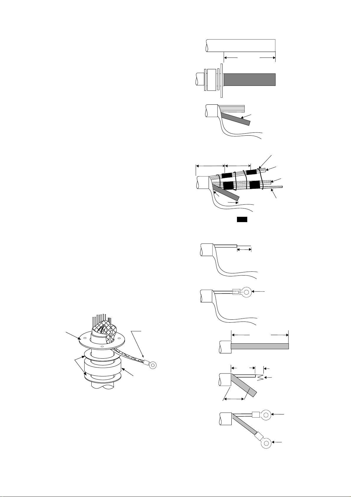
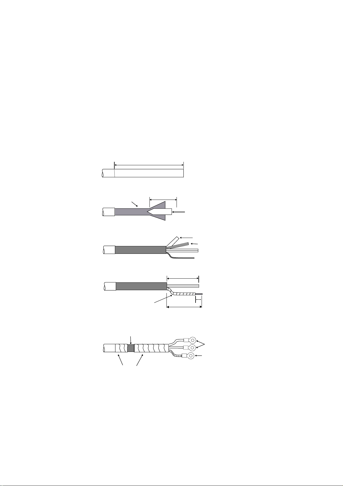
2.1.2 Fabricating signal cable S03-75
1. Remove the vinyl sheath by 450 mm.
2. Slide the clamping ring, washer, rubber gasket
and washer onto the signal cable in that order.
3. Unravel the outer shield to expose the cores in
the outer layer. Then, unravel the inner shield to
expose the cores in the inner layer. Label all
inner cores to aid in identification.
4. Attach EMI cores to all inner cores and all outer
cores, and bind them with cable ties, etc. Note
that there are two types of the EMI cores, thick
and thin.
5. Trim each core (except coaxial wire) considering
its location on the terminal board in the antenna
unit.
6. Trim the inner and outer shields leaving 500 mm
each. Twist shields together and attach crimp-on
lug FV5.5-4 (blue, φ4).
Under
100 mm
VINYL SHEATH
450 mm
70-130 mm
500mm
Inner shield
Cable tie
Outer cores
Inner cores
Coax cable
= EMI cores
Outer cores: RFC-13 (thick)
Inner cores: RFC-10 (thin)
7. Remove insulation of each core by about 6 mm.
Fix crimp-on lug FV1.25-3 (red, φ3) to each core.
8. Fabricate the coaxial cable. Make the length 10
mm longer than the shield to prevent wire strain.
Attach crimp-on lug FVD1.25-3 (red, φ3) to
coaxial cable.
Clamping
ring
Washers
Crimp-on lug
FV5.5-5
(Blue, φ4)
Rubber
gasket
Figure 2-7 Ho w to ground
signal cable S03-75
Figure 2-6 How to fabricate
signal cable S03-75
2C-2V
50 mm
45 mm
6 mm
Crimp-on lug
FV1.25-M3
(Red, φ3)
75 mm
6 mm
Fold four times
Cut here
Crimp-on lug
FVD1.25-3
(Red, φ3)
Crimp-on lug
FV1.25-3
(Red, φ3)
2-4
Page 24
2.2 Processor Unit
Two cables are terminated at the processor unit: the signal cable S03-75 and the power cable.
The signal cable comes with a connector preattached to it for connection to the processor unit.
Fabricate the power cable as below.
2.2.1 Fabricating the AC power cable
1. Remove the vinyl sheath by 80 mm. Cut off jute tape wrapped around the armor. Unravel
the armor to expose the cores by about 35 mm.
2. Remove insulation of cores by about 10 mm. Fix crimp-on lugs to the cores and armor.
3. Cover the armor with vinyl tape, leaving the portion which will lie inside the cable clamp
untaped.
Vinyl sheath
Core
S = 3.5 mm
φ = 2.4 mm
(a)
(b)
(c)
(d)
DPYCY-3.5
Approx. 80 mm
40 mm
Clamp here.
2
5 mm
Armor
Taping
10 mm
Armor
Vinyl sheath
(sectional view)
Figure 2-8 Fabricating power cable DPYCY-3.5
2-5
Page 25
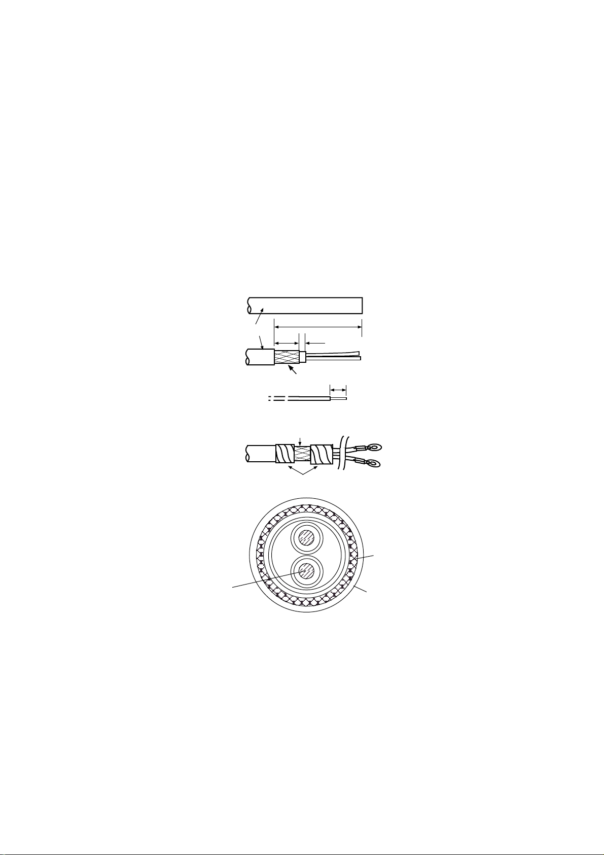
2.2.2 Fabricating the DC power cable (CVV-S 8X2C, option)
1. Remove the vinyl sheath by 100 mm.
2. Unravel the braided shield 60 mm from end of cable.
3. Remove the jute tape and inclusion from cable.
4. Expose the cores by 50 mm.
5. Expose the shield by 60 mm. Tape the shield, leaving 10 mm exposed.
6. Remove the sheath of cores by 10 mm. Attach crimp-on lug type 8NK4 to the cores and
crimp-on lug type FV5.5-4 (yellow) to the shield.
7. Tape the cable as shown in the figure below. Fasten the shield to screw (M4) on the cable
clamp.
100 mm
CVV-S 8X2C
Braided Shield
Taping
Fasten cable
clamp here.
Taping
60 mm
Core
Jute Tape
Inclusion
50 mm
10 mm
60 mm
Crimp-on Lug
8NK4
Crimp-on Lug
FV5.5-4
Figure 2-9 Fabricating power cable CVV-S 8X2C
2-6
Page 26
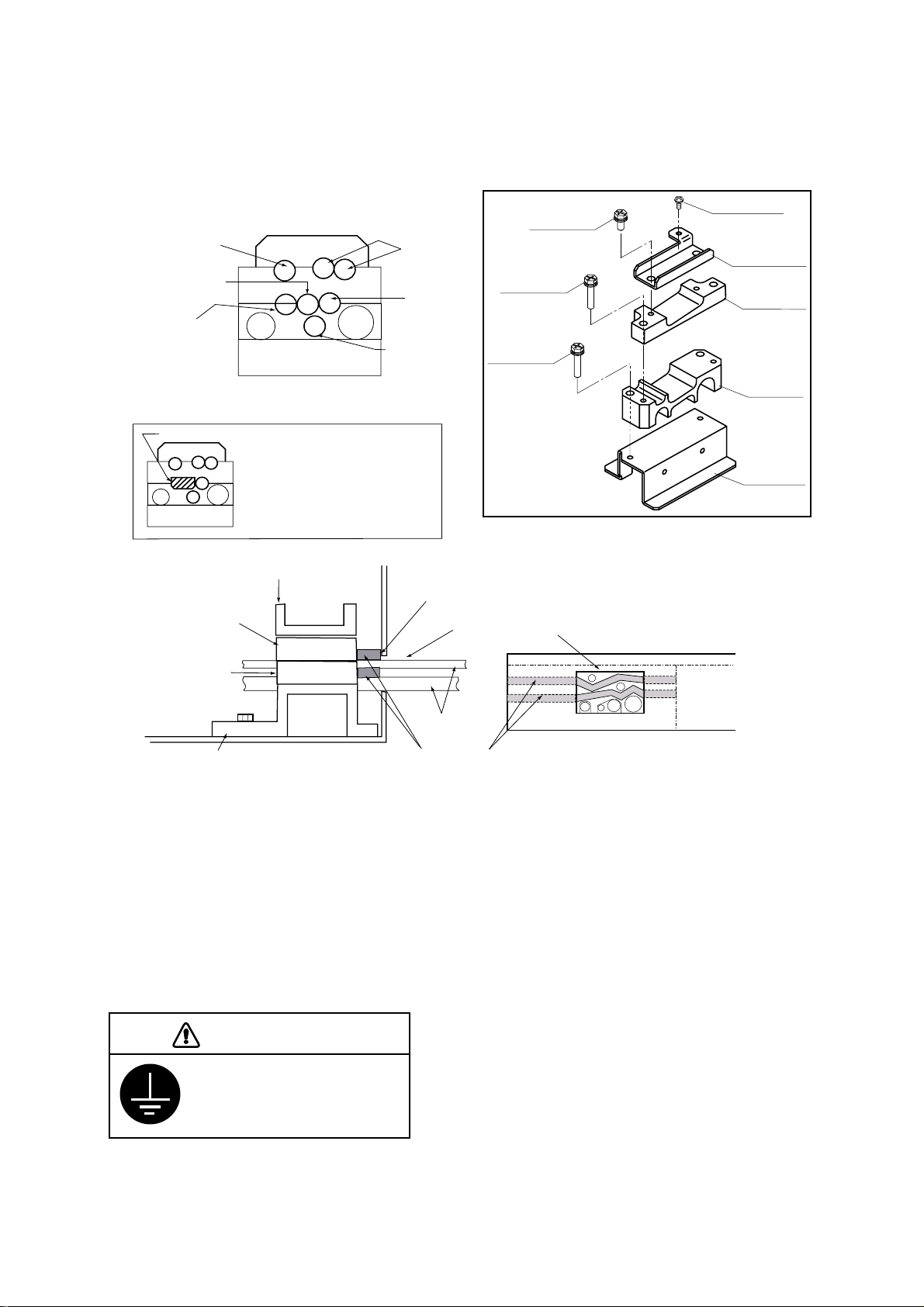
2.2.3 Leading in cables to the processor unit
Cables are led in to the processor unit through the cable clamp at the rear of the unit. Use the
shielding foam (supplied) as below to protect against noise radiation.
Pan-head screw
M4X8
(D) Rear clamp
plate
(C) Signal clamp
(Aluminum)
(B) Power clamp
(Aluminum)
(A) Rear clamp
base
Nav equipment
(Gyro, etc.)
Navigator*
Log*
Rubber plug
PWR
Cable position in cable clamp
(Processor unit, rear view)
* When no log or nav equipment is
installed, insert rubber plug
(supplied) to the left of keyboard
cable to hold the cable in place.
ANT
Slave display
Control
unit
Monitor
Hex bolt
M5X12 SUS
2 pcs
Hex bolt
M5X35 SUS
2 pcs
Hex bolt
M5X35 SUS
2 pcs
(Construction of
cable clamp)
(D) Rear clamp plate
Make sure shielding foam contacts rear chassis.
(C) Signal cable
Rear cable entrance
(Aluminum)
(B) Power clamp
(Aluminum)
Cable
(A) Rear clamp base
(Processor unit, right-hand side view)
Shielding foam
(Processor unit, rear view)
Figure 2-10 Cable clamp position
•
Place shielding foam between cables, and then attach foam to aluminum clamps.
•
Fill unused clamp holes with shielding foam.
•
Connect a ground wire between the earth terminal on the processor unit and ship's
superstructure.
CAUTION
Ground the equipment to
prevent electrical shock
and mutual interference.
2-7
Page 27
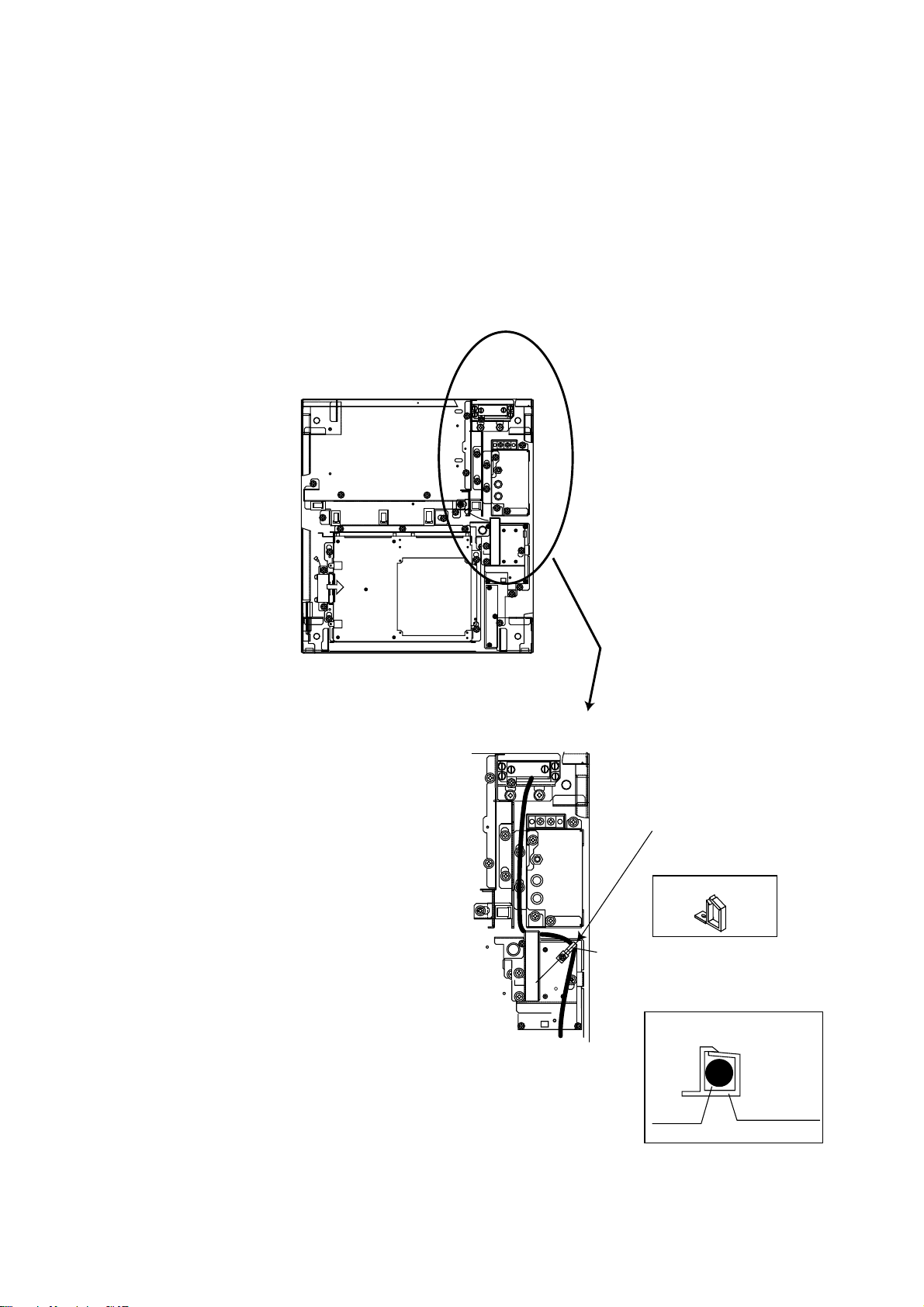
2.3 Monitor
2.3.1 Connection of monitor cable inside processor unit
The monitor cable (a monitor cable comes with FURUNO-supplied monitor) runs between the
RGB Board (inside the processor unit) and the monitor. Route it inside the processor unit as
below. Connect the cable to J2 on the RGB Board. If a converter adaptor is used it may be
necessary to route the cable differently than shown. In any case be sure the cable does not
touch the TX-HV Board.
EXPLODED VIEW
45°
TX-HV Board
(Underneath the plate)
Locking Wire Saddle
Locking Wire Saddle LWS-2H
with M3X10 Pan-head Screw
Cable inside Locking Wire
Saddle
Locking Wire
Cable
Saddle
Figure 2-11 Processor unit, inside view
2-8
Page 28

2.3.2 Connection of monitor cable inside the monitor
Connect the monitor cable inside the monitor as below.
MONITOR
REAR
VIEW
1
2
Connect to
CONNECTOR Board.
NH5P to J575
NH6P to J577
NH3P to J579
VH3P to J576
3
Cable Cover
Loosen two M4X10
pan-head screws.
Cable Entrance Plate
Unfasten three MX10
screws to remove cable
entrance plate.
Connect D-SUB
connector to J560
on the INTERFACE
Board.
Fasten ground wire with
M4X10 pan-head screw.
Unfasten top or bottom M4X10
pan-head screw fixing clamp plate.
Lay cable in clamp and then close
clamp plate.
MONITOR CABLE
4
5
Earth Terminal
Clamp Plate
CONNECTOR Board
INTERFACE Board
Fasten D-SUB connector
with screw.
1. Fasten cable
entrance
plate.
2. Close cable
cover.
3. Fasten ground
wire between
earth terminal
and ship's
superstructure.
CAUTION
Ground the equipment
to prevent electrical
shock and mutual
interference.
Figure 2-12 Connection of monitor
2-9
Page 29

2.4 Control Unit
1. Open the processor unit.
2. Lead in the control unit cable assy. (option) from the rear entrance of the processor unit.
3. Inside the processor unit, fasten ground the wire of the cable assembly with an M4 screw on
the chassis.
4. Plug in two connectors of control unit cable to P412 and J583.
P412
PTU COVER
Control Unit
Cable
Earth Wire
J583
MB 03P9251
INT 03P9252
Figure 2-13 Processor unit, inside view
2-10
Page 30

2.5 External Equipment
Open the processor unit. Remove the cover from the INT Board. Connect signal, power (ship's
mains and power supply), gyro, log and monitor cables as below. Optional equipment are
connected to the INT Board - see the next page for information.
Nav equipment
(Gyro, etc.)
Navigator
Log
CABLE POSITION IN CABLE CLAMP (front view)
J442
J443
J444
J463
PWR
PTU BOARD 03P9245
(behind cover)
MOTHER BOARD 03P9251
J457
J450
J454
J458
J455
J466
J453
J451
J462
J456
J452
INT BOARD 03P9252
Plug in coaxial
cable here.
J445
J448
J446
J449
J467
J465
Slave display
Control
ANT
unit
Monitor
J5
J4
GYRO CONVERTER
BOARD 03P9252
DJ1
Antenna
Gyro
Monitor
Log
Ship's mains
TB1
Ground terminal
POWER switch
(AC spec. only)
Normally ON
Fasten TX-HV line
to #1 terminal.
To fasten;
1. Unfasten screws.
2. Slide terminal forward.
3. Lift terminal to
remove it.
M4X8 (2 pcs.)
Connect cables
to terminal board
referring to inter-
connection diagram.
3
2
1
2
3
4
5
6
7
8
Fasten antenna cable to DJ1
with M3X8 screw (2 pcs., supplied).
Figure 2-14 Processor unit, inside view
2-11
Page 31

Connectors on the INT Board
Table 2-1 Connectors on the INT Board
Signal
Name
INPUT SIGNAL
signal
Speed log
signal
Radar buoy
signal
Remote
display
signal
OUTPUT SIGNAL
External
ARPA
signal
Slave display
signal
Name on
PCB
LOG J448 NH, 3 pin
RADAR
BUOY
EXT-RADAR
or RJ-7
EXT-ARPA J444 NH, 8 pin
SLAVE J442
Connector
No.
J4 VH, 3 pinGyro
J5 VH, 5 pin
J445 NH, 4 pin
J458 NH, 8 pin
J443
Connector
Type
NH, 8 pin CD-140,
Applicable
Equipment
CD-141,
GD-500,
GD-500MK2,
FMD-800,
FMD-8010 *1
Remarks
On pcb
A64P1106
(option)
200 pulses/nm,
etc.
Heading,
bearing,
Tx trigger
Heading,
bearing, video,
Tx trigger
*1 Monitor for
FR-2115-B/2125-B
can be used as
slave display unit.
Buzzer signal EXT-BUZ J451 NH, 9 pin Speaker w/amp Speaker signal
Monitor signal J449 NH, 10 pin
RS-232C RS-232C J456 XH, 4 pin
Analog ANALOG J453 NH, 3 pin
External
buzzer
INPUT/OUTPUT SIGNAL
INS Data INS. DATA J455 NH, 5 pin
RJ-7 RJ-7 J457 NH, 15 pin
RJ-8 RJ-8 J416 NH, 4 pin On Mother
Nav data NAV DATA J450 NH, 5 pin
ARPA data ARPA DATA J454 NH, 5 pin
PM_ON_OFF PM_PRINT J411 XH, 3 pin
EXT ALARM
(AC)
J452 NH, 3 pin
VER synchronous,
HOR synchronous,
video
Board 03P9251
On Mother
Board 03P9251
2-12
Page 32

How to attach NH connector
HOW TO ATTACH NH CONNECTOR TO SIGNAL CABLE
NH connector wire
NH connector
housing
1) Insert NH connector
wire into NH connector
housing.
Shrink tubing
20mm
2) Cut shrink tubing
in 20 mm lengths and
slip onto each wire.
Solder
3) Solder connector
to signal cable.
4) Heat shrink
tubing with soldering iron.
Figure 2-15 How to attach NH connector
2.6 AC Power Specificati on of Processor Unit
For 100 VAC or 220 VAC power, add or delete jumper wires on the PTU Board and change the
power fuses inside the processor unit as shown in the table below according to ship's mains.
The figure below shows the location of the power fuses and the jum per wi res on the PT U Board.
Table 2-2 Jumper w ire setting on the PTU board, fuse rating and power specification
PCB
Power Spec.
(VAC)
Antenna
rpm
JP1 JP2 JP3 JP4 JP91 JP92
Power
Fuse
03P9245A 100/110/115 24 rpm YES YES YES NO NO NO 10A
03P9245D 220/230 24 rpm NO NO NO YES NO NO 5A
Jumper wire to use:
PTU Board
JP1: 0.8 dia. gilded wire
JP2, JP3, JP4, JP91, JP92: type ERD-S2TCOV
JP1
Fuse
JP2
JP92
JP3
JP4
03P9245
PTU Board
JP91
Figure 2-16 Processor unit, inside view
2-13
Page 33

3. INITIALIZATION AND ADJUSTMENT
3.1 Tuning Initialization
Tune the radar as follows: Press [RADAR MENU] [0] [0] [2] [0] [0] [0] [0] (TUNE INITIALIZE on
RADAR 3 menu) and press the [ENT] key. Also, confirm that "2.MODEL" is set to "FR-2115,
2125" on the INITIAL SETTING 4 menu, following paragraph 3.2 and then pressing [RADAR
MENU], [0], [0], [0], [2], [0], [0], [0]. Trouble may result if the setting is wrong.
3.2 Accessing Menus for Initialization and Adjustment
1. Turn on the power.
2. Press the [RADAR MENU] key five times while pressing and holding down the [HL OFF]
key.
3.2.1 Restoring default settings
1. Press [RADAR MENU] [0] [0] [0] [2] [0] [0] [0] to display the INITIAL SETTING 4 menu.
2. Press the [0] ke y to select FACTORY DEFAULT.
3. Press the [ENTER] key five times, and turn the power off and on again.
4. “Initializing” appears during restoring. It takes about 90 seconds to restore the default
sett ing s , aft e r wh ich th e no rm a l dis p la y appea r s. Confirm that "2. MODE L " is se t to " FR- 21 15,
2125" on the INITIAL SETTING 4 menu.
3.3 Adjusting Video Signal Level
When the signal cable is very long, the video amplifier input level decreases, shrinking target
echoes. To prevent this, confirm (and adjust if necessary) video amplifier input level.
1. Connect an oscilloscope to TP6 on the INT Board (03P9252) in the processor unit.
2. Transmit on the 12 nm range.
3. Adjust R21 on the INT Board so the val ue of TP6 i s 4 Vpp. ( F or rem ote di s play , adj ust R 134
on the INT Board.)
TP1
INT Board
(03P9252)
R134
TP6
R21
Figure 3-1 Pr oc ess or unit, cov er opened
3-1
Page 34

3.4 Heading Alignment
You have mounted the antenna unit faci ng str ai ght ahead i n the di r ecti on of the bow . T her efore,
a small but conspicuous target dead ahead visually should appear on the heading line (zero
degrees).
In practice, you will probably observe some small bearing error on the display because of the
difficulty in achieving accurate initial positioning of the antenna unit. The following adjustment
will compensate for this error.
Correct bearing
relative to heading
Target
a
270
Scanner mounted
error to port
(HDG SW advanced)
000
010
350
020
340
330
320
310
300
290
280
260
250
240
230
220
210
200
030
040
140
150
160
190
170
180
Picture appears
deviated clockwise.
a
050
060
070
080
090
100
110
120
130
Apparent
position
of target
Scanner mounted
error to starboard
(HDG SW delayed)
Apparent position
of target
Target
b
b
000
010
350
020
340
330
320
310
300
290
280
270
260
250
240
230
220
210
200
030
040
050
060
070
080
090
Correct
100
110
bearing
120
130
relative to
140
150
160
190
170
180
heading
Picture appears
deviated counterclockwise.
Figure 3-2 Heading alignment
1. Turn on the power. Press [RADAR MENU] [0] [0] [0] [2] [2] to select HL ALIGN on the
INITIAL SETTING1 menu.
2. Select a target echo (by gy roc om pass , for exam pl e) at a r ange betw een 0.125 and 0.25 nm ,
preferably near the heading line.
3. Operate the EBL control to bisect the target echo with the heading line. (The value shown
on the display is scanner position in relation to ship's bow.)
4. Press [ENTER] to finish.
3-2
Page 35

3.5 Adjusting Sweep Timing
Sweep timing di ffers wi th r espec t to the length of the si gnal c abl e between the antenna uni t and
the processor unit. Adjust sweep timing at installation to prevent the following symptoms:
The echo of a "straigh t" target (for example, pier), on the 0.25 nm range , will appear on the
•
display as being pulled inward or pushed outward. See Figure 3-3.
The range of target echoes will also be incorrectly sho wn.
•
(1) Correct
(2) T arget pushed
inward
(3) T arget pushed
outward
Figure 3-3 Examples of correct and i nc or r ec t sweep timings
1. Turn on the power. Press [RADAR MENU] [0] [0] [0] [2] [3] to select TIMING ADJ on the
INITIAL SETTING1 menu.
2. Transmit on the 0.25 nm range.
3. Adjust radar picture controls to display picture properly.
4. Select a target echo which should be displayed straightly.
5. Adjust the VRM control to straighten the target echo.
6. Press [ENTER].
3.6 Suppressing Main Bang
If main bang appears at the screen center, suppress it as follows:
1. Turn on the power. Transmit on a long range and then wait ten minutes.
2. Adjust [GAIN] control to show a slight amount of noise on the display.
3. Select the 0.25 nm range. Adjust the [A/C SEA] control to suppress sea clutter.
4. Press [RADAR MENU] [0] [0] [0] [2] to open the INITIAL SETTING1 menu.
5. Press [7] to select 7. MBS.
6. Adjust the VRM control to adjust timing; the EBL control to adjust level.
7. Press [ENTER].
3-3
Page 36

3.7 Confirming Magnetr on Heater Voltage
Magnetron heater voltage is adjusted at the factory. However, confirm that it is within the
prescribed rating.
Table 3-1 Magnet r on heater voltage rating
Rating FR-2115-B (12 kW) FR-2125-B (25 kW)
ST-BY, 0.125 nm 7.4 to 7.6 V 8.2 to 8.4 V
TX, max range 7.4 to 7.6 V 6.5 to 7.5 V
1. Press [RADAR MENU] [0] [0] [0] [2] [0] to open the INITIAL SETTING2 menu.
2. Press [5] to select both the 5. SCANNER STOPPED field and the TX option and press
[ENTER]. Disconnect connector P821 from the antenna unit.
3. Turn off screen brilliance.
4. Measure voltage between pins #12(+) and #5(-) on connector P801 on the RFC Board
(03P9243) in the antenna unit.
5. If the voltage is not within the rating shown in Table 3-1, adjust potentiometer VR1 on the
RFC Board.
6. Show the INITIAL SETTING 2 menu, press [5] to select ST-BY, and then press [ENTER].
J611
03P9243
J801
VR1
J821
Figure 3-5 RF C B oar d
3-4
Page 37

3.8 Initial Setting Menus
The INITIAL SETTING menus (four menus) and the OWN SHIP INFORMATION menu setup
the radar according to expected usage, authorities specification, ship's characteristics,
operator's preference, etc. Set items on each menu in accordance with regulations/operator's
preference. After entering initial settings, reset the power.
Press [RADAR MENU] [0] [0] [0] [2]
[OWN SHIP INFORMATION]
1 [INITIAL SETTING(1)]
2 SHIP'S LENGTH 000m
3 SHIP'S WIDTH 00m
4 RADAR POSN FOR BOW 000m
FOR PORT 00m
5 NAV ANT POSN FOR BOW 000m
FOR PORT 00m
6 TURN RATE 00KT
00.0° / s
00KT
00.0° / s
7 SPEED RATE 00KT
0.00KT/s
00KT
0.00KT/s
Press [0]
[INITIAL SETTING 4]
1 [INITIAL SETTING(3)]
2 MODEL FR-2115, 2125/
OTHER X-BND/
FR-2165DS, 2135SW/
OTHER S-BND
3 TYPE R/N/G/D
4 CTR STC CURVE L/M/H
5 RJ-7 OFF/ON
6 RJ-8 OFF/ON
ANT A
FR-2115, 2125/
OTHER X-BND/
FR-2165DS, 2135SW/
OTHER S-BND
ANT B
FR-2115, 2125/
OTHER X-BND/
FR-2165DS, 2135SW/
OTHER S-BND
7 SHIP'S TYPE *1 DEEP SEA/FISHING/
LONG LINE FISHING
8 RANGE UNIT *1 NM/SM/km
9 CABLE LENGTH 500m/5000m
0 FACTORY DEFAULT *2
Press [6]
[INITIAL SETTING 1]
1 [FUNCTIONS(4)]
2 HL ALIGN
EBL 0.0°
3 TIMING ADJ
VRM 00.00
4 ANT HGT 5m/7m/10m/15m/
20m/30m/MORE
5 LOG PULSE 200P/NM
6 [OWN SHIP INFORMATION]
7 MBS MBS TIMING VRM 0
MBS LEVEL EBL 0
8 ON TIME 000000.0H
9 TX TIME 000000.0H
0 [INITIAL SETTING(2)]
Press [0]
[INITIAL SETTING 2]
1 [INITIAL SETTING(1)]
2 LOG GYRO INPUT LOG
PULSE/SERIAL DATA
GYRO
AD10/SERIAL DATA
3 OWN SHIP VECTOR COMPASS/COURSE
4 KEY BEEP ON/OFF
5 SCANNER STOPPED ST-BY/TX
6 VIDEO SIG ANALOG/DIGITAL
7 ALARM LEVEL 4/5/6/7
8 DISPLAY MAIN/SUB
9 SECTOR BLKG OFF/ON
000° → 000°
000° → 000°
0 [INITIAL SETTING(3)]
Press [0]
[INITIAL SETTING 3]
1 [INITIAL SETTING(2)]
2 TRAILS RESTAR T OFF/ON
3 ECHO AVG W/O GYRO OFF/ON
4 HEAD UP TB SCALE DEG/16POINT
5 CTR ECHO STRETCH OFF/ON
6 VIDEO CONTRAST 1/2/3
7 MAXIMUM RANGE 72/96/120
8 ECHO FULL COLOR *1 OFF/ON
9 INDEX LINES 2/3/6
0 [INITIAL SETTING(4)]
*
1: For merchant vessel the settings are DEEP SEA (SHIP'S TYPE), NM (RANGE UNIT), COLOR (ECHO FULL COLOR).
*2: For factory use.
3-5
Page 38

INITIAL SETTING1 menu
Keying sequence: [RADAR MENU] [0] [0] [0] [2]
HL ALIGN: Aligns heading.
TIMING ADJ: Adjusts sweep timing.
ANT HGT: Enter height of scanner above water. Select from 5 m, 7 m, 10 m, 15 m, 20 m, or
more than 30 m.
LOG PULSE: Enter speed log's pulse rate.
OWN SHIP INFORMATION: Enter ship's characteristics; length, width, radar scanner position,
navigation antenna position, turn rate, and speed rate. See the description on the next page for
further details.
MBS: Suppresses main bang.
ON TIME, TX TIME: Shows number of hours the radar has been turned on and transmitted,
respectively. Value can be changed.
INITIAL SETTING2 menu
Keying sequence: [RADAR MENU] [0] [0] [0] [2] [0]
LOG GYRO INPUT: Select LOG or GYRO input type. LOG: Select pulse or serial data. GYRO:
Digital from A/D converter or serial data.
OWN SHIP VECTOR: Select reference for own ship vector; compass or course.
KEY BEEP: Turns key response beep on or off.
SCANNER STOPPED: Set to ST-BY in normal use. TX enables transmission state without
scanner rotation.
VIDEO SIG: Set to ANLG (analog) for normal use. Select DIGITAL to adjust QV (Quantized
Video).
ALARM LEVEL: Sets echo strength which triggers guard alarm. "7" is strongest echo; "4" is
medium strength echo.
DISPLAY: Select radar display function; main or sub (slave).
SECTOR BLKG: Sets area (up to 2) where no radar pulses will be transmitted. For example, set
the area where an interfering object at the rear of the scanner would produce a dead sector (area
where no echoes appear) on the display. To enter an area, select ON and enter relative bearing
range of the area.
3-6
Page 39

INITIAL SETTING3 menu
Keying sequence: [RADAR MENU] [0] [0] [0] [2] [0] [0]
TRAILS RESTART: Selects whether to restart or discontinue target trails when changing the
range. ON restarts trailing on newly selected range; OFF discontinues trails.
ECHO AVG W/O GYRO: Echo averaging can be turned on without gyrocompass connection.
HEAD UP TB SCALE: Bearing scale may be shown in degrees or compass points in the head-
up mode.
CTR ECHO STRETCH: Turn on to enlarge echoes in the range up to the first range ring.
VIDEO CONTRAST: For factory use. Do not change setting.
MAXIMUM RANGE: For factory use. Do not change setting.
ECHO FULL COLOR: Echoes may be displayed in one color or multi-color. Select ON for multi-
color display.
INDEX LINES: Selects the number of index lines to display; 2, 3, or 6.
INITIAL SETTING4 menu
Keying sequence: [RADAR MENU] [0] [0] [0] [2] [0] [0] [0]
MODEL: Selects radar model.
TYPE:
CTR STC CURVE: Selects level of STC affect; Low, Medium or High.
RJ-7, RJ-8: Selects which Interswitch unit to use.
SHIP'S TYPE: Select class of vessel; deep sea, fishing, long line fishing.
CABLE LENGTH: Set for "500."
FACTORY DEFAULT: Restores all menus' default settings.
Selects specification of radar. R, Regular type; G, Germany; N, Netherlands, D, Denmark.
OWN SHIP INFORMATION menu
Keying sequence: [RADAR MENU] [0] [0] [0] [2] [6]
SHIP'S LENGTH: Enter ship's length.
SHIP'S WIDTH: Enter ship's width.
RADAR POSN: Enter distance from both bow and port to the radar antenna location.
NAV ANT POSN: Enter distance from both bow and port to the navigation antenna location.
TURN RATE: Enter ship's turn rate.
SPEED RATE: Enter ship's speed rate.
3-7
Page 40

1. OPTIONAL EQUIPMENT
4.1 Gyro Converter GC-8
The Gyro Converter GC-8, incorporated inside the processor unit, converts analog
gyrocompass reading into digital coded bearing data for display on the monitor.
This secti on expl ai ns how to i nstal l and the GC- 8 ( m ai nly cons i sti ng of the GYR O C ON VER TER
Board) and set it up according to the gyrocompass connected.
4.1.1 Installation and connection of the GYRO CONVERTER
Necessary Parts: GC-8 (Code No. 008-446-520)
Gyro Converter Board 64P1106 1 004-412-226
Washer-head Screw M3X8, C2700W 5 000-881-404
Sticker 64-014-20211 1 100-132-701
1. Turn o ff the main POWER switch.
2. Open the processor unit. Turn off the internal power switch if so equipped. Unfasten four
3. Fasten the GYRO CONVERTER Board inside the processor unit with four washer-head
Board
Name Type Qty Code No.
screws to remove the INT Board cover.
screws (supplied).
PTU BOARD
03P9245A - F
MB BOARD
Location for
GYRO CONVERTER
BOARD 64P1106
INT BOARD 03P9252
Figure 4-1 Pr oc ess or unit, inside view, INT board cover removed
4-1
Page 41

4. Connect the GYRO CONVERTER Board to the INT Board (cables supplied with GC-8) as
shown below.
INT Board GYRO CONVERTER Board
J446 (4P) J7 (5P)
J465 (6P) J1 (14P)
J5
To gyro
J446
J465
INT BOARD
03P9252
J4
J7
Fix cable to chassis
with cable tie.
GYRO CONVERTER
BOARD 64P1106
J1
Figure 4-2 Pr oc ess or unit, inside view
5. Confirm gyrocompass specifications and set the DIP switches and jumper wires on the
GYRO CONVERTER Board according to the gyrocompass connected:
Setting jumper wires and DIP switches by gyrocompass specifications: page 4-4
Setting jumper wires and DIP switches by make and model of gyrocompass: page 4-5
Location of jumper wires and DIP switches: page 4-6
6. Solder the gyrocompass cable to the VH connector assemblies (supplied).
7. Attach instruction label (supplied) to shield cover for the INT and GYRO CONVERTER
boards.
8. Close both the INT Board cover and the processor unit cover.
9. Turn the power off and on again to reset the CPU.
4-2
Page 42

4.1.2 Connection of external power supply
An external power supply is necessary when the repeater signal is step-by-step type and the
step voltage is below 20 V or output voltage is less than 5 W.
1. Cut the jumper wire JP1 on the GYRO CONVERTER Board when an external power supply
is used.
2. Connect the gyro cable and power cable as shown below.
GYRO CONVERTER Board
[A] 64P1106
External Power Supply
20 - 135 VAC
20 - 100 VDC
Gyrocompass
(Step type)
S1
S2
S3
COM
F.G.
J5
1 R2
2 R1/COM
Either connection
in case of DC
polarity.
J4
1S1
2 S2
3 S3
4 T
5 F.G.
Figure 4-3 Connection of external power s upply to GYRO CONV E RTER Board
4.1.3 DIP switch, jumper wire settings
Default setting
The default setting of all DIP switches is off and all jumpers wire are set to "#1". (Note that the
jumper wire JP1 is set at #1, #2, and #3.) In those settings the gyrocompass having the
following characteristics can be directly connected; modification of the GYRO CONVERTER
Board is not necessary.
AC synchronous signal: 50/60 Hz
Rotor voltage: 60 to 135 V AC
Stator voltage: 60 to 135 V AC
Gear ratio: 360X
Supply voltage: 30 to 135 V AC
If the specifications of the gyroc om pass differ from those m enti oned abov e, c hange j um per w ir e
and DIP switch settings on the GYRO CONVERTER Board as appropriate. Settings may be
changed according to gyrocompass specifications (page 4-4) or make and model of
gyrocompass (page 4-5). For the location of DIP switches and jumper wires, see page 4-6.
4-3
Page 43

Setting method 1: DIP switch settings and gyrocompass specifications
1) Gyrocompass type 2) Frequency
Gyrocompass
type
AC
synchronous
DC
synchronous
DC step ON OFF OFF
Full-wave
pulsating current
Half-wave
pulsating current
SW
1-4
OFF OFF OFF
OFF OFF OFF
OFF ON 0FF
ON, ON OFF
SW
1-5
SW
1-6
JP1 Frequency SW
#1, #2,
#3
#2, #3,
#4
#4, #5,
#6
#4, #5,
#6
#4, #5,
#6
50/60 Hz OFF
400 Hz ON
500 Hz OFF
DC ON
1-7SW1-8
OFF AC synchronous
pulsating current
OFF AC synchronous
pulsating current
ON AC synchronous
pulsating current
ON DC synchronous
DC step
3) Rotor Voltage (between R1 & R2) 4) Stator Voltage (between S1 & S2)
Rotor Voltage
20 to 45 VAC ON #2
30 to 70 VAC OFF #2
SW
2-1
JP3
Stator
Voltage
20 to 45 VAC, or
20 to 60 VDC
30 to 70 VAC, or
40 to 100 VDC
SW
2-2
OFF OFF #2
ON OFF
SW
2-3
Remarks
JP2
#2
40 to 90 VAC ON #1 40 to 90 VAC OFF ON
60 to 135 VAC OFF #1 60 to 135 VAC ON ON
5) Ratio 6) Supply Voltage
Ratio
360X OFF OFF OFF
180X ON OFF OFF
90X OFF ON OFF 40 to 90 VAC OFF ON #1
36X OFF ON OFF 60 to 135 VAC ON ON #1
SW
1-1
SW
1-2
SW
1-3
Stator
Voltage
20 to 45 VAC, or
20 to 60 VDC
30 to 70 VAC, or
40 to 100 VDC
SW
2-2
OFF OFF #2
ON OFF #2
SW
2-3
JP2
7) AD-10 format data Tx interval 8) NMEA interval
Tx Interval SW2-4Select data transmitting interval for ports 1 to 6 with jumper
wires JP6 and JP7. The Tx interval is available in 25 ms or
200 ms. 25 ms is for radar: 200 ms is for all other equipment.
2 seconds ON
1second OFF
#1
#1
4-4
Page 44

Setting method 2: DIP switch/jumper settings and make and model of gyrocompass
rekaMsledoMonitacificepSSW
ONURUF007-YGpetsCD
ztuhcsnA,32dradnatSusonorhcnysCA
awagokoY
cetvaN
htialP(
)epyt
CMZ-700
005/X003
003
3/2-SPI
05-ZMC
etoN
htialPIII/IITAGVA
N
cemikoT
yrrepS(
)epyt
ikasawaK18-XGusonorhcnysCA
nworbamrA-1LKM,01-KM
nostreboR08-RKSpetsCD
11/2/1-SE
002-GT
12MG
41-KM
302/
0006-GTpetsCD
11-MGusonorhcnysCA
4-DOM
6,4dradnatSusonorhcnysCA
02dradnatSpetsCD
3/2/A1/1-C
55-B,55-A
/X052-ZMC
011/A11-SE
H/L732RP
T/2/1-DOM
041/031-RSpetsCD
0005/001-GT
/031/753-RP
71-SE,041
202/102-TLG
03/02/01-KM
/002/001-ZMC
3/1/Z1-D,rJ1-C
/201/101-TLG
701/K601/301
0002/R222RP
IE-KN,NE-KN
61-SE,021-RS
,1531SEIRES
x081V001
zH06/05
x063
zH06/05
x063
x081V53
zH06/05
x063
DC step
24V 180x
COM(+), 3-wire(-)
petsCD
x081V53
zH06/05
x063
pets
x081V53
usonorhcnysCA
zH06/05
x063
zH06/05
x63
zH06/05
x09
petsCD
x081V07
x081V07
petsCD
x081V07
x081V42
zH06/05
x09
petsCD
x081V53
zH06/05
x09
petsCD
x081V05
x081V53
rotcellocnepo,eriw-5
V06/05:egatlovrotoR
V22:egatlovrotatS
V06/05:egatlovrotoR
V09:egatlovrotatS
)+(eriw-3,)-(MOC
suonorhcnysCA
V06/05:egatlovrotoR
V22:egatlovrotatS
x063suonorhcnysCDFF
)-(eriw-3,)+(MOC
suonorhcnysCA
V001:egatlovrotoR
V09:egatlovrotatS
)-(eriw-3,)+(MOC
V06/05:egatlovrotoR
V86:egatlovrotatS
suonorhcnysCA
V011/001:egatlovrotoR
V09:egatlovrotatS
suonorhcnysCA
V011/001:egatlovrotoR
V22:egatlovrotatS
)+(eriw-3,)-(MOC
rotcellocnepo,eriw-5
)-(eriw-3,)+(MOC
V001:egatlovrotoR
V09:egatlovrotatS
V011/001:egatlovrotoR
V09:egatlovrotatS
)-(eriw-3,)+(MOC
)+(eriw-3,)-(MOC
WS
WS
WS
1-1
2-1
3-1
NOFFOFFONOFFOFFONONO- FFOFFO,4#
FFOFFOFFOFFOFFOFFOFFOFFOFFONOFFO,1#
FFOFFOFFOFFOFFOFFOFFOFFOFFOFFOFFO,1#
NOFFOFFONOFFOFFONONO- NOFFO,4#
FFOFFOFFOFFOFFOFFOFFOFFOFFONOFFO,1#
ON ON ON ONOFF OFF OFF OFF
FOFFOFFOFFOFFONONO- NOFFO-omeR
OF
NOFFOFFONOFFOFFONONO- NOFFO,4#
FFOFFOFFOFFOFFOFFOFFOFFOFFOFFOFFO,1#
NOFFOFFONOFFOFFONONO- NOFFO-omeR
FFOFFOFFOFFOFFOFFOFFOFFOFFOFFOFFO,1#
NONOFFOFFOFFOFFOFFOFFOFFOFFOFFO,1#
FFONOFFOFFOFFOFFOFFOFFOFFOFFOFFO,1#
NOFFOFFONOFFOFFONONO- FFOFFO,4#
NOFFOFFOFFONOFFOFFOFFO- FFOFFO,4#
NOFFOFFONOFFOFFONONO- FFOFFO,4#
NOFFOFFONOFFOFFONONO- NOFFO,4#
FFONOFFOFFOFFOFFOFFOFFOFFOFFOFFO,1#
NOFFOFFONOFFOFFONONO- NOFFO,4#
FFONOFFOFFOFFOFFOFFOFFOFFOFFOFFO,1#
NOFFOFFONOFFOFFONONO- FFOFFO,4#
NOFFOFFONOFFOFFONONO- NOFFO,4#
WS
4-1
5-1WS6-1
WS
7-1WS8-1
WS
1-2WS2-2
--ON OFF
WS
1PJ2PJ3PJ4PJ5PJ
3-2
2#-1#1#
6#,5#
2#2#1#1 #
3#,2#
2#1#1#1 #
3#,2#
2#-2#2 #
6#,5#
2#2#1#1 #
3#,2#
Remo-
#2
ve
2#-
ev
2#-2#2#
6#,5#
1#1#1#1#
3#,2#
2#-
ev
2#2#1#1#
3#,2#
1#1#1#1#
3#,2#
1#1#1#1#
3#,2#
2#-1#1#
6#,5#
2#-1#1#
6#,5#
2#-1#1#
6#,5#
2#-2#2#
6#,5#
1#1#1#1#
3#,2#
2#-2#2#
6#,5#
1#1#1#1#
3#,2#
2#-1#1#
6#,5#
2#-2#2#
6#,5#
**
**
**
*: Set JP4 and JP5 according to the voltage of the external power supply.
Note: If CMZ-50 has 35VDC, set JP1 to #4, #5, #6.
4-5
Page 45

Location of DIP switches, jumper wires on the GYRO CONVERTER Board
JP5, JP4
(Supply voltage)
JP2
(Rotor voltage)
JP3
(Stator voltage)
JP1
(Gyro type)
Fuse
(2A)
J5
(Rotor signal input,
external power input)
J4
(Stator signal input)
SW1
DIP switch
(IEC-61162-1 output port)
64P1106
J6
J7
(Data output port #1)
J8
(Data output port #2)
Figure 4-4 G Y RO CONVERTER Board
4.1.3 Setting the heading readout on the radar display
J12
(Data output
port #6)
J11
(Data output
port #5)
J10
(Data output
port #4)
SW2
DIP switch
JP6, JP7
(AD formal
data Tx interval)
J9
(Data output port #3)
Confirm that the gyrocompass i s giv i ng a rel i abl e r eadout. Then, s et the heading r eadout on the
monitor as follows:
1. Press the [RADAR MENU] key to display the FUNCTIONS 1 menu.
2. Press the [0] key twice to d isplay the FUNCTIONS 3 menu.
3. Press the [9] key to select the GYRO SETTING option.
4. Rotate the EBL control to align the radar's HDG readout with the gyrocompass heading.
5. Press the [ENTER] key to finish.
4-6
Page 46

4.2 ARP Board ARP-26
The ARP Board ARP-26, which provides ARPA functions, is an optional circuit board which is
accommodated in the processor unit. Note t hat the ARP-26 is not available with the statute
mile-type radar.
Necessary Parts: ARP-26-2E (008-485-500)
Name Type Qty Code No.
ARP Board 18P9002B 1 008-473-650
4.2.1 Installation of the ARP board
1. Turn off the power. Unfasten the PCB card case cover at the left front of the processor unit
by unfastening four screws.
2. Set the ARP Board in the center slot of the PCB card case.
Top: RP Board (Option)
Middle: ARP Board (Option)
Bottom: SPU Board
Figure 4-5 Processor unit, inside view
3. Adjust the ARP Board referring to the procedure on the next page.
4-7
Page 47

4.2.2 ARP board adjustment
1. Turn the GAIN, A/C SEA and A/C RAIN controls fully counterclockwise (OFF). Transmit on
the 12 nm range.
2. Connect a digital multimeter between TP7(+) and TP6(-) on the ARP Board .
TP7
TP6
R104
R103
Figure 4-6 ARP B oard ( 18P 9002B )
3. Adjust R104 on the ARP Board so the multimeter reads between 0.09 and 0.14 VDC.
4. Set controls and switches as below.
5. GAIN: f ully clockwise (max.)
Interference reje ctor: OFF
Range: 24 nm
Echo stretch: OFF
6. Press [RADAR MENU] [0] [0] [0] [2] [0] to open the INITIAL SETTING2 menu.
7. Set the VIDEO SIG field to DIGITAL and press the [ENTER] key.
8. Adjust R103 on the ARP Board so noise just appears on the display.
Too little noise
Proper noise
Too much noise
Figure 4-7 How to adjust noise
9. Set VIDEO SIG to ANALOG and press the [ENTER] key.
4-8
Page 48

4.2.3 Final check of ARP board
Connect a gyrocompass and a log to the radar and place the radar under transmit state.
Confirm that LEDs CR9, CR10, CR11, CR12, CR15 and CR16 on the ARP Board are off. If
ship's speed is zero, or other signal is not being input, corresponding LED will ligh t. Refaste n
the card case cover and close the processor unit.
4#3#2#1#
FFOFFOFFOFFO
S1
CR16 LOG
CR15 GYRO
CR12 TRG
CR11 VID
CR10 BRG
CR9 HDG
Figure 4-8 ARP B oard ( 18P 9002B )
4.3 RP Board RP-26
The RP Board RP-26, which provides video plotter functions, consists of a circuit board and a
card drive, both of which are accommodated in the processor unit. Note that the RP-26 is not
available with the statute mile-type radar.
Necessary parts: RP-26-Z-2E (Code no. 008-485-520)
Name Type Qty Code No. Remarks
M-c ard Base Assy.
RP Board 14P0298 1 008-487-640
Pan-head Screw B M4X8 C2700W 4 000-881-445
Pan-head Screw B M3X8 C2700W 2 000-881-404 Not used
Pan-head Screw A M2.6X5 C2700W 2 000-800-973 Not used
Pan-head Screw A M3X8 C2700W 1 000-881-104 Not used
Teethed Lock Washer M4 C5191W 1 000-864-506
Teethed Lock Washer M4 C5191W 1 000-864-504 Not used
−
1
IF Board, Cable assy.,
M-card base assy.
1. Open the processor unit. Unfasten one M4X8 pan-head screw and two M3X10 pan-head
screws to remove the RGB Board together with its mounting plate. Disconnect the monitor
cable at the RGB Board. See the figure at the top of the next page for location.
4-9
Page 49

2. Unfasten four M3X8 pan-head screws to remove the RP board mountlng plate from the
RGB board and its mounting plate.
*
J106
J105
J104
J103
J466
J462
J446
J465
*
*
*
Pan-head
Screw M4X8
RP board
mounting plate
RGB board
mounting plate
RGB Board
Figure 4-9 Pr oc ess or unit, inside view
3. Disconnect RP connector from M-card base assy. Fasten the M-card base assy. and RGB
board mounting plate with one M4X8 pan-head screw.
Fasten with
M4X8 screw.
Fasten with M3X8
screws (2 pcs.)
Figure 4-10 Pr oc ess or unit, inside view
4-10
Page 50

4. Fix the M-card base assy. with two M3X8 pan-head screws.
5. Set the M-card case cover to the hole in the front panel and fix with two M2.6X5 pan-head
screws.
Pan-head screw A
M3X8
Teethed lock washer
M3
Pan-head screw
M2.6X5, 2 pcs.
Pull forward
and fix.
Pan-head screw B
M4X8
8
Pan-head screw B
M3X8, 2 pcs.
M-card case cover
M-card base assy.
and RGB Board
1
2
3
4
5
6
7
8
1
Figure 4-11 Pr oc ess or unit, front view
6. Unfasten four M4X8 screw s to remove the PCB card case cover at the front of the proc essor
unit.
7. Set the RP Board (14P0298) in the top slot of the PCB card case.
4-11
Page 51

8. Run the connector from the card case in front of the GYRO CONVERTER Board as shown
in Figure 4-12.
9. Plug the connector from the M-card base assy. in J1 on the RP Board as shown in Figure
4-12.
RP connector
INT Board
Fasten ground wire from connector with this screw.
RP Board
ARP Board
SPU Board
GYRO
CONVERTER
Board
(TOP VIEW)
FRONT
J1
Route cable between ARP and SPU Boards.
(FRONT VIEW)
Figure 4-12 Pr oc ess or , front and top views
10. Fasten the ground wire from the connector with M3X8 pan-head screw and teethed lock
washer at the location shown in Figure 4-12.
11. Fasten the PCB card case cover to the processor unit.
12. Connect the monitor cable to the RGB Board. Close the processor unit.
4-12
Page 52

4.4 Performance Monitor PM-30
Necessary parts: PM-30 and OP03-150 (Code no. 008-485-490)
Name Type Code No. Qty
PM-IN Board 03P9225 008-487-620 1
Pan-head Screw B M3X8 C2700W 000-881-404 3
Connector Assy. VH3P-L300-AA 000-141-014 2
1. Open the processor unit. Unfasten three screws to remove the RGB Board together with its
mounting plate. Unfasten the monitor cable at the RGB Board. (See F igure 4- 9 on page 4-10
for lo c ation.)
2. Fasten the PM Board 03P9225 to the location shown below with three M3X8 pan-head
screws.
J403
PM Board
03P9225
J401
J411
J402
Figure 4-13 Pr oc ess or unit, inside view
3. Connect J411 to J401 on the PM Board.
4. Connect two connector assemblies (VH3P-L300-AA) to J402 and J403.
5. Solder the other end of the connector assemblies with external cables, one from ship's
mains and one from the PM-30.
6. Fasten the RBG board and its mounting plate and connect the monitor cable. Close the
processor unit.
4-13
Page 53

4.5 Alarm Kit
The alarm kit mainly consists of a circuit board and connection cables, and provides alarm output
to ship's bridge alarm system.
Necessary parts: OP03-156 (Code no. 008-500-650)
Name Type Code No. Qty
ALARM Board 03P9262 008-500-680 1
NH Connector Assy. 03-1990(9-9P) 008-500-700 1
NH Connector Assy. 03-1991(3P) 008-500-710 4
Cable Band HP-3N 000-570-001 1
Cable Tie CV-100 000-570-322 3
Pan-head Screw B M3X8 C2700W 000-881-404 4
Pan-Head Screw B M3X8 C2700W 000-881-447 1
Refer to the figure on the next page for parts location.
1. Open the processor unit.
2. Unfasten four screws to dismount the INT Board cover.
3. Fasten the ALARM Board to the processor unit with four M3X8 pan-head screws (supplied).
4. Connect the NH connector (9-9P, supplied) between J471 on the ALARM Board and J451
(EXT-BUZ) on the INT Board, passing it through the cable band and binding it with existing
cable tie.
5. Fasten the cable band (supplied) with a pan-head screw (M4X12, supplied) and attach two
cable ties (CV-100, supplied).
6. Connect a NH connector (3P, supplied) to each of J472, J473, J474 and J475 on the ALARM
Board.
7. Route the NH connectors along the cable ties and pass them through the cable clamp.
8. Close the INT board cover.
9. Close the processor unit.
4-14
Page 54

J472: ARPA guard zone; target alarm
J473: SYSTEM FAILURE (HP, BP, TRIG, VIDEO, GYRO, and AZI)
J474: ARPA CPA/TCPA
J475: Spare
A
Pass cable
through here.
Cable Tie CV-100,
2 pcs.
J451
J475
J474
J473
J471
A
J472
Pan-head Screw
M3X8, 4 pcs.
NH Connector
03-1991(3P), 4 pcs.
ALARM Board
03P9262
NH Connector
03-1990(9-9P)
Pan-head screw
M4X12
INT Board
03P9252
Existing cable tie
Cable Band
HP-3N
Figure 4-14 Pr oc ess or unit, inside view
4.6 AC-DC Conversion Kit
The AC-DC Conversion Kit enables conversion from AC power to DC power, and mainly
consists of a circuit board and filter.
AC-DC Conversion Kit (for 24 rpm antenna)
Type: OP03-161-24, Code No. 008-499-760
Name Type Code No. Qty Name Type Code No. Qty
POWER
Board
Filter RDP-124
03P9246A 008-487-440 1 POWER
008-492-460 1 Filter RDP-124
(DC)
AC-DC Conversion Kit (for 42 rpm antenna)
Type: OP03-161-42, Code No. 008-499-770
03P9246C 008-493-700 1
Board
008-492-460 1
(DC)
4-15
Page 55

1. Open the processor unit.
2. Follow a) and b) of "how to access rear-left fixing hole" on page 7 to remove the PTU Board
cover.
3. Unplug all connectors from the PTU Board.
4. Loosen the screws fixing the PTU Board, and then remove the PTU Board.
5. Fasten new PTU Board with screws removed in step 4.
6. Plug in six connectors to their proper locations on the PTU Board. Do not connect J101.
7. Loosen four screws fixing the AC filter.
8. Fasten new filter.
9. Connect cable from filter to J101 on the PTU Board.
10. Fasten the PTU board cover.
11. Connect power cable from ship's mains.
12. Close the processor unit.
Screw
(M3X8, 5 pcs.)
Slide forward
↓
PTU Board (behind shield cover)
J106
Knob
J105
*
J104
J103
*
J446
Screw (M4X8, 2 pcs.)
J466
J462
J465
*
*
*
Figure 4-15 Pr oc ess or unit, inside view
Power cable
leads
Unfasten
screws.
Filter
(Shown:
AC type)
4-16
Page 56

Page 57

Page 58

Page 59

Page 60

Page 61

Page 62

Page 63

Page 64

Page 65

Page 66

Page 67

Page 68

Page 69

Page 70

Page 71

Page 72

Page 73

Page 74

Page 75

Page 76

Page 77

Page 78

Page 79

Page 80

Page 81

Page 82

Page 83

Page 84

Page 85

Page 86

Page 87

Page 88

Page 89

 Loading...