

Page 1

MARINE RADAR
MODEL
FR-1710/1725/1760DS
Page 2

A
(
C
9-52, Ashihara-cho,
Nishinomiya, Japan
Telephone: 0798-65-2111
Telefax: 0798-65-4200
ll rights reserved.
Printed in Japan
Your Local Agent/Dealer
FIRST EDITION : NOV. 1998
L : APR. 9, 2001
PUB. No. OME-34530
YOSH)
FR-1700 SERIES
Page 3
SAFETY INSTRUCTIONS
DANGER
Before turning on the radar,
make sure that there is no one
near the antenna.
Serious injury or even death may result if
a rotating antenna strikes someone standing
nearby.
WARNING
Radio Frequency Radiation
Hazard
The radar scanner emits electromagnetic
radio frequency (RF) energy which can be
harmful, particularly to your eyes. Never
look directly into the scanner aperture from
a close distance while the radar is in operation or expose yourself to the transmitting
scanner at a close distance.
WARNING
Do not place liquid-filled containers on
the top of the equipment.
Fire or electrical shock can result if a liquid
spills into the equipment.
Do not operate the equipment with wet
hands.
Electrical shock can result.
Keep heater away from equipment.
Heat can alter equipment shape and melt
the power cord, which can cause fire or
electrical shock.
Distances at which RF radiation levels of
100 and 10 W/m
table below.
Note: If the scanner unit is installed at a
close distance in front of the wheelhouse,
your administration may require halt of
transmission within a certain sector of
scanner revolution. This is possible Ask
your FURUNO representative or dealer to
provide this feature.
Model
FR-1760DS
FR-1710
FR-1725
2
exist are given in the
Radiator
type
SN4A — 1.2 m
SN5A — 1.0 m
XN12AF — 0.15 m
XN20AF — —
XN20AF — 1.1 m
SN24AF — 1.0 m
Distance to
100W/m
point
Distance to
2
10W/m
point
2
i
Page 4
WARNING
WARNING
DANGER
DANGER
DANGER
Danger/Warning Labels in Display
Unit
ELECTRICAL SHOCK HAZARD
Do not open the equipment.
Only qualified personnel
should work inside the
equipment.
Turn off the radar power
switch before servicing the
scanner unit. Post a warning sign near the switch
indicating it should not be
turned on while the scanner
unit is being serviced.
Prevent the potential risk of
being struck by the rotating
scanner and exposure to
RF radiation hazard.
Wear a safety belt and hard
hat when working on the
scanner unit.
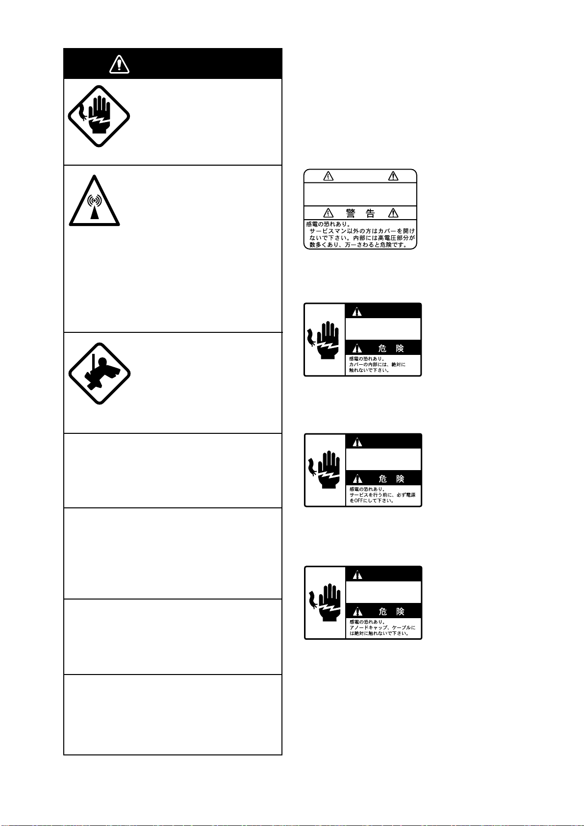
This radar system contains the danger/
warning labels shown below. Do not remove
the labels. If a label is peeling off or is illegible, contact a FURUNO agent for replacement.
WARNING
To avoid electrical shock, do not
remove cover. No user-serviceable
parts inside.
Name : Warning Label
Type : 86-003-1011
Code No. : 100-236-230
DANGER
Electrical shock hazard.
Do not touch parts inside
this cover.
Serious injury or death can
result if someone falls from
the radar scanner mast.
Do not disassemble or modify the
equipment.
Fire, electrical shock or serious injury can
result.
Turn off the power immediately if water
leaks into the equipment or the equipment is emitting smoke or fire.
Continued use of the equipment can cause
fire or electrical shock.
Use the proper fuse.
Fuse rating is shown on the equipment.
Use of a wrong fuse can result in equipment
damage.
Keep heater away from equipment.
Name : Danger Label
Type : 14-055-4202
Code No. : 100-245-220
DANGER
Electrical shock hazard.
Turn off power before
servicing.
Name : Danger Label
Type : 66-022-2012
Code No. : 100-237-730
DANGER
Electrical shock hazard.
Do not touch anode cap
or its cable.
Name : Danger Label
Type : 14-055-4201
Code No. : 100-243-450
Heat can alter equipment shape and melt
the power cord, which can cause fire or
electrical shock.
ii
Page 5

TABLE OF CONTENTS
INTRODUCTION.................................................................................v
SYSTEM CONFIGURATION.............................................................vi|
MENU TREE ....................................................................................viii
OPERATIONAL OVERVIEW
1.1 Turning on the Power ................................................................................................... 1-1
1.2 Transmitter ON............................................................................................................. 1-1
1.3 Control Description....................................................................................................... 1-2
1.4 CRT Brilliance .............................................................................................................. 1-3
1.5 Control Panel Backlighting........................................................................................... 1-3
1.6 Tuning the Receiver ..................................................................................................... 1-3
1.7 Degaussing the Screen................................................................................................ 1-4
1.8 Initializing the Compass Readout ................................................................................ 1-4
1.9 On-screen Legends and Markers ................................................................................ 1-5
1.10 Presentation Modes ................................................................................................... 1-6
1.11 Selecting the Range Scale ......................................................................................... 1-8
1.12 Entering Own Ship’s Speed ....................................................................................... 1-9
1.13 Pulselength, Echo Stretch........................................................................................ 1-10
1.14 Adjusting the Sensitivity ........................................................................................... 1-12
1.15 Suppressing Sea Clutter .......................................................................................... 1-12
1.16 Suppressing Precipitation Clutter............................................................................. 1-13
1.17 Interference Rejector ............................................................................................... 1-13
1.18 Measuring the Range............................................................................................... 1-14
1.19 Measuring Bearing................................................................................................... 1-14
1.20 Collision Assessment by the Offset EBL .................................................................. 1-15
1.21 Measuring Range and Bearing Between Two Targets ............................................. 1-15
1.22 Setting a Target Alarm Zone..................................................................................... 1-16
1.23 Off-centering (shift) .................................................................................................. 1-17
1.24 Echo Averaging........................................................................................................ 1-18
1.25 Electronic Plotting Aid (EPA) .................................................................................... 1-19
1.26 Target Trails (Echo T rails) ........................................................................................ 1-22
1.27 Parallel Index Lines.................................................................................................. 1-25
1.28 Origin Mark............................................................................................................... 1-25
1.29 Zoom ........................................................................................................................ 1-26
1.30 Markers .................................................................................................................... 1-26
1.31 User Keys (F1, F2, F3) ............................................................................................ 1-27
1.32 Function Keys .......................................................................................................... 1-27
1.33 Suppressing Second-trace Echoes.......................................................................... 1-29
1.34 Adjusting Brilliance of Screen Data.......................................................................... 1-29
1.35 Noise Rejector.......................................................................................................... 1-30
1.36 Time Alarm ............................................................................................................... 1-30
1.37 Enhanced Video....................................................................................................... 1-30
1.38 Degaussing Interval ................................................................................................. 1-31
1.39 Navigation Data........................................................................................................ 1-31
1.40 Video Contrast ......................................................................................................... 1-32
iii
Page 6

1.41 Clutter Sweep........................................................................................................... 1-32
1.42 Outputting Target Position........................................................................................ 1-32
1.43 Background Color .................................................................................................... 1-33
1.44 Selecting Range Scales........................................................................................... 1-33
1.45 Selecting Bearing Scale Format .............................................................................. 1-33
1.46 A/D Converter Curve Setting.................................................................................... 1-34
1.47 Enlarging Close-in Targets....................................................................................... 1-34
1.48 Alarms ...................................................................................................................... 1-35
1.49 Peformance Monitor................................................................................................. 1-36
RADAR OBSERVATION
2.1 General ........................................................................................................................ 2-1
2.2 False Echoes ............................................................................................................... 2-2
2.3 SART (Search and Rescue Transponder) ................................................................... 2-3
2.4 RACON (Radar Beacon).............................................................................................. 2-5
MAINTENANCE, TROUBLESHOOTING
3.1 Periodic Maintenance Schedule .................................................................................. 3-1
3.2 Life Expectancy of Major Parts .................................................................................... 3-2
3.3 Fuse Replacement....................................................................................................... 3-3
3.4 Replacement of Batteries............................................................................................. 3-3
3.5 Simple Troubleshooting ............................................................................................... 3-3
3.6 Advanced-level Troubleshooting .................................................................................. 3-4
3.7 Diagnostic Test............................................................................................................. 3-7
PARTS LOCATION ..........................................................................4-1
SPECIFICATIONS.........................................................................SP-1
INDEX
Declaration of Conformity (FR-1760DS)
iv
Page 7

INTRODUCTION
A Word to the Owner of This FURUNO Radar
Thank you for purchasing this FURUNO radar . We are confident you will discover why FURUNO
has become synonymous with quality and reliability.
Dedicated in the design and manufacture of marine electronics equipment for half a century,
FURUNO Electric Company has gained an unrivaled reputation as a world leader in the industry. This is the result of our technical excellence as well as our worldwide distribution and
service network.
Please carefully read and follow the safety information set forth in this manual before attempting to operate the equipment and conduct any maintenance. Your radar set will perform to the
utmost of its ability only if it is operated and maintained in accordance with the correct procedures.
Features
■ FR-1760DS is 60kW, S-band radar , FR-1710 is 10kW, X-band radar and FR-1725 is 25kW ,
X-band radar.
■ Daylight-bright rasterscan 17-inch multi-color, high-resolution display
■ New microprocessing technology with high-speed high-density gate array and software
expertise
■ Easy operation by combination of discrete keys, rotary controls, and menu operation, all
logically arranged and configured
■ Electronic Plotting Aid (EPA) fitted standard, Automatic Tracking Aid (ATA) option
■ Reliable CPA and TCPA warning in any plotting mode, accurate target data
■ The Clutter Sweep feature suppresses sea and rain clutters within an operator-selected
area.
■ A Video Plotter (Chart Plotter) and Performance Monitor are also optionally available.
v
Page 8
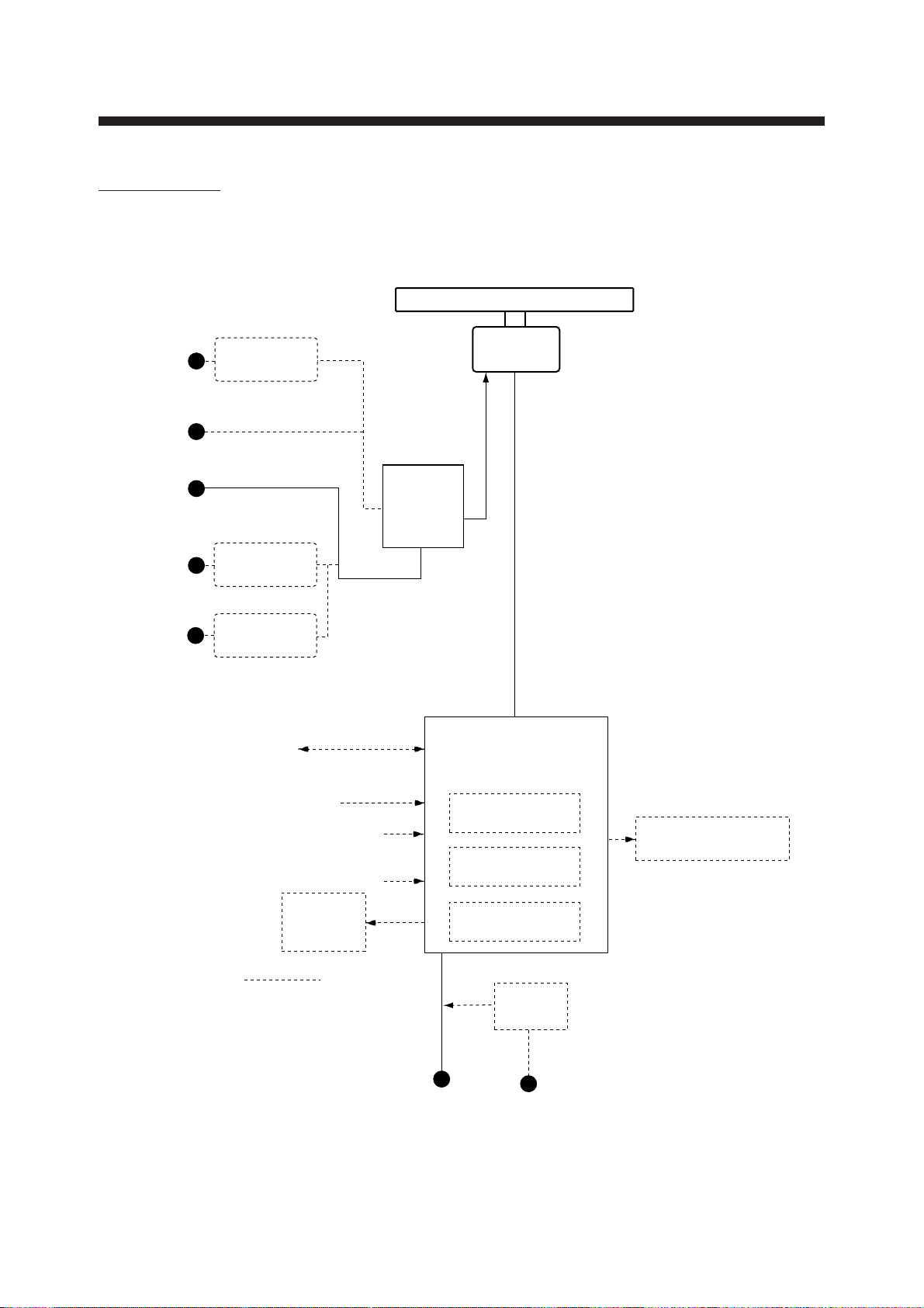
FR-1760DS
SYSTEM CONFIGURATION
ANTENNA UNIT
110/115/
220 VAC,
1φ, 50/60 Hz
100 VAC,
1φ, 50/60 Hz
100/110/
115 VAC,
1φ, 50/60 Hz
220 VAC,
1φ, 50/60 Hz
440 VAC,
1φ, 50/60 Hz
Rectifier
RU-3305
Rectifier
RU-1758
Rectifier
RU-1803
Serial Data
(I/O)
GPS, etc.
Speed Log
Pulse Input
Water temperature,
water depth
Gyrocompass
External
Buzzer
OP03-21
For de-icer
POWER
SUPPLY
UNIT
PSU-002
DISPLAY UNIT
RDP-120
ATA Board
ARP-17
Gyro Converter
GC-8A
Video Plotter
RP-17 Board
SN4A-RSB-0051-N
SN4A-RSB-0051-I
SN5A-RSB-0051-N
SN5A-RSB-0051-I
Remote Display
FMD-8010/FMD-811
Option
Ship’s Mains
24/32 VDC
vi
Rectifier
RU-3424
100/110/115/220/230 VAC,
1φ, 50/60 Hz
Page 9
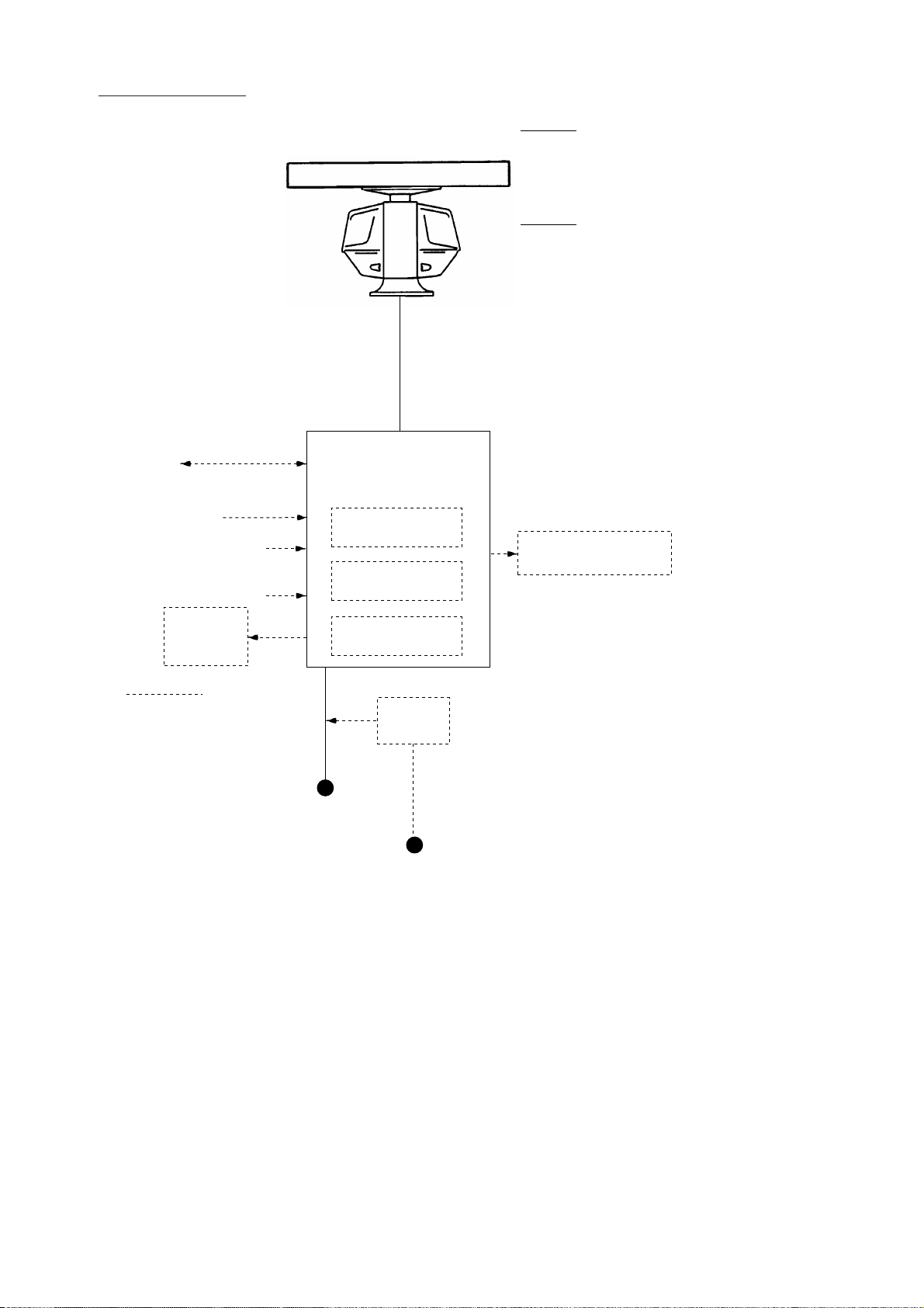
FR-1710/1725
Serial Data
GPS, etc.
Speed Log
Water temperature,
water depth
Gyrocompass
OP03-21
(I/O)
Pulse Input
External
Buzzer
ANTENNA UNIT
DISPLAY UNIT
RDP-120
ATA Board
ARP-17
Gyro Converter
GC-8A
Video Plotter
RP-17 Board
FR-1710
XN12AF-RSB0074-062 (24 rpm)
XN20AF-RSB0074-062 (24 rpm)
XN12AF-RSB0075-062 (42 rpm)
XN20AF-RSB0075-062 (42 rpm)
FR-1725
XN20AF-RSB0074-063 (24 rpm)
XN24AF-RSB0074-063 (24 rpm)
XN20AF-RSB0075-063 (42 rpm)
XN24AF-RSB0075-063 (42 rpm)
Remote Display
FMD-8010/FMD-811
Option
Rectifier
RU-3424
Ship’s Mains
24/32 VDC
or
100/110/115/220/230 VAC,
1φ, 50/60 Hz
*
*: FR-1725 only
Note: The display unit is available
in AC or DC specification.
vii
Page 10
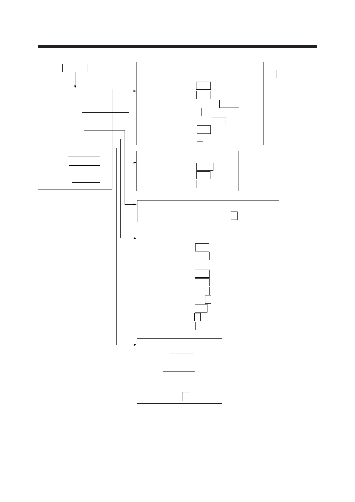
MENU key
TGT TRAIL
MENU
1. VIDEO PLOT*
2. TGT TRAIL
3. TGT ALARM
4. PANEL DIM
5. ECHO SIG
6. FUNC
7. PLOT 1
8. MARK 2
9. BRILL 3
0. OTHER 4
* Requires Video Plotter
RP-17.
MENU TREE
1. TIME 15S 30S 1M 3M
6M 15M 30M CONT
2. MODE REL TRUE
3. SHADE MONO MULTI
4. LEVEL 1 2 3
5. TRAIL COPY OFF ON
6. THIN TRAIL OFF ON
7. THIN MODE 1 2 3 4
TGT ALARM
1. AREA NO1 NO2
2. MODE1 IN OUT
3. MODE2 IN OUT
DIMMER
1. PANEL BRIGHT 7 6 5 4 3 2 DIM
: Default
settings
ECHO SIG
1. TGT COLOR YEL GRN COLOR*
2. ECHO AVG OFF 0.5 1 2 3
3. INT REJ OFF 1 2 3
4. N REJ OFF ON
5. ENHANCE OFF ON
6. 2ND ECHO OFF ON
7. CONTRAST 1 2 3
8. CLTR SWEEP
9. SWEEP LVL 1 2 3
0. CNTR ENHANCE OFF ON
FUNC
1. FUNC1 5
2. FUNC2
3. F•1 6
4. F•2
5. F•3
6. A/D CURVE A B C D
* COLOR not shown
on HK type radar.
OFF ON(LINK) ON(FIX)
viii
Page 11
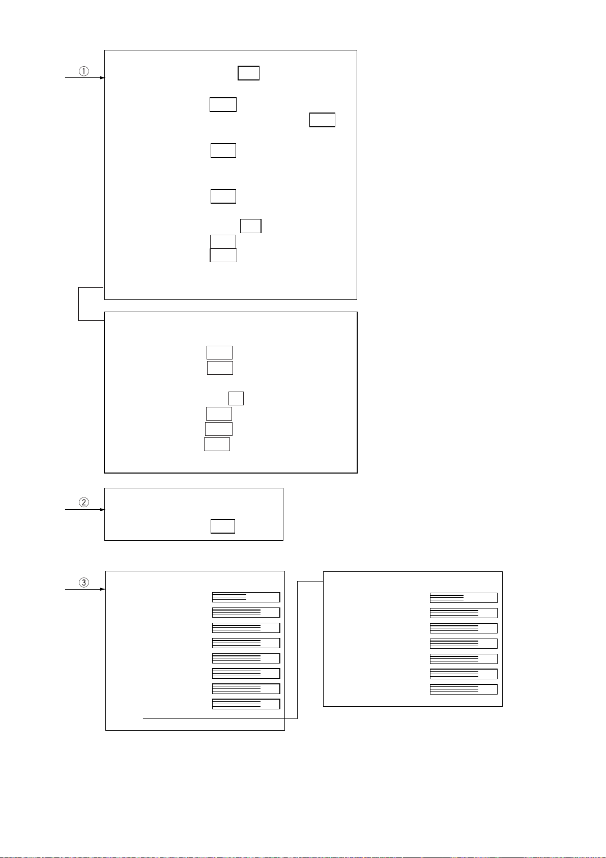
PLOT MENU 1
1. MARK DISP OFF ON
2. ERASE
3. VEC REF REL TRUE
4. VEC TIME 30S 1M 3M 6M
15M 30M
5. CPA SET OFF 0.5NM 1NM 1.5NM
2NM 3NM 4NM
5NM 6NM
6. TCPA SET 30S 1M 2M 3M
4M 5M 6M 12M 15M
7. TRACK OFF ON
8. AUDIO ALARM OFF ON
9. INTVAL* 30S 1M 2M 3M 6M
0. ↓*
[0]
* Requires Automatic Tracking Aid
ARP-17 (Option).
PLOT MENU 2*
1. ↑
2. AUTO OFF ON SET
3. GUARD ZONE OFF ON SET
4. TRACK TEST
5. LAND DISCRIM 0 1 2 3 4 5
6. TTM OFF REL TRUE
7. VEC START 1MIN 20SCAN
8. REF TGT VECTOR OFF ON
9. TARGET BASED SPEED
MARK
1. ERASE
2. MODE REL TRUE
BRILL
1. TGT TRAIL
2. CHARACTER
3. HDG LINE
4. EBL/VRM
5. CURSOR
6. MARK
7. PLOT
8. OS SYMB
*
9. ↓
PLOTTER BRILL*
1. ↑
2. LAND
3. GRID
4. MARK
5. OS TRACK
6. TGT TRACK
7. COLOR
* Requires Video Plotter RP-17 (option).
ix
Page 12
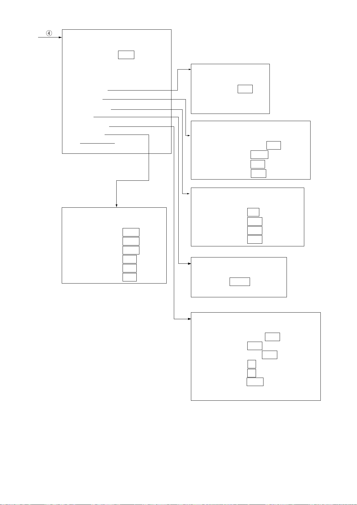
OTHER
1. HDG SET
2. SPD MODE MAN LOG NAV
LOG (S-BT)
LOG (S-WT)
3. MAN SPD
4. DRIFT SET
5. DISPLAY
6. MARK/LINE
7. TUNE
8. NAV DATA
9. EBL/VRM
0. ↓ 7
EBL/VRM
1. ↑
2. CURS BRG REL TRUE
3. EBL1 REL TRUE
4. EBL2 REL TRUE
5. CURS RNG NM KM SM
6. VRM1 NM KM SM
7. VRM2 NM KM SM
DISPLAY
DRIFT SET
1. ↑
2. SET&DRIFT OFF ON
3. SET
4. DRIFT
1. ↑
2. NAV DATA OFF ON
3. DISPLAY MAIN SUB
4. SART OFF ON
5. P M OFF ON
MARK/LINE
1. ↑
2. INDEX LINES 2 6
3. STERN MARK OFF ON
4. SHIP’S MARK OFF ON
5.
BEARING SCALE
1. ↑
2. MODE AUTO MAN
3. TUNE SET
360 COMPASS
TUNE
NAV DATA
1. ↑
2. NAV SEL ANY GPS LC
3. EXT WP OFF ON
4. OS POSN OFF L/L TD
5. DEPTH M FA
6. TEMP °C °F
7. TIME DIF UTC LOCAL
8. LOCAL TIME
ft
x
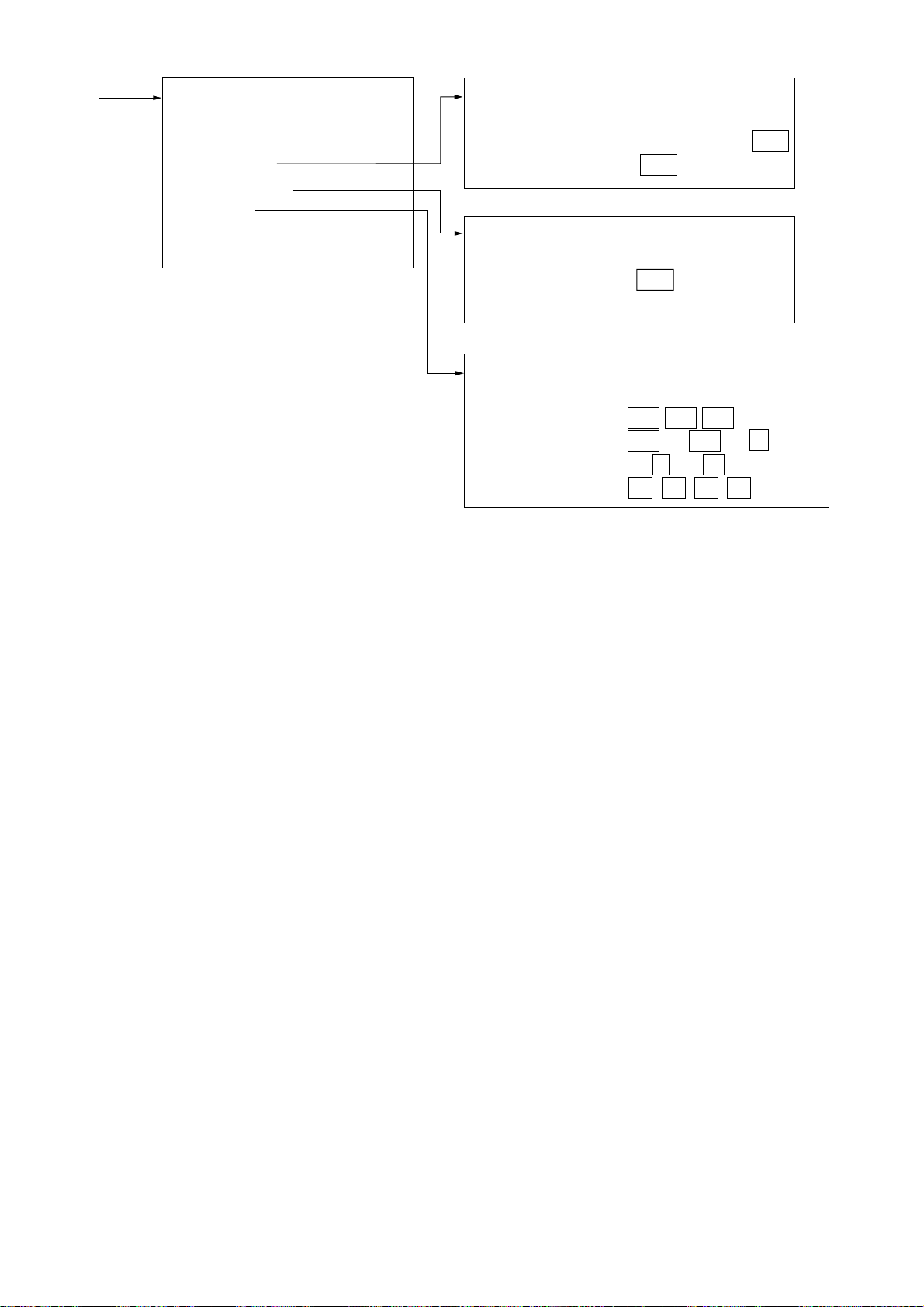
Page 13

5
FUNC 1 MENU
1. ↑
2. FUNC SEL COAST OCEAN
R-SEA RAIN
BIRD-N BIRD-F
3. ECHO AVG OFF 0.5 1 2 3
4. INT REJ OFF 1 2 3
5. STRETCH OFF 1 2
6. N REJ OFF ON
7. ENHANCE OFF ON
8. CONTRAST OFF 1 2 3
9. A/C AUTO OFF ON
[F•2 MENU]
1. TRAIL TIME 26. HUTB MODE
2. TRAIL MODE 27. TUNE A/M
3. TRAIL SHADE 28. EXT WP
4. TRAIL LEVEL 29. OS POSN
5. ALARM AREA 30. CURS BRG
6. ALARM MODE 31. EBL1 T/R
7. PANEL DIMMER 32. EBL2 T/R
8. TGT COLOR 33. CURS RNG
9. ECHO AVG 34. VRM1 RNG
10. INT REJ 35. VRM2 RNG
11. ECHO STRETCH 36. CLTR SWEEP
12. NOISE REJ 37. MARK MENU
13. ECHO ENHANCE 38. DISP MODE
14. 2ND ECHO 39. A/D CURVE
15. CONTRAST 40. DRIGIN MARK
16. PLOT MENU 41. DEST ON CSR
17. MARK MODE
18. BRILL MENU
19. DRIFT MENU
20. NAV DATA
21. DISPLAY
22. SART
23. TIME ALARM
24. STERN MARK
25. OS MARK
Select by VRM knob
and hit ENTER key.
37 and 38 shown with connection of RP-17.
xi
Page 14
7
OTHER
1. ↑
2. TEST
3. DEGAUSS
4. TIME ALARM
5. RANGE
6. INSTALL*
*: See Installation Manual.
DEGAUSS
1. ↑
2. DEGS INTV OFF 30S 1M 2M
3. DEGS DEG OFF 45° 90° 135°
TIME ALARM
1. ↑
2. ALARM INTV OFF 3M 6M
12M 15M 20M
RANGE
1. ↑
2. RANGE 1/8 1/4 1/2
3/4 1 1.5 2 3
4 6 8 12 16
24 32 48 72 96 120
FR-1760DS Max. range: 120 NM
FR-1710 Max. range: 72 NM
FR-1725 Max. range: 96 NM
xii
Page 15
OPERATIONAL OVERVIEW
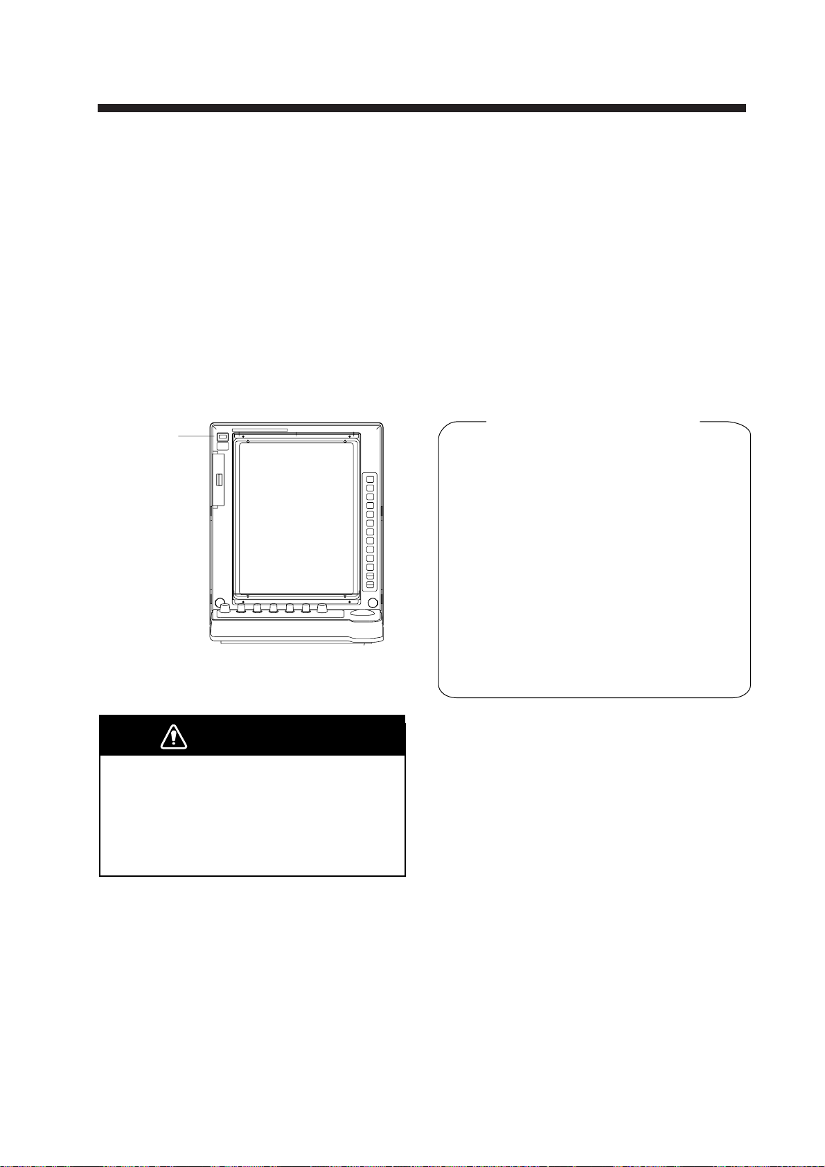
1.1 Turning on the Power
The [POWER] switch is located at the top
left corner of the display unit. Push it to switch
on the radar set. To turn off the radar , push it
again. The screen shows the bearing scale
and digital timer approximately 15 seconds
after power-on. The timer counts down three
minutes of warm-up time. During this period
the magnetron, that is, the transmitter tube,
is warmed for transmission. When the timer
has reached 0:00, the indication STBY appears, indicating that the radar is now ready
to transmit pulses.
POWER
switch
1.2 T ransmitter ON
After the power has been turned on and the
magnetron has warmed, STBY (Standby) appears at the screen center, indicating the radar is ready to transmit radar pulses.
Press the [STBY/TX] key to transmit.
When you won’t be using the radar for an
extended period, but you want to keep it in a
state of readiness, place it in standby by
pressing the [STBY/TX] key. The display
shows STBY when the radar is in standby.
Video Lockup Recovery
Video freeze-up or lock-up, can occur unexpectedly on digital rasterscan radars. This is
mainly caused by heavy spike noise in the
power line and can be noticed by carefully
watching the nearly invisible sweep line.
If you suspect that the picture is not updated
every scan of the antenna or no key entry is
accepted notwithstanding the apparently
normal picture, do Quick Start to restore
normal operation.
Figure 1-1 Location of power switch
DANGER
Before turning on the radar, make sure
that there is no one near the antenna.
Serious injury or even death may result if
a rotating antenna strikes someone standing
nearby.
1. Turn off the POWER switch and turn it on
again within 10 seconds.
2. Push the Transmit switch labeled STBY/TX
for Transmit status.
1-1
Page 16
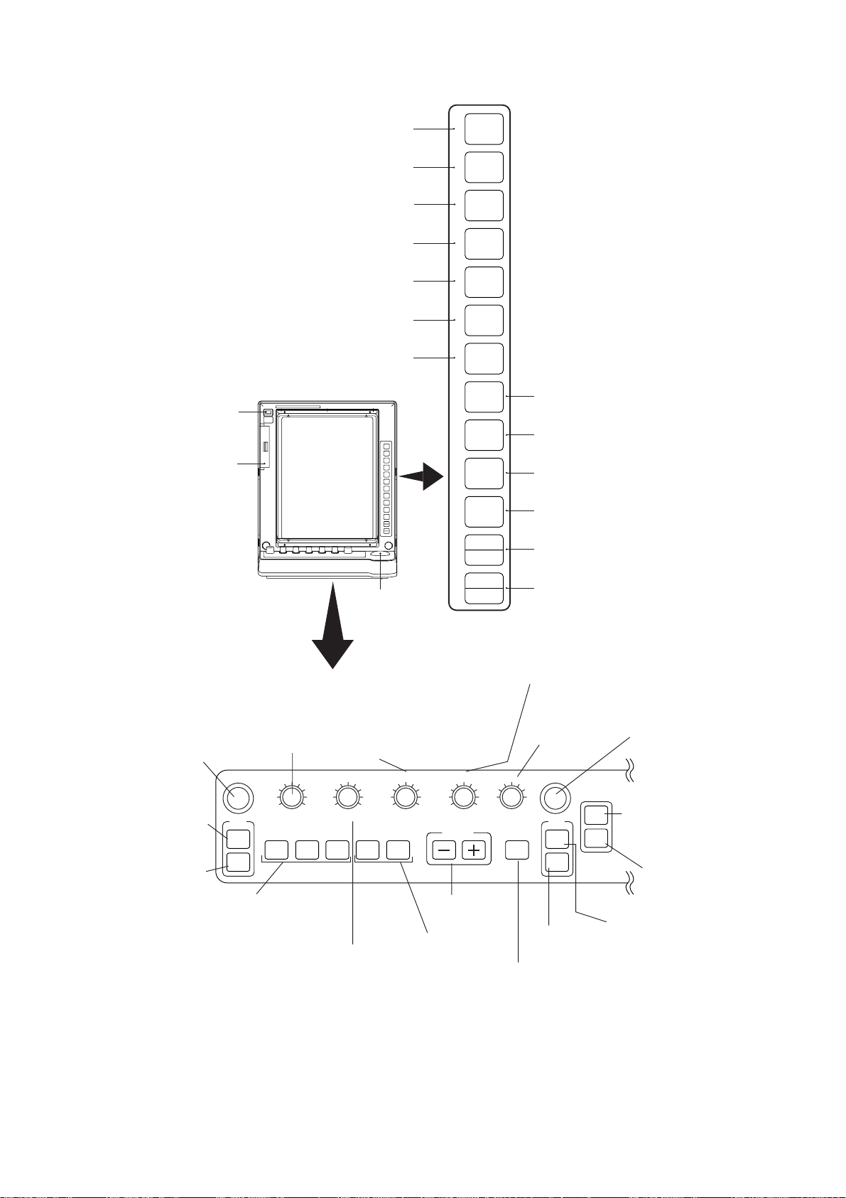
1.3 Control Description
Selects presentation mode.
1
MODE
Offset EBL origin to measure range,
Turns power on/off.
Chart card slot
(Requires video
plotter.)
ROTATE: Rotates EBL.
PUSH: Degausses
screen.
Alternately selects
No.1 EBL,
No.2 EBL.
Erases EBL.
Turns on/off target trails.
Enables/disables guard zone.
Off centers picture.
Turns zoom function on/off.
Turns parallel index lines on/off.
bearing between two targets;
predict collision course.
TRACKBALL
Shifts cursor.
ROT A TE: Adjusts
screen brilliance.
PUSH: Selects background color.
DEGAUSS (PUSH)
EBL
ON
OFF
BKGND COLOR (PUSH)
BRILL
F1
F2 F3
ROTATE: Suppresses
sea clutter.
PUSH: Turns on/off
automatic clutter
suppression.
TLL (PUSH)
A/C RAIN
A/C AUTO (PUSH)
Activates
desired
function.
ROTATE: Suppresses
precipitation clutter.
PUSH: Outputs
target position.
2
3
4
5
6
7
8
9
0
HL OFF (PUSH)
A/C SEA
GAIN
RANGE
Selects range
scale.
Turns on/off
menu-selected
function.
TGT
TRAIL
GZ
ALARM
SHIFT
ZOOM
INDEX
LINE
EBL
OFFSET
MARK
RINGS
Inscribes mark.
Adjusts brilliance of fixed range
rings.
PREV
MENU
MENU
CANCEL
CLEAR
ENTER
SELECT
Displays previous menu.
Opens/closes menu.
Menu open: Cancels item selected.
Menu closed: Erases mark.
Menu open: Registers selection.
Menu closed: Displays data of
selected plot symbol.
ROT A TE: Adjusts gain.
PUSH: Temporarily erases heading line,
markers (stern, north) OS symbol.
Selects pulselength, echo
stretch.
Adjusts radius
of VRM.
10-1
2
-2
3
-3
ECHO
STBY
TX
VRM
ON
OFF
ACQ
Manually acquires
target (plotting
AUDIO
OFF
function).
Silences timer,
ATA and EPA
alarms.
Alternately selects
Erases VRM.
No.1 VRM, No.2 VRM.
Transmit/standby
switch
1-2
Figure 1-2 Control description
Page 17

1.4 CRT Brilliance
1.6 Tuning the Receiver
Operate the BRILL control on the control
panel of the display unit to adjust the entire
screen brightness. Note that the optimum
point of adjustment varies with ambient lighting conditions, especially between daytime
and nighttime.
1.5 Control Panel Backlighting
1. Press the [MENU] key.
MENU
1. VIDEO PLOT
2. TGT TRAIL
3. TGT ALARM
4. PANEL DIM
5. ECHO SIG
6. FUNC
7. PLOT
8. MARK
9. BRILL
0. OTHER
Figure 1-3 Main menu
2. Press the [4] key twice. The following display appears.
DIMMER
1. PANEL BRIGHT 7 6 5 4 3 2 DIM
Figure 1-4 Screen for adjustment
of panel dimmer
3. Press the [1] key to select backlighting
level desired.
4. Press the [ENTER/SELECT] key to register your selection and the [MENU] key
to close the menu.
The radar is set for automatic tuning at the
factory.
Automatic tuning
The radar receiver is tuned automatically
each time the transmitter is turned on. The
tuning indicator and the label AUTO at the
top right corner of the display unit shows the
tuning circuit is working. The receiver may
become detuned, in automatic tuning, if own
ship’s radar receives the radar signal of another shipborne radar. To retune, press the
[STBY/TX] key twice.
Manual tuning
1. Set up for manual tuning following the
procedure shown below.
2. While observing the picture on the 48 mile
scale, press and hold down the GAIN
control while slowly adjusting the VRM rotary control to find the best tuning point.
This condition is where the tuning indicator lights to about 80% of its total length.
Note that the tuning indication will never
extend to full length.
Selection of manual or automatic
tuning
1. Press the [MENU] key.
2. Press the [0] key twice to display the
OTHER menu.
OTHER
1. HDG SET
2. SPD MODE MAN LOG NAV
LOG (S-BT)
LOG (S-WT)
3. MAN SPD
4. DRIFT SET
5. DISPLAY
6. MARK/LINE
7. TUNE
8. NAV DATA
9. EBL/VRM
0. ↓
Figure 1-5 OTHER menu
1-3
Page 18

3. Press the [7] key twice to display the
TUNE menu.
TUNE
1. ↑
2. MODE AUTO MAN
3. TUNE SET
Figure 1-6 TUNE menu
4. Press the [2] key to select the option
AUTO or MAN from the MODE field.
5. Press the [ENTER/SELECT] key.
1.8 Initializing the Compass Readout
With a compass interfaced with the radar,
ship’s heading is displayed at the top of the
screen. Upon turning on the radar, match the
on-screen HDG readout with the compass
reading by the procedure shown below. Once
you have set the initial heading correctly , resetting is not usually required. However , if the
HDG readout goes wrong for some reason,
repeat the procedure to correct it.
6. Press the [MENU] key to close the menu.
1.7 Degaussing the Screen
Each time the radar is turned on, the degaussing circuit automatically demagnetizes
the CRT screen to eliminate color contamination caused by earth’s magnetism or magnetized ship structure.
The screen is also degaussed automatically
at certain time intervals, which may be selected on the menu. While being degaussed,
the screen may be disturbed momentarily
with vertical lines. If you wish to degauss by
manual operation, push the EBL rotary control (DEGAUSS control).
1. Press the [MENU] key to display the main
menu.
2. Press the [0] key twice to display the
OTHER menu.
OTHER
1. HDG SET
2. SPD MODE MAN LOG NAV
LOG (S-BT)
LOG (S-WT)
3. MAN SPD
4. DRIFT SET
5. DISPLAY
6. MARK/LINE
7. TUNE
8. NAV DATA
9. EBL/VRM
0. ↓
Figure 1-7 OTHER menu
1-4
3. Press the [1] key to select HDG SET.
4. Operate the VRM rotary control to duplicate the compass readout on the radar
menu display.
5. Press the [ENTER/SELECT] key.
6. Press the [MENU] key to close the menu.
Page 19
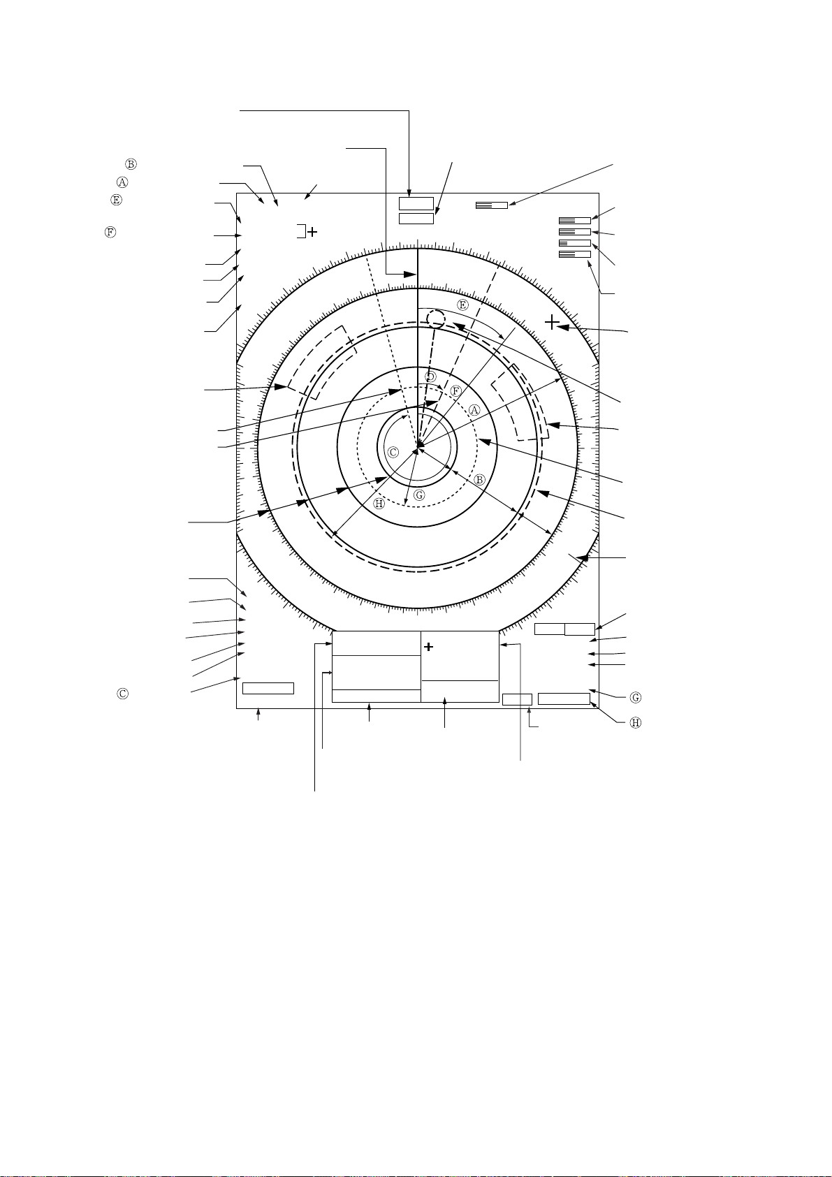
1.9 On-screen Legends and Markers
Heading
(Requires heading sensor.)
Range ring interval
Range to cursor
Range to cursor
Bearing to cursor
Presentation mode
Pulselength
Offcenter
Function
Target alarm
zone No. 1
No. 1 EBL
No. 2 EBL
Range rings
Interference
rejector
Echo stretch
Noise rejector
Auto clutter
reduction
Echo averaging
Video contrast
No. 1 EBL
bearing
Heading line
8
/2 NM
4.111NM
103.7°R
HU
PULSE MIP
OFF CENT
FUNC1
COAST
320
310
300
290
2
8
0
2
7
0
2
6
0
2
5
0
240
230
220
IR2
ES1
NR
A/C AUTO
EAV1
VIDEO
CONTRAST1
EBL
345.6° R
23.0° R
No. 2 EBL
bearing
2nd trace echo
rejector
2nd Echo
340
340
330
330
320
210
200
OS
(L/L)
135°
RNG
WP
BRG
TTG 00:20
9/22
12:34
Date, time
Range, bearing
to waypoint
Own ship position
HDG 234.5°
LOG 12.8 KT
350
350
190
40.36’N
34°
18.23’E
123.9NM
220°R
UTC
Log speed (Requires log device.)
AUTO
GAIN
A/C SEA
A/C RAIN
BRILL
000
000
010
010
020
020
030
030
040
040
140
150
160
170
180
40°21.211’N
127°21.321’E
TTG 00 : 50
TEMP 20.1°C
DEPTH 123.5M
Water temperature,
water depth
T-ALM
02:30
REL TRAIL
30S 0 : 16
2.093 NM
4.465 NM
Timer alarm
countdown
Cursor position,
time-to-go
050
050
060
060
120
130
GZ1
GZ2
OUT IN
VRM
0
7
0
110
0
7
0
0
8
0
0
9
0
1
0
0
Tuning bar
GAIN setting
A/C SEA setting
A/C RAIN setting
BRILL setting
Cursor
Waypoint marker
Target alarm
zone No. 2
No.1 VRM
No.2 VRM
North marker
Guard zone (active one
is circumscribed)
Guard zone mode
Target trail reference
Target trail time,
elapsed time
No. 1 VRM
range
No. 2 VRM
range
Figure 1-8 On-screen legends and markers
Note: The cursor functions to measure the range and bearing to a radar target, and is permanently displayed. It can be returned to the screen center by pressing the VRM rotary control.
1-5
Page 20
1.10 Presentation Modes
This radar has the following presentation
modes: Head-up, Head-up/TB, Course-up,
North-up, and True Motion.
Selecting presentation mode
Press the [MODE] key on the panel at the
right side of the display unit. Each time the
[MODE] key is pressed, the presentation
mode and mode indication at the upper-left
corner of the screen change cyclically.
Note: When a failure occurs in the gyrocompass, the radar will automatically be switched
to unstabilized presentation mode. All compass related data will read Relative values.
Loss of Compass Signal
When the compass signal is lost, the buzzer
sounds once, the presentation mode becomes
head-up and the compass readout shows
xxx.x°. After restoring the compass signal,
press the [MODE] key to display the compass
readout. Readjust the compass readout as
shown on page 1-4. Also HDG SIGNAL
MISSING appears at the bottom of the screen.
Presentation mode,
representative display
Heading
marker
North
marker
300
290
280
270
260
250
240
North
marker
310
300
290
280
270
320
310
230
220
340
330
320
260
250
210
330
240
350
200
340
000
230
350
190
010
220
The bearing scale rotates with
a compass signal.
Heading
line
000
010
170
180
Heading
marker
030
020
200
210
020
160
190
040
030
150
050
180
040
050
130
140
Heading
line
060
070
160
170
120
060
150
080
Description
Head-up Mode
A display without azimuth stabilization in which
the line connecting the center with the top of the
display indicates own ship’s heading.
070
080
090
100
110
The target pips are painted at their measured distances and in their directions relative to own ship’s
heading.
A short line on the bearing scale is the north marker
indicating compass north. A failure of the compass
input will cause the north marker to disappear and
the HDG readout to show asterisks xxx.x°.
Head-up TB (True Bearing) Mode
Radar echoes are shown in the same way as in the
head-up mode. The difference from normal head-up
presentation lies in the orientation of the bearing
090
100
110
120
130
140
scale. The bearing scale is compass stabilized, that
is, it rotates in accordance with the compass signal,
enabling you to know own ship’s heading at a glance.
This mode is available only when the radar is interfaced with a compass.
If the compass fails, the bearing scale returns to the
state of head-up mode.
1-6
Page 21
Presentation mode,
representative display
Description
North
marker
330
320
310
300
290
280
270
260
300
290
280
270
260
250
240
310
230
250
340
320
220
240
350
210
330
000
230
010
220
340
200
Heading
marker
030
020
200
210
North
000
350
190
180
190
010
170
040
180
020
160
Heading
line
050
060
070
160
170
Heading
line
030
040
050
130
140
150
080
090
100
110
120
130
140
150
Heading
marker
060
070
080
090
100
110
120
Course-up Mode
An azimuth stabilized display in which a line connecting the center with the top of the display indicates own
ship’s intended course (namely, own ship’s previous
heading just before this mode has been selected).
Target pips are painted at their measured distances
and in their directions relative to the intended course
which is maintained at the top of screen while the
heading line moves in accordance with ship’s yawing
and course changes. This mode is useful to avoid
smearing of picture during course change. After a
course change, press the [SHIFT] key to reset the
picture orientation if you wish to continue using the
course-up mode. The heading line gets back to
perpendicular.
North-up Mode
In the north-up mode, target pips are painted at their
measured distances and in their true (compass)
directions from own ship, north being maintained
up of the screen. The heading line changes its
direction according to the ship’s heading.
If the compass fails, the presentation mode changes
to head-up and the north marker disappears. Also,
the HDG readout shows xxx.x°.
1-7
Page 22
Presentation mode,
representative display
Description
270
280
260
290
250
300
240
310
230
North
marker
330
320
220
210
340
200
350
190
000
180
010
170
020
160
Heading
line
030
040
140
150
050
060
120
130
Heading
marker
070
080
090
100
110
True Motion Mode
Own ship and other moving objects move in accordance with their true courses and speeds. In ground
stablized TM, all fixed targets, such as landmasses,
appear as stationary echoes. In the sea stablized TM
without set and drift input, the landmass can move on
the screen.
When own ship reaches a point corresponding to
75% of the radius of the display, the own ship is
automatically reset to a point of 75% radius opposite
to the extension of the heading line passing through
the display center. Resetting can be made at any
moment before the ship reaches the limit by pressing
the [SHIFT] key. Automatic resetting is preceded by a
beep sound.
If the compass fails, the presentation mode is
changed to the head-up mode and the north marker
disappears. The HDG readout at the top of the
screen shows xxx.x°.
North
Heading
line
300
290
280
270
260
250
240
350
340
330
320
310
230
220
210
200
(a) True motion
is selected
000 010
marker
020
030
040
050
060
070
080
090
100
110
120
130
140
150
160
170180190
300
290
280
270
260
250
240
340
330
320
310
230
220
210
200
(b) Own ship has reached a
point 75% of display radius
Automatic resetting of own ship position in true motion mode
1.11 Selecting the Range Scale
The range selected automatically determines
the range ring interval, the number of
range rings and pulse repetition rate, for
optimal detection capability in short to long
ranges. You can select pulselength with
the ECHO control. For details, see paragraph 1.13.
000 010
350
020
030
040
050
060
070
080
090
100
110
120
130
140
150
160
170180190
320
310
300
290
280
270
260
250
240
230
220
000 010
350
340
330
210
200
020
030
040
050
060
070
080
090
100
110
120
130
140
150
160
170180190
(c) Own ship is automatically
reset to 75% of radius
Press the [RANGE] key to select a range
scale. The range, range ring interval and
pulselength appear at the top left corner of
the display.
1-8
Page 23
1.12 Entering Own Ship’s
Speed
4. Press the [ENTER/SELECT] key to confirm your selection followed by the
[MENU] key to close the menu.
EPA requires an own ship speed input and
compass signal. The speed can be entered
from a speed log or navaid (automatic) or
through the plotting keypad (manual).
Automatic speed input
1. Press the [MENU] key and the [0] key
twice to show the OTHER menu.
OTHER
1. HDG SET
2. SPD MODE MAN LOG NAV
LOG (S-BT)
LOG (S-WT)
3. MAN SPD
4. DRIFT SET
5. DISPLAY
6. MARK/LINE
7. TUNE
8. NAV DATA
9. EBL/VRM
0. ↓
Figure 1-9 OTHER menu
2. Press the [2] key to select the menu item
SPD MODE.
3. Press the [2] key again to select the LOG
or NAV.
LOG: Pulse input from speed
log, serial data
NAV: Speed data from naviga-
tion equipment
Note: Be sure not to select a LOG option or
NAV when respective equipment is not connected. If the log signal or navaid signal is
not provided, the ship’s speed readout at the
screen top will be blank.
Manual speed input
If the radar is not interfaced with a speed log,
or the speed log does not feed correct speed
enter the ship’s speed as follows:
1. Press the [MENU] key and the [0] key
twice to show the OTHER menu.
2. Press the [2] key to select MAN from the
SPD MODE field, and then press the [ENTER/SELECT] key.
3. Press the [3] key twice to select the MAN
SPD field.
4. Enter speed with the numeric keys.
5. Press the [ENTER/SELECT] key to confirm your selection followed by the
[MENU] key to close the menu.
LOG 10.0KT WT
Or NAV
LOG or NAV speed indication
LOG 8.7KT WT
8.5 F ← Fore/Aft
0.5 SB ← Port/STBD
GT
About Ship’s Speed
c’
a
Wind,
⇒
current
LOG (serial data) speed indication
a: Fore/aft speed
b: Port/starboard speed
c: Speed made good (actual speed)
c
Pulse signal: a only (water tracking speed)
Serial speed: a and b
b
Water tracking speed = relative speed
(including error due to wind, current
Ground tracking speed = true speed
(no influence from wind, currents)
Navigator speed: c→c’
Speed input (c) from navgator (GPS, etc.)
c is converted to fore/aft direction (c’) and
displayed on the radar screen.
1-9
Page 24
1.13 Pulselength, Echo Stretch
The ECHO control selects pulselength, and
echo stretch when it is not turned on with a
user key ([F1], [F2], [F3]). The pulselength in
use is displayed at the upper-left position of
the screen using the abbreviations (suffixed
with “P”) shown in the table on the next page.
Echo stretch level (ES1, ES2) in use appears
at the bottom left position, using the indication ES1 or ES2.
Appropriate pulselengths are preset to individual range scales and function keys. Therefore, you are not usually required to select
them. If you are not satisfied with the current
pulselength settings, however, it is possible
to change them by the ECHO control. The
ECHO control settings which can select the
echo stretch are shown in the table below.
The legend and pulselengths are shown in
below.
5271/0171-RFSD0671-RF
sµ70.0:P1Ssµ80.0:PS
sµ51.0:P2Ssµ3.0:P1M
sµ3.0:P1Msµ6.0:P2M
sµ5.0:P2Msµ2.1:PL
sµ7.0:P3M
sµ2.1:PL
Note: The echo stretch magnifies not only
small target pips but also returns (clutter) from
sea surface, rain and radar interference. For
this reason make sure these types of interference have been sufficiently suppressed
before activating this function.
Enlarged in bearing
(circumferential)
direction with ES1
+
If a distant target
is hard to see,
use ES 1.
Enlarged with ES2
+
If a target becomes
smaller as it approaches
own ship, use ES 2.
Figure 1-10 Echo stretch
On long ranges target echoes tend to shrink
in the bearing direction, making them difficult to see. On short and medium ranges such
as 1.5, 3 and 6 nm scales, the same size
targets get smaller on screen as they approach the own ship. These are due to the
inherent property of the radiation pattern of
the antenna. To enhance target video, use
the echo stretch function. There are two
types: echo stretch 1 (ES1) to enlarge in bearing direction for long range detection, and
echo stretch 2 (ES2) to enlarge in range direction.
1-10
Page 25

Table 1-1a ECHO control setting, pulselength and echo stretch (FR-1710/1725)
egnaR sgnitteShctertSohcEdnahtgnelesluPdnanoitisoPlortnoCOHCE
mkmsmn3-2-1-0123
52.0– 521.0P1SP1SP1SP1S1SE,P1S1SE,P1S1SE,P1S
5.052.052.0P1SP1SP1SP1S1SE,P1S1SE,P1S1SE,P1S
57.0–– P1SP1SP1SP1S1SE,P1SP2S1SE,P2S
15.05.0P1SP1SP1SP1S1SE,P1SP2S1SE,P2S
–57.0– P1SP1S1SE,P1SP2S1SE,P2SP1M1SE,P1M
5.1157.0P1SP1S1SE,P1SP2S1SE,P2SP1M1SE,P1M
25.11 P1SP1S1SE,P1SP2S1SE,P2SP1M1SE,P1M
32 5.11SE,P1SP2S1SE,P2SP1M1SE,P1MP2M1SE,P2M
432 1SE,P1SP2S1SE,P2SP1M1SE,P1MP2M1SE,P2M
6– 3 1SE,P2SP1M1SE,P1MP2M1SE,P2MP3M1SE,P3M
844 1SE,P2SP1M1SE,P1MP2M1SE,P2MP3M1SE,P3M
2166 1SE,P2SP1MP2MP3M2SE,P3MPL1SE,PL
6188 1SE,P2SP1MP2MP3M1SE,P3MPL1SE,PL
4221211SE,P1M1SE,P2MP3MPL1SE,PL2SE,PL2SE,PL
2361611SE,P2MP3M1SE,P3MPL1SE,PL2SE,PL2SE,PL
8442421SE,P2MP3M1SE,P3MPL1SE,PL2SE,PL2SE,PL
–2323PLPLPLPL1SE,PL2SE,PL2SE,PL
278484PLPLPLPL1SE,PL2SE,PL2SE,PL
69–– PLPLPLPL1SE,PL2SE,PL2SE,PL
–2727PLPLPLPL1SE,PL2SE,PL2SE,PL
–6969PLPLPLPL1SE,PL2SE,PL2SE,PL
Table 1-1b ECHO control setting, pulselength and echo stretch (FR-1760DS)
egnaR sgnitteShctertSohcEdnahtgnelesluPdnanoitisoPlortnoCOHCE
mkmsmn3-2-1-0123
52.0– 521.0P1SP1SP1SP1S1SE,P1S1SE,P1S1SE,P1S
5.052.052.0P1SP1SP1SP1S1SE,P1S1SE,P1S1SE,P1S
57.0–– P1SP1SP1SP1S1SE,P1S1SE,P1S1SE,P1M
15.05.0P1SP1SP1SP1S1SE,P1S1SE,P1S1SE,P1M
–57.0– P1SP1SP1SP1S1SE,P1SP1M1SE,P1M
5.1157.0P1SP1SP1SP1S1SE,P1SP1M1SE,P1M
25.11 P1SP1SP1SP1S1SE,P1SP1M1SE,P1M
32 5.1P1SP1S1SE,P1SP1M1SE,P1MP2M1SE,P2M
432 P1SP1S1SE,P1SP1M1SE,P1MP2M1SE,P2M
6– 3 P1SP1S1SE,P1MP1M1SE,P1MP2M1SE,P2M
844 P1MP1M1SE,P1MP2M1SE,P2MPL1SE,PL
2166 P1MP1M1SE,P1MP2M2SE,P2MPL1SE,PL
6188 P1MP1M1SE,P1MP2M1SE,P2MPL1SE,PL
422121P1MP1M1SE,P1MP2M1SE,P2MPL1SE,PL
236161P2MP2M1SE,P2MPL1SE,PL2SE,PL2SE,PL
844242P2MP2M1SE,P2MPL1SE,PL2SE,PL2SE,PL
–2323PLPLPLPL1SE,PL2SE,PL2SE,PL
278484PLPLPLPL1SE,PL2SE,PL2SE,PL
69–– PLPLPLPL1SE,PL2SE,PL2SE,PL
–2727PLPLPLPL1SE,PL2SE,PL2SE,PL
–6969PLPLPLPL1SE,PL2SE,PL2SE,PL
021021021PLPLPLPL1SE,PL2SE,PL2SE,PL
1-11
Page 26

1.14 Adjusting the Sensitivity
The GAIN control adjusts the sensitivity of
the receiver. It works in precisely the same
manner as the volume control of a broadcast
receiver, amplifying the signals received.
If the control is set too low, targets will be
hidden in the clutter , while if it is set too high,
both sea clutter and targets will disappear
from the display. In most cases adjust the
control until clutter has disappeared to leeward, but a little is still visible windward.
The proper setting is such that the background noise is just visible on the screen. If
you set up for too little sensitivity, weak echoes may be missed. On the other hand excessive sensitivity yields too much
background noise; strong targets may be
missed because of the poor contrast between
desired echoes and the background noise on
the display.
T o adjust receiver sensitivity , transmit on long
range, and adjust the GAIN
ground noise is just visible on the screen. The
current gain setting is shown by the “GAIN
bar” at the top right-hand corner of the screen.
control so back-
1.15 Suppressing Sea Clutter
Echoes from waves cover the central part of
the display with random signals known as sea
clutter . The higher the waves, and the higher
the scanner above the water , the further the
clutter will extend. When sea clutter masks
the picture, suppress it by the A/C SEA control, rotate for manual adjustment, push for
automatic adjustment.
Manual adjustment by the A/C SEA
control
1. Confirm that the sensitivity is properly
adjusted, and then transmit on short
range.
2. Adjust the A/C SEA control so small targets are distinguishable but some clutter
remains on the display.
A/C SEA control
off
A/C SEA control
adjusted
Figure 1-11 How to adjust
the A/C SEA control
Automatic adjustment by the A/C
AUTO control
The A/C AUTO control automatically suppresses sea clutter as well as rain clutter.
Push the A/C SEA control to turn on the automatic A/C circuit. A/C AUTO appears at the
bottom left corner when the A/C AUTO circuit is on. Fine adjustment of the circuit can
be done with the A/C RAIN and A/C SEA controls.
The A/C SEA control reduces the amplification of echoes at short ranges (where clutter
is the greatest) and progressively increases
amplification as the range increases, so amplification will be normal at those ranges
where there is no sea clutter.
The proper setting of the A/C SEA control
should be such that the clutter is broken up
into small dots, and small targets become
distinguishable.
1-12
CAUTION
Turn off the A/C AUTO feature when its use
is not required; it can erase weak target
echoes.
Page 27

1.16 Suppressing Precipitation Clutter
The vertical beamwidth of the scanner is designed to see surface targets even when the
ship is rolling. However, by this design the
unit will also detect rain clutter (rain, snow,
or hail) in the same manner as normal targets. Figure 1-12 shows the appearance of
rain clutter on the display.
The A/C RAIN control adjusts the receiver
sensitivity as the A/C SEA control does but
rather in a longer time period (longer range).
Clockwise rotation of this control increases
the anti-clutter effect.
There are three levels of interference rejection depending on the number of transmissions that are correlated. These are indicated
by the legends IR1, IR2 and IR3 at the lowerleft position of the screen.
Figure 1-13 Interference
To activate the interference rejector;
1. Press the [MENU] key.
2. Press the [5] key twice to select ECHO
SIG.
A/C RAIN control
OFF
A/C RAIN control
adjusted
Figure 1-12 Effect of A/C RAIN control
1.17 Interference Rejector
Mutual radar interference may occur in the
vicinity of another shipborne radar operating
in the same frequency band (9 GHz). It is
seen on the screen as a number of bright
spikes either in irregular patterns or in the
form of usually curved spoke-like dotted lines
extending from the center to the edge of the
picture. This type of interference can be reduced by activating the interference rejector
circuit.
ECHO SIG
1. TGT COLOR YEL GRN COLOR
2. ECHO AVG OFF 0.5 1 2 3
3. INT REJ OFF 1 2 3
4. N REJ OFF ON
5. ENHANCE OFF ON
6. 2ND ECHO OFF ON
7. CONTRAST 1 2 3
8. CLTR SWEEP OFF ON(LINK) ON(FIX)
9. SWEEP LVL 1 2 3
0. CNTR ENHANCE OFF ON
Figure 1-14 ECHO SIG menu
3. Press the [3] key to select interference
rejection level (OFF, 1, 2, or 3) from the
INT REJ field.
4. Press the [ENTER/SELECT] key.
5. Press the [MENU] key.
The interference rejector is a kind of signal
correlation circuit. It compares the received
signals over successive transmissions and
suppresses randomly occurring signals.
1-13
Page 28

1.18 Measuring the Range
Measuring range by the fixed range
rings
Use the fixed range rings to obtain a rough
estimate of the range to a target. They are
concentric solid circles about own ship, or the
sweep origin. The number of rings is automatically determined by the selected range
scale and their interval is displayed at the
upper-left position of the screen. The fixed
range rings may be turned on/off and their
brilliance adjusted with the [RINGS] key.
Measuring range by the variable
range marker (VRM)
0.55 NM
15.0°R
Range and
bearing to
cursor
Ring interval
Active marker is
circumscribed.
Target
Cursor
No. 1 VRM
(dotted)
No. 2 VRM
(dashed)
VRM
0.375NM
0.550NM
Range to
No. 2 VRM
Figure 1-15 How to measure
range by VRM
Range to
No. 1 VRM
Use the V ariable Range Markers (VRMs) for
more accurate measurement of the range to
a target. There are two VRMs, No.1 and No.2,
which appear as dashed rings so that you
can discriminate them from the fixed range
rings. The two VRMs can be distinguished
from each other by different lengths of
dashes.
1. Press the [VRM ON] key to display either
of the VRMs. Successive presses of the
[VRM ON] key toggle the active VRM
between No.1 and No.2 and the currently
active VRM readout is circumscribed.
2. Rotate the VRM rotary control clockwise
or counterclockwise to align the active
VRM with the inner edge of the target of
interest and read its distance (unit: nm)
at the lower-right corner of the screen.
Each VRM remains at the same geographical distance when you operate the
[RANGE] key . This means that the apparent radius of the VRM ring changes in
proportion to the selected range scale.
3. Press the [VRM OFF] key to erase each
VRM.
1.19 Measuring Bearing
Use the Electronic Bearing Lines (EBLs) to
find bearing of a target. There are two EBLs,
No.1 and No.2, which are toggled by successive presses of the [EBL ON] key. Each
EBL is a straight dashed line extending out
from the own ship position up to the circumference of the radar picture. The fine dashed
line is the No.1 EBL and the coarse dashed
one is the No.2 EBL.
1. Press the [EBL ON] key to display either
of the EBLs. Successive presses of the
[EBL ON] key toggle the active EBL between No.1, No.2 and index lines (if displayed) and the currently active EBL
readout is circumscribed.
2. Rotate the EBL rotary control clockwise
or counterclockwise until the active EBL
bisects the target of interest, and read its
bearing at the lower-left corner of the
screen.
3. Press the [EBL OFF] key to erase each
EBL.
The EBL readout is affixed by “R” (relative) if
it is relative to own ship’s heading, or “T” (true)
if it is referenced to the North, as determined
by the item EBL/VRM on the OTHER menu.
1-14
Page 29

Bearing to
No. 1 EBL
Bearing to
No. 2 EBL
Range and bearing
to cursor
0.55 NM
15.0°R
No. 2 EBL
(dashed)
EBL
45.5°R
314.0°R
Active marker is
circumscribed.
Cursor
No. 1 EBL
(dotted)
Figure 1-16 How to measure
bearing by EBL
Target
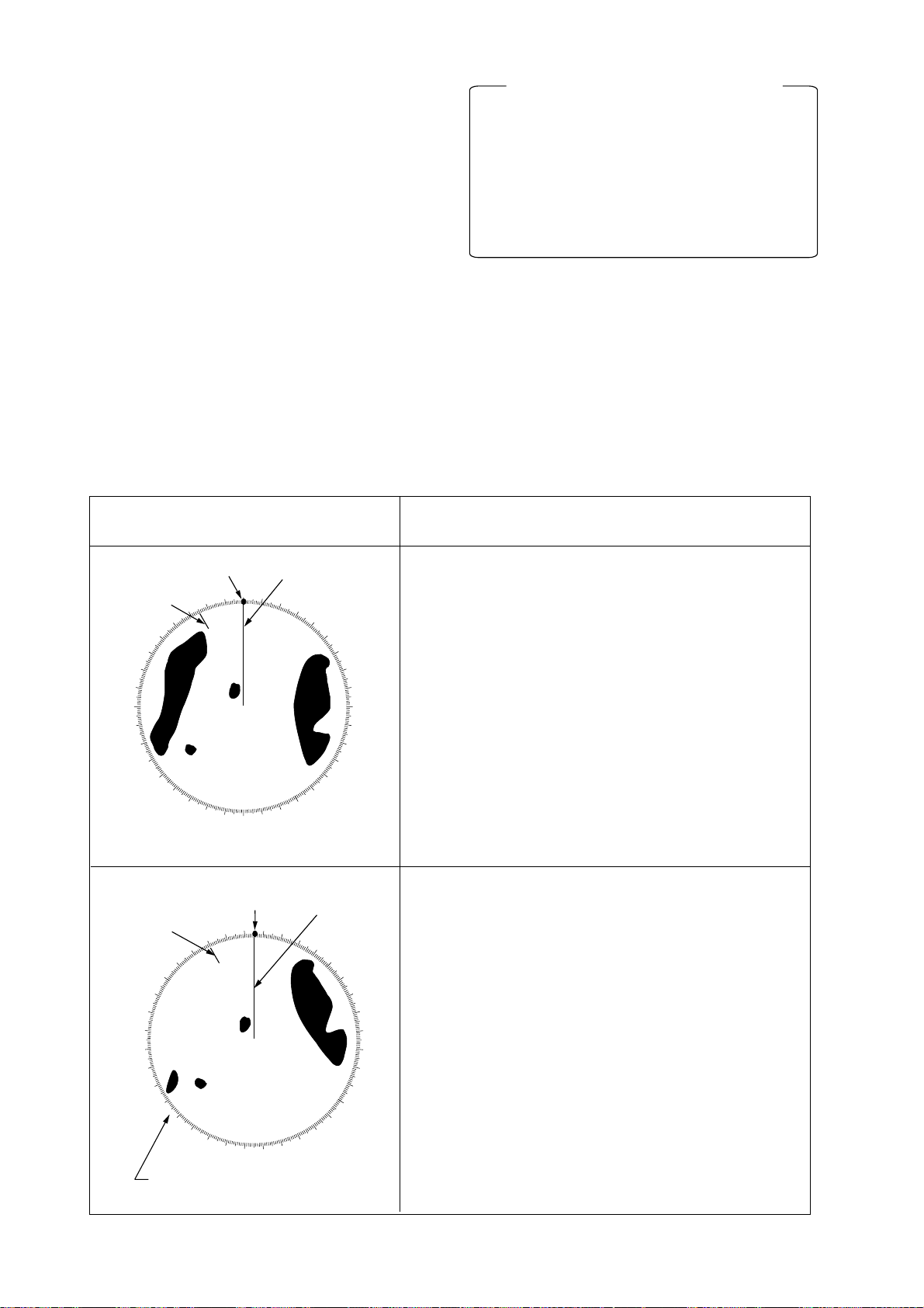
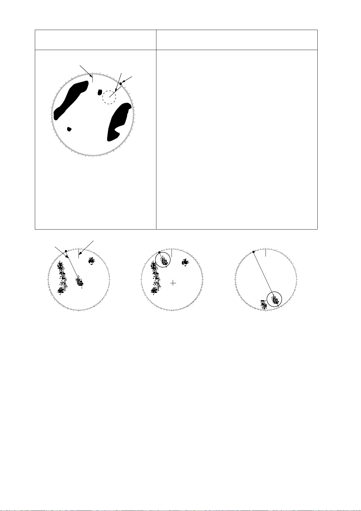
If relative motion is selected, it is also
possible to read CPA (Closest Point of
Approach) by using a VRM as shown in
Figure 1-17(a). If the EBL passes through
the sweep origin (own ship) as illustrated
Figure 1-17(b), the target ship is on a
collision course.
5. To return the EBL origin to the own ship
position, press the [EBL OFFSET] key
again.
Cursor
A
1
A
No.1
No.1
EBL
VRM
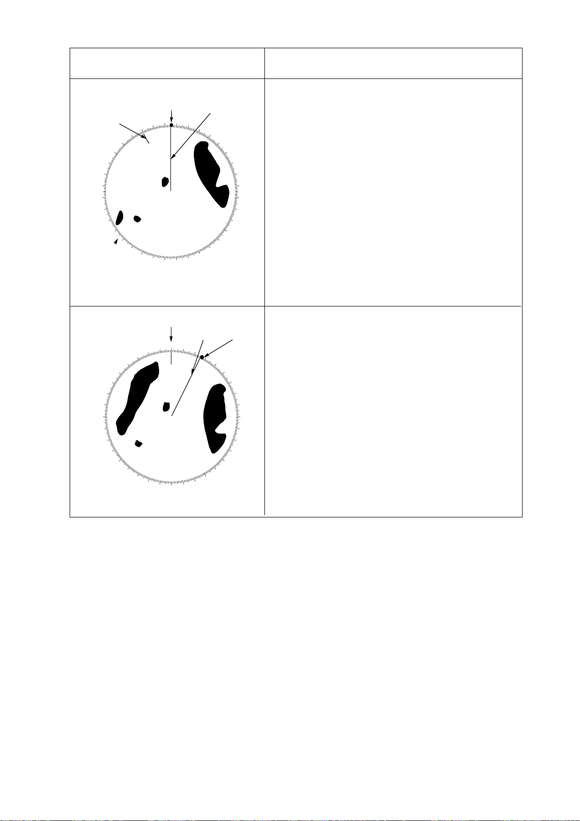
1.20 Collision Assessment by the Offset EBL
The origin of the EBL can be placed anywhere with the trackball to enable measurement of range and bearing between any
targets. This function is also useful for assessment of the potential risk of collision.
To assess possibility of collision:
1. Press the [EBL ON] key to display or activate EBL No.1.
2. Place the cursor (+) on a target of interest (A in the illustrated example) by operating the trackball.
3. Press the [EBL OFFSET] key, and the
origin of the active EBL shifts to the cursor position. Press the [EBL OFFSET] key
again to anchor the EBL origin.
4. After waiting for a few minutes (at least 3
minutes), operate the EBL rotary control
until the EBL bisects the target at the new
position (A ’). The EBL readout shows the
target ship’s course, which may be true
or relative depending on the settings on
the OTHER menu.
EBL
140.0°R
(a) Evaluating target ship’s course and
CPA in relative motion mode
Cursor
A
1
A
EBL
118.2°R
(b) Target ship on collision course
VRM
3.85NM
VRM
0.00nm
No.1
EBL
Figure 1-17 How to assess risk of collision
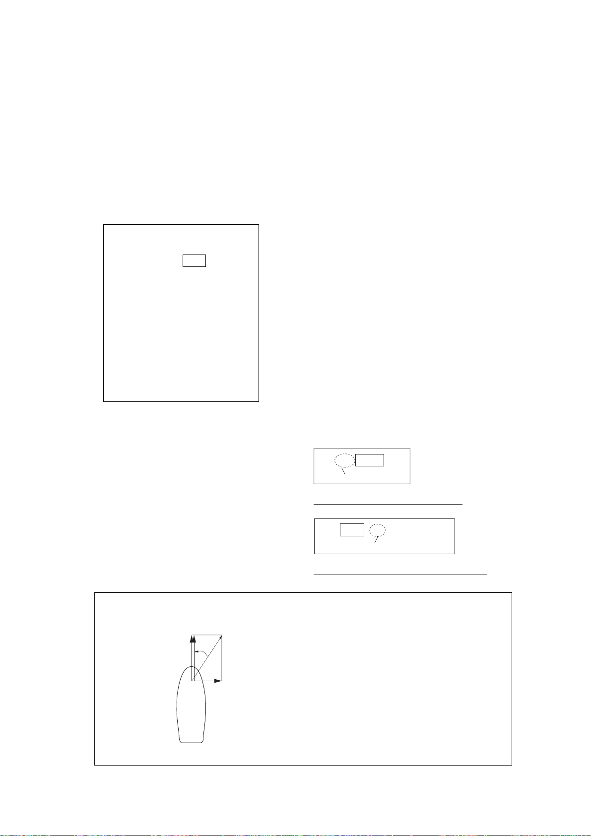
1.21 Measuring Range and Bearing Between Two Targets
1. Press the [EBL ON] key to activate the
No. 1 EBL. Press the [EBL OFFSET] key ,
and place the origin of the No.1 EBL on a
target of interest (target 1 in Figure 1-18)
by operating the trackball.
2. Turn the EBL rotary control until the EBL
passes through another target of interest
(target 2 in Figure 1-18).
1-15
Page 30

3. Turn the VRM rotary control until the
range marker on the No. 1 EBL aligns with
target 2 in Figure 1-18. The active VRM
readout at the lower-right corner of the
screen indicates the distance between the
two targets.
4. To return the EBL origin to the own ship
position, press the [EBL OFFSET] key
again.
Note: The target alarm is given to targets
having a certain level of echo strength. This
level does not always imply a landmass, reef,
ships or other surface objects but can mean
returns from the sea surface or precipitation.
Properly adjust the GAIN, A/C SEA, and A/C
RAIN controls to reduce noise to avoid generation of the guard alarm against false targets.
You can repeat the same procedure on third
and fourth targets by using the No.2 EBL and
No.2 VRM.
Bearing is shown relative to own ship with
suffix “R” or as a true bearing with suffix “T”
depending on EBL relative/true settings on
the OTHER menu.
A
EBL
80.0 R
Bearing from target A
to target B
B
Range between
target A and
target B
No. 1 EBL
No. 1 VRM
VRM
0.50NM
Figure 1-18 Measuring range and bearing
between two targets
The zone has a fixed width of 0.5 nm in the
radial direction (depth) and is adjustable only
within 3.0 to 6.0 nm from own ship. The outer
and inner boundaries can be set at any distance. The sector of the zone can be set anywhere between 0 and 360 degrees in any
direction.
To set target alarm zones:
1. Press the [MENU] key.
2. Press the [3] key twice to show the TGT
ALARM menu.
TGT ALARM
1. AREA NO1 NO2
2. MODE1 IN OUT
3. MODE2 IN OUT
Figure 1-19 TGT ALARM menu
2. Press the [1] key to select target alarm
zone to use; NO1 or NO2.
1.22 Setting a Target Alarm Zone
CAUTION
The target alarm feature should never be
relied upon as the sole means for detecting
the risk of potential collision. The operator
of a ship is not relieved of the responsibility
to keep lookout for avoiding collisions,
whether or not the radar is in use.
The target alarm serves to alert the navigator to targets (ships, landmasses, etc.) entering a certain area, with visual and audible
alarms.
3. Press the [ENTER/SELECT] key.
4. Press the [MENU] key.
5. Place the cursor (+) at point “A” (see figure below) using the trackball. Press the
[GZ ALARM] key. GZ1 (or GZ2) SET appears. When both alarms are prepared
the active alarm is circumscribed.
6. Move the cursor (+) to point “B” and press
the [GZ ALARM] key again. Then, an echo
watch zone as illustrated is created and
the label IN (or OUT) replaces SET at the
lower-right corner of the screen.
1-16
Page 31

Target alarm
zone
A
B
Figure 1-20 Target alarm
Note: If you wish to create a target alarm
zone having a 360-degree coverage around
own ship, set point “B” in almost the same
direction (approx. ±3°) as point “A” and press
the [GZ ALARM] key.
Two alarm zones can be set as described
above. To change the active alarm zone, do
steps 1 thru 4 in the above procedure. (When
both alarms are prepared the active alarm is
circumscribed.)
outward target alarm is produced when a target leaves the target alarm zone. (This is not
a target alarm by definition but some users
find this feature valuable.)
Dashed line: No alarm.
Alarm sounds when target
violates alarm setting.
Target alarm
zone
INWARD ALARM
OUTWARD ALARM
Figure 1-21 Inward and outward alarms
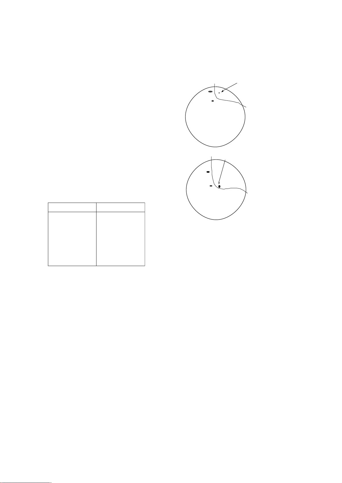
1.23 Off-centering (shift)
Own ship position, or sweep origin, can be
displaced to expand the view field without
switching to a larger range scale. The sweep
origin can be off-centered to a point specified by the cursor, up to 75% of ranges other
than 72, 96 and 120 nm.
Acknowledging alarm
A target entering the target alarm zone produces both visual (flashing) and audible
(beeping) alarms. To silence the audible
alarm, press the [AUDIO OFF] key shortly.
ACK replaces IN (or OUT).
This will deactivate the audible alarm but will
not stop the flashing of the target in the guard
alarm zone. To reactivate the audible alarm,
press the [GZ ALARM] key again.
To silence the audible alarm, you may press
the [AUDIO OFF] key . However , in this case,
the label ACK does not appear.
Deactivating target alarm zone
Hold the [GZ ALARM] key depressed for at
least 5 seconds.
This feature is not available on the longest
range scale or in the true motion mode. The
number of range rings increases keeping the
original range intervals unchanged.
To off center the radar picture:
1. Place the cursor at a position where you
wish to move the sweep origin by operating the trackball.
2. Press the [SHIFT] key. Then, the sweep
origin is off-centered to the cursor position. However, the heading line is left in
the same position.
3. To cancel of f-centering, press the [SHIFT]
key again.
Cursor
Cursor
Inward and outward alarms
The inward target alarm generates visual and
audible warnings when a target enters the
target alarm zone from any direction. The
(a) Select location
with cursor.
(b) Press SHIFT
key to offcenter.
Figure 1-22 Off-centered display
1-17
Page 32

Note: The display is automatically shifted by
75% of the range in use whenever the cursor is placed at an edge of the effective display area.
1.24 Echo Averaging
The echo average feature effectively suppresses sea clutter. Echoes received from
stable targets such as ships appear on the
screen at almost the same position every rotation of the scanner. On the other hand, unstable echoes such as sea clutter appear at
random positions.
To distinguish real target echoes from sea
clutter , echo average performs scan-to-scan
correlation. Correlation is made by storing
and averaging echo signals over successive
picture frames. If an echo is solid and stable,
it is presented in its normal intensity . Sea clutter is averaged over successive scans resulting in the reduced brilliance, making it easier
to discriminate real targets from sea clutter.
To properly use the echo average function, it
is recommended to first suppress sea clutter
with the A/C SEA control and then do the following:
1. Press the [MENU] key.
2. Press the [5] key twice to select the ECHO
SIG menu.
ECHO SIG
1. TGT COLOR YEL GRN COLOR
2. ECHO AVG OFF 0.5 1 2 3
3. INT REJ OFF 1 2 3
4. N REJ OFF ON
5. ENHANCE OFF ON
6. 2ND ECHO OFF ON
7. CONTRAST 1 2 3
8. CLTR SWEEP OFF ON(LINK) ON(FIX)
9. SWEEP LVL 1 2 3
0. CNTR ENHANCE OFF ON
3. Press the [2] key to select echo averaging level (OFF, 0.5 1, 2, 3) from the ECHO
AVG field.
OFF: No averaging effect
0.5: Distinguishes small targets from
sea clutter.
1: Distinguishes targets from sea
clutter and suppresses brilliance
of unstable echoes.
2: Distinguishes small stationary
targets such as navigation buoys.
3: Stably displays distant targets.
4. Press the [ENTER/SELECT] key to conclude your selection followed by the
[MENU] key to close the menu.
(a) Echo average OFF (b) Echo average ON
Figure 1-24 Echo averaging
Echo averaging uses scan-to-scan signal correlation technique based on the true motion
over the ground of each target. Thus, small
stationary targets such as buoys will be
shown while suppressing random echoes
such as sea clutter. True echo average is not
however effective for picking up small targets
running at high speeds over the ground.
Echo average requires log and compass signals. If you wish to use this feature without a
compass signal, consult a FURUNO representative.
Manual speed entry is done at the menu item
MAN SPD on the OTHER menu, which is accessed by pressing the [MENU] and [0]
(twice) keys.
1-18
Figure 1-23 ECHO SIG menu
Page 33

1.25 Electronic Plotting Aid (EPA)
Plotting a target
10 operator-selected targets can be plotted
electronically to assess their motion trend.
Five past positions can be displayed for each
of the plotted targets. If you enter a 6th plot
on a certain target, the oldest plot (past position) will be erased.
A vector appears when you enter a second
plot for the target and is updated each time a
new plot is entered. The vector shows the
target motion trend based on its latest two
plots.
T arget data is shown in the data display area
which shows range, bearing, course, speed,
CP A and TCP A of the last-plotted or selected
target.
Target data
000
010
350
320
310
See note
300
below.
290
280
See note
270
below.
260
250
Echo Watch Zone
240
230
220
340
330
210
200
020
030
040
1
2
3
140
150
160
190
170
180
050
120
130
060
070
080
090
100
110
TRUE VECTOR
30sec
EPA symbols
: Target plotted
: Target plotted and data
indicated.
: Target on a collision course
Note:
Target 2 is on a collision course as the extension
of its vector goes through the own ship position.
Placing the offset EBL will help for assessment.
TCPA is counted up to 99.59 min and beyond
that it is indicated as TCPA > 99.59 MIN.
1
Plotting time
RNG
BRG
CRS
SPD
CPA
TPCA
00:25
Figure 1-25 EPA display
Note: The EPA requires speed input (automatic or manual) and a compass signal. The
vector and data are updated on real time between plot entries, but do not neglect to plot
a new position over a long period of time.
Otherwise, the accuracy will be reduced. Note
that the plots will be lost when the compass
fails; start the plotting exercise again.
1. Place the cursor on a target of interest by
operating the trackball.
2. Press the [ACQ] key . A plot symbol (circle)
and target number (0-9) appears on the
target.
3. Watching the EP A time shown at the right
side of the screen, wait for at least 30
seconds. Place the cursor (+) on the plot
symbol with number and then press the
[ENTER/SELECT] key . The symbol shape
changes from circle to square and the
target number in the data display flashes.
4. While the target number is flashing, place
the cursor on the target and press the
[ACQ] key . The plot symbol moves to the
new target position and the previous position is marked by a small dot.
5. T o acquire other targets, repeat the above
steps selecting different plot symbols.
6. If the target echo separates from its plot
symbol, repeat steps 3 an 4.
Note: If a target once plotted is not plotted
again within 10 minutes, the warning “UPDATE PLOT” and Plot No. will appear on the
upper right margin of the screen and the plot
symbol of the target flashes. If you want to
continue plotting this target, reacquire it within
five minutes. Otherwise, the target will be regarded as a “lost target” and its plot symbol
and target data will be erased. The larger the
plotting interval, the less accurate the plotted target data. Plotting of each target should
normally be made every 3 or 6 minutes as
far as possible. You can use the Time Alarm
to warn yourself every 3 or 6 minutes.
Within 30 seconds, you can cancel a last plot
by the [CANCEL/CLEAR] key and make a
re-entry at a different position. After 30 seconds, the last entry is processed to produce
a vector.
1-19
Page 34

True or relative vector, vector time
Target data
Vectors can be displayed relative to own
ship’s heading (Relative) or with reference
to the North (True). This feature is available
in all presentation modes (compass must be
working correctly). The current vector mode
is indicated at the upper-right corner of the
screen.
Vector time (or the length of vectors) can be
set to 30 seconds, 1, 3, 6, 15 or 30 minutes
and the selected vector time is indicated at
the upper-right corner of the screen.
1. Press the [MENU] key followed by the [7]
key twice to select PLOT.
PLOT MENU 1
1. MARK DISP OFF ON
2. ERASE
3. VEC REF REL TRUE
4. VEC TIME 30S 1M 3M 6M
15M 30M
5. CPA SET OFF 0.5NM 1NM 1.5NM
2NM 3NM 4NM
5NM 6NM
6. TCPA SET 30S 1M 2M 3M
4M 5M 6M 12M 15M
7. TRACK OFF ON
8. AUDIO ALARM OFF ON
9. INTVAL* 30S 1M 2M 3M 6M
0. ↓*
* Requires ATA Board ARP-17.
The radar calculates motion trends (range,
bearing, course, speed, CPA and TCPA) of
all plotted targets.
In the head-up and head-up true bearing
modes, target bearing, course and speed
shown in the upper-right target data field become true (T) relative to north. The target data
field always displays true bearing, true course
and speed over the ground.
Reading the target data
Place the cursor on a plotted target and press
the [ENTER/SELECT] key . Then, the following target data is displayed at the right side
of the CRT.
RNG/BRG (Range/Bearing): Range and
bearing from own ship to last-plotted target
with suffix “T” (True).
CSE/SPD (Course/Speed): Course and
speed are displayed for the last-plotted target with suffix “T” (True).
CP A/TCPA: CPA (Closest Point of Approach)
is the closest range the target will approach
to own ship. TCPA is the time to CPA. Both
CP A and TCPA are automatically calculated.
TCPA is counted up to 99.59 min and beyond that it is indicated as TCPA > *99.59
MIN.
Figure 1-26 PLOT menu
2. Press the [3] key to select REL or TRUE
from the VECT REF field as appropriate,
and then press the [ENTER/SELECT]
key.
3. Press the [4] to select appropriate vector
time from the VEC TIME field, and then
press the [ENTER/SELECT] key.
4. Press the [MENU] key to close the menu.
The vector tip shows an estimated position
of the target after the selected vector time
elapses. It can be valuable to extend the vector length to evaluate the risk of collision with
any target.
1-20
Terminating target plotting
With the EPA you can plot up to 10 targets.
You may wish to terminate plotting of less
important targets to newly plot other threatening targets.
With Trackball: Place the cursor (+) on a
target which you do not want to be tracked
any longer by operating the trackball and
press the [CANCEL/CLEAR] key.
All Targets: To terminate plotting of all targets at once:
1. Press the [MENU] key followed by the [7]
key twice.
Page 35

2. Press the [2] key twice to select OFF from
the ERASE field.
3. Press the [ENTER/SELECT] key followed
by the [MENU] key.
Setting CPA/TCPA alarm ranges
When the predicted CPA of any target becomes smaller than a preset CP A alarm range
and its predicted TCPA less than a preset
TCPA alarm limit, the EPA releases an audible alarm and displays the warning label
COLLISION appears on the screen. In addition, the EPA symbol changes to a triangle
and flashes together with its vector.
PLOT MENU 1
1. MARK DISP OFF ON
2. ERASE
3. VEC REF REL TRUE
4. VEC TIME 30S 1M 3M 6M
15M 30M
5. CPA SET OFF 0.5NM 1NM 1.5NM
2NM 3NM 4NM
5NM 6NM
6. TCPA SET 30S 1M 2M 3M
4M 5M 6M 12M 15M
7. TRACK OFF ON
8. AUDIO ALARM OFF ON
9. INTVAL* 30S 1M 2M 3M 6M
0. ↓*
* Requires ATA Board ARP-17.
Provided that this feature is used correctly , it
will help prevent the risk of collision by alerting you to threatening targets. It is important
that GAIN, A/C SEA, A/C RAIN and other
radar controls are properly adjusted.
CP A/TCP A alarm ranges must be set up properly taking into consideration the size, tonnage, speed, turning performance and other
characteristics of own ship.
CAUTION
CPA/TCPA Alarm
The CPA/TCPA alarm feature should never
be relied upon as the sole means for detecting the risk of collision.
The navigator is not relieved of the responsibillity to keep visual lookout for avoiding
collisions, whether or not the radar or other
plotting aid is in use.
Figure 1-27 PLOT menu
3. Press the [5] key for CPA SET or [6] key
for TCPA set.
4. Press the [5] key or [6] key again to select CPA or TCPA range desired.
5. Press the [ENTER/SELECT] key to register your selection.
6. Press the [MENU] key to close the menu.
Silencing CPA/TCPA audible alarm
Press the [AUDIO OFF] key to acknowledge
and silence the CPA/TCPA aural alarm.
The flashing of the triangle plot symbol and
vector remain on the screen until the dangerous situation is gone or you intentionally
terminate tracking of the target by using the
trackball.
To set the CPA/TCPA alarm ranges:
1. Press the [MENU] key.
2. Press the [7] key twice to display the
PLOT menu.
Lost target alarm
When the system detects a lost target, tracking on the target is discontinued and the target symbol becomes a flashing diamond. The
normal plotting symbol is restored to the target when the target is manually acquired. If
not reacquired the flashing diamond is automatically erased. To confirm a lost target,
place the cursor on it and press the [CANCEL/CLEAR] key.
1-21
Page 36

Past plot points
Past plot points may be marked on the display with as many as nine dots. Y ou can turn
this display on/off as follows:
1. Press the [MENU] key.
2. Press the [7] key twice to select PLOT.
PLOT MENU 1
1. MARK DISP OFF ON
2. ERASE
3. VEC REF REL TRUE
4. VEC TIME 30S 1M 3M 6M
15M 30M
5. CPA SET OFF 0.5NM 1NM 1.5NM
2NM 3NM 4NM
5NM 6NM
6. TCPA SET 30S 1M 2M 3M
4M 5M 6M 12M 15M
7. TRACK OFF ON
8. AUDIO ALARM OFF ON
9. INTVAL* 30S 1M 2M 3M 6M
0. ↓*
* Requires ATA Board ARP-17.
Figure 1-28 PLOT menu
3. Press the [7] key to select OFF or ON from
the TRACK field as appropriate.
4. Press the [ENTER/SELECT] key to register your selection followed by the
[MENU] key to close the menu.
ments in accordance with their over-theground speeds and courses.
a) True target trails-no smearing
of stationary targets
b) Relative target trails-all targets
moving relative to own ship
Figure 1-29 Target trails
Note: When relative trail on the TM mode,
the legend REL TRAIL appears in red.
To select true or relative target trail presentation:
1. Press the [MENU] key.
1.26 Target Trails (Echo Trails)
It is possible to display the trails of the radar
echoes of targets in the form of synthetic afterglow. Target trails are selected either relative or true and may be sea or ground
stabilized. The simulated afterglow can be selected in a single tone or gradual shading depending on a setting on the TGT TRAIL menu.
Note that afterglow is shown in light yellow
when the echo color is green.
True or relative trails
Y ou may display target trails relative to north
or own ship heading in Relative Motion. True
motion trails require a compass signal and
own ship speed input to cancel out own ship’s
movement and present true target move-
2. Press the [2] key twice to show the TGT
TRAIL menu.
TGT TRAIL
1. TIME 15S 30S 1M 3M
6M 15M 30M CONT
2. MODE REL TRUE
3. SHADE MONO MULTI
4. LEVEL 1 2 3
5. TRAIL COPY OFF ON
6. THIN TRAIL OFF ON
7. THIN MODE 1 2 3 4
Figure 1-30 TGT TRAIL menu
3. Press the [2] key several times to select
REL or TRUE from the MODE field as
appropriate.
1-22
Page 37

4. Press the [ENTER/SELECT] key to confirm your selection, then the [MENU] key
to close the menu.
Trail gradation
Selecting trail time
1. Press the [MENU] key.
2. Press the [2] key twice to select TGT
TRAIL.
Target trails may be shown in monotone or
multitone. Gradual shading paints the trails
getting thinner with time just like the afterglow on an analog PPI radar.
Monotone
(Single)
Gradual shading
(Multi)
Figure 1-31 Monotone and multitone
target trails
1. Press the [MENU] key.
2. Press the [2] key twice to select TGT
TRAIL.
TGT TRAIL
1. TIME 15S 30S 1M 3M
6M 15M 30M CONT
2. MODE REL TRUE
3. SHADE MONO MULTI
4. LEVEL 1 2 3
5. TRAIL COPY OFF ON
6. THIN TRAIL OFF ON
7. THIN MODE 1 2 3 4
Figure 1-32 TGT TRAIL menu
3. Press the [3] key to select MONO or
MULTI from the SHADE field as appropriate.
4. Press the [ENTER/SELECT] key and the
[MENU] key in order.
TGT TRAIL
1. TIME 15S 30S 1M 3M
6M 15M 30M CONT
2. MODE REL TRUE
3. SHADE MONO MULTI
4. LEVEL 1 2 3
5. TRAIL COPY OFF ON
6. THIN TRAIL OFF ON
7. THIN MODE 1 2 3 4
Figure 1-33 TGT TRAIL menu
3. Press the [1] key to select time desired
from the TIME field.
4. Press the [ENTER/SELECT] key and the
[MENU] key in order.
Restoring trails
Trails are cancelled and restarted whenever
the range is changed. However, you can continue trails on the same range, without restarting, when the range is changed to a next
larger or smaller range scale. Note however
that when the range is changed, only those
target trails within the previous range are
continued; no trails are generated for targets
outside of the previous range.
No trail generated
for target not within
previous range
Displaying, erasing target trails
Press the [TGT TRAIL] key to activate or deactivate the target trails feature. The current
target trail setting is displayed at the upper
right-and corner of the screen.
To remove trails from the screen, press the
[TGT TRAIL] with a hit-and-release action.
(Trailing continues off screen with target trail
timer counting). Press the key again to
redisplay the trails.
(a) Previous range
(b) New range
Figure 1-34 How trail copy works
1. Press the [MENU] key.
2. Press the [2] key twice to select TGT
TRAIL.
1-23
Page 38

3. Press the [5] key to select ON or OFF from
the TRAIL COPY field as appropriate.
4. Press the [ENTER/SELECT] key and
[MENU] key in order.
Thin trails
T arget trails may be painted with thinner lines
if desired. This can be useful when there are
a lot of targets on the screen.
Resetting target trails
T o reset (or clear) the target trail memory , hold
the [TGT TRAIL] key depressed for about 3
seconds. Target trails are cleared and the
trailing process restarts from time count zero
at current target trail plot interval. Note that
target trails are also restarted when the shift
feature is turned on or the range is changed.
Trail brilliance
The brilliance of target trails can be adjusted
on the BRILL menu as follows:
1. Press the [MENU] key.
2. Press the [9] key twice to display the
BRILL menu.
BRILL
1. TGT TRAIL
2. CHARACTER
3. HDG LINE
4. EBL/VRM
5. CURSOR
6. MARK
7. PLOT
8. OS SYMB
9. ↓*
* Requires RP-17 Board.
1. Press the [MENU] key.
2. Press the [2] key twice to select TGT
TRAIL.
3. Press the [6] key to show THIN TRAIL ON
or OFF as appropriate.
4. Press the [7] key to select 1, 2, 3 or 4 as
appropriate. When there are a lot of targets on the screen, select a larger number (for thinner trails); select a smaller
number when there are few targets. The
default setting is 1.
5. Press the [ENTER/SELECT] key and
[MENU] key in order.
Trail afterglow
The strength of the synthetic afterglow to remain on the display may be selected as follows:
1. Press the [MENU] key.
2. Press the [2] key twice to select TGT
TRAIL.
3. Press the [4] key to select desired level
from the LEVEL field; “3” displays only the
highest level of afterglow.
4. Press the [ENTER/SELECT] key and
[MENU] key in order.
Figure 1-35 BRILL menu
3. Press the [1] key twice to select TGT
TRAIL.
4. Operate the VRM rotary control to adjust
brilliance. Current brilliance is shown by
the BRILL bar graph at the top right-hand
corner of the screen.
5. Press the [ENTER/SELECT] key to conclude your selection followed by the
[MENU] key to close the menu.
1-24
Page 39

1.27 Parallel Index Lines
To use the origin mark:
Parallel index lines are useful for keeping a
constant distance between own ship and a
coastline or a partner ship when navigating.
The orientation of the index lines is controlled
with the EBL rotary control and the intervals
between the lines adjusted with the VRM rotary control (provided that No.2 VRM is active).
Index lines
Figure 1-36 Index lines
Displaying/erasing the index lines
Press the [INDEX LINE] key to display/erase
the index lines. Each press of the key turns
the parallel index lines on (enabling adjustment by VRM, EBL), fixes them on the display or turns them off.
1. Place the cursor (+) at a point where you
want to place a reference mark by operating the trackball.
2. Press the [MARK] key. The origin mark
appears at the cursor position, of which
range and bearing are indicated at the
upper-right section of the screen.
Origin mark reference
The origin mark can be set relative to own
ship (relative), or referenced to land (sea or
ground stabilized).
1. Press the [MENU] key.
2. Press the [8] key twice to select MARK.
MARK
1. ERASE
2. MODE REL TRUE
Figure 1-37 MARK menu
3. Press the [2] to select the REL or TRUE
from the MODE field as appropriate.
4. Press the [ENTER/SELECT] key.
5. Press the [MENU] key.
Selecting number of index lines to
display
Maximum number of the index lines can be
set for 2 or 6 on the MARK/LINE in the
OTHER menu.
1.28 Origin Mark
You can mark any reference points, prominent target or a point of particular interest using the origin mark feature. This mark is
geographically fixed, namely, ground stabilized. Twenty such origin marks can be entered. This function is not available when the
RP-17 board is installed.
Erasing origin marks
Erasing individual origin marks
Select the origin mark with the cursor and
then press the [CANCEL/CLEAR] key.
Erasing all origin marks
1. Press the [MENU] key.
2. Press the [8] key twice to select MARK.
3. Press the [1] key twice.
4. Press the [MENU] key.
1-25
Page 40

1.29 Zoom
The zoom function is useful for enlarging an
area of interest as large as twice the normal
viewing. This performs the range scale reduction to a half and the offset at the same
time. Zoom can be used on ranges other than
0.125, 72, 96, 120 nm.
1. Place the cursor (+) close to the point of
interest by operating the trackball.
2. Press the [ZOOM] key. The area around
the cursor and own ship is enlarged twice
as large as the original size.
3. T o cancel zoom, press and hold down the
[ZOOM] key about two seconds.
Note: The zoom feature is inoperative when
the display is off centered.
+
Cursor
+
Cursor
Temporarily erasing heading line, north
marker, stern marker, own ship symbol
To temporarily extinguish the heading line,
north marker, stern marker and own ship symbol to look at a target which may be obscured
by those markers, press the GAIN control (HL
OFF control). The heading line, north marker ,
stern marker and own ship symbol reappear
when the control is released. Note that the
RP screen is also temporarily erased when
the RP-17 is connected.
North marker
The north marker appears as a short dashed
line. In the head-up mode, the north marker
moves around the bearing scale in accordance with the compass signal.
Stern marker
The stern marker (a dot-and-dash line) appears opposite to the heading line. It can be
displayed/erased on the item MARK/LINE in
the OTHER menu.
(a) Cursor placed at
point of interest
Figure 1-38 Zoom
(b) Press ZOOM
key to zoom in.
1.30 Markers
Heading line
The heading line indicates the ship’s heading in all presentation modes, and is a line
from the own ship position to the outer edge
of the radar display area and appears at zero
degrees on the bearing scale in head-up
mode, it changes the orientation depending
on the ship orientation in the north-up and
true motion modes.
Own ship symbol
The own ship symbol appears at own ship
position. It can be displayed/erased on the
item MARK/LINE in the OTHER menu. The
symbol is scaled to indicate length and beam
of the vessel. If the largest dimension of the
symbol gets smaller than 6 nm, the symbol
will disappear and own ship will be represented by a small dot or circle. The size of
the symbol is set at installation.
1-26
Page 41

1.31 User Keys (F1, F2, F3)
The user keys [F1], [F2] and [F3] may be programmed by the operator to display a desired
menu. For example, you can program the [F2]
key to select target trail time whenever the
key is pressed.
The default settings are [F1], echo averaging; [F2], echo stretch and [F3], clutter sweep.
Presetting the user keys
4. Select desired function with the VRM rotary control.
5. Press the [ENTER/SELECT] key to register your selection, and then press the
[MENU] key to finish.
Activating a user-defined key
Press a user key. Press the key again to select option desired.
1. Press the [MENU] key.
2. Press the [6] key twice to display the
FUNC menu.
FUNC
1. FUNC1
2. FUNC2
3. F•1
4. F•2
5. F•3
6. A/D CURVE A B C D
Figure 1-39 FUNC menu
3. Press [3], [4], or [5] key twice depending
on which user key you want to set. For
example, press the [4] key to program the
[F2] key.
[F•2 MENU]
1. TRAIL TIME 26. HUTB MODE
2. TRAIL MODE 27. TUNE A/M
3. TRAIL SHADE 28. EXT WP
4. TRAIL LEVEL 29. OS POSN
5. ALARM AREA 30. CURS BRG
6. ALARM MODE 31. EBL1 T/R
7. PANEL DIMMER 32. EBL2 T/R
8. TGT COLOR 33. CURS RNG
9. ECHO AVG 34. VRM1 RNG
10. INT REJ 35. VRM2 RNG
11. ECHO STRETCH 36. CLTR SWEEP
12. NOISE REJ 37. MARK MENU
13. ECHO ENHANCE 38. DISP MODE
14. 2ND ECHO 39. A/D CURVE
15. CONTRAST 40. ORIGIN MARK
16. PLOT MENU 41. DEST ON CSR
17. MARK MODE
18. BRILL MENU
19. DRIFT MENU
20. NAV DATA
21. DISPLAY
22. SART
23. TIME ALARM
24. STERN MARK
25. OS MARK
Select by VRM knob
and hit ENTER key.
37 and 38 shown with connection of RP-17.
1.32 Function Keys
The function keys work similar to the automatic dialing feature on a telephone, playing
back control settings just as they were registered. Instead of manually adjusting controls
to set up for a particular condition, for example, navigation in a harbor, you can have
a function key do it for you.
Each function key can be assigned a combination of particular radar settings that will be
most suited to a specPic navigation purpose,
and an adhesive-backed label (such as
OCEAN, COAST) is usually attached to the
keytop for easy identification of the assigned
purpose.
Presetting the function keys
The radar’s internal computer offers several
navigation setups as outlined in the table on
the next page. For instance, you might want
to select RAIN as the objective of a function
key. Then, when you press that function key
the radar will be instantly set up to operate
under heavy rain conditions.
Each setup option defines a combination of
several radar settings for achieving optimum
setup for a particular navigating situation.
Those involved are interference rejector, echo
stretch, echo average, automatic anti-clutter,
noise rejector, video contrast, and enhanced
video.
Figure 1-40 Function menu
1-27
Page 42

Adjusting these features on a function key
menu changes the original function key settings. To restore the original settings for a
particular function key , it is necessary to display the relevant function key menu and select appropriate menu options.
Table 1-2 FUNC key objectives
lebaLnoitpircseD
TSAOCegnartrohsrofgnittesmumitpO
elacsegnaragnisunoitceted
mlacnomn6dna5.1neewteb
.saes
NAECOegnargnolrofgnittesmumitpO
elacsegnaragnisunoitceted
.mn42dna6neewteb
AES-RsaesyvaehrofgnittesmumitpO
3neewtebelacsegnaragnsu
.mn21dna
NIARniaryvaehrofgnittesmumitpO
elacsegnaragnisusnoitidnoc
.mn42dna6neewteb
N-DRIBgnitcetedrofgnittesmumitpO
elacsegnaragnisusdrib
.mn8dna3neewteb
F-DRIBgnitcetedrofgnittesmumitpO
elacsegnaragnisusdrib
.mn42dna61neewteb
1. Press the [MENU] key followed by the [6]
key twice to display the FUNC menu.
2. Press [1] or [2] key twice to select function to program. For example, press the
[1] key to program FUNC1. The following
menu appears.
FUNC 1 MENU
1. ↑
2. FUNC SEL COAST OCEAN
R-SEA RAIN
BIRD-N BIRD-F
3. ECHO AVG OFF 0.5 1 2 3
4. INT REJ OFF 1 2 3
5. STRETCH OFF 1 2
6. N REJ OFF ON
7. ENHANCE OFF ON
8. CONTRAST OFF 1 2 3
9. A/C AUTO OFF ON
Figure 1-42 FUNC1 menu
3. Press the [2] key twice to select function
desired.
4. Change other functions (echo avg, int rej,
etc.) if necessary.
5. Press the [ENTER/SELECT] key to register your selection followed by the
[MENU] key to close the menu.
FUNC
1. FUNC1
2. FUNC2
3. F•1
4. F•2
5. F•3
6. A/D CURVE A B C D
Figure 1-41 FUNC menu
Table 1-3 Default function key settings
sgnitteSyeKnoitcnuFtluafeD
lebaLOHCE.3
GVA
TSAOC11FFOFFOFFO2FFO
NAECO11FFOFFOFFO2FFO
AES-R21FFOFFOFFO2NO
NIAR5.01 FFOFFOFFO2FFO
N-DRIB21FFONOFFO2FFO
F-DRIB312NOFFO3FFO
TNI.4
JER
HCTERTS.5JERN.6ECNAHNE.7-NOC.8
TSART
C/A.9
OTU/A
1-28
Page 43

1.33 Suppressing Second-trace
1.34 Adjusting Brilliance of
Echoes
In certain situations, echoes from very distant targets may appear as false echoes (second-trace echoes) on the screen. This occurs
when the return echo is received one transmission cycle later, that is, after a next radar
pulse has been transmitted.
To activate or deactivate the second-trace
echo rejector:
1. Press the [MENU] key followed by the [5]
key twice to display the ECHO SIG menu.
ECHO SIG
1. TGT COLOR YEL GRN COLOR
2. ECHO AVG OFF 0.5 1 2 3
3. INT REJ OFF 1 2 3
4. N REJ OFF ON
5. ENHANCE OFF ON
6. 2ND ECHO OFF ON
7. CONTRAST 1 2 3
8. CLTR SWEEP OFF ON(LINK) ON(FIX)
9. SWEEP LVL 1 2 3
0. CNTR ENHANCE OFF ON
Figure 1-43 ECHO SIG menu
Screen Data
You can adjust relative brilliance levels of
various marks and alphanumeric readouts
displayed on the screen as follows:
1. Press the [MENU] key.
2. Press the [9] key twice to show the BRILL
menu.
BRILL
1. TGT TRAIL
2. CHARACTER
3. HDG LINE
4. EBL/VRM
5. CURSOR
6. MARK
7. PLOT
8. OS SYMB
9. ↓*
* Requires RP-17 Board.
Figure 1-44 BRILL menu
3. Press appropriate numeric key twice to
select item to adjust. For example, press
the [1] key if you want to change the brilliance of target trails.
2. Press the [6] key to select OFF or ON from
the 2ND ECHO field as appropriate.
3. Press the [ENTER/SELECT] key to conclude your selection followed by the
[MENU] key to close the menu.
4. Operate the VRM rotary control to adjust
brilliance. Current brilliance level is displayed on the selected item’s bar graph.
The adjustment range is as follows;
1. ECHO TRAIL: 10%-50%
2. CHARACTER, 3. HDG LINE: 50% 100%
4. EBL/VRM, 5. CURSOR, 6. MARK,
7. PLOT, 8. OS SYMB: 0%-100%
5. Press the [ENTER /SELECT] key to conclude your selection followed by the
[MENU] key to close the menu.
1-29
Page 44

1.35 Noise Rejector
The noise rejector suppresses white noise,
which appears on the screen as many dots
scattered randomly over the display.
To suppress white noise:
1. Press the [MENU] key.
2. Press the [2] key to select desired interval
(3, 6, 12, 15, 20 min) from the ALM INTVL
field.
3. Press the [ENTER/SELECT] key to conclude your selection followed by the
[MENU] key to close the menu.
2. Press the [5] key twice to show the ECHO
SIG menu.
ECHO SIG
1. TGT COLOR YEL GRN COLOR
2. ECHO AVG OFF 0.5 1 2 3
3. INT REJ OFF 1 2 3
4. N REJ OFF ON
5. ENHANCE OFF ON
6. 2ND ECHO OFF ON
7. CONTRAST 1 2 3
8. CLTR SWEEP OFF ON(LINK) ON(FIX)
9. SWEEP LVL 1 2 3
0. CNTR ENHANCE OFF ON
Figure 1-45 ECHO SIG menu
3. Press the [4] to select OFF or ON from
the N REJ field as appropriate.
4. Press the [ENTER/SELECT] key to conclude your selection followed by the
[MENU] key to close the menu.
1.36 Time Alarm
The time alarm gives an aural at a predetermined interval.
1.37 Enhanced Video
On long ranges target echoes tend to shrink
in the bearing direction, making them difficult
to see. On short and medium ranges such as
1.5, 3 and 6 nm scales, the same size targets
get smaller on screen as they approach the
own ship. These are due to the inherent property of the radiation pattern of the antenna.
To enhance target video, use the enhanced
video function. It enlarges target echoes in
bearing and range direction on 1.5-6 nm
scales.
1. Press the [MENU] key followed by the [5]
key twice to show the ECHO SIG menu.
ECHO SIG
1. TGT COLOR YEL GRN COLOR
2. ECHO AVG OFF 0.5 1 2 3
3. INT REJ OFF 1 2 3
4. N REJ OFF ON
5. ENHANCE OFF ON
6. 2ND ECHO OFF ON
7. CONTRAST 1 2 3
8. CLTR SWEEP OFF ON(LINK) ON(FIX)
9. SWEEP LVL 1 2 3
0. CNTR ENHANCE OFF ON
T o silence the alarm, press the [AUDIO OFF]
key. The label T-ALM turns to normal color
and the timer is reset to initial value and starts
the count-down sequence again.
To activate the time alarm:
1. Press [MENU], [0] twice and [4] twice to
display the TIME ALARM.
TIME ALARM
1. ↑
2. ALARM INTV OFF 3M 6M
12M 15M 20M
Figure 1-46 TIME ALARM menu
1-30
Figure 1-47 ECHO SIG menu
2. Press the [5] key to select OFF or ON from
the ENHANCE field.
3. Press the [ENTER/SELECT] key , and then
press the [MENU] key.
Page 45

Echo enlarged in bearing
and range directions
Figure 1-48 How the enhance
function works
Note: Enhanced video can also be selected
with a user key.
4. Press the [2] key to select desired degaussing interval (OFF , 1, 5, 10 min) from
the DEGS INTV field, and then press the
[ENTER/SELECT] key.
5. Press the [3] key to select desired degaussing degree (45°, 90°, 135°) from the
DEGS DEG field. For example, selecting
45° will automatically degauss the screen
when the ship makes a turn which is between 45° and 89°.
6. Press the [ENTER/SELECT] key followed
by the [MENU] key.
1.39 Navigation Data
1.38 Degaussing Interval
The screen is degaussed automatically at
certain time intervals, as well as each time
the radar is turned on, to demagnetize the
CRT screen to eliminate color contamination
caused by earth’s magnetism or magnetized
ship structure. You can select the degaussing interval and the degaussing degree as
follows:
1. Press the [MENU] key followed by the [0]
key twice to select OTHER.
2. Press the [0] key twice to select the
OTHER menu.
OTHER
1. ↑
2. TEST
3. DEGAUSS
4. TIME ALARM
5. RANGE
6. INSTALL
Various navigation data can be displayed
(and their format selected) with connection
of appropriate external sensors. You can select which navigation data to display as follows:
1. Press the [MENU] key, and then the [0]
key twice show the OTHER menu.
2. Press the [8] key twice to select display
the NAV DATA menu.
3. Press appropriate numeric key to turn
data on/off, select format, etc. Press the
[ENTER/SELECT] key after setting each
option. Water temperature and depth displays are off in the default setting.
Note 1: OFF in the OS POSN field simply
erases own ship position data; it does not
stop input of nav data from a navigation
device.
Note 2: TIME DIF selects time system to
use; UTC or LOCAL. UTC = Local + T ime
Dif.
Figure 1-49 OTHER menu
3. Press the [3] key twice to display the DEGAUSS menu.
DEGAUSS
1. ↑
2. DEGS INTV OFF 30S 1M 2M
3. DEGS DEG OFF 45° 90° 135°
Figure 1-50 DEGAUSS menu
4. Press the [MENU] key.
All navigation data may be turned on/off by
the keying sequence of [MENU], [0] (twice)
and [5].
1-31
Page 46

1.40 Video Contrast
The video contrast is adjustable in three levels according to the radar video sampling
level. Select the level so that the video contrast feature changes the dynamic range of
the video signal to improve picture contrast.
Picture shows up most clearly from the background.
1. Press the [MENU] key.
2. Press the [5] key twice to display the
ECHO SIG menu.
ECHO SIG
1. TGT COLOR YEL GRN COLOR
2. ECHO AVG OFF 0.5 1 2 3
3. INT REJ OFF 1 2 3
4. N REJ OFF ON
5. ENHANCE OFF ON
6. 2ND ECHO OFF ON
7. CONTRAST 1 2 3
8. CLTR SWEEP OFF ON(LINK) ON(FIX)
9. SWEEP LVL 1 2 3
0. CNTR ENHANCE OFF ON
3. Press the [8] key to turn on/off the clutter
sweep function, and then press the [ENTER/SELECT] key.
OFF: Turns off clutter sweep
feature.
ON(LINK): Sweep area moves with
trackball operation. Sweep
cursor shown by dashed
lines.
ON(FIX): Sweep area is fixed on the
screen. Sweep cursor
shown by solid lines.
4. Press the [9] key (SWEEP LVL) several
times to select level of suppression to use;
“3” provides the highest level of noise suppression.
5. Press the [ENTER/SELECT] key to register your selection and the [MENU] key
to finish.
6. Operate the trackball to select area to process.
Select area to
process with
square cursor.
Figure 1-51 ECHO SIG menu
3. Press the [7] key to select desired contrast level from the CONTRAST field.
4. Press the [ENTER/SELECT] key to register you selection and the [MENU] key
to finish.
1.41 Clutter Sweep
The clutter sweep feature suppresses sea
and rain clutters within the trackball-selected
area, to discriminate specific targets from
noise. The user may select the area to process and the level of suppression to apply
as follows:
1. Press the [MENU] key.
2. Press the [5] key twice to select the ECHO
SIG menu.
Figure 1-52 Selection of area to
process with clutter sweep
The clutter sweep feature may also be activated by a user key.
1.42 Outputting Target Position
Target position can be output (in IEC 611621 format) to a video plotter and marked on its
screen with a symbol. Select target with the
trackball and push the A/C RAIN control.
(TLL) This function requires position data and
compass signal.
1-32
Page 47

1.43 Background Color
3. Press the [5] key twice to select RANGE.
The secondary function of the BRILL control
(BKGND COLOR) is to select the color of the
background, characters, menu, markers and
indications, from the five color combinations
shown in the table below. Each press of the
control selects one of the five color combinations.
Table 1-4 Available color combinations
tnemegnarrA12345
aerA
yalpsiDradaR
aerAyalpsiD
sretcarahCNRGNRGNRGTHWDER
uneMLEYLEYLEYLEYDER
MRV/LBEULB-LNRGNRGNRGULB-L
sgniRegnaRNRGTHWTHWTHWNRG
rosruCTHWNRGNRGNRGTHW
eniLgnidaeHNRGTHWTHWTHWNRG
mralAtegraT
enoZ
rekraMhtroNTHWULB-LULB-LULB-LTHW
rekraMnretSTHWULB-LULB-LULB-LTHW
KLBULBULBULBKLB
radaRedistuO
KLBKLBKLBULBKLB
thgilhgiHuneMLEYLEYLEYLEYDER
THWULB-LULB-LULB-LTHW
wolleY,LEY,neerG,NRG
;etihW,THW;eulb-thgiL,ULB-L;eulB,ULB;kcalB,KLB
RANGE
1. ↑
2. RANGE 1/8 1/4 1/2
3/4 1 1.5 2 3
4 6 8 12 16
24 32 48 72 96 120
Figure 1-54 RANGE menu
4. Press the [2] key to place the underline
under the range scale to select/deselect
and then press the [ENTER/SELECT]
key . Active ranges are highlighted. Repeat
to select/deselect other ranges.
5. Press the [MENU] key.
1.45 Selecting Bearing Scale
Format
The bearing scale may be displayed in degrees or compass points or degrees as follows:
1. Press the [MENU] key.
2. Press the [0] key twice to display the
OTHER menu.
1.44 Selecting Range Scales
Range scales to use may be selected as follows:
1. Press the [MENU] key.
2. Press the [0] key four times to display the
OTHER sub menu.
OTHER
1. ↑
2. TEST
3. DEGAUSS
4. TIME ALARM
5. RANGE
6. INSTALL
Figure 1-53 OTHER sub menu
3. Press the [6] key twice to display the
MARK/LINE menu.
MARK/LINE
1. ↑
2. INDEX LINES 2 6
3. STERN MARK OFF ON
4. SHIP’S MARK OFF ON
5. BEARING SCALE 360 COMPASS
Figure 1-55 MARK/LINE menu
4. Press the [5] key to select 360 (degrees)
or COMPASS.
5. Press the [ENTER/SELECT] key to register your selection and the [MENU] key
to close the menu.
1-33
Page 48

1.46 A/D Converter Curve
1.47 Enlarging Close-in Targets
Setting
Video signal threshold level and color output
setting (for the CRT) are executed when the
video signal is converted from analog to digital. Select the A/D curve according to objective referring to the table below. The default
setting is A.
1. Press the [MENU] key.
2. Press the [6] key twice to display the
FUNC menu.
FUNC
1. FUNC1
2. FUNC2
3. F•1
4. F•2
5. F•3
6. A/D CURVE A B C D
The center enhance feature enlarges all echoes within the first range on any range.
1. Press the [MENU] key.
2. Press the [5] key twice to display the
ECHO SIG menu.
3. Press the [0] key to turn CNTR ENHANCE
on or off.
4. Press the [ENTER/SELECT] key followed
by the [MENU] key.
Figure 1-56 FUNC menu
3. Press the [6] key to select A/D curve setting, referring to the table below.
4. Press the [ENTER/SELECT] key followed
by the [MENU] key.
Table 1-5 A/D curve settings
tubneergfotolA
.derelttil
A
.roloc
B
C
D
.C
.derfotol
.derdna
.derfotol
nineergsiesioN
dnaAneewteB
tubneergelttiL
.esioneniF
wolleyniesioN
tubneergelttiL
.esioneniF
.derniesioN
Cnaht
noitcetedtaolF
snoitcelferaesecudeR
noitagivanlareneG
roflufesU:esulamroN
noitanimircsidtegrat
noitcetedegnargnoL
noitcetedyouB
noitcetedegnargnoL
noitcetedyouB
noitcetedegnarregnoL
1-34
Page 49

1.48 Alarms
The table below shows the alarm indications which appear on the display screen.
Table 1-6 Alarms
tluaFmralaelbiduAmralalausiVsutatsmralatiuqoT
eruliafgnidaeHspeebgnidaeHlebalsdaer
egassemehtdna"°x.xxx"
"GNISSIMLANGISORYG"
.dernisraeppa
yllacitamotuasiyalpsiD
edompu-daeHotdehctiws
nim1nihtiw.
tegraTmralaspeeB.sehsalftegraT.yek]MRALATGT[sserP
mralahctaWspeeB00:0HCTAW
snrut"MITHCTAW"lebaL(
sezeerftnuocemitdnader
.)".00:0"ta
nol/talpihsnwO
nol/talrosruC
eruliafmetsySenoNLANGISIZA"egasseM
tcerrocnI
ekortsyek
enoNnoitisoppihsnwoni"x.xxx"
dleif
noitisoprosrucni"x.xxx"
dleif
oN.sraeppa"GNISSIM
.seohceradar
enotpeebelbuoDenoNdednopsersiekortsyektcerroC
neercs-noehthctaMGDH
tuodaerlautcaehthtiw
gnidaerssapmoc.yrassecenfi,
sserpmralaelbiduapotsoT
.yek]FFOOIDUA[eht
.)22.1noitceS(
yek]FFOOIDUA[ehtsserP.
otsnrutHCTAWlebalehT
siremitehtdnaoedivlamron
teser)63.1noitceS(.
pihsnwotahterusekaM
morfdefsiatadnoitisop
.tnempiuqevanoidarlanretxe
tahtdedivorppeebelgnisayb
tadetcelessiNOPEEBYEK
.noitallatsni
eruliafgoLspeeb2GOLS"dna"x.xx"GOL
eruliafSFPEpeebsuounitnoC:SFPE(derniSFPE
noitacidniGOSenoNtasraeppa)derni(GOS
ROTCEVEURT
noitacidni
enoN)der(ROTCEVEURT
ehtesu,deliafsahgolehtfI
,raeppa"GNISSIMLANGIS
roftupnisilangisgolonfi
pihsnwoelihwces03
nahtsselneebsahdeeps
.tk5.0
gnidniF-noitisoPcinortcelE
oslanoitacidniehT.)metsyS
SPGehtnehwsraeppa
neewtebdehctiwssiedom
.SGPDdnaSPG
nehwrenrocthgirpoteht
nodetcelessinoitpoGOS
detaicossaehttubunemeht
atcetedotsliafEMDS
dnadeepsgnikcartmottob
deepS"ehtotsegnahc
)TW-S("retawehthguorht
.yllacitamotuaedom
ataddnocesehtnisraeppa
noitatneserpehtnehwllec
ehtniffoseog;MRsiedom
.MTpu-htroN
.rosnesetairporppa
.yek]FFOOIDUA[
tonseodradarehT
rehtoro,edomdeepSlaunaM
ehtsserp,peebehtecnelisoT
otflestiteseryllacitamotua
fineveatadGOSnaeviecer
mottobasniagerEMDSeht
GOSesareoT.deepsgnikcart
,]UNEM[sserp,)der(noitacidni
.]UNEM[,]TW-Stceles[,]0[
1-35
Page 50

Table 1-6 Alarms (con’t)
tluaFmralaelbiduAmralalausiVsutatsmralatiuqoT
langisoediV
eruliaf
enilgnidaeH
eruliaf
gnittolpAPEenoNtahtsmrofniTOLPETADPU
noisillocnotegraT
esruoc
speeBnehwsraeppaNOISILLOC
peebsuounitnoCGNISSIMLANGISOEDIV
peebsuounitnoCGNISSIMLANGISLH
ehtsserp,peebehtecnelisoT
.sraeppa
.degnahcsi
.sraeppa
.degnahcsi
ecnosawhcihwtegrata
-erneebtonsahdettolp
.setunim01nihtiwdettolp
tegratdekcart-ATAro-APE
.esruocnoisillocnosi
.ffo
.tegratehtkcart
rezzuB.yek]FFOOIDUA[
egnarehtnehwniagasdnuos
ehtsserp,peebehtecnelisoT
rezzuB.yek]FFOOIDUA[
egnarehtnehwniagasdnuos
tegratgnihsalfehteriuqcaeR
ehtdragersidro,nim5nihtiw
otyrassecentonsitifitegrat
ronoitcaevisaveekaT
.tegratfognikcartetanimret
seognoitacidnilausiv,nehT
1.49 Peformance Monitor
The performance monitor (PM-30 for FR-1710/1725, PM-50 for 1760DS) provides an effective means of general performance check of a radar installation. It works like a transponder.
Installed in the proximity of the radar antenna, it is triggered by part of the transmitted microwave energy and sends back a coded signal to the antenna for display on the radar screen.
Overall performance can be checked from the range, size and number of arcs displayed on
the radar screen. For further details see the operator’s manual of the performance monitor.
To turn on the performance monitor:
1. Press the [MENU] key.
2. Press the [0] key twice to display the OTHER menu.
3. Press the [5] key twice to open the DISPLAY menu.
1. ↑
2. NAV DATA OFF ON
3. DISPLAY MAIN SUB
4. SART OFF ON
5. P M OFF ON
DISPLAY
Figure 1-57 DISPLAY menu
4. Press the [5] key to select ON or OFF from the P M field as appropriate.
5. Press the [ENTER/SELECT] key followed by the [MENU] key.
When the performance monitor is turned on the radar is automatically set up as follows: IR,
Off; ECHO AVG, Off; ES, Off; A/C AUTO, Off, N REJ, Off, RANGE, 24 nm.
1-36
Page 51

RADAR OBSERVATION
2.1 General
Minimum and maximum ranges
Minimum range
The minimum range is defined by the shortest distance at which, using a scale of 1.5 or
0.75 nm, a target having an echoing area of
2
10 m
is still shown separate from the point
representing the scanner position.
It is mainly dependent on the pulselength,
scanner height, and signal processing such
as main bang suppression and digital quantization. It is a good practice to use a shorter
range scale as far as it gives favorable definition or clarity of picture. The IMO Resolution A. 477 (XII) and IEC 936 require the
minimum range to be less than 50 m. All
FURUNO radars satisfy this requirement.
Maximum range
The maximum detecting range of the radar,
Rmax, varies considerably depending on several factors such as the height of the scanner above the waterline, the height of the
target above the sea, the size, shape and
material of the target, and the atmospheric
conditions.
Under normal atmospheric conditions, the
maximum range is equal to the radar horizon or a little shorter. The radar horizon is
longer than the optical one by about 6% because of the diffraction property of the radar
signal. The Rmax is given in the following
equation.
R
= 2.2 x ( h1 + h2 )
max
where Rmax: radar horizon (nautical miles)
h1: scanner height (m)
h2: target height (m)
For example, if the height of the scanner
above the waterline is 9 meters and the height
of the target is 16 meters, the maximum radar range is;
R
= 2.2 x ( 9 + 16 ) = 2.2 x (3 + 4) = 15.4 nm
max
It should be noted that the detection range is
reduced by precipitation (which absorbs the
radar signal).
X-band and S-band
In fair weather, the above equation does not
give a significant difference between X- and
S-band radars. However, in heavy precipitation condition, an S-band radar would have
better detection than an X-band radar.
Radar resolution
There are two important factors in radar
resolution (discrimination): bearing resolution
and range resolution.
Bearing resolution
Bearing resolution is the ability of the radar
to display as separate pips the echoes received from two targets which are at the same
range and close together. It is proportional
to the scanner length and reciprocally proportional to the wavelength. The length of the
scanner radiator should be chosen for a bearing resolution better than 2.5° (IMO Resolution). This condition is normally satisfied with
a radiator of 1.2 m (4 ft) or longer in the Xband. The S-band radar requires a radiator
of about 12 feet (3.6 m) or longer.
Radar horizon
Optical horizon
Figure 2-1 Radar horizon
2-1
Page 52

Range resolution
2.2 False Echoes
Range resolution is the ability to display as
separate pips the echoes received from two
targets which are on the same bearing and
close to each other. This is determined by
pulselength only. Practically, a 0.08 microsecond pulse offers the discrimination better than
35 m as do so with all FURUNO radars.
Test targets for determining the range and
bearing resolution are radar reflectors hav-
2
ing an echoing area of 10 m
.
Bearing accuracy
One of the most important features of the radar is how accurately the bearing of a target
can be measured. The accuracy of bearing
measurement basically depends on the narrowness of the radar beam. However, the
bearing is usually taken relative to the ship’s
heading, and thus, proper adjustment of the
heading line at installation is an important factor in ensuring bearing accuracy . T o minimize
error when measuring the bearing of a target, put the target echo at the extreme position on the screen by selecting a suitable
range.
Occasionally echo signals appear on the
screen at positions where there is no target
or disappear even if there are targets. They
are, however, recognized if you understand
the reason why they are displayed. Typical
false echoes are shown below.
Multiple echoes
Multiple echoes occur when a transmitted
pulse returns from a solid object like a large
ship, bridge, or breakwater. A second, a third
or more echoes may be observed on the display at double, triple or other multiples of the
actual range of the target as shown below.
Multiple reflection echoes can be reduced
and often removed by decreasing the gain
(sensitivity) or properly adjusting the A/C SEA
control.
True
echo
Target
Own ship
Multiple
echo
Range measurement
Measurement of the range to a target is also
a very important function of the radar. Generally, there are two means of measuring
range: the fixed range rings and the variable
range marker (VRM). The fixed range rings
appear on the screen with a predetermined
interval and provide a rough estimate of the
range to a target. The variable range marker’s
diameter is increased or decreased so that
the marker touches the inner edge of the target, allowing the operator to obtain more accurate range measurements.
Figure 2-2 Multiple echoes
Sidelobe echoes
Every time the radar pulse is transmitted,
some radiation escapes on each side of the
beam, called “sidelobes.” If a target exists
where it can be detected by the side lobes
as well as the main lobe, the side echoes
may be represented on both sides of the true
echo at the same range. Side lobes show
usually only on short ranges and from strong
targets. They can be reduced through careful reduction of the gain or proper adjustment
of the A/C SEA control.
2-2
Page 53

Shadow sectors
;
Target A
Target B
(Spurious)
Target B
(True)
Figure 2-3 Sidelobe echoes
Virtual image
A relatively large target close to your ship may
be represented at two positions on the
screen. One of them is the true echo directly
reflected by the target and the other is a false
echo which is caused by the mirror effect of
a large object on or close to your ship as
shown in the figure below. If your ship comes
close to a large metal bridge, for example,
such a false echo may temporarily be seen
on the screen.
Target ship
Funnels, stacks, masts, or derricks in the
path of the scanner block the radar beam. If
the angle subtended at the scanner is more
than a few degrees, a non-detecting sector
may be produced. Within this sector targets
can not be detected.
Radar
antenna
Radar
mast
Shadow sector
Figure 2-5 Shadow sectors
Own
ship
True
echo
Mirror image
of target ship
Figure 2-4 Virtual image
False
echo
2.3 SART (Search and Rescue T ransponder)
A Search and Rescue Transponder (SART)
may be triggered by any X-Band (3 cm) radar within a range of approximately 8 nm.
Each radar pulse received causes it to transmit a response which is swept repetitively
across the complete radar frequency band.
When interrogated, it first sweeps rapidly (0.4
µs) through the band before beginning a relatively slow sweep (7.5 µs) through the band
back to the starting frequency. This process
is repeated for a total of twelve complete
cycles. At some point in each sweep, the
SART frequency will match that of the interrogating radar and be within the pass band
of the radar receiver. If the SART is within
range, the frequency match during each of
the 12 slow sweeps will produce a response
on the radar display, thus a line of 12 dots
equally spaced by about 0.64 nautical miles
will be shown.
2-3
Page 54

When the range to the SART is reduced to
about 1 nm, the radar display may show also
the 12 responses generated during the fast
sweeps. These additional dot responses,
which also are equally spaced by 0.64 nm,
will be interspersed with the original line of
12 dots. They will appear slightly weaker and
smaller than the original dots.
Screen B: When SART
is close
1.5 NM
Lines of 12 dots
are displayed in
concentric arcs.
Own ship's
position
Radar receiver
bandwidth
Echo of
SART
Position of
SART
Position of
SART
Screen A: When SART
is distant
Echo of SART
24 NM
Own ship's
position
9500 MHz
9200 MHz
Radar antenna
beamwidth
SART mark
length
Sweep time
7.5 µs
95 µs
2. Press the [0] key twice.
3. Press the [5] key twice select DISPLAY.
DISPLAY
1. ↑
2. NAV DATA OFF ON
3. DISPLAY MAIN SUB
4. SART OFF ON
Figure 2-8 DISPLAY menu
4. Press the [4] key several times to select
OFF or ON from the SART field as appropriate.
5. Press the [ENTER/SELECT] key followed
by the [MENU] key.
When the SART function is turned on the
range is set to 12 nm, the noise rejector, echo
averaging, AUTO A/C and interference rejector are turned off, and SART is displayed at
the upper left-hand corner of the screen.
Sweep start
Low speed sweep signal
High speed sweep signal
Figure 2-6 Appearance of SART signal on
the radar display
Showing SART marks on the radar
display
A range scale between 6 and 12 nm with normal radar settings should display SART signals. However , this radar has a special feature
which enhances the SART signals.
1. Detune the radar. Press the [MENU] key
followed by the [0] key twice to display the
OTHER menu.
OTHER
1. HDG SET
2. SPD MODE MAN LOG NAV
3. MAN SPD
4. DRIFT SET
5. DISPLAY
6. MARK/LINE
7. TUNE
8. NAV DATA
9. EBL/VRM
0. ↓
General remarks on receiving SART
SART range errors
When responses from only the 12 low frequency sweeps are visible (when the SART
is at a range greater than about 1 nm), the
position at which the first dot is displayed may
be as much as 0.64 nm beyond the true position of the SART. When the range closes
so that the fast sweep responses are seen
also, the first of these will be no more than
150 meters beyond the true position.
Radar bandwidth
This is normally matched to the radar
pulselength and is usually switched with the
range scale and the associated pulselength.
Narrow bandwidths of 3-5 MHz are used with
long pulses on long range and wide bandwidths of 10-25 MHz with short pulses on
short ranges.
Any radar bandwidth of less than 5 MHz will
attenuate the SART signal slightly, so it is
preferable to use a medium bandwidth to
ensure optimum detection of the SART.
2-4
Figure 2-7 OTHER menu
Page 55

Radar side lobes
2.4 RACON (Radar Beacon)
As the SART is approached, side lobes from
the radar scanner may show the SART responses as a series of arcs or concentric
rings. These can be removed by the use of
the anti-clutter sea control although it may
be operationally useful to observe the side
lobes as they may be easier to detect in clutter conditions and also they will confirm that
the SART is near to the ship.
Gain
For maximum range SART detection the normal gain setting for long range detection
should be used, that is, with background
noise speckle visible.
A/C SEA control
For optimum range SART detection, this control should be set to the minimum. Care
should be exercised as wanted target in sea
clutter may be obscured. Note also that in
clutter conditions the first few dots of the
SART response may not be detectable, irrespective of the setting of the anti-clutter sea
control. In this case, the position of the SART
may be estimated by measuring 9.5 nm miles
from the furthest dot back towards own ship.
A racon is a radar transponder which emits
a characteristic signal when triggered by a
ship’s radar (usually only the 3 centimeter
band). The signal may be emitted on the
same frequency as that of the triggering radar, in which case it is superimposed on the
ship's radar display automatically.
The racon signal appears on the PPI as a
radial line originating at a point just beyond
the position of the radar beacon or as a
Morse code signal (figure below) displayed
radially from just beyond the beacon.
Racon
Figure 2-9 Appearance of RACON signal
on the radar display
Some sets have automatic/manual anti-clutter sea control facilities in which case the operator should switch to manual.
A/C RAIN control
This should be used normally (to break up
areas of rain) when trying to detect a SART
response which, being a series of dots, is not
affected by the action of the anti-clutter rain
circuitry. Note that Racon responses, which
are often in the form of a long flash, will be
affected by the use of this control.
Some sets have automatic/manual anti-clutter rain control facilities in which case the operator should switch to manual.
Note: This SART information is excerpted
from IMO SN/Circ 197 Operation of Marine
Radar for SART Detection.
2-5
Page 56

MAINTENANCE, TROUBLESHOOTING
WARNING
ELECTRICAL SHOCK HAZARD
Do not open the equipment.
Only qualified personnel
should work inside the
equipment.
Turn off the radar power
switch before servicing the
scanner unit. Post a warning sign near the switch
indicating it should not be
turned on while the scanner
unit is being serviced.
Prevent the potential risk of
being struck by the rotating
scanner and exposure to
RF radiation hazard.
Wear a safety belt and hard
hat when working on the
scanner unit.
Serious injury or death can
result if someone falls from
the radar scanner mast.
3.1 Periodic Maintenance Schedule
Periodic checks and maintenance are important for proper operation of any electronic systems. This chapter contains maintenance instructions to be followed to obtain optimum performance and the longest possible life of the equipment.
Table 3-1 Maintenance schedule
lavretnItniopkcehCserusaemdnakcehCskrameR
ylkeeWtinuyalpsiDforoiretxeehtnaelcyllacidoireP
.htolctfosyrdahtiwtinuyalpsid
elbaliavayllaicremmocfoesU
gnivah)yarps(renaelcTRC
.dednemmocersitceffecitatsitna
tcarttahcihws esuTONOD.tsud
tnevlosgnortss rorennihttniapekil
setaercTRCnotriddnatsuD
egrahccitatssecudorpneercsTRCA
.gninaelcrofsrenaelcevisarba
.ytivitisnesroopotralimissmotpmys
(Continued on next page)
3-1
Page 57

Table 3-1 Maintenance schedule (con’t)
lavretnItniopkcehCserusaemdnakcehCskrameR
6ot3
shtnom
-ilauqrof(
-hcetdeif
snaicin
)ylno
shtnom6
enoot
raey
-ilauqrof(
-hcetdeif
snaicin
)ylno
nisgulp
rotaidar
rennacS
lanimreT
rennacstinu
dnaTRC
stundesopxE
nostlobdna
tinurennacs
.riaperrofllacneht
dnaspirts
gnidnuorrus
stnenopmoc
.stnenopmoc
gulpdnapirtslanimret
.noitaroiretedrofsrevoc
dnaTRCtaegatlovhgiH
denesoolrodedorrocrofkcehC
naelc,yrassecenfI.stlobdnastun
ecalpeR.ylkcihtmehttniaperdna
.dedorrocylivaehfimeht
noskcarcdnatridrofkcehC
dluohstridkcihT.ecafrusrotaidar
htolctfoshtiwffodepiweb
afi.retawhserfhtiwdenepmad
thgilsaylppa,dnuofsikcarc
rodnuopmocgnilaesfotnuoma
,ydemeryraropmetasaevisehda
kcehcotrevocrennacsnepO
kcehcoslA.edisnisnoitcennoc
annetnafoteksagrebbureht
tcarttastnenopmocgnidnuorrus
lliwhcihwtnemnorivnenitsud
aksA.noitalusniroopesuac
relaedroevitatneserperONURUF
egatlov-hgihlanretninaelcot
morfecirennacsnedoowaesu,tinu
.stiucriclanretni
gnisolcnehWrennacsnisrevoc
:naicinhcetecivresroF tatiaW
desuebyamdnuopmocgnilaeS
llamsaylppA.tniapfodaetsni
dnastunneewtebesaergfotnuoma
.erutufnilavomerysaerofstlob
)enoteca(tnevloscitsalpesutonoD
evomerotdeenuoyfI.gninaelcrof
.remmahdaehcitsalproremmah
retawesuacyamtinuehtnokcarC
otsegamadsuoiresgnisuac,ssergni
esoolhctacottonluferaceb,noitisop
.tinudnasrevocneewtebseriw
eriwropacrebburedonaTRCfI
.tiecalper,dekcarcsihtaehs
egatlovhgihlitnusetunim3tsael
VHdnaTRC(stnenopmoc
laudiserriehtegrahcsid)sroticapac
.mehtgnisseccaerofebsegrahc
lanimreT
,spirts
htrae,stekcos
lanimret
.cte,gnitaesreporp
.snoitcennocesoolrofkcehC
rofsgulpdnastcatnockcehC
3.2 Life Expectancy of Major Parts
Table 3-2 Life expectancy of major parts
traPepyT.oNedoCycnatcepxeefiLepyTradaR
nortengaM)Wk06(F0425GM042-001-000sruoh000,3SD0671-RF
nortengaM1425GM630-001-000sruoh000,30171-RF
nortengaM6345GM267-041-000sruoh000,35271-RF
3-2
Page 58

3.3 Fuse Replacement
3.5 Simple Troubleshooting
Various fuses are used to protect the equipment from overvoltage (overcurrent) or equipment fault. If the fuse blows find the cause
before replacing. If the fuse blows again after
replacement, request service.
CAUTION
Use the proper fuse.
Use of a wrong fuse can cause fire or
equipment damage.
Table 3-3 Fuses
tinuyalpsiDA02
SD0671-RF
tinU
0171-RF
5271-RF
ylppuSrewoP
tinuyalpsiDA02
A2,A5
tinuCD
A01
A5
CAV001
CAV022
This paragraph describes how to cure operational problems, which can be made by observing the radar picture and using operator
controls and keys without opening the display
unit, antenna unit or other equipment units.
The table below shows user-level
troubleshooting procedures.
Table 3-5 Easy troubleshooting
melborPydemeR
roloC
nwooN
sraeppa
krampihsre
pihsnwo,oslA.)]6[,]6[
.sliated
erutcipoN.esiwkcolclortnocLLIRBehtnruT
.neercsehtssuaged
lamronba
siNOKRAMS'PIHStahtkcehC
unemENIL/KRAMehttadetceles
]0[,]0[,]UNEM[:ecneuqesgniyek(
).cte,htdiw,htgnel(noitamrofni
laitininideretneneebevahdluohs
ONURUFatlusnoC.sgnittes
rofrelaedroevitatneserper
otlortnocyratorLBEehthsuP
3.4 Replacement of Batteries
The GYRO CONVERTER Board (option) has
a battery. The battery for the RP Board preserves data when the power is turned off, and
its life is about five years. When the battery
voltage is low, NG (No Good) appears at the
diagnostic test for the RP board. When this
happens, contact your dealer to request replacement of the battery.
Table 3-4 Battery replacement information
draoB
emaN
draoBPRS3RE957-721-000
draoBCGL.82/1RC967-301-000
yrettaB
epyT
edoC
rebmuN
atadvanoN.ecivednoitagivannonruT
3-3
Page 59

3.6 Advanced-level Troubleshooting
This paragraph describes how to cure hardware and software troubles which should be carried out by qualified service personnel.
Note: This radar equipment contains complex modules in which fault diagnosis and repair
down to component level are not practicable by users.
Serviceman qualification
All adjustments of radio transmitter during or coinciding with the installation, servicing, or
maintenance which may affect the proper operation must be performed by or under the immediate supervision and responsibility of a person holding an operator certificate containing a
ship radar endorsement.
This is what the U.S. Codes of Federal Regulations part 80.169 implies (not exact extract).
As such, every administration sets forth its own rule; service personnel must be aware of this
kind of competency requirements.
Service call
When making a service call to your service agent, check S/N and symptom beforehand.
3-4
Page 60

Table 3-6 Advanced-level troubleshooting
melborPdnatniopkcehC
C/AhtiwlortnocNIAGtsujdA
.muminimtateslortnocAES
raeppasdnegeldnaskraM
.ohceroesionontub
esiondnasdnegel,skraM
.ohceontubraeppa
,kaelnoissimsnarT(
pihsnwognitneserper
).tnesbasi,noitisop
detadputonerutciProtareneGlangiSgniraeB.1
fonoitatneirotcerrocnI
erutcip
esuacelbaborp
reifilpmaFI.1
nortengaM.1
draoBrotaludoM.2
draoBUPS.3
(draoBrennacs)tinu
draoBUPS.2
pukcoloediV.3
draoBUPS.1
ecafretnIoryG.2
ydemeR
.reifilpmaFIecalpeR.1
neewtebelbaclangiS.2
yalpsiddnaannetna
).retemmhoyb
draoBreifilpmAoediV.3
.draoBUPSecalper
.draoBUPSecalpeR.3
.elbac
.draoBUPSecalpeR.2
.radarnodnaffonruT.3
GISDH"egassemehT.1
.yb-dnatsgnirud
.ecafretniorygecalpeR.2
fonoitalosidnaytiunitnockcehC.2
tcennocsiD:etoN(.elbaclaixaoc
fosdnehtobtasguldnagulpeht
tignikcehcerofebelbaclaixaoc
erucesrofenilxaocoedivkcehC.3
,doogsinoitcennocfI.noitcennoc
.tnerrucnortengamkcehC.1
.draoBrotaludoMecalpeR.2
langisfonoitcennocehtkcehC.1
ehtnehwsraeppa"GNISSIM
deviecertonsieslupgnidaeh
detsujdayllaunamgninuT
ytivitisnesrooptub
CIMdenuteD.2
.NO
radartubdegnahcegnaR
egnahctonseoderutcip
draoBUPS.2
draoBrehtoM.3
pukcoloediV.4
nortengamdetaroireteD.1
nortengamkcehc,egnar
ebyamnortengam,eulav
.denuteb
ecafrotaidarnotriD.3
sinoitcejerecartdnoceS.4
yekEGNARevitcefeD.1
.deriuqereb
.ecafrusrotaidarnaelC.3
.draoBUPSecalpeR.2
.draoBrehtoMecalpeR.3
.radarnodnaffonruT.4
mn84nognittimsnartradarhtiW.1
lamronwolebsitnerrucfI.tnerruc
.nortengamecalpeR.evitcefed
tifI.tnerrucgnitcetedCIMkcehC.2
yamCIM,eulavlamronwolebsi
tsumCIM.denutedemocebevah
rotcejerecart-dnocesehtelbasiD.4
.33.1hpargarapotgnirrefer
EGNAR]-[dna]+[tihotyrT.1
-sseccusnufI.semitlarevessyek
yamdapyekfotnemecalper,luf
3-5
Page 61

Table 3-7 Advanced-level troubleshooting (con’t)
melborPdnatniopkcehC
rotcejerecnerefretnI
ecnerefretni(elbareponi
)deyalpsidtonlevelnoitcejer
evitceffenihctertsohcE
si"2SE"ron"1SE"rehtieN(
).deyalpsid
senilxednilellarap2ylnO
)detnawsenil6(
tonerasgniregnaR
.deyalpsid
egnartanoitanimircsidrooPtonlortnocrettulcaeS.1
tonnoitatneserpnoitomeurT
.yltcerrocgnikrow
.1foecnaillirbehttsujdA
esuacelbaborp
draoBUPS.1
draoBrehtoM.2
draoBUPS.1.draoBUPSecalpeR.1
lavretnienil
draoBUPS.2
.yek
ydemeR
.draoBUPSecalpeR.1
.draoBrehtoMecalpeR.2
xednifognittestcerrocnI.1
.72.1hpargarap
ehthtiwsgniregnar
.desaercnisiytisnetni
.ylreporpgninoitcnuf
EDOMfotcatnocrooP.1
.desseccatonsinoitceleS.2
.tcerrocnisiyrtnedeepS.3
etaruccaniyalpsidMT.4
.lufsseccusnu
.draoBUPSecalpeR.2
foycneuqerfetaruccani
.rotallicsolatsyrc
.redrah
.sraeppa
.etaruccaerastupni
otgnirreferlavretnienilxedniteS.1
fidraobtiucricdetaicossaecalpeR.1
AESC/AfognittesreporpmI.1
ylnoneessiAESC/AfI.lortnoc
tcepsus,egnaresolcyrevta
elttilayekEDOMsserpotyrT.1
"MT"litnuyekEDOMsserP.2
deepspihsnwotcerrocretnE.3
.21.1hpargarapotgnirrefer
ssapmocdnadeepstahterusekaM.4
yltcerrocdekcarttontegraTnistegratfonoitinifedrooP.1
NIARC/AdnaAESC/AtsujdA.1
rettulcaes
.51.1dna41.1
shpargarapotgnirreferslortnoc
3-6
Page 62

3.7 Diagnostic Test
A diagnostic test program is provided to enable testing of major circuit boards in the radar display unit. Note that the normal radar
picture is lost during this test.
Proceed as follows to execute the diagnostic
test:
1. Press the MENU key to shown the main
menu.
2. Press the [0] key four times to select the
OTHER sub menu.
3. Press the [2] key to select TEST.
[MENU] key
MENU
1. VIDEO PLOT
2. TGT TRAIL
3. TGT ALARM
4. PANEL DIM
5. ECHO SIG
6. FUNC
7. PLOT
8. MARK
9. BRILL
0. OTHER
[0] key TWICE
Program numbers appear. The diagnostic test is executed and the screen shows
test results as shown on the next page.
OKs appear for normal operation. ARP results appear only when optional ARP
Board is mounted. If NG (No Good) appears, corresponding components may be
defective. Consult your dealer.
5. Small squares and circles displayed on the
test results screen are for testing the keys
and controls. As you operate the keys,
corresponding squares are highlighted, indicating that your control/key operations
are properly recognized.
6. Press the [ENTER/SELECT] key to check
the display circuit. See page 3-9.
7. T o terminate the diagnostic test, press the
[MENU] key.
OTHER
1. HDG SET
2. SPD MODE MAN LOG NAV
3. MAN SPD
4. DRIFT SET
5. DISPLAY
6. MARK/LINE
7. TUNE
8. NAV DATA
9. EBL/VRM
0. ↓
[0] key TWICE
OTHER
1. ↑
2. TEST
3. DEGAUSS
4. TIME ALARM
5. RANGE
6. INSTALL
[2] key TWICE to
start test
Figure 3-1 Sequence for diagnostic test
3-7
Page 63

Control Check
Bar length
increases with
clockwise rotation;
decreases with
counterclockwise
rotation.
FR-1700 Series TEST
1. Program No. 03591511**
2. ROM Check OK
3. RAM Check OK
4. Antenna Rotation 24rpm
5. Tx Trigger Frequency 3000Hz
6. Video Level 000
7. Video Signal OK
8. Navigation I/O 1 OK
9. Navigation I/O 2 OK
10. NMEA Heading IN OK
11. LOG Pulse IN OK
ARP Test
1. Program No. 18590411** 18590421**
2. ROM Check OK OK
3. RAM Check OK
4. Speed Log OK 0.0 KT
5. Course OK
6. Trigger OK
7. Video Signal OK
8. Bearing Pulse OK
9. Heading Pulse OK
10. Minimum Hit 0003
11. Scan Time 0274
12. Manual Acq. 00
13. Auto Acq. 00
14. FE-Data 1 0000
15. FE-Data 2 0000
Press MENU key to escape.
Press ENTER key to check CRT.
000
000
ROM Test
RAM Test
** Program No.
Press MENU key to
return to radar picture.
Press ENTER/SELECT
key to go picture check
facility.
Y
G
E
R
R
E
E
E
D
N
B
L
L
L
U
O
E
W
EBL Control Confirmation
(Figure increments upward
with clockwise rotation;
downward with counterclockwise
rotation.)
Figure 3-2 Test results screen
P
U
R
P
L
E
Test
pattern
L
W
B
H
L
I
U
T
E
E
X:000
Y:000
Trackball Confirmation
Figure increments upward
with up, right rotation;
downward with down, left
rotation.
VRM Control Confirmation
(Figure increments upward
with clockwise rotation;
downward with counterclockwise
rotation.)
3-8
Page 64

Select item with tenkey and adjust by VRM knob.
CRT ADJUSTMENT
1. ↑
2. H SIZE
3. H POSITION
4. V SIZE
5. V POSITION
6. PINCUSHION
7. BRIGHTNESS
Figure 3-3 Display circuit test
3-9
Page 65

PARTS LOCATION
Cooling Fan
0615-24M
ATA Board ARP-17
(option) 18P9004A
Figure 4-1 Display unit, right side view
Cooling Fan
MMS-06C24DS-R01
DANGER
Electrical shock
hazard.
Do not touch anode
cap or its cable.
RP Board RP-17 (option)
03P9259A
DANGER
Electrical shock
hazard.
Do not touch parts inside this cover.
FR-1710: HV Board 03P9017A
FR-1725: HV Board 03P9017B
FR-1710/1725: DC-PTU Board 03P9223A
AC-PTU Board 03P9228A/B
FR-1760DS: DC-PTU Board 03P9223B
Figure 4-2 Display unit,
left side view
4-1
Page 66

CRT
Figure 4-3 Display unit, top view
SPU Board
03P9230
4-2
GYRO
CONVERTER
Board (option)
64P1106A
Figure 4-4 Display unit, top view
Page 67

FR-1760DS Scanner Unit
MIC
(ATT Board
ATT-7362
behind MIC)
IF AMP 03P6570
(MBS Board
03P6569 behind
IF AMP)
J910, P910
J601, P601
STB-2
STB-3
STB-1
RTB Board
[C] 03P6666
RELAY Board
[A] 03P9004
Figure 4-5 Scanner unit, left side view
J829 R811 R812
RF section
MD Board
03P6668
Magnetron
MG5240F
CR808
CR809
Figure 4-6 Scanner unit, right side view
Pulse transformer
T801
4-3
Page 68

FR-1760DS Scanner Unit (con’t)
PULSE GENERATOR
Board [A] MP-3795
Scanner motor
B801
Figure 4-7 Scanner unit, right side view, RF section removed
J821
Choke coil
L801
Fan motor
B802
Magnetron
MG5240F
MAG HTR DET Board
[A] 03P6827
Pulse transformer
T801
CR815
Relay
K801
K802
K803
PFN Board
[C]03P6669
CR814
CR813
MD Board
03P6668
Figure 4-8 RF section, rear view
4-4
Page 69

FR-1760DS Power Supply Unit
TX HV Board (2)
03P6810
Transmitter
section
TX HV Board (1)
03P6810
Transformer
T804
Check meter
Switch S801
Hour meter
Fuse 801
Fuse 802
Fuse 803
POWER Board
03P6810
Fan motor B801
RELAY Board
[A] 03P9003
R813
Terminal board
PTB-2
Terminal board
PTB-1
Figure 4-9 FR-1760DS Power supply unit
4-5
Page 70

FR-1710/1725 Scanner Unit
RF Module
IF Board
03P9232
S901
MP-3795
Board
TB Board
03P9242
Motor
Bow Side
MIC Assy.
RU-9253 (For RTR-063)
RU-9371 (For RTR-062A)
Diode Limitter
RU-9099
RFC Board
03P9243
4-6
**KW
RTR-06*
RF module (Upper part)
Page 71

MD Board
03P9244
Fan motor assy.
03-1900
C
B
J811
J812
A
4
6
Module (Lower part)
Pulse Transformer
RT-9025 (For RTR-062A)
RT-9023 (For RTR-063)
Magnetron
E3566 (For RTR-062A)
MG5436 (For RTR-063)
4-7
Page 72

SPECIFICATIONS OF MARINE RADAR
FR-1710/1725/1760DS
1. ANTENNA RADIATORS
(1) Type Slotted waveguide array
(2) Polarization Horizontal
(3) Rotation 24 rpm or 42 rpm (FR-1760DS: 24 rpm only)
(4) Radiator length 4 ft (XN12AF), 6.5 ft (XN20AF), 8 ft (XN24AF)
8.1 ft (SN4A), 9 ft (SN5A)
(5) Horizontal Beamwidth
-3 dB: 1.8° (XN12AF), 1.23° (XN20AF), 0.95° (XN24AF)
2.68° (SN4A), 1.23° (SN5A)
-20 dB: 3.1° (XN12AF), 3.1° (XN20AF), 2.5° (XN24AF)
(6) Vertical Beamwidth 20°
(7) Sidelobe attenuation
XN12AF: -24 dB (within ±10° of main-lobe)
-30 dB (outside ±10° of main-lobe)
XN20AF/XN24AF: -24 dB (within ±20° of main-lobe)
-30 dB (outside ±20° of main-lobe)
SN4A: -23 dB (within ±20° of main-lobe)
-25 dB (outside ±20° of main-lobe)
SN5A: -20 dB (within ±20° of main-lobe)
-25 dB (outside ±20° of main-lobe)
(8) Antenna Gain XN12AF: 27.5 dB, XN20AF: 30.0 dB, XN24AF: 31.5 dB
SN4A: 26.0 dB, SN5A: 26.4 dB
(9) Wind Speed 51.5 m/s relative
2. RF TRANSCEIVER
(1) Frequency FR-1710/1725: 9410 MHz ±30 MHz
FR-1760DS: 3050 MHz ±30 MHz
(2) Output Power FR-1710: 10 kW, FR-1725: 25 kW, FR-1760DS: 60 kW
(3) Spurious Response -40 dB or less
(4) IF Amplifier 60 MHz, Logarithmic
(5) Bandwidth
FR-1710/1725: Short 1/2, Middle 1 pulse: 27 MHz
Middle 2/3, Long pulse: 3 MHz
FR-1760DS: Short pulse: 27 MHz
Middle 1/2, Long pulse: 3 MHz
SP - 1
Page 73

(6) Range, Pulselength (PL) & Pulse Repetition Rate (PRR)
FR-1710/1725:
Range (nm)
PL PRR (Hz) 0.125 0.25 0.5 0.75 1.5 3 6 12 24 48 72 96
S1P 3000 0.07 µs
S2P 3000 0.15 µs
M1P 1500 0.3 µs
M2P 1000 0.5 µs
M3P 1000 0.7 µs
LP 600 1.2 µs
*: Second echo trace mode PRR; 500 Hz
Maximum Range: FR-1710: 72 nm, FR-1725: 96 nm
FR-1760DS:
Range (nm)
PL PRR (Hz) 0.125 0.25 0.5 0.75 1.5 3 6 12 24 48 72 96 120
SP 1900 0.08 µs
M1P 1100 0.3 µs
M2P 600 0.6 µs
LP 600
*: 450 Hz on 120 nm range
*
1.2 µs
(7) Duplexer Ferrite circulator with diode limiter
(8) Noise figure FR-1710/1725: 6 dB, FR-1760DS: 4dB
3. RADAR DISPLAY
(1) Picture tube 17" color CRT, Effective display diameter: 225 mm
Yellow or green echoes in 16 levels
(2) Scanning Raster scan at scanning frequency 48.3 kHz horizontal, 60 Hz vertical.
Number of scanning lines 768, non-interlaced.
(3) Range scales and ring intervals
Range(nm) 0.125 0.25 0.5 0.75 1.5 3 6 12 24 48 72 96 120
Ring interval(nm) 0.025 0.05 0.1 0.25 0.25 0.5 1 2 4 8 12 16 20
No. of Rings 5 5 5 3 6 6 6 6 6 6 6 6 6
Maximum Range: FR-1710: 72 nm, FR-1725: 96 nm, FR-1760DS: 120 nm
(4) Range discrimination 34 m on 1.5 nm range
(5) Bearing discrimination XN12AF: 2.03°, XN20AF: 1.46°, XN24AF: 1.18°
SN4A: 2.83°, SN5A: 2.53°
(6) Minimum range 28 m
SP - 2
Page 74

(7) Bearing accuracy ±1°
(8) Range accuracy 1% of range in use or 8 m whichever is the greater
(9) Presentation modes Head-up, Head-up TB, North-up, Course-up, True motion north-up
(Gyro signal required except for HU)
(10) Variable Range Markers Two Variable Range Markers, switchable
(11) Electronic Bearing Lines Two Electronic Bearing Lines, switchable
(12) Offcenter Sweep origin can be offcentered by 75% of range in use in any direction
(Not available for maximum range)
4. POWER SUPPLY
(1) DC Source
FR-1710/1725: 24 rpm: 24/32 VDC: 8.5/6.4 A, 42 rpm: 24/32 VDC: 8.8/6.6 A
FR-1760DS: 24 VDC: 5.6 A
(2) AC Source
FR-1710: 100-115/200-230 VAC, 1 phase, 50-60 Hz
2.3 A (24 rpm), 3.2 A (42 rpm)
FR-1725: 100-115/200-230 VAC, 1 phase, 50-60 Hz
3.2 A (24 rpm), 3.3 A (42 rpm)
FR-1760DS:
Display unit: 24 VDC: 5.6 A
Antenna power supply unit:100-115 VAC: 3.0 A, 1 phase, 50-60 Hz
220/240 VAC, 1 phase, 50-60 Hz (optional rectifier required)
5. DIMENSION AND MASS
See Outline Drawing
6. ENVIRONMENTAL CONDITIONS
(1) Ambient temperature (Complies with IEC 945)
Display unit: -15 to + 55°C
Antenna unit : -25 to + 70°C
(2) Relative humidity 95% at 40°C
(3) Water proofing Display unit (panel): IEC60529 IPX2, Antenna unit: IEC60529 IPX6
(4) Vibration ±1 mm ±10%, 2(5) to 13.2 Hz,
Maximum acceleration 7 m/s2, 13.2 to 100 Hz
(5) Category of Equipment Units
Display unit: To be installed in a protected area
Antenna power supply unit To be installed in a protected area
Antenna unit: To be installed in an exposed area
SP - 3
Page 75

Performance Monitor: To be installed in an exposed area
7. COATING COLOR
(1) Display Unit Panel: N3.0, Chassis: 2.5GY5/1.5
(2) Antenna Unit N9.5
8. COMPASS SAFE DISTANCE
(1) Display unit Standard: 1.15 m Steering: 0.90 m
(2) Antenna unit
FR-1710: Standard: 1.65 m Steering: 1.25 m
FR-1725: Standard: 2.15 m Steering: 1.60 m
FR-1760DS: Standard: 4.40 m Steering: 3.30 m
(3) Antenna power supply unit Standard: 1.20 m Steering: 0.90 m
SP - 4
Page 76

INDEX
A
A/C AUTO control 1-12
A/C RAIN control 1-13
A/C SEA control 1-12
ACQ key 1-20
A/D converter curve setting 1-35
Alarms 1-36
AUDIO OFF key 1-22
B
Background color 1-34
Battery replacement 3-3
Bearing measurement 1-14
Bearing scale format 1-34
BRILL control 1-3
Brilliance
screen 1-3
screen data 1-30
C
Clutter sweep 1-33
Compass readout adjustment 1-4
G
GAIN control 1-12
GZ ALARM key 1-17
H
Heading line 1-27
Heading marker 1-27
HM OFF control (GAIN control) 1-27
I
INDEX LINE key 1-26
Interference rejector 1-13
M
Maintenance schedule 3-1
Major parts life expectancy 3-2
MARK key 1-26
Menu tree viii
MODE key 1-6
Multiple echoes 2-2
N
D
DEGAUSS control 1-4
Degaussing interval 1-32
Diagnostic test 3-7
E
EBL OFF key 1-14
EBL OFFSET key 1-15
EBL ON key 1-14
Echo averaging 1-19
ECHO control 1-10
Echo stretch 1-10
Electronic Plotting Aid (EPA) 1-20–1-23
CPA/TCPA ranges 1-22
past plot points 1-23
plotting a target 1-20
silencing audio alarm 1-22
target data 1-21
terminating plotting 1-21
true, relative vector 1-21
vector time 1-21
Enhanced video 1-31
Enlarging close-in targets 1-35
Navigation data 1-32
Noise rejector 1-31
North marker 1-27
O
Offcentering 1-17
Origin marks 1-26
P
Panel backlighting 1-3
Parallel index lines 1-26
POWER switch 1-1
Performance monitor 1-37
Presentation modes 1-6
Pulselength 1-10
R
RACON 2-5
RANGE key 1-8
Range measurement 1-14
Range scale 1-8
Range scale preset 1-34
RINGS key 1-14
F
False echoes 2-2–2-3
Function keys 1-28
Fuse replacement 3-3
S
SART (Search and Rescue Transponder) 2-3
Second-trace echoes 1-30
Shadow sector 2-3
SHIFT key 1-17
Index-1
Page 77

Sidelobe echoes 2-2
Speed input 1-9
STBY/TX key 1-1
Stern marker 1-27
System configuration vi
T
Target alarm
acknowledging alarm 1-17
deactivating 1-17
inward, outward alarms 1-17
setting 1-16
Target position output 1-33
Target trails
afterglow 1-25
displaying, erasing target trails 1-24
restoring trails 1-24
target gradation 1-24
thin trails 1-25
trail brilliance 1-25
trail time 1-24
true, relative trails 1-23
Time alarm 1-31
Troubleshooting
advanced 3-4
simple 3-3
Tuning 1-3
U
User keys (F1, F2, F3) 1-28
V
Video contrast 1-33
Virtual image 2-3
VRM OFF key 1-14
VRM ON key 1-14
Z
Zoom 1-27
ZOOM key 1-27
Index-2
Page 78

 Loading...