

Page 1

INMARSAT FLEET F77
SHIP EARTH STATION
FELCOM 70
Page 2

9-52 Ashihara-cho,9-52 Ashihara-cho,
x
A
A
*00014766300**00014766300*
*00014766300**00014766300*
*OME56340A00**OME56340A00*
Nishinomiya, JapanNishinomiya, Japan
Telephone :Telephone : 0798-65-21110798-65-2111
faxfa
ll rights reserved.
ll rights reserved.
PUB.No.PUB.No. OME-56340OME-56340
0798-65-42000798-65-4200
::
Printed in JapanPrinted in Japan
Your Local Agent/DealerYour Local Agent/Dealer
IRST EDITION :
IRST EDITION : FEB.FEB. 20042004
(( TATATATA ))
FELCOM70FELCOM70
* 0 0 0 1 4 7 6 6 3 0 0 ** 0 0 0 1 4 7 6 6 3 0 0 *
*OME56340A00**OME56340A00*
* O M E 5 6 3 4 0 A 0 0 ** O M E 5 6 3 4 0 A 0 0 *
Page 3

SAFETY INSTRUCTIONS
WARNING
ELECTRICAL SHOCK HAZARD
Do not open the equipment.
Only qualified personnel
should work inside the
equipment.
Do not approach the radome
closer than 4 meters when
it is transmitting.
The radome emits radio waves
which can be harmful to the
human body, particularly
the eyes.
Leave the equipment powered while
underway.
Distress cannot be communicated unless
the equipment is powered.
Do not disassemble or modify the
equipment.
WARNING
Any repair work must be done by a
licensed radio technician.
Improper repair work can cause electrical
shock or fire.
Use the proper fuse.
Fuse rating is shown on the equipment.
Use of a wrong fuse can result in damage
to the equipment.
A warning label is attached to the
terminal, communication and antenna
units. Do not remove any label. If a label
is missing or damaged, contact a
FURUNO agent or dealer.
WARNING
To avoid electrical shock, do not
remove cover. No user-serviceable
parts inside.
Terminal, Communication
Unit
Name: Warning Label (1)
Type: 86-003-1011
Code No.: 100-236-231
Fire, electrical shock or serious injury can
result.
Turn off the power immediately if water
leaks into the equipment or the equipment is emitting smoke or fire.
Continued use of the equipment can cause
fire or electrical shock.
Do not operate the equipment with wet
hands.
Electrical shock can result.
Antenna Unit
Name: Radiation Warning Label
Type:
16-016-1802-0
Code No.:
100-312-020
i
Page 4

TABLE OF CONTENTS
FOREWORD ......................................................................................................... v
SPECIFICATIONS................................................................................................ vi
SYSTEM CONFIGURATION.............................................................................. viii
1. INTRODUCTION ...........................................................................................1-1
1.1 General.....................................................................................................................1-1
1.2 Communication services........................................................................................... 1-2
2. OPERATION FROM HANDSET....................................................................2-1
2.1 Display Panel and Key Panel of ISDN Handset......................................................... 2-1
2.2 Switching ON ............................................................................................................ 2-2
2.3 SIM card....................................................................................................................2-3
2.4 ISDN Handset........................................................................................................... 2-3
2.5 FELCOM 70 starts up................................................................................................ 2-4
2.6 Making a call............................................................................................................. 2-4
2.7 Redialing...................................................................................................................2-5
2.8 Dialing from phone book............................................................................................ 2-6
2.9 Incoming calls ........................................................................................................... 2-6
2.10 Call hold and transfer................................................................................................ 2-7
2.11 Internal communication ............................................................................................. 2-7
2.12 Various call procedures............................................................................................. 2-8
2.13 To call FELCOM 70................................................................................................... 2-9
2.14 Phone book entry...................................................................................................... 2-9
2.15 Phone book editing...................................................................................................2-11
2.16 Analogue telephone ................................................................................................ 2-12
3. HANDSET FUNCTIONS................................................................................ 3-1
3.1 Overview................................................................................................................... 3-1
3.2 Satellite search.......................................................................................................... 3-3
3.3 Phone setup.............................................................................................................. 3-5
3.3.1 Active MSN (Multiple Subscriber Number)...................................................... 3-5
3.3.2 Keyclick.......................................................................................................... 3-5
3.3.3 Ringer............................................................................................................. 3-6
3.3.4 Answer beep................................................................................................... 3-6
3.3.5 Backlight On/Off.............................................................................................. 3-7
3.3.6 Protocol.......................................................................................................... 3-7
3.3.7 Software version............................................................................................. 3-8
3.4 Selecting default Net service provider....................................................................... 3-8
3.5 Priority calls............................................................................................................... 3-9
3.6 Distress Alarm......................................................................................................... 3-10
3.7 Setting serial ports....................................................................................................3-11
3.8 Information available............................................................................................... 3-12
ii
Page 5

TABLE OF CONTENTS
4. OPERATION FROM PC.................................................................................4-1
4.1 Installing the PC program............................................................................................4-1
4.2 Starting up....................................................................................................................4-3
4.3 Phone book..................................................................................................................4-5
4.4 Traffic Log....................................................................................................................4-7
4.5 Traffic log settings........................................................................................................4-9
4.6 Traffic log printout viewer - normal calls (Cct)............................................................ 4-11
4.7 Traffic log printout viewer - Mobile Packet Data Service calls (MPDS)......................4-12
5. CONFIGURATION FROM PC .......................................................................5-1
5.1 Menu functions ............................................................................................................5-1
5.2 Function reference list .................................................................................................5-2
5.3 Access level.................................................................................................................5-3
5.3.1 Activating/Changing user PIN code ..................................................................5-3
5.3.2 Functions requiring owner level ........................................................................5-4
5.4 Selecting default Net service provider.........................................................................5-6
5.5 Phone setup.................................................................................................................5-7
5.6 Advanced functions ...................................................................................................5-10
5.7 Access control ...........................................................................................................5-11
5.7.1 Restricted dialing............................................................................................. 5-11
5.7.2 Restricted dialing setup (owner level only)......................................................5-12
5.7.3 Access code (owner level only).......................................................................5-13
5.7.4 Restricted SIM usage......................................................................................5-14
5.8 Software update preparation......................................................................................5-15
5.9 Configuration menu ...................................................................................................5-16
5.9.1 ISDN protocol configuration............................................................................5-16
5.9.2 Net service providers (owner level only).........................................................5-17
5.9.3 Set diagnostics................................................................................................5-18
5.10 Information available.................................................................................................. 5-19
5.11 Customization menu (owner level only).....................................................................5-20
5.12 Routing of incoming calls...........................................................................................5-21
5.13 MSN configuration..................................................................................................... 5-23
5.13.1 ISDN Handset w/Distress Alarm.....................................................................5-24
5.13.2 Testing the Distress Alarm..............................................................................5-26
5.13.3 ISDN port........................................................................................................5-27
5.13.4 RS-232 port ....................................................................................................5-28
5.13.5 USB port.........................................................................................................5-29
5.13.6 Analogue port..................................................................................................5-30
5.14 Saving and reloading configurations..........................................................................5-31
5.15 Print handling setup...................................................................................................5-33
6. DATA COMMUNICATION..............................................................................6-1
6.1 Mobile Packet Data Service (RS-232).........................................................................6-1
6.1.1 Introduction .......................................................................................................6-1
6.1.2 Connecting up...................................................................................................6-2
6.1.3 MPDS-setup......................................................................................................6-3
6.1.4 Checking default settings..................................................................................6-9
6.1.5 Connecting to server.......................................................................................6-12
6.1.6 Traffic log.........................................................................................................6-16
iii
Page 6

TABLE OF CONTENTS
6.1.7 AT-commands............................................................................................... 6-17
6.1.8 Troubleshooting............................................................................................ 6-19
6.2 Mobile Packet Data Service (USB).......................................................................... 6-22
6.2.1 Introduction................................................................................................... 6-22
6.2.2 Connecting up............................................................................................... 6-23
6.2.3 PC setup....................................................................................................... 6-24
6.2.4 MPDS-setup................................................................................................. 6-26
6.2.5 Checking default settings.............................................................................. 6-30
6.2.6 Connecting to server..................................................................................... 6-33
6.2.7 Traffic log...................................................................................................... 6-37
6.2.8 AT-commands............................................................................................... 6-38
6.2.9 Troubleshooting............................................................................................ 6-40
6.3 Mobile Data Service (RS-232)................................................................................. 6-44
6.3.1 PPP modem via RS-232............................................................................... 6-44
6.3.2 Connecting up............................................................................................... 6-45
6.3.3 PC setup....................................................................................................... 6-46
6.3.4 Checking default settings.............................................................................. 6-52
6.3.5 Connecting to server..................................................................................... 6-55
6.3.6 Troubleshooting............................................................................................ 6-57
6.3.7 AT commands............................................................................................... 6-58
6.3.8 DTE interface................................................................................................ 6-68
6.4 Mobile Data Service (USB)...................................................................................... 6-70
6.4.1 PPP modem via USB.................................................................................... 6-70
6.4.2 PC setup....................................................................................................... 6-72
6.4.3 Checking default settings.............................................................................. 6-78
6.4.4 Connecting to server..................................................................................... 6-81
6.4.5 Troubleshooting............................................................................................ 6-83
7. TROUBLESHOOTING ..................................................................................7-1
7.1 Troubleshooting......................................................................................................... 7-1
7.2 Alarms and messages............................................................................................... 7-4
7.2.1 Introduction....................................................................................................... 7-4
7.2.2 Alarms.............................................................................................................. 7-6
7.2.3 Clear causes.................................................................................................... 7-8
7.2.4 Troubleshooting: Real time status indications................................................. 7-13
7.2.5 Troubleshooting: Other logs .......................................................................... 7-15
8. LIST OF TERMS............................................................................................8-1
9. SYSTEM DESCRIPTION............................................................................... 9-1
Appendix: TERMINAL IDENTITIES...............................................................AP-1
Appendix: MAINTENANCE PARTS ..............................................................AP-2
iv
Page 7

FOREWORD
A Word to the Owner of the FURUNO FELCOM 70
Congratulations on your choice of the FURUNO FELCOM 70 Inmarsat Fleet F77 Mobile
Earth Station. We are confident you will see why the FURUNO name has become
synonymous with quality and reliability.
For over 50 years FURUNO Electric Company has enjoyed an enviable reputation for
quality marine electronics equipment. This dedication to excellence is furthered by our
extensive global network of agents and dealers .
This equipment is designed and constructed to meet the rigorous de mands of the marine
environment. However, no machine can perform its intended function unless operated and
maintained properly. Please carefully read and follow the recom mended procedures for
operation and maintenance.
We would appreciate hearing from you, the end-user, abo ut whether we are achieving our
purposes. Thank you for considering and purchasing FURUNO equipment.
Features
The FELCOM 70 mainly consists of an antenna unit, communication unit, distress alert unit,
and a handset. The FELCOM 70 provides telephone, facsimile, and data service s.
The main features of the FELCOM 70 are
• Conforms to the following standards: INMARSAT MINI-M SDM, CN-MM056, 059,
IEC 60945 (Ed. 4), IEC 60529 (Ed. 2), IEC 61162-1 (Ed. 2)
• Voice communication: 4.8 kbps
• Facsimile: G4-64 kbps, G3-Max. 33.6 kbps, G3-9.6 kbps(low cost)
• Connection to ISDN (Up to 8 sets of analog telephone or G3 FAX via Terminal Adapter or
Video Phone, etc.)
• Always-on Internet connections via MPDS
• Compact antenna unit (comparing Inmarsat B antenna unit): φ970 x 1130 mm, 50 kg;
Dome with hatch is also available (φ1260 x 1153 mm, 65 kg)
Program number
System version of the communication unit: REL 2.0
Software for PC, vtLight: 6.0
v
Page 8

FURUNO
vi
SPECIFICATIONS OF THE INMARSAT FLEET F77 SHIP EARTH STATION
FELCOM 70
1. ANTENNA UNIT
Gain Greater than 20.3dBi
Axial Ratio Less than 2.0dB
Antenna Beamwidth 16 deg. approx. (at -3dB)
Stabilization Triple-axis control type
Positionin g AZ: 0° to 360°
EL: 5° to 90°
Positioning Accuracy AZ: Better than ±3°
EL: Better than ±3°
Tracking Circular tracking system
2. COMMUNICATION UNIT
FELCOM 70
Standard Functions Duplex voice 4.8 kbps
56/64 kbps ISDN (voice, G3 and G4 Telefax or Data)
MPDS packet data service
Distress alert
Transmit Frequency 1626.5MHz to 1660.5MHz
Receiver Frequency 1525.0MHz to 1559.0MHz
Channel Interval 1.25 kHz (Min) at test mode
5 kHz (Voice)
40 kHz (ISDN/MPDS)
G/T Better than - 4dB/K
EIRP BPSK/O-QP S K 20 dBW
16QAM 32 dBW
Modulation
-Voice (4.8 kbps AMBE) O-QPSK/5.6 kbps
-MES Signaling BPSK/3 kbps
-ISDN Operation 16QAM/33.6k Symbols/s
-MPDS 16QAM/33.6 k Symbols/s
-Access Method SCPC/FDMA Audio, HSD
TDMA/FDMA MPDS
3. INTERFACE
PC: RS-232/RS-422
Navigator: IEC 61162-1 ed.2 (2000/7)/NMEA0183
USB: B connector
ISDN: Max 7 ports (RJ-45 connector and 4-terminals)
Analogne telephone/Telefax: Max 6 ports (RJ-45 connector and 2-terminals)
Page 9

FURUNO
vii
4. POWER SUPPLY
Power supply & rated 100-240 VAC: 1.47 A – 0.89 A
Current
5. ENVIRONMENTAL CONDITION
Category of unit Antenna unit: To be installed in a Exposed area
Others: To be installed in a protected area
Ambient Temperature Complies with Inmarsat SDM and IEC60945 (Ed.4)
Antenna unit: -25°C to +50°C
Communication unit: 0°C to +45°C
Handset: 0°C to +45°C
Relative Humidity 95% at 40°C (Inmarsat SDM 95 & IEC60945)
Waterproofing Complies with IEC 60529;
Antenna Unit: IPX6
Communication Unit: IPX0
FELCOM 70
Handset: IPX0
Vibration Complies with Inmarsat SDM and IEC60945
Motion Roll: ± 30°/8s, Pitch: ± 10°/6s, Yaw: ± 8°/50s, Surge: ± 0.2G,
Sway: ± 0.2G, Heave: ± 0.5G, Rotation: 6°/s, Speed: 30 kt
6. COATING COLOR
Antenna Unit Munsell N9.5
Communication Unit Munsell N1.0
ISDN Handset Munsell N1.0
Distress Alert Unit Munsell N1.0
Page 10
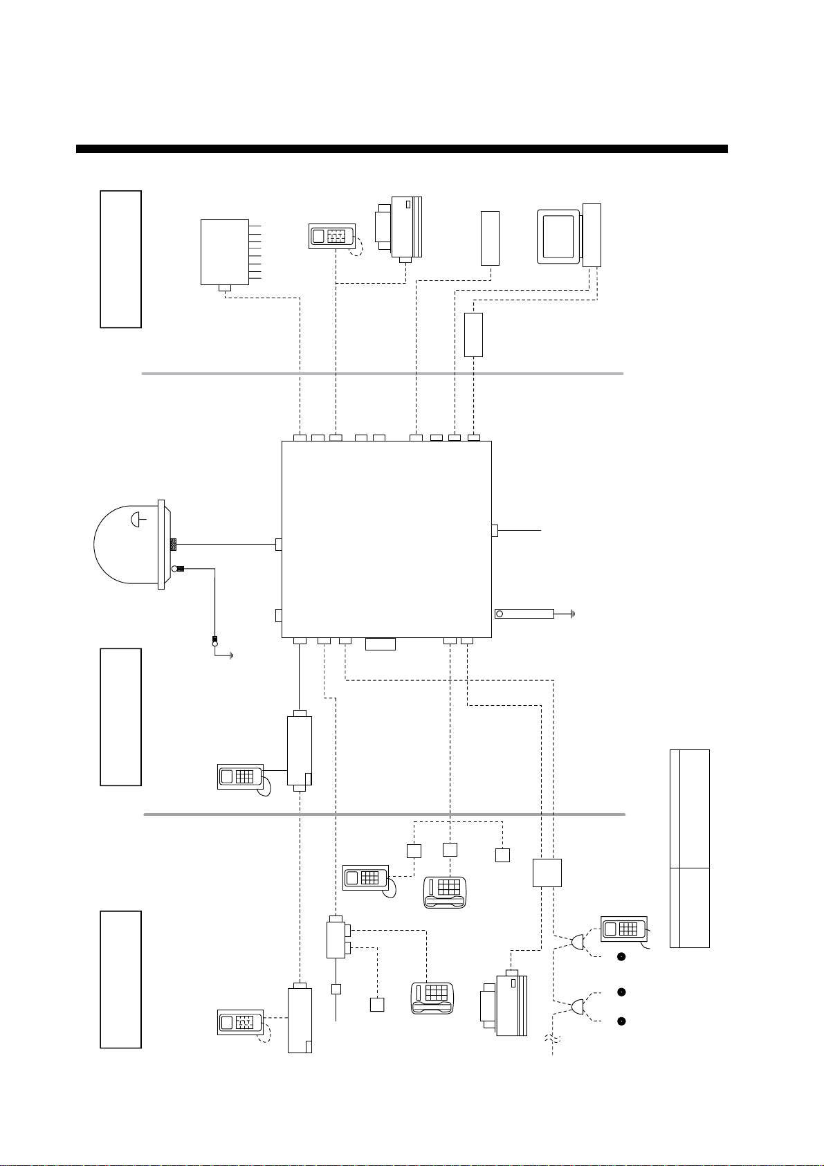
SYSTEM CONFIGURATION
G4 FAX
(user supply)
external equipment
PABX
Ship's Analogue
ISDN telephone
Gyro/GPS
(not requipment)
PC or Data
Equipment
SF-170 : Mast mounted
radome
SF-171 : Desk mounted
radome
GPS
SF-170
SF-171
ANTENNA UNIT
M12
8D-FB- CV "30M" 20S0021-0
8D-FB- CV "50M" 20S0022-0
12D-SFA-CV "100M" 16S0211-0
20- 60m : N-P8DFB
60-100m : N-P12DSFA
16S0116-0
M12
ISDN Cable
TTYCY-1 or
CO-SPEVV-SB-C 0.2x1P
(10/20/30/40m)
ISDN4
Tel 1 (2W)
Tel 2 (2W)
20- 60m : N-P8DFB
60-100m : N-P12DSFA
ISDN 1
ISDN 2
Broad Band output (BRO)
(15m Max)
103776
ISDN 3
TTYCY-1 or
CO-SPEVV-SB-C 0.2x1P
(10/20/30/40m)
USB
NMEA-0183(4W)
SF-270
Communication unit
SIM CARD
RS232-USB
converter
RS232C Cable
RS232C Cable
(M)
RS232
RS232
Tel 4 (2W)
Tel 3 (2W)
AC IN
GND
φ1, 50-60Hz
100-240V AC
*Total Number of ISDN : Max 8 (include TA)
viii
standard supply
optional supply
ISDN Handset
SF-870
ISDN Handset
SF-870
Distress Alert
Unit
Distress Alert
Unit
SF-370
SF-370
DBAR104001/888
Analogue
Telephone
QDGY911912
TA
Analogue- to ISDN TA
Adapter
Incoming
Indicator
220VAC
ISDN
Wall Socket
102176
TTYCY-1 or
CO-SPEVV-SB-C 0.2x1P
(10/20/30/40m)
MJ-2S
FC755D1
(Japanese)
ANALOGUE
WALL SOCKET
(OP16-11)
FC755D1
(Japanese)
TTYCY-1 or
CO-SPEVV-SB-C 0.2x1P
(10/20/30/40m)
Incoming
Indicator
G3 FAX
FAX-8070P/3850
CO-SPEVV-SB-C 0.2x1P
(10/20/30/40m)
Connection Box
QUFC911918
ISDN Handset
102176
ISDN
Wall Socket
SF-870
Environmemtal Category
Antenna unit To be installed in an exposed area
Commnication unit
Distress alert unit To be installed in a protected area
ISDN handset, etc
Page 11
1. INTRODUCTION
1.1 General
The FELCOM 70 consists of the Above Deck Equipment (ADE) and Below Deck
Equipment (BDE).
Above Deck Equipment - ADE
The FELCOM 70 Above Deck Equipment consists of:
Servo stabilized antenna dish with RF-Transceiver
•
Mast mounted radome, or
•
Deck mounted radome
•
Below Deck Equipment - BDE
FELCOM 70 Communication Unit (CU)
The
electronic part - is designed for wall or desktop installation.
The CU mains input is 100 - 240 VAC. The power requirement is approx. 40 W
in receive/idle mode, and approx. 150 W in transmit mode.
The CU supplies 48 VDC power to the ADE through the coaxial cable.
ISDN Handset
- which constitutes the major
ISDN Handset
The
keypad and built-in display allow dialing and control of the
CU and antenna.
Distress Alert Unit
The Distress Alert Unit provides remote activation of an alert transmission and
indication of incoming distress calls.
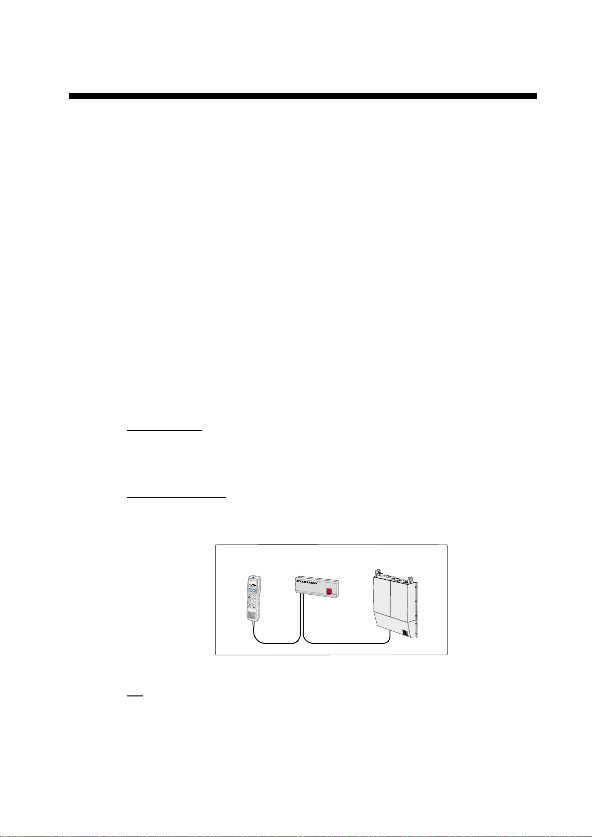
Handset
DIAL 00+INTL
T
E
L
.
N
O
.
+
#
DEL
1
2
3
4
5
6
7
8
9
0
Distress Alert Unit
Communication Unit
D
I
S
T
R
E
S
S
CU
FELCOM 70 satellite terminal
CD
The CD ROM supplied with FELCOM 70 contains program for PC (vtLite Marine
and driver software.
1-1
Page 12

1. INTRODUCTION
1.2 Communication services
FELCOM 70 pr ov ides the follow ing services :
• ISDN: - 64 kbps Mobile Data Ser vi c e ( UDI)
- 56 kbps Mobile Data Service
- 4.8 kbps s peec h
- 64 kbps speech
- 3.1 kHz audio (64 k bps) (e.g. G4 FAX)
• RS-232: - 64 kbps Mobile Data Service (UDI)
- Mobile Packet Data Service (MPDS)
• RS-422: - 64 kbps Mobile Data Service (UDI)
• USB: - 64 kbps Mobile Data Service (UDI)
- Mobile Packet Data Service (MPDS)
Note: USB Interface is currentl y not support ed.
• ANALOGUE: - 4. 8 k s peech/64 k speech
- 3.1 kHz (e.g. telefax Gr.3)
Internal communicati on
Equipment connec ted to the various interfaces may communic ate wi th each
other via an int er nal MSN (Multi ple Subscriber Num ber ) as s igned to each unit .
Control interface
The RS-232/RS-422 or USB port allows connecti on of a PC for configuration of
the FELCOM 70 Communicat ion Unit (CU).
A PC program (vtLite Marine) that provides the software to operate and
configure t he CU is suppli ed on the enclosed CD (requires at least Windows
95).
D
I
A
L
0
0
+
I
N
T
L
T
E
L
.
N
O
.
+
#
D
E
L
1
2
3
4
5
6
7
8
9
0
Additional
ISDN Handsets
Distress Alert Unit
D
Additional
i
s
t
r
e
s
s
Analogue telephones
(wall or desk)
Telefax
(Group 3 or 4)
PC
(user supply)
1-2
Additi onal equipment
Page 13

2. OPERATION FROM HANDSET
2.1 Display Panel and Key Panel of ISDN Handset
Handsfree microphone
Display indicators:
appears at hook OFF
flashes when receiving a call
Net provider & Ocean Region
appears when loudspeaker
is ON
appears when selecting
ALPHA
letters on the keypad, e.g. for
Phone Book entries
signal strength indicator
alarm indicator
Function keys:
allows adjusting the earpiece
volume during conversation
opens/closes Phone Book
reverts to previous position
used to transfer a call
selects function menu
handsfree microphone/
loudspeaker ON/OFF (hook
ON/OFF when in cradle)
hook ON/OFF
. . . . . number keys.
The keys include letters for
Phone Book entries.
enters selected choise
deletes last character or
complete entery
scrolls up/down through
function menu/choices
Handsfree loudspeaker
Display and keys
ISDN
ALPHA
KDD IOR
Ready for call
Hook ON magnet
click!
Holder/cradle wallmounted
2-1
Page 14

2. OPERATION FROM HANDSET
2.2 Switching ON
The ON/OFF switch l oc at ed on the upper end of the Communication Unit
swit c hes all basic units of the FELCOM 70 terminal on/off:
• the I S DN Handset
• the Communication Unit (CU), and
• the Antenna Unit.
See figure below for locat ion of the power ON/OFF switch and indi c ator.
SIM card
Cover
Power
*
indicator
Power
ON/OFF
switch
2-2
Location of SIM card and ON/OFF switch
*: Insert SIM card, contact upside down.
Note: Wait about 10 seconds to turn on the power after turning it off.
Page 15

2.3 SIM card
The SIM c ar d car r ies subscri ption infor m ation from your Net service provider on
an integrated c ircuit. The FELCOM 70 used with t he S IM card assumes t he
identity of the SIM card.
The SIM c ar d has its own set of Inmarsat Mobi le Num bers (IMN) on which the
user can be cont ac t ed irrespec t ive of the FELCOM 70 used. A ll outgoing calls
will be bi lled to the owner of the SIM card.
The SIM c ar d is protected by a SIM PIN (Pers onal Identification Number) .
Contact y our Net service provider if you do not have the PIN code.
If the PI N c ode entered does not match the PIN code on the SI M card, operat ion
with that particular SIM card will lock-up after three failed attempts. You must
then use the SIM un-bl oc k c ode ( P UK c ode) provided by your Net servi c e
provider to un-lock the card. Contact your Net servic e provider if you do not
have the PUK co de.
Note: When the PUK is us ed, the SIM PIN is set to 1 2 3 4.
To change or disable the PIN code, see "5.3 Access le vel" later in this manual.
The SIM c ar d can s tore various inf or m ation, e.g.:
2. OPERATION FROM HANDSET
• PIN c ode (P er s onal Ident ificati on Num ber )
• Phone book
• Allowed and preferred N et service providers
Note: FELCOM 70 can be us ed wit h or without SIM card. The Net s er vic e
provider, however, sometimes requires the use of SI M c ar d.
The SIM c ar d dr iver is located on the upper end of the Communication Unit , see
page 2-3. T he cover must be removed to access the card slot. The cover is
attached by two serrated s c r ews. No tool s ar e required to loos en the screws.
Note: I ns er t the SIM card at idle state ( page 2- 4).
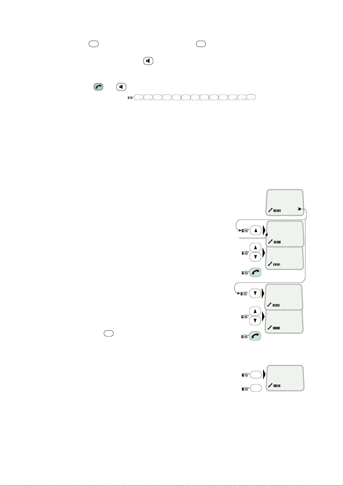
2.4 ISDN Handset
When connect ed, the hands et is automat ically set to Fleet mode, pr ovi ding an
idle di s play as shown on next page.
To switch back to I S DN Hands et mode, press and hold down
ON power.
Swit c hing bac k t o Fleet mode is then achieved as follows:
1. Open the MENU and scr oll down
to Set to Fleet
OK
2. Press
The handset will now
stay in Fleet mode.
.
MENU
>Active MSN
Kayclick
Ringer
Answer beep
Backlight
Language
MSN
Protocol
OK
Set to Fleet
DEL
when turning
2-3
Page 16

2. OPERATION FROM HANDSET
2.5 FELCOM 70 starts up
FELCOM 70 automatically initi alizes the s ystem and searc hes for the satellite.
Furuno Fleet
Euro-ISDN
Enumerating
KDD
Initializing
IOR
KDD
Searching
IOR
KDD
Ready for call
IOR
See “3.2 Satellite search” in t his manual t o r estart a sear c h manually.
If required, see "3.4 Selecting d ef ault Net service provider".
Idle
When idle, the IS DN Hands et displays as follows.
Ocean Region
Service provider
Signal strength
indicator
Alarm indicator
KDD IOR
Ready for call
The alar m indicator flashes when an alarm condition occurs . T he indicator s tops
MENU
once the alarm has been read in the Display Handset by pressi ng
>
Inform ation > Alarms & messages” .
The indicator continues to be displayed i f the alarm condition persists.
Note: If the searching begins suddenly due to satellite blocking, restart a search
manually, specifying y our oc ean r egion. See page 3-3 for detai ls.
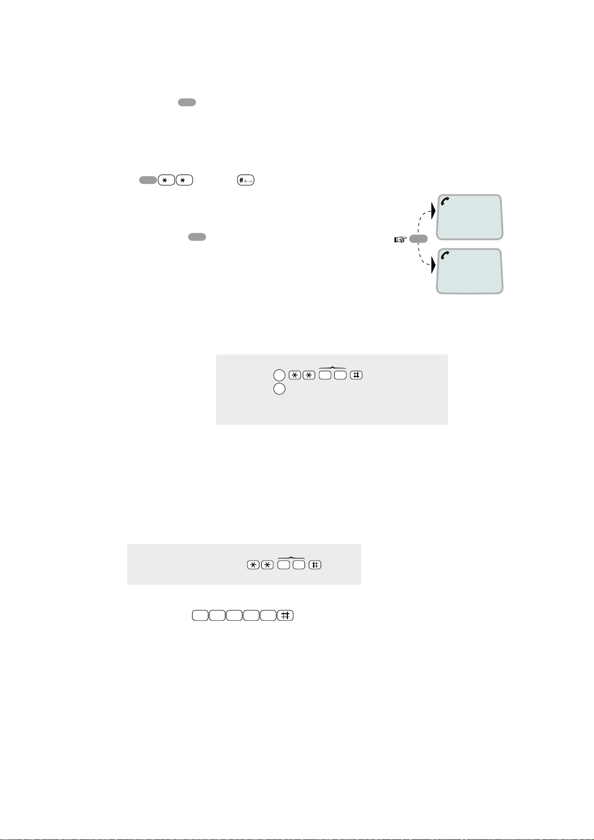
2.6 Making a call
1. Dial 00, country c ode and s ubs c r iber number, e.g. :
0 8
0
abc
1
6
7
pqrs
mno
Japan
For normal call
For handsfree call
• When entered, the display
reads:
• When the remote end answers ,
the displ ay reads:
The timer star ts.
2. End the cal l by pressing
hook ON/OF F
replacing the handset in the c r adle.
2
4
abc
pqrs
abc
Timer, minutes:seconds
, or
4
abc
0 0
7
pqrs
Dial (4.8K)
008167244700
Calling ...
008167244700
Connected 09:46
008167244700-
Disconnected
2-4
Page 17
Use
DEL
key to modify entries: Pressing
Holding the key more than 0.5 second erases the whole number.
Use the handsfree key
Alternative dialing:
Press
or t o get the dialing tone, then dial the number.
2.7 Redialing
The Redial Memory stores the last 30 called and received numbers (since
incoming IMN numbers are not conveyed fr om “ashore”, the received numbers
are listed by local MSN numbers.)
The data are erased when disconnecting the handset or FELCOM 70 is switched
off.
To redial calls made:
1
Press the arrow up key to recall the latest
number dialed.
2
Use the arrow keys to scroll through
the list.
3
Pressing hook ON/OFF sends the chosen
number.
To view calls received:
4
Press the arrow down key to recall the
last number received. Scroll
through list.
To delete a listed number:
5
Press
from list.
Press OK to delete:
Revert to idle:
DEL
to clear the chosen number
0 8
0
2. OPERATION FROM HANDSET
DEL
key once, erases one digit.
to toggle the loudspeaker ON/OFF.
#
abc
1
6
pqrs
2
7
mno
pqrs
4
4
abc
abc
"Redial list entry"
appears if no number
is stored
0 0
abc
7
pqrs
A a
DEL
OK
KDD IOR
Ready for call
OUT: Aug 01 02:11
008179803113 01
OUT: Aug 01 01:45
008179560215 02
IN:JAN20 13:09
20 01
INFEB10 16:11
20 02
Clear?
00467244700
››
››
2-5
Page 18
2. OPERATION FROM HANDSET
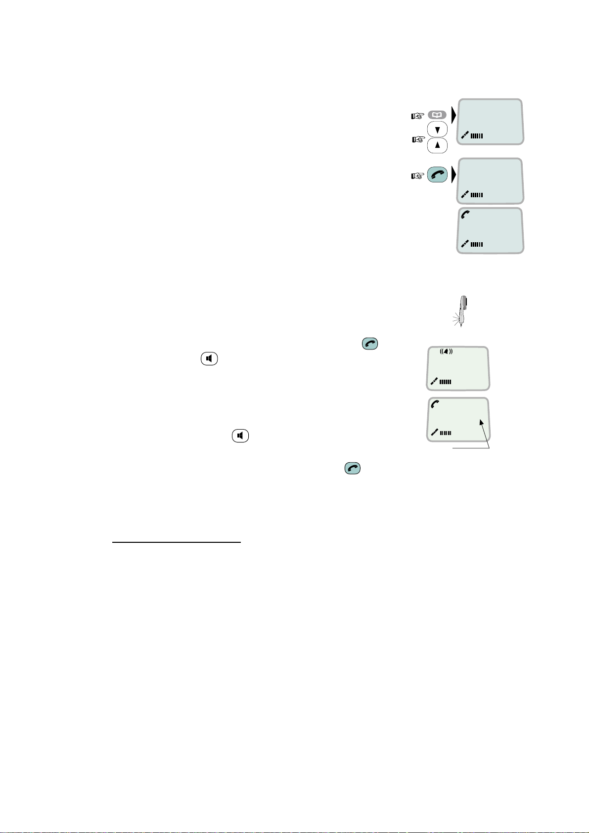
2.8 Dialing from phone book
1
Press the phone book key and scroll through
the phone book.
2
Press the hook ON/OFF key to call the
selected number.
2.9 Incoming calls
The handset rings when receiving a call. The ringing symbol
flashes until the call is answered.
ALPHA
›› BT
Furuno
ALPHA
BT
Calling ...
Answer the call by pressing hook ON/OFF key or
•
handsfree key
4.8 Speech
With the ISDN Handset in the cradle, the loudspeaker and
microphone are ON for handsfree operation.
00:00
If lifting the handset , the loudspeaker turns off.
Use the handsfree key
End the call by pressing hook ON/OFF key , or replacing the handset in
•
to toggle the loudspeaker on/off.
Timer,
minutes:seconds
the cradle.
Reject the call by pressing
•
DEL key
Internal communication
When receiving a call, the caller`s MSN number will appear in the display (if
programmed).
2-6
Page 19
2.10 Call hold an d transfer
2. OPERATION FROM HANDSET
Pressing
R
during a conversation will put the current call on hold. Another call
may now be made.
Switching between the two calls:
The 2nd call is established by keying:
•
R
The original call is put on hold, and 2nd connected.
•
Toggling between the two calls is achieved by
•
pressing
[MSN]
R
repeatedly.
Call transfer (connection via satellite):
MSN/Handset ld
R
toggles between subscribers
R
Exception!
Transfer from analogue to ISDN is not possoble.
2 0
1 on hold
**20#
R
2 on hold
Hang up
2.11 Internal communication
FELCOM 70 allows calls to be made internally between the connected ISDN and
analogue telephones.
Internal calls:
MSN
ISDN-to-ISDN
telephone:
Note:
If the telephone lack the *-key, 103 may be dialed instead,
f.ex.:
1 0 3 2 0
When receiving a call, the caller’s MSN number will appear in the display (if
programmed). When FELCOM 70 is busy with a satellite link call, it is possible to
make internal calls.
(example)
2 0
2-7
Page 20

2. OPERATION FROM HANDSET
2.12 Various call procedures
Short number dialing from Phone Book (prefix 23)
2 3 1 5
fetches and sends the telephone number stored in the Phone
Book under short number 15.
Short number dialing (prefix 23) through selected Net service provider
3
2 3 1 5
fetches and sends the telephone number stored under
short number 15 via the selected Net service provider (KDDI=no.3).
Service calls
Special information services are accessible with 2-digit service address code.
Note:
Not all Net service providers off er every service.
Examples:
Obtaining assistance from the International Operator:
1 1
Calling the technical staff of the Land Earth Station (LES):
3 3
Telefax
On a telefax with keypad, enter
as the last digit before starting
transmission.
Note:
Some types of equipment do not have # implemented in software even if
the #-key is on the keypad. Then in front of the telephone number use.
903 if dialing the number digit by digit, or
902 if for the number to be sent as a block. E.g.:
9 0 2 0 0 4 7 6 7 2 4 4 7 0 0
2-8
Page 21

2.13 To call FELCOM 70
2. OPERATION FROM HANDSET
Dial the international prefix (normally 00) followed by
e.g. 00
870
762420510.
The common Ocean Region access no. 870 connects the call to the dialed
FELCOM 70 terminal regardless of the Ocean Region the user currently
communicates through.
If the Net service provider does not support access no. 870, call t he Ocean
Region directly:
871 – AOR-E
872 – POR
873 – IOR
874 – AOR-W
(Atlantic Ocean Region East)
(Pacific Ocean Region)
(Indian Ocean Region)
(Atlantic Ocean Region West)
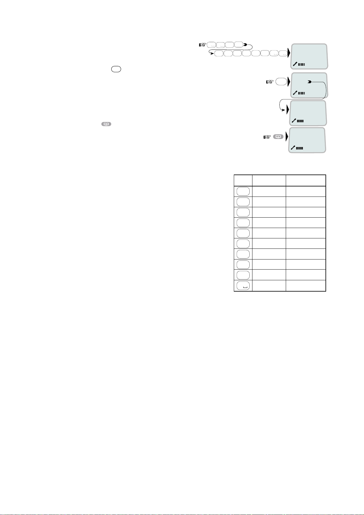
2.14 Phone book entry
The entries in the FELCOM 70 phone book may consist of maximum 15
characters and 15 digits. Typical 6-character/8-digit entries yield a total of 85
phone numbers. The number/name list is stored in the Communication Unit.
Programming:
1
Open the
2
Open the
before starting to key in characters:
phone book > menu
Add entry
function by pressing Ok
870
and the IMN number,
››
.
OK
Add entry
Edit number
ALPHA
Add name:
3
Enter the name, e.g. Fera ASA:
Press [3] key three time to enter “F” and as follows:
Note that the additional characters accessible
with the key appear momentarily.
See the character table on next page.
For modifying an entry,
see “2.15 Phone book editing.”
An entry can be erased by pressing
DEL
4
Press the OK key.
#
A
a
#
7
2
0
2
7
2
OK
pqrs
abc
abc
pqrs
abc
Fe_
Add name:
Fer_
Add name:
Fera_
Add name:
Fera _
Add name:
Fera_A
Add name:
Fera_AS
Add name:
Fera_ASA
Add name:
3
def
A
a
ALPHA
ALPHA
ALPHA
ALPHA
ALPHA
2-9
Page 22
2. OPERATION FROM HANDSET
5 Enter the tel ephone number e.g.:
OK
6 Pressing
st or es the entry in the
phone book.
7 Press
to revert to idle.
The character table shows all the charac ters acces s ible.
Notes:
• The # -key toggles betw een upper-cas e
and low er - c ase c har ac ters.
• To enter none Anglo-A m er ican characters,
change language to Norwegian.
• Names w r itten with none A nglo-Americ an
characters such as Æ, Ø, Å etc., can onl y
contain 6 di fferent s pec ial charact er s
(however, 2 equal charact ers c ount as 1).
1
8
0
tuv
0
4
abc4abc
2
6
mno
abc
7
pqrs
0
7
pqrs
0
Number...
008167244700
OK
Saving
20
››
Nera ASA
Neratek
KDD IOR
Ready for call
ALPHA
Key Uppercase Lowercase
. , ? ! - : ; / 1 . , ? ! - : ; / 1
1
ABCÆÅÄ2 abcæåä2
2
abc
DEF3 def3
3
def
GHI4
4
abc
JKL5 jkl5
5
jkl
MNOØÖ6 mnoøö6
6
mno
PQRS7 pqrs7
7
pqrs
8
tuv
TUVÜ8tuvü8
9
wxyz
WXYZ9 wxyz9
0
_0 _0
ghi4
2-10
Page 23
2. OPERATION FROM HANDSET
2.15 Phone book editing
Open phone book menu and scroll down to the
required function.
If "Sort by ShrtNo" is selected, the function
switches to "Sort by Name".
ALPHA
to be entered.
Use
appears when letters are
DEL
to modify entries.
Add Entry
Edit
number
Edit name
Delete
Search
book
See
number
Copy
Short by
ShrtNo
Sort by
name
››
OK
Add name:
Furuno Satcom_
OK
Number:
004767244700
OK
Edit name:
Furuno Satcom
OK
OK
Name search:
_
OK
[1] 0047672447
00
OK
Short Number:
2_
OK
[1] 0047672447
00
OK
Furuno
Add Entry
Edit number
Edit name
Delete
Search book
See number
Copy
Sort by ShrtNo
ALPHA
ALPHA
Deleting
ALPHA
ALPHA
ALPHA
ALPHA
ALPHA
2-11
Page 24

2. OPERATION FROM HANDSET
2.16 Analogue telephone
muting
1 Speaker
2 Keypads
3 R-button (not used)
4 Storing / Microphone
5 Last number redial
6 Hook on / off
7 Line cable outlet
8 Microphone
9 Memory ( s tored numbers)
10 Volume control
11 Ringing signal High / Low
Outgoing call
1 Lift hands et and receive dial tone
2 Dial the subsc r iber number (and #)
3 When finished, repl ac e t he hands et
Redialing
If t he s ubs c riber is busy, or you want to mak e a new call to the l ast dialled
subscriber, you can lift the handset, receive new dial tone and then pr es s the
[REPETER] button.
Note that this button i s for manually dialled numbers only. S tored numbers w ill
not be repeated usi ng this method.
Storing abbreviated numbers
Ten subscriber numbers can be stored in the telephone’s memory in short from.
The numbers c an be used for outgoing call, by pushing 2 buttons only.
1 Lift handset and press [LAGRE/SEKR] button (Don’t worry the dial tone)
2 Press [MINNE] button.
3 Select rel evant s toring address by pushing one butt on.(0 - 9)
4 Dial the subsc r iber no. and # (max. 21 digit s ) .
5 Press [LAGRE/SEKR] button.
6 Replace handset. The number is stored.
7 Repeat the step 1 - 6 to s tore additi onal numbers.
If required to change a number, just overwrite existing number.
2-12
Page 25

2. OPERATION FROM HANDSET
Abbreviated call
1 Lift hands et and receive dial tone
2 Press [MINNE] button.
3 Press relevant st oring address (0 – 9). The subs c riber number is
automatic ally dialled.
Note: If y ou put the analogue phone, f ac ing the key pad down f or holding on
call, the line will cut.
2-13
Page 26

2. OPERATION FROM HANDSET
This page is intentionally left blank.
2-14
Page 27

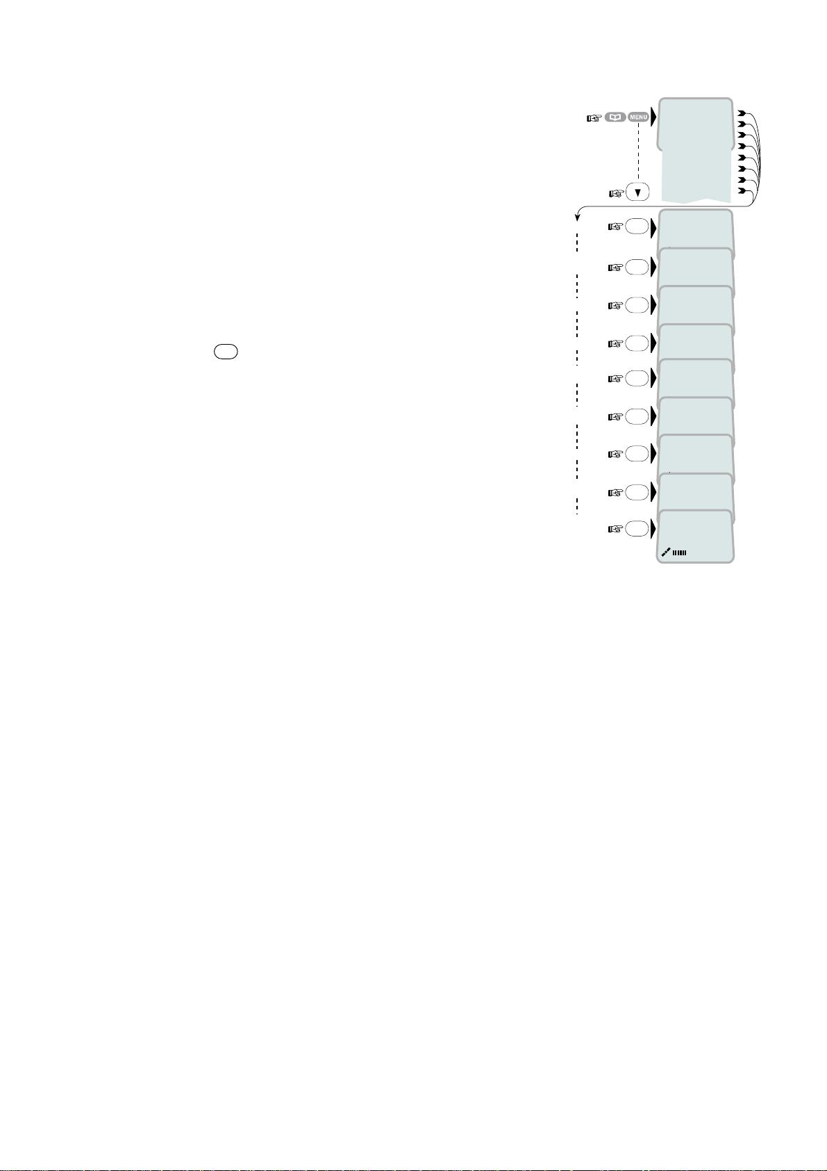
3. HANDSET FUNCTIONS
3.1 Overview
MENU
ESC
››Sat. Search
Phone setup
Set Network
Priority Call
Ports
Information
Opening Search
››Active MSN
Keyclick
Ringer
Answer beep
Backlight
Protocol
SW version
V1.4.00 290703
Chksum:00F32852
›› Euro-ISDN
Nl-1
›› 001/CMC
002/Stratos
003/KDD
005/OTE
››Find Any
AOR-W
AOR-E
POR
IOR
Region 4
Region 5
Region 6
Not in use
Region 7
Searching...IOR
Elevation 0
Elevation: 0...90
›› #1: 4.8 Speech
#2: 64K Speech
›› On
Off
›› Tone
Volume
›› On
Off
›› On
Off
30 second
Dimmer
o
Tuning to IOR
Elevation 17
KDD IOR
Logging On
›› Tone#1
Tone#2
›› Low
Medium
High
Increasing
›› Dimmer [100%]
90%
10%
KDD IOR
Ready for call
See next pagereverts to idle
3-1
Page 28

3. HANDSET FUNCTIONS
MENU
ESC
››Sat. Search
Phone setup
Set Network
Priority Call
Ports
Information
reverts to idle
››Safety Call
Urgency Call
Distress T est
Test Buzzer
››Diagnostics
Forward ld
Version Info
Network Info
Alarms & Msgs
Position
Speed/Course
›› Port A
Port B
On
›› Off
›› HW(fwd):A98853
IOR Spot: 6
Ready for call
›› Clear Causes
Alarms List
Info Log
›› 010d29m02s E
059d52m11s N
Speed : 10.5
Course: 098
››Driver switch
Speed
Format
Flow control
››System
Ctrl SW
DSP
Monitor
KDB
RFB
ATB
Only appears with
Diagnostics On
›› Speed
Format
Flow control
›› RS-232
RS-422
REL 2.0
06 Sep 2003
101476 Ver.2.0
05 June 2003
2.2
1.05
1.20
1.00
Furuno Marine 3
10
1200bps
2400bps
4800bps
9600bps
19200bps
38400bps
57600bps
›› 115200bps
d=7,p=none,s=1
d=7,p=e,s=1
d=7,p=0,s=1
d=7,p=m,s=1
d=7,p=s,s=2
›› d=8,p=none,s=1
d=8,p=e,s=1
d=8,p=0,s=1
d=8,p=m,s=1
d=8,p=s,s=1
d=8,p=none,s=2
d=8,p=e,s=2
d=8,p=0,s=2
d=8,p=m,s=2
none
›› rts/cts
xon/xoff trans
xon/xoff
3-2
Page 29
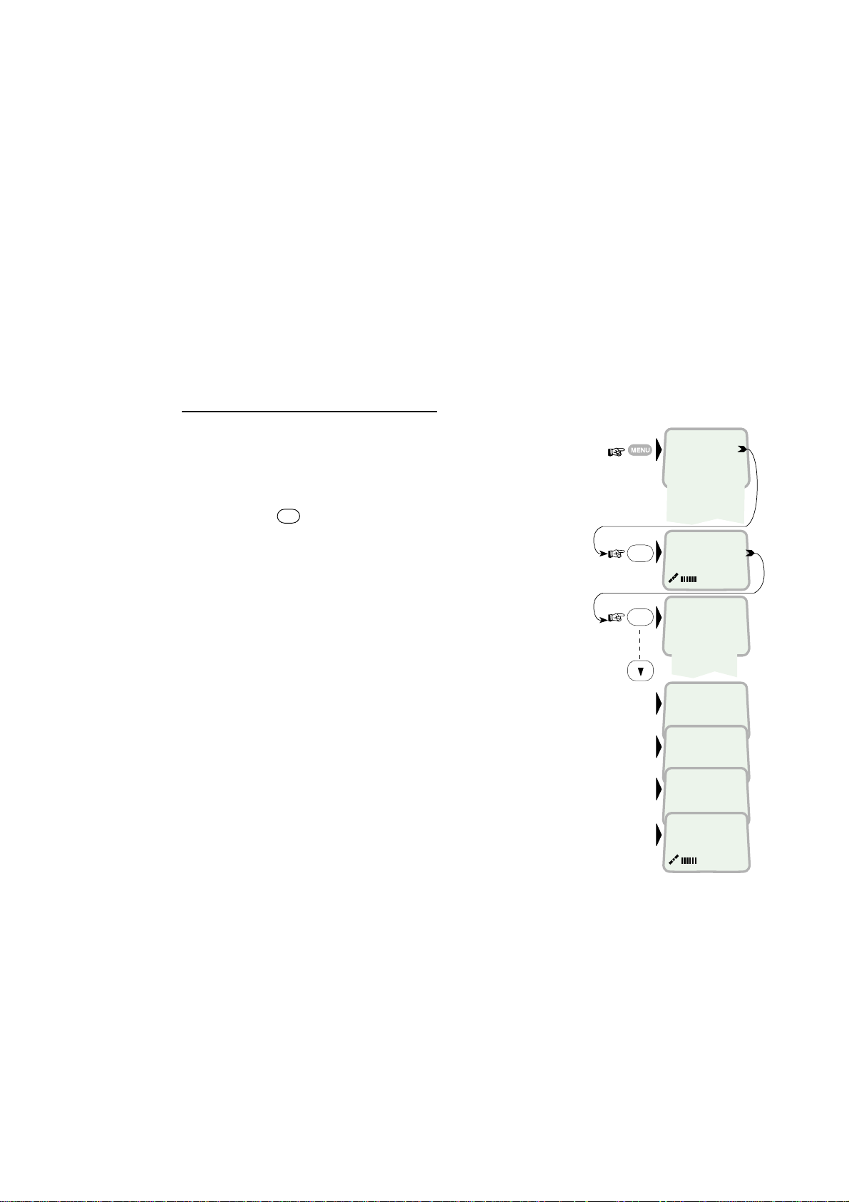
3.2 Satellite search
Some geographic locations allow contact with more than one Ocean Region
satellite. It is recom mended to choose an Ocean Region providing good signal
quality and cost-effective communication.
Use the
your location:
To select another Ocean Region:
Satellite Coverage Map
Atlantic Ocean Region West:
Atlantic Ocean Region East:
Pacific Ocean Region:
Indian Ocean Region:
3. HANDSET FUNCTIONS
on next page to select the Ocean Region at
AOR-W
AOR-E
POR
IOR
1
Open the
MENU
and press
Sat. Search
.
Pressing
OK
opens the list of searching
alternatives.
2
Select as required.
When selecting Find Any, the antenna searches
one Ocean Region after the other until a satellite
signal is found.
The antenna performs an hemispheric search at
antenna elevation angles varying within 0°
through 90°.
OK
OK
››Sat. Search
Phone setup
D
Set Network
Priority Call
+
Ports
''
Information
Opening Search
››Find Any
AOR-W
AOR-E
POR
IOR
Searching...IOR
Elevation 0
Tuning to IOR
Elevation 17
Telenor IOR
Logging on
Telenor IOR
Ready for call
3-3
Page 30

3. HANDSET FUNCTIONS
180 W
60 N
30 N
LATITUDE
0
30 S
60 S
160 W
POR
178 E
140 W
120 W
AOR-W
54 W
20 W 0 20 E80 W 60 W 40 W100 W
5o Elevation5o Elevation5o Elevation
LONGITUDE
AOR-E
15.5 E
40 E 60 E
IOR
64.5 E
80 E
100 E 120 E 140 E 160 E
POR
178 E
5o Elevation5o Elevation
180 E
60 N
30 N
LATITUDE
0
30 S
60 S
TEL: 870 or 872
Pacific Ocean Region
POR
TEL: 870 or 874
Atalantic Ocean West Region
AOR-W
TEL: 870 or 871
Atlantic Ocean East Region
Indian Ocean Region
AOR-E
Satellite Coverage Map
TEL: 870 or 873
IOR
TEL: 870 or 872
Pacific Ocean Region
POR
3-4
Page 31

3.3 Phone setup
3.3.1 Active MSN (Multiple Subscriber Number)
When making a call , the device connected to FELCOM 70 identifies itself by its
MSN number.
Although specific MSN numbers may be programmed in ISDN handset for bot h
the 4.8K Speech and 64K Speech services, only one can be active at one time
for outgoing calls.
The first ISDN Handset connected has the following MSN numbers:
Identity MSN number Name/speech quality
#1: 20 4.8 Speech
#2: 30 64K Speech
To change active MSN:
3. HANDSET FUNCTIONS
1
Open the
MENU
and select the
2
Select required identity/speech quality.
Note:
To change MSN number, see “5.13 MSN
configuration” in this manual.
Note:
To close the menu press the ESC key
several times.
3.3.2 Keyclick
When activated, a click is heard when pressing a key. The keyclick can be
turned on/off as follows.
1
Open the
2
Select the
3
Press
4
Press
MENU
Keyclick
OK
and scroll to On or Off, as required.
OK
to store the setting.
and scroll down to
Active MSN
function.
and scroll down to
function.
Phone setup
Phone setup
,
.
OK
OK
OK
OK
Sat. Search
››Phone setup
D
Set Network
Priority Call
+
Ports
''
Information
››Active MSN
Keyclick
›› #1: 4.8 Speech
#2: 64k Speech
Sat. Search
››Phone setup
Set Network
Priority Call
Ports
Information
››Active MSN
Keyclick
›› On
Off
3-5
Page 32

3. HANDSET FUNCTIONS
3.3.3 Ringer
The tone sound and level heard when the phone
rings may be selected as follows.
1
Open the
MENU
and select
2
Press
OK
to select the
3
Press
tone.
4
Press
OK
again and scroll down to required
OK
to store the selected one.
5
Select the
to the
6
Pressing
Ringer
Volume
OK
function.
lists the choices. Scroll down to
required sound level, and press
3.3.4 Answer beep
Phone setup > Ringer
Tone
function.
function again and scroll down
OK
to store it.
Sat. Search
››Phone setup
Set Network
Priority Call
Ports
Information
.
OK
OK
OK
OK
OK
Keyclick
››Ringer
››Tone
Volume
›› T one#1
Tone#2
Tone#3
Tone#4
Tone#5
Tone#6
Tone#7
Tone#8
Tone#9
Tone
››Volume
›› Low
Medium
High
Increasing
FELCOM 70 may be set to emit a signal in the handset when an outgoing call is
answered. The signal will also sound when a call is transferred at the remote
end.
The signal is not active during handsfree calls.
The answer beep can be turned on/off as follows.
1
Open the
and select the
MENU
Active MSN
and scroll down to
function.
Phone setup
,
Sat. Search
››Phone setup
Set Network
Priority Call
Ports
Information
2
Scroll down to the
3
Press
4
Pressing
OK
and scroll to On or Off, as required.
OK
Answer beep
function.
stores the chosen mode.
OK
››Active MSN
Keyclick
Ringer
››Ånswer beep
OK
›› On
Off
3-6
Page 33

3.3.5 Backlight On/Off
The display and keypad backlight can be set to:
On
•
, permanently ON
Off
•
, permanently OFF
30 second
•
s ON when pressing a key or receiving a call, and stays ON 30
secs after last event.
Dimmer
•
, intensity adjustable in 10 steps.
Changing the setting:
1
Open the
MENU
and scroll down to
and scroll down to the
2
Press
OK
and scroll down to required setting.
3
Pressing
OK
at
Dimmer
adjustment window.
Adjust with up/down arrows.
4
Press
OK
to store.
3.3.6 Protocol
Phone setup
Backlight
function.
opens the backlight
3. HANDSET FUNCTIONS
Sat. Search
OK
OK
OK
››Phone setup
Set Network
Priority Call
Ports
Information
››Active MSN
Keyclick
Answer beep
››Backlight
›› On
Off
30 second
Dimmer
Dimmer [100%]
90%
10%
,
FELCOM 70 allows selection between the following ISDN protocols.
Euro ISDN
•
for connection to equipment conforming to the European ISDN
standard (default)
NI-1
•
protocol: Not used
Note:
All ISDN device and the CU must use the same protocal.
The check for current protocol:
1
Open the
and select the
MENU
Protocol
and scroll down to
function.
Phone setup
,
2
Press
3
Pressing
OK
and scroll required protocol.
OK
stores the chosen ISDN protocol.
OK
OK
Sat. Search
››Phone setup
Set Network
Priority Call
Ports
Information
››Active MSN
Keyclick
Language
››Protocol
››Euro-ISDN
Nl-1
3-7
Page 34

3. HANDSET FUNCTIONS
3.3.7 Software version
This function displays the ISDN Handset software version.
1
Open the
and select the SW
MENU
and scroll down to
version
function.
Phone setup
,
2
Press
OK
to read.
3.4 Selecting default Net service provider
The default Net service provider for a satellite (Ocean Region) is automatically
used if the user does not select another one.
When using SIM card, selection of a Net provider is restricted t o one of the
allowed Net service providers! When the Restricted Net function is enabled, and
with some SIM cards, selection of default Net service provider is not possible.
Changing default Net service provider:
OK
OK
Sat. Search
››Phone setup
Set Network
Call
Serial Ports
Information
››Active MSN
Keyclick
Protocol
››SW version
V2.0.4.0:300102
Chksum:00CB7054
1
Open the
MENU
and Scroll down to
Set Network
2
Scroll down to the required Net service provider.
3
Store the new Net service provider for the
current Ocean Region.
.
OK
››Sat. Search
D
Phone setup
Set Network
Priority Call
+
Ports
''
Information
››001/CMC
002/Stratos
004/Telenor
005/OTE
Saving data ....
3-8
Page 35

3.5 Priority calls
The Priority Call functions only appear in the ISDN Handset connect ed to the
Distress Alert Unit.
The following call priority levels are recognized by the Inmarsat system.
For Safety Call or Urgency Call, specific telephone numbers are prompted for
that must be provided by the Net service provider.
See menu to select function on page 3-2.
ISDN
ALPHA
MAY01 09:15
4.8 Speech
3. HANDSET FUNCTIONS
Safety Call
Urgency Call
Distress Test
Test Buzzer
ISDN Handset
Distress Alert Unit
DISTRESS BUTTON
Accessible when lifting the flap.
Must be pressed and held down for at
least 6 seconds to activate an alarm.
(Allows checking the alert function
when set in distress test mode)
3-9
Page 36

3. HANDSE T FUNCTIONS
3.6 Distress Alarm
The Dis tress Alert Unit allows act ivation of an alert transmission. Messages
concerni ng the alarm trans m ission and receptio n ar e display ed on the connected
ISDN Handset .
Testing t he Distress Alert Unit
Call servi ce no. 33 to arrange an alarm tes t transmis s ion with the Land E ar th
Station ( LE S ).
Procedure:
1 Open the MENU and s c roll down to Priority Call.
2 Scroll down to Distress Test.
Pressing OK enabl es the Distress Test function,
allowi ng a test alarm transmission. If requir ed, press
ESC to exit.
Press the DISTRESS BUTTON within 30 secs
more than six seconds.
If you press it after 30 s ec s , a real distres s will be
transmitted.
3 Press the # key to start test.
4 Press the
To test the buzzer, press Priority Call again (step 1)
and scroll down to Test Buzzer.
When pressing OK, the Distress Alarm buzzer
sounds for a s hort period.
key to terminate.
Sat. Search
››Phone setup
Set Network
Priority Call
Ports
Information
OK
››Safety Call
Urgency Call
Distress T est
Test Buzzer
Distress T est
Mode Enabled
OK
Self T est
BUZZER_ON
3-10
Page 37

3.7 Setting serial ports
3. HANDSET FUNCTIONS
The data speed, form at and flow control for the
as follows:
1
Open the
MENU
and scroll down to
Serial Ports
See “3.1 Overview” for available choices.
2
Select the parameter to be set for Port A.
3
Select the listed data
Speed
115200bps (default).
4
Select listed
format:
8 data bits, no parity and 1 stop bit (default)
5
Set flow control to
none
(default).
RS-232 B / RS-422 driver switch
RS-232 A
.
and B ports are set up
Sat. Search
››Phone setup
Set Network
Priority Call
Ports
Information
››Port A
››Port A
OK
Port B
Port B
OK
››Speed
Format
Flow control
››115200bps
OK
››d=8,p=none,s=1
OK
d=8,p=e,s=1
none
OK
››rts/cts
Select data speed, format and flow control as described above.
Switching the driver from RS-232B to RS-422:
6
Select
to
Serial Ports,
Port B.
and scroll down
7
Open the
scroll down to
Driver switch
RS-422.
function and
OK
OK
The RS-422 is now activated for connection
of e.g. PC using cables of up to 100 m.
The RS-232 B port is disconnected.
OK
››Sat. Search
Phone setup
Set Network
Priority Call
Ports
Information
Port A
››Port B
››Driver switch
Speed
Format
Flow control
RS-232
››RS-422
3-11
Page 38

3. HANDSET FUNCTIONS
3.8 Information available
Open the menu and scroll down to read various information, as indicated
(examples):
››Sat. Search
Phone setup
Set Network
Priority Call
Ports
Information
››Diagnostics
OK
Forward ld
Version Info
Network Info
Alarms & Msgs
Position
Speed/Course
On
OK
Off
HW(fwd):A98853
IOR Spot: 5
Ready for call
››Clear Causes
Alarm List
Info Log
010d29m02s E
059d52m11s N
Only appears with
Diagnostics ON
OK
OK
››System
Ctrl SW
DSP
Monitor
KDB
RFB
ATB
FELCOM 70
30 Aug 2002
101476 Ver . 1.2
27 July 2002
1.1
1.05
1.20
0.140
Speed: 10.5
Course: 098
Type: 160.110
3-12
Page 39

4. OPERATION FROM PC
4.1 Installing the PC program
The vtLite Marine program allows FELCOM 70 to be operated or configured
from a PC, i nc luding functions such as:
• Phone book
• Traffic log
• Configurat ion of ports
(ISDN/analogue/RS-232/USB/RS422)
For an explanat ion of the functions, see later in this manual.
The vtLite Marine progr am is available on the encl os ed CD and must be
instal led on the PC hard dis k .
Note: To install the vtLite Marine, the user name of the PC should be one- byte
characters.
SILENCE
SW
IND
NMEA
TX
TX
RX
RS-422
Max 100 metres
NMEA
RX
TEL 1
TEL 2
TEL 3
TEL 4
ISDN
TX
TX
ISDN
ISDN
TX
TX
TX
TX
RX
RX
RX
RX
RX
RX
ISDN
TX
ISDN
ISDN
TX
RX
RX
ISDN
ISDN
TEL 4
TEL 3
USB
RS-232
B
USB port
PC serial port
PC serial port
RS-232
A
DTE
4-1
Page 40

4. OPERATION FROM PC
Procedure:
1 Insert t he CD and open it f rom the “My Compute r ” icon.
2 Install the “vtLite Marine” to the PC hard dr ive.
a. Open the “vtLite 6.0” folder.
b. Double-click the “setup.exe” icon and follow the instruction displayed.
c. Double-click the “furuno.bat” icon.
3 Connect the serial cable between t he P C s er ial port and the RS-232 port on
the FELCOM 70 Communicat ion Unit. S ee pr ev ious page.
4 Start the vtLi te Marine pr ogr am by clicking Start>Programs>vtLi t e M arine.
5 Switch ON t he Com m unication Unit.
If no contact, click Mode>Terminal MMI.
6 If no contac t, press YES butto n to try auto detect.
7 Click Configure>Port to check the port settings.
4-2
Page 41

4.2 Starting up
Switch ON FELCOM 70. See figure on page 2-3 for location of the ON/OFF
•
switch.
4. OPERATION FROM PC
Turn ON the PC and click
•
Start>Programs>vtLite Marine
.
1
The satellite search program is initialized.
See also "3.2 Satellite search".
1
2
FELCOM 70 starts searching for
last known satellite
(Ocean Region) as
default.
3
When receiving a satellite signal, a signal strength bar will appear in the
search window. The longer the signal bar or higher the signal strength
indicator value, the better the signal quality. The maximum marker indicates
the highest signal strength achieved during the current search.
3
580
S/N ratio
4-3
Page 42

4. OPERATION FROM PC
Note: It is r ec om m ended that the signal strength reading (S/N=Signal/Noise
ratio) should be at least 550, typi c ally 660. T he antenna will automatically
fine-tune to the best si gnal and accept it.
Clicking Seek starts the search again. If required, select a specific satellite by
clicking New.
See also "5.4 Selecting default Net service provider".
4 The equipment is ready f or us e when the Main window appears.
4
To m ake a c onnec tion, see "2.6 M aking a call"
4-4
Page 43

4.3 Phone book
Adding and editing entries can also be done from the handset, see “Chapter 2
OPERATION FROM HANDSET”.
Phone book capacity
4. OPERATION FROM PC
CU SIM card
(Data vary with card type)
Phone numbers: 100 entries 100 entries
Number length: 22 digits 19 digit s
Name length: 29 characters 12 charact ers
Entry numbers: 0 – 99 100 and up
The SIM card entries and "CU" entries merge when the card is inserted. The list
is sorted by name.
Abbreviated dialing (prefix 23)
1
Clicking
Book
opens the
1
2
Scroll through list
Example: dialing
fetches and sends the telephone number stor ed under shor t number entry 10.
2
/ t o wanted entry.
2
3 1 0
Phone book
.
#
on the analog ue t elephone or ISDN keypad
FURUNO
4-5
Page 44

4. OPERATION FROM PC
Adding or editing entries
3
Clicking
New
(window 2 on previous page) opens the window used to add an
entry to the book.
Use Del to modify. Save stores the new entry.
3
4
Clicking
Edit
(window 2 on previous page) opens the window allowing
changes to be made in the Phone book.
Use Del to modify. Remov erases the entry.
Note:
The book is also used with the restrict ion “Dial from book only”, see
Restricted dialing setu p
"
" on page 5-11.
Terrest rial network is normally "not in use" in the Inmarsat system.
4
Saving entries to PC
5
Click
File
to save, load or replace the phone book.
Furuno
5
4-6
Page 45

4.4 Traffic Log
This function logs all outgoing and incom ing calls both with and without SIM card
inserted. Incoming calls may be logged as well.
Up to 100 calls can be logged.
Circuit switched calls (Cct) including:
Voice calls
•
Mobile Data Service calls
•
Packet switched data calls (Mpds) including:
Mobile Packet Data Service calls
•
The FELCOM 70 owner may set the log output mode as follows, (see "4.5
Traffic log settings"):
paused
•
4. OPERATION FROM PC
cleared (stops logging and clears the log)
•
enabled
•
Traffic log readout
1 Clicking Log opens the Traffic log window.
2 The Traffic log window shows whether the logging is enabled, whether
incoming calls are logged, and the total number of unprinted calls (MPDS
and Cct calls).
1
2
(See next page.)
4-7
Page 46

4. OPERATION FROM PC
Circuit switched call s:
Clicking
Cct
displays the list of calls.
3
Scroll
selected call.
4
The call details include data such as dialed number, start of the call, durat ion,
service and terminal Id.
Quit reverts to main window.
/ t o wanted call record and press to display details of the
3
*
Calls not yet printed# Tagged for printout
4
Mobile Packet Data Service calls:
5
Clicking
6
The call list include data such as Net provider, start of the call and duration.
Mpds
displays the list of Mobile Packet Data Service calls.
Scroll / to wanted call record and pr ess to display details of the
selected call.
7
The call details include data such as forward errors in the MPDS system,
forward frames received, etc.
Quit reverts to main window.
5
#
Tagged for printout
No. of 5 and
20ms slots
used
Peak and average
number of users on
the same channel
Forward errors
in the MPDS
system
Time adjustment
of slot due to
location on earth
Forward
frames
received
Tx/Rx in
Kbyte
Lost
synchronisation
Retransmitted
frames Tx/Rx
direction
Clear cause
level1/level2
4-8
Page 47

4.5 Traffic log settings
(owner level only, see "Shifting to owner level " on page 5-4.)
1
In the Main window, clicking
displays the current log mode, number of unprinted calls, and whether
logging of incoming calls is enabled/disabled.
Point to Logging mode, click Edit or to choose mode of oper at ion:
4. OPERATION FROM PC
Log
opens the Traffic log window, which
Paused:
•
Cleared:
•
Enabled:
•
Scroll
Scroll down to
•
any logging is off.
all log entries are deleted (incoming and outgoing).
outgoing logging is on.
/ t o wanted mode, and click to select.
Log incoming calls
and click
disable logging of incoming calls.
Circuit switched call s:
2
Clicking
Cct
in the Traffic log (window 1 shown in the figure below) opens the
list of all call records except MPDS calls.
Print outputs all unprinted calls (m ar ked with a star):
Clicking
•
Tag*
marks all calls with a hash, which adds the records to the
printout file.
Clicking
•
Tag
marks the selected call with a hash, which adds the record to
the printout file.
Clicking
•
3
Pressing
Tag
again untags a selected record.
at a record when in window (2) displays detailed call data.
1
Edit
or to enable or
2
#
*
Call not yet printed
3
Tagged for printout
Hours:minutes:seconds
4-9
Page 48

4. OPERATION FROM PC
Mobile Packet Data Service calls:
4
Clicking
Mpds
Mobile Packet Data Service call records.
5 Print
outputs all unprinted calls (tagged with a hash):
in the Traffic log (window 1 on previous page) opens the list of
Clicking
•
printout file.
Clicking
•
the printout file.
Clicking
•
6
Pressing
Tag*
marks all calls with a hash, which adds the records to the
Tag
marks the selected call with a hash, which adds the record to
Tag
again untags a selected record.
at a record when in window (5) displays detailed call data.
4
5
6
#
Tagged for printout
4-10
Page 49

4. OPERATION FROM PC
4.6 Traffic log printout viewer - normal calls (Cct)
The viewer lists tagged call records. Records that have been printed out
previously are marked with a hash. The record file can be printed out or saved to
disk. For default setup, see "5.15 Print handling setup".
Click to delete
record file
Ref. no.
#: record printed
previously.
"No hash" when
printed first time.
Number of
records
Click to save
record file
Click for
printout
Duration in
seconds
Subscriber
number
Accumulated time in minutes
and 1/100 of a minute
Start date
and time
Call duration
in minutes
and seconds
Terminal ld Net service
provider
4-11
Page 50

4. OPERATION FROM PC
4.7 Traffic log printout viewer - Mobile Packet Data Service calls (MPDS)
The viewer lists tagged call records. Records that have been printed out
previously are marked with a hash. The record file can be printed out or saved to
disk. For default setup, see "5.15 Print handling setup".
Click to delete
record file
Ref. no.
#: record printed
previously.
"No hash" when
printed first time.
Number of
records
Click to save
record file
Duration in
seconds
Click for
printout
Start date
and time
Accumulated time in minutes
and 1/100 of a minute
Call duration
in minutes
and seconds
Net service
provider
Retransmitted
frames
Transmitted
data
Forward errors in
the MPDS system
Received
data
Clear cause
codes
4-12
Page 51

5. CONFIGURATION FROM PC
5.1 Menu functions
Point at icons and double-click the mouse to open menus and functions.
Exit Menu
Mail
*
Exit Menu
1. Set default
Net provider
Lock
*
2. Call
duration guard
Exit Menu
8. Information
available
2. Set access
level
4. Set time
zoon
1. Access
control
9. Customize
9. Advanced
4. Phone
setup menu
3. Soft ware
update prep.
functions
7. Message
indication
4. Alarms
and messages
Only appears when
Diagnostics is ON
Only appears in OWNER level.
7.
Configuration
Exit Menu
Exit Menu
8. Charge
tone
Exit Menu
Exit Menu
1. Restrict
dial
1. ISDN
configuration
9. Spot Beam
Report Method
2. Misc.
version Id
information
1. Paid
functions
code
diagnostics
2. Phone
name setup
3. Restrict
SIM usage
4. Set
7. RxL-Band
Setup
4. EIRP table
status information
2. Access
2. Net service
providers
3. Transceiver
Status
Only appears in OWNER level.
9. Network
*: "Mail" and "Lock" are not in use.
5-1
Page 52

5. CONFIGURATION FROM PC
5.2 Function reference list
Reference number for dir ec t selection. Click menu in main window and then key
in the num ber.
Ref. Function Features
1 Set default Net provider Allows changing Net s er v ic e provider ( and terrestrial network).
See "3.4 Selecting default Net service provider".
2 Set access level A llows shifting between user level and owner level, changing PIN
code and owner passwor d. See " 5.3 Access level".
4
42
44
47
9
91
91 1
912
913
93
94
97
971
972
974
977
979
98
982
983
984
989
99
991
992
Phone setup menu
Call duration guard
Set time zone
Message indication
Advanced functions menu
Access control menu
Restrict di al
Access code
Restrict SIM usage
Software update prep.
Alarms and messages
Configuration menu
ISDN configuration
Net service provid ers
Set diagnostics
Rx L-Band setup
Spot beam report method
Information avail able
Misc. version l d information
Transceiver status
EIRP table
Network status information
Customization menu
Paid func tions
Phone name setup
Sets maximum call duration for 64 kbps calls.
Sets time zone.
Switches indication of received call on/off.
See "5.6 Advanced functions".
Only allow s calls from P hone B ook. List of barre d num bers m ay b e esta blished.
Set personal codes for using FELCOM 70.
Only allows calls with specific card, no card or any card.
Prepare softw ar e update.
See information on page 7- 4.
Chooses between ISDN pr otocols.
Changing Net service prov ider data.
Allows additional system information to be displayed
Not in use
Sending spot ID or position
See "5.6 Advanced functions".
Displays a series of v ersion inf or m ation windows.
Displays max/m in v oltages and temperatures in RF unit
Carrier stat us (not in us e)
Displays various net work status information.
See "5.6 Advanced functions".
Not in use
Allows alteri ng the phone name.
5-2
Page 53

5.3 Access level
The FELCOM 70 user program (vtLite Marine) is accessible from two levels:
5. CONFIGURATION FROM PC
USER LEVEL
•
OWNER LEVEL
•
Warning:
To prevent misuse, passwords other than default must be entered
before putting the FELCOM 70 in operat ion.
– accessed by owner level password.
5.3.1 Activating/Changing user PIN code
1
Double-click the
2
Click
Edit
to enter/modif y the PIN code.
Set access level
1
2
icon on the
Function menu
.
3
Key in:
Old PIN code (default: 1234)
•
New PIN code (4-10 digits possible)
•
Retype to confirm
•
Click Ok for each entry and to store new code.
3
Note:
Clicking Ok without entering any numbers for
PIN
disables the PIN code.
Note:
Note:
Old PIN
The
If the PIN is accidentally lost, it is possible to reset the user’s password to
default (1234) by logging in as owner:
*
+ owner’s password" (Resetting is not possible on SIM card.)
"
code must be entered to reactivate the previous PIN code.
New PIN
Retype new
and
5-3
Page 54

5. CONFIGURATION FROM PC
5.3.2 Functions requiri ng owner level
Programming of the functions below requires that the user access is set to
OWNER LEVEL:
Traffic log settings/printouts
•
Modifying password
•
Net Service provider names
•
Restricted dial
•
Restricted SIM usage
•
ISDN configuration (except data/time element)
•
Access code
•
Paid functions
•
Phone name setup
•
Spot beam report method
•
Shifting to owner level
1
Click
2
Key in the password.
Note:
Owner
default
The
Owner level
the
Set access level
in
1
password is “
2
window.
1 2 3 4 5 6 7 8 9 0.
.
” Clicking Ok activates
5-4
Page 55

Changing owner level password
5. CONFIGURATION FROM PC
3
Open the
Set access level
window again, and click
Edit
to modify the owner
password. Key in:
Current password
•
New password (10 - 12 digits)
•
Retype to confirm
•
3
4
Click Ok following each entry and store new password.
To revert to User level, open the "Set access level" window and click User.
5-5
Page 56

5. CONFIGURATION FROM PC
5.4 Selecting default Net service provider
The default Inmarsat Net service provider for a satellite (Ocean Region) is
automatic ally us ed if the user does not select anot her one when maki ng a c all.
Make sure t hat you choose the Net service provider who commi s sioned the
equipment. You w ill otherwise be barred or charged additional rate. In this m enu
default Net s er vic e pr ovi der c an be pr eprogr am m ed for the current O c ean
Region.
When using SIM card, selection is automatically r es tricted t o one of the allowed
Net servic e prov iders and does not need to be pr ogr ammed!
Procedure:
1 On the Function menu, double-click the Set default Net provider icon to
display the current s elections.
1
2 Pressing displays the l ist of available Net servic e pr ovider s .
2
3 Scroll t o r equired Net provider: / , and press
as default.
Save stores the selected Net provider for this satellite (Ocean Region).
3
R
to enter chosen Net
5-6
Page 57

5.5 Phone setup
This phone s etup menu includes the functions :
• Limitati on of call duration
• Setti ng time zone
• Indi c ation of received calls(S ee next page.)
Double-click t he Phone setup menu icon in the Function menu to access the
functions.
Call duration limit
The cal l duration guard pr events accidental trans m ission of pr olonged 64 kbps
calls. The timer sets the point at which the call is autom at icall y cleared.
1 Double-click the Call duration guard icon.
2 Click Edit to set the timer.
3 Scroll
between 15 m inutes and 12 hours), and c lick Selct to store the setting.
/ to select the required limit (either “Stay connect ed” or in steps
5. CONFIGURATION FROM PC
2
3
1
5-7
Page 58

5. CONFIGURATION FROM PC
Set time zone
The UTC ti m e is displayed, getting fr om the GPS. To display local time, set tim e
zone as follows.
1 Double-click the Set time zone ic on.
2 Press the Edit button.
2
3 Choose the ti m e differ enc e and press the selct button.
Message indicatio n
When the Mas s age Indicat ion functi on is set On, a received d ata and/or fax c all
is signaled in all FELCO M 70 Display Handsets:
The ri nging stops when pr es s ing
ESC
, or when the
Call i s finished.
F2M data call
Press ESC. . . . . .
Data call:
F2M = Fixed-to-Mobile
F2M data call
Press ESC. . . . . .
Fax call:
T elenor
Ready for call
When the call is finished, the display rev er ts to idle.
5-8
Page 59

Setup:
1
Double-click the
1
Message Indication
5. CONFIGURATION FROM PC
icon in the
Phone setup menu
.
2
Select
Fax
as required.
Press
Save
or
Data
and
Enable
to store the settings.
2
or
Disable
indication of received messages,
5-9
Page 60

5. CONFIGURATION FROM PC
5.6 Advanced functions
“9 Customiz e” is accessible from OWNER LEVEL only. The OWNER LEVEL is
protected by passwor d. For shifting to owner level and assignment of password,
see "5.3 Access level".
“ 4 Alarms and mes s ages” is acc es s ible when Diagnostics is turned ON.
The Advanced functions include the following menus.
• Access control: Restrict dial
Access code
Restrict SIM usage
• Software update prep: Prepares software update
• Alarms and messag es: Indicates alar m s and mes s ages . See page 7- 4 f or
details.
• Configuration: Net service provider names
Set diagnostics
ISDN configuration
Rx L-Band Set up
Spot Beam Repor t Method
• Information available: Misc. version Id information
Networ k s tatus informat ion
(when diagnostics is ON, see "5.9.3 Set
diagnostics")
• Customize: Phone name setup (owner level)
Paid functions
5-10
Page 61

5.7 Access control
1. Restricted
dial
3. Restrict SIM
usage
Exit Menu
5.7.1 Restricted dialing
The rest r icted dialing function allows the owner to establi s h a Bar r ed list of
subscriber number s that cannot be cal led; or set F E LCOM 70 for dialing f r om
Phone Book only. The r es tricted dialing modes pr event m isuse of FELCOM 70.
• Barred list, which may contain up to 10 phone number s or part of numbers
that can not be called. E.g. t he entry "0087" in the barred list prevents all
mobile-to-mobile calls.
• Dial from Book only, which restricts calls to the numbers in FELCOM 70
Phone Book. It is st ill possible to append: an entry with number field "0047"
means that i t is possi ble to dial all Norwegian numbers.
When a SIM card is inserted, t he S IM entries will not be merged with the
"phone" entries . The function i s ac tive for non-SIM operat ion and for one
specific SIM card. See "5.7.4 Restricted SIM usage".
5. CONFIGURATION FROM PC
• No restricti ons.
Only one m ode c an be ac t ive at one time, as s elected by t he owner, see nex t
page.
Checking t he dialing setup
Via t he Function menu >
Advanced functions menu,
double-clicking the Rest ri ct dial
icon on the Access contro l menu
shows the active mode.
• Barred list
• Dial from Book only
• No restrictions
Alternative
modes
5-1 1
Page 62

5. CONFIGURATION FROM PC
5.7.2 Restricted dialing setup (owner level only)
"Barred list" and phone book are established as follows:
1
Open the
2
The
Edit allows selection of restriction mode. Scr oll up/down to select.
(Selct enters the chosen mode)
3
Clicking
The List key only appears when Current mode is Barred list.
4
Clicking
The field is empty when clicking New to add a phone number to the list.
Remove deletes number. Save stores the changes.
5
When t he restriction mode "Dial from Book only" is active, clicking
allows data to be entered.
Note:
Remember to revert to
Restricted dialing
Restricted dialing
List
displays the blocked phone numbers.
Edit
allows the barred number to be modified.
1
window as shown on the previous page.
window shows which list is currently active.
user
level
Book
2
3
4
5
5-12
Page 63

5.7.3 Access code (owner level only)
Access code can be activat ed for 4.8 kbps s peech and 64 kbps speech onl y.
When the acce s s code function has been activated, the user is alw ays pr om pted
for a 1-8 digit personal code when maki ng a c all.
All telephones are activated. To release a telephone for use without access code,
see “5.13 MSN configuration”. Entering the personal code a llows the
subscriber number to be dialed, e.g.:
ISDN Handset :
1
2
abc3def4abc
4
abc4abc
2
0
0
Analogue t elephone:
6
8
1
mno
abc
pqrs
abc
7
pqrs
5. CONFIGURATION FROM PC
KDD IOR
Code * Dial #
0
7
pqrs
0
A a
0
0 8 1
1
6
2 3
7 2 4
4
4
7 0 0
Setup:
1 Double-click the A ccess co de icon in the Access control menu and pr es s
Setup
the
button.
2 Pressing New opens the Access code add entry window, allowing a name
associated with the par ticular c ode to be entered.
3 Pressing Ok allows entering the personal c ode. Pressing Ok again prompts
you to conf irm the entry.
4 When pressin g the Access code icon the next time (1), the window di s plays
a list of the names associated with the programmed acc es s codes.
5-13
Page 64

5. CONFIGURATION FROM PC
5.7.4 Restricted SIM usage
Allowed SIM
FELCOM 70 can be set to operate from:
Lock SIM, locked to one specific SIM card. Any other SIM user will be
•
rejected.
No SIM card. All SIM users will be rejected.
•
Any SIM card.
•
Setting SIM restrictions
(owner level only)
1
Double-click the
2
The SIM restrictions window shows an example with the setting
SIM: No SIM
Click Any (default) to set FELCOM 70 for operat ion from a specific card only.
Lock SIM
3
Click
FELCOM 70 can now be operated with that specific card only.
4
When ret r acting the card, the Id of the SIM provider is displayed.
Ok
:
Lock
stores the settings.
.
and insert the actual SIM card.
1
Restrict SIM usage
icon.
Allowed
5-14
2
3
4
Page 65

5.8 Software update preparation
5. CONFIGURATION FROM PC
1 Open the
2 Double-click the
3 Press the
Function menu
Software update prep
YES
button.
and then
Advanced function
icon.
menu.
4 To view update description press the
5 Press the OK button.
The update information is printout.
Descr
button.
5-15
Page 66

5. CONFIGURATION FROM PC
5.9 Configuration menu
5.9.1 ISDN protocol configuration
1 Open the Configuration menu via t he Function menu > Advanced
function menu>Configuration.
2 Double-clicking the ISDN configuration displays t he ISDN configurations
implemented in FELCOM 70.
3 Press the up or down arrow k ey to selec t a item and the r ight arrow key t o
show t he s election dialog box.
Switch to owner l evel to choose protocol.
• Protocol
Select Eur o ISDN for connec tion of equipm ent conforming to the European
ISDN standard. (NI-1 can not be used.) S elect same prot oc ol for all ISDN
handsets and PC.
• Date/time element
When enabled, date and time is s ent to the connected Terminal Equipment
during call establishment som e ISDN devices do not survive this mess age.
The date and t ime transmission may then be disabl ed.
• Layer 2 A ct ivation
The layer 2 connection is deactivated after s om e idle time as default . Some
ISDN devices interpret t his as an alarm s ituation. Layer 2 deact ivation can
then be disabl ed.
• Defaul t service
Some ISDN devi c es c an not
signal t heir own MSN number.
Such a phone will be able to use
the 64 kbps ser vic e s ince all
“unknown” s peec h devic es ar e
required to use the 4.8 kbps
speech service. The user c an s et
FELCOM 70 to map all
“unknown” devi ces to 64 kbps
speech service.
Note: Remember to revert to
user level.
1
2
Exit Menu
Mail
1. Set default
Net provider
Exit Menu
Exit Menu
8. Change
tone
2. Set access
level
1. Access
control
1. ISDN
configuration
9. Spot Beme
Report Method
4. Phone
setup menu
3. Software
updata prep.
2. Net service
providers
9. advanced
functions
4. Alarms
and messages
4. Set
diagnostics
7.
Configuration
7. RxL-Band
Setup
5-16
Page 67

5. CONFIGURATION FROM PC
5.9.2 Net service providers (owner level only)
Adding, edi ting, or removing entries in the list of Net s er v ice providers .
1 Via the Function menu > Advanced functions menu, double-clicking the
Net service provi ders icon in the Configuration menu displays the list of
Net service providers including their station codes.
2 Scroll t o r equired Net service provi der with
you to the Configurati on window.
Remov deletes entry.
3. Clicking Edit opens the window allowing the station code and pr ovi der nam e
to be modified.
Use Del to modify. Save stor es the changes.
4 Clicking New (wi ndow 2) opens the window all owing stati on c ode and
provider name to be added.
Note: Remember to revert to user level.
1
/
Clicking Ok returns
key.
2
3
4
Exit Menu
Mail
1. Set default
Net provider
Exit Menu
Exit Menu
2. Set access
Exit Menu
8. Change
tone
level
1. Access
1. Access
control
control
1. ISDN
configuration
9. Spot Beme
Report Method
4. Phone
setup menu
4. Alarms and
3. Software
updata prep.
2. Net service
9. advanced
functions
and messages
messages
providers
4. Alarms
6. Satellite
4. Set
diagnostics
Configuration
setup
7.
7. Spot Beam
Report Method
5-17
Page 68

5. CONFIGURATION FROM PC
5.9.3 Set diagnostics
Additi onal syst em information is displayed when diagnostics is t ur ned On.
See also “5.1 Menu functions”.
1 Double-click the Set diagnostics icon via the Function menu > Advanced
functions menu > Configuration menu.
2 Click On or Off as required.
1
Exit Menu
Mail
1. Set default
Net provider
2. Set access
level
Exit Menu
Exit Menu
8. Change
tone
4. Phone
setup menu
1. Access
control
1. ISDN
configuration
9. Spot Beme
Report Method
9. Advanced
functions
3. Software
updata prep.
2. Net service
2
When choosing On, the foll owing t er m s appear.
• Alarm and mes s age icon (menu 9).
• Pow er s upply uni t temperature
providers
4. Alarms
and messages
4. Set
diagnostics
7.
Configuration
7. Spot Beam
Report Method
5-18
• Calculated spot beam
• Antenna elevation
Calculated spot beam
Antenna elevation
Power supply temparature
Page 69

5.10 Information available
2. Misc.
version I...
9.Network
status inf...
Exit Menu
Miscellaneous version Id information
The Information available functi on displays the terminal forward I d and s ystem
versions.
1 Open the Function menu > Advanced functions menu > Information
available menu.
2 Double-clicking the miscellaneous version Id information icon displays the
available data.
3 With Diagnostics On, pressing
windows.
Network status in f ormation
(owner l evel only)
This function di s plays various network s tatus i nformation.
4 Double-click the Network st at us information icon in the Information
available menu for readout.
NOTE: Remember to revert to user level.
1
5. CONFIGURATION FROM PC
opens a ser ies of version informati on
2
3
4
Exit Menu
Mail
1. Set default
2. Set access
Net provider
level
Exit Menu
REL 2.0
22 Sep 2003
REL 2.0
22 Sep 2003
PN:101476 Ver.2.0
4. Phone
setup menu
1. Access
control
&
(
3F9BEC
9. Advanced
functions
3. Software
updata prep.
4. Alarms
and messages
7.
Configuration
&'
&'
5-19
Page 70

5. CONFIGURATION FROM PC
5.11 Customization menu (owner level only)
1 Open the Customization menu via the Function menu > Advanced
functions menu.
Paid functions
This function is not supported by the FELCOM 70.
Phone name setup
2 Double-clicking the Phone name setup icon in the Customization menu
displays the Phone name, i.e. FURUNO F77. To change, key in
uppercase/lowercase letters as required. Use Del to modify. Save stores the
changes. This name appears at some screen.
NOTE: Remember to revert to user level.
3
2
1
Exit Menu
Exit Menu
1. Set default
Net provider
1. Access
control
2. Set access
level
3. Software
updata prep.
9. Advanced
4. Phone
setup menu
4. Alarms
and messages
functions
7.
Configuration
5-20
FELCOM70
FURUNO F77
Page 71

5.12 Routing of incoming calls
5. CONFIGURATION FROM PC
When applying f or I MN numbers, a
Terminal Id
(OID/DID) is received from the
Net service provider. All devices connected to FELCOM 70 can make outgoing
calls. For incoming calls it must be assured that the Terminal Ids and MSN
numbers configured are as commissioned.
To make an incoming call reach a particular device, an MSN number and the
Terminal Id "connected" to the IMN number must be programmed into the
Communication Unit (CU). See later in this manual.
The table below lists valid MSN numbers for the available ISDN services.
Numbers to be programmed:
In ISDN device: In Communication Unit:
MSN number MSN number and Terminal Id
(the Terminal Id is paired with a specific IMN number)
For an easy start, the some Terminal Ids and MSN numbers have been
preprogrammed into t he CU (marked with a star in the table).
In the 4.8 kbps speech and 3.1 kHz audio columns of the ISDN PORTS table the
Term.Id is represented by an X, allowing an ISDN Term.Id to be used for
analogue ports.
Note:
A Term.Id already entered is not accepted.
LIST OF VALID TERMINAL IDs AND MSN NUMBERS
ANALOGUE PORTS ISDN PORT
4.8 speech 4.8 kbps speech 64 kbps speech 3.1 kHz audio 56 kbps data 64kbps data
Port Term.ld MSN
TEL 1 03* 01*
TEL 2 04* 02*
TEL 3 02* 03*
3.1 kHz audsio
Port Term.ld MSN
TEL 4 61* 04*
Term.ld MSN
01* 20*
0X 21
0X 22
0X 23
0X 24
0X 25
0X 26
0X 27
0X 28
01/20 Distress
Handset. First
HS connected
via Distress
Alert Unit.
Term.ld MSN
91* 30*
92 31
93 32
94 33
95 34
96 35
97 36
98 37
99 38
91/30 Distress
Handset. First
HS connected
via Distress
Alert Unit.
Term.ld MSN
61* 40*
6X 41
6X 42
6X 43
6X 44
6X 45
6X 46
6X 47
3.1 kHz/
64 kbps
audio service
6X 49
Term.ld MSN
71* 50*
72 51
73 52
74 53
75 54
76 55
77 56
78 57
79 58
ISDN/RS-232/
USB PORTS
Term.ld MSN
51* 60*
52* 61*
53* 62*
54* 63*
55 64
56 65
57 66
58 67
59 68
51/60, preset for ISDN port
52/61, preset for RS-232A port
53/62, preset for USB port
54/63, preset for RS-232B port
5-21
Page 72

5. CONFIGURATION FROM PC
Routin g of incoming calls (examples)
The table below ill us trates the use of appr opr iate Terminal I ds for the various
services com bined with examples i nc om ing IMN numbers.
* Preprogrammed, see table on previous page.
Note: If the Net servi c e pr ovider does not s pecify which Terminal Id shoul d be
used wit h the various IM N num ber s , select Term. Id no.1 for the fi r st 4.8
kbps telephone, then no. 2 for the second p hone. Use t he s am e pr inciple
for the other type services . It is advisable to note down the selec tions.
Name Service CU ports
Provided by ISP:
Term.ld IMN
Bridge
MSN20*
%
&
#
)
F
4.8 kbps speech
E
:
?
I
7
:
F
G
H
B
C
<
JKL
ISDN
01*
762420510
!"
#
$
"
$
ISDN
Radio room
Bridge
MSN21
MSN30*
4.8 kbps speech
!
"
#$
"
$
%
"
#
)
F
E
:
?
I
7
:
F
G
H
B
C
<
JKL
64 kbps speech
ISDN
05
91*
762420512
600020520
ISDN
Captain
MSN31
64 kbps speech
92
600020521
ISDN
Fax Gr .4
Data
Fax Gr .3
Saloon
Data
Router
MSN60*
MSN63*
MSN04*
MSN03*
MSN61*
MSN62*
64 kbps data
64 kbps data
3.1 kbps audio/64 kbps
RS-232 B
TEL 4
51*
54*
62*
speech
+
8
5
4.8 kbps speech
64 kbps data
64 kbps data
TEL 3
RS-232A
USB
02*
52*
53*
600020522
600020525
600020527
76242051 1
600020523
600020524
5-22
Page 73

5.13 MSN configuration
You are prompted to enter the owner level password (default: 1234567890). For
security, the password should be changed before or after configuration of a
device. See “Changing owner level password” on page 5-5.
Click to open Device Manager for configuration of ISDN/analogue/RS-232/
RS-422/USB.
5. CONFIGURATION FROM PC
5-23
Page 74

5. CONFIGURATION FROM PC
5.13.1 ISDN Handset w/Distress Alarm
ISDN Handsets will automatically be configured with Handset MSNs in the
•
Device Manager.
The first ISDN Handset connected t o t he Distress Alert Unit will be given
•
MSN20 and MSN30.
This handset will thus respond to both these MSNs.
The next ISDN Handset will be the next available MSNs.
•
All ISDN Handset are given two MSN numbers, one for 4.8K speech and one
•
for 64K speech.
A ISDN Handset connected to Distress Alert Unit will automatically constitute
•
a distress handset.
The MSN numbers will follow the handset.
•
The MSNs can be controlled independently, e.g. if two handsets are given the
•
same MSN, they will both respond to an incoming call to that MSN.
To verify selected MSNs of a handset, check in the Device Manager or press
•
the "R"-button on the Handset.
5-24
Page 75

5. CONFIGURATION FROM PC
To open device manager, see previous page.
Right- clicking a Dedicated Handset and then clicking Handset Configuration
starts the Handset Setup Wizard. Enter Name/Location of the installed Handset,
as requipment
Require Access Code per call must be
unchecked to allow this Handset to be
used without entering a code.
Professional Priority Servi ce is
checked on special agreement with the
Net Provider, e.g. for higher priority in the
Inmarsat system.
5-25
Page 76

5. CONFIGURATION FROM PC
5.13.2 Testing the Distress Alarm
Right clicking a Dedicated Handsets as indicated allows activating the buzzer in
the Distress Alert Unit. Clicking OK in the window appearing stops the alarm
buzzer.
See also “3.6 Distress Alarm” in this manual.
Deleting an ISDN Handset
Unplug the ISDN Handset to be deleted and rightclick the same in the
Dedicated Handset list. Clicking Test Handset removes its data, leaving the
Terminal Id and MSN number vacant for another Display Handset.
If necessary, click refresh:
Communication Unit will remember the handset connection data. All handsets
are given a unique name.
Note: A tr iangle symbol
Handset is missing.
and repeat clicking Test Handset. The
!
in the Device Manager appears when a Display
5-26
Page 77

5.13.3 ISDN port
Open device manager and click the New ISDN button to open ISDN Setup
Wizard.
5. CONFIGURATION FROM PC
Select the required service:
• 4.8 kbps standard speech service
• 64 kbps speech service
•
3.1 kHz Audio
• 56 kbps dat a service (V1 10)
• 64 kbps data service (UDI)
Click to continue.
The system selects the Next
available Terminal Id. Check with
Terminal Id received
from Net provider.
Key in MSN number
if not using the
recommended one.
Access Code is not
used for ISDN data.
Click to enter
number.
5-27
Page 78

5. CONFIGURATION FROM PC
5.13.4 RS-232 port
Open device manager and click [---] button of the RS232 on the Serial Ports64K UDI to open Serial Port Setup window.
Key in MSN number if not using the recommended one. Click Proceed button to
enter number.
5-28
Page 79

5.13.5 USB port
Open device m anager and click [ ---] button of the USB on the Serial Ports-64 K
UDI.
5. CONFIGURATION FROM PC
Click to open
Serial Port Setup.
Key in MSN number
if no using the
recommended one.
Click Proceed button
to enter number.
USB
53
62
5-29
Page 80

5. CONFIGURATION FROM PC
5.13.6 Analogue port
Open device manager and right-click the device in the Analog Telephony Ports
box to open ana logue port setup window.
Select the required service:
• 4.8 kps standard speech
service
• 64 kbps speech service
• 3.1 kHz Audio
Enter terminal ld (OID/DID)
received from the Net provider.
Click Next to continue.
Key in MSN number if not
using the recommemded one.
Click OK to enter number.
The MSNs cab be controlled
independently, e.g. if two
telephones are given the
same MSN, they will both
respond to an incoming call
to that MSN.
Echo Cancellation is performed automati c ally for all voice calls. Unchec k if
problems with echo cancellation.
Require Access Code is not used for 3.1 kHz Audio servic e.
Professional Priori t y S ervi ce is checked on special agreement with the Net
Provider, e.g. f or higher priority in t he I nm arsat syst em.
5-30
Page 81

5. CONFIGURATION FROM PC
5.14 Saving and reloading configurations
The FELCOM 70 configuration settings may be stored on the PC hard disk, e.g.
prior to replacing software.
Procedure
1 Open the Device Manager window as indicated.
2 Clicking Devices > Save config to a file aut omatically stores the data in a
“Config. cgf” f ile in the vtLite directory c:/program files/vtLite Marine.
3 After installing the software, the settings may be transferred back to
FELCOM 70 by pressing Load.
4 Clicking Restore Factory Defaults loads default FELCOM 70
configurations.
Printout/storing a configuration summary:
5 Clicking Print Summary opens the Printout View er (see next page) which
lists the settings of the end user equipment, and allows filing and/or printout.
Note: Save config to a file only saves the Device Manager settings. Setting
such as Net provider / Access codes / ISDN protocol / Rx-L band output
are not saved. Phone book data and traffic log must be saved in the Book
and Log menus.
5-31
Page 82

5. CONFIGURATION FROM PC
Configuration printout viewer
The list is s or ted by Terminal Id.
Print to local printer
Save to disk
Terminal ld and
MSN number
Tyep of service
Individual device
settings
Distress Alarm,
if attached
Name/location,
if entered
5-32
Page 83

5.15 Print handling setup
Clicking Configure>Print handling opens the Printout from modem window.
The Printout from modem window is used for setting of default output of Traffic
log, Modem configuration, etc. The following settings are selectable.
Default print action:
Normally, choose Print to screen which causes the file to be output via the
Printout viewer. For an example, see “4.6 Traffic Log Printout viewer”.
For direct printout, choose Print to default windows printer.
Print to screen settings:
Determines the output of records via the Printout viewer. Normally, use
Concatenate print jobs which “chains” the jobs to be printed or saved to file.
The alternative choice clears the screen after each printout.
Printer settings:
For hardcopy printout, make sure that t he appropriate printer and font are
selected.
5. CONFIGURATION FROM PC
5-33
Page 84

5. CONFIGURATION FROM PC
This page is intentional ly left blank .
5-34
Page 85

6. DATA COMMUNICATION
6.1 Mobile Packet Data Service (RS-232)
6.1.1 Introduction
The Mob i le Packet Data Service complies with the communication protocol
defined by the Inmarsat F 77 s ystem.
The trans m ission data r ate over the satellite link is typically 20 kbps (a 64 kbps
channel is s har ed wit h other users).
Swit c hing between MPDS and Mobile ISDN service i s done from the PC.
The PC must have Win 2000 or Win XP installed.
With MPDS you only pay for the amount of data received or t r ans m itted, rather
than for the t ime you are connec ted.
MPDS can be efficient for appli c ations that involves brief burs t s of
communicat ion foll owed by peri ods of inactivity, such as:
• E-mail
PC w/Windows
2000 or later
• Internet/intranet
• Navigational updat es
• Scada
• Database queries
• E-commerce
• VPN - Virtual P rivate Network
FELCOM 70
SBS (Shared Base Station) assigns channels to
the MPDS user and handles the MPDS
communication. Terminals in MPDS mode share
data channels with other users.
RLES (Regional Land Earth Station) sets terminal
in MPDS list. A terminal can not receive a voice
call when in MPDS mode.
Home LES (Home Land Earth Station) gives
access to MPDS service like Internet/e-mail. It
also handles the MPDS biling system.
Land
Earth
Station,
LES
SBS
Home
LES
R
LES
Internet
System Overview
6-1
Page 86

6. DATA COMMUNICATION
6.1.2 Connecting up
Installation
Connect the RS - 232 serial c able betw een the serial por t on the PC and the
RS-232 port on the CU.
The default settings ar e:
Data speed: 115200 bps
Format: 8 data bits, no parity, 1 stop bit
Flow control: Hardware (RTS/CTS)
Modem Drivers
Win 2000/XP:
- Std 33.600 bps
FELCOM 70
SILENCE
SW
IND
TXTXRX
NMEA
NMEA
RX
TEL 1
TEL 2
TEL 3
TEL 4
ISDN ISDN
TXTXRXRXTXTXRX
TXTXRX
RX
TXTXRX
ISDNRS-422 ISDN
RX
ISDN ISDN TEL 4
RX
ISDN ISDN TEL 3 USB
RS-232
B
54321
9876
PC serial port
DTE
RS-232
A
6-2
Page 87

6.1.3 MPDS - setup
(Window s XP is used as an ex ample)
Ensure that vtLite Marin e i s closed.
1 Open the Control Panel on the PC and double-c lick the Phone and Modem
Options icon.
6. DATA COMMUNICATION
2 Click the Modems tab.
Click Add, see next page.
6-3
Page 88

6. DATA COMMUNI CATION
3
In the
Add Hardware Wizard
click Next.
Select Standard 33600 bps Modem in the Models field,
window check "Don't detect my modem", and
and click Next.
4
Select the port to which the Modem driver should be installed.
Click Next and then Finish to complete the installation.
6-4
Page 89

6. DATA COMMUNICATION
5 Opening the Phone and Modem Options window c onf irms the establi s hed
modem connecti on.
Select “Standard 33600 bps Modem”.
Note: The setup for data transf er to the CU is based on t he Windows 2000/XP
default parameters:
8 data bits - no parity - 1 stop bit - flow ctrl: Hardware
Clicking Properties allows checking the paramet er s .
6 Open the Control Panel on the PC and double-cli c k the Network
Connections icon.
6-5
Page 90

6. DATA COMMUNI CATION
7
Click
Create a new connectio n
Click Next.
to open the
New Connection Wizard
.
8
Check
Check Set up my connection manually.
Click Next.
Connect to the Internet
. Click Next.
6-6
Page 91

6. DATA COMMUNICATION
9 Check “Connect usi ng a dial-up modem”. Click Next.
10 Check “Modem Standard 33600 bps Modem.” Click Next.
Enter the name for the connection e.g. MPDS. Click Next.
6-7
Page 92

6. DATA COMMUNICATION
11 Entering phone number **94# automatically connect s you to the Internet
Service Provider t hr ough your default Net Provider. Click Next.
Check Anyone's use, and click Next.
Note: Hash # may be
omitted on some PCs/
Windows versions.
12 Enter name and pas s word for the connection.
Uncheck Turn on Internet Connection Firewall for this connection. Click
Next.
Complete the New Co nnection, click Finish.
FURUNO
6-8
Page 93

6.1.4 Checking default settings
1 Double-click Network Connections in the Control Panel.
6. DATA COMMUNICATION
2 Right-click the MPDS dial-up connection and cli c k Properties.
6-9
Page 94

6. DATA COMMUNI CATION
3
Check settings in the
Modem - Standard 33600 bps Modem (COM1)
•
Phone number: **94#.
•
Click Configure.
MPDS Properties
window:
4
In the
is set to
Modem Configuration
115200
.
window, check that the
Maximum speed (bps)
6-10
Page 95

6. DATA COMMUNI CATION
5
In the
Protocol (TCP/IP)
MPDS Properties
window, click
is selected. Click Settings.
Networking
and check that
Internet
6
In the
connections
PPP Settings
should be unchecked.
window,
Negotiate multi-link for single link
6-11
Page 96

6. DATA COMMUNICATION
6.1.5 Connecting to server
Initiating an MPDS call
Open the Control Panel on the PC and double-click the MPDS icon in the
Network Connections window (i.e. t he pr es et dial-up connec tion).
If provided for the speci fic server con nec t ion, ent er the User name and
Password.
Diali ng **94# es tabli s hes the MPDS connection via the def ault Net pr ovi der (to
HomeLES, see system overview).
Click Dial to establish t he c onnec tion to the server.
See Connection in progress on next page.
FURUNO
6-12
Page 97

Connection in progress
Displayed on the PC screen:
The FELCOM 70 ISDN Handset displays:
(must be in diagnostic mode).
MPDS: TUNED
AOR-E Spot:6
MPDS:Registering
AOR-E Spot:6
MPDS:Registered
AOR-E Spot:6
6. DATA COMMUNI CATION
MPDS:Connected
AOR-E Spot:6
6-13
Page 98

6. DATA COMMUNICATION
When con nected:
Open the browser/program to be
used on the connection.
http://www.furuno.co.jp/
Connection status
Appears when right-click ing the MPDS dial-up i c on or clicking t he P C icons in
the lower right corner of t he s cr een.
6-14
Note: Click Disconnect when shutting down the call.
It is not enough to cl os e the browser alone.
Page 99

6. DATA COMMUNI CATION
Switching between MPDS and ISDN mode
The connection window provides sensing on the telephone number.
If dialing an international num ber instead of **94#, the terminal switches back to
ISDN mode of operat ion.
Examples:
Dialing
(no subscriber number is sent to the Net provider).
Dialing
008166850170
**94#
Note:
MPDS
ISDN
via default Net service provider
Hash # may be omitted on some
PCs/Windows versions.
mode.
6-15
Page 100

6. DATA COMMUNICATION
6.1.6 Traffic log
C/No
In the vtLit e idle window, clicking Log lets you select between traffic logs for
packet switched data (MPDS) and all other circ uit switched call types .
Clicking the right ar r ow key expands the level of detail on entries listed.
In the Traffic Log window:
MPDS: note that this i nformation is included for information only and shoul d not
be used e.g. for billing purposes. It contains some of the infor mation also
indicat ed in the "Real Time" status indications, and can be usefull to pinpoint any
potential problem duri ng a c all. A low C/No < 535, w ill most lik ely give many
retransmis s ions on the satt elite link. You should see this in the num ber of S r ej
TX and RX being higher than n or m al.
6-16
Press [→] key.
 Loading...