

Page 1
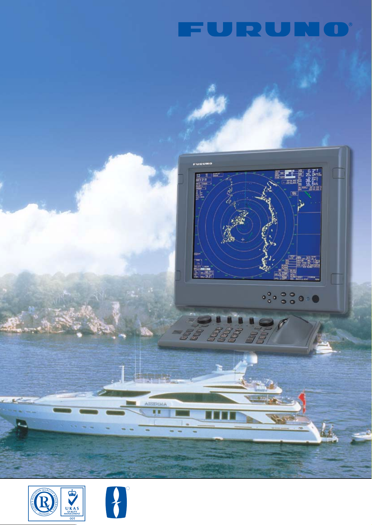
X/S-BAND BlackBox RADAR
DISPLAYING ARPA AND AIS TARGET INFORMATION
Models FAR-21x7-BB Series
Multi-color High Performance
Catalogue No. R-187
TRADE MARK REGISTERED
MARCA REGISTRADA
R
The future today with FURUNO's electronics technology.
FURUNO ELECTRIC CO., LTD.
9-52 Ashihara-cho, Nishinomiya City, Japan Phone: +81 (0)798 65-2111
Fax: +81 (0)798 65-4200, 66-4622 URL: www.furuno.co.jp
● 12, 25 kW T/R UP X-band, 30 kW S-band
● Supports non-interlaced SXGA (1280 x
1024) monitors with DVI-D input
● Presentation of very high-quality radar
image by employing new Digital Video
Interface (DVI) techniques
● Advanced signal processing for
improved detection in rough seas
● Up to four radar sets can be
interconnected in the network without
an extra device
● Standard ARPA plotting/tracking of 100
targets acquired automatically or
manually
● Displays up to 1,000 AIS-equipped
targets
● Easy operation by customizable
function keys, trackball/wheel palm
modules and rotary knobs
Photo: Control unit with
optional monitor MU-155C
Page 2
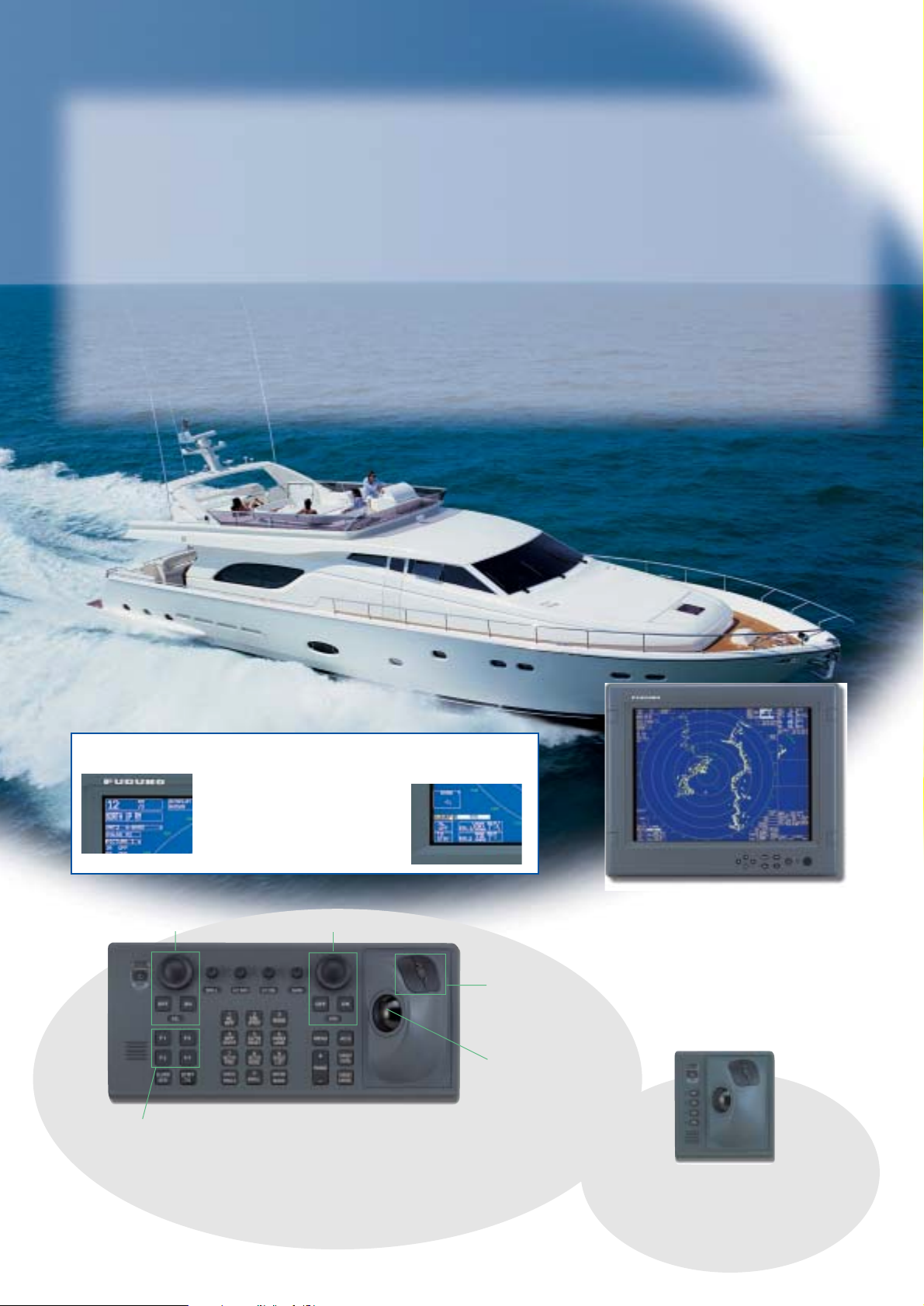
An ergonomically designed control unit features a trackball, scroll
wheel and operational push keys all organized in a functional and
logical layout. A well organized menu structure ensures that all
operation can be executed by trackball operation.
The finest BlackBox Radar you can own o
The finest BlackBox Radar you can own o
performance and a new user
performance and a new user
-friendly inte
-friendly inte
Trackball
(cursor control)
EBL control
VRM control
User Customizable Function Keys
Menu Item
Selector
(scroll wheel and
push buttons)
FURUNO's FAR-21x7BB series of X- and S-band BlackBox
Radars are constructed with our finest commercial grade
components and technology. These precision quality radar
systems are designed for high end vessels and offer
advanced target detection performance for safe navigation.
The Black Box Radars work with virtually any size multi-sync
SXGA (1280 x 1024) LCD or CRT monitor. Furuno also
offers a premier line of high-quality LCD monitors that are a
perfect compliment to the FAR-21x7BB Radar series.
FURUNO's MU-155C is a high-resolution LCD monitor that
features a variety of features and inputs, including 2 RGB
analog, 1 DVI-D and 3 NTSC/PAL video inputs. Connecting
a high-resolution SXGA monitor provides crisp radar images,
which are presented in selectable colors with a day and
night background for easy observation in any lighting
condition. Different colors are assigned for marks, symbols
and text for user-friendly operation.
Target detection is enhanced by employing sophisticated
signal processing techniques such as echo stretch, echo
average and anti-clutter functions. With useful functions
including ARPA, AIS target display, target trail, chart overlay
and radar map, the operator can improve navigation
efficiency and safety while cruising.
The radar antenna is available with 4, 6.5, or 8 ft radiator.
For the X-band, the rotation speed is selectable from 24 rpm
for standard radar or 42 rpm for high speed craft (HSC). The
S-band radar is available with the antenna radiator of 10 or
12 feet. The S-band radar assures target detection in
adverse weather where an X-band is heavily affected by sea
or rain clutter.
Trackball Control Unit
Use the Trackball Control Unit as a
remote control for the main Control
Unit, or as the main system controller
for those helms with limited space.
Control Unit
Various menu options can be easily selected
with the use of the trackball and scroll wheel.
All of the settings are assigned
to icons on the screen, which
can be easily selected with
single-hand operation.
Photo: MU-155C
The sunlight viewable MU-155C is
a 15" Color TFT LCD monitor and is
an ideal match for the FAR-21x7BB
series. The monitor features 2 RGB
analog, 1 DVI-D and 3 NTSC/PAL
video inputs. Use the NTSC/PAL
input for picture in picture (PIP)
Menu icons
Courtesy of FERRETTI
Page 3

ffers unmatched
ace
ace
The radar can be connected to an Ethernet network for
a variety of user requirements. Each of X- and S-band
radars can be interconnected without requiring extra
options. Up to four radar sets can be interchanged in
the network. In addition, the essential navigational
information including the electronic chart, L/L, COG,
SOG, STW, etc., can be shared in the network.
Radar System 1
Radar System 2
100 Base-TX Ethernet Network System
100 Base-TX
Other Radar Images, Chart Information,
COG, SOG, STW, etc.
Interswitch
Own Ship
data cell
AIS-equipped target
Automatically acquired targets
DATA Cell 1
Tracking data
Magnify
AIS
Information
Water temp,
Depth, Wind
This radar incorporates a
VideoPlotter that allows the
user to display electronic charts
(Navionics and Furuno Charts),
plot own and other ship’s track,
enable entry of waypoints/
routes, and make a radar map.
A chart may be overlaid with
the radar image. Optional card
reader required
FAR-2137S-BB: S-band, 30 kW, TR up
8 ft antenna
(4 or 6.5 ft also available)
AIS/ARPA
DATA Cell 2
Tracking data
DATA Cell 3
Tracking data
X-band antenna
S-band antenna
Chart Overlay
A variety of navigational information, own ship status, radar
plotting data, wind, water temperature and information from
other shipborne sensors are displayed in the cells.
Target Trails
Radar Map
The target trails feature
generates monotone or gradual
shading afterglow on all objects
on the display. This feature is
useful to show own ship
movement and other ship tracks
in a specific fishing operation.
The trail time is adjustable at 30
seconds intervals or continuous.
Up to 200 waypoints and
up to 30 routes can be
stored. Each route may
contain up to 30
waypoints. A radar map is
a combination of map
lines and marks. The radar
map has the capacity of
20,000 points for lines and
marks.
10 ft antenna
(12 ft also available)
100 Base-TX Ethernet Network System
FAR-2117-BB: X-band, 12 kW, TR up
FAR-2127-BB: X-band, 25 kW, TR up
Page 4

Antenna Radiators
1. Type Slotted waveguide array
2. Beamwidth and sidelobe attenuation
3. Rotation
RF Transceiver
1. Frequency
X-band: 9410 MHz ± 30 MHz
S-band: 3050 MHz ± 30 MHz
2. Output power
3. Pulselength/PRR
Range scale (nm)
Pulselength (µs) PRR (Hz)
0.125, 0.25 0.07 3000
0.5 0.07, 0.15 3000
0.75, 1.5 0.07, 0.15, 0.3 3000, 1500
3 0.15, 0.3, 0.5, 0.7 3000, 1500, 1000
6 0.3, 0.5, 0.7, 1.2 1500, 1000, 600
12, 24 0.5, 0.7, 1.2 1000, 600
48, 96 1.2 600
4. I.F. 60 MHz, Logarithmic
5. Bandwidth
Short pulse: 40 MHz
Middle pulse: 10 MHz
Long pulse: 3 MHz
Radar Display
1. Display Unit (Locally arranged)
Type: Non-interlaced, Multi-sync monitor (DVI-D)
Resolution SXGA (1280 x 1024 pixels)
2. Range scales and ring intervals (nm)
Range: .125, .25, .5, .75, 1.5, 3, 6, 12, 24, 48, 96
Ring: .025, .05, .1, .25, .25, .5, 1, 2, 4, 8, 16
3. Minimum range 30 m on 0.75 nm range scale
4. Range discrimination 30 m on 0.75 nm range scale
5. Range ring accuracy +0.2 %
6. Presentation modes Head-Up, Course-Up, North-Up,
North-Up TM
7. ARPA
Acquisition: 100 targets
Tracking: Automatic tracking of all acquired
targets in 0.1 to 32 nm
8. AIS Display (Data input from AIS is required)
Targets 1,000 targets
Power Supply (specify when ordering)
1. Processor Unit
24 VDC or 115/230 VAC, 1ø, 50/60 Hz,
7.6 A (FAR-2117-BB: 24 rpm at 24 VDC),
8.8 A (FAR-2127-BB: 24 rpm at 24 VDC)
440 VAC, 1ø, 50/60 Hz with RU-1803
2. Antenna Unit
FAR-2137S-BB:
200 VAC, 3ø, 50 Hz; 220 VAC, 3ø, 60 Hz; 380 VAC, 3ø, 50 Hz;
440 VAC, 3ø, 60 Hz; 110 VAC, 3ø, 60 Hz with RU-5693;
220 VAC, 3ø, 50 Hz with RU-6522;
440 VAC, 3ø, 50 Hz with RU-5466-1
EQUIPMENT LIST
Standard
1. Processor Unit RPU-013 1 unit
2. Control Unit RCU-014 or Trackball Control Unit RCU-015 1 unit
(Specify when ordering)
3. Antenna Unit with cable, 15/30/40/50 m 1 pc
4. Power Supply unit PSU-007 for FAR-2137S 1 unit
5. Standard Spare Parts and Installation Materials
Option
1. Performance Monitor PM-31 for X-band, PM-51 for S-band
2. Remote Control Unit RCU-016
3. Gyro Interface GC-10
4. DVI-Analog RGB Conversion Kit OP03-180
5. RGB Connector DSUB-BNC-1 (for VDR)
6. Chart/Memory Card Interface Unit CU-200-FAR
7. Transformer RU-1803/5466-1/5693/6522
8. Rectifier RU-3424/1746B
9. Junction Box RJB-001 (for expanded antenna cable, 100-300 m)
10. Antenna Cable RW-9600
11. Switching Hub HUB-100
04095Y Printed in Japan
FURUNO U.S.A., INC.
Camas, Washington, U.S.A.
Phone: +1 360-834-9300 Telefax: +1 360-834-9400
FURUNO (UK) LIMITED
Denmead, Hampshire, U.K.
Phone: +44 2392-230303 Telefax: +44 2392-230101
FURUNO FRANCE S.A.
Bordeaux-Mérignac, France
Phone: +33 5 56 13 48 00 Telefax: +33 5 56 13 48 01
FURUNO ESPANA S.A.
Madrid, Spain
Phone: +34 91-725-90-88 Telefax: +34 91-725-98-97
FURUNO DANMARK AS
Hvidovre, Denmark
Phone: +45 36 77 45 00 Telefax: +45 36 77 45 01
FURUNO NORGE A/S
Ålesund, Norway
Phone: +47 70 102950 Telefax: +47 70 127021
FURUNO SVERIGE AB
Västra Frölunda, Sweden
Phone: +46 31-7098940 Telefax: +46 31-497093
FURUNO FINLAND OY
Espoo, Finland
Phone: +358 9 4355 670 Telefax: +358 9 4355 6710
SPECIFICATIONS OF FAR-21x7-BB Series
X-Band
S-Band
Radiator Type
Length
Beamwidth(H)
Beamwidth(W)
Sidelobe
(within ± 10°)
Sidelobe (outside ± 10°)
XN-12AF
4 ft
1.9°
20°
-24 dB
-30 dB
XN-20AF
6.5 ft
1.23°
20°
-28 dB
-32 dB
XN-24AF
8 ft
0.95°
20°
-28 dB
-32 dB
SN-30AF
10 ft
2.3°
25°
-24 dB
-30 dB
S-band 10 ft radiator usable for a HSC
SN-36AF
12 ft
1.8°
25°
-24 dB
-30 dB
X-Band
S-Band
Rotation
Gear Box
Rotation
Gear Box
24 rpm
RSB-096
42 rpm
RSB-097
RSB-098 RSB-099 RSB-100
45 rpm
RSB-101 RSB-102
21/26 rpm
Output Power
Tr ansceiver
FAR-2117
12 kW
RTR-078
FAR-2127
25 kW
RTR-079
FAR-2137S
30 kW
RTR-080
SPECIFICATIONS SUBJECT TO CHANGE WITHOUT NOTICE
183 7.2"
350 13.8"
7
0.3"
385 15.2"
370 14.6"
25
1.0"
340 13.4"
380 15.0"
2- 7
410 16.1"
Antenna Unit
XN12AF: 33 kg 73 lb
XN-20AF: 39 kg 86 lb
XN-24AF: 42 kg 93 lb
SN-30AF: 135 kg 298 lb
SN-36AF: 142 kg 313 lb
Control Unit
RCU-014
Trackball Control
Unit RCU-015
Processor Unit
RPU-013
10 kg 22 lb
2.4 kg 5.3 lb
3.7 kg 8.2 lb
RW-9600, 15 m
RW-9600, 15 m
For FAR-2117-BB/2127-BB
Junction Box RJB-001
Junction Box RJB-001
200 VAC, 3 , 50 Hz*
220 VAC, 3 , 60 Hz
380 VAC, 3 , 50 Hz
440 VAC, 3 , 60 Hz
DVI
GPS Compass
AIS FA-100
Switching HUB
IEC 61162-1
Option or Shipyard Supply
RW-9600
15/30/
40/50 m
Performance Monitor
PM-51
Performance Monitor
PM-31
For FAR-2137S-BB
Antenna Unit
Power Supply Unit
PSU-007
250V-DPYCY-1.5
Processor
Unit
RPU-013
Power
Specify power supply when ordering
*Optional transformer required
Monitor
(1280 x1024 pixels)
Control Unit
RCU-014
Trackball Control Unit
RCU-015
03S-9610
10/20/30 m
10/20/30 m
10/20/30 m
Remote Control Unit
RCU-016
DVI-Analog RGB
Convirsion Kit
Gyro Interface
GC-10
IEC 61162-1
IEC 61162-1
RW-4846
Gyro Converter
AD-100
Ethernet
100Base-TX
Chart/Menory Card
Interface Unit
CU-200
FAR-21x7/28x7
GPS Navigator
ECDIS FEA-21x7/28x7
INS VOYAGER
Gyro Compass
115 VAC, 1 , 50/60 Hz
230 VAC, 1 , 50/60 Hz
440 VAC, 1 , 50/60 Hz*
24 VDC
70 - 270 m
INTERCONNECTION DIAGRAM
XN-12AF:1260 49.6"
124 4.9"
XN-20AF: 2040 80.3"
XN-24AF: 2550 100.4"
137 5.4"
555 21.9"
18 0.7"
468 18.4"
SN-36AF: 3765 148.2"
SN-30AF: 3090 121.7"
421 16.6"
184 7.2"
432 17.0"
300 11.8"
110
4.3"
105
4.1"
137
5.4"
530 20.9"
100
3.9"
4- 15
105
4.1"
286 11.3"250 9.8"
570 22.4"
18 0.7"
378 14.9"
275 10.8"
110
8- 15
4.3"
432 17.0"
561 22.1"
432 17.0"
350 13.8"
468 18.4"
300 11.8"
710 28.0"
420 16.5"
308 12.1"
398 15.7"
110 4.3"
160 6.3"
4- 15
136 5.4"
4- 4
180 7.1"
4- 4
92 3.6"
136 5.4"
180 7.1"
89 3.5"
39 1.5"
35 1.4"
 Loading...