

Page 1

OPERATOR'S MANUAL
MARINE RADAR
FAR-2807(-D) Series
MODEL
FAR-2107(-BB,-D) Series
(Fishing Specification)
www.furuno.co.jp
Page 2

9-52 Ashihara-cho,
*
00017083511
**00017083511
*
Nishinomiya, 662-8580, JAPAN
Telephone : +81-(0)798-65-2111
Fax :+81-(0)798-65-4200
The paper used in this manual
is elemental chlorine free.
・FURUNO Authorized Distributor/Dealer
All rights reserved.
Pub. No. OME-35220-B
(DAMI ) FAR-21X7/28X7(FISH)
Printed in Japan
A : JAN 2011
.
B : FEB . 18, 2011
*00017083511**00017083511*
* 0 0 0 1 7 0 8 3 5 1 1 *
Page 3

IMPORTANT NOTICES
General
• The operator of this equipment must read and follow the descriptions in this manual.
Wrong operation or maintenance can cancel the warranty or cause injury.
• Do not copy any part of this manual without written permission from FURUNO.
• If this manual is lost or worn, contact your dealer about replacement.
• The contents of this manual and equipment specifications can change without notice.
• The example screens (or illustrations) shown in this manual can be different from the
screens you see on your display. The screens you see depend on your system
configuration and equipment settings.
• Save this manual for future reference.
• Any modification of the equipment (including software) by persons not authorized by
FURUNO will cancel the warranty.
• All brand and product names are trademarks, registered trademarks or service marks of
their respective holders.
How to discard this product
Discard this product according to local regulations for the disposal of industrial waste. For
disposal in the USA, see the homepage of the Electronics Industries Alliance
(http://www.eiae.org/) for the correct method of disposal.
How to discard a used battery
Some FURUNO products have a battery(ies). To see if your product has a battery, see the
chapter on Maintenance. Follow the instructions below if a battery is used. Tape the + and terminals of battery before disposal to prevent fire, heat generation caused by short circuit.
In the European Union
The crossed-out trash can symbol indicates that all types of
batteries must not be discarded in standard trash, or at a trash
site. Take the used batteries to a battery collection site
according to your national legislation and the Batteries Directive
2006/66/EU.
In the USA
The Mobius loop symbol (three chasing arrows) indicates that
Ni-Cd and lead-acid rechargeable batteries must be recycled.
Take the used batteries to a battery collection site according to
local laws.
Cd
Ni-Cd Pb
In the other countries
There are no international standards for the battery recycle symbol. The number of symbols
can increase when the other countries make their own recycling symbols in the future.
i
Page 4

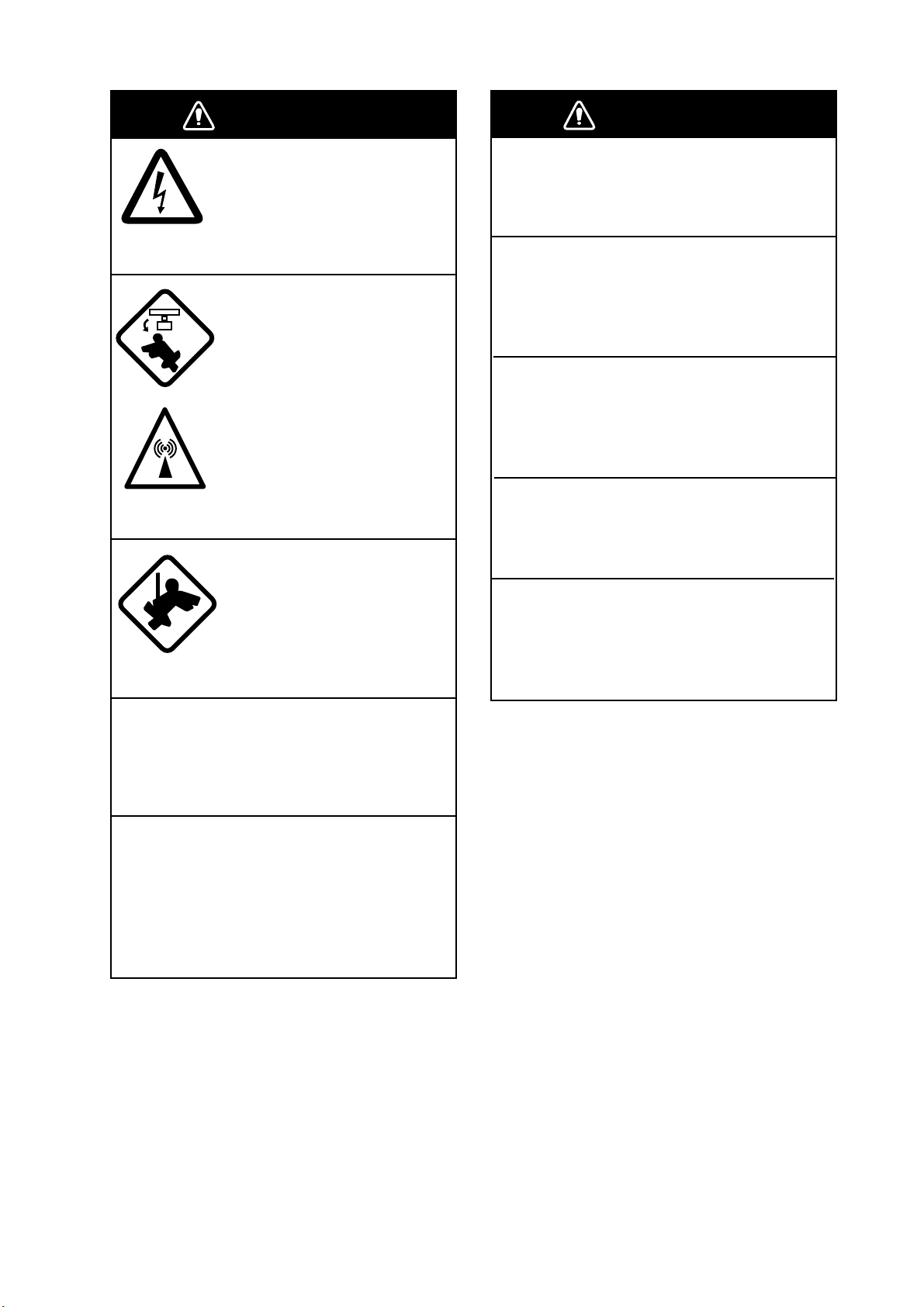
SAFETY INSTRUCTIONS
WARNING
Radio Frequency Radiation Hazard
The radar antenna emits electromagnetic radio frequency (RF) energy which can be harmful,
particularly to your eyes. Never look directly into the antenna aperture from a close distance
while the radar ius in operation or eexpose yourself to the transmitting antenna at a close
distance. Distances at which RF radiation level of 100, 50 and 10 W/m are given in the table
below.
Note: If the antenna unit is installed at a close distance in front of the wheel house, your
administration may require halt of transmission within a certain sector of antenna revolution.
This is possible. Ask your FURUNO representive or dealer to provide this feature.
2
Distance to
100 W/m
Radar model
FAR-2127/2827
FAR-2127/2827
FAR-2127/2827
FAR-2117/2817
FAR-2117/2817
FAR-2117/2817
FAR-2137S
FAR-2137S
FAR-2157
FAR-2157
FAR-2167DS
FAR-2167DS
FAR-2827W
FAR-2827W
FAR-2837S
FAR-2837S
FAR-2837SW
*1
XN12AF: 120cm, XN20AF: 198cm, XN24AF: 243cm, XN4A: 257cm, XN5A: 321cm,
SN30AF: 309cm, SN36AF: 377cm
*2
Or MAF1425B
Trans. Unit
RTR-079
RTR-079
RTR-079
RTR-078
RTR-078
RTR-078
RTR-080
RTR-080
RTR-083
RTR-083
RTR-084
RTR-084
RTR-081
RTR-081
RTR-080
RTR-080
RTR-082
Magnetron
MG5436
MG5436
MG5436
MG4010
MG4010
MG4010
MG5223F
MG5223F
9M31
9M31
MG5240F
MG5240F
MG5436
MG5436
MG5223F
MG5223F
MG5223F
*2
*2
*2
Antenna
XN12AF
XN20AF
XN24AF
XN12AF
XN20AF
XN24AF
SN30AF
SN36AF
XN4A
XN5A
SN30AF
SN36AF
XN20AF
XN24AF
SN30AF
SN36AF
SN36AF
0.90m
0.50m
0.20m
0.30m
0.10m
0.10m
0.10m
0.10m
1.20m
1.10m
0.60m
0.40m
2.20m
1.50m
0.10m
0.10m
1.00m
2
point
Distance to
10 W/m
13.00m
11.50m
2
point
9.00m
4.60m
3.30m
3.70m
2.20m
1.50m
2.40m
2.00m
13.6m
12.3m
8.90m
7.40m
2.40m
2.00m
8.50m
ii
Page 5
SAFETY INSTRUCTIONS
WARNING
ELECTRICAL SHOCK HAZARD
Do not open the equipment.
Only qualified personnel
should work inside the
equipment.
Turn off the radar power
switch before servicing the
antenna unit. Post a warning sign near the switch
indicating it should not be
turned on while the antenna
unit is being serviced.
Prevent the potential risk of
being struck by the rotating
antenna and exposure to
RF radiation hazard.
Wear a safety belt and hard
hat when working on the
antenna unit.
Serious injury or death can
result if someone falls from
the radar antenna mast.
WARNING
Use the proper fuse.
Use of a wrong fuse can result in damage
to the equipment or cause fire.
Keep heater away from equipment.
Heat can alter equipment shape and melt
the power cord, which can cause fire or
electrical shock.
Do not place liquid-filled containers
near the equipment.
Fire or electrical shock can result if a liquid
spills into the equipment.
Do not operate the equipment with wet
hands.
Electrical shock can result.
Before servicing the radar, turn off
the appropriate external breaker.
Power is not removed from the radar simply
by turning off its power switch.
Do not disassemble or modify the
equipment.
Fire, electrical shock or serious injury can
result.
Immediately turn off the power at the
ship's mains switchboard if water
leaks into the equipment or the equipment is emitting smoke or fire.
Continued use can cause fatal damage to
the equipment.
iii
Page 6
SAFETY INSTRUCTIONS
WARNING
No one navigational aid should be relied
upon for the safety of vessel and crew.
The navigator has the responsibility to
check all aids available to confirm
position. Electronic aids are not
a substitute for basic navigational
principles and common sense.
• This ARP automatically tracks
automatically or manually acquired radar
targets and calculates their courses and
speeds, indicating them by vectors. Since
the data generated by the auto plotter
are based on what radar targets are
selected, the radar must always be
optimally tuned for use with the auto
plotter, to ensure required targets will not
be lost or unwanted targets such as sea
returns and noise will not be acquired
and tracked.
• A target does not always mean a land mass, reef, ships or other surface vessels
but can imply returns from sea surface
and clutter. As the level of clutter changes
with environment, the operator should
properly adjust the A/C SEA, A/C RAIN
and GAIN controls to be sure target
echoes are not eliminated from the
radar screen.
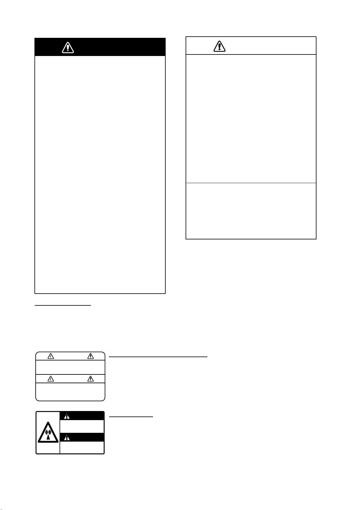
WARNING LABEL
Warning labels are attached to the
equipment. Do not remove any label.
If a label is missing or damaged,
contact a FURUNO agent or dealer
about replacement.
CAUTION
The plotting accuracy and response of
this ARP meets IMO standards.
Tracking accuracy is affected by the
following:
• Tracking accuracy is affected by course
change. One to two minutes is required to
restore vectors to full accuracy after an
abrupt course change. (The actual
amount depends on gyrocompass
specifications.)
• The amount of tracking delay is inversely
proportional to the relative speed of the
target. Delay is on the order of 15—30
seconds for high relative speed; 30—60
seconds for low relative speed.
The data generated by ARP, AIS and
video plotter are intended for
reference only.
Refer to official nautical charts for
detailed and up-to-date information.
WARNING
To avoid electrical shock, do not
remove cover. No user-serviceable
parts inside.
WARNING
Radiation hazard. Only qualified
personnel should work inside scanner.
Confirm that TX has stopped before
opening scanner.
iv
DISPLAY UNIT, PROCESSOR UNIT
Name: Warning Label (1)
Type: 86-003-1011-1
Code No.: 100-236-231
ANTENNA UNIT
Name: Radiation Warning Label
Type:
Code No.: 100-266-890
03-142-3201-0
Page 7

TABLE OF CONTENTS
FOREWORD ........................................................................................................ xi
PROGRAM NUMBER ........................................................................................ xiii
SYSTEM CONFIGURATION.............................................................................. xiv
SPECIFICATIONS...........................................................................................SP-1
1. RADAR OPERATION.................................................................................... 1-1
1.1 Turning on the Power .................................................................................................. 1-1
1.2 Transmitter ON ............................................................................................................ 1-1
1.3 Control Unit ................................................................................................................. 1-3
1.4 Main Menu................................................................................................................... 1-5
1.5 Operation by the On-Screen Boxes ............................................................................ 1-7
1.6 Cursor Menu.............................................................................................................. 1-10
1.7 Monitor Brilliance ........................................................................................................1-11
1.8 Display Modes ........................................................................................................... 1-12
1.9 On-Screen Boxes and Markers ................................................................................. 1-13
1.10 Tuning the Receiver .................................................................................................. 1-15
1.10.1 Choosing the tuning method........................................................................... 1-15
1.10.2 Initializing tuning ............................................................................................. 1-15
1.10.3 Automatic tuning ............................................................................................. 1-16
1.10.4 Manual tuning ................................................................................................. 1-16
1.11 Aligning Heading with Gyrocompass......................................................................... 1-16
1.12 Presentation Modes................................................................................................... 1-17
1.12.1 Choosing presentation mode.......................................................................... 1-17
1.12.2 Description of presentation modes ................................................................. 1-18
1.13 Entering Own Ship's Speed....................................................................................... 1-22
1.13.1 Automatic speed input by log or GPS navigator ............................................. 1-22
1.13.2 Manual speed input ........................................................................................ 1-23
1.14 Choosing a Range Scale........................................................................................... 1-23
1.15 Choosing a Pulselength ............................................................................................ 1-24
1.15.1 Choosing a pulselength .................................................................................. 1-24
1.15.2 Changing pulselength..................................................................................... 1-25
1.16 Adjusting the Sensitivity ............................................................................................ 1-26
1.17 Reducing Sea Clutter ................................................................................................ 1-27
1.17.1 Choosing method of adjustment ..................................................................... 1-27
1.17.2 Automatic reduction of sea clutter .................................................................. 1-27
1.17.3 Manual reduction of sea clutter....................................................................... 1-28
1.18 Reducing Rain Clutter ............................................................................................... 1-29
1.18.1 Automatic reduction of rain clutter .................................................................. 1-29
1.18.2 Manual reduction of rain clutter ...................................................................... 1-29
1.19 Measuring Range ...................................................................................................... 1-31
1.19.1 Showing, hiding the fixed range rings............................................................. 1-31
1.19.2 Measuring range by the variable range marker (VRM)................................... 1-32
1.19.3 VRM unit of measurement (B and C types) .................................................... 1-33
1.19.4 TTG to VRM indication ................................................................................... 1-33
1.20 Measuring Bearing .................................................................................................... 1-34
1.20.1 Measuring bearing .......................................................................................... 1-34
1.20.2 True or relative bearing................................................................................... 1-35
1.21 Collision Assessment by Offset EBL ......................................................................... 1-36
1.21.1 How to assess risk of collision by the offset EBL............................................ 1-36
v
Page 8

TABLE OF CONTENTS
1.21.2 Point of reference for origin point of offset EBL...............................................1-37
1.22 Measuring Range and Bearing Between Two Targets ...............................................1-38
1.23 Target Alarm...............................................................................................................1-39
1.23.1 How to set a target alarm ................................................................................1-39
1.23.2 Acknowledging the target alarm ......................................................................1-40
1.23.3 Deactivating a target alarm..............................................................................1-40
1.23.4 Target alarm attributes.....................................................................................1-41
1.24 Off-Centering the Display...........................................................................................1-42
1.25 Interference Rejector..................................................................................................1-43
1.26 Echo Stretch...............................................................................................................1-43
1.27 Echo Averaging..........................................................................................................1-44
1.28 Noise Rejector............................................................................................................1-45
1.29 Wiper..........................................................................................................................1-46
1.30 Target Trails................................................................................................................1-47
1.30.1 True or relative trails........................................................................................1-47
1.30.2 Trail time..........................................................................................................1-48
1.30.3 Trail gradation..................................................................................................1-48
1.30.4 Saving, copying target trails ............................................................................1-49
1.30.5 Trail level .........................................................................................................1-50
1.30.6 Narrow trails (B, C and W types).....................................................................1-50
1.30.7 Longer trails (B, C and W types) .....................................................................1-51
1.30.8 Temporarily removing trails from the display ...................................................1-51
1.30.9 Trail stabilization in true motion .......................................................................1-51
1.30.10 Erasing trails..................................................................................................1-51
1.30.11 Preventing sea clutter in true trails ................................................................1-52
1.31 PI (Parallel Index) Lines .............................................................................................1-52
1.31.1 Displaying, erasing PI lines .............................................................................1-52
1.31.2 Adjusting PI line orientation, PI line interval ....................................................1-53
1.31.3 PI line bearing reference .................................................................................1-53
1.31.4 Maximum number of PI lines to display...........................................................1-54
1.31.5 PI line orientation.............................................................................................1-54
1.31.6 Resetting PI lines ............................................................................................1-54
1.32 Origin Mark.................................................................................................................1-55
1.32.1 Entering origin marks ......................................................................................1-55
1.32.2 Origin mark stabilization ..................................................................................1-57
1.32.3 Deleting individual origin marks.......................................................................1-57
1.33 Zoom..........................................................................................................................1-58
1.34 Markers ......................................................................................................................1-59
1.34.1 Heading line ....................................................................................................1-59
1.34.2 Stern marker....................................................................................................1-59
1.34.3 North marker ...................................................................................................1-59
1.34.4 Own ship symbol .............................................................................................1-60
1.34.5 Barge marker...................................................................................................1-61
1.34.6 INS marker ......................................................................................................1-61
1.35 Automatic Picture Setup According to Navigation Purpose .......................................1-62
1.35.1 Selecting a picture setup option ......................................................................1-64
1.35.2 Programming and saving picture setups .........................................................1-64
1.35.3 Restoring user settings....................................................................................1-66
1.35.4 Restoring default picture setup options ...........................................................1-66
1.35.5 Disabling unnecessary picture setups.............................................................1-67
1.36 Function Keys ............................................................................................................1-68
1.36.1 Activating function keys...................................................................................1-68
1.36.2 Programming function keys.............................................................................1-68
vi
Page 9

TABLE OF CONTENTS
1.37 Ship’s Position........................................................................................................... 1-72
1.38 Second-trace Echoes ................................................................................................ 1-74
1.39 Brilliance of Screen Data........................................................................................... 1-75
1.40 Watch Alarm .............................................................................................................. 1-76
1.41 Nav Data ................................................................................................................... 1-77
1.42 Text Window .............................................................................................................. 1-79
1.43 Customizing Operation.............................................................................................. 1-81
1.44 Alert Box.................................................................................................................... 1-83
1.44.1 Alarm description ............................................................................................ 1-84
1.44.2 Alarm list ......................................................................................................... 1-87
1.44.3 Outputting alarm signals ................................................................................. 1-88
1.44.4 Primary alarm ................................................................................................. 1-89
1.45 Interswitch ................................................................................................................. 1-90
1.45.1 Displaying antenna information ...................................................................... 1-90
1.45.2 Presetting antenna and display combinations ................................................ 1-91
1.45.3 Selecting an antenna...................................................................................... 1-93
1.46 Cursor Data ............................................................................................................... 1-93
1.47 Performance Monitor................................................................................................. 1-94
1.47.1 Activating, deactivating the performance monitor........................................... 1-94
1.47.2 Checking radar performance .......................................................................... 1-94
1.48 Own Ship Marker....................................................................................................... 1-96
1.49 Color and Brilliance Sets ........................................................................................... 1-97
1.49.1 Selecting color and brilliance set .................................................................... 1-97
1.49.2 Presetting color and brilliance set................................................................... 1-97
1.50 Reference Position .................................................................................................... 1-99
1.51 Switching Hub HUB-100 (option) ............................................................................ 1-101
1.52 Anchor Watch.......................................................................................................... 1-102
1.53 Drop Mark................................................................................................................ 1-103
1.53.1 Activating the drop mark feature................................................................... 1-103
1.53.2 Inscribing a drop mark .................................................................................. 1-104
1.53.3 Erasing a drop mark ..................................................................................... 1-104
1.54 Sub Monitor (A, B, C and W types) ......................................................................... 1-105
1.55 Net Cursor ............................................................................................................... 1-106
1.55.1 Activating the net cursor ............................................................................... 1-106
1.55.2 Setting net cursor dimensions, adjusting net cursor orientation ................... 1-107
2. RADAR OBSERVATION ...............................................................................2-1
2.1 General........................................................................................................................ 2-1
2.1.1 Minimum and maximum ranges........................................................................ 2-1
2.2 False Echoes............................................................................................................... 2-3
2.3 SART (Search and Rescue Transponder)................................................................... 2-5
2.3.1 SART description.............................................................................................. 2-5
2.3.2 Showing SART marks on the radar display ...................................................... 2-6
2.3.3 General remarks on receiving SARTs............................................................... 2-7
2.4 RACON ....................................................................................................................... 2-8
2.5 Radar Target Enhancer (RTE)..................................................................................... 2-8
3. TARGET TRACKING (TT)............................................................................. 3-1
3.1 Usage Precautions ...................................................................................................... 3-1
3.2 Controls for TT............................................................................................................. 3-2
3.3 Activating, Deactivating TT.......................................................................................... 3-3
3.4 Entering Own Ship's Speed......................................................................................... 3-3
3.4.1 Echo-referenced speed input............................................................................ 3-3
3.5 Automatic Acquisition .................................................................................................. 3-5
vii
Page 10

TABLE OF CONTENTS
3.5.1 Enabling auto acquisition ..................................................................................3-5
3.5.2 Terminating tracking of targets (including reference targets).............................3-6
3.6 Manual Acquisition .......................................................................................................3-7
3.6.1 Setting manual acquisition conditions ...............................................................3-7
3.6.2 Manually acquiring targets.................................................................................3-7
3.7 Lost Target ...................................................................................................................3-9
3.7.1 Setting the lost target filter.................................................................................3-9
3.7.2 Enabling, disabling the lost target alarm............................................................3-9
3.8 TT Symbols and Attributes.........................................................................................3-10
3.8.1 TT symbols......................................................................................................3-10
3.8.2 Choosing TT symbol (B, C and W types) ........................................................ 3-11
3.8.3 TT symbol brilliance.........................................................................................3-11
3.8.4 TT symbol color...............................................................................................3-12
3.9 Displaying Target Data...............................................................................................3-13
3.9.1 Displaying target data......................................................................................3-13
3.9.2 Target list .........................................................................................................3-15
3.10 Vector Modes.............................................................................................................3-16
3.10.1 Description of vectors......................................................................................3-16
3.10.2 Vector mode and length ..................................................................................3-17
3.11 Past Position Display .................................................................................................3-18
3.11.1 Displaying and erasing past position points, choosing past
position plot interval.........................................................................................3-18
3.11.2 Past position display attributes........................................................................3-19
3.11.3 Past position display mode..............................................................................3-19
3.11.4 Stabilization in true mode ................................................................................3-20
3.12 Set and Drift ...............................................................................................................3-20
3.13 TT Collision Alarm (CPA, TCPA) ................................................................................3-21
3.13.1 Setting the CPA and TCPA ranges ..................................................................3-21
3.13.2 Acknowledging the TT collision alarm .............................................................3-22
3.14 Acquisition Zone.........................................................................................................3-22
3.14.1 Activating an acquisition zone .........................................................................3-22
3.14.2 Sleeping, deactivating an acquisition zone......................................................3-23
3.14.3 Acknowledging the alarm ................................................................................3-23
3.14.4 Acquisition zone reference ..............................................................................3-24
3.14.5 Acquisition zone shape and stabilization.........................................................3-24
3.15 TT System Messages ................................................................................................3-25
3.16 Trial Maneuver ...........................................................................................................3-26
3.16.1 Types of trial maneuvers .................................................................................3-26
3.16.2 Performing a trial maneuver ............................................................................3-27
3.16.3 Terminating a trial maneuver ...........................................................................3-29
3.17 TT Performance Test..................................................................................................3-30
3.18 Criteria for Selecting Targets for Tracking..................................................................3-32
3.19 Factors Affecting TT Functions...................................................................................3-34
4. AIS OPERATION........................................................................................... 4-1
4.1 Controls for AIS............................................................................................................4-1
4.2 Showing, Hiding the AIS Display..................................................................................4-2
4.3 AIS Display Filter..........................................................................................................4-4
4.4 Activating Targets.........................................................................................................4-5
4.4.1 Activating specific targets manually...................................................................4-5
4.4.2 Activating all targets ..........................................................................................4-5
4.5 How to Sleep Targets ...................................................................................................4-6
4.5.1 Sleeping an individual target .............................................................................4-6
viii
Page 11

TABLE OF CONTENTS
4.5.2 Sleeping all targets ........................................................................................... 4-6
4.6 Setting Up for a Voyage .............................................................................................. 4-7
4.7 Target Data.................................................................................................................. 4-9
4.7.1 Basic target data............................................................................................... 4-9
4.7.2 Detailed target data......................................................................................... 4-10
4.7.3 Removing a target data display ...................................................................... 4-10
4.7.4 Canceling tracking on a target from target data display.................................. 4-10
4.8 AIS Symbol Attributes.................................................................................................4-11
4.8.1 AIS symbol brilliance .......................................................................................4-11
4.8.2 AIS symbol size and color ...............................................................................4-11
4.9 Past Position Display................................................................................................. 4-12
4.9.1 Past position plot interval................................................................................ 4-12
4.9.2 Past position points......................................................................................... 4-13
4.9.3 Past position display motion ........................................................................... 4-13
4.9.4 Stabilization in true motion.............................................................................. 4-13
4.10 Lost Target................................................................................................................. 4-14
4.10.1 Lost target filter ............................................................................................... 4-14
4.10.2 Enabling, disabling the lost target alarm......................................................... 4-15
4.11 ROT Setting............................................................................................................... 4-16
4.12 AIS Collision Alarm (CPA, TCPA).............................................................................. 4-17
4.12.1 Setting the CPA and TCPA ranges.................................................................. 4-17
4.12.2 Enabling, disabling the AIS collision alarm ..................................................... 4-17
4.12.3 Limiting the function of the collision alarm...................................................... 4-18
4.13 Association of TT and AIS Targets............................................................................. 4-19
4.14 Own Ship’s Data........................................................................................................ 4-21
4.15 Messages .................................................................................................................. 4-22
4.15.1 Creating, saving messages ............................................................................ 4-22
4.15.2 Transmitting messages................................................................................... 4-23
4.15.3 Viewing messages.......................................................................................... 4-24
4.16 AIS System Messages .............................................................................................. 4-26
5. VIDEO PLOTTER OPERATION.................................................................... 5-1
5.1 General........................................................................................................................ 5-1
5.2 Display Modes ............................................................................................................. 5-1
5.3 Presentation Modes..................................................................................................... 5-2
5.4 Radar Map................................................................................................................... 5-3
5.4.1 Showing, hiding the radar map display............................................................. 5-3
5.4.2 Inscribing radar map marks and lines............................................................... 5-4
5.5 Erasing Radar Map Marks and Lines .......................................................................... 5-6
5.5.1 Erasing individual radar map marks and lines .................................................. 5-6
5.5.2 Erasing all radar map marks and lines ............................................................. 5-7
5.6 Radar Map Corrections ............................................................................................... 5-8
5.6.1 Radar map correction ....................................................................................... 5-8
5.6.2 Cursor data correction ...................................................................................... 5-8
5.7 Chart Cards (A, B, C and W types) ............................................................................. 5-9
5.7.1 Displaying a chart ............................................................................................. 5-9
5.7.2 Chart position correction................................................................................. 5-10
5.7.3 Correcting cursor data .................................................................................... 5-10
5.7.4 Chart land color (B, C and W types) ................................................................5-11
5.8 Hiding, Showing Graphics on the Video Plotter Display ......................................... 5-12
5.9 Track.......................................................................................................................... 5-13
5.9.1 Plotting own ship’s track ................................................................................. 5-13
5.9.2 Plotting interval for other ships' tracks (A, B, C and W types) ........................ 5-14
ix
Page 12

TABLE OF CONTENTS
5.9.3 Auto target track (A, B, C and W types) ..........................................................5-15
5.9.4 Choosing track color (A, B, C and W types)....................................................5-15
5.9.5 Erasing track from the menu, on the screen....................................................5-16
5.9.6 Erasing track with the cursor ...........................................................................5-17
5.10 Waypoints ..................................................................................................................5-18
5.10.1 Entering waypoints ..........................................................................................5-18
5.10.2 Editing, erasing waypoints from the menu.......................................................5-20
5.10.3 Erasing waypoints ...........................................................................................5-21
5.10.4 Waypoint list ....................................................................................................5-22
5.10.5 Displaying waypoint name and number...........................................................5-23
5.11 Nav Lines ...................................................................................................................5-24
5.11.1 Entering a new nav line ...................................................................................5-24
5.11.2 Editing a nav line .............................................................................................5-25
5.11.3 Nav line list ......................................................................................................5-26
5.11.4 Erasing a nav line............................................................................................5-27
5.11.5 Setting up nav lines .........................................................................................5-28
5.11.6 Displaying nav line, waypoint mark .................................................................5-30
5.12 Recording Data ..........................................................................................................5-32
5.12.1 Initializing memory (RAM) cards......................................................................5-32
5.12.2 Recording data ................................................................................................5-33
5.13 Replaying Data...........................................................................................................5-35
5.14 Deleting Files .............................................................................................................5-36
6. MAINTENANCE, TROUBLESHOOTING......................................................6-1
6.1 Periodic Maintenance Schedule...................................................................................6-2
6.2 Life Expectancy of Major Parts ....................................................................................6-3
6.3 Replacing the Fuse ......................................................................................................6-4
6.4 Replacement of Battery on GC Board..........................................................................6-4
6.5 Trackball Maintenance .................................................................................................6-5
6.6 Easy Troubleshooting...................................................................................................6-6
6.7 Advanced-level Troubleshooting ..................................................................................6-7
6.8 Diagnostics.................................................................................................................6-10
APPENDIX ...................................................................................................... AP-1
1. Menu Tree ..................................................................................................................... AP-1
2. Digital Interface..............................................................................................................AP-8
3. Longitude Error Table (on 96 nm range scale) ............................................................ AP-29
INDEX............................................................................................................... IN-1
Declaration of conformity
x
Page 13
FOREWORD
A Word to the Owner of
FAR-2807(-D)/FAR-2107(-BB,-D) Series
Congratulations on your choice of the FURUNO FAR-2807(-D)/FAR-2107(-BB,-D) Series
Radar. We are confident you will see why FURUNO has become synonymous with quality
and reliability.
For 60 years FURUNO Electric Company has enjoyed an enviable reputation for innovative
and dependable marine electronics equipment. This dedication to excellence is furthered by
our extensive global network of agents and dealers.
Your radar is designed and constructed to meet the rigorous demands of the marine
environment. However, no machine can perform its intended function unless installed,
operated and maintained properly. Please carefully read and follow the recommended
procedures for operation and maintenance.
We would appreciate hearing from you, the end-user, about whether we are achieving our
purposes.
Thank you for considering and purchasing FURUNO equipment.
Features
• High-resolution 19-inch (FAR-2107-D), 20.1-inch LCD (FAR-2107(-BB)) or 23.1-inch LCD
(FAR-2807(-D)).
• This series of radar are available in the models shown in the table below. 2107 series
also available in "–BB", "-D" configuration. 2807 series also available in "–D"
configuration. For example, FAR-2117-BB, FAR-2117-D.
Model Band Monitor Output TR config.
10kW
FAR-2117 17 inch
FAR-2117 10kW
FAR-2127 25kW
FAR-2157
FAR-2817 10kW
FAR-2827 25kW
FAR-2827W
FAR-2137S 30kW
FAR-2167DS
FAR-2837S 30kW
FAR-2837SW
X-band
S-band
20.1 inch
23.1 inch
20.1 inch
23.1 inch
10kW
25kW
25kW
UP
50kW
25kW DOWN
60kW
30kW DOWN
UP
xi
Page 14

FOREWORD
• Two types of trackball-equipped control units are available: RCU-014 (full keyboard) and
the RCU-015 (palm control). The trackball is easy to use thanks to the ergonomically
designed palm rest.
• Simplified operation with point-and-click menu operation.
• All functions are accessible by using the trackball alone.
• Applicable to HSC (High Speed Craft)
• TT, AIS, Radar Plotter and Interswitch supplied as standard.
• Meets the requirements in IEC 62388 (Maritime navigation and radiocommunication
equipment and systems - Shipborne radar - Performance requirements, methods of
testing and required test results).
• Meets the requirements in IMO MSC.192(79).
• Meets the requirements in IEC 62288 (Maritime navigation and radiocommunication
equipment and systems - Presentation of navigation-related information on shipborne
navigational displays - General requirements, methods of testing and required test
results).
• Target alarm watches for targets entering or exiting an alarm zone
• TC PA/CPA alarms
• Electronic parallel index lines
• 42 rpm antenna for high speed craft
xii
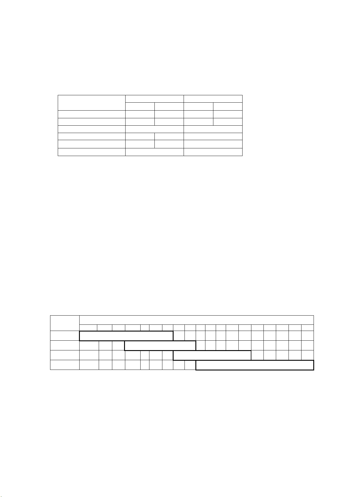
Page 15

Radar Type and Function Availability
This radar series is available in five specification types to meet the requirements of Authorities,
and function availability depends on specification type. The table below shows those functions
that have limited availability. This manual provides descriptions for all functions in this radar
series, and we have endeavored to denote in the text those functions that have limited
availability. For detailed information on function availability, see the menu tree in the Appendix.
• IMO: IMO compliant
• A: Near-IMO specifications
• B: Non-Japanese fishing vessels
• C: Japanese fishing vessels
• W: Washington state (USA) ferry
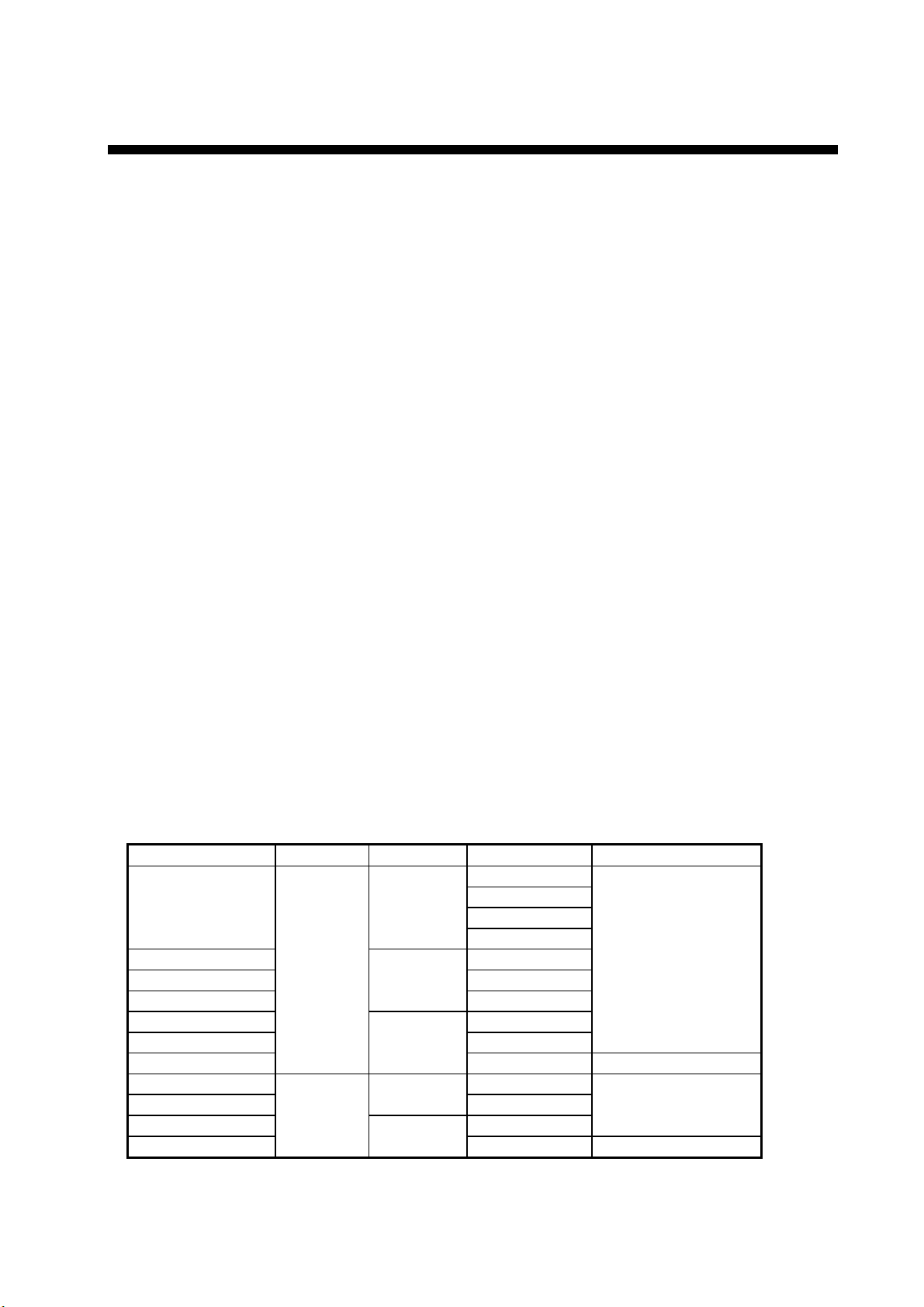
Specification type and function availability
Function
TT symbol
selection
TT w/o gyro No No Yes Yes Yes
Color echo No No Yes Yes Yes
Mark w/line No No Yes Yes Yes
Pop-up
guidance
Range 0.125, 0.25,
Range unit nm only nm only nm, sm, km,
Stern-up No Yes Yes Yes Ye s
Trails-Narrow No No Yes Yes Yes
Track-Other
ship
Waypoint
mark
IMO A B C W
No No Yes Yes Yes
No No Yes Yes Yes
Same as IMO 0.125, 0.25,
0.5, 0.75, 1.5,
3, 6, 12, 24,
48, 96
No Yes Yes Yes Ye s
No No Yes Yes Yes
Type
0.5, 0.75, 1,
1.5, 2, 3, 4, 6,
8, 12, 16, 24,
32, 48, 96,
120
kyd
Same as B Same as B
nm, sm, km,
kyd
nm, sm, km,
kyd
xiii
Page 16

PROGRAM NUMBER
PC Board Program No. Version No.
MAIN 035-9204 03.** (Merchant)
RFC 035-9202 01.**
KEY(REMOTE) 035-9203 01.**
ARPA 035-9212 01.**
** Minor modification
xiv
Page 17
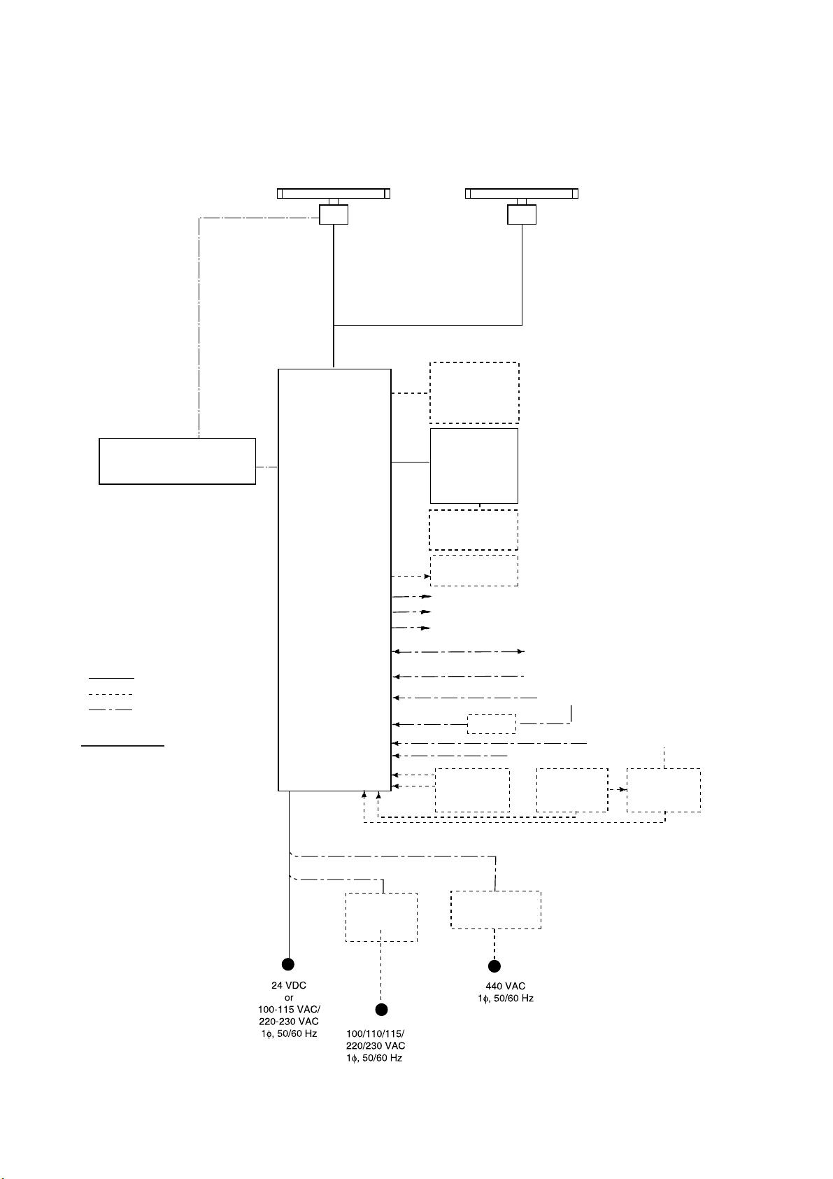
SYSTEM CONFIGURATION
See page xix for detailed information about antenna units and radiators.
With FURUNO-supplied monitor
FAR-2137S(-BB,-D)/2837S(-D)/2837SW(-D)
(Performance Monitor PM-51* built in)
POWER SUPPLY UNIT
PSU-007
(For FAR-2137S(-BB,-D)/2837S(-BB,-D))
POWER SUPPLY UNIT
(For FAR-2827W(-D)/2837SW(-D))
* Russian flag only
OR
PSU-011*
ANTENNA UNIT
Waveguide or
Coax cable
(For FAR-2837SW(-D))
TRANSCEIVER UNIT
RTR-082
For FAR-2837SW(-D)
PROCESSOR UNIT
RPU-013
FAR-2117(-BB,-D)/2127(-BB,-D)/
2817(-D)/2827(-D)/2827W(-D)
(Performance Monitor PM-31* built in)
MONITOR UNIT
MU-190 (FAR-2107-D)
MU-201CR (FAR-2107(-BB,-D)
MU-231 (FAR-2107-D)
MU-231CR (FAR-2107(-BB,-D)
CONTROL UNIT
RCU-014
(Keyboard)
or
RCU-015
(Trackball)
Control Unit
RCU-016
(Remote)
Sub Display
ANTENNA UNIT
TRANSCEIVER UNIT
RTR-081
For FAR-2827W(-D)
Waveguide
(For FAR-2827W(-D))
*
24 VDC
RU-3423
115/230 VA C
24 VDC
or
115/230 VA C
: Standard
: Option
: Dockyard supply
Category of Units
Antenna unit: Exposed to weather
All other units: Protected from weather
Alarm
VDR
External Monitor
IEC-61162-1 Serial Data
(Input/Output)
IEC-61162-1 Serial Data
(Input)
AD-100
Memory Card
Interface Unit
CU-200
HUB has ports for connection of up to 7 processor units
DC spec
Rectifier
RU-3424
RU-1746B-2
Transformer Unit
RU-1803
Navigator (INS, GPS, etc.)
Speed Log
Gyrocompass
Track Control Unit
OR
Memory Card
Interface Unit
CU-200 x 2
AC spec
* These monitors have been approved by the IMO,
MU-190/201CR for CAT2, MU-231/231CR for CAT1.
If a different monitor is to be used, its effective diameter
must meet the applicable Category requirements:
CAT 1: effective diameter 320 mm or higher
CAT 2: effective diameter 250 mm or higher
For installation and operation of other monitor,
see its manuals.
AIS
100-230 VA C
Switching Hub
HUB-100
xv
Page 18
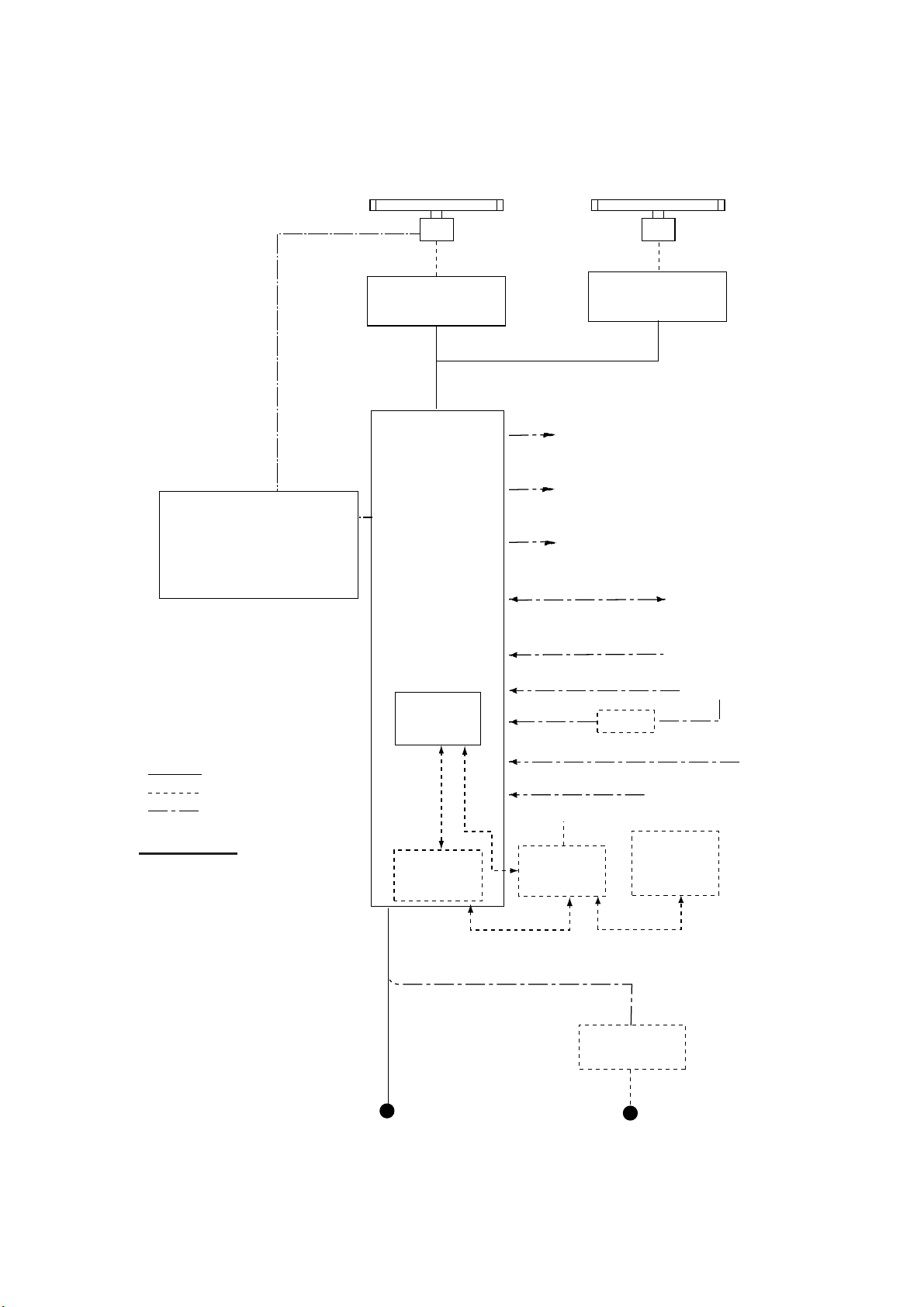
SYSTEM CONFIGURATION
Blackbox type
POWER SUPPLY UNIT
PSU-007
For FAR-2137S-BB
FAR-2137S-BB
ANTENNA UNIT
(Performance Monitor PM-51 built in
(FAR-2137S-BB)
PROCESSOR UNIT
RPU-013
FAR-2117-BB/2127-BB
ANTENNA UNIT
(Performance Monitor PM-31 built in
(FAR-2117-BB, FAR-2127-BB)
VGA Monitor
CONTROL UNIT
RCU-014
(Keyboard)
or
RCU-015
(Trackball)
Control Unit
RCU-016
(Remote)
Sub Display
: Standard
: Option
: Dockyard supply
Category of Units
Antenna unit: Exposed to weather
All other units: Protected from weather
Alarm
VDR
External Monitor
IEC-61162-1 Serial Data
(Input/Output)
IEC-61162-1 Serial Data
(Input)
AD-100
Memory Card
Interface Unit
CU-200
HUB has ports for connection of up to 7 processor units
DC spec
Rectifier
RU-3424
RU-1746B-2
Transformer Unit
RU-1803
Navigator (INS, GPS, etc.)
Speed Log
Gyrocompass
Track Control Unit
OR
Memory Card
Interface Unit
CU-200 x 2
AC spec
AIS
100-230 VAC
Switching Hub
HUB-100
xvi
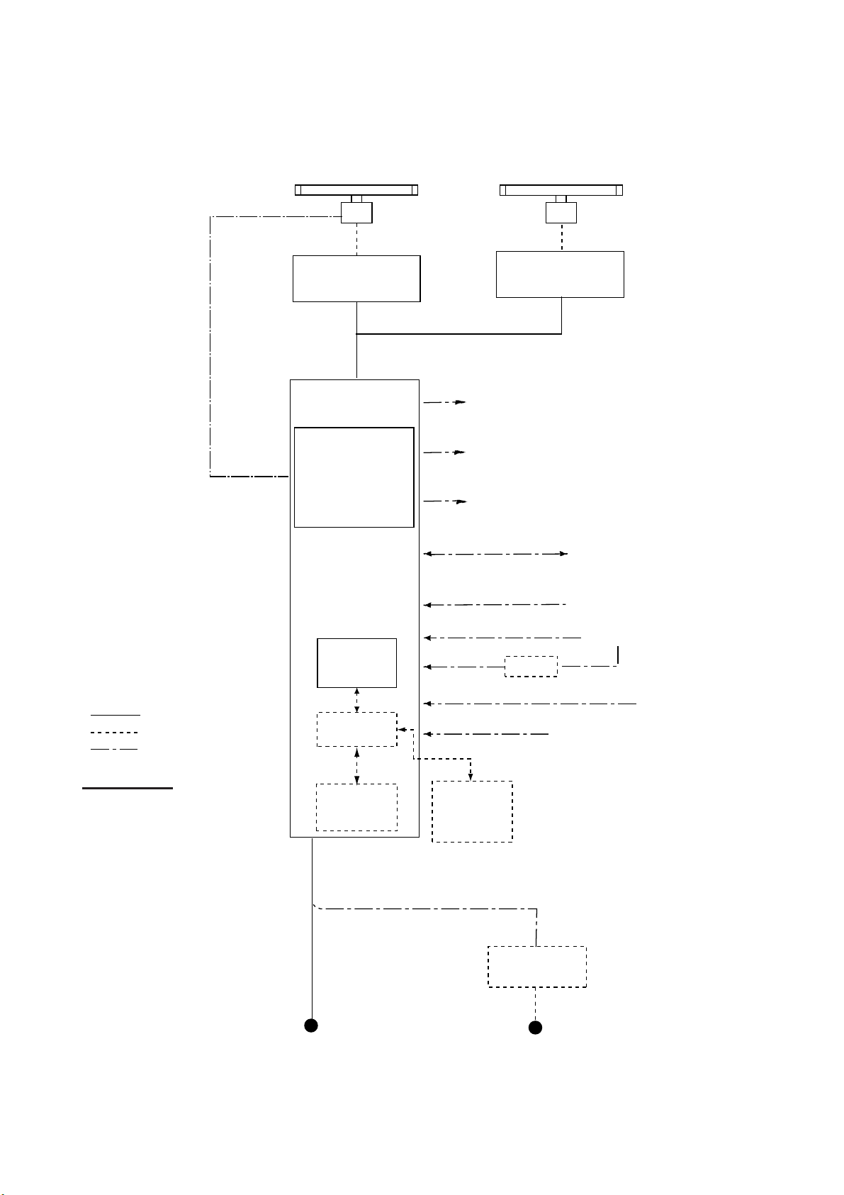
Page 19
Console type RCN-001/RCN-002
FAR-2137S(-D)/2837S(-D)/2837SW(-D)
ANTENNA UNIT
(Performance Monitor PM-51 built in)
SYSTEM CONFIGURATION
FAR-2117(-D)/2127(-D)/
2817(-D)/2827(-D)/2827W(-D)
ANTENNA UNIT
(Performance Monitor PM-31 built in)
POWER SUPPLY UNIT
PSU-007
(-D)
/2837S
For FAR-2137S
OR
POWER SUPPLY UNIT
PSU-011*
(For FAR-2827W(-D)/2837SW(-D)
* Russian flag only
(-D)
Waveguide or
Coax cable
(For FAR-2837SW(-D))
TRANSCEIVER UNIT
RTR-082
For FAR-2837SW
CONSOLE
RCN-001/002
(-D)
TRANSCEIVER UNIT
RTR-081
For FAR-2827W(-D)
Alarm
VDR
External Monitor
IEC-61162-1 Serial Data
(Input/Output)
IEC-61162-1 Serial Data
(Input)
Waveguide
(For FAR-2827W(-D))
Navigator (INS, GPS, etc.)
Speed Log
: Standard
: Option
: Dockyard supply
Category of Units
Antenna unit: Exposed to weather
All other units: Protected from weather
PROCESSOR
May also
be installed
externally.
Memory Card
Interface Unit
100-115 VAC/
220-230 VAC
1φ, 50/60 Hz
UNIT
RPU-013
OR
CU-200
100-230 VAC
Switching Hub
HUB-100
Gyrocompass
AD-100
AIS
Track Control Unit
Memory Card
Interface Unit
CU-200
(Max. 2 total)
AC spec
Transformer Unit
RU-1803
440 VAC
1φ, 50/60 Hz
xvii
Page 20
SYSTEM CONFIGURATION
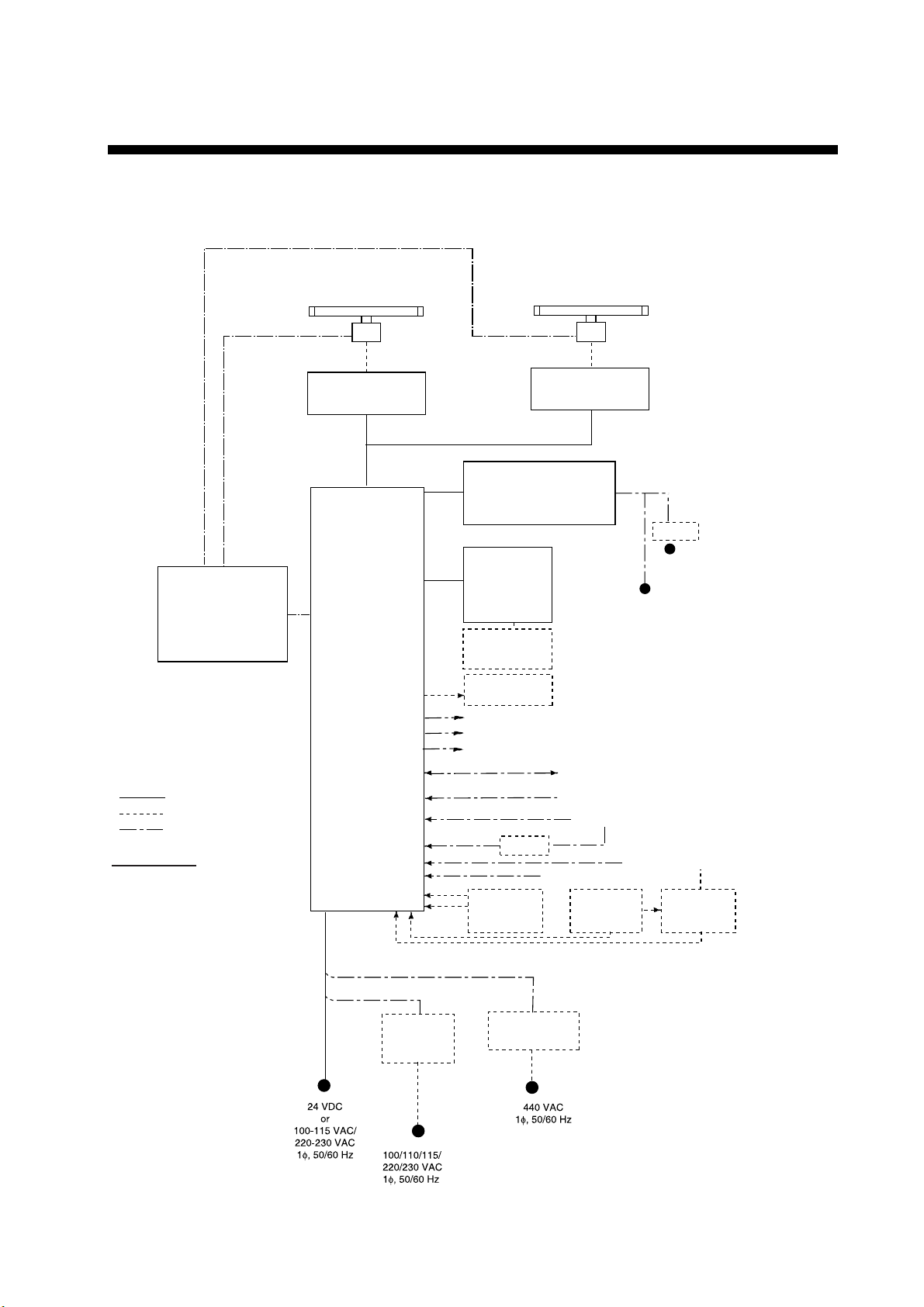
Console type RCN-003/RCN-004
FAR-2137S(-D)/2837S(-D)/2837SW(-D)
(Performance Monitor PM-51 built in)
ANTENNA UNIT
Waveguide or Coax cable
(For FAR-2837SW(-D))
TRANSCEIVER UNIT
RTR-082
For FAR-2837SW(-D)
CONSOLE
RCN-003/004
POWER SUPPLY UNIT
PSU-007
(For FAR-2137S(-D)/2837S(-D))
(For FAR-2827W
* Russian flag only
OR
POWER SUPPLY UNIT
PSU-011*
(-D)
/2837SW
(-D)
)
FAR-2117(-BB,-D)/2127(-D)/2817(-D)/
(Performance Monitor PM-31 built in)
TRANSCEIVER UNIT
For FAR-2827W(-D)
Alarm
VDR
External Monitor
IEC-61162-1 Serial Data
(Input/Output)
2827(-D)/2827W(-D)
ANTENNA UNIT
Waveguide
(For FAR-2827W(-D))
RTR-081
Navigator (INS, GPS, etc.)
: Standard
: Option
: Dockyard supply
Category of Units
Antenna unit: Exposed to weather
All other units: Protected from weather
PROCESSOR
UNIT
RPU-013
Switching Hub
HUB-100
Memory Card
Interface Unit
CU-200
IEC-61162-1 Serial Data
(Input)
AD-100
Memory Card
Interface Unit
CU-200
(Max. 2 total)
AC spec
Transformer Unit
RU-1803
Speed Log
Gyrocompass
AIS
Track Control Unit
xviii
100-115 VAC/
220-230 VAC
1φ, 50/60 Hz
440 VAC
1φ, 50/60 Hz
Page 21

Antenna unit
SYSTEM CONFIGURATION
FAR-2117(-BB,-D)
FAR-2127(-BB,-D)
FAR-2827(-D)
FAR-2137S(-BB,-D) RSB-098/099 (21/26 rpm, 200 VAC, 3ø, 50 Hz; 220 VAC, 3ø, 60 Hz;
FAR-2157(-BB,-D) RSB-106 (18/22 rpm, 200 VAC, 3ø, 50Hz, 220 VAC, 3ø, 60 Hz)
FAR-2167DS(-BB,-D) RSB-111 (21/26 rpm, 200 VAC, 3ø, 50Hz, 220 VAC, 3ø, 60Hz)
FAR-2827W(-D) RSB-103 (24 rpm, powered by processor unit)
FAR-2837S(-D) Same as FAR-2137S
FAR-2837SW(-D) RSB-104/105 (21/26 rpm, 200 VAC, 3ø, 50 Hz; 220 VAC, 3ø, 60 Hz;
RSB-096 (24 rpm)
RSB-097 (42 rpm)
380 VAC, 3ø, 50 Hz, 440 VAC, 3ø, 60 Hz)
RSB-100/101/102 (45 rpm, 220 VAC, 3ø, 50/60 Hz(HSC);
440 VAC, 3ø, /60 Hz(HSC))
RSB-107 (22 rpm, 24 VDC)
RSB-112 (21/26 rpm, 380 VAC, 3ø, 50Hz, 440 VAC, 3ø, 60Hz)
380 VAC, 3ø, 50 Hz, 440 VAC, 3ø, 60 Hz)
Radiator
FAR-2117(-BB,-D), FAR-2127(-BB,-D), FAR-2827(-D) XN12AF , XN20AF, XN24AF
FAR-2137S(-BB,-D) SN30AF, SN36AF
FAR-2157(-BB,-D) XN4A, XN5A
FAR-2167DS(-BB,-D) SN30AF, SN36AF
FAR-2827W(-D) XN20AF, XN24AF
FAR-2837S(-D) SN30AF, SN36AF
FAR-2837SW(-D) SN30AF, SN36AF
xix
Page 22

SYSTEM CONFIGURATION
This page intentionally left blank.
xx
Page 23
FURUNO
SPECIFICATIONS OF MARINE RADAR/ARPA
FAR-2157/2167DS
1 ANTENNA RADIATOR
1.1 Type Slotted waveguide array
1.2 Beam width and sidelobe attenuation
Radiator type
Length 8 ft 10 ft 9.5 ft 12 ft
Beam width(H) 0.75° 0.75° 2.3° 1.8°
Beam width(V) 20° 25°
Sidelobe within ±10° -28 dB -26 dB -24 dB
Sidelobe outside ±10°
Applicable type
1.3 Polarization Horizontal
1.4 Rotation
FAR-2157 RSB-106: 18 rpm (50 Hz)/22 rpm (60 Hz), RSB-107: 22 rpm
FAR-2167DS 21 rpm (50 Hz), 26 rpm (60 Hz)
1.5 Wind tolerance Relative wind 100 kn
1.6 De-icer (option) On: When temperature goes down to +5°C
Off: When temperature goes up to +12°C
X-band S-band
XN4A XN5A
SN30AF SN36AF
-32 dB -30 dB -30 dB
FAR-2157 FAR-2167DS
FAR-2157/2167DS
2 RF TRANSCEIVER
2.1 Frequency
X-band 9410 MHz ±30 MHz
S-band 3050 MHz ±30 MHz
2.2 Output power
FAR-2157 50 kW
FAR-2167DS 60 kW
2.3 Range, pulse repetition frequency (PRF), pulselength
PRF (Hz)
1900 (SP)
1100 (MP)
600 (LP)
600 (LP)
2nd traced echo reduce mode (w/o short pulse): 500 Hz approx.
0.125 0.25 0.5 0.75 1 1.5 2 3 4 6 8 12 16 24 32 48 72 96 120
0.08 µs
0.2 µs
Range (NM)
0.6 µs
2.4 Duplexer Ferrite circulator with diode limiter
3 MONITOR UNIT
1.2 µs
3.1 Screen Raster scan, daylight bright, yellow or green echoes in 32 levels
3.2 Scanning Non-Interlace at 64 kHz horizontal, 60 Hz vertical
3.3 Display
Size 20.1-inch color LCD
Display area 399 x 319 mm
SP - 1 E3522S01A-M
Page 24

FURUNO
FAR-2157/2167DS
Resolution 1280 x 1024 pixel
Effective radar diameter 308 mm (H: 64 kHz, V: 60 Hz)
Viewable range 1080 mm
3.4 Minimum range 22 m
3.5 Range discrimination 26 m
3.6 Range scales, Ring interval, Number of rings
Range (NM) 0.125 0.25 0.5 0.75 1 1.5 2 3 4 6 8 12
Ring interval (NM) 0.025 0.05 0.1 0.25 0.25 0.25 0.5 0.5 1 1 2 2
Number of rings 5 5 5 3 6 6 4 6 4 6 4 6
16 24 32 48 72 96 120
4 4 8 8 12 16 20
4 6 4 6 6 6 6
3.7 Range accuracy 1% of the maximum range of the scale in use or 10m,
whichever is the greater
3.8 Bearing discrimination 1.18° (XN4A), 0.98° (XN5A), 2.5° (SN30AF), 2.0° (SN36AF)
3.9 Bearing accuracy ±1°
3.10 Presentation mode Head-up, Cursor-gyro, Course-up, North-up,
True motion (sea or ground stabilization)
3.11 ARPA Auto or manual acquisition: 100 targets in 0.2-24(32) NM
Auto tracking on all acquired targets
Tracking: 5/10 pts on all target
3.12 AIS Capacity: 1000 targets, Tracking: 10 pts on all target
Time of vector: Off/30s/1-60 minutes
3.13 Radar map 20,000 pts in radar mode, 6000 pts on IC card in chart mode
3.14 Acquisition zone 2 zones
3.15 Interswitch function Selectable from menu
4 INTERFACE
4.1 Heading signal Synchro signal (20-100VDC or 20-135VAC 50/60/400/500Hz) or
Stepper signal (20-100VDC), built-in interface (option) required,
AD-10 format or IEC61162-2
4.2 Speed log IEC61162-1
4.3 AIS IEC61162-2
4.4 Input data sentences ABK, ACK, ALR, BWC, BWR, DBK, DBS, DBT, DPT, DTM, GGA,
GLL, HDT, MTW, MWV, RMB, RMC, RTE, THS, VBW, VDM, VDO,
VDR, VHW, VTG, VWR, VWT, WPL, ZDA
4.5 Output data sentences ABM, ACK, ALR, BBM, OSD, RSD, TLB, TLL, TTD, TTM, VSD
5 POWER SOURCE
5.1 Monitor unit 24 VDC:2.3 A or 100-230 VAC: 0.7 A, 1 phase, 50/60 Hz
5.2 Processor unit 24VDC or 100-115/220-230 VAC: 3.0/1.5A, 1 phase, 50/60 Hz
5.3 Power supply unit
FAR-2157 main 100-115/220-230 VAC: 4.4/2.0A, 1 phase, 50/60 Hz
FAR-2157 motor 24VDC: 4A or 200/220 VAC: 2.0A, 3 phase, 50/60 Hz
SP - 2 E3522S01A-M
Page 25

FURUNO
FAR-2167DS 220/380VAC: 3/1.5A, 3 phase, 50 Hz or
220/440VAC: 3/1.5A, 3 phase, 60 Hz
5.4
Antenna unit 200/220/380/440 VAC, 3 phase, 50/60 Hz
Antenna voltage input (100 kn)
Model
FAR-2167DS 3.0 A 1.5 A
200 VAC, 3 φ 50 Hz,
220 VAC, 3 φ, 60 Hz
5.5 Console 115/230 VAC, 1 phase, 50/60 Hz
5.6
Transformer (option)
For single phase RU-1803:
440 VAC, 1 phase, 50/60 Hz
For triple phase RU-5693: 110 VAC, 3 phase, 60 Hz
RU-6522: 220 VAC, 3 phase, 50 Hz
RU-5466-1: 440 VAC, 3 phase, 50 Hz
6 ENVIRONMENTAL CONDITIONS
6.1 Ambient temperature
Monitor/processor/transceiver/control/power supply unit
-15°C to +55°C
Antenna unit -25°C to +55°C (storage +70°C)
6.2 Relative humidity 95% max. at 40°C
6.3 Degree of protection
Monitor/processor/control/power supply unit IPX0
Antenna unit IPX6
6.4 Vibration IEC60945 Ed.4
FAR-2157/2167DS
380 VAC, 3 φ, 50 Hz,
440 VAC, 3 φ, 60 Hz
7 COLOR
7.1 Monitor unit Chassis: 2.5GY5/1.5, Panel: N3.0 (fixed)
7.2 Processor/power supply unit 2.5GY5/1.5
7.3 Control unit N3.0 (fixed)
7.4 Antenna unit N9.5 (fixed)
8 PERFORMANCE MONITOR (PM-50)
8.1 PM-30 (X-band)
8.1.1 Frequency range 9370 to 9450 MHz
8.1.2 Input power +8dBm min, +28dBm max.
8.1.3 Output power -36dBm (2
8.1.4 Step levels 7.5 to 10.5 dB (1
nd
pulse max. output), -56dBm (2nd pulse min. output)
st
pulse to 2nd pulse)
8.2 PM-50 (S-band)
8.2.1 Frequency range 3020 to 3080 MHz
8.2.2 Input power -5dBm min, +15dBm max.
8.2.3 Output power -15dBm (2
8.2.4 Step levels 9.0 to 11.0 dB (1
nd
pulse max. output), -35dBm (2nd pulse min. output)
st
pulse to 2nd pulse)
9 SWITCHING HUB (HUB-100)
9.1 Access format CSMA/CD
9.2 Switching format Store and forward
SP - 3 E3522S01A-M
Page 26

FURUNO
FAR-2157/2167DS
9.3 Transmission speed Semi-duplex: 10 Mbps/100 Mbps, Full-duplex: 20 Mbps/200 Mbps
9.4 Cable category 10 BASE-T: Category 3 or higher STP cable
100 BASE-TX: Category 5 or higher STP cable
9.5 Maximum cable length 100 m
9.6 Number of ports 8 ports
9.7 Port functions Auto-MDI/MDI-X compliant (straight/cross cable auto-recognition)
EMC compliant (STP cable port)
3 LED injectors (Link/Act, Full-duplex/Collision, 100/10 Mbps)
9.8 Environmental conditions
Ambient temperature -15 to +50°C
Relative humidity 95% (at 40°C)
EMC IEC 60945
Degree of protection IPX0
9.9 Power source 100-230VAC: 0.1A or less
9.10 Color N3.0
SP - 4 E3522S01A-M
Page 27

1. RADAR OPERATION
1.1 Turning on the Power
The [POWER] switch ( ) is located at the left corner of the control unit. Open the
POWER switch cover and press the switch to turn on the radar system. To turn
off the radar, press the switch again. The screen shows the bearing scale and
digital timer approximately 30 seconds after power-on. The
three minutes of warm-up time. During this period the magnetron (transmitter
tube) is warmed for transmission. When the timer has reached 0:00, the
indication “ST-BY” appears at the screen center, meaning the radar is now ready
to transmit pulses.
In the stand-by condition, markers, rings, map, charts, etc. are not shown.
Further, ARP is cancelled and the AIS display is erased.
In warm-up and stand-by condition, ON TIME and TX TIME counts in hours and
tenths of hour appear at the screen center.
Note: Avoid turning the power on directly after it has been turned off. Wait
several seconds before reapplying the power, to ensure proper start up.
timer counts down
1.2 Transmitter ON
After the power is turned on and the magnetron has warmed up, ST-BY appears
at the screen center, meaning the radar is ready to transmit radar pulses. You
may transmit by pressing the [STBY/TX] key on the full keyboard or roll the
trackball to choose the TX STBY box at the bottom left corner of the display and
then push the left button (above the trackball). The label at the left-hand side of
the guidance box at the bottom right corner of the screen changes from TX to
STBY.
TX
STBY
TX STBY box
STBY
/
Radar display
Guidance
box
1-1
Page 28
1. RADAR OPERATION
The radar is initially set to previously used range and pulse length. Other
settings such as brilliance levels, VRMs, EBLs and menu option selections are
also set to previous settings.
The [STBY/TX] key (or TX STBY box) toggles the radar between STBY and
TRANSMIT status. The antenna stops in stand-by and rotates in transmit. The
magnetron ages with time resulting in a reduction of output power. Therefore, it
is highly recommended that the radar be set to stand-by when not used for an
extended period of time.
Quick start
Provided that the radar was once in use with the transmitter tube (magnetron)
still warm, you can turn the radar into TRANSMIT condition without three
minutes of warm-up. If the [POWER] switch has been turned off by mistake or
the like and you wish to restart the radar promptly, turn on the [POWER] switch
not later than 10 seconds after power-off.
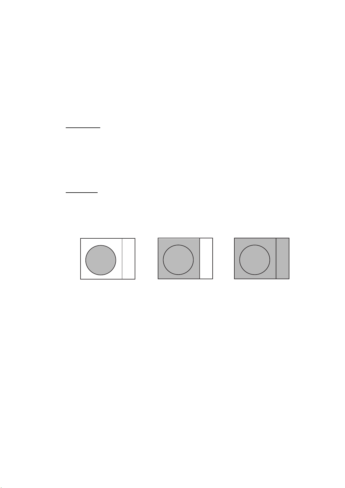
Echo area
The echo display area for the non-IMO radar (B, C and W types) is available in
three configurations: round, wide, and full screen. You can select configuration
with 7 ECHO AREA on the ECHO menu.
Round Wide Full
1-2
Page 29
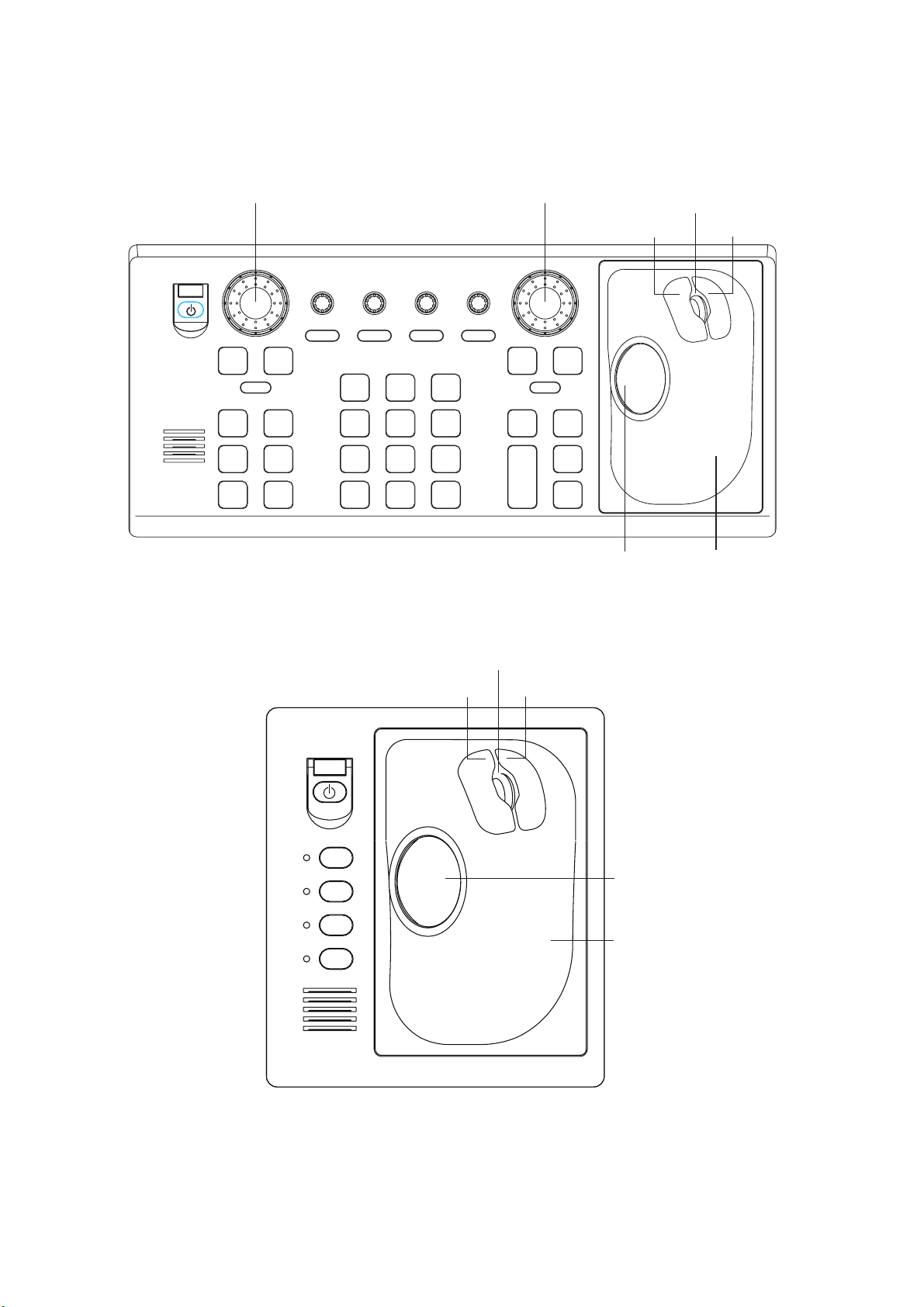
1.3 Control Unit
Two types of control units are available: Control Unit RCU-014 (full keyboard)
and Control Unit RCU-105 (palm control).
EBL rotary control VRM rotary control
1. RADAR OPERATION
Wheel
Left button Right button
OFF
EBL
F1
F3 F4
ALARM
ACK
ON
F2
STBY
TX
BRILL
HL
OFF
45
OFF
CENTER
78
VECTOR
TIME
CANCEL
TRAILS
21
EBL
OFFSET
CU/TM
RESET
VECTOR
MODE
0
BRILL
A/C SEAA/C RAIN
3
MODE
6
INDEX
LINE
9
TARGET
LIST
ENTER
MARK
GAIN
OFF
MENU
+
RANGE
ON
VRM
ACQ
TARGET
DATA
TARGET
-
CANCEL
Trackball
Control Unit RCU-014 (full keyboard)
Wheel
Left button Right button
Trackball
Module
F1
Trackball
F2
F3
Trackball
F4
Module
Control Unit RCU-015 (palm control)
1-3
Page 30

1. RADAR OPERATION
Control description
Control Description
Control Unit RCU-014 (full keyboard)
POWER Turns the system on and off.
EBL and VRM rotary controls Adjust EBL and VRM, respectively.
EBL ON, EBL OFF Turns the EBLs on and off, respectively.
F1-F4 Execute menu short cut assigned.
ALARM ACK Silences audible alarm.
STBY TX Toggles between stand-by and transmit.
BRILL Adjusts display brilliance.
A/C RAIN Suppresses rain clutter.
A/C SEA Suppresses sea clutter.
GAIN Adjusts sensitivity of the radar receiver.
HL OFF Temporarily erases the heading line while pressed.
EBL OFFSET
MODE Chooses presentation mode.
OFF CENTER Shifts own ship position.
CU/TM RESET • Moves own ship position in 75% radius in stern direction.
INDEX LINE Turns index lines on and off.
VECTOR TIME Chooses vector time (length).
VECTOR MODE Chooses vector mode, relative or true.
TARGET LIST Displays ARP target list.
CANCEL TRAILS Cancels all target trails. In menu operation it clears line of data.
ENTER MARK Enters marks; terminates keyboard input.
VRM ON, VRM OFF Turns the VRMs on and off, respectively
MENU Opens and closes the MAIN menu; closes other menus.
ACQ
RANGE Chooses radar range.
TARGET DATA
TARGET CANCEL
Control Unit RCU-015 (palm control)
POWER Turns the system on and off.
F1-F4 Execute menu short cut assigned.
Enables, disables the EBL offset. In menu operation, switches
polarity from North to South and East to West and vice versa.
• Resets the heading line to 0° in course-up and true motion
modes.
• Acquires a target for ARP after choosing it with the trackball.
• Changes a sleeping AIS target to an activated one after
choosing it with the trackball.
Displays target data for ARP or AIS target chosen with the
trackball.
Cancels tracking on ARP, AIS or reference target chosen with
the trackball.
1-4
Page 31

1.4 Main Menu
You may access the MAIN menu from the full keyboard or by using the trackball.
In later sections only the procedure for menu operation by trackball is given.
Main menu operation by keyboard
1. Press the [MENU] key. The MAIN menu appears in the text area at the right
side of the screen.
[MAIN MENU]
1 [ECHO]
2 [MARK]
3 [ALARM]
4 [ARP
5 [PLOTTER]
6 [CARD]
7 [NAV DATA]
8 [NAV LINE
9 [CUSTOMIZE
AIS]
WPT]
TEST]
1. RADAR OPERATION
Echo processing functions
Mainly turns markers on/off.
Sets guard alarm functions; outputs alarm signal.
Sets ARP
Chart and track functions
Memory card functions
Turns nav data on/off.
Processes nav lines and waypoints.
Customizes operation; executes diagnostics.
and AIS functions.
2. Press the numeral key corresponding to the menu you wish to open. For
example, press the [2] key to open the MARK menu.
[MARK]
1 BACK
2 OWN SHIP MARK
OFF/ON
3 STERN MARK
OFF/ON
4 INDEX LINE BEARING*
1
REL/TRUE
2
5 INDEX LINE*
1/2/3/6
6 INDEX LINE MODE*
3
VERTICAL/HORIZONTAL
7 [BARGE MARK]
8 EBL OFFSET BASE
STAB GND/STAB HDG/
STAB NORTH
9 [EBL, VRM, CURSOR SET]*
0 RING
OFF/ON
3. Press the numeral key corresponding to the
item you wish to set.
4. Consecutively press the same numeral key
pressed at step 3 to choose appropriate
option and then press the [ENTER MARK]
key to register your selection.
5. Press the [MENU] key to close the menu.
MAIN menu
*1W-type shows INDEX LINE1. Same choices as INDEX LINE.
2
*
W-type shows INDEX LINE2. Same choices as INDEX LINE.
3
*
Shown when INDEX LINE is set to other than "1" .
Not shown on IMO or A type.
4
*
IMO and A types show
9 EBL CURSOR BEARING (REL/TRUE)
4
MARK menu
Useful keys in menu operation
To clear a line of numeric data:
Use the [CANCEL TRAILS] key.
Switch between plus and minus,
North and South or East and West:
Use the [2] key.
1-5
Page 32

1. RADAR OPERATION
Main menu operation by trackball
1. Roll the trackball to choose the MENU box at the right side of the screen. The
guidance box at the bottom right corner (see the illustration at the bottom of
the next page for location) now reads “DISP MAIN MENU.”
2. Push the left button to display the MAIN menu.
[MAIN MENU]
1 [ECHO]
2 [MARK]
3 [ALARM]
4 [ARP
5 [PLOTTER]
6 [CARD]
7 [NAV DATA]
8 [NAV LINE
9 [CUSTOMIZE
l
AIS]
WPT]
3. Roll the wheel or trackball to choose the menu you wish to open and then
push the wheel or the left button. For example, choose the 2 [MARK] menu
and then push the wheel or the left button.
[MARK]
1 BACK
2 OWN SHIP MARK
OFF/ON
3 STERN MARK
OFF/ON
4 INDEX LINE BEARING*
REL/TRUE
2
5 INDEX LINE*
1/2/3/6
6 INDEX LINE MODE*
VERTICAL/HORIZONTAL
7 [BARGE MARK]
8 EBL OFFSET BASE
STAB GND/STAB HDG/
STAB NORTH
9 [EBL, VRM, CURSOR SET]*
0 RING
OFF/ON
1
3
MENU
Menu box
Echo processing functions
Mainly turns markers on/off.
Sets guard alarm functions; outputs alarm signal.
Sets ARP
Chart and track functions
Memory card functions
Turns nav data on/off.
TEST]
Processes nav lines and waypoints.
Customizes operation; executes diagnostics.
MAIN menu
*1W-type shows INDEX LINE1. Same choices as INDEX LINE.
2
*
W-type shows INDEX LINE2. Same choices as INDEX LINE.
3
*
Shown when INDEX LINE is set to other than "1" .
Not shown on IMO or A type.
4
*
IMO and A types show
9 EBL CURSOR BEARING (REL/TRUE)
4
and AIS functions.
1-6
MARK menu
4. Roll the wheel to choose item desired and then push the wheel or the left
button.
5. Roll the wheel to choose option desired and then push the wheel or the left
button to register your selection.
6. Push the right button to close the menu. (Several pushes may be necessary
depending on the menu used.)
Page 33

1. RADAR OPERATION
1.5 Operation Using the On-Screen Boxes
All radar functions can be accessed by using the trackball alone. This is done by
choosing the appropriate on-screen box with the trackball and operating the
trackball module to choose item and option. (See paragraph 1.9 for location of all
on-screen boxes.) On-screen boxes come in two varieties: Function selection
and function selection w/pop-up menu. On-screen boxes of the latter type have
“►” at the right side of their boxes, as in the MARK box shown below.
To operate the radar using on-screen boxes, do the following:
1. Roll the trackball to place the trackball marker inside the box desired.
Note: The trackball marker changes its configuration according to its location.
It is an arrow when placed outside the effective display and a cursor
(+) when inside the effective display. See the illustration on the next
page for further details.
For example, choose the MARK box, which is at the bottom left corner.
MARK
Mark type last
selected, mark
number
Bearing and range from
own ship to mark
162.5
1
-> +
°
T 11.7 NM
MARK box
When a box is correctly selected, its color changes from green to yellow
(default colors) and the guidance box at the bottom right corner shows
operational guidance. The operational guidance shows the function of the
left and right buttons, with a diagonal line separating the information. For the
MARK box, for example, the operational guidance is “MARK SELECT /
MARK MENU.” In this case you would push the left button to choose a mark
or push the right button to open the MARK menu.
Function of left button
Function of right button
MARK Box
MARK
1
> +
Arrow
For choosing
on-screen box
MARK
SELECT
MARK
/
MENU
Guidance box
Guidance box (Example: guidance for MARK box)
1-7
Page 34

1. RADAR OPERATION
Trackball marker location and guidance box indication
The trackball marker is either a cursor (+) or an arrow ( ) depending
on whether it is within or outside the display area, respectively.
Further, the indication in the guidance box changes according to
trackball marker location.
Trackball marker is out of
effective display area
(incl. text area) and
not selecting a box:
The trackball marker is
an arrow
Guidance box reads
"JUMP CURSOR / DISP MENU."
Push the left button to choose the on-screen
box closest to the arrow or push the right
button to display the MAIN menu.
To choose boxes successively, push the wheel
when the guidance box reads as above.
Then, the nearest box is selected and marked
with the double-ended arrow ( ) and the
guidance box reads
"JUMP FORWARD / JUMP BACKWARD."
Hit the left button to go to the box below or
adjacent to the currently selected box or hit
the right button to go to the box above or
adjacent to the currently selected box.
Continue pushing a button to choose boxes
successively. This is convenient for operation
under heavy pitching and rolling. To cancel this
feature, push the wheel when the guidance box
reads as above.
Guidance box reads
"TARGET DATA & ACQ / CURSOR MENU."
In this condition you may access cursor-operated
+
Trackball marker is within
effective display area:
The trackball marker is
a cursor
functions, by hitting the left button for direct
selection of function or the right button to choose
desired functions from the CURSOR menu. For
further details about the CURSOR menu,
see paragraph 1.6.
2. Push the left button (or roll the wheel depending on the box) until the desired
option is displayed in the box.
Note: When you chose an on-screen box’s option by rolling the wheel, the
box and its contents turn red. This simply indicates that the chosen
setting is different from the currently active setting. To change the
setting, push the wheel or the left button. If neither the wheel nor the
left button is pushed within about 30 seconds after operating the wheel,
the previous setting is automatically restored.
1-8
Page 35

1. RADAR OPERATION
3. The pop-up menu attached to the MARK box is the MARK menu. To open the
menu, push the right button. The menu opens in the text area at the right side
of the screen.
[MARK MENU]
1 ORIGIN MARK STAB
GND/SEA
2 MARK KIND
ORIGIN MARK(No. )/
ORIGIN MARK(SYM)/
MAP MARK/
WP 1~50/
WP 51~ 100/
WP 101~150/
WP 151~ 200/
OWN SHIP SHAPE
8 MARK POSN
CURSOR/OS/L/L
°000.00 N
00
000
°000.00 E
9 MAP DISPLAY
OFF/ON
0 MAP MARK COLOR*
RED/GRN/BLU/YEL/
CYA/MAG/WHT
* Not available on IMO
or A type
MARK menu
Note: Any menu may be operated from the full keyboard or the trackball, or a
combination of the two in case of Control Unit RCU-014. Note that in
later sections only the procedure for menu operation by the
trackball is given.
4. Roll the wheel to choose item desired and then push the wheel or the left
button. Selected item is initially shown in reverse video and changes to
normal video and circumscribed when the wheel or the left button is pushed.
5. Roll the wheel to choose option desired and then push the wheel or the left
button. Selected option is initially shown in reverse video and changes to
normal video and circumscribed when the wheel or the left button is pushed.
6. Push the right button to close the menu. (On some menus several presses of
the right button are required to close the menu.)
1-9
Page 36

1. RADAR OPERATION
1.6 Cursor Menu
Functions which require the use of the cursor, such
[CURSOR MENU]
as EBL offset and zoom, may be activated directly
2
from the guidance box or from the CURSOR menu,
either method with the cursor inside the effective
display area. Below is the procedure for choosing a
cursor-related function from the CURSOR menu. In
later sections only the procedure for selection from
the guidance box is given.
1. Roll the trackball to place the cursor inside the
effective display area.
2. Roll the wheel to show “TARGET DATA & ACQ /
CURSOR MENU” in the guidance box.
3. Push the right button to show the CURSOR
menu.
↓
TARGET DATA & ACQ/
TARGET CANCEL/
ARP TGT DATA & ACQ/
TARGET TRACK ON*/
TARGET TRACK OFF*/
REF MARK/
EBL OFFSET/
OFFCENTER/
ZOOM/
MARK DELETE/
OWN TRACK DELETE/
TGT TRACK DELETE/
CHART ALIGN/
8
↑
*
Not available on IMO type
4. Roll the wheel to choose “2” and then push the
wheel or the left button.
5. Roll the wheel to choose function desired and then push the wheel or the left
button.
Note: For operation from the keyboard, you may press the [2] key to choose a
function in top-to-bottom order or the [8] key to choose in reverse order.
Cursor Menu item Description
TARGET DATA & ACQ ARP: Acquires ARP target; displays data for chosen ARP target.
AIS: Activates sleeping AIS target; display data for chosen AIS
target.
TARGET CANCEL ARP: Cancels tracking on chosen ARP target.
AIS: Sleeps chosen AIS target.
ARP TGT DATA & ACQ Acquires chosen echo as ARP target.
TARGET TRACK ON Turns ARP target track on. (A, B, C and W types)
TARGET TRACK OFF Turns ARP target track off. (A, B, C and W types)
REF MARK Inscribes reference mark, for target-based speed input.
EBL OFFSET Offsets EBL to measure range and bearing between two targets.
OFF CENTER Shifts screen center to chosen location.
ZOOM Zooms chosen location.
MARK DELETE Deletes chosen mark (plotter mark, origin mark or waypoint
mark).
OWN TRACK DELETE Deletes own ship’s tracks.
TGT TRACK DELETE Deletes other ship’s tracks.
CHART ALIGN Aligns chart with radar picture.
1-10
Page 37

6. The guidance box shows “XX / EXIT.” (XX = function chosen). Roll the
trackball to place the cursor where desired.
7. Push the left button to execute the function selected at step 5.
8. To quit the function selected, push the right button when the guidance box
shows “XX / EXIT.” (XX = function chosen at step 5)
1.7 Monitor Brilliance
The brilliance of the entire screen should be adjusted according to lighting
conditions. Monitor brilliance should be adjusted before adjusting relative
brilliance levels on the BRILL menu to be explained later.
Note: The brilliance of a commercial monitor cannot be adjusted from the radar.
See the owner’s manual of the commercial monitor for how to adjust its
brilliance.
By keyboard
1. RADAR OPERATION
Operate the [BRILL] control on the control unit to adjust brilliance. Turn it
clockwise to increase brilliance; counterclockwise to decrease brilliance. Watch
the BRILL box (see illustration below) to know current brilliance level.
By trackball
1. Roll the trackball to place the arrow on the brilliance level indicator in the
brilliance level indication box at the bottom left corner of the screen.
Brilliance bar
Shows brilliance level.
Place arrow inside box
to adjust screen brilliance.
BRILL1
Brillance, color set no.
(For details, see para. 1.50.)
26
Brilliance level
Brilliance level indicator
2. Roll the wheel downward to increase brilliance or roll it upward to decrease
brilliance. The length of the brilliance bar increases or decreases with
operation of the wheel.
Note: If nothing appears on the screen at power-up when using Control Unit
RCU-015 (palm control) or when the radar is in stand-by, press and hold
down any key except the power switch for four seconds to automatically
set up for medium display brilliance.
1-11
Page 38

1. RADAR OPERATION
1.8 Choosing the Display Mode
This radar has the following display modes:
• IMO, A type: Radar, Radar + Plotter
• B, C, W type: Radar, Radar + Plotter, Plotter
Choose a display mode as below. Note that a display mode cannot be chosen
when the menu is open.
1. Roll the trackball to place the arrow in the DISPLAY MODE box at the top of
the screen.
DISPLAY
XX*
DISPLAY MODE box
2. Push the left button to choose appropriate mode:
RADAR: Radar picture
* XX = display mode
+PLOTTER: Radar picture + plotter picture (incl. chart)
PLOTTER: Plotter picture
1-12
Page 39

1.9 On-Screen Boxes and Markers
Reference Point Box
Trial Maneuver (Elapsed time shown
when trial maneuver is active.)
PICTURE Box, Main Picture Settings
PULSELENGTH Box
ANTENNA Box
PRESENTATION MODE Box
RANGE Box
DISPLAY MODE Box
Heading Marker
6
HEAD UP TB RM
ANT 1 X-BAND
PULSE S1
PICTURE4
IR OFF
ES OFF
EAV OFF
AUTO RAIN
OFF
NM/1DISPLAY
RADAR
320
310
300
Index
330
340
Heading
Line
350
000
Line
290
280
Guard
Zone
Cursor
No. 1
270
EBL
260
250
No. 2
EBL
OS
Symbol
No. 1
220
WATCH
11 : 28
VRM
210
200
Stern
Marker
190
Origin Mark
180
IL1
ON
032. 0°T
5. 60NM
MARK
190.0°T, 5.75NM
BRILL1
HL
EBL1
OFF
TX
EBL2
STBY
240
230
+
26
>280.9°T<
240. 8°R
WATCH Box
EBL2 Box
EBL1 Box
(Alarm watch
time)
TX/STBY Box
HL OFF Box
BRILL Box
MARK Box
Bearing and range to mark
IL (Index Line) Box
Index line orientation,
Index line interval
010
North
Marker
170
SET and DRIFT Boxes
CURSOR DATA Box
GAIN Setting
A/C SEA Setting
A/C RAIN Setting
TUNING Setting
040
140
GAIN
SEA AUTO
RAIN
TUNE AUTO
050
130
VRM1
VRM2
020
160
REF POINT
ANT POSN
030
No. 2
VRM
150
CU/TM
RESET,
ALARM ACK
Box
VRM2 Box
VRM1 Box
TRAIL MODE Box
ALARM Box
Guard Zone (GZ) Box
Display screen
25
22
19
34°40. 649 N
+
135°18. 303 E
000. 0°TSET
0. 9ktDRIFT
TRIAL OFF
MENU
CHART
ALIGN
060
070
Range
Rings
080
090
100
110
120
TARGET
LIST
GZ1
GZ2
ALARM1
ALARM2
TRUE TRAIL OFF
>3.682NM<
5.221NM
CU/TM
RESET
ALARM
ACK
PAST POSN Box
ARP VECTOR Box
1. RADAR OPERATION
Note: Speed, Set and
Drift values not shown.
HDG
000.0°T
SPD
0.0kt BT
SB
COG
SOG
OS POSN
DGPS
0.0kt
00.0°T
0.0kt
34°40.00N
135°24.00E
ZOOM or ARP
DATA BOX
(See next page.)
ZOOM, ARP,
or AIS DATA BOX
(See next page.)
ARP,
AIS DATA BOX
OFF
ARPA
AIS
OFF
MANU
VECTOR TRUE
PAST POSN REL 3M
CPA LIMIT 0. 5NM 22MIN
ALERT BOX
(See next page.)
TARGET
DATA & ACQ
CURSOR
MENU
Guidance
Box
CPA LIMIT Box
Heading
WT
Speed, Source
MAN
Log Speed
Course over Ground
GPS
Speed over Ground,
Source
MENU Box
Chart Align ON
TARGET LIST
Box
ARP ACQ
MODE Box*
AIS DISP Box
DISP
AIS Message Arrival
30M
*: "ATA" replaces
"ARPA" when
ATA function is
used.
Position
1-13
Page 40

1. RADAR OPERATION
Electronic Position-fixing
System and position*
Depth
Depth
Echogram
(See 1.40.)
Zoom display appears
in nav data box when
nav data is turned off.
ARP Target
Data (or
Zoom)
HDG
SPD
SB
COG
SOG
OS POSN
DGPS
242.2°T
9.9kt BT
0.1kt
30.2°T
10.2.2kt
135°24.00E
WT
MAN
GPS
34°40.00N
DEPTH 22.30 m WIND 15.4 m/s
20
40
60
80
-30 20 10
CURRENT 2.3kt 69.9
TEMP 16°C TTG 00:00:00
WPT001 6.5NM 35.2°R
DATE OCT/25/03 10:00 UTC
100
45.1°T
N
WE
S
°R
Heading is TRUE
(variation-corrected gyro or
magnetic heading)
Speed data is LOG, MAN, etc.,
showing sensor and types.
CSE when water tracking mode is
selected.
STW when water tracking
mode is selected.
Wind Speed and Angle*
(True or Relative angle)
Tide relative to North,
full scale 10 kt
Wind direction relative to
own ship heading, full
scale 100 kt.
Current speed and direction*
Water temperature, TTG,
WPT no., range and bearing
to waypoint
Date, time
ARP Target
Data
(See Chapter 3.)
* GPS, DGPS,
PPS, RTK, FRTK,
DR. PPS, RTK
and FRTK require
GGA sentence.
ARP TARGET
No. 42
BRG 25.5°T
RNG 3.4NM
T CSE 264.0°T
T SPD 12.3KT
CPA 2.9NM
TCPA 12.2MIN
BCR 1.7NM
BCT 20MIN
ARP, AIS Functions Box
GUARD ALARM, TIMER ALARM, GUARD ZONE,
LOST TRGT, CPA/TCPA, TARGET FULL(AUTO),
TARGET FULL(MAN), AZIMUTH, HEAD LINE,
TRIGGER, VIDEO, GYRO, LOG, EPFS, XTE,
ARRIVAL WPT, DEPTH,RECEIVE, other
* Referenced to ship's heading
(relative) in head-up,
head up TB and course-up.
Referenced to North (true) in
north-up and true motion.
For presentation mode
description, see paragraph 1.12.
Alert Box
(Warnings and Alert
Messages)
1-14
Guidance Box
Data fields
Page 41

1.10 Tuning the Receiver
1.10.1 Choosing the tuning method
The tuning method can be selected with the TUNE box at the top of the screen.
1. Roll the trackball to choose the TUNE box (TUNE AUTO or TUNE MAN) at
the top of the screen.
1. RADAR OPERATION
Tuning bar
Place arrow inside box
to adjust tuning, when
TUNE MAN is selected.
Tuning method (AUTO or MAN)
2. Push the left button or roll the wheel to display TUNE AUTO or TUNE MAN
as appropriate.
3. If you used the wheel to choose tuning method, push the wheel or the left
button to change setting.
1.10.2 Initializing tuning
Automatic tuning is initialized during the installation. However, if you feel that
automatic tuning is not working properly try re-initializing it as follows:
1. Roll the trackball to choose the MENU box at the right side of the screen and
then push the wheel or the left button.
2. Roll the wheel to choose 1 ECHO and then push the wheel or the left button.
[ECHO]
1 BACK
ND
2 2
ECHO REJ
OFF/ON
3 TUNE INITIALIZE
4 PM*
5 SART
OFF/ON
6 WIPER
OFF/1/2
7 ECHO AREA*
1
OFF/ON
2
CIRCLE/WIDE/ALL
TUNE AUTO
Tuning level
TUNE box
1
*
Not available on FAR-2157/2167DS
2
*
Not available on IMO or A type
ECHO menu
3. Roll the wheel to choose 3 TUNE INITIALIZE.
4. Push the wheel or the left button to initialize automatic tuning. (For operation
from the keyboard, press the [ENTER MARK] key.) “WORK IN PROGRESS
– TUNE INITIALIZE” appears in the Alert Box during the initialization.
5. Push the right button twice to close the menu.
1-15
Page 42

1. RADAR OPERATION
1.10.3 Automatic tuning
Choose automatic tuning following paragraph 1.10.1. The TUNE box shows
TUNE AUTO.
1.10.4 Manual tuning
1. Roll the trackball to choose the RANGE box at top left corner and then push
the left or right button as appropriate to choose the 48-mile range. Push the
left button to lower the range; the right button to raise the range.
2. Choose manual tuning following the procedure in paragraph 1.10.1.
3. Roll the trackball to place the arrow on the tuning bar area in the TUNE box.
4. Roll the wheel to adjust tuning. The best tuning point is where the bar graph
swings maximum. The arrow below the bar graph shows tuning control
position; not the tuning condition.
1.11 Aligning Heading with Gyrocompass
With connection of a gyrocompass, ship's heading is displayed at the right side
of the screen. Upon turning on the radar, align the on-screen GYRO readout with
the gyrocompass reading by following the procedure shown below. Once you
have set the initial heading correctly, resetting is not usually required. However, if
the GYRO readout looks wrong or the gyro alarm sounds, follow the procedure
below. Note that the FURUNO SC-60/120 does not require alignment on the
radar.
1. Roll the trackball to place the arrow in the HDG box at the top right corner of
the screen.
2. Push the right button to open the HDG menu.
3. Roll the wheel downward to choose GC-10 SETTING and then push the
wheel or the left button.
[HDG MENU]
1 HDG SOURCE
AD-10/SERIAL
2 GC-10 SETTING
000.0°
HDG menu
1-16
Note: If heading source selected is not suitable change it at 1 HDG
SOURCE to match your heading source.
4. Roll the wheel to set the heading. (For entry through the keyboard use the
numeric keys.)
5. Push the wheel to finish.
6. Push the right button to close the menu.
Page 43

1.12 Presentation Modes
This radar has the following presentation modes:
Relative Motion (RM)
Head-up: Unstabilized
Head-up TB: Head-up with compass-stabilized bearing scale (True Bearing)
where the bearing scale rotates with the compass reading.
Course-up: Compass-stabilized relative to ship’s orientation at the time of
selecting course-up.
North-up: Compass-stabilized with reference to north
Stern-up: The radar image is rotated 180°. Graphics and relative and true
bearings are also rotated 180°.
True Motion (TM)
North-up: Ground or sea stabilized with compass and speed inputs.
Stern-up: Same as in relative motion.
1. RADAR OPERATION
1.12.1 Choosing presentation mode
By keyboard
Press the [MODE] key consecutively to choose presentation mode desired. The
PRESENTATION MODE box shows the current presentation mode. (See the
illustration below.)
By trackball
1. Roll the trackball to place the arrow in the PRESENTATION MODE box at
the top left corner of the screen.
2. Push the left button to choose mode desired.
Loss of gyrocompass signal
When the compass signal is lost, “HEADING SET” appears in red at the gyro
readout, the presentation mode automatically becomes head-up, all ARP and
AIS targets and map or chart are erased. After restoring the compass signal,
choose the presentation mode with the [MODE] key or the PRESENTATION
MODE box.
HEAD UP RM*
* = Other modes:
STERN-UP, HEAD UP TB RM, COURSE UP RM,
NORTH UP RM, NORTH UP TM
PRESENTATION MODE box
1-17
Page 44

1. RADAR OPERATION
1.12.2 Description of presentation modes
Head-up mode
The head-up mode is a display in which the line connecting own ship and the top
of the display indicates own ship’s heading.
The target pips are painted at their measured distances and in their directions
relative to own ship’s heading.
A short line on the bearing scale is the north marker indicating heading sensor
north. A failure of the heading sensor input will cause the north marker to
disappear and the readout to show ***.*° and the message HDG SIG MISSING
appears in red at the lower-right corner of the screen.
North Marker
Heading Line
Note: When display is off-centered,
the heading mark appears at 000 degrees.
Head-up mode
Course-up mode
The course-up mode is an azimuth stabilized display in which a line connecting
the center with the top of the display indicates own ship’s intended course
(namely, own ship’s previous heading just before this mode has been selected).
Target pips are painted at their measured distances and in their directions
relative to the intended course, which is maintained at the 0-degree position. The
heading line moves in accordance with ship’s yawing and course change. This
mode is useful to avoid smearing of picture during course change.
1-18
North Marker
Heading Line
Course-up mode
Page 45

1. RADAR OPERATION
Heading Line
North Marker
Head-up TB (True Bearing) mode
Radar echoes are shown in the same way as in the head-up mode. The
difference from normal head-up presentation lies in the orientation of the bearing
scale. The bearing scale is heading sensor stabilized. That is, it rotates in
accordance with the heading sensor signal, enabling you to know own ship’s
heading at a glance.
This mode is available when the radar is interfaced with a gyro heading sensor.
If the gyro heading sensor fails, the bearing scale returns to the state of head-up
mode.
North-up mode
The north-up mode paints target pips at their measured distances and in their
true (heading sensor) directions from own ship, north bearing maintained at the
top of the screen. The heading line changes its direction according to the ship’s
heading. Requires heading signal.
If the compass fails, the presentation mode changes to head-up and the north
marker disappears. Also, the HDG indication shows ***.*°. And the message
HDG SIG MISSING appears in red at the lower-right corner of the screen.
North Marker
North-up mode
Stern-up mode
The stern-up mode rotates the
head-up mode picture, relative and
true bearings and display graphics
180°. This mode is useful on
dual-radar tugboats when backing up;
one radar shows head-up and another
shows stern-up. To enable the
stern-up mode, turn on STERN-UP on
the 7 OPERATION menu. Stern-up is
not available on the IMO or A type.
Heading Line
Stern-up mode
1-19
Page 46

1. RADAR OPERATION
True motion mode
Own ship and other moving objects move in accordance with their true courses
and speed. In ground stabilized TM, all fixed targets, such as landmasses,
appear as stationary echoes. In the sea stabilized TM without set and drift inputs,
the landmass can move on the screen. Note that true motion is not available on
the 72 nm (non-IMO type only) or 96 nm range scale. If COG and SOG (both
over the ground) are not available on TM mode, enter the set (tide direction) and
drift (tide speed) manually referring to the Tide Table.
When own ship reaches a point corresponding to 50% of the radius of the
display, own ship position is automatically reset to a point of 75% radius opposite
to the extension of the heading line passing through the display center. You may
also reset the own ship symbol manually by pressing the [CU/TM RESET] key,
or roll the trackball to choose the CU/TM RESET box at the bottom right corner
of the display and then push the left button.
If the heading sensor fails, the mode is changed to the head-up and the north
marker disappears. The HDG readout shows ***.*° and the message HDG SIG
MISSING appears in red at the lower-right corner of the screen.
North Marker
Heading Line
Heading
line
290
280
270
260
250
True motion mode
Automatic resetting of own ship mark in true motion mode
North
350
340
330
320
310
300
240
230
220
210
200
(a) True motion
is selected
000 010
marker
020
030
040
050
060
070
080
090
100
110
120
130
140
150
160
170180190
320
310
300
290
280
270
260
250
240
230
220
000 010
350
340
330
210
200
020
030
040
050
060
070
080
090
100
110
120
130
140
150
160
170180190
(b) Own ship has reached a
point 75% of display radius
000 010
350
340
330
320
310
300
290
280
270
260
250
240
230
220
210
200
(c) Own ship is automatically
reset to 75% of radius
020
030
040
050
060
070
080
090
100
110
120
130
140
150
160
170180190
1-20
Page 47

1. RADAR OPERATION
1.13 Entering Own Ship's Speed
The ARP and azimuth stabilized presentation modes require own ship speed
input and compass signal. The speed can be entered from a log (STW) or GPS
(SOG) or manually on the menu. Note that FURUNO GPS Navigator GP-90
provides COG and SOG.
1.13.1 Automatic speed input by log or GPS navigator
1. Roll the trackball to place the arrow in the SPD box at the top right corner of
the screen.
2. Push the right button to display the SPEED menu.
3. Roll the wheel to choose 1 SHIP SPEED and then push the wheel or the left
button.
4. Roll the wheel to choose the appropriate source for automatic speed input
and then push the wheel or the left button.
LOG (BT): Log, speed over ground (SOG). Note that a log cannot produce
BT (Bottom Tracking) speed in deep waters without set and drift
entry.
LOG (WT): Log, speed thru water (STW)
GPS: Speed input by GPS navigator
5. Push the right button to close the menu.
Notes on speed input
[SPEED MENU]
1 SHIP SPEED
LOG(BT)/LOG(WT)/
GPS/MANUAL/REF
2 MANUAL SPEED
0.0kt
3 SET DRIFT
OFF/ON
SPEED menu
• IMO Resolution A.823(19) for ARPA recommends that a speed log to be
interfaced with an ARPA should be capable of providing through-the-water
speed (forward speed).
• Be sure not to choose a LOG option when a speed log is not connected. If the
log signal is not provided, the ship speed readout at the top of the screen will
be blank. In the event of a log error, enter speed manually.
• Warning label SPD **.* and LOG appear if no log signal is present for 30 s
while the ship’s speed has been more than 5 kt.
• With the serial speed inputs and SOG selection, if the type of data is changed
from SOG to STW the label SOG appears in red (at the upper right corner of
the display).
• When the AIS feature is active, MANUAL and REF are shown in gray to
indicate they are not available for selection.
1-21
Page 48

1. RADAR OPERATION
1.13.2 Manual speed input
If the speed log is not working, enter speed manually as below. In this case the
speed data type is shown as MANUAL and is speed thru water (STW). Note that,
for the IMO specification radar, manual speed input is not available when the AIS
feature is active.
1. Roll the trackball to place the arrow in the SPD box at the top right corner of
the screen.
2. Push the right button to display the SPEED menu.
3. Roll the wheel to choose 1 SHIP SPEED and then push the wheel or the left
button.
4. Roll the wheel to choose MANUAL and then push the wheel or the left button.
5. Roll the wheel to choose 2 MANUAL SPEED and then push the wheel or the
left button.
6. Roll the wheel to set speed. (For entry through the keyboard, use the
numeric keys.)
7. Push the wheel to finish.
8. Push the right button to close the menu.
1.14 Choosing the Range Scale
The selected range scale, range ring interval and pulselength are shown at the
upper left corner on the screen. When a target of interest comes closer, reduce
the range scale so that it appears in 50-90% of the display radius.
By keyboard
Use the [RANGE] key to choose range desired. Hit the “+” part of the key to
raise the range; the “-“ part to lower the range.
By trackball
1. Roll the trackball to choose the RANGE box at the top left corner of the
screen. The guidance box shows “RANGE DOWN / RANGE UP.”
2. Push the left button to lower the range; the right button to raise the range.
You may also choose the range by rolling the wheel and then pushing it or
the left button.
NM
0.125
0.025
RANGE box
1-22
Page 49

1.15 Choosing the Pulselength
The pulselength in use is displayed at the upper-left position of the screen using
the indications shown in the table below.
1. RADAR OPERATION
Label and pulselength
Indication Pulselength (μs)
S1 (Short pulse 1) 0.07
S2 (Short pulse 2) 0.15
M1 (Medium pulse 1) 0.3
M2 (Medium pulse 2) 0.5
M3 (Medium pulse 3) 0.7
L (Long pulse) 1.2
*: S, M1, M2 and L on FAR-2157(-BB) and S-band radars.
Appropriate pulselengths are preset to individual range scales and function keys.
If you are not satisfied with the current pulselength settings, you may change
them as shown below.
1.15.1 Choosing pulselength
You can choose the pulselength for the 0.5 to 24 nm range scales as below.
1. Roll the trackball to choose the PICTURE box at the left side of the screen.
Note: The PICTURE box sets up the radar picture according to expected
usage, such as harbor navigation, long range, short range, etc. For
further details see paragraph 1.33.
2. Push the right button to show the PICTURE menu.
[PICTURE MENU]
1 INT REJECT
OFF/1/2/3
2 ECHO STRETCH
OFF/1/2/3
3 ECHO AVERAGE
OFF/1/2/3
4 NOISE REJ
OFF/ON
5 AUTO STC
OFF/ON
6 AUTO RAIN
OFF/1/2/3/4
7 VIDEO CONTRAST
1/2/3/4/
A/B/C
8 [PULSE]
9 [CONDITION]
0 DEFAULT (ENTERX3)
PICTURE menu
1-23
Page 50

1. RADAR OPERATION
3. Roll the wheel to choose 8 [PULSE] and then push the wheel.
[PULSE MENU]
1 BACK
2 0.5NM
S1/S2
3 0.75NM
S1/S2/M1
4 1.5NM
S1/S2/M1
5 3NM
S2/M1/M2/M3
6 6NM
M1/M2/M3/L
7 12-24NM
M2/M3/L
[PULSE MENU]
1 BACK
2 0.75NM
S/M1
3 1.5NM
S/M1
4 3NM
M1/M2
5 6NM
M2/L
6 12-24NM
M2/L
PULSE menu PULSE menu
(12, 25 kW X-band) (50 kW X-band, all S-band)
4. Roll the wheel to choose a range and then push the wheel or the left button.
5. Roll the wheel to choose pulselength desired and then push the wheel or the
left button.
6. Push the right button twice to close the menu.
1.15.2 Changing pulselength
1. Roll the trackball to choose the PULSELENGTH box at the left side of the
screen. The guidance box shows “PULSE SHORTER / PULSE LONGER.”
PULSE XX*
* XX = Pulse width setting
PULSELENGTH box
2. Push the left button to shorten the pulselength or the right button to lengthen
the pulselength. You may also choose the pulselength by rolling the wheel
and pushing it or the left button.
1-24
Page 51

1.16 Adjusting the Sensitivity
The gain control adjusts the sensitivity of the receiver.
The proper setting is such that the background noise is just visible on the screen.
If you set up for too little sensitivity, weak echoes may be missed. On the other
hand excessive sensitivity yields too much background noise; strong targets may
be missed because of the poor contrast between desired echoes and the
background noise on the display.
To adjust receiver sensitivity, adjust the gain control so background noise is just
visible on the screen.
By keyboard
While monitoring the gain level indicator at the top of the screen, operate the
[GAIN] control to adjust the sensitivity.
By trackball
1. RADAR OPERATION
1. Roll the trackball to place the arrow on the gain level indicator at the top of
the screen.
Level bar
Place arrow inside
window to adjust gain.
GAIN
2. Roll the wheel downward to increase the gain or upward to decrease it. 100
levels (0-100) are available.
30
GAIN level indicator
1-25
Page 52

1. RADAR OPERATION
1.17 Suppressing Sea Clutter
Echoes from waves cover the central part of the display with random signals
known as sea clutter. The higher the waves, and the higher the antenna above
the water, the further the clutter will extend. When sea clutter masks the picture,
suppress it by the A/C SEA control, either manually or automatically.
1.17.1 Choosing method of adjustment
1. Roll the trackball to choose SEA AUTO or SEA MAN (whichever is shown) at
the top of the display.
Level bar
Place arrow inside window
to adjust A/C SEA.
SEA AUTO
A/C SEA adjustment
method (SEA AUTO or SEA MAN)
A/C SEA level indicator
2. Push the left button to display SEA AUTO or SEA MAN as appropriate.
30
1.17.2 Automatic adjustment by the A/C SEA control
Auto A/C SEA allows for fine tuning of the A/C SEA circuit, within ±20 dB.
Accordingly, with the bar reading set to 100, gain is not lowered to minimum as
with manual A/C SEA on close-in ranges. Further, the auto A/C SEA level is low
because the average value of the original input echo is low in areas where there
are no sea surface reflections. For example, when the ship is alongside a quay
and the radar picture shows echoes from both land and sea, you can observe
the size of echoes because the STC curve is different depending size of echoes.
Note: The auto A/C function can erase weak target echoes. Adjust the control
carefully, watching the display.
By keyboard
1-26
1. Choose SEA AUTO following the procedure in paragraph 1.17.1.
2. While observing the A/C SEA level indicator, adjust the A/C SEA with the [A/C
SEA] control. 100 levels are available.
Page 53

By trackball
1. Choose SEA AUTO following the procedure in paragraph 1.17.1.
2. Roll the trackball to place the arrow in the A/C SEA level indicator at the top
of the display.
3. While observing the A/C SEA level indicator, roll the wheel downward to
increase the A/C SEA or upward to decrease it. 100 levels (0-100) are
available.
1.17.3 Manual adjustment of A/C SEA
The A/C SEA control reduces the amplification of echoes at short ranges (where
clutter is the greatest) and progressively increases amplification as the range
increases, so amplification will be normal at those ranges where there is no sea
clutter.
The proper setting of the A/C SEA should be such that the clutter is broken up
into small dots, and small targets become distinguishable. If the setting is set too
low, targets will be hidden in the clutter, while if the setting is too high, both sea
clutter and targets will disappear from the display. In most cases adjust the
control until clutter has disappeared to leeward, but a little is still visible
windward.
1. RADAR OPERATION
By keyboard
Sea clutter at
screen center
A/C SEA adjusted;
sea clutter suppressed
1. Choose SEA MAN following the procedure in paragraph 1.17.1.
2. Watching the A/C SEA level indicator at the top of the display, adjust the A/C
SEA with the [A/C SEA] control. 100 levels (0-100) are available.
By trackball
1. Choose SEA MAN following the procedure in paragraph 1.17.1.
2. Roll the trackball to place the arrow on the A/C SEA level indicator at the top
of the display.
3. While observing the A/C SEA level indicator, roll the wheel downward to
increase the A/C SEA or upward to decrease it. 100 levels (0-100) are
available.
1-27
Page 54

1. RADAR OPERATION
1.18 Suppressing Rain Clutter
Use the AUTO RAIN and A/C RAIN to suppress rain clutter. AUTO RAIN
suppresses rain clutter in the picture and A/C RAIN suppresses clutter picked up
by the antenna.
1.18.1 Turning AUTO RAIN on or off
1. Use the trackball to select the AUTO RAIN indication at the left side of the
screen.
2. Push the left button to choose AUTO RAIN setting desired. The higher the
number the greater the degree of rain clutter suppression. OFF turns off the
AUTO RAIN feature.
Note: AUTO RAIN can also be adjusted from the PICTURE box.
1-28
Page 55

1.18.2 Adjusting A/C RAIN
The vertical beam width of the antenna is designed to see surface targets even
when the ship is rolling. However, by this design the unit will also detect rain
clutter (rain, snow, or hail) in the same manner as normal targets.
The A/C RAIN control adjusts the receiver sensitivity as the A/C SEA control
does but rather in a longer time period (longer range). The higher the setting the
greater the anti-clutter effect. When echoes from precipitation mask solid targets,
adjust the A/C RAIN control to split up these unwanted echoes into a speckled
pattern, making recognition of solid targets easier.
1. RADAR OPERATION
Unwanted echoes are
displayed.
A/C RAIN control adjusted.
Appearance of rain clutter
Keyboard
Adjust the A/C RAIN with the [A/C RAIN] control.
Trackball
1. Roll the trackball to place the cursor in the A/C RAIN level indicator at the top
right side of the display.
Level bar
(Shows A/C RAIN level.)
Place arrow inside window
to adjust A/C RAIN.
RAIN
30
A/C RAIN level indicator
2. While observing the A/C RAIN level indicator, roll the wheel downward to
increase the A/C RAIN or upward to decrease it. 100 levels (0-100) are
available.
1-29
Page 56

1. RADAR OPERATION
1.19 Interference Rejector
Mutual radar interference may occur in the vicinity of another shipborne radar
operating in the same frequency band. It is seen on the screen as a number of
bright spikes either in irregular patterns or in the form of usually curved
spoke-like dotted lines extending from the center to the edge of the picture.
Activating the interference rejector circuit can reduce this type of interference.
The interference rejector is a kind of signal correlation circuit. It compares the
received signals over successive transmissions and suppresses randomly
occurring signals. There are three levels of interference rejection depending on
the number of transmissions that are correlated.
Interference
1. Roll the trackball to choose the IR indication at the left side of the screen.
2. Push the left button successively to choose rejection level desired and then
push the wheel or the left button. “3” provides the highest degree of
suppression.
Note: The interference rejector can also be adjusted from the PICTURE box.
1-30
Page 57

1.20 Measuring the Range
The range to a target may be measured three ways: with the fixed range rings,
with the cursor, or with the VRM.
Use the fixed range rings to obtain a rough estimate of the range to a target.
They are the concentric solid circles about own ship, or the sweep origin. The
number of rings is automatically determined by the selected range scale and
their interval is displayed at the upper-left position of the screen. Count the
number of rings between the center of the display and the target. Check the
range ring interval and judge the distance of the echo from the inner edge of the
nearest ring.
1.20.1 Turning range rings on/off
1. Roll the trackball to choose the MENU box at the right side of the screen. The
guidance box at the bottom right corner (see the illustration at the bottom of
the next page for location) now reads “DISP MAIN MENU.”
2. Push the left button to display the MAIN menu.
3. Roll the wheel to choose 2 [MARK] and then push the wheel or the left
button.
1. RADAR OPERATION
[MARK]
1 BACK
2 OWN SHIP MARK
OFF/ON
3 STERN MARK
OFF/ON
4 INDEX LINE BEARING*
REL/TRUE
5 INDEX LINE*
1/2/3/6
6 INDEX LINE MODE*
VERTICAL/HORIZONTAL
7 [BARGE MARK]
8 EBL OFFSET BASE
STAB GND/STAB HDG/
STAB NORTH
9 [EBL, VRM, CURSOR SET]*
0 RING
OFF/ON
2
1
3
4. Roll the wheel to choose 0 RING and then push the wheel or the left button.
5. Roll the wheel to choose OFF or ON as appropriate and then push the wheel
or the left button.
6. Push the right button twice to close the menu.
*1W-type shows INDEX LINE1. Same choices as INDEX LINE.
2
*
W-type shows INDEX LINE2. Same choices as INDEX LINE.
3
*
Shown when INDEX LINE is set to other than "1" .
Not shown on IMO or A type.
4
*
IMO and A types show
9 EBL CURSOR BEARING (REL/TRUE)
4
MARK menu
1-31
Page 58

1. RADAR OPERATION
1.20.2 Measuring range by the variable range marker (VRM)
There are two VRMs, No. 1 and No. 2, which appear as dashed rings so that you
can discriminate them from the fixed range rings. The two VRMs can be
distinguished from each other by different lengths of dashes.
000
010
By keyboard
350
340
No. 1
VRM
280
270
260
330
320
310
300
290
250
240
230
220
210
200
190
Measuring range with VRMs
020
030
Target
040
blip
050
060
070
080
090
100
No. 2
110
VRM
120
130
140
150
160
170
180
45:02
99:59
TTG to VRM
VRM1
VRM2
>0.66NM<
1.18NM
1. Press the [VRM ON] key to display either of the VRMs. Successively
pressing the [VRM ON] key toggles the active VRM between No. 1 and No. 2.
The currently active marker is enclosed with >.....<.
2. Operate the VRM rotary control to align the active variable range marker with
the inner edge of the target of interest and read its distance at the lower-right
corner of the screen. Each VRM remains at the same geographical distance
when you operate the [RANGE] key or the RANGE box. This means that the
apparent radius of the VRM ring changes in proportion to the selected range
scale.
3. Press the [VRM OFF] key to erase each VRM.
By trackball
1. Roll the trackball to place the arrow in the VRM1 or VRM2 box, whichever
VRM you want to use.
VRM1
VRM2
VRM boxes
2. The guidance box reads “VRM ON/.” Push the left button to turn on the VRM.
The guidance box now reads “VRM SET L = DELETE /.”
3. Push the left button again and the cursor jumps to inside the effective display
area. The guidance box now reads “VRM FIX / EXIT.”
4. Roll the trackball (coarse adjustment) or wheel (fine adjustment) to align the
active variable range marker with the inner edge of the target of interest and
read its distance at the lower-right corner of the screen. Each VRM remains
at the same geographical distance when you operate the [RANGE] key. This
means that the apparent radius of the VRM ring changes in proportion to the
selected range scale.
5. Push the left button to anchor the VRM and fix its readout, or push the right
button to return the VRM to its previous location (range).
6. To erase a VRM, choose the appropriate VRM readout box and then push
the left button until the VRM disappears from the screen.
1-32
Page 59

1. RADAR OPERATION
1.20.3 Choosing VRM unit of measurement (B and C types)
1. Roll the trackball to choose the MENU box at the right side of the screen. The
guidance box at the bottom right corner now reads “DISP MAIN MENU.”
2. Push the left button to display the MAIN menu.
3. Roll the wheel to choose 2 [MARK] and then push the wheel or the left
button.
4. Choose 9 [EBL, VRM, CURSOR SET] and then push the wheel.
5. Choose VRM1 or VRM2 as appropriate and push the wheel.
6. Choose unit of measurement desired and then push the wheel.
7. Push the right button twice to close the menu.
1.20.4 TTG to VRM display
You can show the TTG to VRMs as follows:
1. Left-click the MENU box.
2. Choose 9 CUSTOMIZE·TEST and push the wheel.
3. Choose 7 OPERATION and push the wheel.
4. Choose 0 NEXT and push the wheel.
5. Choose 3 VRM TTG and push the wheel.
6. Choose OFF, 1, 2 or 1+2 as applicable and push the wheel.
OFF: NO VRM TTG display
1: TTG to VRM1
2: TTG to VRM2
1+2: TTG to VRM1 and VRM2
7. Push the right button four times to close the menu.
1.21 Measuring the Bearing
Use the Electronic Bearing Lines (EBLs) to take bearings of targets. There are
two EBLs, No. 1 and No. 2. Each EBL is a straight dashed line extending out
from the own ship position up to the circumference of the radar picture. The fine
dashed line is the No. 1 EBL and the coarse dashed one is the No. 2 EBL.
1.21.1 Measuring the bearing
By keyboard
1. Press the [EBL ON] key to display either of the EBLs. Successive presses of
the [EBL ON] key toggle the active EBL between No. 1 and No. 2. The
currently active marker is enclosed with >.....<.
2. Operate the EBL rotary control clockwise or counterclockwise until the active
EBL bisects the target of interest, and read its bearing at the lower-left corner
of the screen.
Note: Each EBL carries a range marker, or a short line crossing the EBL at
right angles and its distance from the EBL origin is indicated at the
VRM readout whether or not the corresponding VRM is displayed. The
range marker changes its position along the EBL with the rotation of
the VRM control.
3. Press the [EBL OFF] key to erase each EBL.
1-33
Page 60

1. RADAR OPERATION
By trackball
1. Roll the trackball to place the arrow in the EBL1 or EBL2 box, whichever EBL
you want to use.
EBL1
EBL2
EBL boxes
2. The guidance box reads “EBL ON/.” Push the left button to turn on the EBL.
The guidance box now reads “EBL SET L=DELETE /.”
3. Push the left button again and the cursor jumps to inside the effective display
area. The guidance box now reads “EBL FIX L=DELETE/.”
4. Roll the trackball (coarse adjustment) or wheel (fine adjustment) to bisect the
target with the EBL.
Note: Each EBL carries a range marker, or a short line crossing the EBL at
right angles and its distance from the EBL origin is indicated at the
VRM readout whether or not the corresponding VRM is displayed. The
range marker changes its position along the EBL with the rotation of
the VRM.
5. Push the left button to anchor the EBL and fix its readout, or push the right
button to return the EBL to its previous location (bearing).
6. To erase an EBL, choose the appropriate EBL readout box and then push the
left button until the EBL disappears from the screen.
000
010
No. 2
EBL
290
280
270
260
250
350
340
330
320
310
300
Range markers
240
230
on EBLs
220
210
200
190
020
030
040
140
150
160
170
180
Target
blip
050
060
070
080
090
100
No. 1
110
EBL
120
130
1-34
EBL1
EBL2
>128.0°T<
°
T
100.8
VRM1
VRM2
Measuring bearing with EBLs
>10.2
NM
12.1NM
<
Page 61

1.21.2 Choosing true or relative bearing
The EBL readout is affixed by “R” (relative) if it is relative to own ship's
heading, ”T.” (true) if it is referenced to the north. In IMO, A, B and C types, you
may choose relative or true in the head-up, stern-up or head-up TB modes; in all
other modes it is always TRUE.
To choose bearing reference in the head-up mode, do the following:
1. Roll the trackball to choose the MENU box and then push the left button to
open the MAIN menu.
2. Roll the wheel to choose 2 MARK and then push the wheel or the left button
to open the MARK menu.
3. Roll the wheel to choose 9 [EBL, VRM, CURSOR SET] (B, C and W types)
or 9 EBL CURSOR BEARING (IMO and A types) and push the wheel or the
left button. For the B, C and W types the menu below appears; go to step 4.
For the IMO and A types go to step 5.
[EBL, VRM, CURSOR SET]
4. Roll the wheel to choose EBL1 or EBL2 as appropriate and then push the
wheel or the left button.
5. Choose REL or TRUE as appropriate and then push the wheel.
6. Push the right button twice to close the menu.
Note: When the gyrocompass heading changes, the EBL and its indication
change as follows:
Head-up, relative: EBL indication and EBL remain unchanged.
Head-up, true: EBL indication remains the same; EBL moves.
Course-up, true: EBL indication and EBL remain unchanged.
North-up, true: EBL indication and EBL remain unchanged.
1 BACK
2 EBL1
REL/TRUE
3 EBL2
REL/TRUE
4 VRM1
NM/SM/km/kyd
5 VRM2
NM/SM/km/kyd
6 CURSOR BEARING
REL/TRUE
7 CURSOR RANGE
NM/SM/km/kyd
EBL, VRM, CURSOR SET menu
1. RADAR OPERATION
1-35
Page 62

1. RADAR OPERATION
1.22 Collision Assessment by Offset EBL
The origin of the EBL can be placed anywhere with the trackball to enable
measurement of range and bearing between any targets. This function is also
useful for assessment of the potential risk of collision. It is possible to read CPA
(Closest Point of Approach) by using a VRM as shown in (a) in the illustration on
the next page. If the EBL passes through the sweep origin (own ship) as shown
in (b) in the illustration on the next page, the target ship is on a collision course.
1.22.1 How to assess risk of collision by the offset EBL
By keyboard
1. Press the [EBL ON] key to display or activate an EBL (No. 1 or No. 2).
2. Place the cursor (+) on a target appearing as threatening (A in the illustrated
example on the next page) by operating the trackball.
3. Press the [EBL OFFSET] key, and the origin of the active EBL shifts to the
cursor position. Press the [EBL OFFSET key] again to anchor the EBL origin.
4. After waiting for a few minutes (at least 3 minutes), operate the EBL rotary
control until the EBL bisects the target at the new position (A'). The EBL
readout shows the target ship's course, which may be true or relative
depending on the EBL bearing reference setting.
Note: If relative motion is selected, it is also possible to read CPA by using a
VRM as shown in left-hand figure at the top of the next page. If the
EBL passes through the sweep origin (own ship) as illustrated in the
right-hand figure at the top of then next page, the target ship is on a
collision course.
5. To return the EBL origin to the own ship's position, press the [EBL OFFSET]
key twice.
By trackball
1. Display an EBL, following steps 1-3 in “By trackball” in paragraph 1.21.1.
2. With the cursor inside the effective display area, push the left button, roll the
wheel to show “EBL OFFSET / EXIT” in the guidance box and then push the
left button.
3. Roll the trackball to place the offset EBL on a target appearing as threatening
(A in the illustrated example on the next page) and then push the left button
to anchor the EBL origin.
4. After waiting for a few minutes (at least 3 minutes), operate the EBL used in
step 1 until it bisects the target at the new position (A'). The EBL readout
shows the target ship's course, which may be true or relative depending on
the EBL bearing reference setting.
To return the EBL origin to the screen center, show “EBL OFFSET / EXIT” in the
guidance window and then push the left button.
1-36
Page 63

1. RADAR OPERATION
330
210
350
340
A
1
A
200
190
180
170
020
030
150
160
VRM1
040
050
060
120
130
140
>3.85NM<
290
280
270
260
250
No. 1
EBL
EBL1
310
300
240
230
>150.3°T<
320
220
000
010
350
340
330
A
1
A
210
200
190
180
170
160
020
030
040
140
150
VRM1
320
300
290
280
270
260
250
240
EBL1
310
230
220
>138.2°T<
050
060
070
080
090
100
110
120
130
(a) (b)
No. 1
EBL
>3.85NM<
000
010
Collision assessment by offset EBL
1.22.2 Choosing point of reference for origin point of offset EBL
The origin point of the offset EBL can be ground stabilized (geographically fixed),
north stabilized (true) or referenced to own ship’s heading (relative).
1. Roll the trackball to choose the MENU box and then push the left button.
2. Roll the wheel to choose 2 MARK and then push the wheel or the left button
to display the MARK menu.
070
080
090
100
110
[MARK]
1 BACK
2 OWN SHIP MARK
OFF/ON
3 STERN MARK
OFF/ON
4 INDEX LINE BEARING*
1
REL/TRUE
2
5 INDEX LINE*
1/2/3/6
6 INDEX LINE MODE*
3
VERTICAL/HORIZONTAL
7 [BARGE MARK]
8 EBL OFFSET BASE
STAB GND/STAB HDG/
STAB NORTH
9 [EBL, VRM, CURSOR SET]*
0 RING
OFF/ON
3. Roll the wheel to choose 8 EBL OFFSET BASE and then push the wheel or
the left button.
4. Roll the wheel to choose STAB GND, STAB HDG or STAB NORTH as
appropriate and then push the wheel or the left button.
5. Push the right button twice to close the menu.
*1W-type shows INDEX LINE1. Same choices as INDEX LINE.
2
*
W-type shows INDEX LINE2. Same choices as INDEX LINE.
3
*
Shown when INDEX LINE is set to other than "1" .
Not shown on IMO or A type.
4
*
IMO and A types show
9 EBL CURSOR BEARING (REL/TRUE)
4
MARK menu
1-37
Page 64

1. RADAR OPERATION
1.23 Measuring Range and Bearing Between Two Targets
By keyboard
1. Press the [EBL OFFSET] key. Operate the trackball to place the origin of the
No. 1 EBL, for example, on a target of interest (target 1 in the illustrated
example).
2. Operate the EBL rotary control until the EBL passes through another target of
interest (target 2).
3. Operate the VRM rotary control until the range marker on the EBL is on the
inside edge of target 2. The active VRM readout at the lower-right corner of
the screen indicates the distance between the two targets.
4. You can repeat the same procedure on third and fourth targets (targets 3 and
4) by using the No. 2 EBL and the No. 2 VRM.
Bearing is shown relative to own ship with suffix “R” or as a true bearing with
suffix “T” depending on EBL relative/true settings of EBL CURSOR BEARING in
the MARK menu. To return the EBL origin to the screen center, press the [EBL
OFFSET] key again.
By trackball
1. Display an EBL, following steps 1-3 in “By trackball” in paragraph 1.21.1.
2. With the cursor inside the effective display area, push the left button, roll the
wheel to show “EBL OFFSET / EXIT” in the guidance box and then push the
left button.
3. Roll the trackball to place the cursor on target 1 and then push the wheel.
4. Operate the No. 1 VRM until the range marker on the EBL aligns with target 2.
The active VRM readout at the lower-right corner of the screen indicates the
distance between the two targets.
5. You can repeat the same procedure on third and fourth targets (targets 3 and
4) by using the No. 2 EBL and the No. 2 VRM.
030
040
R2
Target 3
140
150
VRM1
VRM2
No. 2
EBL
050
060
070
080
100
110
120
130
>0.50NM<
0.98NM
Range
Marker
090
No.1
EBL
EBL1
EBL2
Range
Marker
310
300
290
280
270
260
250
240
230
>140.0°R<
335.2
°
R
320
EBL
origin
220
340
330
Target 1
210
200
000
350
Target 2
190
180
010
020
Target 4
160
170
1-38
Range/bearing
between targets
1 and 2
Range/bearing
between targets 3 and 4
Measuring range and bearing between two targets
To return the EBL origin to the screen center, show “EBL OFFSET / EXIT” in the
guidance window and then push the left button.
Page 65

1.24 Setting a Target Alarm
The target alarm serves to alert the navigator to targets (ships, landmasses, etc.)
entering a set area, with audible and visual alarms.
The guard alarm zone has a fixed
width of 0.5 nm in the radial direction
(depth) and is adjustable from 3.0 to
6.0 nm (guard zone 1) and any
distance (guard zone 2). On the
Non-IMO radar the boundaries can be
set at any distance. On any radar type
the sector of the zone can be set from
0 to 360 degrees in any direction.
1.24.1 How to set a target alarm zone
The procedure which follows shows how to set a target alarm zone using the
figure below as an example.
1. Roll the trackball to choose the ALARM1 or ALARM2 box, whichever alarm
you wish to set.
1. RADAR OPERATION
CAUTION
• The alarm should not be relied upon as
the sole means for detecting possible
collision situations.
• A/C SEA, A/C RAIN and GAIN controls
should be properly adjusted to be sure
the alarm system does not overlook
target echoes.
ALARM 1
ALARM 2
ALARM boxes
2. Push the left button. The cursor jumps into the effective display area and
“SET” appears inside the ALARM box chosen.
3. Roll the trackball to place the cursor on point “A” and then push the left
button.
4. Roll the trackball to place the cursor on point “B” and then push the left
button. “WORK” replaces “SET” in the ALARM box. The guard alarm zone’s
lines are dashed and blue.
Guard alarm zone
040
050
060
070
080
090
100
110
120
130
140
270
260
280
290
250
300
240
310
230
220
320
210
330
200
340
000
010
350
A
190
180
170
020
030
B
150
160
Target alarm zone
1-39
Page 66

1. RADAR OPERATION
Note 1: If you wish to create a target alarm zone having a 360-degree coverage
around own ship, set point “B” in almost the same direction as point “A.”
Note 2: Two target alarm zones may be set. Note however that the 2
alarm zone is available only when the 1
Note 3: When the target alarm zone is not within the range in use the indication
UP RNG appears to the right of the ALARM box. In this case choose a
range which will display the target alarm zone.
1.24.2 Acknowledging the target alarm
A target in the target alarm zone produces both visual (flashing) and audible
(beep) alarms. To silence the audible alarm, press the [ALARM ACK] key on the
full keyboard or choose the appropriate ALARM box and then push the left
button. The ALARM box shows “ALARMx ACK.” This will deactivate the audible
alarm but will not stop the flashing of the offending target. To reactivate the
audible alarm, press the [ALARM ACK] key again or choose the ALARM box and
then push the left button. (When an external buzzer is connected, the audible
alarm does not stop until the alarm zone itself is deactivated.) The ALARM box
shows “ALARMx WORK.”
nd
st
target alarm zone is active.
target
1.24.3 Deactivating a target alarm
1. Roll the trackball to choose the ALARM1 or ALARM2 box, whichever alarm
you wish to deactivate.
2. Push the left button until the alarm status in the ALARM box disappears. In
this radar deactivation of the target alarm zone 1 deactivates target alarm
zone 2.
1-40
Page 67

1. RADAR OPERATION
1.24.4 Target alarm attributes
You may choose the echo strength level which triggers the alarm, the condition
which generates the target alarm and the volume of the audible alarm as follows:
1. Roll the trackball to choose the MENU box at the right side of the screen and
then push the left button.
2. Roll the wheel to choose 3 [ALARM] and then push the wheel or the left
button.
[ALARM]
1 BACK
2 TARGET ALARM MODE
IN/OUT
3 TARGET ALARM LEVEL
1/2/3/4
4 WATCH ALARM
OFF/6M/10M/
12M/15M/20M
5 ALARM SOUND LEVEL
LOW/MID/HIGH
6 [ALARM OUT1]
7 [ALARM OUT2]
8 [ALARM OUT3]
9 [ALARM OUT4]
0 AUDIO ALARM
OFF/ON
ALARM menu
3. Roll the wheel to choose 2 TARGET ALARM MODE and then push the wheel
or the left button.
4. Roll the wheel to choose IN (guard zone) or OUT (anchor watch) as
appropriate and then push the wheel or the left button.
Inward target alarm
Outward target alarm
Alarm types
5. Roll the wheel to choose 3 GUARD ALARM LEVEL and then push the wheel.
6. Roll the wheel to choose echo strength level which will trigger the alarm and
then push the wheel or the left button. “4” is highest strength.
7. Roll the wheel to choose 5 ALARM SOUND LEVEL and then push the wheel.
8. Roll the wheel to choose audible alarm volume, from among LOW, MID and
HIGH, and then push the wheel.
Note:
5 ALARM SOUND LEVEL also sets the level of the audible alarm for the watch
alarm. 9 AUDIO ALARM enables or disables the audio alarm.
9. Push the right button twice to close the menu.
1-41
Page 68

1. RADAR OPERATION
1.25 Off-Centering the Display
Own ship position, or sweep origin, can be displaced to expand the view field
without switching to a larger range scale. The sweep origin can be off-centered
to the cursor position, but not more than 75% of the range in use; if the cursor is
set beyond 75% of the range scale, the sweep origin will be off-centered to the
point of 75% of the limit.
This feature is neither available on the 96 nm, 120 nm (Non-IMO type only)
range scale nor in the true motion mode.
To off-center the radar picture, do the following:
By keyboard
1. Roll the trackball to place the cursor at a position where you wish to move the
sweep origin.
2. Press the [OFF CENTER] key. Then, the sweep origin is off-centered to the
cursor position.
3. To cancel off-centering, press the [OFF CENTER] key again.
By trackball
1. With the cursor inside the effective display area, roll the wheel to display
“OFF CENTER / EXIT” in the guidance box and then push the wheel or the
left button.
2. Roll the trackball to place the cursor where you want to locate the screen
center.
3. Push the left button to off center the sweep origin.
4. To cancel the off-center function, push the left button when the guidance box
reads “OFF CENTER / EXIT.”
Cursor
Place cursor where desired
and execute appropriate
OFF CENTER procedure
Off-centered display
How to off-center the display
1-42
Page 69

1.26 Echo Stretch
The echo stretch feature enlarges targets in the range and bearing directions to
make them easier to see, and it is available on any range. There are three types
of echo stretch, 1, 2 and 3, and the higher the number the greater the amount of
stretching.
Note: The echo stretch magnifies not only small target pips but also returns
(clutter) from sea surface, rain and radar interference. For this reason,
make sure these types of interference have been sufficiently suppressed
before activating the echo stretch.
1. Roll the trackball to choose the ES indication at the left side of the display.
2. Push the left button successively to choose echo stretch.
Note: Echo stretch can also be adjusted from the PICTURE box.
1. RADAR OPERATION
1-43
Page 70

1. RADAR OPERATION
1.27 Echo Averaging
The echo averaging feature effectively suppresses sea clutter. Echoes received
from stable targets such as ships appear on the screen at almost the same
position every rotation of the antenna. On the other hand, unstable echoes such
as sea clutter appear at random positions.
To distinguish real target echoes from sea clutter, echoes are averaged over
successive picture frames. If an echo is solid and stable over successive frames,
it is presented in its normal intensity. Sea clutter is averaged over successive
scans and its brilliance reduced, making it easier to discriminate real targets
from sea clutter.
Echo averaging uses scan-to-scan signal correlation technique based on the
true motion over the ground of each target. Thus, small stationary targets such
as buoys will be shown while suppressing random echoes such as sea clutter.
True echo averaging is not however effective for picking up small targets running
at high speeds over the ground.
Note 1: Do not use the echo averaging function under heavy pitching and
rolling; loss of targets can result.
Note 2: Echo averaging can be used without a heading sensor. For further
details, contact your dealer.
Note 3: Echo averaging requires heading, position and speed data.
To properly use the echo averaging function, it is recommended to first suppress
sea clutter with the A/C SEA control. Then, do as follows:
1. Roll the trackball to choose the EAV indication at the left side of the display.
2. Push the left button successively to choose OFF, 1, 2 or 3 as appropriate.
1-44
OFF: Echo averaging OFF
1, 2: Detects targets hidden in sea clutter. “2” is more effective than “1” in
detecting targets hidden in strong sea clutter. However, “1” is more
effective than “2” in displaying high speed targets. Choose the
setting best suited to current conditions. For effective monitoring of
high-speed craft, you should use “2” together with Wiper.
3: Stably displays unstable targets; distinguish high-speed craft from
sea clutter.
Note: Echo averaging can also be adjusted from the PICTURE box.
Page 71

1.28 Target Trails
The trails of the radar echoes of targets may be displayed in the form of
synthetic afterglow. Target trails are chosen either relative or true and may be
sea or ground stabilized. True motion trails require a compass signal and own
ship speed input.
1.28.1 True or relative trails
You may display echo trails in true or relative motion (only true trail on TM).
Relative trails show relative movements between targets and own ship. True
motion trails require a gyrocompass signal and own ship speed input to cancel
out own ship's movement and present true target movements in accordance with
their over-the-ground speeds and courses.
1. RADAR OPERATION
(a) True target trails
(No smearing of
stationary targets)
(b) Relative target trails
Targets moving relative
to own ship
Target trails
Note: When true trail is selected on the RM mode, the TRAIL MODE box is
shown in red. No true-relative selection on TM; it is only True trails on TM
mode.
1. Roll the trackball to place the arrow
on the TRAIL MODE box at the
[TRAIL
MENU]
bottom right corner of the screen and
then push the right button to open the
TRAIL menu.
2. Roll the wheel to choose 1 TRAIL
MODE and then push the wheel.
3. Roll the wheel to choose TRUE or
REL appropriate and then push the
wheel or the left button.
4. Push the right button to close the
menu.
Note: “TRUE TRAIL” is shown in red
when a relative motion presentation
mode is used.
1 TRAIL MODE
REL/TRUE
2 TRAIL GRAD
SINGLE/MULTI
3 NARROW TRAIL
OFF/ON
4 TRAIL LEVEL
1/2/3/4
5 TRAIL RESTART
OFF/ON
6 TRAIL COPY
OFF/ON
7 OS TRAIL
OFF/ON
8 TRAIL LENGTH
NORMAL/12H/24H/48H
9 TRAIL HIDE*
START 00:00
END 00:00
* Shown when 8 TRAIL LENGTH
is selected to other than "NORMAL".
1-45
Page 72

1. RADAR OPERATION
1.28.2 Trail time
Trail time, the trail plotting interval, may be chosen as follows:
1. Roll the trackball to place the arrow on the TRAIL MODE box at the bottom
right corner of the screen.
2. Push the left button or roll the wheel to choose the trail time as below.
Control Available setting
Left button OFF, 15 sec, 30 sec, 1 min, 3 min, 6 min, 15 min, 30 min,
Wheel OFF, 15 sec, 30 sec, 1-30 min (30 sec intervals), CONT(inuous)
3. The maximum time for continuous plotting is 99:59. When the timer counts to
99:59, the timer is reset to zero, all target trails are erased and then trails are
restarted.
* TRAIL **
* = TRUE or REL
** = Trail time setting
CONT(inuous)
TRAIL MODE box
1.28.3 Trail gradation
The afterglow can be selected in a single tone or gradual shading.
Monotone
(Single)
1. Roll the trackball to place the arrow on the TRAIL MODE box at the bottom
right corner of the screen.
2. Push the right button to display the TRAIL menu.
3. Roll the wheel to choose 2 TRAIL GRAD and then push the wheel or the left
button.
4. Roll the wheel to choose SINGLE (single) or MULTI (multiple) as appropriate
and then push the wheel or the left button.
5. Push the right button to close the menu.
Gradual shading
Trail gradation
(Multi)
1-46
Page 73

1.28.4 Saving, copying target trails
By turning on the functions TRAIL RESTART and TRAIL COPY, you may
continue painting target trails whenever the range scale is changed. The amount
of range change determines how the radar paints trails. See the table below for
details. Note however that if the previous range is restored within 10 seconds
and the amount of range change is within 1/3, trails continue as before.
If trails become difficult to view trails, you may delete them. For details, see
paragraph 1.28.9.
Amount of range change How trails are processed
Large (ex. 3 nm→12 nm) Trails continue on targets which were within the
previous range scale; trails are not initiated for
targets which were not within the previous range.
Within 1/3 of previous range
(ex. 3 nm→1.5 nm)
Within 1/4 of previous range
(ex. 3 nm→0.75 nm)
Trails continue on targets which were in the
previous range scale.
Trails are restarted.
No trail generated
for target not within
previous range
1. RADAR OPERATION
(a) Previous range
(b) New range
1. Roll the trackball to place the arrow on the TRAIL MODE box at the bottom
right corner of the screen.
2. Push the right button to display the TRAIL menu.
4. Roll the wheel to choose 5 TRAIL RESTART and then push the wheel or the
left button.
5. Roll the wheel to choose ON or OFF as appropriate and then push the wheel
or the left button.
ON: Trails start extending on the newly selected range.
OFF: Trails extend only on the range where they were initiated.
6. Roll the wheel to choose 6 TRAIL COPY and then push the wheel or the left
button.
7. Roll the wheel to choose ON or OFF as appropriate and then push the wheel
or the left button.
8. Push the right button to close the menu.
1-47
Page 74

1. RADAR OPERATION
The relationship between trail restart and trail copy depends on their status, as
shown in the table below.
Trail restart Trail copy Trail status
ON ON Range changed while trail is ON: Trails continue on
ON OFF Range changed while trail is ON: Trails within the
OFF OFF/ON
targets within previous range.
previous range are erased and then trails are restarted.
• Range changed while trail is ON: New trails not
initiated. (Trails from previous range are stored in
memory.)
• Range returned to previous range: Trails
continues on targets stored in memory.
• Trails turned ON: Trails stored in memory are
erased. (See section 1.28.9.)
(Trails stored in the memory are erased and trails are
then initiated on new range.)
1.28.5 Trail level
The level (intensity) of the afterglow which extends from radar targets may be
chosen as below.
1. Roll the trackball to place the arrow on the TRAIL MODE box at the bottom
right corner of the screen.
2. Push the right button to display the TRAIL menu.
3. Roll the wheel to choose 4 TRAIL LEVEL and then push the wheel or the left
button.
4. Roll the wheel to choose level desired and then push the wheel or the left
button. The higher the number the greater the intensity of the afterglow.
5. Push the right button to close the menu.
1.28.6 Narrow trails (B, C and W types)
Target trails may be painted with thinner lines if desired. This can be useful when
there are a lot of targets on the screen.
1. Roll the trackball to place the arrow on the TRAIL MODE box at the bottom
right corner of the screen.
2. Push the right button to display the TRAIL menu.
3. Roll the wheel to choose 3 NARROW TRAIL and then push the wheel or the
left button.
4. Roll the wheel to choose OFF, 1 or 2 as appropriate and then push the wheel
or the left button. “2” is thinner than “1”.
5. Push the right button to close the menu.
1-48
Page 75

1.28.7 Longer trails (B and C types)
In addition to the trail times mentioned in paragraph 1.28.2, you may also extend
trails 12 ,24 or 48 hours.
1. Roll the trackball to place the arrow on the TRAIL MODE box at the bottom
right corner of the screen.
2. Push the right button to display the TRAIL menu.
3. Roll the wheel to choose 8 TRAIL LENGTH and then push the wheel or the
left button.
4. Roll the wheel to choose NORMAL, 12H, 24H or 48H as appropriate and
then push the wheel or the left button. ]
Note: W type can choose 12H or 24H.
NORMAL: Trails are extended according to the setting made on the TRAIL
MODE box.
12H: Extend trails for 12 hours.
24H: Extend trails for 24 hours.
48H: Extend trails for 48 hours.
5. If you chose 12 hour, 24 hour or 48 hour, 9 TRAIL HIDE appears together
with start and end times. This item allows you to designate a time period in
which no trails will be extended. Enter time frame at START and END.
6. Push the right button to close the menu.
1. RADAR OPERATION
1.28.8 Removing trails from the display temporarily
You may wish to temporarily remove all trails from the display. Trails are
removed but are continued internally.
By keyboard
Press the [CANCEL TRAILS] key to choose OFF
By trackball
1. Roll the trackball to place the arrow on the TRAIL MODE box at the bottom
right corner of the screen.
2. Push the left button to display OFF.
1.28.9 Erasing trails
All trails may be erased (including those in the memory) and restarted afresh.
• Keyboard: Press and hold down the [CANCEL TRAILS] key until trails
disappear.
• Trackball: Place the cursor in the trail box and push and hold down the left
button until trails disappear.
1-49
Page 76

1. RADAR OPERATION
1.29 Parallel Index Lines
Parallel index lines are useful for keeping a constant distance between own ship
and a coastline or a partner ship when navigating. Two index lines are available
and they may be displayed together. The lines of index line No. 2 are dashed to
distinguish them from index line No. 1. You may control the orientation and line
interval from the IL box.
Index
lines
Parallel index lines
1.29.1 Displaying, erasing parallel index lines
By keyboard
1. With the menu closed, press the [INDEX LINE] key. The guidance box shows
“DISP INDEX LINE/.”
2. While watching the IL (Index Line) box at the left side of the screen, press
and hold down the [INDEX LINE] key to activate or deactivate applicable
index line. Press down the key again to display (or erase) the index line
chosen.
Index line number
Index line orientation,
Index line interval
(Neither shown when
Index line is OFF.)
ON
IL 1
032.0°T
5.60NM
IL (Index Line) box
By trackball
1. Roll the trackball to place the arrow in the IL box at the lower left-hand side of
the screen. (See the illustration above.)
2. Roll the wheel to choose index line number and then push the left button or
the wheel to turn the index line on or off as appropriate.
Status (ON or OFF)
1-50
Page 77

1. RADAR OPERATION
1.29.2 Adjusting index line orientation, index line interval
1. Display the index line for which you want to adjust its orientation, referring to
paragraph 1.29.1.
2. Roll the trackball to place the arrow in
the index line orientation setting
window, directly below the IL box.
Index line orientation
Index line interval
3. Roll the wheel to adjust the index line
orientation, between 000.0-359.9(°T). Enter a negative value to move the
index line to the opposite side of the index line passing through the own ship
position.
4. Roll the trackball to place the cursor in the index line interval setting window.
5. Roll the wheel to adjust the index line interval.
1.29.3 Index line bearing reference
Index line bearing reference may be relative to own ship’s heading (Relative) or
referenced to North (True) as below.
1. Roll the trackball to choose the MENU box at the right side of the screen and
then push the left button.
2. Roll the wheel to choose 2 MARK and then push the wheel or the left button
to display the MARK menu.
IL 1 ON
032.0°T
5.60NM
[MARK]
1 BACK
2 OWN SHIP MARK
OFF/ON
3 STERN MARK
OFF/ON
4 INDEX LINE BEARING*
REL/TRUE
5 INDEX LINE*
1/2/3/6
6 INDEX LINE MODE*
VERTICAL/HORIZONTAL
7 [BARGE MARK]
8 EBL OFFSET BASE
STAB GND/STAB HDG/
STAB NORTH
9 [EBL, VRM, CURSOR SET]*
0 RING
OFF/ON
2
1
3
3. Roll the wheel to choose 4 INDEX LINE BEARING and then push the wheel
or the left button.
4. Roll the wheel to choose TRUE or REL as appropriate and then push the
wheel or the left button.
5. Push the right button twice to close the menu.
*1W-type shows INDEX LINE1. Same choices as INDEX LINE.
2
*
W-type shows INDEX LINE2. Same choices as INDEX LINE.
3
*
Shown when INDEX LINE is set to other than "1" .
Not shown on IMO or A type.
4
*
IMO and A types show
9 EBL CURSOR BEARING (REL/TRUE)
4
MARK menu
1-51
Page 78

1. RADAR OPERATION
1.29.4 Choosing maximum number of index lines to display
The maximum number of index lines to display may be chosen from 1, 2, 3 or 6
lines as below. The actual number of lines visible may be less depending on line
interval. For the W specification radar, you may specify the number of lines for
two sets of index lines – the menu displays 4 INDEX LINE1 and 5 INDEX LINE2.
1. Roll the trackball to choose the MENU box at the right side of the screen and
then push the left button.
2. Roll the wheel to choose 2 MARK and then push the wheel or the left button
to display the MARK menu.
3. Roll the wheel to choose 5 INDEX LINE and then push the wheel or the left
button.
4. Roll the wheel to choose 1, 2, 3 or 6 as appropriate and then push the wheel
or the left button.
5. Push the right button twice to close the menu.
1.29.5 Index line mode
Index lines orientation may be chosen from horizontal or vertical. This function is
available when 5 INDEX LINE in the MARK menu is set for other than “1”.
1. Roll the trackball to choose the MENU box at the right side of the screen and
then push the left button.
2. Roll the wheel to choose 2 MARK and then push the wheel or the left button
to display the MARK menu.
3. Roll the wheel to choose 6 INDEX LINE MODE and then push the wheel or
the left button.
4. Roll the wheel to choose VERTICAL or HORIZONTAL as appropriate and
then push the wheel or the left button.
5. Push the right button twice to close the menu.
1-52
Page 79

1.30 Origin Mark
You can mark any prominent target or a point of particular interest using the
origin mark feature. Twenty origin marks may be entered: 10 standard origin
marks (with number) and one each of the 10 symbol origin marks. The marks
may be geographically fixed (ground stabilized) or sea stabilized. To display the
origin marks, heading signal and own ship position data are required.
1.30.1 Entering origin marks
1. Roll the trackball to choose the MARK box at the left side of the screen. The
guidance box now reads “MARK SELECT / MARK MENU.”
1. RADAR OPERATION
MARK
Mark type last selected,
mark number
1
MARK box
2. Push the right button to open the MARK menu.
[MARK MENU]
1 ORIGIN MARK STAB
GND/SEA
2 MARK KIND
ORIGIN MARK(No. )/
ORIGIN MARK(SYM)/
MAP MARK/
WP 1~50/
WP 51~ 100/
WP 101~150/
WP 151~ 200/
OWN SHIP SHAPE
8 MARK POSN
CURSOR/OS/L/L
°000.00 N
00
°000.00 E
000
9 MAP DISPLAY
OFF/ON
0 MAP MARK COLOR*
RED/GRN/BLU/YEL/
CYA/MAG/WHT
* Not available on IMO
or A type
-> +
MARK menu
3. Roll the wheel to choose 2 MARK KIND and then push the wheel or the left
button.
4. Roll the wheel to choose ORIGIN MARK (No.) or ORIGIN MARK (SYM) as
appropriate and then push the wheel or the left button. Choose ORIGIN
MARK (No.) to inscribe standard origin mark (
) plus mark number; ORIGIN
MARK (SYM) to inscribe desired origin mark symbol (no number).
5. Push the left button.
6. Push the right button to close the menu. The guidance box now reads
“MARK SELECT / MARK MENU.”
1-53
Page 80

1. RADAR OPERATION
7. With the cursor choosing the MARK box, roll the wheel to choose mark
number desired (“ORIGIN MARK(No.)” chosen at step 4) or origin mark
symbol (“ORIGIN MARK(SYM)” chosen at step 4) and then push the left
button. The following origin marks are available.
8. Push the left button again. The cursor jumps into the effective display area
and the guidance box now reads “MARK / EXIT.”
9. Roll the trackball to place the cursor on the location desired.
10. Push the left button to inscribe the origin mark at the cursor location. The
bearing and range from the origin mark to the cursor location are shown just
below the MARK box.
Origin mark (symbols)
Bearing and range from
origin mark to cursor
MARK
1
-> +
162.5°T 11.7
NM
Mark box, showing bearing and range from origin mark
• To inscribe a different standard origin mark number or symbol origin mark,
repeat steps 7-10. (ORIGIN MARK(No.) or (ORIGIN MARK(SYM) should be
preselected as appropriate.)
• To quit entering origin marks, push the right button when the guidance box
reads “MARK / EXIT.”
• Origin mark data reads “- - -.-” when the cursor is placed outside the effective
display area.
1-54
Page 81

1.30.2 Origin mark stabilization
Origin marks may be geographically fixed (ground stabilized) or moving (sea
stabilized).
1. Roll the trackball to choose the MARK box.
2. Push the right button to open the MARK menu.
1. RADAR OPERATION
[MARK MENU]
1 ORIGIN MARK STAB
GND/SEA
2 MARK KIND
ORIGIN MARK(No. )/
ORIGIN MARK(SYM)/
MAP MARK/
WP 1~50/
WP 51~ 100/
WP 101~150/
WP 151~ 200/
OWN SHIP SHAPE
8 MARK POSN
CURSOR/OS/L/L
°000.00 N
00
000
°000.00 E
9 MAP DISPLAY
OFF/ON
0 MAP MARK COLOR*
RED/GRN/BLU/YEL/
CYA/MAG/WHT
* Not available on IMO
or A type
MARK menu
3. Roll the wheel to choose 1 ORIGIN MARK STAB and then push the wheel.
4. Roll the wheel to choose GND or SEA as appropriate and then push the
wheel or the left button.
5. Push the right button to close the menu.
1.30.3 Deleting individual origin marks
The procedure below shows how to delete individual origin marks. Note that
origin marks cannot be deleted collectively.
1. With the cursor inside the effective display area, roll the wheel to display
“MARK DELETE / EXIT” in the guidance box.
2. Roll the trackball to place the cursor on the origin mark you wish to erase.
3. Push the left button or the wheel to erase the mark.
4. To erase another mark, repeat steps 2 and 3.
5. To finish, push the right button when the guidance box reads “MARK
DELETE / EXIT.”
1-55
Page 82

1. RADAR OPERATION
1.31 Zoom
The zoom function enlarges an area of interest as large as twice the normal
viewing size, in the text window. To use the zoom display, it must be turned on in
the DATA BOX menu. For further details, see paragraph 1.41.
Zoom is not available when the ARP target data setting is “LARGE” and the
navigation data is turned on.
1. With the cursor inside the effective display area, roll the wheel to display
“ZOOM / EXIT” in the guidance box.
2. Roll the trackball to choose the location to zoom.
3. Push the left button or the wheel. A circle inscribes the location zoomed and
the zoom display at the right side of the screen shows the zoomed picture.
Zoom
Area
Zoom area selected
with the cursor
Data Box
Zoom display
(Appears in box above
when nav data is turned
off.)
Zoom display
To quit the zoom display, push the left button when the guidance box reads
“ZOOM / EXIT.”
1-56
Page 83

1.32 Markers
1.32.1 Heading marker and heading line
The heading marker and the heading line indicate the ship's heading in all
presentation modes. The heading line is a line from the own ship position to the
outer edge of the radar display area and appears at zero degrees on the bearing
scale in head-up mode; it changes the orientation depending on the ship
orientation in north-up and true motion modes. The heading marker is a small
circle on the bearing scale to indicate the heading when the display is
off-centered or is in north-up or TM mode.
Temporarily erasing the heading line
To temporarily extinguish the heading line to look at targets existing dead ahead
of own ship, press the [HL OFF] key on the keyboard, or roll the trackball to
choose the HL OFF box at the bottom left corner of the display and then push
the left button. In addition to the heading line, the stern marker and all graphics
within the effective display are also erased. To redisplay the heading line, etc.,
release the key or the left button.
1.32.2 Stern marker
1. RADAR OPERATION
The stern marker, which is a dot-and-dash line, appears opposite to the heading
line. To display or erase this marker do the following:
1. Roll the trackball to choose the MENU box at the right side of the display and
then push the left button to display the MAIN menu.
2. Roll the wheel to choose MARK and then push the wheel or the left button to
show the MARK menu.
3. Roll the wheel to choose 3 STERN MARK and then push the wheel or the left
button.
4. Roll the wheel to choose OFF or ON as appropriate and then push the wheel
or the left button.
5. Push the right button twice to close the menu.
1.32.3 North marker
The north marker appears as a short dashed line. In the head-up mode, the
north marker moves around the bearing scale in accordance with the compass
signal.
1.32.4 Own ship symbol
The own ship symbol ( ) can be displayed or erased on the MARK menu. This
symbol is scaled to indicate the length and beam of the vessel. If the largest
dimension of the symbol gets smaller than 6 mm, the symbol will disappear and
own ship will be represented with a small dot or circle depending on the range in
use. Ship’s dimensions should be entered at installation.
1-57
Page 84

1. RADAR OPERATION
1. Roll the trackball to choose the MENU box at the right side of the display and
then push the left button to display the MAIN menu.
2. Roll the wheel to choose MARK and then push the wheel or the left button to
show the MARK menu.
3. Roll the wheel to choose 2 OWN SHIP MARK and then push the wheel or the
left button.
4. Roll the wheel to choose OFF or ON as appropriate and then push the wheel
or the left button.
5. Push the right button twice to close the menu.
1.32.5 Barge marker
You may mark the locations of barges on the display. Set up barge information
as follows:
1. Roll the trackball to choose the MENU box at the right side of the display and
then push the left button to display the MAIN menu.
2. Roll the wheel to choose MARK and then push the wheel or the left button to
show the MARK menu.
3. Roll the wheel to choose 7 [BARGE MARK] and then push the wheel or the
left button.
BARGE INFORMATION menu
4. Roll the wheel to choose 2 BARGE MARK and
push the wheel. Choose ON and push the wheel.
5. Choose 3 BARGE SIZE and push the wheel. Enter
length (three digits) and width (two digits) of barge.
6. Choose 4 ARRANGEMENT and push the wheel.
This item lets you set a single barge or a barge
chain. Roll the wheel to choose one of the five
arrangements and push the wheel. Roll the wheel
to choose number of barges (max. 9) to display.
As you roll the wheel the squares light or
extinguish and the number of barges chosen
appears at the right side.
7. Push the right button twice to close the menu.
[BARGE INFORMATION]
1 BACK
2 BARGE MARK
OFF/ON
3 BARGE SIZE
LENGTH 0ft
WIDTH 0ft
4 ARRANGEMENT
0
0
0
0
0
Barge icon
Barge icon
1-58
Page 85

1. RADAR OPERATION
1.33 Automatic Picture Setup According to Navigation Purpose
Every time your navigating environment or task changes, you must adjust the
radar, which can be a nuisance in a busy situation. Instead of changing radar
settings case by case, it is possible to assign the function keys to provide
optimum settings for often encountered situations.
The radar's internal computer offers several picture setup options to be assigned
to each function key for your specific navigating requirements. For instance, one
of the functions is assigned the ship detecting function and labeled SHIP on the
on the PICTURE box. By choosing SHIP, the radar will be instantly set for
optimum detection of ships.
Four user-programmable setups are also provided (labeled
PICTURE1-PICTURE4), so that you may have the radar automatically adjusted
to those conditions which are not covered by the provided setup options.
Below are the preset picture setup options provided with this radar.
Picture setup options description
Label Description Label Description
NEAR Optimum setting for short range
detection using a range scale of 3
nm or less on calm seas
NEAR
BUOY
HARBOR*1 Optimum setting for short range
ROUGH
SEA
NEAR
BIRD*
2
Optimum setting for detecting
navigation buoys, small vessels
and other small surface objects at
close range
navigation in a harbor area, using
a range scale of 1.5 nm or less
Optimum setting for rough weather
or heavy rain
Optimum setting for detecting birds
at close range
FAR Optimum setting for long range
FAR
BUOY
COAST*1For coastal navigation using a
SHIP Optimum setting for detecting
FAR
BIRD*2
detection using a range scale of 6
nm or larger
Optimum setting for detecting
navigation buoys, small vessels
and other small surface objects at
long range
range scale of 12 nm or less
vessels
Optimum setting for detecting
birds at distant range
*1 Models other than FAR-2157, FAR-2167DS
2
*
FAR-2157, FAR-2167DS only
Each picture setup option defines a combination of several radar settings for
achieving optimum setup for a particular navigating situation. Those involved are
interference rejector, echo stretch, echo average, noise rejector, automatic
anti-sea and anti-rain clutters, video contrast, pulselength and sea and radar
conditions.
Adjusting these features from the PICTURE menu changes the original function
key settings. To restore the original settings for a particular picture setup option,
it is necessary to choose the default setting. For this reason, we recommended
that you use the user-programmable function sets when frequent adjustment of
the radar picture is necessary.
1-59
Page 86

1. RADAR OPERATION
Picture setup options and default settings for X-band (12 kW/25 kW) and S-band (30 kW) radars
1 INT
REJECT
PICTURE 1 2 OFF OFF OFF OFF OFF 1-B
PICTURE 2 2 2 1 OFF OFF OFF 2-B
PICTURE 3 2 OFF 2 OFF OFF OFF 1-B
PICTURE 4 2 OFF OFF OFF OFF 2 2-A
NEAR 2 OFF OFF OFF OFF OFF 2-B
FAR 2 2 3 ON OFF OFF 3-B
NEAR BUOY 2 1 1 OFF OFF OFF 2-B
FAR BUOY 2 2 3 ON OFF OFF 3-B
ROUGH SEA 2 OFF 2 OFF OFF OFF 2-A
SHIP 2 2 OFF OFF OFF OFF 2-B
HARBOR 2 OFF OFF OFF OFF OFF 2-B
COAST 2 OFF OFF OFF OFF OFF 2-B
P/L on
0.5 nm
PICTURE 1 S1 S2 S2 M1 M2 L 2 ±0
PICTURE 2 S2 S2 M1 M2 M3 L 2 ±0
PICTURE 3 S1 S2 S2 M1 M2 L 3 ±0
PICTURE 4 S1 S2 S2 M1 M2 L 2 ±0
NEAR S1 S1 S2 M1 M2 L 2 ±0
FAR S2 M1 M1 M3 L L 3 ±0
NEAR BUOY S2 M1 M1 M2 L L 2 ±0
FAR BUOY S2 M1 M1 M3 L L 2 ±0
ROUGH SEA S1 S1 S2 M1 M2 M3 4 ±0
SHIP S1 S2 M1 M2 M3 L 2 ±0
HARBOR S1 S1 S2 M1 M3 L 2 ±0
COAST S1 S2 M1 M2 M3 L 2 ±0
2 ECHO
STRETCH
P/L on
0.75 nm
3 ECHO
AVERAGE
8 PULSE 9 CONDITION
P/L on
1.5 nm
P/L on 3
nm
4 NOISE
REJ
P/L on 6 nm P/L on
5 AUTO
STC
12-24 nm
6 AUTO
RAIN
Sea Cond. STC Range
7 VIDEO
CONTRAST
Picture setup options and default settings for X-band (50 kW) and S-band (60 kW) radars
1 INT
REJECT
PICTURE 1 2 OFF OFF OFF OFF OFF 1-B
PICTURE 2 2 2 1 OFF OFF OFF 2-B
PICTURE 3 2 OFF 2 OFF ON OFF 1-B
PICTURE 4 2 OFF OFF OFF OFF 2 2-A
NEAR 2 OFF OFF OFF OFF OFF 2-B
FAR 2 2 3 OFF ON OFF 3-B
NEAR BUOY 2 1 1 OFF OFF OFF 2-B
FAR BUOY 2 2 3 OFF ON OFF 3-B
ROUGH SEA 2 OFF 2 OFF ON OFF 2-A
SHIP 2 2 OFF OFF OFF OFF 3-B
NEAR BIRD 2 OFF 2 OFF OFF OFF 2-A
FAR BIRD 2 2 3 OFF OFF OFF 3-C
P/L on
0.5 nm
PICTURE 1 S S S M1 M2 L 2 ±0
PICTURE 2 S S M1 M2 L L 2 ±0
PICTURE 3 S S S M1 M2 L 3 ±0
PICTURE 4 S S S M1 M2 L 2 ±0
NEAR S S S M1 M2 L 2 ±0
FAR S S M1 M2 L L 3 ±0
NEAR BUOY S S M1 M2 M2 L 2 ±0
FAR BUOY S S M1 M2 L L 2 ±0
ROUGH SEA S S S M1 M2 L 4 ±0
SHIP S S M1 M2 L L 2 ±0
NEAR BIRD S S M1 M2 L L 2 ±0
FAR BIRD S S M1 M2 L L 3 ±0
2 ECHO
STRETCH
P/L on
0.75 nm
3 ECHO
AVERAGE
8 PULSE 9 CONDITION
P/L on
1.5 nm
P/L on 3
nm
4 NOISE
REJ
P/L on 6 nm P/L on
5 AUTO
STC
12-24 nm
6 AUTO
RAIN
Sea Cond. STC Range
7 VIDEO
CONTRAST
1-60
Page 87

1.33.1 Choosing a picture setup option
You may choose a picture setup options as follows:
1. Roll the trackball to choose the PICTURE box at the left side of the screen.
NEAR BUOY*
* Other possible indications:
NEAR, FAR, FAR BUOY,
ROUGH SEA, SHIP,
HARBOR, COAST,
NEAR BIRD, FAR BIRD,
PICTURE 1 - PICTURE 4
2. Push the left button to choose picture setup option desired.
1.33.2 Restoring default picture setup options
Any of the radar functions programmed with the picture setup options may be
adjusted as desired. If you get lost in operation and want to restore the default
settings for a particular picture setup operation, do the following:
1. Roll the trackball to choose the PICTURE box at the left side of the screen.
1. RADAR OPERATION
NEAR BUOY*
* Other possible indications:
NEAR, FAR, FAR BUOY,
ROUGH SEA, SHIP,
HARBOR, COAST,
NEAR BIRD, FAR BIRD,
PICTURE 1 - PICTURE 4
PICTURE box
2. Push the left button to choose the picture setup option for which you want to
restore its default settings.
3. Push the right button to show the PICTURE menu.
[PICTURE MENU]
1 INT REJECT
OFF/1/2/3
2 ECHO STRETCH
OFF/1/2/3
3 ECHO AVERAGE
OFF/1/2/3
4 NOISE REJ
OFF/ON
5 AUTO STC
OFF/ON
6 AUTO RAIN
OFF/1/2/3/4
7 VIDEO CONTRAST
1/2/3/4/
A/B/C
8 [PULSE]
9 [CONDITION]
0 DEFAULT (ENTERX3)
PICTURE menu
1-61
Page 88

1. RADAR OPERATION
4. Roll the wheel to choose 0 DEFAULT.
5. Push the wheel or the left button three times to restore default settings for the
picture setup selected. (If you are using the keyboard, press the [ENTER
MARK] key three times.)
6. Push the right button to close the menu.
1.33.3 User-programmable picture setups
Four user-programmable picture setups are provided and they are labeled
PICTURE 1 – PICTURE 4 in the PICTURE box. You may program them as
below.
1. Roll the trackball to choose the PICTURE box at the left side of the screen.
2. Push the left button to choose PICTURE 1, PICTURE 2, PICTURE 3 or
PICTURE 4, whichever you wish to set.
3. Push the right button to show the PICTURE menu.
4. Set items 1-6 and 8 referring to the following paragraphs:
1 INT REJECT: 1.19 5 AUTO STC: 1.17
2 ECHO STRETCH: 1.26 6 AUTO RAIN: 1.18
3 ECHO AVERAGE: 1.27 8 PULSE: 1.15
4 NOISE REJ: 1.36
5. Roll the wheel to choose 7 VIDEO CONTRAST and then push the wheel or
the left button.
6. Roll the wheel to choose 1, 2, 3 or 4 (Dynamic Range) or A, B, C (Curve) as
appropriate and then push the wheel or the left button. Refer to the
description below and the illustration on the next page.
1-4: Control dynamic range. 1 provides the widest dynamic range; 4 is the
narrowest dynamic range.
A: Mid-level in the curve is low, so this setting is suitable for suppressing rain
clutter.
[PICTURE MENU]
1 INT REJECT
OFF/1/2/3
2 ECHO STRETCH
OFF/1/2/3
3 ECHO AVERAGE
OFF/1/2/3
4 NOISE REJ
OFF/ON
5 AUTO STC
OFF/ON
6 AUTO RAIN
OFF/1/2/3/4
7 VIDEO CONTRAST
1/2/3/4/
A/B/C
8 [PULSE]
9 [CONDITION]
0 DEFAULT(ENTERX3)
PULSE menu
1-62
Page 89

1. RADAR OPERATION
B: Curve between A and C.
C: Mid-level in the curve is high, so this setting is suitable for detecting
distant targets.
* *
PICTURE level
4 3 2
5 db
7 db
9 db
11 db
1
C
B
* Default
A
VIDEO SIGNAL level
Video contrast settings
7. Roll the wheel to choose 9 [CONDITION] and then push the wheel to show
the CONDITION menu.
[CONDITION MENU]
1 BACK
2 SEA CONDITION
1/2/3/4/5
3 ANT HEIGHT
5/7.5/10/15/20/
25/30/35/40/45/
more50m
4 STC RANGE
+00
CONDITION menu
8. Roll the wheel to choose 2 SEA CONDITION and then push the wheel or the
left button.
9. Roll the wheel to choose appropriate sea condition and then push the wheel
or the left button. The larger the number the rougher the sea state.
10. Roll the wheel to choose 3 ANT HEIGHT and then push the wheel or the left
button.
11. Roll the wheel to choose appropriate radar antenna height (above the
waterline) and then push the wheel or the left button.
12. If necessary, roll the wheel to choose 4 STC RANGE, to adjust effective STC
range, and then push the wheel or the left button. The setting range is –10 to
+10. The larger the number the longer the effective STC range becomes. Roll
the wheel to set and then push the wheel or the left button. (Note that the
keyboard cannot be used to enter the setting.)
13. Push the right button twice to close the menu.
1-63
Page 90

1. RADAR OPERATION
1.34 Programming Function Keys
Less-often used functions are provided in the menu. To avoid opening the
menus to set up the radar for a particular situation, function keys F1-F4 may be
assigned any of the functions shown in the CUSTOMIZE•TEST sub menu.
1.34.1 Activating a function key
To activate the function assigned to a function key, press the key to instantly set
the radar for the preset purpose. Further press the key to choose option.
Function key Default setting
F1 Interference Rejector
F2 Echo Stretch
F3 Auto Rain
F4 Heading Line Off
1.34.2 Programming the functions keys
Do the following to program the function keys.
1. Roll the trackball to choose the MENU box at the right side of the display and
then push the left button to display the MAIN menu.
2. Roll the wheel to choose 9 [CUSTOMIZE•TEST] and then push the wheel.
[CUSTOMIZE•TEST]
1 BACK
2 [DATA BOX]
3 [F1]
4 [F2]
5 [F3]
6 [F4]
7 [OPERATION]
8 [TEST]
CUSTOMIZE•TEST menu
3. Roll the wheel to choose 3 [F1], 4 [F2], 5 [F3] or 6 [F4], whichever function
key you want to set, and then push the wheel or the left button. For example,
choose 3 [F1] and then push the left button.
[F1]
1 BACK
2 [ECHO]
3 [STD KEY]
4 [ARP•AIS]
5 [OPERATION]
6 [PICTURE]
F1 menu
1-64
Page 91

1. RADAR OPERATION
4. Roll the wheel to choose appropriate category, ECHO, STD KEY, ARP•AIS,
OPERATION or PICTURE and then push the wheel or the left button. Refer
to the menus below to choose appropriate category.
[ECHO]
1 BACK
2
PICTURE/
IR
ES/
EAV/
NOISE REJ/
ANT SELECT/
PULSE LENGTH/
A/C SEA SELECT/
AUTO RAIN SELECT/
TUNE SELECT/
ANT HEIGHT/
SEA CONDITION/
2ND ECHO REJ/
PM*
SART
1
/
[ARP•AIS]
1 BACK
2
DISP ARP/
DISP AIS/
TA RGET DATA & ACQ/
PAST POSN INTERVAL/
REF MARK/
CPA LIMIT/
CPA/
TCPA/
GZ1/
GZ2/
TARGET LIST SORT/
TRIAL MANEUVER/
ARP•AIS FUSION/
AIS MESSAGE
TRIAL MODE CHANGE
[PICTURE]
1 BACK
2
PICTURE1/
PICTURE2/
PICTURE3/
PICTURE4/
NEAR/
FAR/
NEAR BUOY/
FAR BUOY/
ROUGH SEA/
SHIP/
HARBOR*
COAST*
NEAR BIRD*
FAR BIRD*
1
/
1
/
2
/
2
[STD KEY]
1 BACK
2
ALARM ACK/
STBY TX/
HL OFF/
EBL OFFSET/
MODE/
OFF CENTER/
CU TM RESET/
INDEX LINE/
VECTOR TIME/
VECTOR MODE/
TARGET LIST/
TRAIL/
BRILL/
MARK/
MENU/
RANGE UP/
RANGE DOWN/
ACQ/
TARG ET DATA/
TARGET CANCEL
[OPERATION]
1 BACK
2
ECHO COLOR/
BACK COLOR/
RING/
ALARM1/
ALARM2/
WATCH ALARM RESET/
ZOOM/
MARK DELETE/
OWN TRACK DELETE/
TGT TRACK DELETE/
CHART ALIGN/
DISPLAY SELECT/
MOB/
USER DEFAULT
OWN TRK ALL ERASE
TGT TRK ALL ERASE
MARK ALL ERASE
*1 Models other than
FAR-2157, FAR-2167DS
2
FAR-2157, FAR-2167DS only
*
1-65
Page 92

1. RADAR OPERATION
5. Roll the wheel to choose “2” and then push the wheel or the left button.
6. Roll the wheel to choose function desired and then push the wheel or left
button.
7. Push the right button twice to close the menu.
Description of function key programs
Item Description
[ECHO]
PICTURE Chooses picture setup function.
IR Chooses interference rejection level.
ES Chooses echo stretch function.
EAV Chooses echo averaging function.
NOISE REJ Turns noise rejector on/off.
ANT SELECT Chooses antenna.
PULSE LENGTH Chooses pulselength.
A/C SEA SELECT Chooses A/C SEA adjustment method.
AUTO RAIN SELECT Chooses AUTO RAIN level.
TUNE SELECT Chooses tuning adjustment method.
ANT HEIGHT Sets antenna height.
SEA CONDITION Sets sea condition.
2ND ECHO REJ Turns 2nd trace echo rejector on/off.
PM Turns performance monitor on/off.
SART Turns SART setup conditions on/off.
[STD KEY]
ALARM ACK Acknowledges alarm. (Silences audible alarm.)
STBY TX Toggles between stand-by and transmit.
HL OFF Turns heading line on/off.
EBL OFFSET Offsets EBL.
OFF CENTER Off centers the display.
CU TM RESET Returns own ship mark to point 75% of range in use.
INDEX LINE Turns index line on/off.
VECTOR TIME Sets vector time.
VECTOR MODE Sets vector mode.
TARGET LIST Displays target list.
TRAIL Sets trail parameters.
BRILL Sets brilliance.
MARK Chooses mark to inscribe.
MENU Opens the MAIN menu.
RANGE UP Raises the range scale.
RANGE DOWN Lowers the range scale.
ACQ Acquires ARP target; activate sleeping AIS target.
TARGET DATA Shows target data.
TARGET CANCEL Cancels tracking of ARP target; sleep AIS target.
1-66
Page 93

1. RADAR OPERATION
Description of function key programs (con’t from previous page)
Item Description
[ARP•AIS]
DISP ARP Activates/deactivates ARP.
DISP AIS Activates/deactivates AIS.
TARGET DATA & ACQ ARP: Acquires ARP target; shows data for ARP target selected.
AIS: Activates sleeping AIS target; shows data for AIS target
selected.
PAST POSN INTERVAL Chooses past position plotting interval.
REF MARK Inscribes reference mark (for target-based speed).
CPA LIMIT Turns CPA limit on/off.
CPA Enters CPA range.
TCPA Enters TCPA time.
GZ1 Sets Guard Zone 1.
GZ2 Sets Guard Zone 2.
TARGET LIST SORT Sorts target list.
TRIAL MANEUVER Executes trial maneuver.
ARP•AIS FUSION Converts ARP target to AIS target.
AIS MESSAGE Displays AIS message board.
TRIAL MODE CHANGE Switches between dynamic and static modes.
[OPERATION]
ECHO COLOR Chooses echo color.
BACK COLOR Chooses background color.
RING Turns range rings on/off.
ALARM1 Sets no. 1 guard alarm.
ALARM2 Sets no. 2 guard alarm.
WATCH ALARM RESET Resets watch alarm.
ZOOM Enables zoom.
MARK DELETE Deletes mark (origin mark, waypoint mark, plotter mark).
OWN TRACK DELETE Deletes own ship’s tracks according to setting of OWN TRACK
menu (see page 5-15).
TGT TRACK DELETE Deletes other ship’s tracks according to setting of TARGET TRACK
menu (see page 5-15).
CHART ALIGN Aligns chart with radar picture.
DISPLAY SELECT Chooses display mode.
MOB Inscribes MOB mark.
USER DEFAULT Restores user defaults for [F1]-[F3].
(When “F-KEY” is selected at USER DEFAULT in OPERATION
(2/2) menu.)
1. Set equipment as desired.
2. Display F1, F2 or F3 menu as applicable.
3. Choose USER DEFAULTS and long-push (more than one
second) the left button.
4. To recall a setting, select F1, F2 or F3 menu as applicable
and choose USER DEFAULTS.
The radar is then set to stand-by and “USER DEFAULT”
appears at the bottom right corner.
OWN TRK ALL ERASE Erases all own ship’s tracks.
TGT TRK ALL ERASE Erases all other ship’s tracks.
MARK ALL ERASE Erases all marks.
1-67
Page 94

1. RADAR OPERATION
Description of function key programs (con’t from previous page)
Item Description
[PICTURE]
PICTURE1 – PICTURE4 Actuates settings of user-programmed setup.
NEAR Optimum setting for short range detection using a range scale of 3
nm or less on calm seas
FAR Optimum setting for long range detection using a range scale of 6
nm or larger
NEAR BUOY Optimum setting for detecting navigation buoys, small vessels and
other small surface objects at close range
FAR BUOY Optimum setting for detecting navigation buoys, small vessels and
other small surface objects at long range
ROUGH SEA Optimum setting for rough weather or heavy rain
SHIP Optimum setting for detecting vessels
HARBOR Optimum setting for harbor navigation
COAST Optimum setting for coastal navigation
NEAR BIRD Optimum setting for detecting birds at close range
FAR BIRD Optimum setting for detecting birds at far range
1-68
Page 95

1.35 Ship’s Position
Choose the source of ship’s position data as follows:
1. Roll the trackball to choose the OS POSN box at the top right corner of the
screen.
1. RADAR OPERATION
OS POSN
OS POSN box
2. Push the right button to show the OS POSN menu.
[OS POSN MENU]
1 NAV AID
GPS1/GPS2/
DEAD RECKONING/
LAN
2 MANUAL L/L
00°00.00 N
000°00.00 W
3 SIO DATA LAN OUTPUT
OFF/ON
OS POSN menu
3. Roll the wheel to choose 1 NAV AID and then push the wheel or the left
button.
4. Roll the wheel to choose GPS1, GPS2 or DEAD RECKONING as
appropriate and then push the wheel or the left button.
GPS1: GPS navigator connected to nav port
GPS2: GPS navigator connected to SPEED LOG port or TRACK CONTROL
port.
5. If you have chosen DEAD RECKONING do the following to enter position
manually. For GPS1 or GPS2, go to step 7.
a) Roll the wheel to choose 2 MANUAL L/L and then push the wheel. Enter
latitude and longitude position as follows.
b)
Roll the wheel to set appropriate digit in the latitude field and then push the
wheel. (You may push the wheel again to skip a place.) For keyboard
operation, press appropriate numeric keys and then press the [ENTER
MARK] key.
c) Set longitude similar to how you set latitude and then push the wheel. (For
keyboard operation, press the [ENTER MARK] key.)
Note: Co-ordinate polarity may be switched by rolling the wheel, or pressing the
[2] key in case of keyboard operation.
6. To use a navigation device connected to radars via a LAN, set 3 SIO DATA
LAN OUTPUT to ON, and then choose LAN at 1 NAVAID.
7. Push the right button to close the menu.
Note: When the AIS function is active, DEAD RECKONING is shown in gray to
indicate that it is not available for selection.
1-69
Page 96

1. RADAR OPERATION
(
)
1.36 Noise Rejector
White noise may show itself on the screen as random “speckles” spread over the
entire radar image. You can remove this noise as follows:
1. Roll the trackball to choose the PICTURE box at the left side of the screen.
2. Push the right button to open the PICTURE menu.
3. Roll the wheel to choose 4 NOISE REJ and then push the wheel or the left
button.
4. Roll the wheel to choose ON or OFF as appropriate and then push the wheel
or the left button.
5. Push the right button to close the menu.
[PICTURE MENU]
1 INT REJECT
OFF/1/2/3
2 ECHO STRETCH
OFF/1/2/3
3 ECHO AVERAGE
OFF/1/2/3
4 NOISE REJ
OFF/ON
5 AUTO STC
OFF/ON
6 AUTO RAIN
OFF/1/2/3/4
7 VIDEO CONTRAST
1/2/3/4/
A/B/C
8 [PULSE]
9 [CONDITION]
0DEFAULT
ENTERX3
PICTURE menu
1-70
Page 97

1. RADAR OPERATION
1.37 Suppressing Second-trace Echoes
In certain situations, echoes from very distance targets may appear as false
echoes (second-trace echoes) on the screen. This occurs when the return echo
is received one transmission cycle later, or after a next radar pulse has been
transmitted.
Tx repetition
Actual range
Second-trace
echo
False echo
range
Second-trace echoes
To reject second-trace echoes:
1. Roll the trackball to choose the MENU box at the right side of the screen and
then push the left button.
2. Roll the wheel to choose 1 ECHO and then push the wheel or the left button
to open the ECHO menu.
[ECHO]
1 BACK
ND
2 2
ECHO REJ
OFF/ON
3 TUNE INITIALIZE
4 PM*
5 SART
OFF/ON
6 WIPER
OFF/1/2
7 ECHO AREA*
1
OFF/ON
2
CIRCLE/WIDE/ALL
1
*
Not available on FAR-2157/2167DS
2
*
Not available on IMO or A type
ECHO menu
3. Roll the wheel to choose 2 2
ND
ECHO REJ and then push the wheel or the
left button.
4. Roll the wheel to choose OFF or ON as appropriate and then push the wheel
or the left button.
5. Push the right button twice to close the menu.
1-71
Page 98

1. RADAR OPERATION
1.38 Adjusting Brilliance of Screen Data
You can adjust relative brilliance levels of various markers and alphanumeric
readouts displayed on the screen.
1. Roll the trackball to choose the BRILL box at the bottom left corner of the
screen and then push the right button to show the BRILL menu.
[BRILL1 MENU (1/2)]
1 ECHO COLOR
YEL/GRN/
WHT/COLOR*
2 BKGD COLOR
BLK-GRN/
BLK-RED/
BLU-CIR/
BLU/BRT-BLU
3 PANEL DIMMER
4 CHARACTER
5 CURSOR
6 ECHO
7 TRAIL
8 HL
9 RING
0 NEXT
2. Roll the wheel to choose item you wish to adjust and then push the wheel or
the left button. (To go to the second page of the BRILL menu choose 0 NEXT
and push the wheel.)
* Not available
on IMO or A type
Choose 0 NEXT
to show page 2
of the BRILL menu.
Note: Four brilliance and color sets are
provided. For further details see
paragraph 1.49.
BRILL menu
[BRILL1 MENU (2/2)]
1 BACK
2 BRG CURSOR
3 EBL
4 VRM
5 INDEX LINE
6 ARP SYMBOL
7 AIS SYMBOL
8 L/L GRID
9 MARK
0 CHART*
Page 1 Page 2
Item Adjusts
brilliance of;
Item Adjusts
brilliance of;
1 ECHO COLOR See para. 1.49. 2 BRG CURSOR Bearing cursor
2 BKGD COLOR See para. 1.49. 3 EBL EBLs
3 PANEL
DIMMER
4 CHARACTER All alphanumeric
Backlighting of
control unit
4 VRM VRMs
5 INDEX LINE Index lines
characters
5 CURSOR Cursor (+) and
arrow
6 ARP
SYMBOL
ARP symbols
6 ECHO Radar echoes 7 AIS SYMBOL AIS symbols
7 TRAIL Target trails 8 L/L Chart grid
8 HL Heading line 9 MARK All marks
9 RING Range rings 0 CHART Chart
3. Roll the wheel to set brilliance level. The range of adjustment for items
except “HL” and “CURSOR” is 0-100%. The range of adjustment for HL and
CURSOR is 50-100%.
4. Push the right button once or twice to close the menu.
1-72
Page 99

1.39 Watch Alarm
The watch alarm sounds the audible alarm at the chosen time interval to help
you keep regular watch of the radar picture for safety or other purposes.
The WATCH box appears at the lower-left corner of the screen with a watch
alarm timer counts down from value set (for example, “12:00”).
When a preset time interval has elapsed, the audible watch alarm is released,
the screen label WATCH turns red and the watch alarm timer freezes at “0:00.”
To silence the alarm, press the [ALARM ACK] key on the full keyboard or roll the
trackball to choose the ALARM ACK box and then push the left button. The label
WATCH turns to normal color and the watch alarm timer is reset to the initial
value and starts the count-down sequence again.
If you press the [ALARM ACK] key or click the box with the left button before the
selected time interval is reached, the watch alarm timer is reset to the initial
value and starts the count-down sequence again.
To set watch time interval:
1. Roll the trackball to choose the MENU box at the right side of the screen and
then push the left button.
2. Roll the wheel to choose 3 ALARM then push the wheel or the left button.
ALARM menu
3. Roll the wheel to choose 4 WATCH ALARM and then push the wheel.
4. Roll the wheel to choose appropriate time interval and then push the wheel or
the left button and then push the right button twice to close the menu.
[ALARM]
1 BACK
2 TARGET ALARM MODE
IN/OUT
3 TARGET ALARM MODE
1/2/3/4
4 WATCH ALARM
OFF/6M/10M/
12M/15M/20M
5 ALARM SOUND LEVEL
LOW/MID/HIGH
6 [ALARM OUT1]
7 [ALARM OUT2]
8 [ALARM OUT3]
9 [ALARM OUT4]
0 AUDIO ALARM
OFF/ON
WATCH
12:00
WATCH box
1. RADAR OPERATION
1-73
Page 100

1. RADAR OPERATION
1.40 Setting Up Nav Data
Wind, depth, ocean current, water temperature, date and time and waypoint data
may be set up as follows:
1. Left-click the MENU box to open the menu.
2. Select 7 [NAV DATA].
NAV DATA menu
3. Select appropriate options referring to the table on the next page for details.
[NAV DATA]
1 BACK
2 DEPTH
OFF/m/ft
3 DEPTH GRAPH SCALE
10/20/50/
100/200/500
4 DEPTH MARK
000
5 CURRENT
OFF/ON
6 WIND
OFF/m/s/kn
RELATIVE/
TRUE THEORETICAL/
TRUE NORTH
7 TEMP
OFF/ON
8 DATE-TIME
OFF/UTC/LOCAL
9 LOCAL TIME ADJ
+00:00
0 WPT DATA
OFF/REL/TRUE
1-74
 Loading...