

FujiFilm T-75G, T-70, M series, G-XPC series Instructions Manual

CONTENTS
Contents . . . . . . . . . . . . . . . . . . . .1
Safety Precautions . . . . . . . . . . . . . . .2 - 4
Getting Started. . . . . . . . . . . . . . . . . . . .5
Spray Pattern . . . . . . . . . . . . . . . . . . . .6
Spraying Technique . . . . . . . . . . . . . 7
Aircap Selection . . . . . . . . . . . . . . . . . .8
Viscosity Guide . . . . . . . . . . . . . . . . . . .9
Latex Paint . . . . . . . . . . . . . . . . . . . . . .10
General Cleaning . . . . . . . . . . . . . . . . . . . . 11
Cleaning Fluid Passages . . . . . . . . . . . . .12
Finish Problems . . . . . . . . . . . . . . . . . .13
Spray Gun Problems . . . . . . . . . . . . .14 - 16
Needle Packing Nut . . . . . . . . . . . . . . . 16
Pressure Pot use . . . . . . . . . . . . . 17
Turbine Care and Maintenance . . . . . . . . . . 18
Spray Gun Holder . . . . . . . . . . . . . . . . . . 19
Parts Diagram . . . . . . . . . . . . . . . . 20 - 22
Service Information . . . . . . . . . . . . . . . 23
Warranty Information . . . . . . . . . . . . . . . . . . 24
CE Declaration . . . . . . . . . . . . Back Cover
Please read these instructions carefully before using the equipment
GROUNDING
This appliance must be grounded. If it should malfunction or break down,
grounding provides a path of least resistance for electric current to reduce
the risk of electric shock. This appliance is equipped with a cord having
an equipment-grounding conductor and grounding plug. The plug must
be inserted into an appropriate outlet that is properly installed and grounded
in accordance with all local codes and ordinances.
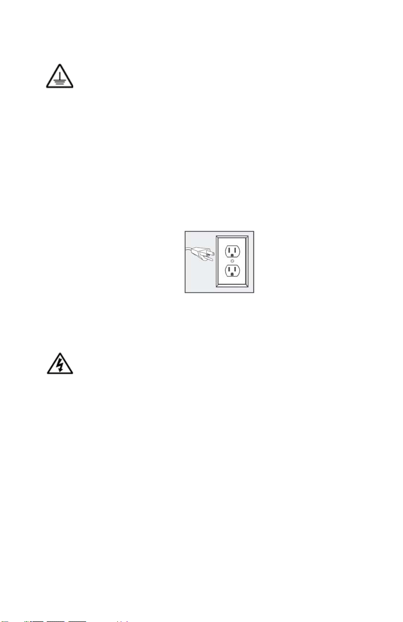
This appliance is for use on a nominal 120-volt circuit and has a grounding
attachment plug that looks like the plug illustrated. Make sure that the
appliance is connected to an outlet having the same configuration as the
plug.
Please Note* For UK, Australia, Asia etc. your voltage will be
220-240v. Check the label on the base of the turbine to ensure
your unit is at the correct voltage for your location.
ELECTRIC SHOCK HAZARD
Improper connection of the equipment grounding conductor can
result in the risk of electric shock.
· Check with a qualified electrician or service person if you are in doubt
as to whether the outlet is properly grounded.
· Use only a 3-wire extension cord that has a 3-blade grounding plug
and a 3-slot receptacle that accepts the plug on the product.
· An undersized cord results in a drop in line voltage and loss of power
and overheating.
· Do not modify the plug provided with the appliance. If it will not fit the
outlet, have a proper outlet installed by a qualified electrician.
· To reduce the risk of electric shock or injury, do not expose to rain.
· Never allow unit to freeze.
2 23

· Always store the unit inside in a dry location. Store on the floor if in a
basement setting.
· The operator must wear shoes and the floor must not be wet.
FIRE AND EXPLOSION HAZARD
Turbine must not be used in an area contaminated by volatile or
flammable materials since sparking can be expected in the
normal operation of the motor. This could ignite the contaminants causing a dangerous explosion.
· Do not spray flammable or combustible materials near an open flame
or sources of ignition such as cigarettes, motors, and electrical
equipment.
· Keep spray area well-ventilated. Keep a good supply of fresh air
moving through the area. Keep turbine in a well ventilated area.
· Do not spray turbine.
· Turn off and disconnect power cord before servicing equipment.
· Do not smoke in the spray area.
· Do not operate light switches, engines, or similar spark producing
products in the spray area.
· Keep area clean and free of paint or solvent containers, rags, and
other flammable materials.
· Fire extinguisher equipment shall be present and working.
· Sprayer generates sparks. When flammable liquid is used in or near
the sprayer or for flushing or cleaning, keep sprayer at least 20 feet
(6 m) away from explosive vapors or spraying area.
· Ensure ground prongs are intact on sprayer and extension cords.
· Always disconnect unit from main supply when filling the paint
container.
TOXIC FLUID OR FUMES HAZARD
Toxic fluids or fumes can cause serious injury or death if
splashed in the eyes or on skin, inhaled, or swallowed.
· Read MSDS (Material Safety Data Sheet) to know the specific
hazards of the fluids you are using.
· Always wear appropriate gloves and eye protection
· Always wear a respirator or mask. Read all instructions of the
respirator or mask to ensure that it will provide the necessary
protection against the inhalation of harmful vapors. Please also check
with the local jurisdiction.
3

· Paint, solvents, insecticides and other materials may be harmful if
inhaled.
· Store hazardous fl uid in approved containers, and dispose of it
according to applicable guideline.
· Do not stop or defl ect fl uid leaks with your hand or body.
EQUIPMENT MISUSE HAZARD
Misuse of equipment can cause serious injury or death.
· Never aim the spray gun at another person or animal. In the event of
injury, seek expert medical advice immediately.
· Do not operate or spray near children. Keep children away from
equipment at all times.
· Do not overreach or stand on an unstable support. Keep eff ective
footing and balance at all times.
· Stay alert and watch what you are doing.
· Do not operate the unit when fatigued or under the infl uence of drugs
or alcohol.
· Do not kink or over-bend the hose.
· Do not use the hose as a strength member to pull or lift the
equipment.
· Do not cover turbine case as this will restrict air to the intake and
result to overheating and premature failure of the motor.
· Do not carry turbine while spraying.
· Check the hose, hose connectors and power cord daily. Any worn or
damaged parts should be replaced immediately.
· Use only genuine Fuji Spray replacement parts.
· It is normal for the turbine air outlet (manifold) to become hot during
use, please allow your Fuji Spray turbine to cool for a few minutes
before removing the hose from the turbine manifold.
Prop 65 Warning for California Residents
WARNING: This product may contain chemicals known
to the State of California to cause cancer, birth defects, or
other reproductive harm.
4 21

GETTING STARTED
Please register your Fuji Spray Product at www.fujispray.com/product-registration
NOTE: Throughout this Manual we have used the generic word ‘Paint’ to
describe all and any coatings. Please substitute the word ‘Paint’ for
whatever finish or coating you are spraying.
Your Fuji Spray Gun has been adjusted at the factory and is ready for
spraying. To clean out any impurities that may have accumulated during
assembly or shipping, we recommend spraying a small quantity of clean
paint thinner through the gun. Before tackling any serious spraying,
experiment with the Gun on a scrap piece of wood until you become
familiar with all the controls.
HOSE CONNECTION
Connect the Hex Nut at the end of the Hose (Female Connector) to the
Turbine Air Outlet. Tighten this Nut lightly. Overturning could cause
the internal Manifold to rotate and break the internal Seal to the
Motor. A Male Quick Connect Coupler 2046M is available as an acces-
sory for the connection to the turbine.
AIR CONTROL VALVE
The Air Control Valve 2032 is located on the Hose next to the brass
Quick-Connect. It provides you with a means of controlling the air flow
through the Gun. It offers you fingertip control when you need it to
reduce bounceback and overspray. It is important to remember that the
Air Control Valve - is the ‘last in the chain’ of operations after...
1) Thinning the paint
2) Adjusting the shape and size of the spray pattern
3) Adjusting the flow of paint through the Gun.
After performing these operations, you should spray a few passes onto a
scrap piece of plywood or cardboard. This will allow you to determine if
the paint levels nicely. Once the Gun is producing a perfect finish with
full air, you may then experiment with turning the air down until
bounceback is reduced to a mininum. However, if orange-peel results,
you have no option but to turn the air up again a slight amount.
PLASTIC DIAPHRAGM
The 1 Quart pressurized Cup has a plastic Diaphragm 2038 (not found in
the Gravity Spray Gun). This Diaphragm prevents paint from entering the
Pressure Tube 2024. The small air hole in the Diaphragm should not be
placed directly below the air hole in the Nipple. Position the Diaphragm
hole to the rear of the Cup. The Spray Gun can be turned to different
angles when spraying but never turned more than horizontal.
5

CHANGING THE SHAPE OF THE FAN
A) Loosen the Collar 5201. Turn the Air Cap 5202 to the horizontal
position then re-tighten the Collar to lock it into place. This setting
produces a vertical spray pattern. This pattern is used more than any
other by experienced spray painters.
B) Setting the Air Cap in a vertical position produces a horizontal
spray pattern. To lock it in position, tighten the Collar. The horizontal
fan pattern is the most useful for painting vertically such as a
doorframe.
CHANGING THE SIZE OF THE FAN
To produce a smaller fan pattern, turn the Pattern Control Knob
5225 counter-clockwise. Because the spray pattern size is now much
smaller, you must turn down the amount of paint spraying through
the Nozzle at the Fluid Adjusting Knob 5221 (rear of gun). If you do
not do this, you will get runs.
To set the fluid output, simply turn the Fluid Adjusting Knob counterclockwise for more ‘paint’ and clockwise for less. Once you set the
fluid to your liking, you can leave it in this position - unless of course,
you change the size of the fan pattern.
For the very smallest pattern (less than 1”), you must move the Gun
closer to the workpiece - but don’t forget to reduce the amount of
paint at the Fluid Adjusting Knob.
6
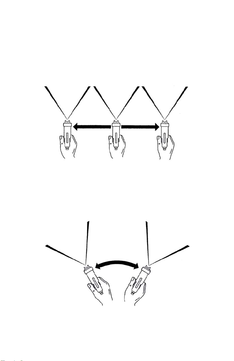
ACTUAL SPRAYING TECHNIQUES.
The Spray Gun should be held perpendicular to the surface at all
times. HOLD THE GUN NO MORE THAN 8” (20cm) AWAY FROM
THE SURFACE TO BE PAINTED.
CORRECT METHOD
Start off the piece. Pull the Trigger and move the Spray Gun in the
direction you want to spray. Continue off the edge of the piece on the
other end before releasing the Trigger. Between each successive pass,
overlap by about a half.
INCORRECT METHOD
CAUTION: Never, for any reason, point the Spray Gun directly at
the face, or head of a person.
7

AIR CAP SET SELECTION
Six additional size Setups are available as accessories. Size No.3
(1.3mm) is standard with all Fuji T-Spray Guns. 1.0mm, 1.3mm or
1.5mm can be used for any type of fine-finishing application. The
larger sizes such as 1.5mm allow for more fluid output - desirable with
fast drying lacquers.
AIR CAP SET - Part 5100 Series
If you do not intend on spraying walls & ceilings the only additional Setups you need would be the 1.0mm, 1.5mm, and
1.8mm.
No. 1 (Part 5100-1) .8mm (.031") SUPER-FINE OUTPUT
SHADING, STAINS.
No. 2 (Part 5100-2) 1.0mm (.039") FINE OUTPUT
SHADING, STAINS, WATERBORNE COATINGS.
No. 3 (Part 5100-3) 1.3mm (.051") FINE - MEDIUM OUTPUT -
STANDARD
WATER-BASED LACQUERS, ACRYLICS, POLYURETHANE,
STAINS.
No. 4 (Part 5100-4) 1.5mm (.059") MEDIUM OUTPUT
Similar to No. 3 but more coverage. Best for AUTOMOTIVE
ENAMELS, LACQUER and LATEX for cabinetry and furniture. Also
VARNISHES, PRIMERS, OIL-BASED PAINTS.
No. 5 (Part 5100-5) 1.8mm (.070") HIGH OUTPUT
Larger surfaces, thick layers, spotted effects. SEALERS, VARNISH,
POLYURETHANE, OIL BASED PAINTS, ENAMELS, EPOXIES,
LATEX on walls, ceilings ETC.
No. 6 (Part 5100-6) 2.0mm (.078") EXTRA HIGH OUTPUT
Very heavy flows, fast coverage. STONE FINISH PAINTS, TEXTURE
COATING, INDUSTRIAL PRIMERS, MULTI-FLECK PAINTS, LATEX on
walls, ceilings ETC.
No. 7 (Part 5100-7) 2.5mm (.098") MAXIMUM HIGH OUTPUT
Heavy flows, faster coverage. LATEX HOUSE PAINT on walls etc.
8 17
 Loading...