


Freescale Semiconductor
Data Sheet: Technical Data
MCF5253 ColdFire®
Document Number: MCF5253DS
Rev. 2, 03/2007
MCF5253
Package Information
MAPBGA–225
Microprocessor Data
Sheet
1 Introduction
This document provides an overview of the MCF5253
ColdFire processor and general descriptions of the
MCF5253 features and modules. Also provided are
electrical specifications, pin assignments, and package
diagrams for MCF5253 ColdFire® processor. For
functional characteristics, refer to the MCF5253
Reference Manual (MCF5253RM).
The MCF5253 is a general purpose system controller
with over 125 Dhrystone 2.1 MIPS @ 140 MHz
performance. The integrated peripherals and EMAC
allow the MCF5253 to replace both the microcontroller
and the DSP in certain applications. Most peripheral pins
can also be remapped as general purpose I/O pins.
Ordering Information: See Table 1 on page 2
1 Introduction . . . . . . . . . . . . . . . . . . . . . . . . . . . . 1
1.1 Orderable Part Numbers . . . . . . . . . . . . . . 2
1.2 Block Diagram . . . . . . . . . . . . . . . . . . . . . . 3
2 Functional Description . . . . . . . . . . . . . . . . . . . 4
2.1 Version 2 ColdFire Core . . . . . . . . . . . . . . . 4
2.2 Module Inventory . . . . . . . . . . . . . . . . . . . . 4
3 Signal Description . . . . . . . . . . . . . . . . . . . . . . 6
4 Electrical Specifications . . . . . . . . . . . . . . . . . 11
4.1 SDRAM Bus Timing . . . . . . . . . . . . . . . . . 14
4.2 SPDIF Timing . . . . . . . . . . . . . . . . . . . . . . 15
4.3 Serial Audio Interface Timing . . . . . . . . . . 16
4.4 DDATA/PST/PSTCLK Debug Interface . . 16
4.5 BDM and JTAG Timing . . . . . . . . . . . . . . 16
5 Package Information and Pinout . . . . . . . . . . 18
5.1 Pin Assignment . . . . . . . . . . . . . . . . . . . . 18
5.2 Package Drawing . . . . . . . . . . . . . . . . . . . 24
6 Product Documentation . . . . . . . . . . . . . . . . . 31
6.1 Revision History . . . . . . . . . . . . . . . . . . . . 31
Low power features include flexible PLL (with
power-down mode) with dynamic clock switching, a
hardwired CD ROM decoder, advanced 0.13 µm CMOS
process technology, 1.2 V core power supply, and
on-chip 128K-byte SRAM.
Freescale reserves the right to change the detail specifications as may be required to permit improvements in the design of its
products.
© Freescale Semiconductor, Inc., 2007. All rights reserved.
Introduction
For additional information regarding software drivers and applications, refer to
http://www.freescale.com/coldfire.
1.1 Orderable Part Numbers
Table 1 lists the orderable part numbers for the MCF5253 processor.
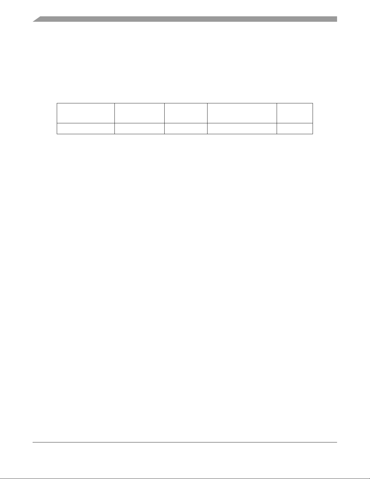
Table 1. Orderable Part Numbers
Orderable Part
Number
MCF5253VM140 140 MHz 225 MAPBGA -20 to +70°C Lead free
Maximum Clock
Frequency
Package Type
Operating Temperature
Range
Part Status
MCF5253 ColdFire Processor Data Sheet: Technical Data, Rev. 2
2 Freescale Semiconductor
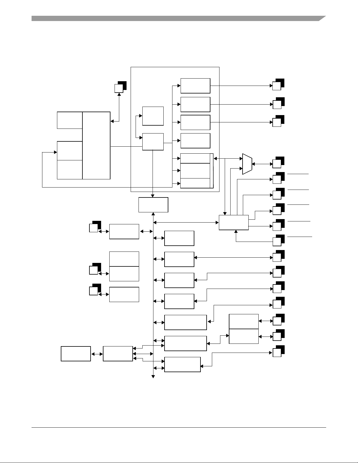
1.2 Block Diagram
Figure 1 illustrates the functional block diagram of the MCF5253 processor.
Introduction
Instruction
8K
Cache
64K
KRAM1
64K
KRAM0
“Backdoor” Interface
FlexCAN Pins
Debug
Module
with JTAG
ColdFire
CF2 Core
140 MHz
2x FlexCAN
Controller
Standard ColdFire Peripheral Blocks
Timer
I2C
5x08
DMA
5x08
Arbiter
Translator
UART (3)
5x08
Interrupt
E-bus
SDRAM
Interface
E-bus
Interrupt
Controller
MUX
SmartMedia
Timer Pins
I2C Pins
UART P ins
SDRAM
SRAM
IDE
BUFENB1
BUFENB
IDE
IDE_DIOW
IDE_IORDY
2
_DIOR
CRIN/CROUT Pins
RTC Pins
16 Kbyte
SRAM
Clock
PLL
XTAL
Oscillator
Real-Time
Clock
ARB
DMA
SPI
Interface
Audio
Interfaces
AD
Logic
Memory Stick/SD
Interface
USB 2.0
OTG Controller
ATA
Controller
USB
PHY
USB XTAL
Oscillator
Figure 1. MCF5253 Block Diagram
MCF5253 ColdFire Processor Data Sheet: Technical Data, Rev. 2
SPI Pins
Audio Interface
Pins
AD IN Pins
FlashMedia
Pins
USB Analog
USB XTAL Pins
ATA Pins
Freescale Semiconductor 3

Functional Description
2 Functional Description
2.1 Version 2 ColdFire Core
The V ersion 2 ColdFire (CF2) core consists of two independent, decoupled pipeline structures to maximize
performance while minimizing core size. The instruction fetch pipeline (IFP) is a two-stage pipeline for
prefetching instructions. The prefetched instruction stream is then gated into the two-stage operand
execution pipeline (OEP), which decodes the instruction, fetches the required operands, and then executes
the required function.
2.2 Module Inventory
Table 2 shows an alphabetical listing of the modules in the processor.
Table 2. Digital and Analog Modules
Block
Mnemonic
ATA Advanced Technology
ADC Battery Level/Keypad
AB Audio Bus Audio
AIM Audio Interface Audio
BROM Bootloader Boot ROM The MCF5253 incorporates a ROM Bootloader, which enables booting
FlexCAN Twin Controller Area
CSM Chip Select Module Connectivity
DMAC Direct Memory
Block Name
Attachment Controller
Analog/Digital
Converter
Network 2.0B
Communication Unit
Access Controller
Module
Functional
Grouping
Connectivity
Peripheral
Analog Input The six-channel ADC is based on the Sigma-Delta concept with 12-bit
Interface
Interface
Connectivity
Peripheral
Peripheral
Connectivity
Peripheral
The ATA block is an AT attachment host interface. Its main use is to
interface with IDE hard disc drives and ATAPI optical disc drives.
resolution. Both the analog comparator and digital sections are integrated
in the MCF5253.
The audio interfaces connect to an internal bus that carries all audio data.
Each receiver places its received data on the audio bus and each
transmitter takes data from the audio bus for transmission.
The audio interface module provides the necessary input and output
features to receive and transmit digital audio signals over serial audio
interfaces (IIS/EIAJ) and over digital audio interfaces (IEC958).
from UART, I2C, SPI, or IDE devices.
The FlexCan module is a full implementation of the Bosch CAN protocol
specification 2.0B, which supports both standard and extended message
frames.
Three programmable chip-select outputs (CS0
provide signals that enable glueless connection to external memory and
peripheral circuits.
There are four fully programmable DMA channels for quick data transfer.
Brief Description
/CS4, CS1, and CS2)
eMAC enhanced Multiply
Accumulate Module
MBUS Memory Bus Interface Bus Operation The bus interface controller transfers data between the ColdFire core or
MMC/SD Multimedia
Card/Secure Digital
Interface
MCF5253 ColdFire Processor Data Sheet: Technical Data, Rev. 2
4 Freescale Semiconductor
Core The integrated eMAC unit provides a common set of DSP operations and
enhances the integer multiply instructions in the ColdFire architecture.
DMA and memory, peripherals, or other devices on the external bus.
Flash Memory
Card Interface
The interface is Sony® Memory Stick®, SecureDigital, and Multi-Media
card compatible.
Note: The Sony Memory Interface does not support Sony MagicGate™.

Table 2. Digital and Analog Modules (continued)
Functional Description
Block
Mnemonic
Block Name
GPIO General Purpose I/O
Interface
GPT General Timer
Module
IDE Integrated Drive
Electronics
Functional
Grouping
System
integration
Timer
peripheral
Connectivity
peripheral
Brief Description
GPIO signals are multiplexed with various other signals.
The timer module includes two general-purpose timers, each of which
contains a free-running 16-bit timer.
The IDE hardware consists of bus buffers for address and data and are
intended to reduce the load on the bus and prevent SDRAM and Flash
accesses from propagating to the IDE bus.
INC Instruction Cache Core The instruction cache improves system performance by providing cached
instructions to the execution unit in a single clock cycle.
2
C Inter IC
I
Communication
Module
SRAM Internal 128-KB
SRAM
LIN Internal Voltage
Regulator
Connectivity
peripheral
Internal
memory
Linear
regulator
The two-wire I2C bus interfaces, compliant with the Philips I2C bus
standard, are bidirectional serial buses that exchange data between
devices.
The 128-Kbyte on-chip SRAM is split over two banks, SRAM0 (64K) and
SRAM1 (64K). It provides single clock-cycle access for the ColdFire core.
An internal 1.2 V regulator is used to supply the CPU and PLL sections of
the MCF5253, reducing the number of external components required and
allowing operation from a single supply rail, typically 3.3 volts.
JTAG Joint Test Action
Group
Test and
debug
To help with system diagnostics and manufacturing testing, the MCF5253
includes dedicated user-accessible test logic that complies with the IEEE
1149.1A standard for boundary scan testability, often referred to as Joint
Test Action Group, or JTAG.
QSPI Queued Serial
Peripheral Interface
Connectivity
Interface
RTC Real-Time Clock Timer
Peripheral
BDM Background Debug
Interface
SDRAMC Synchronous DRAM
Memory Controller
SIM System Integration
Module
PLL System Oscillator and
Phase Lock Loop
Test and
debug
Peripheral
Interface
System
Integration
System
Clocking
The QSPI module provides a serial peripheral interface with queued
transfer capability.
The RTC is a clock that keeps track of the current time even if the clock is
turned off.
A background-debug mode (BDM) interface provides system debug.
The SDRAM controller provides a glueless interface for one bank of
SDRAM, and can address up to 32MB. The controller supports a 16-bit
data bus. The controller operates in page mode, non-page mode, and
burst-page mode and supports SDRAMs.
The SIM provides overall control of the internal and external buses and
serves as the interface between the ColdFire core and the internal
peripherals or external devices. The SIM is responsible for the two
interrupt controllers (setting priorities and levels). And it also configures
the GPIO ports.
The oscillator operates from an external crystal connected across CRIN
and CROUT. The circuit can also operate from an external clock
connected to CRIN. The on-chip programmable PLL, which generates the
processor clock, allows the use of almost any low frequency external clock
(5–35 MHz).
MCF5253 ColdFire Processor Data Sheet: Technical Data, Rev. 2
Freescale Semiconductor 5

Signal Description
UART Universal
Asynchronous
Receiver
/Transmitter Module
USBOTG USB 2.0 High-Speed
On-The-Go
Connectivity
Peripheral
Connectivity
Peripheral
Three UARTs handle asynchronous serial communication.
The USB module is used for communication to a PC or communication to
slave devices; for example, to download data from a hard disc player to a
flash player, and to other devices.
3 Signal Description
This chapter describes the MCF5253 input and output signals. The signal descriptions as shown in Table 3
are grouped according to relevant functionality. For additional signal information, see “Chapter 2, Signal
Description” in the MCF5253 reference manual.
Table 3. MCF5253 Signal Index
Signal Name Mnemonic Function
Address A[24:1]
A[23]/GPO54
Read-write control RW Bus write enable—indicates if read
24 address lines—address 23 is
multiplexed with GPO54 and
address 24 is multiplexed with A20
(SDRAM access only).
or write cycle in progress.
Input/
Output
Out X
Out H
Reset
State
Output enable OE
Output enable for asynchronous
memorier TD-0.6(e5(e7(tc25)5.h(.)-4.8pus l6(es(.)]TJ18.1133 1.67 TD-0.0604 Tc0 Tw[(Out230m)4.n(l)-6.6ga(l)-6.te(l)-6.d(H)]TJ-47.3133 -3.67 TD-0.0025 Tc0.3005 TwData(l909)12.D[31:16]or)-23012.Data 4(b)2211()221 is uson)-5.7( )6.7(ttrmm)1)85non f3r l17158[(/[(Out261012.Hi-Zs )]TJ0267 TD-0.0019 Tc0.0039 TwSasynchrotp)-5.9s r do
addre sontbe1]
MCF5253 ColdFire Processor Data Sheet: Technical Data, Rev. 2
6 Freescale Semiconductor
Out230mlllH
SDMo

Signal Description
ISA bus read strobe IDE_DIOR/GPIO31
(CS2)
ISA bus write strobe IDE_DIOW/GPIO32
)
(CS2
1 ISA bus read strobe and 1 ISA bus
write strobe—allow connection of an
independent ISA bus peripheral,
such as an IDE slave device.
ISA bus wait signal IDE_IORDY/GPIO33 ISA bus wait line available for both
busses
Chip Selects[2:0] CS0/CS4
CS1/QSPICS3/GPIO28
Chip selects bits 2 through 0—
enable peripherals at programmed
addresses. C
S0 provides boot ROM
selection.
Buffer enable 1 BUFENB1/GPIO29 Two programmable buffer
In/Out –
In/Out –
In/Out –
Out
negated
In/Out
MCF5253 ColdFire Processor Data Sheet: Technical Data, Rev. 2
Freescale Semiconductor 7
Signal Description
Table 3. MCF5253 Signal Index (continued)
Signal Name Mnemonic Function
Serial data out SDATAO1/TOUT0/GPIO18
SDATAO2/GPIO34
Word clock LRCK1/GPIO19
Audio interfaces to serial data
outputs
Audio interfaces to serial word clocks In/Out –
Input/
Output
In/Out
Out
Reset
State
LRCK2/GPIO23
LRCK3/AUDIOCLOCK/GPIO43
Bit clock SCLK1/GPIO20
Audio interfaces to serial bit clocks In/Out –
SCLK2/GPIO22
SCLK3/GPIO35
Serial input EF/RXD2/GPIO6 Error flag serial in In/Out –
Serial input CFLG/GPIO5 C-flag serial in In/Out –
Subcode clock RCK/QSPIDIN/QSPIDOUT/
Audio interfaces to subcode clock In/Out –
GPIO26
Subcode sync QSPIDOUT/SFSY/GPIO27 Audio interfaces to subcode sync In/Out –
Subcode data QSPICLK/SUBR/GPIO25 Audio interfaces to subcode data In/Out –
Clock frequency trim XTRIM/TXD2/GPIO0 Clock trim control Out –
Audio clocks out MCLK1/GPIO11
DAC output clocks Out –
QSPICS2/MCLK2/GPIO24
Audio clock in LRCK3/AUDIOCLOCK/GPIO43 Optional audio clock input –
–
MemoryStick/
SecureDigital interface
EBUIN3/CMD_SDIO2/GPIO14 Secure Digital command lane—
In/Out –
MemoryStick interface 2 data I/O
EBUIN2/SCLKOUT/GPIO13 Clock out for both MemoryStick
In/Out –
interfaces and for Secure Digital
DDATA0/CTS1
/SDATA0_SDIO1/GPIO1 SecureDigital serial data bit 0—
In/Out –
MemoryStick interface 1 data I/O
SCL0/SDATA1_BS1/GPIO41 SecureDigital serial data bit 1—
In/Out –
MemoryStick interface 1 strobe
DDATA1/RTS1
/SDATA2_BS2/GPIO2 SecureDigital serial data bit 2—
In/Out –
MemoryStick interface 2 strobe
Reset output signal
SDA0/SDATA3/GPIO42 SecureDigital serial data bit 3 In/Out –
MCF5253 ColdFire Processor Data Sheet: Technical Data, Rev. 2
8 Freescale Semiconductor
Table 3. MCF5253 Signal Index (continued)
Signal Description
Signal Name Mnemonic Function
AT attachment interface
(IDE interface)
ATA_DIOW ATA write strobe signal Out –
ATA_DIOR ATA read strobe signal Out –
Input/
Output
Reset
State
ATA_IORDY ATA I/O ready input In –
ATA_DMARQ ATA DMA request In –
ATA_DMACK ATA DMA acknowledge Out –
ATA_INTRQ ATA interrupt request In –
ATA_CS0 ATA chip select 0 Out –
ATA_CS1 ATA chip select 1 Out –
ATA_A[2:0] 3-bit ATA address bus Out –
ATA_D[15:0] 16-bit ATA data bus In/Out –
CAN interface CAN0_TX CAN 0 transmit Out –
CAN0_RX CAN 0 receive In –
CAN1_TX CAN 1 transmit Out –
CAN1_RX CAN 1 receive In –
USB PHY interface USBVBUS USB Vbus input In –
USBID USB ID input In –
USBRES USB current programming resistor
Analog –
pin
USBDN USB DM signalling line In/Out –
USBDP USB DP signalling line In/Out –
USB oscillator USB_CRIN
USB_CROUT
RTC oscillator RTC_CRIN
RTCCROUT
AD IN ADIN0/GPI52
ADIN1/GPI53
Connections for USB oscillator
crystal (24 MHz)
Connections for real-time clock
crystal (32.768 kHz)
Analog-to-Digital Converter input
signals
In
Out
In
Out
In –
ADIN2/GPI54
ADIN3/GPI55
ADIN4/GPI56
ADIN5/GPI57
AD OUT ADREF
ADOUT/SCLK4/GPIO58
Analog-to-Digital Converter output
signal—connects to ADREF via
In/Out –
integrator network.
QSPI clock QSPICLK/SUBR/GPIO25 QSPI clock signal In/Out –
QSPI data in RCK/QSPIDIN/QSPIDOUT/GPIO26 QSPI data input In/Out –
–
–
MCF5253 ColdFire Processor Data Sheet: Technical Data, Rev. 2
Freescale Semiconductor 9
Signal Description
Table 3. MCF5253 Signal Index (continued)
Signal Name Mnemonic Function
QSPI data out RCK/QSPIDIN/QSPIDOUT/GPIO26
QSPI data out In/Out –
Input/
Output
Reset
State
QSPIDOUT/SFSY/GPIO27
QSPI chip selects QSPICS0/EBUIN4/GPIO15
QSPI chip selects In/Out –
QSPICS1/EBUOUT2/GPIO16
QSPICS2/MCLK2/GPIO24
CS1/QSPICS3/GPIO28
System oscillator in CRIN System input In –
System oscillator out CROUT System output Out –
Reset In RSTI Processor reset input In –
Freescale Test Mode TEST[2:0] TEST pins. In –
Linear regulator output LINOUT Output of 1.2 V to supply core Out –
Linear regulator input LININ Input, typically I/O supply (3.3V) In –
Linear regulator ground LINGND –
High Impedance HI_Z Assertion tri-states output signal pins In
Debug Data DDATA0/CTS1/SDATA0_SDIO1/GPIO1
DDATA1/RTS1
/SDATA2_BS2/GPIO2
Display of captured processor data
and break-point statuses
In/Out Hi-Z
DDATA2/CTS0/GPIO3
DDATA3/RTS0/GPIO4
Processor Status PST0/GPIO50
PST1/GPIO49
Indication of internal processor
status.
In/Out Hi-Z
PST2/INTMON2/GPIO48
PST3/INTMON1/GPIO47
Processor clock PSTCLK/GPIO51 Processor clock output Out –
Test Clock TCK Clock signal for IEEE 1149.1A JTAG In –
Test Reset/
Development Serial
Clock
DSCLK/TRST
Multiplexed signal that is
asynchronous reset for JTAG
controller. Also, clock input for debug
In –
module.
Test Mode Select/Break
Point
TMS/BKPT
Multiplexed signal that is test mode
select in JTAG mode and a hardware
In –
break-point in debug mode
Test Data Input/
Development Serial
TDI/DSI Multiplexed serial input for the JTAG
or background debug module.
In –
Input
Test Data
Output/Development
TDO/DSO Multiplexed serial output for the
JTAG or background debug module
Out –
Serial Output
MCF5253 ColdFire Processor Data Sheet: Technical Data, Rev. 2
10 Freescale Semiconductor

Electrical Specifications
4 Electrical Specifications
Table 4 through Table 9 provide the electrical characteristics for the MCF5253 processor. The remaining
figures and tables in this section provide the timing diagrams and the timing parameters for the MCF5253
processor.
Table 4 provides the maximum rating parameters for the MCF5253 processor.
Table 4. Maximum Ratings
Rating Symbol Value Units
Supply Core Voltage V
Maximum Core Operating Voltage V
Minimum Core Operating Voltage V
Supply I/O Voltage V
Maximum I/O Operating Voltage V
Minimum I/O Operating Voltage V
Input Voltage V
Storage Temperature Range T
cc
cc
cc
cc
cc
cc
in
stg
-0.5 to +2.5 V
+1.32 V
+1.08 V
-0.5 to +4.6 V
+3.6 V
+3.0 V
–0.5 to +6.0 V
–65 to +150
Table 5 provides the recommended operating temperatures for the MCF5253 processor.
Table 5. Operating Temperature
Characteristic Symbol Value Units
1
Maximum Operating Ambient Temperature T
Minimum Operating Ambient Temperature T
1
This published maximum operating ambient temperature should be used only as a system design guideline. All
device operating parameters are guaranteed only when the junction temperature does not exceed 86.5
Amax
Amin
+70
-20
o
C
o
C
o
C
o
C.
Table 6 provides the recommended operating supply voltages for the MCF5253 processor.
Table 6. Recommended Operating Supply Voltages
Pin Name Min Typ Max Unit
COREVDD 1.08 1.2 1.32 V
PADVDD 3.0 3.3 3.6 V
ADVDD 3.0 3.3 3.6 V
ADGND – GND – V
OSCPADVDD 3.0 3.3 3.6 V
OSCPADGND – GND – V
USBVDD – 3.3 – V
USBVDDP – 1.2 – V
MCF5253 ColdFire Processor Data Sheet: Technical Data, Rev. 2
Freescale Semiconductor 11

Electrical Specifications
Table 6. Recommended Operating Supply Voltages (continued)
Pin Name Min Typ Max Unit
USBGND – GND – V
RTCVDDA 3.0 – 4.2 V
RTCVSSA – GND – V
PLLCOREVDD 1.08 1.2 1.32 V
PLLCOREGND – GND – V
LININ 3.0 3.3 3.6 V
GND – GND – V
Table 7 provides the operating parameters for the linear regulator.
Table 7. Linear Regulator Operating Parameters
Characteristic Symbol Min Typ Max Units
Input Voltage (LININ) Vin 3.0 3.3 3.6 V
Output Voltage (LINOUT) Vout 1.08 1.2 1.32 V
Output Current Iout – 100 – mA
Power Dissipation Pd – – 500 mW
Load Regulation
10% Iout ≥ 90% Iout
Power Supply Rejection PSRR – 40 – dB
– – 50 60 mV
NOTE
A pmos regulator is used as a current source in this linear regulator, so a
10 µF capacitor (ESR 0... 5 Ohm) is needed on the output pin (LINOUT) to
integrate the current. Typically, this requires the use of a tantalum type
capacitor.
Table 8 provides the operating parameters for the ADC DC electrical characteristics.
Table 8. Operating Parameters for ADC DC Electrical Characteristics
Characteristic Symbol Min Typ Max Units
Operation Voltage Range for ADC ADVDD 3 – 3.6 V
Common Mode Rejection CMR 0 – ADVDD–1.1 v
Reference Voltage (external) ADREF 0 – ADVDD–1.1 v
Input offset voltage V
Input Hysteresis (ADINx = ADVDD/2) V
ADC Input Linear Operating Range ADINx 0 – ADVDD–1.1 V
offset
hyst
–10 – mV
0.73 0.78 0.85 mV
Table 9 provides the DC electrical specifications for the digital pins.
MCF5253 ColdFire Processor Data Sheet: Technical Data, Rev. 2
12 Freescale Semiconductor

Table 9. DC Electrical Specifications (I/O Vcc = 3.3 Vdc + 0.3 Vdc)
Characteristic Symbol Min Max Units
Electrical Specifications
Operation Voltage Range for I/O V
Input High Voltage V
Input Low Voltage V
Input Leakage Current @ 0.0 V/3.3 V
During Normal Operation
Hi-Impedance (Three-State) Leakage Current
@ 0.0 V/3.3 V During Normal Operation
Output High Voltage I
Output Low Voltage I
= 11.9 mA1, 6.3 mA2,3.1 mA
OH
= 7.1m A1, 3.5 mA2, 1.8 mA
OL
Schmitt Trigger Low to High Threshold Point
Schmitt Trigger High to Low Threshold Point
4
4
3
3
V
V
Load Capacitance:
D[31:16], SCLK[4:1], SCLKOUT, EBUOUT[2:1], LRCK[3:1], SDATAO[2:1], CFLG, EF,
_DIOR, IDE_DIOW, IDE_IORDY, MCLK1, MCLK2
IDE
Load Capacitance:
A[24:9], ATA_CS0, ATA_CS1, ATA_A[2:0], ATA_DIOR, ATA_DIOW, ATA_DMACK,
ATA_D[15:0], SDATAI[3,1]
Load Capacitance:
A[8:1], ADOUT, ATA_RST
BCLK, BCLKE, SDCAS, SDRAS, SDLDQM, SDCS0, SDUDQM, SDWE, BUFENB[2:1],
CAN0_TX, CAN1_TX, EBUIN1, RXD[2:0]
I
V
V
C
C
C
I
in
TSI
OH
OL
T+
cc
IH
IL
3.0 3.6 V
25.5 V
-0.3 0.8 V
– ±1 µA
– ±1 µA
2.4 – V
–0.4 V
1.67 1.79 V
1.01 1.15 V
T-
L
L
L
–50pF
15 40 pF
–30pF
Load Capacitance:
C
L
–20pF
SDA0, SDA1, SCL0, SCL1, CMD_SDIO2, SDATA2_BS2, SDATA1_BS1, SDATA0_SDIO1,
CS0/CS4, CS1, OE, RW, TA, TXD[2:0], XTRIM, TDO/DSO, RCK, SFSY, SUBR, SDATA3,
TOUT0, QSPID_OUT, QSPICS[3:0], QSPICLK, GPIO[6:5]
Load Capacitance:
C
L
–15pF
DDATA[3:0], PST[3:0], PSTCLK
Capacitance
1
8.0 mA: SCL0, SDA0, SCL1, SDA1, PST[3:0], DDATA[3:0], TDSO, RW, ATA_RST, MCLK1, QSPICS2_MCLK2
2
4.0 mA: BUFENB1, BUFENB2, EBUOUT1, SCLKOUT, CMDSDIO, IDE_DIOR, IDE_DIOW, TOUT0, RTS[1:0], TXD[1:0],
5
, Vin = 0 V, f = 1 MHz
C
IN
–6pF
SCLK[4:1], LRCK[4:1], SDATAO1, SDATAO2, QSPICLK, QSPICS0, QSPICS1_EBUOUT2, QSPICS3, QSPIDOUT, RCK,
XTRIM, A[8:1], ATA_CS0, ATA_CS1, ATA_A[2:0]
3
2.0 mA: TMS/BKPT, DSI/TDI, TRST/DSCLK
4
SCLK[4:1], SCL0, SCL1, SDA0, SDA1, ATA_DMARQ, ATA_INTRQ, ATA_IORDY
5
Capacitance CIN is periodically sampled rather than 100% tested.
MCF5253 ColdFire Processor Data Sheet: Technical Data, Rev. 2
Freescale Semiconductor 13

Electrical Specifications
Figure 2 and Table 10 provide the clock timing diagram and timing parameters.
CRIN
C5
PSTCLK
C6 C6
C7
BCLK
C8 C8
Figure 2. Clock Timing Definition
NOTE
Signals shown in Figure 2 are in relation to the SYSCLK clock. No
relationship between signals is implied or intended.
Table 10. Clock Timing Parameters
140 MHz CPU
ID Characteristic
Min Max
– CRIN Frequency with external oscillator 5.00 33.86 MHz
– CRIN Frequency with internal oscillator 5 16.94 MHz
C5 PSTCLK cycle time 7 – ns
C6 PSTCLK duty cycle 40 60 %
C7 BCLK cycle time 14.0 – ns
C8 BCLK duty cycle 35 65 %
Units
4.1 SDRAM Bus Timing
The SDRAM bus is a synchronous bus. Propagation delays, set-up times and hold times with respect to
the SDRAM clock BCLK are shown in Figure 3 and the parameters provided in Table 11. When BCLK
clock is not active, SDRAM interface is not valid and the external bus cannot be used.
MCF5253 ColdFire Processor Data Sheet: Technical Data, Rev. 2
14 Freescale Semiconductor

BCLK
D1
data (write)
D2
BCLKE, SDXDQM, SDWE
SDCS0
, SDRAS, SDCAS
,
D3
A[24:9]
data (read)
Figure 3. SDRAM Bus Timing Diagram
Electrical Specifications
D4
D5
Table 11. SDRAM Bus Timing Parameters
Timing to 50% Points
Maximum
ID Characteristic
30 pF
Load
D1 Propagation delay BCLK rising to data valid 7.88 8.8 9.6 ns
D2 Propagation delay BCLK rising to BCLKE, SDLDQM
SDUDQM, SDWE, SDCS0, SDRAS, SDCAS valid
D3 Propagation delay BCLK rising to A[24:9] valid 8.3 9.2 – ns
D4 Set-up time data valid to BCLK rising 0 0 0 ns
D5 Hold time BCLK rising to data valid 0.7 0.7 0.7 ns
,
40 pF
Load
8.7 – – ns
50 pF
Load
Units
4.2 SPDIF Timing
The Sony/Philips Digital Interface (SPDIF) timing parameters are provided in Table 12. SPDIF timing is
totally asynchronous, therefore there is no need for relationship with the clock. Table 12 shows the
differences between high-low and low-high propagation delay which is called the skew.
MCF5253 ColdFire Processor Data Sheet: Technical Data, Rev. 2
Freescale Semiconductor 15

Electrical Specifications
Table 12. SPDIF Propagation Skew and Transition Parameters
Characteristic Pin Load
EBUIN1, EBUIN2, EBUIN3, EBUIN4:
asynchronous inputs, no specs apply
EBUOUT1, EBUOUT2 output 40 pF – 1.5 24.2 31.3 ns
EBUOUT1, EBUOUT2 output 20 pF – 1.5 13.6 18.0 ns
1
Skew value does not include the skew introduced by different rise and fall times.
2
Transition times between 10% Vdd and 90% Vdd.
––0.7 – –ns
Prop Delay
Maximum
Maximum
Skew
1
Transit ion
2
Rise
Maximum
Transition Fall
Maximum
Units
4.3 Serial Audio Interface Timing
The Serial Audio Interface fully complies with the Industry standard Philips IIS (InterIC Serial Audio Bus)
timings.
4.4 DDATA/PST/PSTCLK Debug Interface
Table 13 provides the timing parameters.
Table 13. DDATA/PST/PSTCLK Debug Interface Timing Parameters
Characteristic Pin Load Min Max Units
PSTCLK clock rise edge to DDATA/PSTDATA1 invalid
PSTCLK clock rise edge to DDATA/PSTDATA
1
Note that output data may go invalid before rising edge of the clock. To clock data in reliably, you need to sample data, for
example, 2 ns before rising edge of clock.
2
Timing figure given takes 50% margin for noise and uncertainty on pin capacitance. Simulated clock-to-data, not taking noise
effects into account is 2.7 ns.
2
valid
15 pF –1.0 — ns
15 pF — 4.0 ns
4.5 BDM and JTAG Timing
Table 14 provides the BDM timing parameters.
Table 14. BDM Interface Timing Parameters
Characteristic Min Max Units
Clock period for DSCLK clock — 5T
Set-up time DSI, BKPT
Hold time DSI, BKPT to DSCLK rising edge — T+ 4.0 ns
Propagation delay DSCLK rising edge to TDO/DSO change 3T 4T + 32 ns
1
T denotes the CPU clock period. E.g. if the CPU is running at 100 MHz, T = 10 ns
, to DSCLK rising edge 4.0 — ns
1
Figure 4 provides the JTAG timing diagram and Table 15 provides the JTAG timing parameters.
ns
MCF5253 ColdFire Processor Data Sheet: Technical Data, Rev. 2
16 Freescale Semiconductor

Electrical Specifications
TCK
TDI, TMS
Boundary Scan
Data
Input
TRST
TDO
Boundary Scan
Data
Output
J2A
J1
J9
J11
J6
J4
J5
J7
J1
J10
J12
J2B
J3A
J3B
Figure 4. JTAG Timing Diagram
Table 15. JTAG Timing Parameters
ID Characteristic Min Max Units
– TCK Frequency of Operation 0 10 MHz
J1 TCK Cycle Time 100 — ns
J2A TCK Clock Pulse High Width 25 — ns
J2B TCK Clock Pulse Low Width 25 — ns
J3A TCK Fall Time (V
J3B TCK Rise Time (V
J4 TDI, TMS to TCK rising (Input Setup) 8 — ns
J5 TCK rising to TDI, TMS Invalid (Hold) 10 — ns
J6 Boundary Scan Data Valid to TCK (Setup) 1 — ns
J7 TCK to Boundary Scan Data Invalid to rising edge (Hold) 10 — ns
J8 TRST
Pulse Width (asynchronous to clock edges) 12 — ns
J9 TCK falling to TDO Valid (signal from driven or three-state) — 15 ns
J10 TCK falling to TDO High Impedance 2 15 ns
=2.4 V to VIL=0.5 V) — 5 ns
IH
=0.5 v to VIH=2.4 V) — 5 ns
IL
MCF5253 ColdFire Processor Data Sheet: Technical Data, Rev. 2
Freescale Semiconductor 17

Package Information and Pinout
Table 15. JTAG Timing Parameters (continued)
ID Characteristic Min Max Units
J11 TCK falling to Boundary Scan Data Valid (signal from driven or three-state) — 15 ns
J12 TCK falling to Boundary Scan. Data High Impedance 1 15 ns
5 Package Information and Pinout
This section includes the pin assignment information, contact connection diagram, and the mechanical
package drawing.
The MCF5253 device is available in the following package:
• 225 MAPBGA 13 x 13 mm 0.8 mm pitch package as shown in Figure 5.
5.1 Pin Assignment
Table 16 defines all the settings of each pad. See Figure 6 for the ball map of pin locations and Table 18
for the device pin list, sorted by signal identification.
Table 16. 225 MAPBGA Pin Assignment
Pinconfig
Register
Bit
GP
Reset Notes
Pin
Name
Drive Type/
Strength
Load
(pF)
1st
Function
2nd
Function
Address Bus
A1 O / 2 mA 30 –– ––X
A2 O / 2 mA 30 –– ––X
A3 O / 2 mA 30 –– ––X
A4 O / 2 mA 30 –– ––X
A5 O / 2 mA 30 –– ––X
A6 O / 2 mA 30 –– ––X
A7 O / 2 mA 30 –– ––X
A8 O / 2 mA 30 –– ––X
A9 O / 8 mA 30 –– ––X
A10 O / 8 mA 30 –– ––X
A11 O / 8 mA 30 –– ––X
A12 O / 8 mA 30 –– ––X
A13 O / 8 mA 30 –– ––X
A14 O / 8 mA 30 –– ––X
A15 O / 8 mA 30 –– ––X
A16 O / 8 mA 30 –– ––X
A17 O / 8 mA 30 –– ––X
A18 O / 8 mA 30 –– ––X
A19 O / 8 mA 30 –– ––X
A20/A24 O / 8 mA 30 A20 A24 31 – X
A21 O / 8 mA 30
A22 O / 8 mA 30 –– ––X
A23/GPO54 O / 8 mA 30 A23 ––O54 X
–– ––X
H
3
H
2
H
1
H
5
G
1
G
3
G
2
H
4
H
6
F
2
G
5
F
3
F
1
E
1
G
4
E
2
F
4
E
3
F
5
F
6
Audio Clock Select: 1-LRCK3
pin; 0-CRIN pin
D
3
D
1
D
2
Boot Mode Select:1-Memory
connected to CS0
–
–
–
–
–
–
–
–
–
–
–
–
–
–
–
–
–
–
–
–
–
; 0-Internal
boot rom
MCF5253 ColdFire Processor Data Sheet: Technical Data, Rev. 2
18 Freescale Semiconductor

Table 16. 225 MAPBGA Pin Assignment (continued)
Package Information and Pinout
Pinconfig
Register
Bit
GP
Reset Notes
Pin
Name
Drive Type/
Strength
Load
(pF)
1st
Function
2nd
Function
Data Bus
D16 IO / 8 mA 40 –– ––HI_Z
D17 IO / 8 mA 40 –– ––HI_Z
D18 IO / 8 mA 40 –– ––HI_Z
D19 IO / 8 mA 40 –– ––HI_Z
D20 IO / 8 mA 40 –– ––HI_Z
D21 IO / 8 mA 40 –– ––HI_Z
D22 IO / 8 mA 40 –– ––HI_Z
D23 IO / 8 mA 40 –– ––HI_Z
D24 IO / 8 mA 40 –– ––HI_Z
D25 IO / 8 mA 40 –– ––HI_Z
D26 IO / 8 mA 40 –– ––HI_Z
D27 IO / 8 mA 40 –– ––HI_Z
D28 IO / 8 mA 40 –– ––HI_Z
D29 IO / 8 mA 40 –– ––HI_Z
D30 IO / 8 mA 40 –– ––HI_Z
D31 IO / 8 mA 40 –– ––HI_Z
Bus Control
OE O / 4 mA 30 –– ––Negated
RW O / 4 mA 30 –– ––H
TA /GPIO12 IO / 2 mA 30 TA ––IO12 –
BUFENB1/GPIO29 IO / 2 mA 30 BUFENB1 ––IO29 –
BUFENB2/GPIO30 IO / 2 mA 30 BUFENB2 ––IO30 –
IDE_DIOR/GPIO31 IO / 2 mA 30 IDE_DIOR ––IO31 –
IDE_DIOW
IDE_IORDY
/GPIO32 IO / 2 mA 30 IDE_DIOW ––IO32 –
/GPIO33 IO / 2 mA 30 IDE_IORDY ––IO33 –
Chip Selects
CS0/CS4 O / 4 mA 30 CS0 CS4 ––Negated
CS1/QSPICS3/
IO / 2 mA 30 CS1 QSPICS3 25 IO28 Negated
GPIO28
SDRAM Controller
BCLK/GPIO40 IO / 8 mA 15 BCLK ––IO40 –
BCLKE/GPIO63 IO / 8 mA 20 BCLKE ––IO63 –
SDLDQM/GPO52 O / 8 mA 20 SDLDQM ––O52 –
SDUDQM/GPO53 O / 8 mA 20 SDUDQM ––O53 –
SDWE/GPIO38 IO / 8 mA 20 SDWE ––IO38 Negated
SDCS0/GPIO60 IO / 8 mA 20 SDCS0 ––IO60 Negated
SDRAS/GPIO59 IO / 8 mA 20 SDRAS ––IO59 Negated
SDCAS/GPIO39 IO / 8 mA 20 SDCAS ––IO39 Negated
ATA Interface
ATA_A0 O / 2 mA 40 –– –––
ATA_A1 O / 2 mA 40 –– –––
ATA_A2 O / 2 mA 40 –– –––
ATA_D0 IO / 8 mA 40 –– –––
ATA_D1 IO / 8 mA 40 –– –––
C
1
E
4
E
5
B
1
C
2
D
4
C
3
B
2
A
2
B
3
A
3
C
4
B
4
D
5
A
4
C
5
R
3
J
4
N
5
P
5
K
6
M
5
Controlled by CS2 registers
P
4
Controlled by CS2 registers
R
4
J
3
Boot Mode Select:1-CS0;
–
–
–
–
–
–
–
–
–
–
–
–
–
–
–
–
–
–
–
–
–
–
0-CS4
M
7
B
5
E
6
C
6
A
5
C
7
B
6
A
6
D
6
A
8
B
7
B
8
B
9
A
9
–
–
–
–
–
–
–
–
–
–
–
–
–
–
MCF5253 ColdFire Processor Data Sheet: Technical Data, Rev. 2
Freescale Semiconductor 19

Package Information and Pinout
Table 16. 225 MAPBGA Pin Assignment (continued)
Pinconfig
Register
Bit
GP
Reset Notes
Pin
Name
Drive Type/
Strength
Load
(pF)
1st
Function
2nd
Function
ATA_D2 IO / 8 mA 40 –– –––
ATA_D3 IO / 8 mA 40 –– –––
ATA_D4 IO / 8 mA 40 –– –––
ATA_D5 IO / 8 mA 40 –– –––
ATA_D6 IO / 8 mA 40 –– –––
ATA_D7 IO / 8 mA 40 –– –––
ATA_D8 IO / 8 mA 40 –– –––
ATA_D9 IO / 8 mA 40 –– –––
ATA _ D 10 IO / 8 m A 40 –– –––
ATA _ D 11 IO / 8 m A 40 –– –––
ATA _ D 12 IO / 8 m A 40 –– –––
ATA _ D 13 IO / 8 m A 40 –– –––
ATA _ D 14 IO / 8 m A 40 –– –––
ATA _ D 15 IO / 8 m A 40 –– –––
ATA_CS0 O / 2 mA 40 –– –––
ATA_CS1 O / 2 mA 40 –– –––
ATA_DIOR O / 8 mA 40 –– –––
ATA _ D IOW O / 8 m A 40 –– –––
ATA _I O R DY I –– – – ––
ATA _ IN T R Q I –– – – ––
ATA_DMARQ I –– – –––
ATA_DMACK O / 8 mA 40 –– –––
ATA _ RS T O / 2 mA 40 –– –––
Clock Generation
CRIN ––– – –––
CROUT
RTC_CRIN A
RTCCROUT A
USB_CRIN A
USB_CROUT A
XTRIM/TXD2/GPIO0 IO / 2 mA 30 XTRIM TXD2 0 IO0
––– – –––
–– – –––
–– – –––
–– – –––
–– – –––
–
JTAG/BDM/Test
TDO/DSO O / 4 mA 30 –– –––
TDI/DSI I
TMS/BKPT
I –– – – ––
TCK I
TRST/DSCLK I –– – –––
HI_Z
I –– – – ––
PSTCLK/GPIO51 IO / 8 mA 30 PSTCLK
PST0/GPIO50 IO / 4 mA 30 PST0 ––IO50 HI_Z
PST1/GPIO49 IO / 4 mA 30 PST1 ––IO49 HI_Z
PST2/INTMON2/
IO / 4 mA 30 PST2 INTMON2 17 IO48 HI_Z
GPIO48
PST3/INTMON1/
IO / 4 mA 30 PST3 INTMON1 18 IO47 HI_Z
GPIO47
–– – –––
–– – –––
––IO51 –
F
8
F
9
B
1
0
C
1
0
A
1
0
D
1
0
D
1
1
B
1
1
C
1
1
A
1
1
A
1
2
E
1
1
B
1
2
D
1
2
C
9
D
9
B
1
5
A
1
3
D
7
D
8
A
7
C
1
2
C
8
M
3
Main Processor Clock Input
N
2
Main Processor Clock Output
J
1
Real Time Clock (32.768 kHz)
Input
K
2
Real Time Clock (32.768 kHz)
–
–
–
–
–
–
–
–
–
–
–
–
–
–
–
–
–
–
–
–
–
–
–
Output
L
1
USB Clock (24 MHz) Input
4
L
1
USB Clock (24 MHz) Output
5
R
6
Interrupt Capable Input
G
1
See TEST0 Description
3
F
1
See TEST0 Description
5
F
1
See TEST0 Description
2
F
1
3
F
1
See TEST0 Description
4
B
1
For Normal Operation Tie This
3
Pin High
G
1
4
G
1
5
G
1
2
H
1
4
H
1
3
–
–
–
–
–
–
MCF5253 ColdFire Processor Data Sheet: Technical Data, Rev. 2
20 Freescale Semiconductor

Table 16. 225 MAPBGA Pin Assignment (continued)
Package Information and Pinout
Pinconfig
Register
Bit
GP
Pin
14,13 IO1 HI_Z
24,23 IO2 HI_Z
Name
DDATA0/CTS1/
SDATA0_SDIO1/GPIO1
DDATA1/RTS1
SDATA2_BS2/GPIO2
DDATA2/CTS0
DDATA3/RTS0
TEST0 I
TEST1 I
TEST2 I
/
/GPIO3 IO / 4 mA 30 DDATA2 CTS0 22 IO3 HI_Z
/GPIO4 IO / 4 mA 30 DDATA3 RTS0 21 IO4 HI_Z
Drive Type/
Strength
Load
(pF)
1st
Function
2nd
Function
IO / 4 mA 30 DDATA0 CTS1/SDATA
0_SDIO1
IO / 4 mA 30 DDATA1 RTS1/SDATA
2_BS2
–– – –––
–– – –––
–– – –––
Reset/Wake-up
RSTI I –– – –––
WAKEUP/GPIO21 IO / 2 mA 30 WAKEUP ––IO21 –
USB
USBDN A –– – –––
USBDP A –– – –––
USBID I –– – –––
USBVBUS A –– – –––
USBRES A –– – –––
TESTOUT
1
O –– – –––
NC ––– – –––
Audio Interface
SDATAI1/GPIO17 IO / 2 mA 30 SDATAI1 ––IO17 –
SDATAO1/TOUT0/
GPIO18
SCLK1/GPIO20 IO / 2 mA 30 SCLK1 ––IO20 –
LRCK1/GPIO19 IO / 2 mA 30 LRCK1 ––IO19 –
SDATAO2/GPIO34 IO / 2 mA 30 SDATAO2 ––IO34 –
SCLK2/GPIO22 IO / 2 mA 30 SCLK2 ––IO22 –
LRCK2/GPIO23 IO / 2 mA 30 LRCK2 ––IO23 –
SDATAI3/GPIO8 IO / 2 mA 30 SDATAI3 ––IO8 –
SCLK3/GPIO35 IO / 2 mA 30 SCLK3 ––IO35 –
LRCK3/AUDIOCLK/
GPIO43
EBUIN1/GPIO36 IO / 2 mA 30 EBUIN1
EBUIN2/SCLKOUT/
GPIO13
EBUIN3/
CMD_SDIO2/GPIO14
QSPICS0/EBUIN4/
GPIO15
EBUOUT1/GPIO37 IO / 2 mA 30 EBUOUT1 ––IO37 –
QSPICS1/
EBUOUT2/GPIO16
CFLG/GPIO5 IO / 2 mA 30 CFLG ––IO5 –
EF/RXD2/GPIO6 IO / 2 mA 30 EF RXD2
IO / 2 mA 30 SDATAO1 TOUT0 8 IO18 –
IO / 2 mA 30 LRCK3 AUDIOCLK – IO43 –
––IO36 –
IO / 2 mA 30 EBUIN2 SCLKOUT 16 IO13 –
IO / 2 mA 30 EBUIN3 CMDSDIO2 15 IO14 –
IO / 2 mA 30 QSPICS0 EBUIN4 30 IO15 –
IO / 2 mA 30 QSPICS1 EBUOUT2 29 IO16 –
– IO6 –
Reset Notes
K
1
Interrupt Capable Input
0
R
1
Interrupt Capable Input
1
J
1
Interrupt Capable Input
4
J
1
Interrupt Capable Input
2
F
1
BDM/JTAG Select: 1-BDM;
1
0-JTAG
G
1
For normal operation, tie this
0
pin low.
H
1
For normal operation, tie this
0
pin low.
E
1
5
R
5
N
1
5
M
1
5
M
1
1
N
1
4
M
1
4
P
1
3
R
1
4
N
9
R
8
K
8
P
8
D
1
5
E
1
3
E
1
4
N
1
0
R
1
0
M
1
See A20/A24 Description
0
N
6
M
6
K
7
R
7
P
6
N
8
M
9
Interrupt Capable Input
R
9
Interrupt Capable Input
–
–
–
–
–
–
–
–
–
–
–
–
–
–
–
–
–
–
–
–
–
–
–
–
MCF5253 ColdFire Processor Data Sheet: Technical Data, Rev. 2
Freescale Semiconductor 21

Package Information and Pinout
Table 16. 225 MAPBGA Pin Assignment (continued)
Pinconfig
Register
Bit
GP
Reset Notes
Pin
Name
Drive Type/
Strength
Load
(pF)
1st
Function
2nd
Function
MCLK1/GPIO11 IO / 4 mA 30 MCLK1 ––IO11 –
QSPICS2/MCLK2/
IO / 4 mA 30 QSPICS2 MCLK2 28 IO24 –
GPIO24
Analog-to-Digital Converter
ADIN0/GPI52 A – ADIN0 ––I52 –
ADIN1/GPI53 A – ADIN1 ––I53 –
ADIN2/GPI54 A – ADIN2 ––I54 –
ADIN3/GPI55 A – ADIN3 ––I55 –
ADIN4/GPI56 A – ADIN4 ––I56 –
ADIN5/GPI57 A – ADIN5 ––I57 –
ADREF A –– – –––
ADOUT/SCLK4/
IO / 2 mA 30 ADOUT SCLK4 9 IO58 –
GPIO58
FlexCAN
CAN0_TX O / 8 mA 30 –– –––
CAN0_RX I –– – – ––
CAN1_TX O / 8 mA 30 –– –––
CAN1_RX I –– – – ––
QSPI
QSPICLK/SUBR/
GPIO25
RCK/QSPIDIN/
QSPIDOUT/GPIO26
QSPIDOUT/SFSY/
GPIO27
IO / 2 mA 30 QSPICLK SUBR 27 IO25 –
IO / 2 mA 30 RCK QSPIDIN/
26 IO26 –
QSPIDOUT
IO / 2 mA 30 QSPIDOUT SFSY 10 IO27 –
I2C
SDA0/SDATA3/
GPIO42
SCL0/SDATA1_BS1/
GPIO41
SDA1/RXD1/GPIO44 IO / 4 mA 30 SDA1 RXD1 19 IO44 –
SCL1/TXD1/GPIO10 IO / 4 mA 30 SCL1 TXD1 20 IO10 –
IO / 4 mA 30 SDA0 SDATA3 11 IO42 –
IO / 4 mA 30 SCL0 SDATA1_BS1 12 IO41 –
UART
TXD0/GPIO45 IO / 2 mA 30 TXD0 ––IO45 –
RXD0/GPIO46 IO / 2 mA 30 RXD0 ––IO46 –
Power/Ground Pins
LININ ––– – –––
LINOUT
LINGND
PLLCOREVDD
(3 Balls)
PLLCOREGND
(3 Balls)
USBVDD (2 Balls)
USBVDDP
––– – –––
––– – –––
––– – –––
––– – –––
––– – –––
––– – –––
D
1
4
P
9
K
3
L
1
L
2
L
3
M
1
J
6
M
2
J
5
C
1
5
D
1
3
C
1
4
E
1
2
P
7
N
7
M
8
K
9
P
1
0
J
1
5
J
1
3
H
1
2
H
1
5
A
1
3.3 Volt Supply Required
4
B
1
1.2 Volt Output (Approx 50%
4
Efficient)
C
1
3
S
e
1.2 Volt Supply Required (M4,
e
N
ot
N3, P2)
e
s
S
e
N4,P3,R2
e
N
ot
e
s
S
e
3.3 Volt Supply Required (L13,
e
N
ot
M13)
e
s
L
1
1.2 Volt Supply Required
2
–
–
–
–
–
–
–
–
–
–
–
–
–
–
–
–
–
–
–
–
–
–
–
–
MCF5253 ColdFire Processor Data Sheet: Technical Data, Rev. 2
22 Freescale Semiconductor

Table 16. 225 MAPBGA Pin Assignment (continued)
Package Information and Pinout
Pinconfig
Register
Bit
GP
Reset Notes
Pin
Name
Drive Type/
Strength
Load
(pF)
1st
Function
2nd
Function
USBGND (3 Balls) ––– – –––
OSCPADVDD
OSCPADGND
––– – –––
––– – –––
RTC_VDDA ––– – –––
RTCVSSA
––– – –––
ADVDD ––– – –––
ADGND
––– – –––
PADVDD (10 Balls) ––– – –––
COREVDD
––– – –––
(4 Balls)
COREVSS/PADVSS
(18 Balls)
1
For test purposes only. Leave ball as open circuit.
2
These pads are listed as “GND” in the ball map and the rest of the tables.
2
––– – –––
S
e
K11, L11, M12
e
N
ot
e
s
N
1
3.3 Volt Supply Required
P
1
J
2
3.3 Volt Supply Required
K
1
K
4
3.3 Volt Supply Required
L
4
S
e
3.3 Volt Supply Required (E7,
e
N
ot
E9, F10, H8, H11, K5, L6, L8,
e
s
L10, R13)
S
e
1.2 Volt Supply Required (G8,
e
N
ot
H7, H9, J8)
e
s
S
e
A1, A15, E8, E10, F7, G6, G7,
e
N
ot
G9, G11, J7, J9, J10, J11, L5,
e
s
L7, L9, R1, R15
–
–
–
MCF5253 ColdFire Processor Data Sheet: Technical Data, Rev. 2
Freescale Semiconductor 23

Package Information and Pinout
5.2 Package Drawing
Figure 5 shows the package outline diagram for the MCF5253 processor.
TOP VIEW
Notes:
BOTTOM VIEW
1. All dimensions in millimeters.
2. Dimensioning and tolerancing per ASME Y14. 5M–1994.
3. Maximum solder ball diameter measured parallel to datum A.
4. Datum A, the seating plane, is determined by the spherical crown of the solder balls.
5. Parallelism measurement shall exclude any effect of mark on top surface of package.
SIDE VIEW
Figure 5. MCF5253 Package Drawing
MCF5253 ColdFire Processor Data Sheet: Technical Data, Rev. 2
24 Freescale Semiconductor

Freescale Semiconductor 25
5.2.1 MAPBGA Pinout
Figure 6 shows the MCF5253 ball map of pad locations.
123456789101112131415
GND D24 D26 D30
A
SDUDQM
GPO53
/
SDRAS/
GPIO59
ATA_DMAR
Q
ATA_A0 ATA_D1 ATA_D6 ATA_D11 ATA_D12 ATA_DIOW LININ
GND
A
D19 D23 D25 D28
B
MCF5253 ColdFire Processor Data Sheet: Technical Data, Rev. 2
D16 D20 D22 D27 D31
C
A22A23/GPO54A21 D21 D29
D
A14 A16 A18 D17 D18
E
A13 A10 A12 A17 A19 A20/A24 G ND ATA _ D 2 ATA _ D3 PADVDD TEST0 TMS/BKPT TCK
F
A5 A7 A6 A15 A11 GND GND COREVDD GND TEST1 GND
G
A3 A2 A1 A8 A4 A9 COREVDD PA DV D D COREVDD TEST2 PA DV D D
H
RTC_CRIN RTC_VDDA CS0/CS4 RW
J
RTCVSSA RTCCROUT
K
ADIN1/
L
GPI53
M
N
P
R
ADIN4/
GPI56
OSCPAD
VDD
OSCPAD
GND
GND
ADREF CRIN
CROUT
PLLCORE
PLLCORE
ADIN2/
GPI54
VDD
GND
ADIN0/
GPI52
ADIN3/
GPI55
PLLCORE
VDD
PLLCORE
GND
OE
ADVDD PAD V DD
ADGND
PLLCORE
VDD
PLLCORE
GND
IDE_DIOW/
GPIO32
IDE_IORDY/
GPIO33
BCLK/
GPIO40
ADOUT/
SCLK4/
GPIO58
GND PADV D D GND PA DV DD GND PA DV DD USBGND USBVDDP USBVDD USB_CRIN
IDE_DIOR
GPIO31
TA
/GPIO12
BUFENB1/
GPIO29
WAKEUP/
GPIO21
SDCS0
GPIO60
SDLDQM
GPO52
SDCAS
GPIO39
BCLKE/
GPIO63
ADIN5/
GPI57
BUFENB2
GPIO30
EBUIN2/
/
SCLKOUT/
GPIO13
EBUIN1/
GPIO36
EBUOUT1/
GPIO37
XTRIM/
TXD2/
GPIO0
/
ATA_A1 ATA_A2 ATA_D0 ATA_D4 ATA_D9 ATA_D14 HI_Z
/
SDWE/
GPIO38
/
ATA_IORDY ATA_INTRQ ATA_CS1 ATA_D7 ATA_D8 ATA_D15 CAN0_RX
PA DV D D GND PAD VD D GND ATA_D13 CAN1_RX
GND COREVDD GND GND GND
EBUIN3/CM
/
D_SDIO2/
GPIO14
CS1
QSPICS3/
GPIO28
RCK/QSPID
IN/QSPIDO
UT/GPIO26
QSPICLK/
SUBR/
GPIO25
QSPICS0/
EBUIN4/
GPIO15
ATA_RST ATA_CS0 ATA_D5 ATA_D10
DDATA0/
/SDAT
CTS1
A0_SDIO1/
GPIO1
LRCK3/
AUDCLK/
GPIO43
SDATAI3/
GPIO8
SCL0/SDAT
A1_BS1/
GPIO41
SCLK3/
GPIO35
/
SCLK1/
GPIO20
QSPIDOUT/
SFSY/
GPIO27
QSPICS1/
EBUOUT2/
GPIO16
LRCK1/
GPIO19
SDATAO1/
TOUT0/
GPIO18
SDA0/
SDATA3/
GPIO42
CFLG/
GPIO5
SDATAI1/
GPIO17
QSPICS2/
MCLK2/
GPIO24
EF/RXD2/
GPIO6
USBGND N/C N/C N/C N/C
USBID
DDATA1/RT
S1/SDATA2
_BS2/
GPIO2
ATA _D M AC
K
PST1/
GPIO49
TXD0/
GPIO45
DDATA3/
RTS0/
GPIO4
USBGND USBVDD USBRES USBDP
N/C N/C N/C USBVBUS USBDN
N/C N/C TESTOUT N/C N/C
N/C PADVDD NC
TDO/DSO
INTMON1/
SCL1/TXD1/
LINOUT ATA_DIOR
LINGND CAN1_TX CAN0_TX
SCLK2/
GPIO22
PST3/
GPIO47
GPIO10
MCLK1/
GPIO11
LRCK2/
GPIO23
TRST
DSCLK
PSTCLK/
GPIO51
PST2/
INTMON2/
GPIO48
DDATA2/
CTS0
GPIO3
/
SDA1/RXD1
/
USB_CROU
SDATAO2/
GPIO34
RSTI
TDI/DSI
PST0/
GPIO50
RXD0/
GPIO46
/GPIO44
T
GND
B
C
D
E
F
G
H
J
K
L
M
Package Information and Pinout
N
P
R
123456789101112131415
Figure 6. MCF5253 Ball Map

Package Information and Pinout
Table 17 shows the signal color and signal name legend.
Table 17. Signal Color/Name Legend
Color Name
None Signal name as listed
GND
PA DV D D
COREVDD
USBGND
Table 18 shows the device pin list, sorted by signal identification.
3
Table 18. MCF5253 13 x 13 BGA (225 Signal ID by Pad Grid Location)
Signal ID Pad Location
A1 H03
A10 F02
A11 G05
A12 F03
A13 F01
A14 E01
A15 G04
A16 E02
A17 F04
A18 E03
A19 F05
A2 H02
A20/A24 F06
A21 D03
A22 D01
A23/GPO54 D02
A3 H01
A4 H05
A5 G01
A6 G03
A7 G02
A8 H04
A9 H06
ADGND L04
ADIN0/GPI52 K03
ADIN1/GPI53 L01
ADIN2/GPI54 L02
ADIN3/GPI55 L03
ADIN4/GPI56 M01
ADIN5/GPI57 J06
ADOUT/SCLK4/GPIO58 J05
ADREF M02
ADVDD K04
MCF5253 ColdFire Processor Data Sheet: Technical Data, Rev. 2
26 Freescale Semiconductor

Package Information and Pinout
Table 18. MCF5253 13 x 13 BGA (225 Signal ID by Pad Grid Location) (continued)
Signal ID Pad Location
ATA_A0 A08
ATA_A1 B07
ATA_A2 B08
ATA _C S0 C 09
ATA _C S1 D 09
ATA_D0 B09
ATA_D1 A09
ATA _ D1 0 C1 1
ATA _ D1 1 A 11
ATA _ D1 2 A 12
ATA _ D1 3 E 11
ATA _ D1 4 B 12
ATA _ D1 5 D1 2
ATA _D 2 F0 8
ATA _D 3 F0 9
ATA_D4 B10
ATA_D5 C10
ATA_D6 A10
ATA_D7 D10
ATA_D8 D11
ATA_D9 B11
ATA_DIOR B15
ATA_DIOW A13
ATA _ DM A CK C 1 2
ATA_DMARQ A07
ATA _ IN T R Q D 08
ATA _I OR DY D 0 7
ATA _R ST
BCLK/GPIO40 B05
BCLKE/GPIO63 E06
BUFENB1
BUFENB2
/GPIO29 P05
/GPIO30 K06
CAN0_RX D13
CAN0_TX C15
CAN1_RX E12
CAN1_TX C14
CFLG/GPIO5 M09
COREVDD G08
COREVDD H07
COREVDD H09
COREVDD J08
CRIN M03
CROUT N02
/CS4 J03
CS0
/QSPICS3/GPIO28 M07
CS1
D16 C01
C08
MCF5253 ColdFire Processor Data Sheet: Technical Data, Rev. 2
Freescale Semiconductor 27

Package Information and Pinout
Table 18. MCF5253 13 x 13 BGA (225 Signal ID by Pad Grid Location) (continued)
Signal ID Pad Location
D17 E04
D18 E05
D19 B01
D20 C02
D21 D04
D22 C03
D23 B02
D24 A02
D25 B03
D26 A03
D27 C04
D28 B04
D29 D05
D30 A04
D31 C05
DDATA0/CTS1
DDATA1/RTS1
/SDATA0_SDIO1/GPIO1 K10
/SDATA2_BS2/GPIO2 R11
DDATA2/CTS0/GPIO3 J14
DDATA3/RTS0
/GPIO4 J12
EBUIN1/GPIO36 N06
EBUIN2/SCLKOUT/GPIO13 M06
EBUIN3/CMD_SDIO2/GPIO14 K07
EBUOUT1/GPIO37 P06
EF/RXD2/GPIO6 R09
GND A01
GND A15
GND E08
GND E10
GND F07
GND G06
GND G07
GND G09
GND G11
GND J07
GND J09
GND J10
GND J11
GND L05
GND L07
GND L09
GND R01
GND R15
HI_Z
_DIOR/GPIO31 M05
IDE
_DIOW/GPIO32 P04
IDE
_IORDY/GPIO33 R04
IDE
B13
MCF5253 ColdFire Processor Data Sheet: Technical Data, Rev. 2
28 Freescale Semiconductor

Package Information and Pinout
Table 18. MCF5253 13 x 13 BGA (225 Signal ID by Pad Grid Location) (continued)
Signal ID Pad Location
LINGND C13
LININ A14
LINOUT B14
LRCK1/GPIO19 P08
LRCK2/GPIO23 E14
LRCK3/AUDIOCLK/GPIO43 M10
MCLK1/GPIO11 D14
NC R14
OE
OSCPADGND P01
OSCPADVDD N01
PA DV D D E0 7
PA DV D D E0 9
PA DV D D F 10
PADVDD H08
PADVDD H11
PA DV D D K0 5
PA DV D D L 0 6
PA DV D D L 0 8
PA DV D D L 1 0
PADVDD R13
PLLAVDD M04
PLLCOREGND N04
PLLCOREGND P03
PLLCOREGND R02
PLLCOREVDD N03
PLLCOREVDD P02
PST0/GPIO50 G15
PST1/GPIO49 G12
PST2/INTMON2/GPIO48 H14
PST3/INTMON1/GPIO47 H13
PSTCLK/GPIO51 G14
QSPICLK/SUBR/GPIO25 P07
QSPICS0/EBUIN4/GPIO15 R07
QSPICS1/EBUOUT2/GPIO16 N08
QSPICS2/MCLK2/GPIO24 P09
QSPIDOUT/SFSY/GPIO27 M08
RCK/QSPIDIN/QSPIDOUT/GPIO26 N07
RSTI E15
RTC_CRIN J01
RTC_VDDA J02
RTCCROUT K02
RTCVSSA K01
RW J04
RXD0/GPIO46 H15
SCL0/SDATA1_BS1/GPIO41 P10
R03
MCF5253 ColdFire Processor Data Sheet: Technical Data, Rev. 2
Freescale Semiconductor 29

Package Information and Pinout
Table 18. MCF5253 13 x 13 BGA (225 Signal ID by Pad Grid Location) (continued)
Signal ID Pad Location
SCL1/TXD1/GPIO10 J13
SCLK1/GPIO20 K08
SCLK2/GPIO22 E13
SCLK3/GPIO35 R10
SDA0/SDATA3/GPIO42 K09
SDA1/RXD1/GPIO44 J15
SDATAI1/GPIO17 N09
SDATAI3/GPIO8 N10
SDATAO1/TOUT0/GPIO18 R08
SDATAO2/GPIO34 D15
SDCAS
/GPIO39 D06
SDCS0/GPIO60 B06
SDLDQM
SDRAS
/GPO52 C06
/GPIO59 A06
SDUDQM/GPO53 A05
/GPIO38 C07
SDWE
/GPIO12 N05
TA
TCK F13
TDI/DSI F15
TDO/DSO G13
TEST0 F11
TEST1 G10
TEST2 H10
TESTOUT P13
TMS/BKPT
/DSCLK F14
TRST
F12
TXD0/GPIO45 H12
USB_CRIN L14
USB_CROUT L15
USBDN N15
USBDP M15
USBGND K11
USBGND L11
USBGND M12
USBID M11
USBRES M14
USBVBUS N14
USBVDD L13
USBVDD M13
USBVDDP L12
WAKEUP
/GPIO21 R05
XTRIM/TXD2/GPIO0 R06
MCF5253 ColdFire Processor Data Sheet: Technical Data, Rev. 2
30 Freescale Semiconductor

Product Documentation
6 Product Documentation
This section includes the related product documentation and references to information posted on
Freescale’s external web page.
This document is labeled as the type: Data Sheet: Technical Data. Definitions for all Freescale document
types are available at: http://www.freescale.com.
You can also obtain information on the mechanical characteristics of the MCF5253 integrated
microprocessor at http://www.freescale.com/coldfire.
The following documents are required for a complete description of the device and are necessary for
proper design:
MCF5253 Reference Manual (order number: MCF5253RM)
MCF5253 Product Brief (order number: MCF5253PB)
6.1 Revision History
Table 19 summarizes revisions to this document.
Table 19. MCF5253DS Revision History
Rev. No. Substantive Change(s)
2 First public version.
MCF5253 ColdFire Processor Data Sheet: Technical Data, Rev. 2
Freescale Semiconductor 31

How to Reach Us:
Home Page:
www.freescale.com
E-mail:
support@freescale.com
USA/Europe or Locations Not Listed:
Freescale Semiconductor
Technical Information Center, CH370
1300 N. Alma School Road
Chandler, Arizona 85224
+1-800-521-6274 or +1-480-768-2130
support@freescale.com
Europe, Middle East, and Africa:
Freescale Halbleiter Deutschland GmbH
Technical Information Center
Schatzbogen 7
81829 Muenchen, Germany
+44 1296 380 456 (English)
+46 8 52200080 (English)
+49 89 92103 559 (German)
+33 1 69 35 48 48 (French)
support@freescale.com
Japan:
Freescale Semiconductor Japan Ltd.
Headquarters
ARCO Tower 15F
1-8-1, Shimo-Meguro, Meguro-ku,
Tokyo 153-0064, Japan
0120 191014 or +81 3 5437 9125
support.japan@freescale.com
Asia/Pacific:
Freescale Semiconductor Hong Kong Ltd.
Technical Information Center
2 Dai King Street
Tai Po Industrial Estate
Tai Po, N.T., Hong Kong
+800 2666 8080
support.asia@freescale.com
For Literature Requests Only:
Freescale Semiconductor Literature Distribution Center
P.O. Box 5405
Denver, Colorado 80217
1-800-521-6274 or 303-675-2140
Fax: 303-675-2150
LDCForFreescaleSemiconductor@hibbertgroup.com
Information in this document is provided solely to enable system and software implementers to use
Freescale Semiconductor products. There are no express or implied copyright licenses granted
hereunder to design or fabricate any integrated circuits or integrated circuits based on the information
in this document.
Freescale Semiconductor reserves the right to make changes without further notice to any products
herein. Freescale Semiconductor makes no warranty, representation or guarantee regarding the
suitability of its products for any particular purpose, nor does Freescale Semiconductor assume any
liability arising out of the application or use of any product or circuit, and specifically disclaims any
and all liability, including without limitation consequential or incidental damages. “Typical” parameters
that may be provided in Freescale Semiconductor data sheets and/or specifications can and do vary
in different applications and actual performance may vary over time. All operating parameters,
including “Typicals”, must be validated for each customer application by customer’s technical experts.
Freescale Semiconductor does not convey any license under its patent rights nor the rights of others.
Freescale Semiconductor products are not designed, intended, or authorized for use as components
in systems intended for surgical implant into the body, or other applications intended to support or
sustain life, or for any other application in which the failure of the Freescale Semiconductor product
could create a situation where personal injury or death may occur. Should Buyer purchase or use
Freescale Semiconductor products for any such unintended or unauthorized application, Buyer shall
indemnify and hold Freescale Semiconductor and its officers, employees, subsidiaries, affiliates, and
distributors harmless against all claims, costs, damages, and expenses, and reasonable attorney
fees arising out of, directly or indirectly, any claim of personal injury or death associated with such
unintended or unauthorized use, even if such claim alleges that Freescale Semiconductor was
negligent regarding the design or manufacture of the part.
Freescale™ and the Freescale logo are trademarks of Freescale Semiconductor, Inc. All other
product or service names are the property of their respective owners.
© Freescale Semiconductor, Inc. 2007. All rights reserved.
Document Number : MCF5253DS
Rev. 2
03/2007
 Loading...