

Page 1

TS-STS
TS-STS
Quick Start Guide
Quick Start Guide
Sump Test System
Sump Test System
Pg 1
TS-STS Overview
The TS-STS system includes a TS-STS console within a convenient
portable case, leak testing probes with 50 feet of cable, and probe
hanging hardware (slip rings and chain).
After all fittings within the sump are sealed, the sump is filled with a
water-based test solution that covers all sump penetration holes. The
probe is installed so the float is floating on the surface of the test solution.
The TS-STS console is quickly programmed with the site name and
address, number of sumps, the 7-digit code-names for each sump, and
the correct Time/Day/Date before leak testing.
Pressing the Test key at the console keypad starts sump leak tests for
all sumps. The test time is 15 minutes and tests for a level change
greater than 0.002 inches. If the level of a sump drops more than the
leak
limit during the test, the Sump Leak Test Report will show a fail
result when the test is finished. Leak tests can also be programmed
(scheduled) to start at desired times.
When finished, leak test reports will automatically print out at the console
printer. Extra copies of this report can be printed using the report key. A
newly completed Sump Leak Test will overwrite the previous results
stored in memory. Save sump leak test reports and provide copies as
evidence of compliance with regulations.
TS-STS Installation
1
1.) Required Materials:
a.) Tape to secure the probe cable b.) Safety cones & signs
c.) Grounded, 3-pronged extension cord
d.) Flat pieces of metal to suspend leak testing probe over sumps
2.) Work safely — install Safety Cones and Signs at the site
3.) The probes are precision instruments — handle with care!
4.) The STS probes are shipped with cables attached, do not remove
the cable from the probe end... remove at the console case only.
5.) Inspect probes for proper float movement before use, then install
probes as shown in Section 1
6.) Connect the yellow probe cables to the receptacles at the TS-STS
Make sure to line up keyways before inserting cable and
case.
tightening the screw-on connector.
7.) Locate the TS-STS case outside of the Hazardous Area and tape
the cable down to prevent probe movement during the test and to
reduce tripping hazards
Recommendation: Use a computer and the Tech version of
System Sentinel™ to record site data, sump code-names, and test
results. Test results can also be extracted from Comm Port 1 at
NOTE
INCON P/N 000-3004 Rev.D Feb. 2009 © www
This document may change without prior notice.
the bottom of the TS-STS console (also see Section 4).
Reference Federal and State regulations for leak limit and test
time requirements. Recommendations for locating the
I
console outside of the (Class
during testing, are based on NFPA 30, NFPA 30A and NFPA 70 (NEC).
, Division 1, Group D) Hazardous Areas
®
INCON
is a Registered Trademark of Franklin Fueling Systems
TS-STS
.fraklinfueling.com
8.) Setup / Program the TS-STS console per Section 2
9.) Start sump leak test(s) on sumps that are ready
10.) Always clean, dry, and store probes in the probe carrying case after
each use
11.) Test each of the probes on a monthly basis to ensure its ability to
detect leaks. Install the probe in a test container and initiate a test.
After 5 minutes, remove about 0.12 inches of water. When the test
completes, the test report should show a Failed result if the probe
is working properly.
Page 2
Pg 2
(
)
DISPENSER
DISPENSER
1 / 2
20 Feet - Min. Distance
Per NFPA 30A
TS-STS
SUMP TEST SYSTEM
TS-STS
SUMP TEST SYSTEM
3 / 4
SUMP
DISPENSER
4
3
2
1
GROUNDED
3 PRONG
EXTENSION
CORD REQ'D
5 / 6
DISPENSER
7 / 8
SAFETY
CONES
INCON RECOMMENDS
TESTING DISPENSOR
SUMPS IN GROUPS
SO OTHER DISPENSORS
ARE LEFT IN SERVICE
DURING TESTING
FLAT METAL
/ ANGLE IRON
REQUIRED
TO SUSPEND
PROBE
SIDE VIEW
SPLIT RING
TS-STS
SUMP TEST SYSTEM
TS-STS
SUMP TEST SYSTEM
SUMP
4
3
2
1
STS-PRB-12
LEAK TESTING
PROBE WITH:
TSP-SSP
STAINLESS
STEEL FLOAT
RECEPTACLES
FOR FOUR
SCREW-IN, PROBE
CABLE PLUGS
POWER CORD
WITH A GROUNDED
3-PRONGED
PLUG
BUILDING
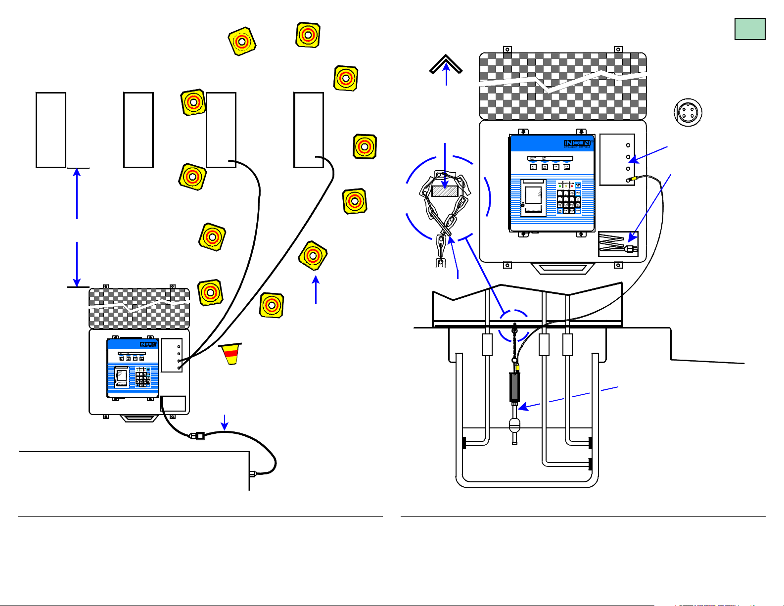
Figure 1.1 Typical Leak Detection Probe – Dispenser Sump Installation
Overview
DISPENSER SUMP
WITH TEST SOLUTION
(Side View)
Figure 1.2 Leak Detection Probe Installation
Dispenser Sump
Page 3
Pg 3
(
)
(
)
Tank Pad
10 Feet - Min. Distance
SAFETY
CONES
GROUNDED
3 PRONG
EXTENSION
CORD REQ'D
Turbine
Sump
1
Per NFPA 30A
TS-STS
SUMP TEST SYSTEM
TS-STS
SUMP TEST SYSTEM
Turbine
Sump
2
TAPE / WEIGHT DOWN
CABLE TO PREVENT
ACCIDENTAL
MOVEMENT DURING
LEAK TESTING
(PROBE CABLE
PN: 600-0200
= 50 FEET)
SUMP
4
3
2
1
Turbine
Sump
3
FLAT METAL
/ ANGLE IRON
REQUIRED
TO SUSPEND
PROBE
SIDE VIEW
SPLIT RING
TS-STS
SUMP TEST SYSTEM
TS-STS
SUMP TEST SYSTEM
STP
SUMP
4
3
2
1
STS-PRB-12
LEAK TESTING
PROBE WITH:
TSP-SSP
STAINLESS
STEEL FLOAT
RECEPTACLES
FOR FOUR
SCREW-IN, PROBE
CABLE PLUGS
POWER CORD
WITH A GROUNDED
3-PRONGED
PLUG
TURBINE SUMP
WITH TEST SOLUTION
Side View
BUILDING
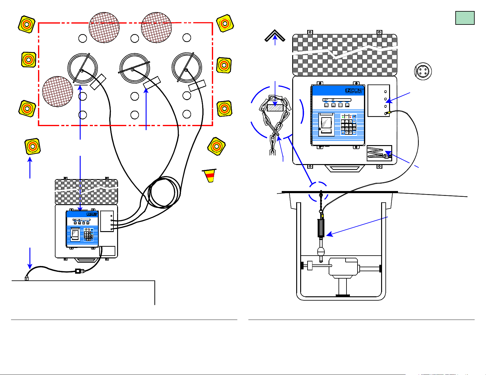
Figure 1.3 Typical Leak Detection Probe – Turbine Sump Installation
Overview
Figure 1.4 Leak Detection Probe Installation
Turbine Sump
—
❖
—
Page 4

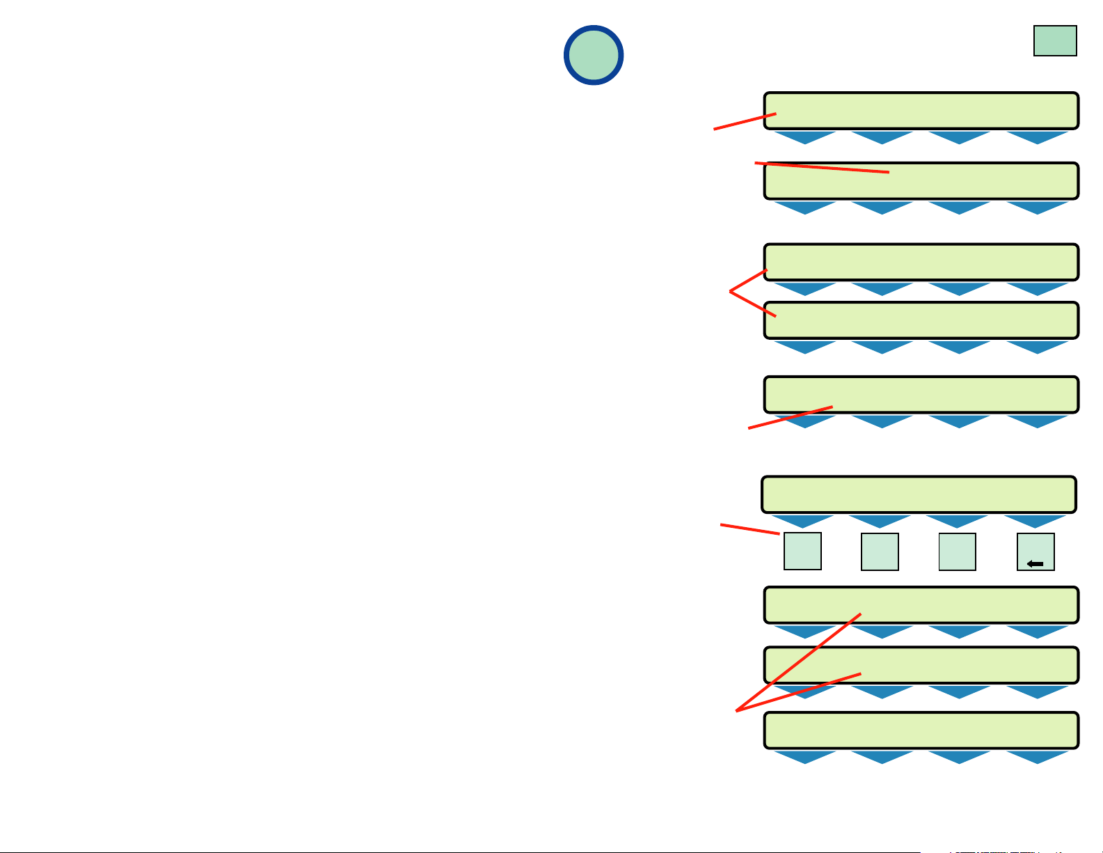
Setup - Program the Console
SELECT MENU OPTION
SETUP
SETUP MENU (MORE)
EXIT SYSTEM SUMPS CLK/CAL
SETUP MENU (MORE)
EXIT SYSTEM SUMPS CLK/CAL
SETUP MENU (MORE)
EXIT SYSTEM SUMPS CLK/CAL
SETUP MENU (MORE)
COM PORTS
Pg 4
2
NaNa
vigatingvigating
Na
vigating
NaNa
vigatingvigating
Menus:Menus:
Menus:
Menus:Menus:
• Push the
UP/DOWN
H U
MENU
7
keys ▲ ▼ to show
other menus or other
choices
• Use menu keys
M4)
to access menus
(M1
to
M1
LEFT
or to help edit text
• Press the
to make a setup choice
ENTER
key
M1
LEFT
or to move down in the
menu
• Press the
key to cancel before
entry or to move up
tree
CANCEL
M1
LEFT
and out of the menu
tree
M1
Input
Alphanumeric
LEFT
Press the Down key ▼ to see next display
Text
(in setup mode):
Press the
ACK
SHIFT
key at the keypad
1, or 2, or 3 times to
cycle between the
unique key characters
(at positions 1, 2, and 3).
Select and press a key
to input the desired
alphanumeric character.
M1
LEFT
ACK
SHIFT
Press the
the highlighted sequence below
to view the Setup Menus
M2
RIGHT
M2
RIGHT
M2
RIGHT
M2
RIGHT
M2
RIGHT
1 2
MENU
a b
key and follow
M3 M4
M3 M4
M3 M4
M3 M4
M3 M4
KEY
#
3
Display
Menu Select Keys
(M1 – M4)
Keypad:
(Multi-Function,
Alphanumeric)
ACK SHIFT key
Report Printer
(thermal printer)
Editing Text:
• Press the
• Use
• Use
M2
M4
NOTES
M1
key to move the cursor to the left
to move the cursor to the right
to backspace & delete text to the left of the cursor
Follow the highlighted sequence at left to program the
console.
Menus are in indented format (lower levels to the right).
The setup program factory default settings are shown
in ITALIC TEXT. The console will auto-exit the setup
mode if no key is pressed after 3 minutes.
Minimum Setup Requirements
1) From SETUP>SYSTEM (SYSTEM INFO), program the
System ID data and the No. (number of) Sumps
2) SETUP>SUMPS>DATA>SUMP N>NAME>Sump Name (code-
name for each containment sump that will be leak tested)
3) SETUP>CLK/CAL>Set Time (input the correct time), Set Date
(input the correct date), Set Day (choose the day of the week)
Page 5

Setup Menu
EXIT SYSTEM SUMPS CLK/CAL COM PORTS
Pg 5
Setup>System menu
SYSTEM INFO
SYSTEM ID (customize the Site ID information)
LINE 1
LOCATION LINE 1 (input 24 characters Max)
INCON Enter the Business Name
LINE 2
LOCATION LINE 2 (input 24 characters Max)
INTELLIGENT CONTROLS INC Enter other Business data
LINE 3
LOCATION LINE 3 (input 24 characters Max)
P.O. BOX 638 Enter the Street Address
LINE 4
LOCATION LINE 4 (input 24 characters Max)
SACO ME 04072 Enter the City and Zip code
LINE 5
LOCATION LINE 5 (input 24 characters Max)
1-800-984-6266 Enter the Business Number
NO. SUMPS (enter total number of sumps [4 max.])
NUMBER OF SUMPS
1
Setup>System menu Continued...
COLD BOOT (Replaces all custom-setup data with default values)
IF YOU CONTINUE, ALL SYSTEM PROGRAMMING
AND DATA WILL BE LOST...
:
PRESS ENTER IF YOU ARE SURE THAT
YOU WANT TO CONTINUE WITH COLD BOOT
Setup>Sumps menu
SUMPS
DATA
SUMP DATA
SUMP 1
SUMP
SUMP
2
:
4
SUMP DATA N
NAME (Rename the sump using a
SUMP NAME N Code-Name for each Sump)
SUMP N code-names can be up to 7
N = Sump number
Select sump and program new name
alphanumeric characters long
(e.g. ULD SMP, SUP SMP, DSP 1-2)
SUMP TST (sump leak test, start time + leak limit)
START TIME (Do not set when tests are started from the front panel)
SUMP TEST START TIME Tests are 15 minutes in length
00.28.00
LEAK LIM
LEAK LIMIT
0.002
Add 12 to pm times from 1 to 11:59 pm
(alarm threshold... 0.002 to 9999 in level units)
(12:28 am in 24 hour format)
Input time in 24 hour format...
Page 6
Setup>Clk/Cal menu
SYSTEM SUMP
OKAY OKAY
SYSTEM SUMP
WARNING OKAY
SYSTEM SUMP
NO PAPER OKAY
SYSTEM SUMP
OKAY OKAY
SYSTEM SUMP
OKAY TEST
LEVEL SUMP 1 SUMP 2 SUMP 3 SUMP 4
INCHES 2.01 3.09 1.76 3.12
SELECTFUNCTION 10:39:08 AM 10-29-2001
DISPLAY PRINTER
SYSTEM SUMP
OKAY LEAK
SELECT LEAK TEST OPTION
STATUS START ABORT
Leak Testing /
Pg 6
CLOCK/CALENDAR
DAY SAV
DAYLITE SAVINGS
ENABLED Enable
DISABLED Disable = does not
TM STYLE Select the time style for displays & reports
TIME STYLE
12 HOUR
24 HOUR
DT STYLE Select the time style for displays & reports
DATE STYLE
MM/DD/YY
DD/MM/YY
YY/MM/DD (YY = Year, MM = Month, DD = Day)
SET TIME Input current time in 24 hour format
SET SYSTEM TIME Two digits are required, use leading
HH:MM:SS
SET DATE Input current DATE
SET SYSTEM DATE
YYYY:MM:DD
SET DAY
SET SYSTEM DAY OF WEEK Select the current day
SUNDAY
MONDAY
TUESDAY
WEDNESDAY
THURSDAY
FRIDAY
SATURDAY
= allows daylight savings time changes
zeros before single digits
(e.g. input 05 not 5)
(YYYY = year, MM = Month, DD = Day)...
2 digits are required for month and day –
use leading zeros before single digits
(e.g.. input 04 not 4)
Add 12 to p.m. times
from 1 to 11:59 p.m.
3
Console Operation
Displays:
1.) Normal Display
2.) Press the Check key
to check the time and
date.
3.) The System –
Warning message
alternates with the
No Paper (if out).
Replace printer
paper before starting
sump leak tests.
4.) Press the Level key
to check the test fluid
level in sumps (sumps
can’t be leak tested if
empty).
5.) Press the Test key at
the keypad & and the
menu select key
(M1 M2
follow instructions to:
• Show the Status of
tests including Start
time / date
• Start tests, and to
• Abort leak test(s)...
Okay & Testing are
alternately displayed
when a sump leak
test is running.
or
M3)
and
M1
LEFT
M2
RIGHT
M3 M4
— ❖ —
Page 7

Leak Testing /
SELECT SUMP REPORT
TEST LEVEL
SELECT SUMP
SUMP 1 SUMP 2 SUMP 3 ALL
SELECT ALARM TYPE
SYSTEM SUMP ALL
SELECT (SYSTEM / SUMP) ALARM STATUS
ACTIVE CLEARED HISTORY
SELECT REPORT
SUMP ALARM
Console Operation Continued...
Pg 7
6.) To view an alarm/warning, press the M1 or M2 Key under the
word Alarm / Warning. While viewing the alarm, press the
SHIFT key at the keypad to acknowledge.
Cleared and
ACK
transient alarms should be acknowledged prior to starting
another test.
7.) Press the Report key at the keypad to show various report
choices.
—
❖
—
Reports
4
Reports can printout automatically or on
demand from the keypad. The
Sump Leak Test and Alarm
Reports print automatically.
The other reports, such as
the Sump Level Reports,
Alarm Reports, and Sump
Test Reports can be printed
on demand.
M1
LEFT
M2
RIGHT
M1
LEFT
M3 M4
ACK
SHIFT
J W
REPORT
M2
RIGHT
9
INCON
P .O. BOX 638
SACO ME 04072
1-800-984-6266
SUMP 1
M3
M1
LEFT
M4
M2
RIGHT
M3 M4
INTELLIGENT CONTROLS INC.
2.
10/31/2001 12:15 PM
SUMP LEAK TEST REPORT
TEST STARTED 12:00 PM
TEST STARTED 10/31/01
BEGIN LEVEL 2.0120 IN
END TIME 12:15 PM
END DATE 10/31/01
END LEVEL 2.0120 IN
LEAK THRESHOLD 0.002 IN
TEST RESULT : P ASSED
Press the menu select keys
and choose the type of report
that you wish to printout.
Alarm reports will print as
soon as an alarm is detected.
M1
LEFT
Leak test reports print
automatically after the leak test is finished.
Note that
when a new leak test is complete the data will
overwrite a previous result.
Of the three reports shown here, one is a Level
Summary report and two are Sump Leak Test
Reports.
Up to 4 sumps can be leak-tested at the same
time.
REPORTS continued...
M2
RIGHT
M3 M4
M1
LEFT
M2
RIGHT
M3 M4
INTELLIGENT CONTROLS INC.
10/31/2001 11:58AM
1.
SUMP 1
SUMP 2 7.201 IN
SUMP 3 3.218 IN
INCON
P.O.. BOX 638
SACO ME 04072
1-800-984-6266
SUMP LEVEL REPORT
2.012 IN
INTELLIGENT CONTROLS INC.
3.
10/31/2001 12:15 PM
SUMP LEAK TEST REPORT
TEST ST ARTED 12:00 PM
TEST ST ARTED 10/31/01
BEGIN LEVEL 7.0230 IN
END TIME 12:15 PM
END DATE 10/31/01
END LEVEL 7.0209 IN
LEAK THRESHOLD 0.002 IN
TEST RESULT : FAILED
INCON
P .O . BO X 638
SACO ME 04072
1-800-984-6266
SUMP 2
Page 8

Reports
Continued...
4
A digital copy of the Sump Test Report can be retrieved from the TS-STS
console through the communications port (Comm Port 1). This port is
located at the bottom side.
As with the printed reports, this data is overwritten when a new test is
run, so it must be collected after each test. The data can be stored in a
database as opposed to saving the printouts.
For more information on this feature contact INCON Technical Service at
1-800-984-6266.
Pg 8
—
INCON P/N 000-3004 Rev.D Feb. 2009 © Franklin Fueling Systems
This document may change without prior notice.
—
®
INCON
is a Registered Trademark of Franklin Fueling Systems
www
.franklinfueling.com
 Loading...